
INTERNATIONAL JOURNAL OF RESEARCH IN …ijrtm.com/iotg/sites/default/files/IJRTM242016-33.pdf ·...
7
INTERNATIONAL JOURNAL OF RESEARCH IN TECHNOLOGY AND MANAGEMENT (IJRTM) ISSN 2454-6240 www.ijrtm.com 55 Volume 2 Issue 4, JUNE 2016 AN ANALYSIS OF HEAT TRANSFER AND FRICTION: UNDER FORCED CONVECTION Amit Moray 1 , Preeti Singh 2 , 1 Assistant Professor, WIT, INDIA ABSTRACT The present work deals with the numerical investigation of heat transfer and friction from a rib roughened fin subjected to forced convection. Numerical data pertaining to heat transfer and friction from a rib roughened fin are generated by carrying out numerical simulations under the varied fluid flow conditions. Using a validated numerical model, the data pertaining to fluid flow and temperature distribution for different rib pitch to rib height ratio (P/e) are obtained by varying the Reynolds Number from 500 to 5000. The thermal and hydraulic performances of rib roughened fin are discussed with the help of Nusselt Number and friction factor plots. The results obtained from the rib roughened fin geometry are compared with that of a plain fin to determine the effectiveness of test fin in extracting heat from its base under similar operating conditions. The rib roughened fin having P/e of 6 whichbring out maximum enhancement in the heat transfer and friction. Keywords: Rib Roughened fin; Nusselt number; Friction factor; Reynolds number. I. INTRODUCTION Fins are used in a variety of engineering applications to enhance the convective heat transfer rate by achieving a large total heat transfer surface area without the use of an excessive amount of primary surface area. A fin is made of thermally conductive materials that extracts heat from its base and pass it on to the surrounding fluid through the large surface area. The design of cooling fins is encountered in many situations where the rate of heat transfer from a heat exchange surface plays a vital role in finalizing the shape, size and material for the systems. Several researches have been carried out to explore the effect of the system and flow parameters on the thermal performance of the engineering systems. The experimental and numerical approaches were adopted to study the heat transfer and friction characteristics of fin arrays so that the optimal geometric parameters can be selected under a specified operating conditions. Due to simple shape and ease in manufacturing, rectangular plate fins and pin fins are preferred in the majority of heat transfer applications. J. C. Han et al. [1] performed experiments on the rib-roughened surface to determine the effects of rib shape, angle of attack and pitch to rib height ratio on friction factor and heat-transfer results. They developed a general correlation for friction factor and heat transfer as function of rib shape, spacing and angle of attack and also reported that ribs at a 45 o angle of attack have superior heat transfer performance at a given pumping power. Rongguang Jia et al. [2] carried out a numerical investigation to determine the velocity and heat transfer characteristics of multiple impinging slot jets in rib-roughened channels. He considered different size and arrangement of jets and ribs and reported that the ribs enhance the heat transfer, if they are well arranged. Both the position and size of the ribs are of importance for heat transfer in rib-roughened channel. Larger recirculation zones induced by the jets near the roughened wall result in higher heat transfer coefficients. G. Iaccarinoet al. [3]investigated the effect of thermal boundary conditions on numerical heat transfer predictions in rib-roughened passages. They obtained results using constant heat flux. Their experimental measurements and data correlations showed that the predicted heat transfer is very sensitive to the type of boundary conditions used in the numerical model. It was illustrated that some of the discrepancies observed between experimental and numerical data can be eliminated if conduction heat transfer in the rib is taken into account. In the experimental study, P. M. Ligrani et al. [4] presented the spatially resolved Nusselt number, spatially averaged Nusselt number, and friction factor for a stationary channel roughened with the angled rib tabulators inclined at 45 o .Their results showed that the spatially resolved local Nusselt number reached to the maximum value at the top face of the rib tabulators, while the regions of flow separation and shear layer reattachment have pronounced influence on local surface heat transfer behavior .Xiufang Gao et al. [5] has shown that the flow behavior in rib-roughened duct is influenced by the inclination of ribs. Their study showed that the rib orientations not only affect the secondary flow style and its strength, but also alter the mean flow velocity distribution along the span wise direction and the secondary flow were found to be strongest for the one created by the ribs at 45 o .M.K. Gupta and S.C. Kaushik. [6] Conducted a comparative study of various types of artificial roughness geometries applied on the absorber plate of solar air heater duct to explore the heat transfer and friction characteristics and found that for the higher range of Reynolds number circular ribs and V shaped ribs give appreciable improvement in the energy efficiency for the higher values of Reynolds number; chamfered rib–groove geometry gives higher energy efficiency for relatively low values of Reynolds number. Bilen et al. [7] studied the effect of the geometric position of wall-mounted rectangular blocks on the heat transfer from the surface by carrying out experimental work. They reported that the most important parameter affecting the heat transfer is Reynolds number. It has been observed that heat transfer can be successfully improved by increasing the Reynolds number and the second most effective parameter for increasing the heat transfer is the turning angle of the blocks Apurba Layek [8] worked for optimization of roughness parameters of solar air heater based on effective efficiency criterion. He reported that solar air heater having absorber plate having chamfered rib – groove roughness shows higher thermal gain compared to smooth collectors with nearly same
-
Upload
hoanghuong -
Category
Documents
-
view
213 -
download
0
Transcript of INTERNATIONAL JOURNAL OF RESEARCH IN …ijrtm.com/iotg/sites/default/files/IJRTM242016-33.pdf ·...

INTERNATIONAL JOURNAL OF RESEARCH IN TECHNOLOGY AND MANAGEMENT (IJRTM) ISSN 2454-6240 www.ijrtm.com
55 Volume 2 Issue 4, JUNE 2016
AN ANALYSIS OF HEAT TRANSFER AND FRICTION: UNDER
FORCED CONVECTION Amit Moray
1, Preeti Singh
2,
1Assistant Professor, WIT, INDIA
ABSTRACT The present work deals with the numerical investigation
of heat transfer and friction from a rib roughened fin
subjected to forced convection. Numerical data pertaining
to heat transfer and friction from a rib roughened fin are
generated by carrying out numerical simulations under
the varied fluid flow conditions. Using a validated
numerical model, the data pertaining to fluid flow and
temperature distribution for different rib pitch to rib
height ratio (P/e) are obtained by varying the Reynolds
Number from 500 to 5000. The thermal and hydraulic
performances of rib roughened fin are discussed with the
help of Nusselt Number and friction factor plots. The
results obtained from the rib roughened fin geometry are
compared with that of a plain fin to determine the
effectiveness of test fin in extracting heat from its base
under similar operating conditions. The rib roughened fin
having P/e of 6 whichbring out maximum enhancement in
the heat transfer and friction.
Keywords: Rib Roughened fin; Nusselt number; Friction
factor; Reynolds number.
I. INTRODUCTION Fins are used in a variety of engineering applications
to enhance the convective heat transfer rate by achieving a
large total heat transfer surface area without the use of an
excessive amount of primary surface area. A fin is made of
thermally conductive materials that extracts heat from its base
and pass it on to the surrounding fluid through the large
surface area. The design of cooling fins is encountered in
many situations where the rate of heat transfer from a heat
exchange surface plays a vital role in finalizing the shape,
size and material for the systems. Several researches have
been carried out to explore the effect of the system and flow
parameters on the thermal performance of the engineering
systems. The experimental and numerical approaches were
adopted to study the heat transfer and friction characteristics
of fin arrays so that the optimal geometric parameters can be
selected under a specified operating conditions. Due to simple
shape and ease in manufacturing, rectangular plate fins and
pin fins are preferred in the majority of heat transfer
applications. J. C. Han et al. [1] performed experiments on
the rib-roughened surface to determine the effects of rib
shape, angle of attack and pitch to rib height ratio on friction
factor and heat-transfer results. They developed a general
correlation for friction factor and heat transfer as function of
rib shape, spacing and angle of attack and also reported that
ribs at a 45o angle of attack have superior heat transfer
performance at a given pumping power. Rongguang Jia et
al. [2] carried out a numerical investigation to determine the
velocity and heat transfer characteristics of multiple
impinging slot jets in rib-roughened channels. He considered
different size and arrangement of jets and ribs and reported
that the ribs enhance the heat transfer, if they are well
arranged. Both the position and size of the ribs are of
importance for heat transfer in rib-roughened channel. Larger
recirculation zones induced by the jets near the roughened
wall result in higher heat transfer coefficients.G. Iaccarinoet
al. [3]investigated the effect of thermal boundary conditions
on numerical heat transfer predictions in rib-roughened
passages. They obtained results using constant heat flux.
Their experimental measurements and data correlations
showed that the predicted heat transfer is very sensitive to the
type of boundary conditions used in the numerical model. It
was illustrated that some of the discrepancies observed
between experimental and numerical data can be eliminated if
conduction heat transfer in the rib is taken into account. In the
experimental study, P. M. Ligrani et al. [4] presented the
spatially resolved Nusselt number, spatially averaged Nusselt
number, and friction factor for a stationary channel
roughened with the angled rib tabulators inclined at 45o.Their
results showed that the spatially resolved local Nusselt
number reached to the maximum value at the top face of the
rib tabulators, while the regions of flow separation and shear
layer reattachment have pronounced influence on local
surface heat transfer behavior .Xiufang Gao et al. [5] has
shown that the flow behavior in rib-roughened duct is
influenced by the inclination of ribs. Their study showed that
the rib orientations not only affect the secondary flow style
and its strength, but also alter the mean flow velocity
distribution along the span wise direction and the secondary
flow were found to be strongest for the one created by the
ribs at 45o.M.K. Gupta and S.C. Kaushik. [6] Conducted a
comparative study of various types of artificial roughness
geometries applied on the absorber plate of solar air heater
duct to explore the heat transfer and friction characteristics
and found that for the higher range of Reynolds number
circular ribs and V shaped ribs give appreciable improvement
in the energy efficiency for the higher values of Reynolds
number; chamfered rib–groove geometry gives higher energy
efficiency for relatively low values of Reynolds number.
Bilen et al. [7] studied the effect of the geometric position of
wall-mounted rectangular blocks on the heat transfer from the
surface by carrying out experimental work. They reported
that the most important parameter affecting the heat transfer
is Reynolds number. It has been observed that heat transfer
can be successfully improved by increasing the Reynolds
number and the second most effective parameter for
increasing the heat transfer is the turning angle of the blocks
Apurba Layek [8] worked for optimization of roughness
parameters of solar air heater based on effective efficiency
criterion. He reported that solar air heater having absorber
plate having chamfered rib – groove roughness shows higher
thermal gain compared to smooth collectors with nearly same

INTERNATIONAL JOURNAL OF RESEARCH IN TECHNOLOGY AND MANAGEMENT (IJRTM) ISSN 2454-6240 www.ijrtm.com
56 Volume 2 Issue 4, JUNE 2016
pressure drop penalty. They also have a better effective
efficiency as compared to conventional smooth air heaters.
Shaeri et al. [9] numerically determined the heat transfer and
frictional losses from an array of solid and perforated fins
mounted on a flat plate. Perforated fins have windows with
square cross section and arranged in different numbers.
Results showed that perforated fins have higher total heat
transfer rates with considerable weight reduction in
comparison to the solid fins .It was reported that the
perforated fins have relatively lesser drag and the drag ratio
decreases by increasing the Reynolds number. With the
increase of Reynolds number, the percentage of heat transfer
enhancement with respect to solid fin depreciates in most of
the cases for perforated fins..Iftikarahamad H. Patel and
Sachin L. Borse [10] worked on the experimental
investigation of the forced convection heat transfer over the
dimpled surface.In a similar study,Do Seo Park [11] has
explored the dimpled heat sink subjected to the laminar
airflow. This was accomplished by performing an
experimental and numerical investigation using circular
(spherical) dimples, and oval (elliptical) dimples. He showed
that with the increase of Reynolds number thermal
performances of circular and oval dimpled fin increases. The
thermal performance of fins having oval dimples was found
to be higher than that of the circular dimples.Anil Singh
Yadav and J. L. Bhagoria [12] worked on a CFD-based
model of turbulent flow through a solar air heater roughened
with square-sectioned transverse rib roughness. They reported
that the average heat transfer, average flow friction, and
thermo hydraulic performance parameter are strongly
dependent on the relative roughness height.
The object of present work is to determine the heat
transfer and friction characteristics of flat plate fin with the
repeated ribs on its two broad surfaces under forced
convection using the standard numerical techniques. In order
to assess the heat transfer performance of the test fin,
effectiveness of ribbed fin is determined with respect to a
plain fin for the same boundary conditions. For this, the data
pertaining to heat transfer and friction at various fluid flow
rates have been generated by solving the governing equations
under the specified boundary conditions for different ribbed
fin geometry. The enhancement in heat transfer and friction
with regard to different ribbed fin parameters are compared
with that of a plain fin under varied fluid flow Reynolds
number.
II. PROBLEM DESCRIPTION AND
COMPUTATIONAL DOMAIN The computational domain chosen for a test fin as
guideline suggested by Franke [13]. Referring to the Fig.1, a
test fin is attached to the base plate which is considered to be
an isothermal surface. The air flow is considered to be steady
with the temperature dependent thermo physical properties.
The air velocities are varied in a range such that the flow
pattern can be transformed from laminar to turbulent nature
having forced convection heat transfer between the ribbed fin
and surrounding air. The aluminum is selected for fin
material due to the higher conductivity and lower weight. The
test fin length (L) is taken as 48 mm, whereas the height (hf)
and thickness (D) of fin are considered as 12 mm and 4 mm
respectively.
The computational domain consists of an entrance section, an
exit section and the upper free stream surface as planes
„abcd‟, „ijkl‟ and „bckj‟ respectively. The lengths of the entry
and exit regions are of 5hf and 10hf on the upstream and
downstream side of the fin, respectively. The domain extends
6hf in Y direction and 4hf in Z direction excluding the fin. At
the inlet section „abcd‟, uniform flow conditions are
considered by defining the velocity components at the inlet
as:uin = u∞; vin = win = 0 and Tin = T∞. Free stream conditions
are applied to plane „bckj‟. The exit plane „ijkl‟ is sufficiently
far from the plate „efgh‟, therefore negligible temperature and
Figure.1: Computational domain.
pressure gradients are assumed along X direction. All the
remaining planes are assumed as solid adiabatic walls with no
slip conditions at the surfaces. The temperature of fin base
plane „efgh‟ (Tb) is assumed to be constant as 70oC whereas
the free stream temperature of fluid (T∞) is taken as 25o C.
Figure.2: Ribbed fin geometry.
Leung and Probert [14] have reported that thermal radiation
rate is found to be less than 8% of total heat transfer rate from
the finned surfaces for polished aluminum fins if the
temperature difference is kept less than 77.5o
C. In agreement
to the above observation, the effect of radiation heat transfer
is neglected in the present work since the maximum
temperature difference in the present study is 45o
C. Square
ribs are created on both the sides of the solid fin, all along its
length at the specified pitch. The geometrical parameters of
ribbed fin are shown in Fig.2. The ribs of height (e) are
arranged in the direction normal to the flow and are separated
by pitch (P). The relative rib pitch (P/e) is defined as the ratio
of rib pitch to rib height. The results of grid independency
study for a plain fin are shown in Table 1. It can be noticed
that the considerable changes in the values of Nusselt number
and friction factor are observed due to the refinement in the
grid configuration. The change in the Nusselt number and
friction factor values were found to be less than 0.83% and
P
hf
e e D
L
Flow In
Flow Out
L
INTERNATIONAL JOURNAL OF RESEARCH IN TECHNOLOGY AND MANAGEMENT (IJRTM) ISSN 2454-6240 www.ijrtm.com
57 Volume 2 Issue 4, JUNE 2016
1.40% beyond the grid size of 164×35×11 for the fin and
679×223×130 for the whole domain. Table 1: Grid independency test for a plain fin(Re = 5000).
Grids in
whole domain
(X×Y×Z)
Grids in
plain fin
(X×Y×Z)
Nusselt
Number
(Nu)
Friction
factor
(f)
228×84×52 48×12×4 14.48 0.00351
353×94×65 54×14×5 16.23 0.00491
425×112×78 64×17×6 17.69 0.00544
527×155×86 110×21×8 18.77 0.00563
632×186×103 120×25×9 20.28 0.00598
679×223×130 164×35×11 20.45 0.00606
III. NUMERICAL METHOD 3.1 RNG k-ε turbulent model
The RNG k-epsilon (k- ε) model is used to model
the turbulent flow in the present work to compliment the
conditions that the flow is incompressible with constant
thermal conductivity, no heat dissipation, no compression
work and no heat generation. The turbulence is assumed to be
homogeneous and isotropic and therefore, the turbulence
kinetic energy k, and its rate of dissipation, are given by
following two equations
k
G
z
k
y
k
x
k
k
t
z
kw
y
kv
x
ku )]
2
2
2
2
2
2)([()(
And turbulent energy dissipation rate equation is
kCG
kC
zyxzw
yv
xu k
t2
212
2
2
2
2
2
)])([()(
Where Represents the generation of turbulent kinetic energy
due to mean velocity gradients, and can be calculated using
Boussinesq hypothesis as Gk= tS2, where’s is the modulus of
the mean rate-of-strain tensor, defined as S (2Sij Sij) and Sij
can be defined as
i
j
j
iij
x
u
x
uS
2
1
The turbulent (or eddy) viscosity μt is computed by
combining k and as follows:
2kCt
The model constants for the two transport equations C1Ɛ, C 2Ɛ,
Cμ, σkand σƐ have the following valuesC1Ɛ=1.42; C
2Ɛ=1.68;Cμ=0.085; σk=1.0; σƐ=1.3
3.2 Solution method FLUENT 14.0 is used to solve the incompressible
RANS equations using a second order upwind scheme chosen
for energy and momentum equations and the SIMPLE
pressure–velocity coupling technique.
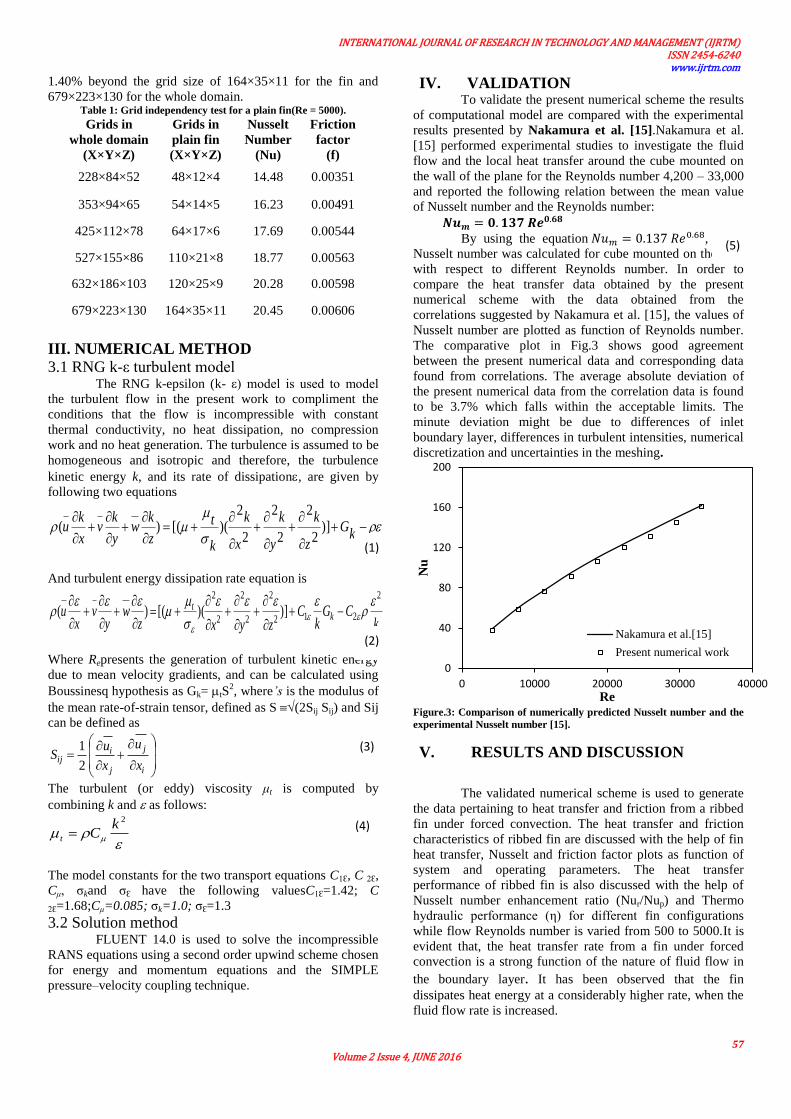
IV. VALIDATION To validate the present numerical scheme the results
of computational model are compared with the experimental
results presented by Nakamura et al. [15].Nakamura et al.
[15] performed experimental studies to investigate the fluid
flow and the local heat transfer around the cube mounted on
the wall of the plane for the Reynolds number 4,200 – 33,000
and reported the following relation between the mean value
of Nusselt number and the Reynolds number:
By using the equation , mean
Nusselt number was calculated for cube mounted on the wall
with respect to different Reynolds number. In order to
compare the heat transfer data obtained by the present
numerical scheme with the data obtained from the
correlations suggested by Nakamura et al. [15], the values of
Nusselt number are plotted as function of Reynolds number.
The comparative plot in Fig.3 shows good agreement
between the present numerical data and corresponding data
found from correlations. The average absolute deviation of
the present numerical data from the correlation data is found
to be 3.7% which falls within the acceptable limits. The
minute deviation might be due to differences of inlet
boundary layer, differences in turbulent intensities, numerical
discretization and uncertainties in the meshing.
Figure.3: Comparison of numerically predicted Nusselt number and the
experimental Nusselt number [15].
V. RESULTS AND DISCUSSION
The validated numerical scheme is used to generate
the data pertaining to heat transfer and friction from a ribbed
fin under forced convection. The heat transfer and friction
characteristics of ribbed fin are discussed with the help of fin
heat transfer, Nusselt and friction factor plots as function of
system and operating parameters. The heat transfer
performance of ribbed fin is also discussed with the help of
Nusselt number enhancement ratio (Nur/Nup) and Thermo
hydraulic performance (η) for different fin configurations
while flow Reynolds number is varied from 500 to 5000.It is
evident that, the heat transfer rate from a fin under forced
convection is a strong function of the nature of fluid flow in
the boundary layer. It has been observed that the fin
dissipates heat energy at a considerably higher rate, when the
fluid flow rate is increased.
0
40
80
120
160
200
0 10000 20000 30000 40000
Nu
Re
Nakamura et al.[15]
Present numerical work
(1)
(2)
(3)
(4)
(5)

INTERNATIONAL JOURNAL OF RESEARCH IN TECHNOLOGY AND MANAGEMENT (IJRTM) ISSN 2454-6240 www.ijrtm.com
58 Volume 2 Issue 4, JUNE 2016
Figure.4: Variation of fin heat transfer rate with Reynolds number for
different relative rib pitch (P/E) at e = 1mm.
It is believed that the application of tabulators in the form of
ribs or any other form of surface irregularity such as grooves
or perforations promotes disturbance near the wall and
thereby yields higher heat transfer rates at the cost of
additional pressure drop. Fig.4. shows the fin heat transfer
rate as function of flow Reynolds number for different values
of rib pitch to rib height ratio corresponding to rib height of 1
mm. It can be observed that the values of heat transfer rate
are found to increase with increasing the value of Reynolds
number in all cases. Plot reveals that the ribbed fin yields
considerable higher heat transfer than that of a plain fin. The
vortices induced around the square ribs and the overall
increase in surface area of the fin is responsible for the
enhanced heat transfer rates. The heat transfer rate increases
as the relative rib pitch (P/e) decreases.
The effect of relative rib pitch (P/e) on the heat
transfer rate from ribbed fin surface is shown in Fig.5. The
maximum heat transfer corresponds to the relative rib pitch
(P/e) of 4 that produces notable increase in heat transfer in
comparison to the plain fin at all values of Reynolds number.
Fig.6 shows the variation of Nusselt number as the Reynolds
number is varied between 500-5,000 for different values of
relative rib pitch (P/e) along with the plain fin for
comparative study.
Figure.5: Variation of fin heat transfer rate with Relative Rib Pitch (P/e)
for different Reynolds number at e = 1mm.
Considerable jump in the Nusselt number values can be seen
in all the cases as compared to the plain fin. To understand
the variation of Nusselt Number, with the change in relative
rib pitch (P/e), Fig.7is plotted. It can be seen that at all the
values of Reynolds number, the Nusselt number increases
with the increase in the value of relative rib pitch up to 6,
beyond which, it decreases with further increase in relative
rib pitch.
It is believed that the repeated ribs over the surface
cause flow separations and reattachments which leads to the
substantial change in the local heat transfer rates. Previous
studies show that the maximum heat transfer occurs at the
vicinity of reattachment point where boundary layer begins to
grow before the succeeding rib is reached. This may have
resulted in the observation of the maximum value of the
Nusselt number at a certain value of relative rib pitch.
Figure.6: Variation of fin Nusselt number with Reynolds number for
different relative rib pitch (P/E) at e = 1 mm.
With a view to understand the heat transfer characteristics of
a ribbed fin, temperature contours for relative rib pitch of 6
are shown in Figs.8 and 9. It can be observed that the
temperature of ribbed fin surface towards the leading end is
on lower side. It is due to the fact that the cold air stream
experiences higher temperature gradient while approaching
the leading edge of fin and, thereby, observes higher heat
transfer rates. Careful study of temperature contours unfolds
that the lowest values of temperature are found somewhere in
between the two ribs apart from the leading edge of the fin.
The higher heat removal rate in between two ribs can be
attributed to the reattachment of flow to the fin surface;
moreover, there is a local contribution to the heat removal by
the vortices originating from the rib roughness. Fig.10shows
the effect of flow Reynolds number on friction factor with
regard to different relative rib pitch (P/e).The plot shows that
the friction factor decreases as the flow Reynolds number is
increased for all fin geometries because of thinning of viscous
sub layer as Reynolds number approaches to higher values.
0
2
4
6
8
10
12
0 1000 2000 3000 4000 5000 6000
Q
Re
Plain Fin
P/e=10
P/e=8
P/e=6
P/e=4
e =1 mm
0
2
4
6
8
10
12
2 4 6 8 10 12
Q
P/e
Re=5000 Re=4500 Re=4000 Re=3500 Re=3000
Re=2500 Re=2000 Re=1500 Re=1000 Re=500
e =1 mm
0
5
10
15
20
25
0 1000 2000 3000 4000 5000 6000
Nu
Re
Plain
FinP/e=10
P/e=8
e =1 mm

INTERNATIONAL JOURNAL OF RESEARCH IN TECHNOLOGY AND MANAGEMENT (IJRTM) ISSN 2454-6240 www.ijrtm.com
59 Volume 2 Issue 4, JUNE 2016
Figure.7: Variation of fin Nusselt Number with Relative Rib Pitch (P/e)
for different Reynolds number at e = 1 mm.
Figure.8: Front view of a ribbed fin showing temperature contours.
(e=1mm; P/e = 6; Re=5000)
Figure.9: Top view of a ribbed fin showing temperature contours. (e = 1
mm; P/e = 6; Re=5000)
It can be seen that there is a substantial enhancement caused
as a result of providing rib roughness in the form of square-
rib oriented in a transverse direction. Notable increase in the
friction factor can be observed for the ribbed fin as compared
to a plain fin subjected to similar operating conditions.
Figure.10: Variation of fin Friction factor with Reynolds number for
different relative rib pitch (P/e) at e = 1 mm
Figure.11: Velocity contour of the plain fin at Re=5000
Figure.12: Velocity contour of a ribbed fin (e = 1 mm; P/e = 6; Re=5000)
Figs.11 and 12 show the comparison between theflows over
the plain fin and the ribbed fin profile,there is a stream line
flow over the plain fin whereas the flow is seen to be
separated at the rib which appears to be reattached with the
surface in the vicinity of succeeding rib. It is seen that the
separated boundary layer behind the rib results in a dead zone
by forming the vortex near the rib which reduces the heat
transfer through this area. Fig.13. shows the vector contour,
the direction of movement of stream clearly indicating the
formation of dead zone and reattach contour at the vicinity of
succeeding rib.
0
5
10
15
20
25
2 4 6 8 10 12
Nu
P/e
Re=5000 Re=4500 Re=4000 Re=3500 Re=3000
Re=2500 Re=2000 Re=1500 Re=1000 Re=500
e =1 mm
0
0.005
0.01
0.015
0.02
0.025
0 1000 2000 3000 4000 5000 6000
f
Re
Plain Fin
P/e=10
P/e=8
P/e=6
P/e=4
e=1 mm
INTERNATIONAL JOURNAL OF RESEARCH IN TECHNOLOGY AND MANAGEMENT (IJRTM) ISSN 2454-6240 www.ijrtm.com
60 Volume 2 Issue 4, JUNE 2016
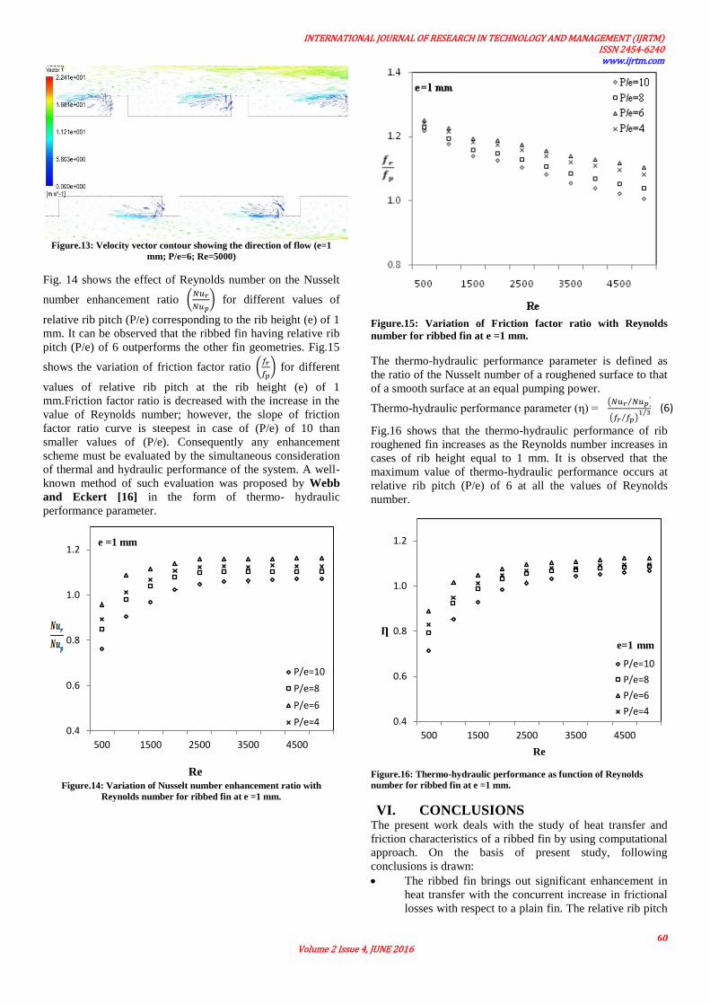
Figure.13: Velocity vector contour showing the direction of flow (e=1
mm; P/e=6; Re=5000)
Fig. 14 shows the effect of Reynolds number on the Nusselt
number enhancement ratio (
) for different values of
relative rib pitch (P/e) corresponding to the rib height (e) of 1
mm. It can be observed that the ribbed fin having relative rib
pitch (P/e) of 6 outperforms the other fin geometries. Fig.15
shows the variation of friction factor ratio (
) for different
values of relative rib pitch at the rib height (e) of 1
mm.Friction factor ratio is decreased with the increase in the
value of Reynolds number; however, the slope of friction
factor ratio curve is steepest in case of (P/e) of 10 than
smaller values of (P/e). Consequently any enhancement
scheme must be evaluated by the simultaneous consideration
of thermal and hydraulic performance of the system. A well-
known method of such evaluation was proposed by Webb
and Eckert [16] in the form of thermo- hydraulic
performance parameter.
Figure.14: Variation of Nusselt number enhancement ratio with
Reynolds number for ribbed fin at e =1 mm.
Figure.15: Variation of Friction factor ratio with Reynolds
number for ribbed fin at e =1 mm.
The thermo-hydraulic performance parameter is defined as
the ratio of the Nusselt number of a roughened surface to that
of a smooth surface at an equal pumping power.
Thermo-hydraulic performance parameter (η) = ( ⁄ )
( ⁄ )
Fig.16 shows that the thermo-hydraulic performance of rib
roughened fin increases as the Reynolds number increases in
cases of rib height equal to 1 mm. It is observed that the
maximum value of thermo-hydraulic performance occurs at
relative rib pitch (P/e) of 6 at all the values of Reynolds
number.
Figure.16: Thermo-hydraulic performance as function of Reynolds
number for ribbed fin at e =1 mm.
VI. CONCLUSIONS The present work deals with the study of heat transfer and
friction characteristics of a ribbed fin by using computational
approach. On the basis of present study, following
conclusions is drawn:
The ribbed fin brings out significant enhancement in
heat transfer with the concurrent increase in frictional
losses with respect to a plain fin. The relative rib pitch
0.4
0.6
0.8
1.0
1.2
500 1500 2500 3500 4500
Re
P/e=10
P/e=8
P/e=6
P/e=4
e =1 mm
0.4
0.6
0.8
1.0
1.2
500 1500 2500 3500 4500
Re
P/e=10
P/e=8
P/e=6
P/e=4
Ƞ
e=1 mm
(6)

INTERNATIONAL JOURNAL OF RESEARCH IN TECHNOLOGY AND MANAGEMENT (IJRTM) ISSN 2454-6240 www.ijrtm.com
61 Volume 2 Issue 4, JUNE 2016
(P/e) of 6 showed nearly two folds enhancement in the
heat transfer as compared to the plain fin performance.
The Nusselt number increases and friction factor
decreases with an increase in the values of Reynolds
number for all cases. The maximum enhancement in
the Nusselt number and the friction factor corresponds
to the relative rib pitch (P/e) of 6.
The thermo-hydraulic performance parameter of rib
roughened fin attains its maximum value
corresponding to the rib pitch of 6.
Nomenclature
Ab Cross-section area of the base plate
Af Cross-section area of the fin
Cp Specific heat
Cp,Al Specific heat of aluminium
D Fin thickness
Dh Equivalent hydraulic diameter of duct
e Height of the rib
f Friction factor
h Convective heat-transfer coefficient
hf Fin height
hp Height of perforation
kAl Thermal conductivity of aluminium
k Turbulent kinetic energy
Pr Prandtl number
Q Heat transfer rate to air
R Residual
Re Reynolds number
t Time
T Temperature
Tin = T∞ Mean plate temperature
Wp Width of perforation
uin = u∞ Inlet velocity of air
X,Y,Z rectangular coordinate
P/e Relative rib pitch
Greek symbols
α Under-relaxation factor
Δ Difference
µ Dynamic viscosity
ρ Density of air at bulk mean air
temperature
Φ General variable
The vector differential operator
ε turbulent dissipation rate
η Thermo hydraulic performance
REFERENCES [1] Han J. C., Glicksmanan L.R. and Rohsenow W. M. “An
investigation of heat transfer and friction for rib-roughened
surfaces”, Int. J. Heat & Mass Transfer, Vol. 21; pp. 1143-1156 [2] Rongguang Jia, Masoud Rokni and Bengt Sunde´n
“Impingement cooling in a rib-roughened channel with cross-
flow”, International Journal of Numerical Methods for Heat & Fluid Flow, Vol. 11; No. 7, pp. 642-662 (2001).
[3] Iaccarino G., Ooi A. and Durbin P.A. , Behnia M. “Conjugate
heat transfer predictions in two-dimensional ribbed passages”, International Journal of Heat and Fluid Flow, Vol. 23; pp 340–
345 (2002).
[4] Ligrani P. M. and Mahmood G. I. “Spatially Resolved Heat
Transferand Friction Factors in aRectangular Channel With 45-Deg Angled Crossed-Rib Turbulators”, ASME, Vol. 125; Issue
July, pp 575-584 (2003).
[5] Xiufang Gao and Bengt Sunde´n “Effects of Inclination Angle of Ribs on the Flow Behavior in Rectangular Ducts”, ASME
Vol. 126; Issue July, pp 692-699 (2004).
[6] Gupta M.K. and Kaushik S.C. “Performance evaluation of solar
air heater for various artificial roughness geometries based on
energy, effective and exergy efficiencies”, Renewable Energy,
Vol.34; pp 465–476 (2009). [7] Bilen K., Yapici S. and Celik C., "A Taguchi approach for
investigation of heat transfer from a surface equipped with
rectangular blocks", Energy Convers Manage, Vol.42; pp 951–961, (2001).
[8] Layek Apurba. “Optimal thermo-hydraulic performance of solar air heater having chamfered rib-groove roughness on absorber
plate”, IJEE, Vol. 1; Issue 4, pp 683-696 (2010).
[9] Shaeri, M.R., Yaghoubi, M., “Heat transfer analysis of lateral
ribbed fin heat sinks”, Applied Energy, Vol.86; pp 2019–2029,
(2009). [10] Patel I.H. and Borse Sachin.L. “Experimental investigation of
heat transfer enhancement over the dimpled surface”, IJEST,
Vol. 4; Issue.08, August pp 3666-3672 (2012). [11] Seo P. D. “Experimental and numerical study of laminar forced
convection heat transfer for a dimpled heat sink”,A Thesis
Submitted to the Office of Graduate Studies of Texas A&M University (2007).
[12] Yadav Anil Singh and Bhagoria J. L. “Modeling and Simulation of turbulent flows through a solar air heater having square-
sectioned transverse rib roughness on the absorber plate”, The
Scientific World Journal Volume, Article ID 827131 (2013). [13] Jörg Franke, Antti Hellsten, Heinke Schlünzen, and Bertrand
Carissimo“Best practice guideline for the CFD simulation of
flows” COST Action 732 , (2007). [14] Leung C.W, Probert S.D., "Heat exchanger performance: effect
of orientation", Appl Energy, Vol. 55; pp 33:35, (1989).
[15] Nakamura H., Igarashi T. and Tasutsui T., “Local heat transfer
around wall-mounted cube in the turbulent boundary layer” Int.
J. Heat & Mass Transfer, Vol. 44; pp. 3385-3395 (2001).
[16] Webb R. L., and Eckert R.G, “Application of rough surfaces to heat exchanger design,” International Journal of Heat and
MassTransfer, Vol. 15, Issue. 9, pp. 1647–1658, 1972.