Internal Loadings Developed in Structural...
44
Internal Loadings Developed in Structural Members THEORY OF STRUCTURES Asst. Prof. Dr. Cenk Üstündağ
Transcript of Internal Loadings Developed in Structural...
Internal Loadings Developed in Structural Members
THEORY OF STRUCTURES
Asst. Prof. Dr. Cenk Üstündağ

Internal loadings at a specified point
The internal load at a specified point in a member can be determined by using the method of sections
This consists of: N, normal force V, shear force M, bending moment

Internal loadings at a specified point
Sign convention Although the choice is arbitrary, the convention has been
widely accepted in structural engineering
Internal loadings at a specified point
Procedure for analysis Determine the support reactions before the member is “cut” If the member is part of a pin-connected structure, the pin
reactions can be determine using the methods of section Keep all distributed loadings, couple moments & forces acting
on the member in their exact location
Internal loadings at a specified point
Pass an imaginary section through the member, perpendicular to its axis at the point where the internal loading is to be determined
Then draw a free-body diagram of the segment that has the least no. of loads on it
Indicate the unknown resultants N, V & M acting in their positive directions

Internal loadings at a specified point
Moments should be summed at the section about axes that pass through the centroid of the member’s x-sectional area in order to eliminate N & V, thereby solving M
If the solution of the equilibrium equations yields a quantity having a negative magnitude, then the assumed directional sense of the quantity is opposite to that shown on the free-body diagram

Example
The building roof shown in the photo has a weight of 1.8 kN/m2
and is supported on 8m long simply supported beams that are spaced 1 m apart. Each beam as shown transmits its loading to two girders, located at the front and back of the building. Determine the internal shear and moment in the front girder at point C. Neglect the weight of the members.

Solution
Roof loading is transmitted to each beam as a one-way slab (L2/L1 =8>2)Tributary load on each interior beam = (1.8 kN/m2)(1 m) = 1.8 kN/mReaction on girder = (1.8 kN/m)(8 m)/2 = 7.2 kNThe two edge beams support 0.9 kN/m

Solution
Each column reaction is [12(3.6 kN) + 11(7.2 kN)]/2 = 43.2 kN
m•kN2.30
02.12.43)4.2(6.3)4.1(25.7)4.0(2.70
positive, as clockwise-anti in the momentsWith
kN2.2502.726.32.43
;0
c
C
C
CC
y
MM
M
VV
F

Example
Determine the internal shear & moment acting in the cantilever beam at sections passing through C & D.
Solution
If we consider free-body diagrams of segments to the right of the sections, the support reactions at A do not have to be calculated.
kNmMMM
kNVVF
S
ccc
cc
y
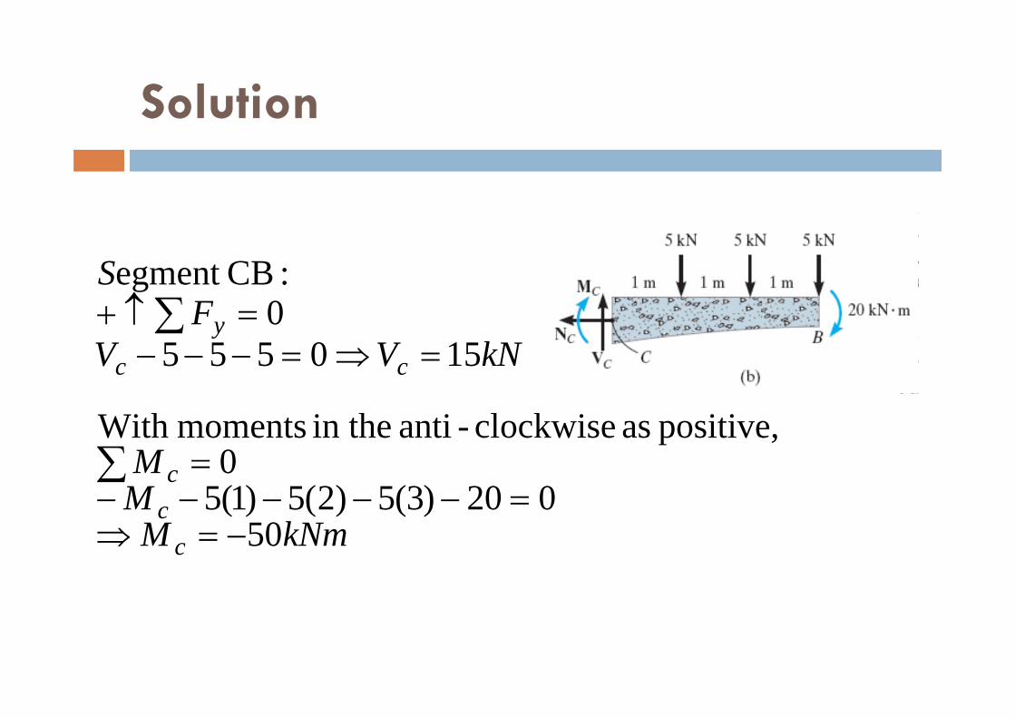
50020)3(5)2(5)1(5
0positive, as clockwise-anti in the momentsWith
1505550:CBegment

Solution
kNmMMM
kNVVF
S
DDD
DD
y
50020)3(5)2(5)1(5
0positive, as clockwise-anti in the momentsWith
20055550:DBegment
Shear & Moment Functions
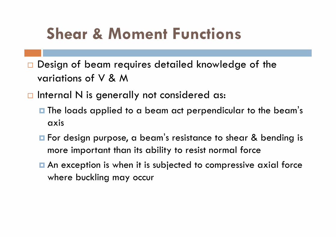
Design of beam requires detailed knowledge of the variations of V & M
Internal N is generally not considered as: The loads applied to a beam act perpendicular to the beam’s
axis For design purpose, a beam’s resistance to shear & bending is
more important than its ability to resist normal force An exception is when it is subjected to compressive axial force
where buckling may occur

Shear & Moment Functions
In general, the internal shear & moment functions will be discontinuous or their slope will discontinuous at points where: The type or magnitude of the distributed load changes Concentrated forces or couple moments are applied

Shear & Moment Functions
Procedure for Analysis Determine the support reactions on the beam Resolve all the external forces into components acting
perpendicular & parallel to beam’s axis Specify separate coordinates x and associated origins,
extending into: Regions of the beam between concentrated forces and/or couple
moments Discontinuity of distributed loading

Shear & Moment Functions
Procedure for Analysis Section the beam perpendicular to its axis at each distance x From the free-body diagram of one of the segments,
determine the unknowns V & M On the free-body diagram, V & M should be shown acting in
their positive directions V is obtained from M is obtained by
0 yF0 sM

Shear & Moment Functions
Procedure for Analysis The results can be checked by noting that:
wdxdV
Vdx
dM

Example
Determine the shear & moment in the beam as a function of x.
Solution
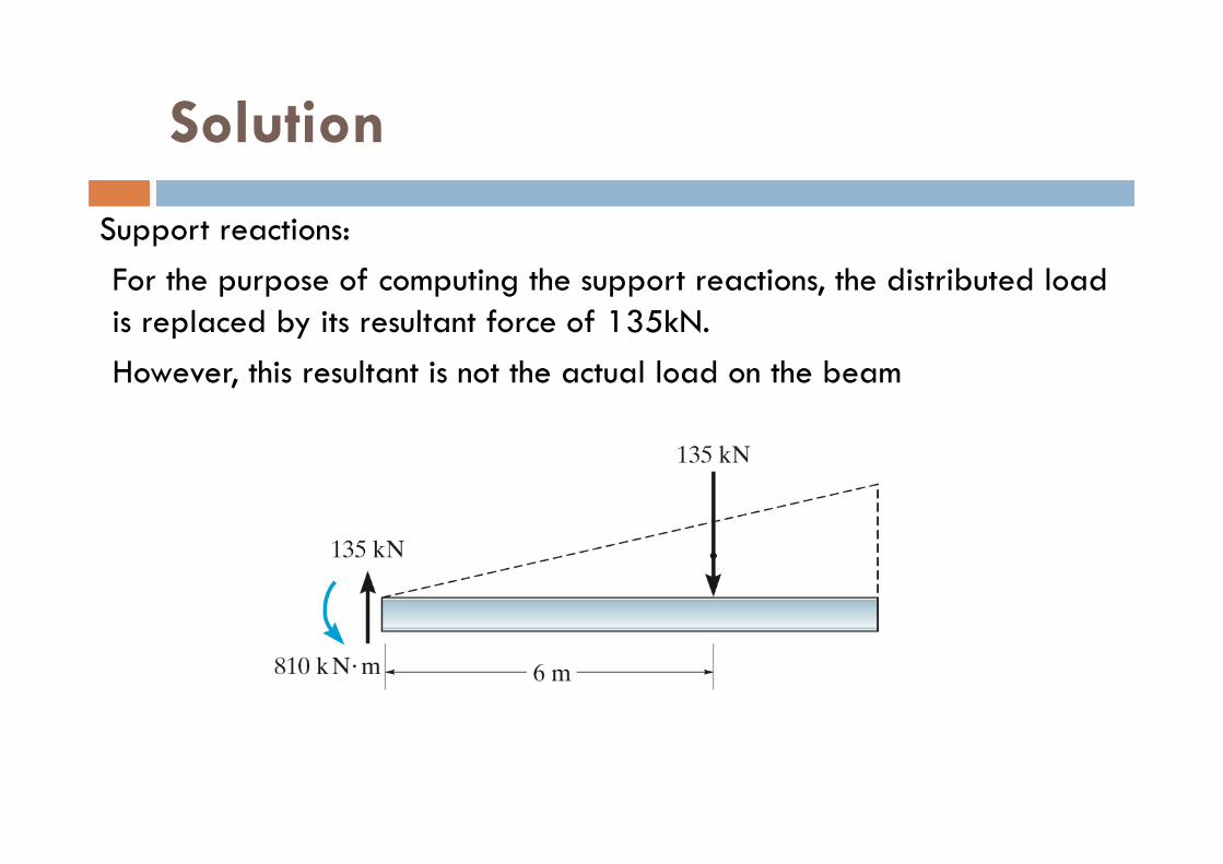
Support reactions:For the purpose of computing the support reactions, the distributed load is replaced by its resultant force of 135kN.However, this resultant is not the actual load on the beam

Solution
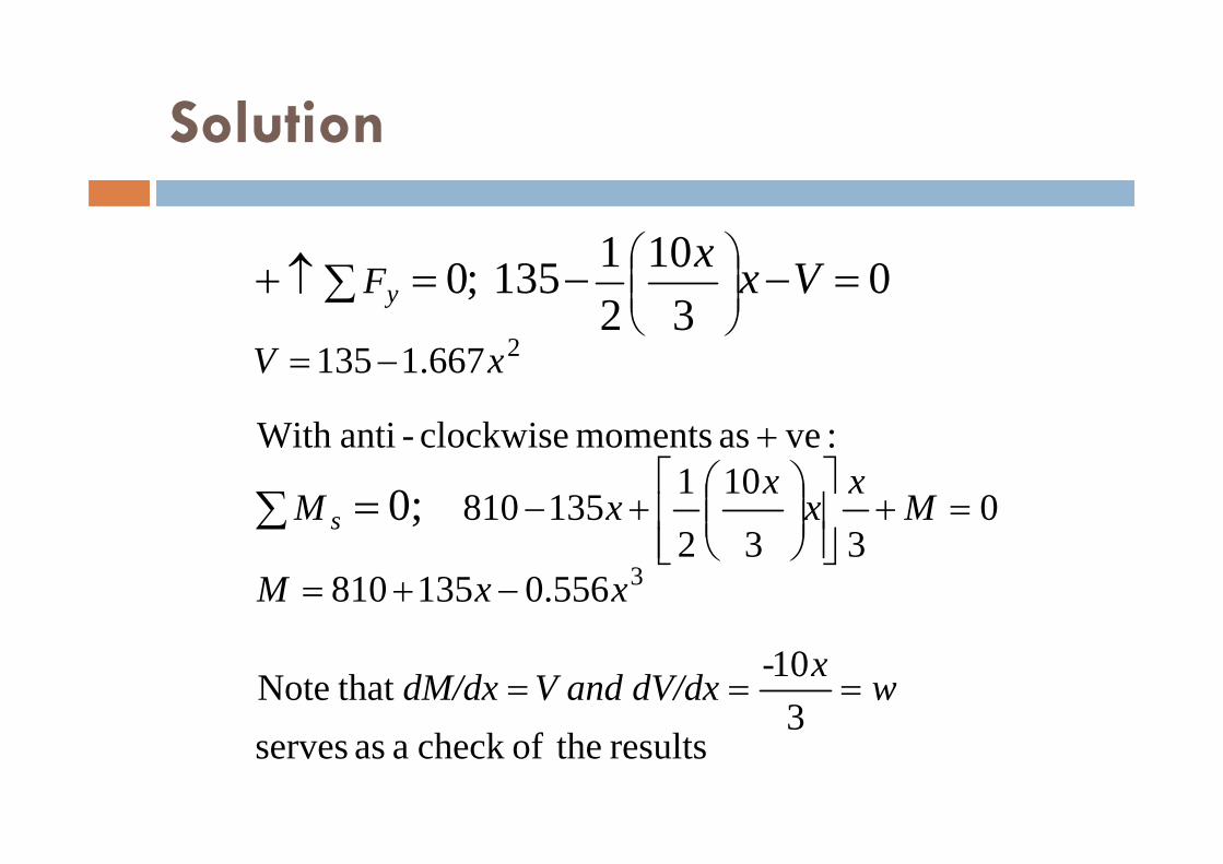
Shear & moment functionsA free-body diagram of the beam segment of length x is shown. Note that the intensity of the triangular load at the section is found by proportion.With the load intensity known, the resultant of the distributed load is found in the usual manner.
Solution
results theofcheck a as serves
310 that Note
556.0135810
033
10
2
1135810
:ve as moments clockwise-antiWith
667.1135
3
2
0;
03
1021135 ;0
wx-xV and dV/ddM/dx
xxM
Mx
xx
xM
xV
F
s
y Vxx
Shear & Moment Diagrams for a Beam
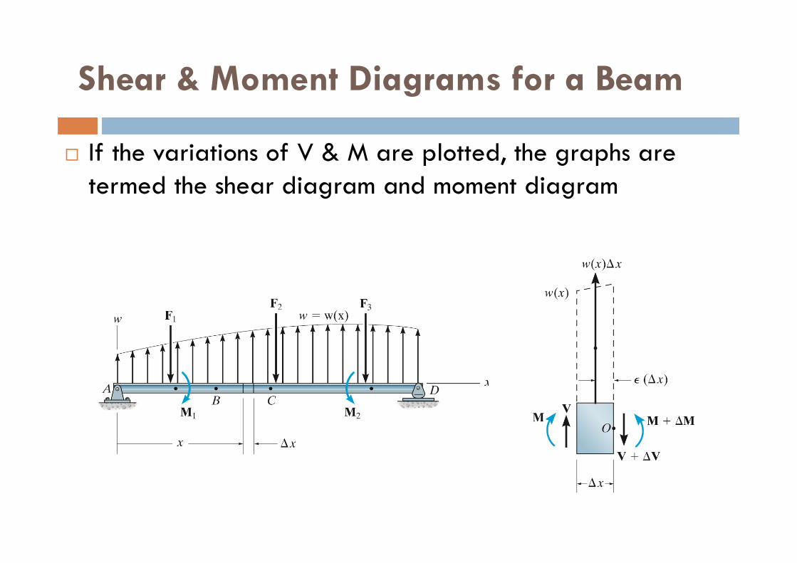
If the variations of V & M are plotted, the graphs are termed the shear diagram and moment diagram

Shear & Moment Diagrams for a Beam
Applying the equation of equilibrium, we have:
2)()(0)()()(
:ve as moments clockwise-antiWith
)(0)()(
;0
;0
xxwxVMMMxxxwMxV
M
xxwVVVxxwV
F
o
y
Shear & Moment Diagrams for a Beam
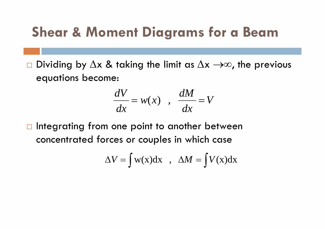
Dividing by x & taking the limit as x , the previous equations become:
Integrating from one point to another between concentrated forces or couples in which case
Vdx
dMxwdxdV
, )(
(x)dx , w(x)dx VMV
Shear & Moment Diagrams for a Beam
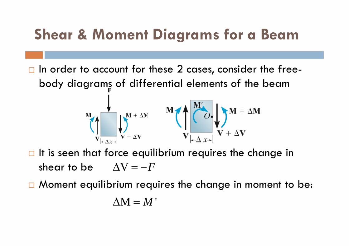
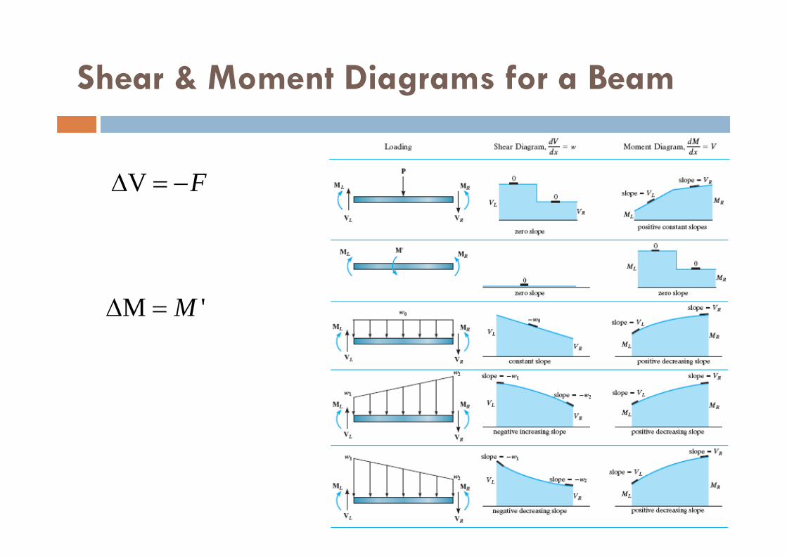
FV
'M M
In order to account for these 2 cases, consider the free-body diagrams of differential elements of the beam
It is seen that force equilibrium requires the change in shear to be
Moment equilibrium requires the change in moment to be:
Shear & Moment Diagrams for a Beam
FV
'M M

Example
Draw the shear & moment diagrams for the beam.

Solution
At end points:x = 0m, V = 30kNx = 9m, V = -60kN
The load w is –ve & linearly increasing, dV/dx=w
The point of zero shear can be found by using method of sections from a beam segment of length x,
mx
xxF
V
y
20.5
09
2021300
0
Solution
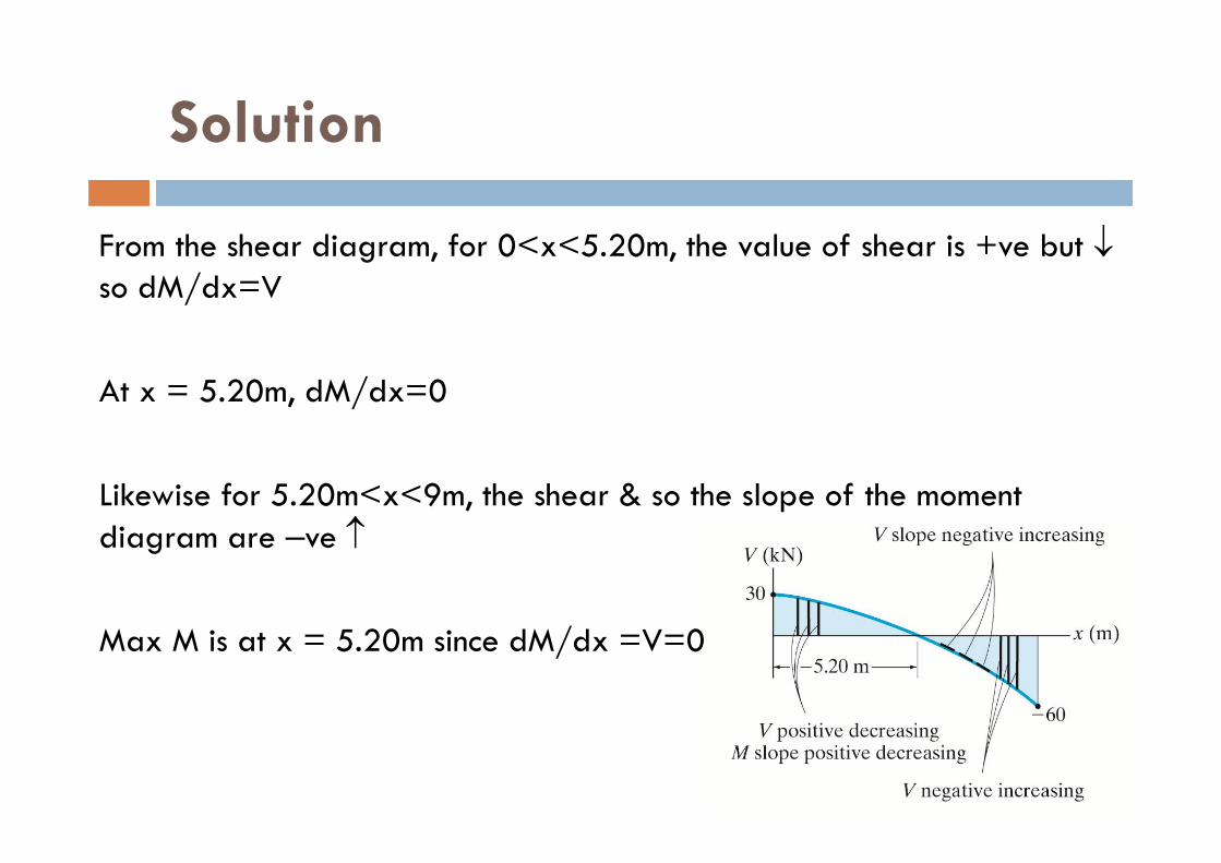
From the shear diagram, for 0<x<5.20m, the value of shear is +ve but so dM/dx=V
At x = 5.20m, dM/dx=0
Likewise for 5.20m<x<9m, the shear & so the slope of the moment diagram are –ve
Max M is at x = 5.20m since dM/dx =V=0

Solution
We have,
kNmM
M
M s
104
0320.520.5
920.520
21)20.5(30
0:ve- asmoment iseAnticlockw

Moment Diagrams Constructed by the Method of Superposition
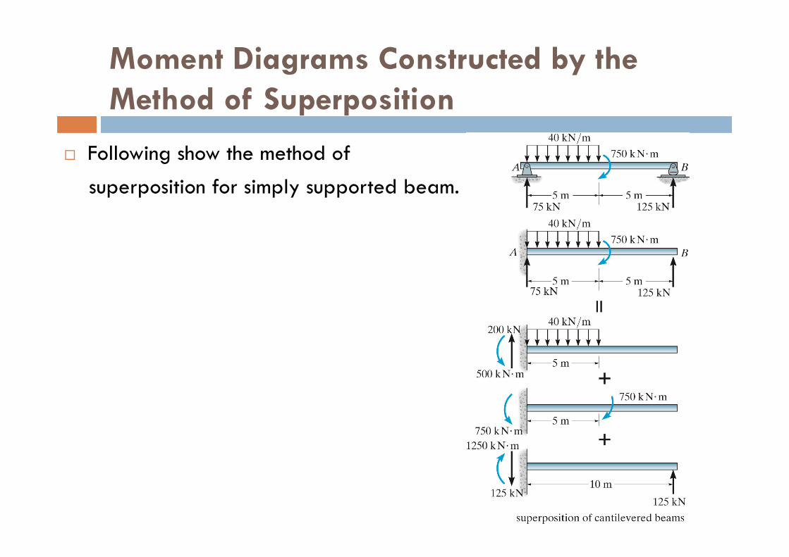
Beams are used primarily to resist bending stress, it is important that the moment diagram accompany the solution for their design.
Most loadings on beams in structural analysis will be a combination of the loadings as shown.

Moment Diagrams Constructed by the Method of Superposition
Moment Diagrams Constructed by the Method of Superposition
Following show the method of superposition for simply supported beam.

Multispan hinged beams(Cantilevered beams or Gerber beams)
Multispan hinged beams (Gerber beams) are geometrically unchangeable and statically determinate structures consisting of a series of one-span beams with or without overhangs connected together by means of hinges.

Gerber beam
Multispan hinged beams are designated after German engineer Heinrich Gottfried Gerber (1832-1912), who got on it 1866 a patent.
Forth Bridge in Scotland
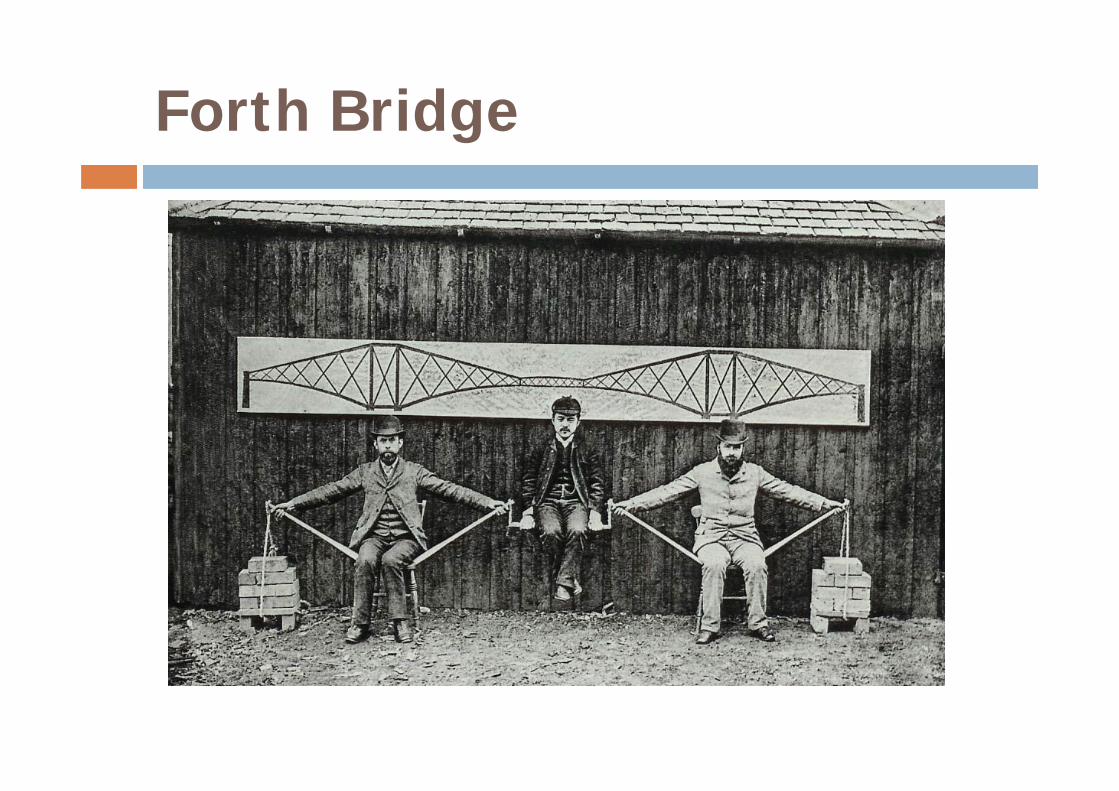
Forth Bridge

Generation of Multispan Statically Determinate Hinged Beams
The following rules of distribution of hinges in beams, which have no clamped ends, provide their unchangeableness and statical determinacy: Each span may contain no more than two hinges. Spans with two hinges must alternate with spans without
hinges. Spans with one hinge may follow each other, providing that
first (or last) span has no hinges. One of support has to prevent movement in the horizontal
direction.

Distribution of hinges in beams with simply supported ends
The distinctive properties of multispan statically determinate beams: Structure with intermediate hinges has less stiffness than
structure without intermediate hinges. This leads to substantial reduction of bending moments as compared with continuous beams spanning the same opening.
Possibility of control stresses by variation of hinges locations.

Advantages of multispan hinged beams
Advantages of multispan hinged beams are as follows: Change of temperature, settlements of supports, imperfect
of assembly does not create stresses. Failure of one of the support may not destroy the entire
system. Relatively short members of multispan beams are well suited
for prefabrication, transportation, and installation using standard equipment.
Multispan hinged beams are usually more economical than a series of disconnected simply supported beams spanning the same opening.
Interaction Schemes and Load Path
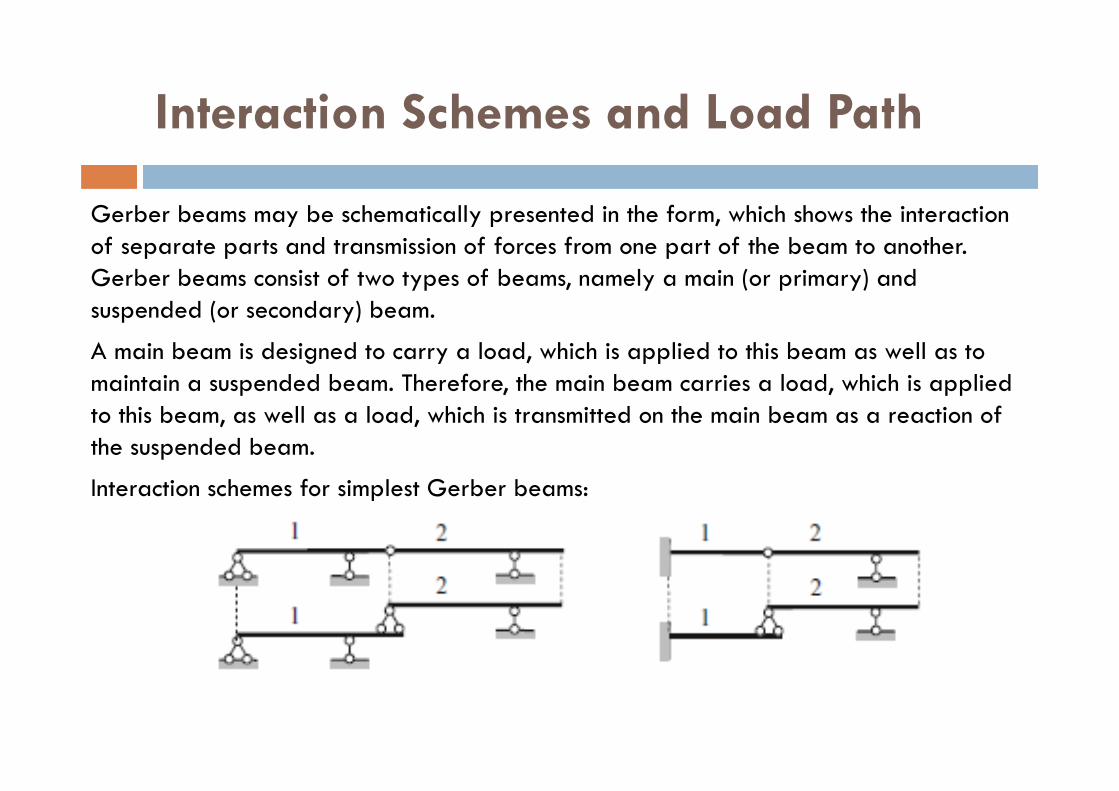
Gerber beams may be schematically presented in the form, which shows the interaction of separate parts and transmission of forces from one part of the beam to another. Gerber beams consist of two types of beams, namely a main (or primary) and suspended (or secondary) beam.
A main beam is designed to carry a load, which is applied to this beam as well as to maintain a suspended beam. Therefore, the main beam carries a load, which is applied to this beam, as well as a load, which is transmitted on the main beam as a reaction of the suspended beam.
Interaction schemes for simplest Gerber beams:
Interaction Schemes and Load Path
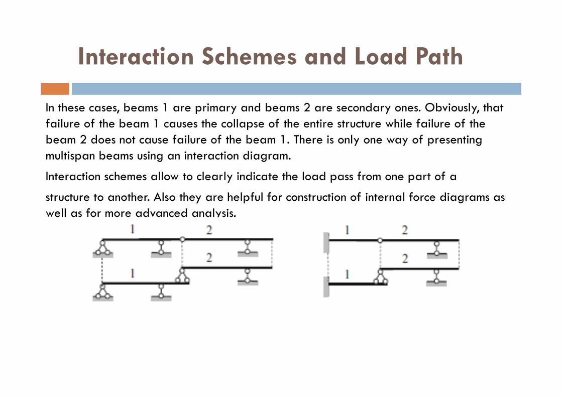
In these cases, beams 1 are primary and beams 2 are secondary ones. Obviously, that failure of the beam 1 causes the collapse of the entire structure while failure of the beam 2 does not cause failure of the beam 1. There is only one way of presentingmultispan beams using an interaction diagram.
Interaction schemes allow to clearly indicate the load pass from one part of a
structure to another. Also they are helpful for construction of internal force diagrams as well as for more advanced analysis.

Interaction Schemes and Load Path
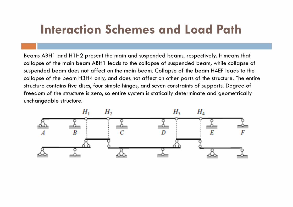
Five-span beam and its interaction diagram is presented in the figure.
Since the structure in a whole is restricted against the horizontal displacement owing to support A, then each part of the structure has no displacement in horizontal direction as well. That is why the rolled supports C and E on the interaction diagram are replaced by pinned supports. Restrictions for suspended beams also prevent horizontal displacements. This replacement is conventional.
Interaction Schemes and Load Path
Beams ABH1 and H1H2 present the main and suspended beams, respectively. It means that collapse of the main beam ABH1 leads to the collapse of suspended beam, while collapse of suspended beam does not affect on the main beam. Collapse of the beam H4EF leads to the collapse of the beam H3H4 only, and does not affect on other parts of the structure. The entire structure contains five discs, four simple hinges, and seven constraints of supports. Degree of freedom of the structure is zero, so entire system is statically determinate and geometrically unchangeable structure.

Interaction Schemes and Load Path
Another four-span beam and its interaction diagram is presented in thefigure. The entire structure contains four discs, three simple hinges, and six constraints of supports. Degree of freedom of the structure is again zero, so entire system is statically determinate and geometrically unchangeable structure.