7.2 Shear and Moment Equations and Diagrams Beams – structural members designed to support...
21
7.2 Shear and Moment Equations and Diagrams Beams – structural members designed to support loadings perpendicular to their axes Beams – straight long bars with constant cross-sectional areas A simply supported beam is pinned at one end and roller supported at the other A cantilevered beam is fixed at one end and free at the other
-
Upload
flora-boyd -
Category
Documents
-
view
238 -
download
2
Transcript of 7.2 Shear and Moment Equations and Diagrams Beams – structural members designed to support...

7.2 Shear and Moment Equations
and Diagrams
7.2 Shear and Moment Equations
and Diagrams Beams – structural members designed to
support loadings perpendicular to their axes Beams – straight long bars with constant
cross-sectional areas A simply supported beam is pinned at one end
and roller supported at the other
A cantilevered beam is fixed at one end and free at the other

7.2 Shear and Moment Equations
and Diagrams
7.2 Shear and Moment Equations
and Diagrams For actual design of a beam, apply- Internal shear force V and the bending
moment M analysis- Theory of mechanics of materials- Appropriate engineering code to determine
beam’s required cross-sectional area Variations of V and M obtained by the
method of sections Graphical variations of V and M are termed
as shear diagram and bending moment diagram
7.2 Shear and Moment Equations
and Diagrams
7.2 Shear and Moment Equations
and Diagrams Internal shear and bending moment functions generally discontinuous, or their slopes will be discontinuous at points where a distributed load changes or where concentrated forces or couple moments are applied
Functions must be applied for each segment of the beam located between any two discontinuities of loadings
Internal normal force will not be considered
7.2 Shear and Moment Equations
and Diagrams
7.2 Shear and Moment Equations
and DiagramsLoad applied to a beam act
perpendicular to the beam’s axis and hence produce only an internal shear force and bending moment
For design purpose, the beam’s resistance to shear, and particularly to bending, is more important than its ability to resist a normal force
7.2 Shear and Moment Equations
and Diagrams
7.2 Shear and Moment Equations
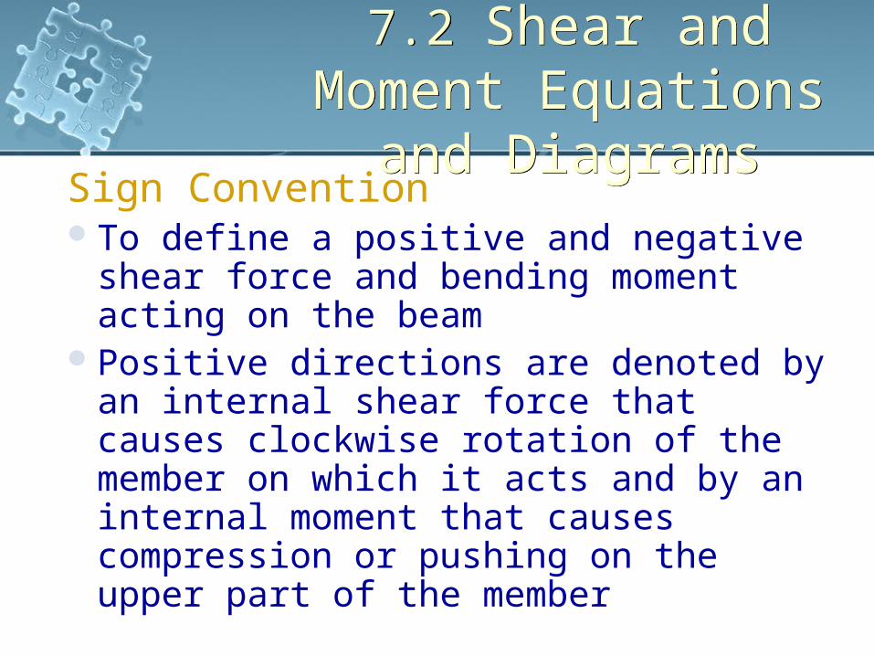
and DiagramsSign ConventionTo define a positive and negative shear
force and bending moment acting on the beam
Positive directions are denoted by an internal shear force that causes clockwise rotation of the member on which it acts and by an internal moment that causes compression or pushing on the upper part of the member
7.2 Shear and Moment Equations
and Diagrams
7.2 Shear and Moment Equations
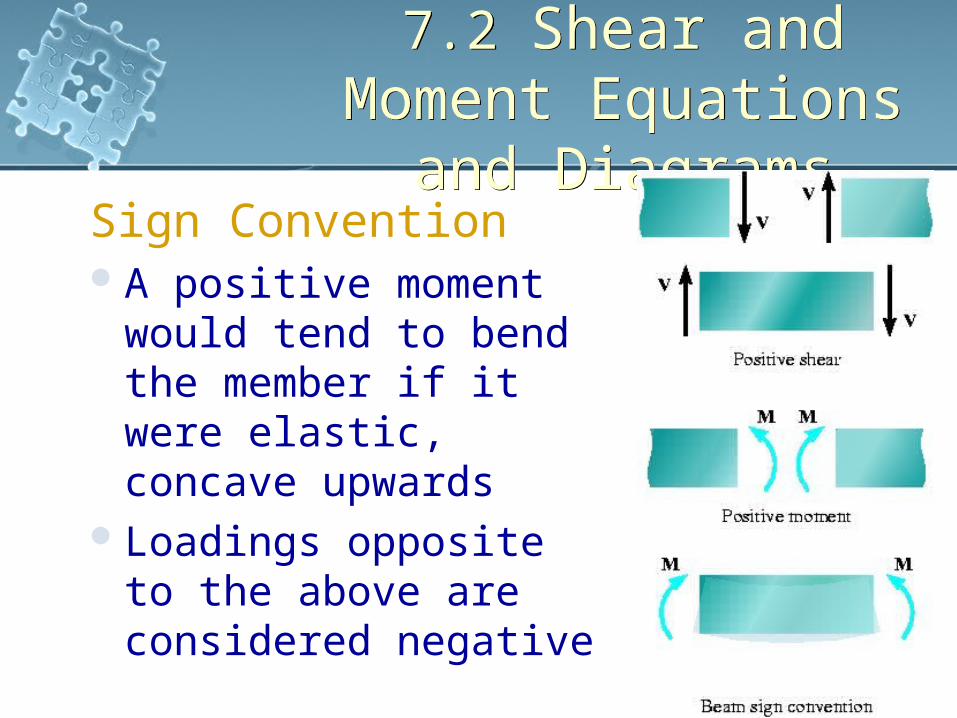
and DiagramsSign ConventionA positive moment
would tend to bend the member if it were elastic, concave upwards
Loadings opposite to the above are considered negative

7.2 Shear and Moment Equations
and Diagrams
7.2 Shear and Moment Equations
and DiagramsProcedure for AnalysisSupport ReactionsDetermine all the reactive forces and
couple moments acting on the beam’Resolve them into components
acting perpendicular or parallel to the beam’s axis

7.2 Shear and Moment Equations
and Diagrams
7.2 Shear and Moment Equations
and DiagramsProcedure for AnalysisShear and Moment Reactions Specify separate coordinates x having an
origin at the beam’s left end and extending to regions of the beams between concentrated force and/or couple moments or where there is no continuity of distributed loadings
Section the beam perpendicular to its axis at each distance x and draw the FBD of one of the segments

7.2 Shear and Moment Equations
and Diagrams
7.2 Shear and Moment Equations
and DiagramsProcedure for AnalysisShear and Moment Reactions V and M are shown acting in their positive
sense The shear V is obtained by summing the
forces perpendicular to the beam’s axis The moment M is obtained by summing
moments about the sectioned end of the segment

7.2 Shear and Moment Equations
and Diagrams
7.2 Shear and Moment Equations
and DiagramsProcedure for AnalysisShear and Moment Diagrams Plot the shear diagram (V versus x) and the
moment diagram (M versus x) If computed values of the functions
describing V and M are positive, the values are plotted above the x axis, whereas negative values are plotted below the x axis
Convenient to plot the shear and the bending moment diagrams below the FBD of the beam

7.2 Shear and Moment Equations
and Diagrams
7.2 Shear and Moment Equations
and DiagramsExample 7.7Draw the shear and bending moments diagrams for the shaft. The support at A is
a thrust bearing and the support at C is a journal bearing.

7.2 Shear and Moment Equations
and Diagrams
7.2 Shear and Moment Equations
and DiagramsSolutionSupport ReactionsFBD of the shaft

7.2 Shear and Moment Equations
and Diagrams
7.2 Shear and Moment Equations
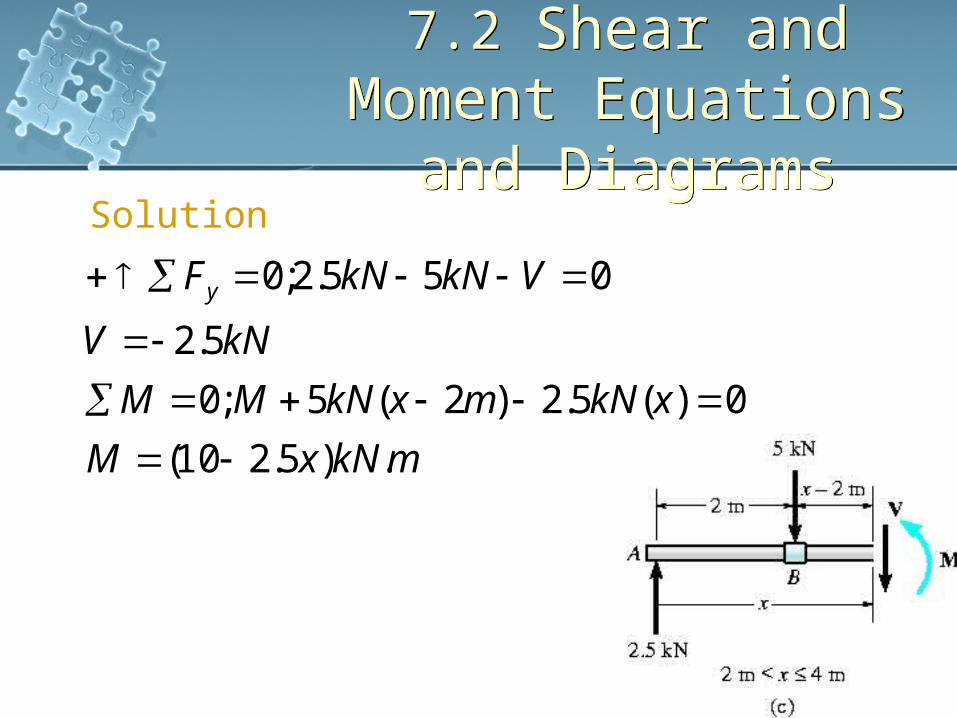
and DiagramsSolution
mxkNMM
kNVFy
.5.2;0
5.2;0
7.2 Shear and Moment Equations
and Diagrams
7.2 Shear and Moment Equations
and DiagramsSolution
mkNxM
xkNmxkNMM
kNV
VkNkNFy
.)5.210(
0)(5.2)2(5;0
5.2
055.2;0

7.2 Shear and Moment Equations
and Diagrams
7.2 Shear and Moment Equations
and DiagramsSolutionShear diagram internal shear force is always
positive within the shaft AB Just to the right of B, the
shear force changes sign and remains at constant value for segment BC
Moment diagram Starts at zero, increases
linearly to B and therefore decreases to zero

7.2 Shear and Moment Equations
and Diagrams
7.2 Shear and Moment Equations
and DiagramsSolution Graph of shear and
moment diagrams is discontinuous at points of concentrated force ie, A, B, C
All loading discontinuous are mathematical, arising from the idealization of a concentrated force and couple moment

7.2 Shear and Moment Equations
and Diagrams
7.2 Shear and Moment Equations
and DiagramsExample 7.8Draw the shear and bending diagrams for the beam.
7.2 Shear and Moment Equations
and Diagrams
7.2 Shear and Moment Equations
and Diagrams
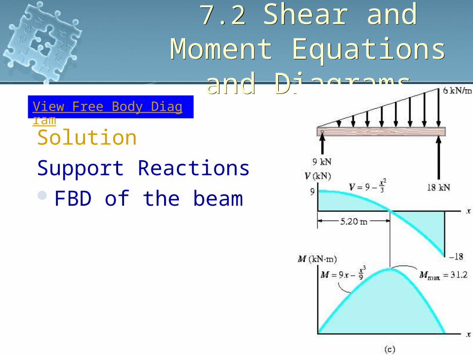
SolutionSupport ReactionsFBD of the beam
View Free Body Diagram
7.2 Shear and Moment Equations
and Diagrams
7.2 Shear and Moment Equations
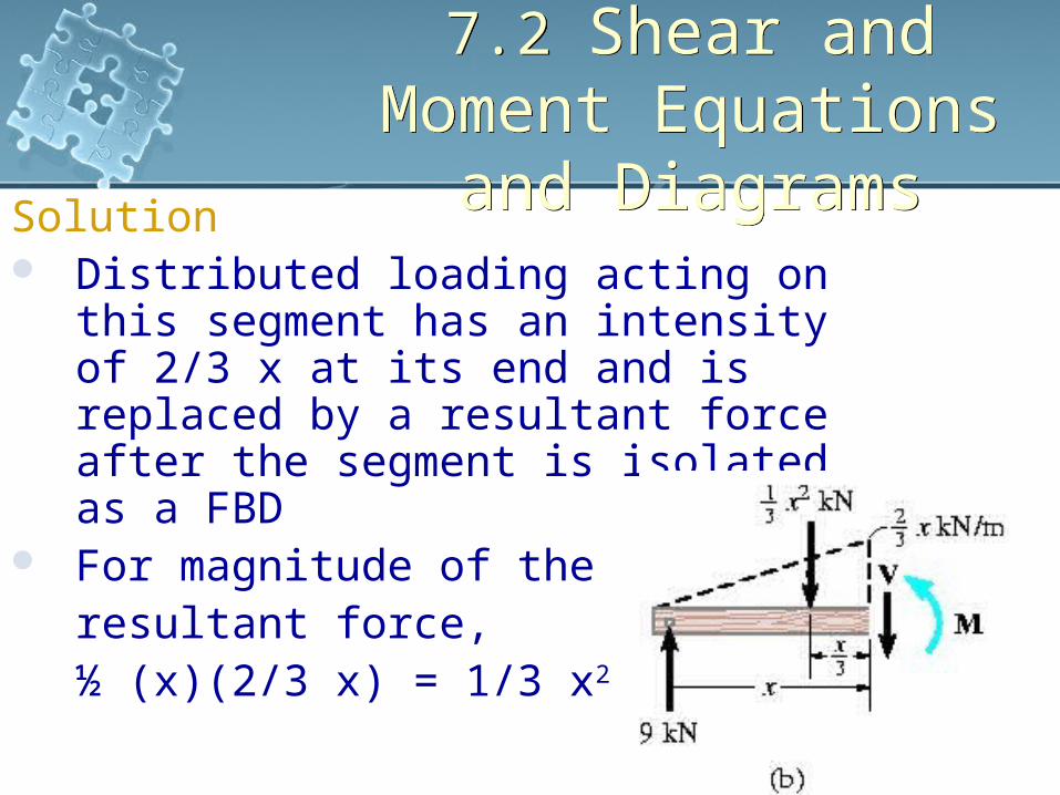
and DiagramsSolution Distributed loading acting on this
segment has an intensity of 2/3 x at its end and is replaced by a resultant force after the segment is isolated as a FBD
For magnitude of the resultant force, ½ (x)(2/3 x) = 1/3 x2

7.2 Shear and Moment Equations
and Diagrams
7.2 Shear and Moment Equations
and DiagramsSolution Resultant force acts through the centroid
of the distributed loading area, 1/3 x from the right
mkNx
xM
xx
xMM
kNx
V
VxFy
.9
9
0933
1;0
39
03
19;0
3
2
2
2

7.2 Shear and Moment Equations
and Diagrams
7.2 Shear and Moment Equations
and DiagramsSolution For point of zero shear,
For maximum moment,
mkN
mkNM
mx
xV
.12.3
.9
20.520.59
20.5
03
9
3
max
3