
Intelligent Power Devices - Renesas e-Learning · Intelligent Power Devices Smart Switches for...
35
Renesas Electronics America Inc. © 2012 Renesas Electronics America Inc. All rights reserved. Class ID: Class ID: Intelligent Power Devices Smart Switches for Automotive Exterior Lighting Keith Larson Product Marketing Manager - Analog and Power Devices 0C16I
Transcript of Intelligent Power Devices - Renesas e-Learning · Intelligent Power Devices Smart Switches for...

Renesas Electronics America Inc.
© 2012 Renesas Electronics America Inc. All rights reserved.
Class ID: Class ID:
Intelligent Power Devices Smart Switches for Automotive Exterior Lighting
Keith Larson
Product Marketing Manager - Analog and Power Devices
0C16I
© 2012 Renesas Electronics America Inc. All rights reserved. 2
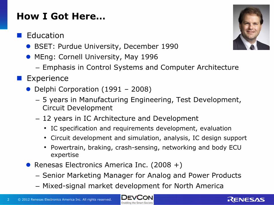
How I Got Here…
Education
BSET: Purdue University, December 1990
MEng: Cornell University, May 1996
– Emphasis in Control Systems and Computer Architecture
Experience
Delphi Corporation (1991 – 2008)
– 5 years in Manufacturing Engineering, Test Development, Circuit Development
– 12 years in IC Architecture and Development
• IC specification and requirements development, evaluation
• Circuit development and simulation, analysis, IC design support
• Powertrain, braking, crash-sensing, networking and body ECU expertise
Renesas Electronics America Inc. (2008 +)
– Senior Marketing Manager for Analog and Power Products
– Mixed-signal market development for North America

© 2012 Renesas Electronics America Inc. All rights reserved. 3
Renesas Technology & Solution Portfolio
© 2012 Renesas Electronics America Inc. All rights reserved. 4
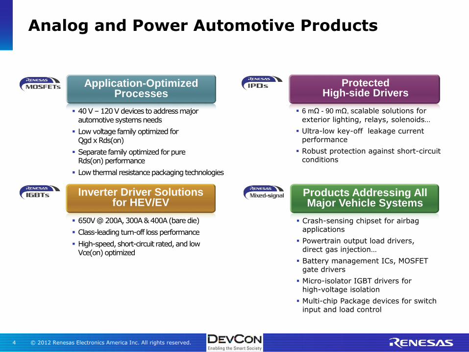
Analog and Power Automotive Products
6 mΩ - 90 mΩ, scalable solutions for
exterior lighting, relays, solenoids…
Ultra-low key-off leakage current performance
Robust protection against short-circuit conditions
650V @ 200A, 300A & 400A (bare die)
Class-leading turn-off loss performance
High-speed, short-circuit rated, and low Vce(on) optimized
40 V – 120 V devices to address major automotive systems needs
Low voltage family optimized for Qgd x Rds(on)
Separate family optimized for pure Rds(on) performance
Low thermal resistance packaging technologies
Crash-sensing chipset for airbag applications
Powertrain output load drivers, direct gas injection…
Battery management ICs, MOSFET gate drivers
Micro-isolator IGBT drivers for high-voltage isolation
Multi-chip Package devices for switch input and load control
Application-Optimized Processes
Protected High-side Drivers
Products Addressing All Major Vehicle Systems
Inverter Driver Solutions for HEV/EV

© 2012 Renesas Electronics America Inc. All rights reserved. 5
‘Enabling The Smart Society’
Challenge: “The Smart Society requires automotive systems that can reliably drive bulbs, relays, solenoids and other high-current loads without succumbing to the safety risks posed in such applications. All of this intelligence cannot come at the price of consuming energy in times when the device is not in use.”
Solution:
“Intelligent power devices provide a robust, ‘green’ solution for driving today’s demanding automotive loads and providing critical fault protection and detection from the harsh automotive environment. Efficient designs practically eliminate any off-state current drain from the vehicle energy source.”
© 2012 Renesas Electronics America Inc. All rights reserved. 6
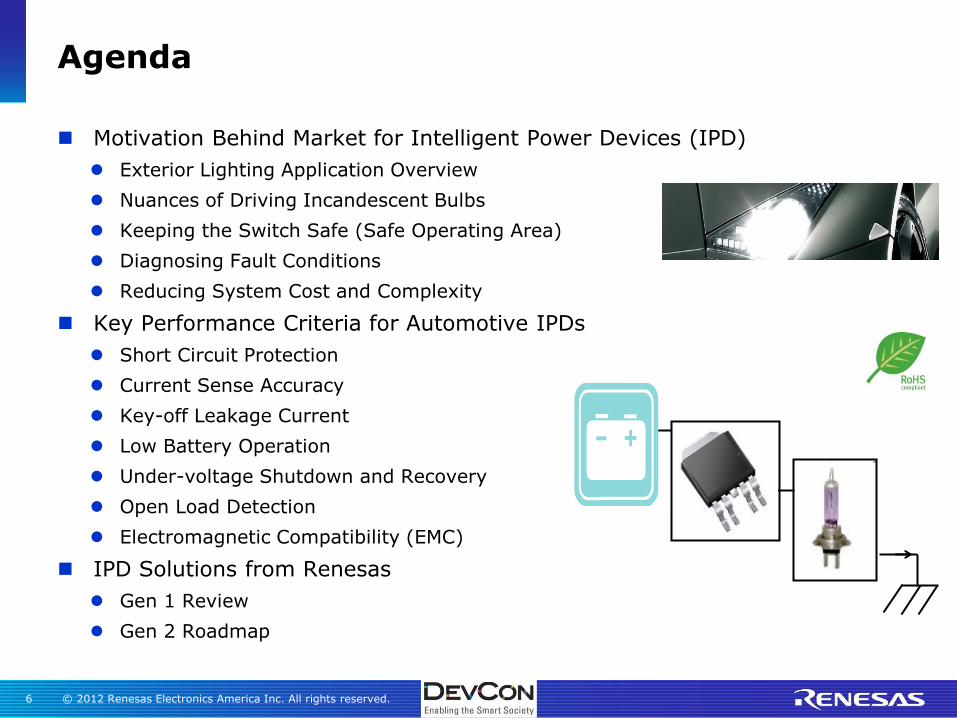
Agenda
Motivation Behind Market for Intelligent Power Devices (IPD)
Exterior Lighting Application Overview
Nuances of Driving Incandescent Bulbs
Keeping the Switch Safe (Safe Operating Area)
Diagnosing Fault Conditions
Reducing System Cost and Complexity
Key Performance Criteria for Automotive IPDs
Short Circuit Protection
Current Sense Accuracy
Key-off Leakage Current
Low Battery Operation
Under-voltage Shutdown and Recovery
Open Load Detection
Electromagnetic Compatibility (EMC)
IPD Solutions from Renesas
Gen 1 Review
Gen 2 Roadmap
VBAT

© 2012 Renesas Electronics America Inc. All rights reserved. 7
Motivation Behind Market for Intelligent Power Devices (IPD)
© 2012 Renesas Electronics America Inc. All rights reserved. 8
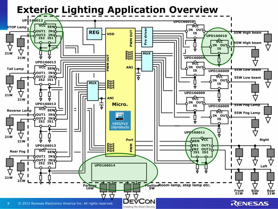
Exterior Lighting Application Overview
Micro.
REG 55W High beam
PW
M O
UT
VDD
Front 21W
Side 5W
Rear 21W
Right
Left
Port
ANI
STOP Lamp IN
VCC
IS OUT
IN VCC
IS OUT
IN VCC
IS OUT
IN VCC
IS OUT
55W High beam
55W Low beam
55W Low beam
IN VCC
IS OUT
IN VCC
IS OUT
55W Fog Lamp
55W Fog Lamp
MUX Port Port
Port
Pre d
riv
er
IN2
VCC
IS1 OUT2
IN1
IS2
OUT1
SEN
21W
21W
Tail Lamp
IN2
VCC
IS1 OUT2
IN1
IS2
OUT1
SEN
21W
21W
Reverse Lamp
IN2
VCC
IS1 OUT2
IN1
IS2
OUT1
SEN
21W
21W
Rear Fog
IN2
VCC
IS1 OUT2
IN1
IS2
OUT1
SEN
21W 21W
Port Port Port
Port
ANI
MUX
Port Port Port
Port
PW
M O
UT
UPD166010
UPD166010
UPD166009
UPD166009
UPD166009
UPD166009
UPD166011
UPD166013
UPD166013
UPD166013
UPD166013
Parking 10W
Position 5W
Room lamp, step lamp etc.
UPD166014
IN2
VCC
IS1 OUT2
IN1
IS2
OUT1
SEN
PW
M
Port

© 2012 Renesas Electronics America Inc. All rights reserved. 9
Incandescent bulbs have an ‘in-rush’ characteristic
Cold filament is low impedance
Filament heats quickly due to current
Commonly modeled as a parallel RC network
Output must be sized to survive the peak in-rush current
Cannot go into any protective operation, as this would extend the turn-on time and increase power dissipation depending on protective methods
In-rush current can be many times greater than steady-state current
Optimal protective schemes can adjust between these two operating conditions
Nuances of Driving Incandescent Bulbs
Example of a model for an
automotive grade, 168-type bulb
© 2012 Renesas Electronics America Inc. All rights reserved. 10
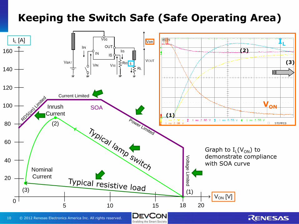
Keeping the Switch Safe (Safe Operating Area)
IL [A]
VON [V]
140
160
120
100
80
60
40
20
05 10 15 18 20
Inrush
Current
Nominal
Current
(3)
(2)
(1)
SOA
RDS(o
n) L
imite
dCurrent Limited
Power Limited
Vo
ltag
e L
imite
d
Graph to IL(VON) to demonstrate compliance with SOA curve
VON
IL
(1)
(2)
(3)

© 2012 Renesas Electronics America Inc. All rights reserved. 11
Terminal Short
Short close to the ECU* output connector
Immediate high current condition
Load Short
Short at the load but through the wiring harness
Immediate high current, but reduced by the wire harness resistance and inductance
Intermittent Short
Caused by moisture or wire pinch
Often high impedance and low current
Open Load
Can occur when power is on or off
Short to Battery
Can be caused by connector reversal or human error at vehicle assembly
Diagnosing Fault Conditions
* ECU = Electronic Control Unit
© 2012 Renesas Electronics America Inc. All rights reserved. 12
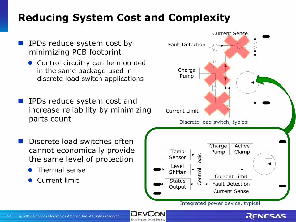
IPDs reduce system cost by minimizing PCB footprint
Control circuitry can be mounted in the same package used in discrete load switch applications
IPDs reduce system cost and increase reliability by minimizing parts count
Discrete load switches often cannot economically provide the same level of protection
Thermal sense
Current limit
Reducing System Cost and Complexity
Integrated power device, typical
ActiveClamp
Level Shifter
Fault Detection
Current Limit
Contr
ol Logic
Status Output
Temp Sensor
Current Sense
Charge Pump
Charge Pump
Current Sense
Current Limit
Fault Detection
Discrete load switch, typical

© 2012 Renesas Electronics America Inc. All rights reserved. 13
Key Performance Criteria for Automotive IPDs

© 2012 Renesas Electronics America Inc. All rights reserved. 14
Short Circuit Protection
VON
IL
(1)
(2)
(3)
A normal inrush current must not trigger current limit. In this case, the current limit, IL(SC), is
dependent upon the output saturation voltage, VON
IL [A]
VON [V]
140
160
120
100
80
60
40
20
05 10 15 18 20
IL(SC)
VON(OvL)
Inrush
Current
Nominal
Current(3)
(2)
(1)

© 2012 Renesas Electronics America Inc. All rights reserved. 15
Vds
Ids
Rds(on) characteristic
OC detection threshold
Over current detection and latch
・Shutdown immediately by over-current detection
・Over-current detection threshold accounts for lamp in-rush current
Hard short
”Grade A” (No failure、>1M cycles)
Load line
Soft short
Absolute Tch Method
ΔTch Method
175℃
60℃
Temperature
time
ΔTch1 protection for Power Limitation
・ΔTch detection with 2 temperature sensors to inhibit large temperature differential on die
Power MOSFET
Hot sensor
Cold sensor
Hot sensorCold sensor
:Power MOSFETの接合温度をモニター:ケース温度をモニター
Logic
+
-+
-Ref:60℃
Hysteretic interval:10℃
+
-Ref:175℃
1 Tch represents the channel (i.e. junction) temperature
Short-circuit Protection: Power Limitation
© 2012 Renesas Electronics America Inc. All rights reserved. 16
Manufacturers typically use load current to diagnose proper operation and to confirm an open load fault
Current sensing typically involves using an op amp to provide a ratio of the output current to the host MCU via an A/D input
Op amp input offset voltage and temperature drift limit the accuracy at low current values
Low current values lead to low output voltage at the op amp
Op amp offset and drift errors result in large errors for low current values, sometimes more than 30 to 40%
This large error is normally tolerable for lamps, but not LEDs
LEDs are becoming more prevalent
Customers demand outputs that are useful in both lamp and LED-configured vehicles
Current sense must be much more accurate at low currents to diagnose LED output currents
10% or better is requested
Current Sense Accuracy
* Commonly discussed in industry as “KILIS”, the gain from the sense current to the output load current

© 2012 Renesas Electronics America Inc. All rights reserved. 17
Key-off leakage current refers to the current drawn by a device even when it is off
Critical parameter for devices with a connection to the battery
Each ECU represents a valve for energy consumption from the battery, much like a faucet valve on a water supply
Goal is to maintain the battery charge when the vehicle is off
Typical body computer alone may have 10 or more IPDs in addition to other devices with connection to the battery!
Consider that there are vehicles today that are approaching 40+ ECUs in a vehicle, many of which are connected to the battery
Off-state leakage currents must be minimized!
Key-off Leakage Current
© 2012 Renesas Electronics America Inc. All rights reserved. 18
Many ECUs in a 12 V automotive application must continue to operate across a wide voltage range
One of the most extreme voltage conditions occurs when the engine is cranking
In cold temperatures, the voltage can drop as low as 4 V* momentarily until the back emf of the starter motor builds and the engine begins to crank
Critical outputs cannot be disabled during these conditions
– Fuel pump relay, headlights and more
IPD outputs generally are disabled as the voltage falls below the minimum guaranteed operating voltage
Protects the output from potential high linear power dissipation
Low Battery Operation
* Exact voltage values vary somewhat across the industry, but are generally lower than 6 V

© 2012 Renesas Electronics America Inc. All rights reserved. 19
Voltage transients are plentiful in the automotive environment!
High voltages could irreparably damage the output
One method to protect the device is to use active clamping output over-voltage shutdown
Active clamp allows the device to protect its internal logic
Active clamp activation allows the device to disable the output to protect the load from excessive output voltage
Many customers will dictate the required behavior for the IPD once the over-voltage condition is cleared
Some functions require that the output automatically recover
Others require that the output be latched off until the MCU can intervene to re-enable the output safely
Over-voltage Shutdown and Recovery

© 2012 Renesas Electronics America Inc. All rights reserved. 20
Open-load detection is typically required for reporting faults in lighting applications
Open-load detection can be performed by reading the output voltage
When there is a small current through and large voltage across the output, then the load is open (or the output could be shorted to the reference)
Open-load detection is normally signaled through a discrete fault pin to the MCU
In small-package, pin-limited IPD applications, the MCU may use a combination of current sense and discrete open-load detection to completely diagnose an open-load condition
Open Load Detection
© 2012 Renesas Electronics America Inc. All rights reserved. 21
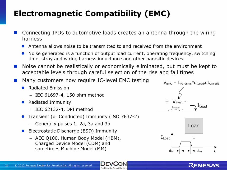
Connecting IPDs to automotive loads creates an antenna through the wiring harness
Antenna allows noise to be transmitted to and received from the environment
Noise generated is a function of output load current, operating frequency, switching time, stray and wiring harness inductance and other parasitic devices
Noise cannot be realistically or economically eliminated, but must be kept to acceptable levels through careful selection of the rise and fall times
Many customers now require IC-level EMC testing
Radiated Emission
– IEC 61697-4, 150 ohm method
Radiated Immunity
– IEC 62132-4, DPI method
Transient (or Conducted) Immunity (ISO 7637-2)
– Generally pulses 1, 2a, 3a and 3b
Electrostatic Discharge (ESD) Immunity
– AEC Q100, Human Body Model (HBM), Charged Device Model (CDM) and sometimes Machine Model (MM)
Electromagnetic Compatibility (EMC)
LParasitic
+ VEMC -
Load
ILoad
t
ILoad
dton dtoff
VEMC = LParasitic*dILoad/dtON(off)
© 2012 Renesas Electronics America Inc. All rights reserved. 22
Renesas Intelligent Power Devices (IPD)

© 2012 Renesas Electronics America Inc. All rights reserved. 23
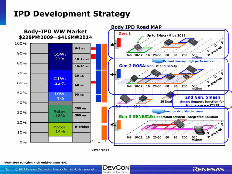
IPD Development Strategy
10%
25%
13%
45%
0%
10%
20%
30%
40%
50%
60%
70%
80%
90%
100%
1
IPD Worldwide Market $650M@2009 => $933M@2014
Body
Transmission
Engine
Brake
*FRM-IPD: Function Rich Multi-channel-IPD
Body-IPD WW Market $228M@2009→$416M@2014
Motor,
14%
Relay,
18%
10W,
9%
21W,
22%
55W,
27%
0%
10%
20%
30%
40%
50%
60%
70%
80%
90%
100%
1
6-8 mΩ
H-bridge
10-12 mΩ
16-20 mΩ
30 mΩ
60 mΩ
90 mΩ
200 mΩ
500 mΩ
© 2012 Renesas Electronics America Inc. All rights reserved. 24
IPD Development Strategy
Cover range
*FRM-IPD: Function Rich Multi-channel-IPD
6-8 10-12 16 20-30 60 90 200 500
S
D Q
6-8 10-12 16 20-30 60 90 200 500
S
D Q
12 Single 2 Single
Gen 1
Gen 2 ROSA: Robust and Safety
2nd Gen. Smash Smart Support function for
High accuracy KILIS
Gen 3 GENESIS: Generation System Integrated Solution
25 Dual
mOhm
mOhm
6-8 10-12 16 20-30 60 90 200 500
S
D Q
mOhm
Up to 5Mpcs/M by 2012
Expand Line-up, High performance
Function rich, Multi-channel
Body IPD Road MAP Body-IPD WW Market
$228M@2009→$416M@2014
Motor,
14%
Relay,
18%
10W,
9%
21W,
22%
55W,
27%
0%
10%
20%
30%
40%
50%
60%
70%
80%
90%
100%
1
6-8 mΩ
H-bridge
10-12 mΩ
16-20 mΩ
30 mΩ
60 mΩ
90 mΩ
200 mΩ
500 mΩ

© 2012 Renesas Electronics America Inc. All rights reserved. 25
Gen 1.0 IPDs for Incandescent Lighting
Load Ron Device Package
21W/
27W 60mOhm
12/24pin
PSOP for dual/quad
Flasher 25mOhm
55W/
65W
10 – 13 mOhm TO252
5 pin for single
65W/
75W 6mOhm
Single Dual Quad
uPD166017
uPD166010 uPD166009 uPD166007
uPD166011
uPD166013 uPD166014
MP Sample Design Planning
uPD166019 P-ch uPD166020 uPD166021
© 2012 Renesas Electronics America Inc. All rights reserved. 26
ROSA (i.e. Gen 2.0) Family Roadmap
Note: Ron values are typical values at 25°C
HEADLIGHT(55W, 65W, 75W)
HORN
NHS016B16mΩ
NHS012A12mΩ
NHS008A8mΩ
NHS010A10mΩ
NHS025B20mΩ
NHS012B12mΩ
NHD016C16mΩ
NHD030B30mΩ
NHD025B20mΩ
NHD012C12mΩ
ROSA IPD PRODUCT LINEUP
NHS006A6mΩ
NHS090B90mΩ
NHS050B50mΩ
NHD090B90mΩ
NHD050B50mΩ
NHQ090C90mΩ
NHQ050C50mΩ
TO-252-7
HSSOP-24
SINGLE
CHANNEL
QUAD
CHANNEL
DUAL CHANNEL
FLASHER, TAIL LAMP, STOP LAMP(10W, 20W, 30W)
HEATED SEAT
SIGNAL LAMP(5W, 10W)
LED
TARGET APPLICATION
MO272-12
MO226-12
Under development
© 2012 Renesas Electronics America Inc. All rights reserved. 27
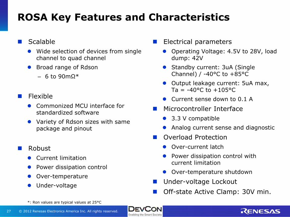
Scalable
Wide selection of devices from single channel to quad channel
Broad range of Rdson
– 6 to 90mΩ*
Flexible
Commonized MCU interface for standardized software
Variety of Rdson sizes with same package and pinout
Robust
Current limitation
Power dissipation control
Over-temperature
Under-voltage
Electrical parameters
Operating Voltage: 4.5V to 28V, load dump: 42V
Standby current: 3uA (Single Channel) / -40°C to +85°C
Output leakage current: 5uA max, Ta = -40°C to +105°C
Current sense down to 0.1 A
Microcontroller Interface
3.3 V compatible
Analog current sense and diagnostic
Overload Protection
Over-current latch
Power dissipation control with current limitation
Over-temperature shutdown
Under-voltage Lockout
Off-state Active Clamp: 30V min.
ROSA Key Features and Characteristics
*: Ron values are typical values at 25°C

© 2012 Renesas Electronics America Inc. All rights reserved. 28
World-class Current Sense Performance with SMASH1 Family Extension
Same operating and protection features as ROSA
Improve KILIS2 using “offset cancellation”
Allow measurement of current sense offset at any time to improve accuracy of current sense measurement
Target spec: +/- 5% accuracy over full load current range
Smaller packages: Jedec MO-153 (TSSOP)
Exposed pad type
Body size
– 14 pins: 4.4 mm x 5 mm
– 28 pins :4.4 mm x 7.8 mm
Pin pitch: 0.65 mm
2 Industry standard term for current sense gain, pronounced “key-less”
1 Smart Support function for High accuracy KILIS

© 2012 Renesas Electronics America Inc. All rights reserved. 29
Power MOS
Sense MOS
VBB
OUT
IS
Von
Voffset
IIS
IL
Circuit image
Calibration Current sense
IL
IIS
After calibration
Before calibration
Calibration
Calibration image
Op amp is main cause of KILIS tolerance and temperature drift
Additional mode routes the offset voltage of internal op amp to the current sense output
MCU reads offset value and stores it as a calibration value
MCU calculates “pure KILIS” by subtracting calibration value from current sense value
Re-calibration can be performed as needed during BCM operation
Smart Support Function for Accurate KILIS
IN
SEN
IL
IIS
KILIS
Calibration
IIS,offset level
Start Calibration
End Calibration
Pure KILIS

© 2012 Renesas Electronics America Inc. All rights reserved. 30
Evaluation Development Support Tools
Customer evaluation boards are available for both the 12-pin and 24-pin HSSOP devices
Independent source and sense pins for accurate measurements
Prototype area for mounting external components according to the evaluation needs
Solder Mount Version Socket Mount Version
Reflow
Sid
e
Wave S
ide
© 2012 Renesas Electronics America Inc. All rights reserved. 31
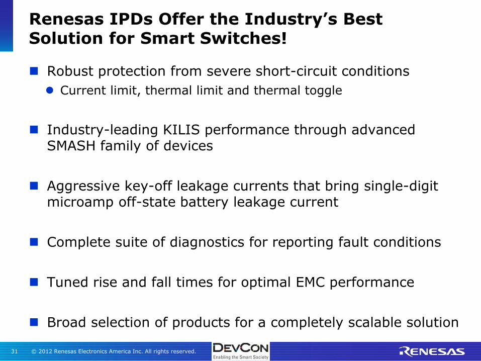
Renesas IPDs Offer the Industry’s Best Solution for Smart Switches!
Robust protection from severe short-circuit conditions
Current limit, thermal limit and thermal toggle
Industry-leading KILIS performance through advanced SMASH family of devices
Aggressive key-off leakage currents that bring single-digit microamp off-state battery leakage current
Complete suite of diagnostics for reporting fault conditions
Tuned rise and fall times for optimal EMC performance
Broad selection of products for a completely scalable solution

© 2012 Renesas Electronics America Inc. All rights reserved. 32
Questions?
© 2012 Renesas Electronics America Inc. All rights reserved. 33
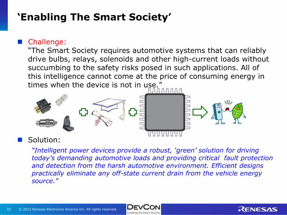
‘Enabling The Smart Society’
Challenge: “The Smart Society requires automotive systems that can reliably drive bulbs, relays, solenoids and other high-current loads without succumbing to the safety risks posed in such applications. All of this intelligence cannot come at the price of consuming energy in times when the device is not in use.”
Solution:
“Intelligent power devices provide a robust, ‘green’ solution for driving today’s demanding automotive loads and providing critical fault protection and detection from the harsh automotive environment. Efficient designs practically eliminate any off-state current drain from the vehicle energy source.”

© 2012 Renesas Electronics America Inc. All rights reserved. 34
Please utilize the ‘Guidebook’ application to leave feedback
or
Ask me for the paper feedback form for you to use…
Please Provide Your Feedback…

Renesas Electronics America Inc.
© 2012 Renesas Electronics America Inc. All rights reserved.