InteliCompact NT 2.0 Reference Guide
288
Reference Guide Pa rall eli ng gen-set co ntroller SW version 2.0, April 2014 Copyright ©2014 ComAp a.s. ComAp a.s. Kundratka 17, 180 00 Praha 8, Czech Republic Tel: +420 246 012 111, Fax: +420 266 316 647 E-mail:[email protected], www.comap.cz
-
Upload
julio-hinostroza-alarcon -
Category
Documents
-
view
282 -
download
29
Transcript of InteliCompact NT 2.0 Reference Guide

8/15/2019 InteliCompact NT 2.0 Reference Guide
http://slidepdf.com/reader/full/intelicompact-nt-20-reference-guide 1/287
Reference Guide
Paral le l ing gen-set co ntrol ler
SW version 2.0, April 2014
Copyright ©2014 ComAp a.s.
ComAp a.s. Kundratka 17, 180 00 Praha 8, Czech RepublicTel: +420 246 012 111, Fax: +420 266 316 647
E-mail:[email protected], www.comap.cz

8/15/2019 InteliCompact NT 2.0 Reference Guide
http://slidepdf.com/reader/full/intelicompact-nt-20-reference-guide 2/287
InteliCompactNT
, SW version 2.0InteliCompact-NT-2.0-Reference Guide.pdf, ©ComAp – April 2014 2
Table of contents
1 Document information ................................................................................................................... 7
1.1 Clarification of notation ............................................................................................................... 8
1.2 Conformity Declaration ............................................................................................................... 8
2 System overview ............................................................................................................................ 9
2.1 General description .................................................................................................................... 9
2.2 Configurability and monitoring .................................................................................................... 9
2.2.1 LiteEdit ............................................................................................................................. 10
2.2.2 InteliMonitor ..................................................................................................................... 11
2.2.3 WinScope ......................................................................................................................... 11
2.2.4 WebSupervisor ................................................................................................................ 11
2.3 Applications overview ............................................................................................................... 12
2.3.1 Single applications ........................................................................................................... 12
2.3.2 Multiple applications ........................................................................................................ 12
2.4 True RMS measurement .......................................................................................................... 13
3 Installation .................................................................................................................................... 14
3.1 Mounting ................................................................................................................................... 14
3.2 Package contents ..................................................................................................................... 14
3.3 Dimensions ............................................................................................................................... 15
3.4 Terminal diagram ...................................................................................................................... 16
3.5 General ..................................................................................................................................... 16
3.6 Wiring........................................................................................................................................ 17
3.7 Grounding ................................................................................................................................. 17
3.8 Power supply ............................................................................................................................ 17
3.8.1 Power supply fusing ......................................................................................................... 19
3.9 Voltage and current inputs ....................................................................................................... 19
3.10 Speed measurement ................................................................................................................ 21
3.10.1 Pickup .............................................................................................................................. 21
3.10.2 Generator frequency ........................................................................................................ 22
3.10.3 Additional running engine indication ................................................................................ 22
3.11 Binary inputs ............................................................................................................................. 23
3.12 Binary outputs ........................................................................................................................... 23
3.13 Analog inputs ............................................................................................................................ 24
3.13.1 Tristate inputs .................................................................................................................. 25
3.14 Circuit breakers ........................................................................................................................ 26
3.14.1 Breaker control outputs .................................................................................................... 26
3.14.2 MCB special requirements ............................................................................................... 27
3.15 AVR interface ........................................................................................................................... 27
3.15.1 IG-AVRi ............................................................................................................................ 27
3.15.2 AVR list ............................................................................................................................ 30
3.16 Speed governor interface ......................................................................................................... 42
3.16.1 Speed governor list .......................................................................................................... 43
3.17 CAN bus wiring ......................................................................................................................... 50
3.18 Recommended CAN/RS485 connection .................................................................................. 51
3.18.1 CAN bus connection ........................................................................................................ 51
3.18.2 RS485 connection ........................................................................................................... 51
3.19 Extension modules ................................................................................................................... 53
3.19.1 IGS-PTM .......................................................................................................................... 53
3.19.2 IGL-RA15 remote annunciator ......................................................................................... 54
3.19.3 IL-NT-AOUT8 ................................................................................................................... 55
3.19.4 IL-NT BIO8 ....................................................................................................................... 55
3.19.5 IC-NT CT-BIO7 ................................................................................................................ 57
3.20 Communication modules .......................................................................................................... 59
3.20.1
IL-NT RS232 .................................................................................................................... 59
3.20.2 IL-NT RS232-485 ............................................................................................................. 60
3.20.3 IL-NT S-USB .................................................................................................................... 60

8/15/2019 InteliCompact NT 2.0 Reference Guide
http://slidepdf.com/reader/full/intelicompact-nt-20-reference-guide 3/287
InteliCompactNT
, SW version 2.0InteliCompact-NT-2.0-Reference Guide.pdf, ©ComAp – April 2014 3
3.20.4 IB-Lite ............................................................................................................................... 61
3.20.5 IL-NT GPRS ..................................................................................................................... 62
3.20.6 InternetBridge-NT ............................................................................................................ 64
3.21 EFI engines .............................................................................................................................. 65
3.21.1 Differences between a classic and EFI-engine application ............................................. 65
3.22 Typical wiring – EFI engine ...................................................................................................... 68
3.23 Typical wiring – c lassic engine ................................................................................................. 69 3.24 Emergency Stop ....................................................................................................................... 71
4 Putting it into operation ............................................................................................................... 72
4.1 Programming the configuration ................................................................................................ 72
4.2 Programming the firmware ....................................................................................................... 72
4.3 Programming a non-responsive controller ............................................................................... 73
4.5 Factory default configuration .................................................................................................... 74
4.5.1 SPtM ................................................................................................................................ 74
4.5.2 MINT ................................................................................................................................ 75
4.6 Step-by-step guide ................................................................................................................... 76
5 Operator guide .............................................................................................................................. 78
5.1 Front panel elements ................................................................................................................ 78
5.2 User interface modes ............................................................................................................... 80 5.3 Display screens and pages structure ....................................................................................... 80
5.4 View measured values ............................................................................................................. 82
5.5 Setpoints – view and change ................................................................................................... 82
5.6 Browsing the history log ........................................................................................................... 83
5.7 Browsing alarms ....................................................................................................................... 84
5.8 Entering the password .............................................................................................................. 85
5.9 Controller information screen ................................................................................................... 85
5.10 Controller language selection ................................................................................................... 87
5.11 User interface mode selection .................................................................................................. 87
5.12 Display contrast adjustment ..................................................................................................... 87
6 Function description .................................................................................................................... 88
6.1 Island operation flowchart ........................................................................................................ 88
6.2 Parallel operation flowchart ...................................................................................................... 89
6.3 Operating modes ...................................................................................................................... 90
6.3.1 OFF .................................................................................................................................. 90
6.3.2 MAN ................................................................................................................................. 90
6.3.3 AUT .................................................................................................................................. 91
6.3.4 TEST ................................................................................................................................ 91
6.4 Engine start .............................................................................................................................. 92
6.4.1 Diesel engine ................................................................................................................... 92
6.4.2 Gas engine ....................................................................................................................... 94
6.5 Stabilization .............................................................................................................................. 96
6.6 Connecting to the load.............................................................................................................. 96
6.6.1 Connecting to dead bus ................................................................................................... 97
6.6.2
Synchronizing .................................................................................................................. 97
6.7 Parallel to mains operation –SPtM .......................................................................................... 98
6.7.1 Ramping the power up ..................................................................................................... 98
6.7.2 Load control ..................................................................................................................... 98
6.7.3 Power factor control ......................................................................................................... 98
6.7.4 Object load dependent auto start .................................................................................... 99
6.7.5 Ramping the power down ................................................................................................ 99
6.7.6 Peak load shaving ........................................................................................................... 99
6.7.7 Export Limit ...................................................................................................................... 99
6.8 Parallel to mains operation –MINT ........................................................................................ 102
6.8.1 Ramping the power up ................................................................................................... 102
6.8.2 Load control modes ....................................................................................................... 102
6.8.3 Power factor control ....................................................................................................... 102
6.8.4
Ramping the power down .............................................................................................. 102
6.9 Island operation –SPtM ......................................................................................................... 102
6.9.1 Island to PtM transfers ................................................................................................... 103

8/15/2019 InteliCompact NT 2.0 Reference Guide
http://slidepdf.com/reader/full/intelicompact-nt-20-reference-guide 4/287
InteliCompactNT
, SW version 2.0InteliCompact-NT-2.0-Reference Guide.pdf, ©ComAp – April 2014 4
6.10 Island operation –MINT ......................................................................................................... 103
6.11 Power management ............................................................................................................... 104
6.11.1 The concept ................................................................................................................... 104
6.11.2 Basics ............................................................................................................................ 104
6.11.3 Reserves, minimal running power ................................................................................. 105
6.11.4 Priorities ......................................................................................................................... 105
6.11.5 Load Demand Start/Stop ............................................................................................... 106 6.11.6 Reaction to alarms ......................................................................................................... 107
6.11.7 Related binary inputs ..................................................................................................... 107
6.11.8 Related binary outputs ................................................................................................... 108
6.11.9 Load Demand Swap ...................................................................................................... 108
6.11.10 Related binary inputs ..................................................................................................... 109
6.11.11 Related binary outputs ................................................................................................... 109
6.11.12 “How to” examples: ........................................................................................................ 109
6.11.13 Related setpoints and values ......................................................................................... 110
6.12 AMF function .......................................................................................................................... 110
6.12.1 Mains failure detection ................................................................................................... 110
6.12.2 Healthy mains detection ................................................................................................ 111
6.12.3 The AMF procedure ....................................................................................................... 111
6.13 Engine cool down and stop .................................................................................................... 111 6.13.1 Stopped gen-set evaluation ........................................................................................... 112
6.14 Alarm management ................................................................................................................ 112
6.14.1 Alarm handling ............................................................................................................... 113
6.14.2 Alarm states ................................................................................................................... 113
6.14.3 Alarm types –Yellow level ............................................................................................. 114
6.14.4 Alarm types –Red level ................................................................................................. 114
6.14.5 Sensor fail detection (FLS) ............................................................................................ 114
6.14.6 Remote alarm messaging .............................................................................................. 115
6.14.7 Alarmlist ......................................................................................................................... 116
6.14.8 ECU Alarmlist................................................................................................................. 116
6.14.9 Built-in alarms ................................................................................................................ 117
6.15 History log ............................................................................................................................... 117
6.16 Exercise timers ....................................................................................................................... 120 6.16.1 MINT .............................................................................................................................. 121
6.16.2 SPtM .............................................................................................................................. 121
6.17 Analog switches ...................................................................................................................... 121
6.18 Power switch .......................................................................................................................... 122
6.19 Regulation loops ..................................................................................................................... 122
6.19.1 SPtM .............................................................................................................................. 122
6.19.2 MINT .............................................................................................................................. 123
6.19.3 Regulation control loops overview ................................................................................. 124
6.19.4 PI regulation adjustment ................................................................................................ 124
7 Setpoints ..................................................................................................................................... 126
7.1 Password protection ............................................................................................................... 126
7.2 Setpoint synchronization ........................................................................................................ 126
7.3 Setpoint groups ...................................................................................................................... 126
7.3.1 Setpoints – Process Control .......................................................................................... 127
7.3.2 Setpoints –Basic Settings ............................................................................................. 127
7.3.3 Setpoints – Comms Settings ......................................................................................... 127
7.3.4 Setpoints – Engine Params ........................................................................................... 128
7.3.5 Setpoints – Engine Protect ............................................................................................ 128
7.3.6 Setpoints – Gener Protect ............................................................................................. 128
7.3.7 Setpoints –Pwr Management ........................................................................................ 129
7.3.8 Setpoints – AMF Settings .............................................................................................. 129
7.3.9 Setpoints – Sync/Load Ctrl ............................................................................................ 130
7.3.10 Setpoints – Volt/PF Control ........................................................................................... 130
7.3.11 Setpoints – ExtI/O Protect ............................................................................................. 130
7.3.12
Setpoints –SMS/E-Mail ................................................................................................. 130
7.3.13 Setpoints –AnalogSwitches .......................................................................................... 131
7.3.14 Setpoints –Date/Time ................................................................................................... 131

8/15/2019 InteliCompact NT 2.0 Reference Guide
http://slidepdf.com/reader/full/intelicompact-nt-20-reference-guide 5/287
InteliCompactNT
, SW version 2.0InteliCompact-NT-2.0-Reference Guide.pdf, ©ComAp – April 2014 5
7.3.15 Setpoints – Sensors Spec ............................................................................................. 131
8 Values .......................................................................................................................................... 132
8.1 Invalid flag .............................................................................................................................. 132
8.2 Value groups .......................................................................................................................... 132
8.2.1 Values – Engine ............................................................................................................. 132
8.2.2 Values –Generator ........................................................................................................ 133
8.2.3 Values –Mains .............................................................................................................. 133
8.2.4 Values – Bus .................................................................................................................. 134
8.2.5 Values –Pwr Management ............................................................................................ 134
8.2.6 Values – Controller I/O .................................................................................................. 134
8.2.7 Values –Extension I/O .................................................................................................. 134
8.2.8 Values –Statistics ......................................................................................................... 135
8.2.9 Values –Date/Time ....................................................................................................... 135
8.2.10 Values – Info .................................................................................................................. 135
9 Binary input functions ............................................................................................................... 136
9.1 Common functions .................................................................................................................. 136
9.2 MINT specific .......................................................................................................................... 136
9.3 SPtM specific .......................................................................................................................... 136
10 Binary output functions ....................................................................................................... 137
10.1 Common functions .................................................................................................................. 137
10.2 ECU info ................................................................................................................................. 137
10.3 Alarm mirrors .......................................................................................................................... 138
10.4 MINT specific .......................................................................................................................... 139
10.5 SPtM specific .......................................................................................................................... 139
11 Communication .................................................................................................................... 140
11.1 Direct cable connection .......................................................................................................... 140
11.2 Modem connection ................................................................................................................. 141
11.2.1 Recommended GSM modems ...................................................................................... 141
11.2.2 Modem setup procedure ................................................................................................ 142
11.3 Internet connection ................................................................................................................. 142
11.3.1 SPtM .............................................................................................................................. 142 11.3.2 MINT .............................................................................................................................. 143
11.3.3 Using a web browser ..................................................................................................... 144
11.3.4 IB-Lite setup procedure ................................................................................................. 144
11.3.5 System integration ......................................................................................................... 145
11.3.6 InternetBridge-NT setup procedure ............................................................................... 145
11.3.7 IG-IB setup procedure ................................................................................................... 145
11.3.8 SNMP ............................................................................................................................. 145
11.3.9 AirGate ........................................................................................................................... 145
11.3.10 Locate ............................................................................................................................ 145
11.4 Modbus protocol ..................................................................................................................... 146
11.5 IC-NT-RD Remote display software ....................................................................................... 147
12
Maintenance .......................................................................................................................... 148
12.1 Backup battery replacement ................................................................................................... 148
13 Troubleshooting ................................................................................................................... 150
14 Technical data ....................................................................................................................... 153
14.1 Power supply .......................................................................................................................... 153
14.2 Operating conditions ............................................................................................................... 153
14.3 Physical dimensions ............................................................................................................... 153
14.4 Standard conformity ............................................................................................................... 153
14.5 Binary inputs ........................................................................................................................... 154
14.6 Binary outputs ......................................................................................................................... 154
14.7 Analog inputs .......................................................................................................................... 154
14.8 Generator/Mains measurements ............................................................................................ 154
14.9
Pickup input ............................................................................................................................ 155
14.10 Charging alternator pre-excitation circuit ................................................................................ 155
14.11 AVR output ............................................................................................................................. 155

8/15/2019 InteliCompact NT 2.0 Reference Guide
http://slidepdf.com/reader/full/intelicompact-nt-20-reference-guide 6/287
InteliCompactNT
, SW version 2.0InteliCompact-NT-2.0-Reference Guide.pdf, ©ComAp – April 2014 6
14.11.1 IG-AVRi module ............................................................................................................. 155
14.11.2 IG-AVRi Trans/LV .......................................................................................................... 155
14.11.3 IG-AVRi Trans/100 ........................................................................................................ 156
14.12 Governor output ...................................................................................................................... 156
14.13 Remote communication interface ........................................................................................... 156
14.14 Extension modules interface .................................................................................................. 156
14.15 Interface to other controllers ................................................................................................... 156 14.15.1 Recommended CAN cables .......................................................................................... 157
15 Language support ................................................................................................................ 158
16 Appendix ............................................................................................................................... 159
16.1 Table of setpoints ................................................................................................................... 159
16.1.1 Group: Process Control ................................................................................................. 159
16.1.2 Group: Basic Settings .................................................................................................... 163
16.1.3 Group: Comms Settings ................................................................................................ 167
16.1.4 Group: Engine Params .................................................................................................. 173
16.1.5 Group: Engine Protect ................................................................................................... 178
16.1.6 Group: Gener Protect .................................................................................................... 182
16.1.7 Group: Pwr Management ............................................................................................... 187
16.1.8 Group: AMF Settings ..................................................................................................... 194 16.1.9 Group: Sync/Load Ctrl ................................................................................................... 198
16.1.10 Group: Volt/PF Ctrl ........................................................................................................ 203
16.1.11 Group: ExtI/O Protect .................................................................................................... 204
16.1.12 Group: SMS/E-Mail ........................................................................................................ 207
16.1.13 Group: AnalogSwitches ................................................................................................. 208
16.1.14 Group: Date/Time .......................................................................................................... 210
16.1.15 Group: Sensors Spec .................................................................................................... 214
16.2 Table of values ....................................................................................................................... 217
16.2.1 Group: Engine ................................................................................................................ 217
16.2.2 Group: Generator ........................................................................................................... 220
16.2.3 Group: Mains ................................................................................................................. 226
16.2.4 Group: Bus ..................................................................................................................... 230
16.2.5 Group: Pwr Management ............................................................................................... 232 16.2.6 Group: Controller I/O ..................................................................................................... 234
16.2.7 Group: Extension I/O ..................................................................................................... 238
16.2.8 Group: Statistics............................................................................................................. 240
16.2.9 Group: Date/Time .......................................................................................................... 242
16.2.10 Group: Info ..................................................................................................................... 243
16.3 Table of binary input functions ............................................................................................... 245
16.3.1 Common functions ......................................................................................................... 245
16.3.2 MINT specific ................................................................................................................. 249
16.3.3 SPtM specific ................................................................................................................. 250
16.4 Table of binary output functions ............................................................................................. 251
16.4.1 Common functions ......................................................................................................... 251
16.4.2 ECU info ......................................................................................................................... 259
16.4.3 Alarm mirrors ................................................................................................................. 261 16.4.4 MINT specific ................................................................................................................. 271
16.4.5 SPtM specific ................................................................................................................. 272
16.5 Table of internal alarms .......................................................................................................... 273

8/15/2019 InteliCompact NT 2.0 Reference Guide
http://slidepdf.com/reader/full/intelicompact-nt-20-reference-guide 7/287
InteliCompactNT
, SW version 2.0InteliCompact-NT-2.0-Reference Guide.pdf, ©ComAp – April 2014 7
1 Document information
InteliCompact-NT® – Reference guide
Written by: Jan Tomandl, Revised by: Jan Donat, Jan Podlipny©2013 ComAp a.s.Kundratka 17, Praha 8, Czech RepublicPhone: +420246012111, fax: +420266316647Web: HTTP://WWW.COMAP.CZ, e-mail: [email protected]
DOCUMENT HISTORY
REVISION NUMBER RELATED SW. VERSION DATE
1 1.0 30.05.2008
2 1.1 25.03.2009
3 1.2 22.10.2009
4 1.2.2 11.05.2010
5 1.3.1 28.11.2011
6 1.4 06.03.2013
7 2.0 30.04.2014
This documentation is also available in electronic form as a Windows help fileInteliCompact-NT.chm. The help can be opened from Windows Explorer or directly fromthe LiteEdit menu bar (if a connection is established to an InteliCompact
NTcontroller).
Pressing F1 in the LiteEdit setpoint, values or configuration window will open the helpwith the context of currently selected setpoint, value and binary input or output function.

8/15/2019 InteliCompact NT 2.0 Reference Guide
http://slidepdf.com/reader/full/intelicompact-nt-20-reference-guide 8/287

8/15/2019 InteliCompact NT 2.0 Reference Guide
http://slidepdf.com/reader/full/intelicompact-nt-20-reference-guide 9/287
InteliCompactNT
, SW version 2.0InteliCompact-NT-2.0-Reference Guide.pdf, ©ComAp – April 2014 9
2 System overview
2.1 General descrip t ion
InteliCompactNT
(also IC-NT) Family controllers are comprehensive gen-set controllers for single andmultiple generating sets operating in stand-by or parallel modes. A modular construction allowsupgrades to different levels of complexity in order to provide the best solution for various customerapplications. The controllers are equipped with a powerful graphic display showing icons, symbols andbar graphs for intuitive operation, which, together with its high level of functionality, sets newstandards in Gen-set controls.
The key features are:
Easy-to-use operation and installation. The factory default configuration covers mostapplications
Various customizations are possible thanks to its configurability
Excellent remote communication capabilities
High level of support for EFI engines (most world producers)
High reliability
2.2 Conf igurabi l ity and monitor ing
One of the key features of the controller is the system’s high level of adaptability to the needs of eachindividual application and wide possibilities for monitoring. This can be achieved by configuring andusing the powerful ComAp PC/mobile tools.
Supported configuration and monitoring tools:
- LiteEdit – complete configuration and single gen-set monitoring- InteliMonitor – multiple site monitoring and setpoint setting- WinScope – special graphical monitoring software- WebSupervisor – web-based system for monitoring and controlling
o WebSupervisor mobile – supporting application for smartphones
NOTE: Use the LiteEdit PC software to read, view and modify configuration from the controller or disk andwrite the new configuration to the controller or disk.
The firmware of InteliCompactNT
contains a large number of binary inputs and outputs needed for allnecessary functions available. However, not all functions are required at the same time on the samegen-set and also the controller hardware does not have so many input and output terminals. One ofthe main tasks of the configuration is mapping of “logical” firmware inputs and outputs to the “physical”hardware inputs and outputs.
Configuration parts:
1. Mapping of logical binary inputs (functions) or assigning alarms to physical binary inputterminals
2. Mapping of logical binary outputs (functions) to physical binary output terminals3. Assigning sensor characteristics and alarms to analog inputs4. Assigning control values and output characteristics to analog outputs5. Selection of peripheral modules which are connected to the controller and doing the same as
the above for them
6. Selection of ECU type if an ECU is connected7. Changing the language of the controller interface

8/15/2019 InteliCompact NT 2.0 Reference Guide
http://slidepdf.com/reader/full/intelicompact-nt-20-reference-guide 10/287
InteliCompactNT
, SW version 2.0InteliCompact-NT-2.0-Reference Guide.pdf, ©ComAp – April 2014 10
CONFIGURATION OF
BINARY INPUTS AND
OUTPUTS
“Logical” inputs
“Logical” outputs
Main program (control loop)
Alarm
management
FIRMWARE
CONTROLLER
Physical input terminals
Physical output terminals
PRINCIPLE OF BINARY INPUTS AND OUTPUTS CONFIGURATION
The controller is shipped with a default configuration, which should be suitable for most standardapplications. This default configuration can be changed only by using a PC with the LiteEdit software.See LiteEdit documentation for details.
NOTE: You need one of communication modules to connect the controller to a PC with LiteEdit. There is aspecial easy removable service module for cases when no communication module is permanentlyattached.
Once the configuration is modified, it can be saved to a file for later usage with another controller or forbackup purposes. The file is called archive and has the file extension .aic. An archive contains a fullimage of the controller at the time of saving (if the controller is online for the PC) except the firmware.Besides configuration it also contains current adjustment of all setpoints, all measured values, a copyof the history log and a copy of the alarm list.
The archive can be simply used for cloning controllers, i.e. preparing controllers with identicalconfiguration and settings.
2.2.1 LiteEdit
Configuration and monitoring tool for InteliCompactNT
, InteliLiteNT
and other controllers. See more inLiteEdit Reference Guide.
This tool provides the following functions:- Direct, modem or internet communication with
the controller- Offline or online controller configuration- Controller firmware upgrade- Reading/writing/adjustment of setpoints- Reading of measured values- Browsing of controller history records- Exporting data into a XLS file
- Controller language translation

8/15/2019 InteliCompact NT 2.0 Reference Guide
http://slidepdf.com/reader/full/intelicompact-nt-20-reference-guide 11/287

8/15/2019 InteliCompact NT 2.0 Reference Guide
http://slidepdf.com/reader/full/intelicompact-nt-20-reference-guide 12/287
InteliCompactNT
, SW version 2.0InteliCompact-NT-2.0-Reference Guide.pdf, ©ComAp – April 2014 12
2.3 Applicat ion s overview
2.3.1 Single applications
The typical scheme of a single parallel to mains application is shown below. The controller controls
two breakers – a mains breaker and a generator breaker. Feedback from both breakers is required.
MCB
3x
K4
MCB
MCB CLOSE/OPEN
GCB3x
K3
GCB
GCB CLOSE/OPEN
G1
3 P h U M 3
P h U G
3x
InteliCompactNT
SPtMBO
BI
3 P h I G
IG-AVRi
SG+
AVRi
SPEED GOVERNOR
CAN1
AVR
ECUMCB
GCB
MCB FEEDBACK
GCB FEEDBACK
ECU
SINGLE PARALLEL TO MAINS APPLICATION
2.3.2 Multiple applications
The typical schemes are multiple island-parallel application without mains and multiple parallelapplication with mains. Both are shown below. The controller controls one breaker only, the generatorbreaker. Feedback from the generator breaker is required. For parallel to mains operation also mainsbreaker feedback is required.
GCB3x
K3
GCB
GCB CLOSE/OPEN
G1
3 P h U B 3
P h U G
3x
InteliCompactNT
MINTBO
BI
3 P h I G
IG-AVRi
SG+
AVRi
SPEED GOVERNOR
GCB
K3
GCB
GCB CLOSE/OPEN
G2
3 P h U B 3
P h U G
3x
InteliCompactNT
MINTBO
BI
3 P h I G
IG-AVRi
SG+
AVRi
SPEED GOVERNOR
SYS START/STOP
SYS START/STOP
START/STOP
CAN2
CAN2
AVR
AVR
CAN
CAN
CAN1
CAN1
ECU
ECU
ECU
ECU
GCBGCB FEEDBACK
GCBGCB FEEDBACK
ISLAND-PARALLEL OPERATION WITHOUT MAINS

8/15/2019 InteliCompact NT 2.0 Reference Guide
http://slidepdf.com/reader/full/intelicompact-nt-20-reference-guide 13/287
InteliCompactNT
, SW version 2.0InteliCompact-NT-2.0-Reference Guide.pdf, ©ComAp – April 2014 13
GCB3x
K3
GCB
GCB CLOSE/OPEN
G1
3 P h U
B 3 P h U G
3x
InteliCompactNT
MINTBO
BI
3 P h I G
IG-AVRi
SG+
AVRi
SPEED GOVERNOR
GCB
K3
GCB
GCB CLOSE/OPEN
G2
3 P h U B 3
P h U G
3x
InteliCompactNT
MINTBO
BI
3 P h I G
IG-AVRi
SG+
AVRi
SPEED GOVERNOR
SYS START/STOP
SYS START/STOP
S Y S S T A R T / S T O P
CAN2
CAN2
AVR
AVR
CAN
CAN
CAN1
CAN1
ECU
ECU
ECU
ECU
MCB
3x
K4
MCB
MainsCompactNT
BO
BI CAN
MCBMCB FEEDBACK
3 P h I M
3 P h U M
3Ph UB
MCB CLOSE/OPEN
REM START/STOP
MCB FEEDBACK
MCB FEEDBACK
M C B F D B M I R R O R
GCBGCB FEEDBACK
GCBGCB FEEDBACK
ISLAND-PARALLEL OPERATION WITH AMF AND WITHOUT PARALLELING
2.4 True RMS measurement
This controller measures AC values based on the True RMS principle. This principle corresponds
exactly to the physical definition of alternating voltage and current effective values. Under normalcircumstances the mains voltage and current should have a pure sinusoidal waveform. However,some nonlinear elements connected to the mains produce harmonic waveforms with frequencies ofmultiples of the basic mains frequency and this may result in deformation of the voltage and/or currentwaveforms. The True RMS measurement gives accurate readings of effective values not only forpure sinusoidal waveforms, but also for deformed waveforms.
NOTE: The harmonic deformation causes that the Power Factor of a generator working parallel with themains cannot reach values in a certain range around the PF 1.00. The higher the deformation, thewider the power factor dead range. If the requested power factor is adjusted inside the dead range,the controller cannot reach the requested value because of this fact.

8/15/2019 InteliCompact NT 2.0 Reference Guide
http://slidepdf.com/reader/full/intelicompact-nt-20-reference-guide 14/287
InteliCompactNT
, SW version 2.0InteliCompact-NT-2.0-Reference Guide.pdf, ©ComAp – April 2014 14
3 Installation
3.1 Mount ing
The controller is to be mounted onto the switchboard door. The requested cut-out size is 175x115 mm.Use the screw holders delivered with the controller to fix the controller into the door as described in thepictures below.
3.2 Package conten ts
The package contains:
Controller
Mounting holders
Terminal blocks
NOTE: The package does not contain a communication module. The required module should be ordered
separately.

8/15/2019 InteliCompact NT 2.0 Reference Guide
http://slidepdf.com/reader/full/intelicompact-nt-20-reference-guide 15/287
InteliCompactNT
, SW version 2.0InteliCompact-NT-2.0-Reference Guide.pdf, ©ComAp – April 2014 15
3.3 Dimensions
29
58
47
185
1 2 5
1 1 0
8 0
168
D ++ -
NT
InteliCompact
Mounting cutout size: 175 x 115 mm
NOTE: The dimensions are in millimetres and are the same for both versions – SPTM and MINT.

8/15/2019 InteliCompact NT 2.0 Reference Guide
http://slidepdf.com/reader/full/intelicompact-nt-20-reference-guide 16/287
InteliCompactNT
, SW version 2.0InteliCompact-NT-2.0-Reference Guide.pdf, ©ComAp – April 2014 16
3.4 Termin al diagr am
MINT
SPTM
3.5 General
To ensure proper function:
Use grounding terminals.
Wiring for binary inputs and analog inputs must not be run with power cables.
Analog and binary inputs should use shielded cables, especially when the length is more than3 m.

8/15/2019 InteliCompact NT 2.0 Reference Guide
http://slidepdf.com/reader/full/intelicompact-nt-20-reference-guide 17/287
InteliCompactNT
, SW version 2.0InteliCompact-NT-2.0-Reference Guide.pdf, ©ComAp – April 2014 17
3.6 Wiring
Tightening torque, allowed wire size and type, for the Field-Wiring Terminals:
Based on terminal type:1. PA256:
SPECIFIED TIGHTENING TORQUE 0.5 NM (4.4 IN-LB)
2. 2EDGK:
SPECIFIED TIGHTENING TORQUE 0.4 NM (3.5 IN-LB)
For field type terminals:Use only diameter 2.0 –0.5 mm (12 –26 AWG) conductor, rated for 75 °C minimum.
For Mains (Bus) Voltage and Generator Voltage terminalsUse only diameter 2.0-0.5 mm (12 –26 AWG) conductor, rated for 90 °C minimum.
Use copper conductors only.
3.7 Grounding
The shortest possible piece of wire should be used for controller grounding. Use cable min. 2.5 mm2.
A brass M4x10 screw with star washer securing ring type grounding terminal shall be used.
The negative “-” battery terminal must be properly grounded.
Switchboard and engine must be grounded at a common point. Use as short a cable aspossible to the grounding point.
3.8 Power sup ply
To ensure proper function:Use min. power supply cable of 1.5 mm
2
The maximum continuous DC power supply voltage is 36 V DC. The maximum allowable powersupply voltage is 39 V DC. The InteliCompact’s power supply terminals are protected against largepulse power disturbances. When there is a potential risk of the controller being subjected toconditions outside its capabilities, an outside protection device should be used.
It is necessary to ensure that potential difference between the generator current COM terminaland the battery “-” terminal is maximum ± 2 V. Therefore, it is strongly recommended tointerconnect these two terminals together.
H INT :
The InteliCompactNT
controller should be grounded properly in order to protect against lighting strikes!!
The maximum allowable current through the controller’s negative terminal is 4A (this is dependent onbinary output load).

8/15/2019 InteliCompact NT 2.0 Reference Guide
http://slidepdf.com/reader/full/intelicompact-nt-20-reference-guide 18/287
InteliCompactNT
, SW version 2.0InteliCompact-NT-2.0-Reference Guide.pdf, ©ComAp – April 2014 18
For connection with a 12 V DC power supply, the InteliCompactNT
includes internal capacitors thatallow the controller to continue operation during cranking if the battery voltage dip occurs. If the batteryvoltage is 10 V before the dip and it recovers to 7 V within 100 ms the controller continues operating.During this voltage dip, the controller screen backlight may turn on and off but the controller keepsoperating.
It is possible to further support the controller by connecting the external capacitor and separating
diode or I-LBA module:
+-
T1A
+ -
+
-
D
C
+
Relays
Controller
Starter
Battery12 VDC
The capacitor size depends on the required time. It shall be approximately in the thousands ofmicrofarads.
The capacitor size should be 5000 microfarad to withstand a 150 ms voltage dip under the followingconditions:
Voltage before dip is 12 V, after 150 ms the voltage recovers to the min. allowed voltage, i.e. 8 V.
H INT :
Before the battery is discharged the message "Low BackupBatt" appears.
Or by connecting a special I-LBA Low Battery Adaptor module:
+-
T1A
+ -
+
-
Relays
Controller
Starter
Battery12 VDC
I - L B A
+ +
- -
The I-LBA module ensures a min. 350 ms voltage dip under following conditions:
Communication and extension plug-in modules are connected.
Voltage before dip is 12 V and after 350 ms the voltage recovers to the min. allowed voltage5 V.
The I-LBA enables controller operation from 5 V DC (for 10 to 30 seconds).
The wiring resistance from the battery should be up to 0.1 Ω for proper function of the I-LBA.
H INT :
I-LBA may not eliminate voltage drop when used with the low temperature (-40 °C) version of the
controller and the display heating element is on (below 5 °C). The current drain of the heating elementexhausts LBA capacitors very fast.

8/15/2019 InteliCompact NT 2.0 Reference Guide
http://slidepdf.com/reader/full/intelicompact-nt-20-reference-guide 19/287
InteliCompactNT
, SW version 2.0InteliCompact-NT-2.0-Reference Guide.pdf, ©ComAp – April 2014 19
3.8.1 Power supply fusing
A one-amp fuse should be connected in line with the battery positive terminal to the controller andmodules. These items should never be connected directly to the starting battery.
Fuse value and type depends on the number of connected devices and wire length.
The recommended fuse type (not fast) is T1A due to internal capacitors charging duringpower up.
+ -
T1A
IC-NT
+
-
Battery HUGE
LOADS
STARTER
3.9 Voltage and current inpu ts
WARNING!
Risk of personal injury due to electric shock when manipulating voltage terminals under voltage! Besure the terminals are not under voltage before touching them.
WARNING! Do not open the secondary circuit of current transformers when the primary circuit is closed!!! Openthe primary circuit first!
Use 1.5 mm2 cables for voltage connection and 2.5 mm
2 for current transformers connection.
Adjust nominal voltage, nominal current, CT ratio and PT ratio by appropriate setpoints in the BasicSettings group. Learn about how to view and change setpoints in the User interface chapter.
VOLTAGE MEASUREMENT WIRING
A)
GL1
L2
L3
N
N L3L2L1
GENERATOR
N L3L2L1
MAINS / BUS

8/15/2019 InteliCompact NT 2.0 Reference Guide
http://slidepdf.com/reader/full/intelicompact-nt-20-reference-guide 20/287
InteliCompactNT
, SW version 2.0InteliCompact-NT-2.0-Reference Guide.pdf, ©ComAp – April 2014 20
B)
GL1
L2
L3
N
N L3L2L1
GENERATOR
N L3L2L1
MAINS / BUS
C)
GL1
L2
L3
N L3L2L1
GENERATOR
N L3L2L1
MAINS / BUS
D)
G
L1
N
N L3L2L1
GENERATOR
N L3L2L1
MAINS / BUS
Wiring to be used with IC-NT-MINT-MonoPhase or IC-NT-SPTM-MonoPhase archive forMono or Single Phaseapplications.
CURRENT MEASUREMENT WIRING
E)
GL1
L2
L3
C O M L3L2L1
K L
k lK L
k lK L
k l

8/15/2019 InteliCompact NT 2.0 Reference Guide
http://slidepdf.com/reader/full/intelicompact-nt-20-reference-guide 21/287
InteliCompactNT
, SW version 2.0InteliCompact-NT-2.0-Reference Guide.pdf, ©ComAp – April 2014 21
NOTE: IT IS NECESSARY TO ENSURE THAT THE POTENTIAL DIFFERENCE BETWEEN THE GENERATOR CURRENT COM
TERMINAL AND THE BATTERY “-” TERMINAL IS MAXIMUM ± 2V. THEREFORE, IT IS STRONGLY RECOMMENDED TO
INTERCONNECT THESE TWO TERMINALS TOGETHER.
CAUTION:
WHEN YOU ARE USING INTELICOMPACTNT HW VERSION 1.3 OR NEWER IT IS NECESSARY TO UPGRADE THE
FIRMWARE TO IC-NT-1.4.3 OR NEWER .
Since HW version 1.3 the InteliCompactNT
measures current with reversed polarity. It is notrecommended to switch wiring at the current transformer side. To fix this error use FW IC-NT-1.4.3 ornewer.
3.10 Speed measurement
The engine speed can be measured either from the generator frequency or from a magnetic pickup. If
an EFI engine is configured, the engine speed is obtained from the ECU.
3.10.1 Pickup
A magnetic speed sensor (pickup) is the most common method of engine speed measurement. Touse this method, mount the pickup opposite to the engine flywheel, connect the cable to the controlleras shown on the picture below and adjust the setpoint Gear Teeth according to the number of teeth onthe flywheel.
See the chapter Technical data for details about the pickup input parameters.
+ D
+ C O M
R P M
-
W
D+ (L)
+ -
Pickup
Charging alternator
RPM measurement from the pickup.
D+ terminal from the charging alternator can be used as additional signal for
detection of running engine.
T2A

8/15/2019 InteliCompact NT 2.0 Reference Guide
http://slidepdf.com/reader/full/intelicompact-nt-20-reference-guide 22/287
InteliCompactNT
, SW version 2.0InteliCompact-NT-2.0-Reference Guide.pdf, ©ComAp – April 2014 22
3.10.2 Generator frequency
If the pickup is not used, set the setpoint Gear Teeth to zero. The engine speed will be measured fromthe generator frequency. Connect the W terminal from the charging alternator instead of the pickup, ifpossible. See picture below.
+ D + C
O M
R P M
-
W
D+ (L)
+ -
Charging alternator
RPM is measured from generator frequency.
D+ and W terminals from the charging alternator can be used as additional signals
for detection of running engine.
T2A
3.10.3 Additional running engine indication
It is helpful to have information other than speed (RPM), whether the engine is rotating or not,especially if RPM is measured from the generator frequency instead of magnetic pickup. Thegenerator frequency measurement can be unreliable at very low speeds and/or may have a delayedreaction to sudden and big changes (i.e. in the moment that the engine has just started…).
The following conditions are evaluated as additional running engine indication:
Voltage on the D+ input is higher than 80% of battery voltage. Connect this input to the D+ (L)terminal of the charging alternator and enable the D+ function by the setpoint D+ Function. IfD+ terminal is not available, leave the input unconnected and disable the function.
The pickup is not used and frequency is detected on the pickup input. Connect the pickupinput to the W terminal of the charging alternator if you do not use pickup and the W terminalis available. If not, leave the input unconnected.
NOTE: The starter cut-off frequency has to be adjusted by the setpoint Start W Freq. If you know the chargingalternator nominal frequency, adjust the setpoint to the frequency obtained from following equation:
( )
If you do not know the charging alternator nominal frequency, follow this procedure:
1) Make sure that the starting accumulator is fully charged.
2) Close a fuel valve manually to disable the engine from being started.

8/15/2019 InteliCompact NT 2.0 Reference Guide
http://slidepdf.com/reader/full/intelicompact-nt-20-reference-guide 23/287
InteliCompactNT
, SW version 2.0InteliCompact-NT-2.0-Reference Guide.pdf, ©ComAp – April 2014 23
3) Connect a PC with LiteEdit to the controller and display "Values" window, group "Engine", valueW-TerminalFreq.
4) Select MAN mode and press the Start button to crank the gen-set. Make a note about the Wterminal frequency while the gen-set is cranking.
5) Press the Stop button to stop cranking.6) Adjust the setpoint Start W Freq to a value twice that which you measured during cranking.
Oil pressure > Starting Oil P setpoint. The oil pressure is evaluated from the analog input 1 orfrom the ECU if an ECU is configured.
At least one phase of generator voltage is >20% of nominal voltage.
These signals are used during start for powering down the starter motor even if still no RPM ismeasured and also during stop in order to evaluate if the engine is really stopped.
3.11 Binary inpu ts
Use min. 1 mm
2
cables for wiring of binary inputs.NOTE: The name and function or alarm type for each binary input have to be assigned during theconfiguration.
4k7
+ -
To the microprocessor
WIRING OF BINARY INPUTS
3.12 Binary outp uts
Use min. 1 mm2 cables for wiring of binary outputs. Use external relays as indicated on the schematic
below for all outputs except those where low-current loads are connected (signalization etc...).
NOTE: The function of each output has to be assigned during configuration.
CAUTION! Use suppression diodes on all relays and other inductive loads!

8/15/2019 InteliCompact NT 2.0 Reference Guide
http://slidepdf.com/reader/full/intelicompact-nt-20-reference-guide 24/287
InteliCompactNT
, SW version 2.0InteliCompact-NT-2.0-Reference Guide.pdf, ©ComAp – April 2014 24
+ -
From the
microprocessor
WIRING OF BINARY OUTPUTS
NOTE: Outputs can provide steady current of up to 2A. Every single binary output can provide up to 0.5A ofsteady current unless the total current of all binary outputs does not exceed 2A.
3.13 Analog inpu ts
The analog inputs are designed for resistive automotive type sensors like VDO or DATCON. Thesensors are connected either by one wire (the second pole is the sensor body) or by two wires.
In the case of grounded sensors, connect the AI COM terminal to the engine body as near to
the sensors as possible. In the case of isolated sensors, connect the AI COM terminal to the negative power supply
terminal of the controller as well as the opposite poles of the sensors.
NOTE: The fail sensor alarm is issued if the measured resistance is smaller than one half of the first (lowest)point of the sensor curve characteristic or is greater than 112.5% of the last (highest) point of thesensor curve characteristic.NOTE: Analog inputs are typically used for: Oil Pressure, Water Temperature and Fuel Level. All of theseparameters are connected with relevant protections.
Protection of Oil Pressure and the relevant condition of a running engine is joined with AI01 only if:
- the ECU is not configured- the ECU is configured and the AI01 is set to Alarm + ECU.

8/15/2019 InteliCompact NT 2.0 Reference Guide
http://slidepdf.com/reader/full/intelicompact-nt-20-reference-guide 25/287
InteliCompactNT
, SW version 2.0InteliCompact-NT-2.0-Reference Guide.pdf, ©ComAp – April 2014 25
+-
A I C O M
A I
WIRING OF ANALOG INPUTS – GROUNDED SENSORS
+-
A I C O M A
I
WIRING OF ANALOG INPUTS – ISOLATED SENSORS
3.13.1 Tristate inputs Analog inputs can be used also as binary or tri-state, i.e. for contact sensors without or with circuitcheck. The threshold level is 750Ω. In the case of tri-state, values lower than 10Ω and values over2400Ω are evaluated as sensor failure (short or open circuit).
+-
A I C O M
TRISTATE
1k5
P
100R
T
BINARY
WIRING OF ANALOG INPUTS – USED AS BINARY OR TRI -STATE
NOTE: The name, sensor characteristic and alarm types for each analog input have to be assigned duringconfiguration.

8/15/2019 InteliCompact NT 2.0 Reference Guide
http://slidepdf.com/reader/full/intelicompact-nt-20-reference-guide 26/287
InteliCompactNT
, SW version 2.0InteliCompact-NT-2.0-Reference Guide.pdf, ©ComAp – April 2014 26
3.14 Circu it breakers
There are two power switches controlled by the controller:
The generator circuit breaker or contactor – GCB
The Mains circuit breaker or contactor – MCB (SPtM application only)
It is possible to use either a motorized circuit breaker or contactor. Below is a list of available controloutputs that should fit all types of contactors or breakers. The following rules must be kept to whendesigning the wiring of power switches:
The control outputs must be configured and wiring of the power switches must be provided insuch a way, that the controller has full control over the breakers – i.e. the controller can openand close the breaker at any time.
The breaker must respond within max. 2 seconds to a close and open command. Specialattention should be paid to opening of motorized circuit breakers, as it could take more than 2seconds on some types. In such cases it is necessary to use an undervoltage coil for fastopening.
The breaker feedback functions must be configured onto some binary inputs and the signalsfrom the breakers must be connected to it and provide reliable information about the breakerposition.
3.14.1 Breaker control outputs
Close/open An output for control of a contactor. Its state represents the breaker positionrequested by the controller. The breaker must react within 2 seconds to a close oropen command, otherwise an alarm is issued.
ON coil An output giving a 2 second pulse in the moment the breaker has to be closed. The
output is intended for control of close coils of circuit breakers.
OFF coil An output giving a pulse in the moment the breaker has to be opened. The pulselasts until the feedback deactivates, but at least for 2 seconds. The output isintended for control of open coils of circuit breakers.
UV coil
The output is active the whole time the gen-set is running (GCB, not in idle orcooling) or the controller is switched on (MCB). The output is deactivated for at least2 seconds in the moment the breaker has to be switched off. The output is intendedfor control of undervoltage coils of circuit breakers.
CLOSE/OPEN
ON COIL
OFF COIL
UV COIL
FEEDBACK
2s
2s
BREAKER OUTPUTS TIMING

8/15/2019 InteliCompact NT 2.0 Reference Guide
http://slidepdf.com/reader/full/intelicompact-nt-20-reference-guide 27/287
InteliCompactNT
, SW version 2.0InteliCompact-NT-2.0-Reference Guide.pdf, ©ComAp – April 2014 27
3.14.2 MCB special requirementsSPtM only
1. If a contactor is used on the MCB position, it is recommended that the wiring be provided insuch a way that the contactor will be normally closed and will open if the MCB Close/Open closes. This behaviour is called “negative logic” and can be adjusted by the setpoint MCB
Logic . The negative logic will prevent accidental opening of the MCB when the controller isswitched off.2. If a contactor is used on the MCB position, it will open itself immediately after the mains have
failed, because it will lose power for the coil. That is why the following adjustment is necessaryto prevent triggering the MCB fail alarm: MCB Opens On = MAINSFAIL, Mains V Del ≤ 1.
3. If a 230 V motor driven circuit breaker is used on the MCB position and an undervoltage coil isnot fitted, it is not possible to open the breaker after the mains have failed, because there is nopower for the motor drive until the gen-set is started and providing voltage. Adjusting thesetpoint MCB Opens On = GEN RUN will prevent triggering the MCB fail alarm.
3.15 AVR interface
The AVR output is used to control the voltage or power factor of the generator via the remote voltageadjust input provided by the AVR.
The output from the controller is a 5V PWM that is designed to be used together with the IG-AVRi module. The AVRi module provides galvanic separation of the controller from the generator and PWMto voltage conversion, which is needed for most AVRs. The output from the IG-AVRi module isavailable as positive, negative or symmetric. The output voltage range is adjustable by a trimmerlocated on the module.
The initial level of the AVR output is adjustable by the setpoint AVRi Bias.
3.15.1 IG-AVRi
Automatic voltage Regulator interface is used for volt/PF control adjustment through galvanicseparated inputs and outputs.
CAUTION:Refer each time to the corresponding AVR manual before connecting the interface. IG-AVRi-TRANS(AC power supply for AVRi) has to be supplied from gen-set voltage.
AVRi output can be connected as symmetrical: OUT1-OUT2 or unsymmetrical OUT1-GND or OUT2-GND.
- The potentiometer on the AVRi defines maximum OUT1, OUT2 voltage range.- Use symmetrical (OUT1, OUT2) AVRi output to connect the AVRi to AVR auxiliary voltage
input.- Use unsymmetrical output if an external AVR potentiometer has to be replaced with AVRi.- AVRi output voltage should change the generator voltage typically in the range ± 10% of the
Nominal voltage.
NOTE:IG-AVRi is not included in the standard package with the controller.IG-AVRi TRANS/LV is a power supply unit for IG-AVRi; it is not included with the IG-AVRi package.
Output
OUT1Output terminals for alternator AVR
GND
OUT2
AC1 Power supply from IG-AVRiTRANS/LVAC3
Output level Set output voltage bias
InputAVRI
Input signals from the controllerAO GND

8/15/2019 InteliCompact NT 2.0 Reference Guide
http://slidepdf.com/reader/full/intelicompact-nt-20-reference-guide 28/287

8/15/2019 InteliCompact NT 2.0 Reference Guide
http://slidepdf.com/reader/full/intelicompact-nt-20-reference-guide 29/287
InteliCompactNT
, SW version 2.0InteliCompact-NT-2.0-Reference Guide.pdf, ©ComAp – April 2014 29
[V]
10 V
100 [%]
OUT1 - OUT2
0
-10 V
50
2V
-2V AVR output
AVRi output
AVRi trim turned in max.
position (clockwise)
AVRi trim turned in min.
position
(counterclockwise)
SYMMETRIC AVRI OUTPUT CHARACTERISTIC
100 [%]
OUT1 - GND
0
2V
AVR output
AVRi output
AVRi trim turned in max.
position (clockwise)10 V
100 [%]
OUT2 - GND
0
2V
AVR output
AVRi output
AVRi trim turned in max.
position (clockwise)
AVRi trim turned in min.position (counterclockwise)
10 V
AVRi trim turned in min.
position
(counterclockwise)
ASYMMETRIC AVRI OUTPUT CHARACTERISTIC

8/15/2019 InteliCompact NT 2.0 Reference Guide
http://slidepdf.com/reader/full/intelicompact-nt-20-reference-guide 30/287
InteliCompactNT
, SW version 2.0InteliCompact-NT-2.0-Reference Guide.pdf, ©ComAp – April 2014 30
3.15.2 AVR list
LeRoy-Somer3.15.2.1
LeRoy-Somer: R 438 LS, R448Kutai EA448
18VAC
From
generator
OUT1
OCOM i G -
A V R i
230/400VAC
0VAC
AVRI
AO GND
ST4 AO GND
AVRI
IG-
AVRi
TRANS
AVRi output is connected instead of Remote voltage trimmer 470 Ω toterminals ST4. Module R726 is not required.
AVRi trim to minimum counterclockwise.
Volt/PF ctrl: AVR Bias = 50%
LeRoy-Somer: R 449
18VAC
From
generator
OUT1
OUT2 i G -
A V R i
230/400VAC
0VAC
AVRI
AO GND
ST432
AVRI
AO GND
IG-
AVRi
TRANS
Module R726 is not required.
AVRi trim to minimum counterclockwise.
Volt/PF ctrl: AVR Bias = 50%
LeRoy-Somer: R 450
18VAC
From
generator
OUT1
OUT2 i G -
A V R i
230/400VAC
0VAC
AVRI
AO GND AVRI
AO GND
IG-
AVRi
TRANS
H INT :
Use AVRi instead of potentiometer 1kΩ.Read LeRoy-Somer R450 manual before use.
AVRi trim to minimum counterclockwise.
Volt/PF ctrl: AVR Bias = 50%
LeRoy-Somer: R 129
18VAC
From
generator
OUT1
OCOM i G -
A V R i
230/400VAC
0VAC
AVRI
AO GND
J2 AVRI
AO GND
IG- AVRi
TRANS
AVRi output is connected instead of Remote voltage trimmer 470 Ω toterminal J2. Module R726 is not required.
AVRi trim to minimum counterclockwise.
Volt/PF ctrl: AVR Bias = 50%
8/15/2019 InteliCompact NT 2.0 Reference Guide
http://slidepdf.com/reader/full/intelicompact-nt-20-reference-guide 31/287
InteliCompactNT
, SW version 2.0InteliCompact-NT-2.0-Reference Guide.pdf, ©ComAp – April 2014 31
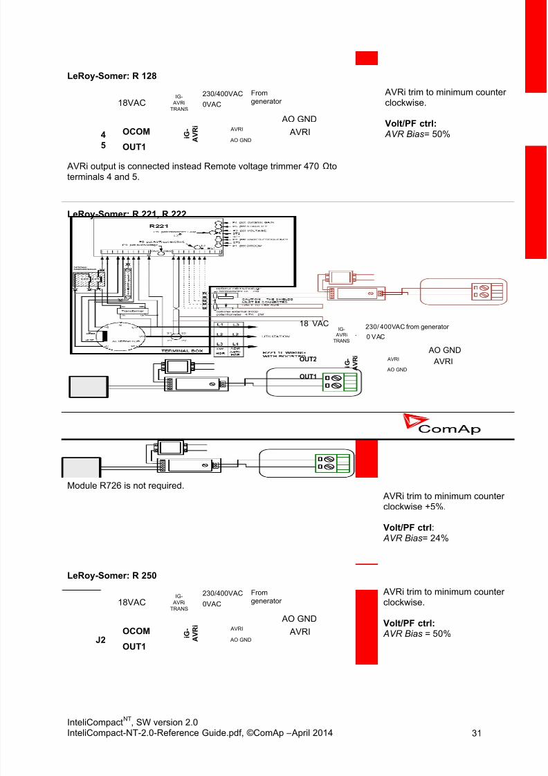
LeRoy-Somer: R 128
18VAC
From
generator
OUT1OCOM i G
-
A V
R i
230/400VAC
0VAC
AVRI
AO GND
45
AO GND
AVRI
IG-
AVRi
TRANS
AVRi output is connected instead Remote voltage trimmer 470 Ω toterminals 4 and 5.
AVRi trim to minimum counterclockwise.
Volt/PF ctrl:
AVR Bias = 50%
LeRoy-Somer: R 221, R 222
18 VAC from generator
i G -
A V R i
230/ 400VAC
0 VAC
OUT1
OUT2
AO GND
AVRI AO GND
AVRI
IG- AVRi
TRANS
Module R726 is not required.
AVRi trim to minimum counterclockwise +5%.
Volt/PF ctrl: AVR Bias = 24%
LeRoy-Somer: R 250
18VAC
From
generator
OUT1
OCOM i G -
A V R i
230/400VAC
0VAC
AVRI
AO GND
AO GND
AVRI
J2
IG-
AVRi
TRANS
AVRi trim to minimum counterclockwise.
Volt/PF ctrl: AVR Bias = 50%

8/15/2019 InteliCompact NT 2.0 Reference Guide
http://slidepdf.com/reader/full/intelicompact-nt-20-reference-guide 32/287
InteliCompactNT
, SW version 2.0InteliCompact-NT-2.0-Reference Guide.pdf, ©ComAp – April 2014 32
LeRoy-Somer: R 230
18VAC
From
generator
OUT1
OUT2 i G - A V R
i
230/400VAC
0VAC
AVRI
AO GND
J4
500
AVRI
AO GND
IG-
AVRi
TRANS
Remove Link J4 and replace instead of R500Primary voltage setting with resistors connected: 230 V
AVRi trim to minimum counterclockwise.
Volt/PF ctrl: AVR Bias = 50%
H INT :
Disconnect one wire (OUT 1), set voltage on running Generator to U = nom.Measure Voltage over ResistorDepending on Value, increase AVRi potentiometer to get Range.Set exact Value with Bias Voltage//PF regulation (gain = 0)
Stop gen-set and connect when equal Voltage and polarity is achieved.Set again in regulation loop on demand
LeRoy-Somer: R 230
from generator
i G -
A V R i
230/ 400VAC
0 VAC
AVRI
AO GND
OUT1
OUT2
AVRI
AO GND
IG-
AVRi
TRANS
Module R726 is not required. AVRi trim to minimum counter clockwise. Volt/PF ctrl:
AVR Bias = 50%

8/15/2019 InteliCompact NT 2.0 Reference Guide
http://slidepdf.com/reader/full/intelicompact-nt-20-reference-guide 33/287
InteliCompactNT
, SW version 2.0InteliCompact-NT-2.0-Reference Guide.pdf, ©ComAp – April 2014 33
LeRoy-Somer: R 449
From
generator
OUT1
OUT2
i G
-
A V
R i
230/400VAC
0VAC
AVRI
AO GND5
4
32
1
AVRI
AO GNDST4
IG-
AVRi
TRANS
AVRi trim to minimum counterclockwise
Volt/PF ctrl:
AVR Bias = 50%
Stamford3.15.2.2
STAMFORD SX 460
18VAC
From
generator
OUT1
OUT2 i G -
A V R i
230/400VAC
0VAC
AVRI
AO GND
12
AVRI
AO GND
IG-
AVRi
TRANS
AVRi output is connected instead of external resistor for voltage adjusting.
AVRi trim to approx. 60 %clockwise.
Volt/PF ctrl: AVR Bias = 60-70%
Voltage range (-6 V; 6 V)
H INT :
Before you connect IG-AVRi you should connect the jumper on AVR between pin 1 and 2 to run the voltageregulator without external control and set the voltage by the voltage trim on SX460 to roughly 227 V (in theevent that the nominal voltage of the system is 230 V).
STAMFORD SX 440, AS440, MX 321, SX 421
18VAC
From
generator
OUT1
OUT2 i G -
A V R i
230/400VAC
0VAC
AVRI
AO GND
A1A2
AVRI
AO GND
IG-
AVRi
TRANS
PFC3 module is not required.
AVRi trim to minimum counterclockwise.
Volt/PF ctrl: AVR Bias = 50%
STAMFORD AS480
18VACFrom
generator
OUT2
OCOM i G -
A V R i
230/400VAC
0VAC
AVRI
AO GND
AO GND
AVRI
IG-
AVRi
TRANS
1
2
AVRi output is connected instead of external resistor for voltage adjusting.
Volt/PF ctrl: AVR Bias = 30%

8/15/2019 InteliCompact NT 2.0 Reference Guide
http://slidepdf.com/reader/full/intelicompact-nt-20-reference-guide 34/287
InteliCompactNT
, SW version 2.0InteliCompact-NT-2.0-Reference Guide.pdf, ©ComAp – April 2014 34
STAMFORD MX 341
18VAC
From
generator
OUT1
OCOM i G - A V R
i
230/400VAC
0VAC
AVRI
AO GND
AO GND
AVRIA1A2
IG-
AVRi
TRANS
AVRi trim to minimum counterclockwise.
Volt/PF ctrl:
AVR Bias = 50%
H INT :
Disconnect the droop CT (terminal S1 & S2) and short the droop CT leads.Short the terminal S1,S2 on the AVR
AVK Newage3.15.2.3
AVK Newage Cosimat N+
18VAC
From
generator
OUT1
OCOM
i G -
A V R i
230/400VAC
0VAC
AVRI
AO GND
AO GND
AVRItS
2
1
5R5
250R
IG-
AVRi
TRANS
Volt/PF ctrl: AVR Bias = 25%
AVK Newage MA330, 327, 321, 341
18VAC
From
generator
OUT1
OUT2 i G -
A V R i
230/400VAC
0VAC
AVRI
AO GND
2
1
A1
A2
AVRI
AO GND
IG-
AVRiTRANS
AVRi trim to minimum counter
clockwise
Volt/PF ctrl: AVR Bias = 50%
Caterpillar3.15.2.4
Caterpillar CDVR
18VACFromgenerator
OUT1
OUT2 i G -
A V R i
230/400VAC0VAC
AVRI
AO GND
12-3
12-6
AVRI
AO GND
IG-
AVRiTRANS
AVRi trim to 50%
Volt/PF ctrl: AVR Bias = 50%

8/15/2019 InteliCompact NT 2.0 Reference Guide
http://slidepdf.com/reader/full/intelicompact-nt-20-reference-guide 35/287
InteliCompactNT
, SW version 2.0InteliCompact-NT-2.0-Reference Guide.pdf, ©ComAp – April 2014 35
Caterpillar DVR
18VAC
From
generator
OUT1
OCOM i G - A V R
i
230/400VAC
0VAC
AVRI
AO GND
AO GND
AVRI745
IG-
AVRi
TRANS
Pin 44 on DVR – PF regulation directly from DVR is not connected.
AVRi trim to 25%
Volt/PF ctrl: AVR Bias = 50%
Caterpillar VR6, VR3F
18VAC
From
generator
OUT1
OCOM i G -
A V R i
230/400VAC
0VAC
AVRI
AO GND
AO GND
AVRITR5TR6
TR7
IG-
AVRi
TRANS
For VR3F link 4-7 has to be removed.
AVRi trim to minimum counterclockwise.
Volt/PF ctrl: AVR Bias
Caterpillar VR6-B
18VAC
From
generator
OUT1
OUT2 i G -
A V R i
230/400VAC
0VAC
AVRI
AO GND
47
23
AVRI
AO GND
IG-
AVRi
TRANS
AVRi trim to minimum counterclockwise.
Volt/PF ctrl: AVR Bias = 0%
Voltage range (-2 V; 2 V)
Basler3.15.2.5
Basler: APR 63-5, AEC 63-7, KR-FX, KR-FFX
18VAC
From
generator
OUT1
OCOM i G -
A V R i
230/400VAC
0VAC
AVRI
AO GND
AO GND
AVRI76
IG-
AVRi
TRANS
AVRi output is connected instead of external resistor for voltage adjusting.
AVRi trim to minimum counterclockwise.
Volt/PF ctrl: AVR Bias = 50%
Basler: DECS 100
18VAC
From
generator
OUT1
OUT2 i G -
A V R i
230/400VAC
0VAC
AVRI
AO GND
BA
AVRI
AO GND
IG-
AVRi
TRANS
AVRi output is connected instead of external resistor for voltage adjusting.
AVRi trim to minimum counterclockwise.
Volt/PF ctrl: AVR Bias = 50%

8/15/2019 InteliCompact NT 2.0 Reference Guide
http://slidepdf.com/reader/full/intelicompact-nt-20-reference-guide 36/287
InteliCompactNT
, SW version 2.0InteliCompact-NT-2.0-Reference Guide.pdf, ©ComAp – April 2014 36
Basler: DESC 200
18VAC
From
generator
OUT1
OUT2
i G
-
A V
R i
230/400VAC
0VAC
AVRI
AO GND
A10A9
AVRI
AO GND
IG-
AVRi
TRANS
AVRi trim to minimum counterclockwise.
Volt/PF ctrl:
AVR Bias = 50%
Marathon3.15.2.6
Marathon DVR2000E
18VAC
From
generator
OUT1
OUT2
i G
-
A V
R i
230/400VAC
0VAC
AVRI
AO GND
BA
AVRI
AO GND
IG-
AVRi
TRANS
AVRi trim to 1/3 clockwise
Volt/PF ctrl: AVR Bias = 50%
Marathon PM100, 200
18VAC
From
generator
OUT1
OUT2 i G -
A V R i
230/400VAC
0VAC
AVRI
AO GND
6
7
AVRI
AO GND
IG- AVRi
TRANS
Volt/PF ctrl: AVR Bias = 50%
Marelli3.15.2.7
MarelliMotori Mark I (M40FA640A/A)
18VAC
From
generator
OUT1
OUT2 i G -
A V R i
230/400VAC
0VAC
AVRI
AO GND
86
AVRI
AO GND
IG-
AVRi
TRANS
Volt/PF ctrl: AVR Bias = 50%
MarelliMotori (M40FA610A)
18VAC
From
generator
OUT1
OUT2 i G -
A V R i
230/400VAC
0VAC
AVRI
AO GND
8
6
AVRI
AO GND
IG- AVRi
TRANS
Volt/PF ctrl: AVR Bias = 50%

8/15/2019 InteliCompact NT 2.0 Reference Guide
http://slidepdf.com/reader/full/intelicompact-nt-20-reference-guide 37/287
InteliCompactNT
, SW version 2.0InteliCompact-NT-2.0-Reference Guide.pdf, ©ComAp – April 2014 37
MarelliMotori Mark V (M16FA655A)
18VAC
From
generator
OUT1
OCOM i G -
A V R i
230/400VAC
0VAC
AVRIAO GND
AO GND
AVRIP
Q
IG- AVRi
TRANS
AVRi trim to 1/4 position
Volt/PF ctrl: AVR Bias = 15%
Mecc Alte SpA3.15.2.8
Mecc Alte SpA: U.V.R.6
18VAC
From
generator
OUT2
OCOM i G -
A V R i
230/400VAC
0VAC
AVRI
AO GND
AO GND
AVRI
IG-
AVRi
TRANS
AVRi output is connected instead of Remote voltage trimmer 100 KΩ (OUT2= top position wire and GND = second position from top).
AVRi trim to maximum
clockwise.
Volt/PF ctrl: AVR Bias = 75%
Mecc Alte SpA: S.R.7/2
18VAC
From
generator
OUT1
OCOM i G -
A V R i
230/400VAC
0VAC
AVRI
AO GND
AO GND
AVRI5B
7
IG-
AVRiTRANS
AVRi trim to maximum
clockwise.
Volt/PF ctrl: AVR Bias = 75%
Mecc Alte UVR
18VAC
From
generator
OUT1
OUT2 i G
-
A V
R i
230/400VAC
0VAC
AVRI
AO GND
86
AVRI
AO GND
IG- AVRi
TRANS
AVRi trim to maximumclockwise.
Volt/PF ctrl:
AVR Bias = 50%
Mecc Alte DER1
18VAC
From
generator
OUT1
OCOM i G -
A V R i
230/400VAC
0VAC
AVRI
AO GND
AO GND
AVRI2930
IG-
AVRi
TRANS
AVRi trim to 1/16 fromminimum.
Volt/PF ctrl: AVR Bias = 50%
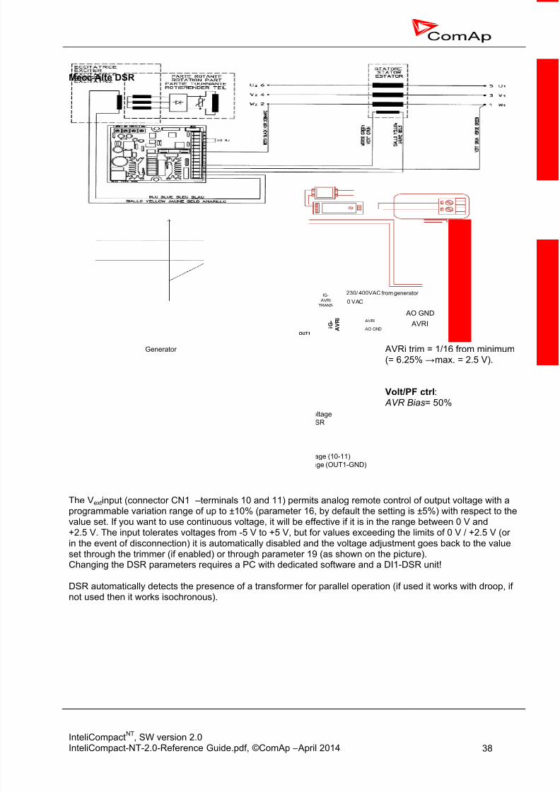
8/15/2019 InteliCompact NT 2.0 Reference Guide
http://slidepdf.com/reader/full/intelicompact-nt-20-reference-guide 38/287
InteliCompactNT
, SW version 2.0InteliCompact-NT-2.0-Reference Guide.pdf, ©ComAp – April 2014 38
Mecc Alte DSR
from generator
i G -
A V R i
230/ 400VAC
0 VAC
AVRI
AO GND
10
OCOM
11
OUT1 AO GND
AVRI
IG-
AVRiTRANS
100%
0V
114%
(or 105%)
86%
(or 95%)
1.25V 2.5V
Generator
voltage
Nominal voltageset on DSR
DSR input voltage (10-11)
IG-AVRi output voltage (OUT1-GND)
AVRi trim = 1/16 from minimum(= 6.25% → max. = 2.5 V).
Volt/PF ctrl: AVR Bias = 50%
The Vext input (connector CN1 – terminals 10 and 11) permits analog remote control of output voltage with aprogrammable variation range of up to ±10% (parameter 16, by default the setting is ±5%) with respect to thevalue set. If you want to use continuous voltage, it will be effective if it is in the range between 0 V and+2.5 V. The input tolerates voltages from -5 V to +5 V, but for values exceeding the limits of 0 V / +2.5 V (orin the event of disconnection) it is automatically disabled and the voltage adjustment goes back to the value
set through the trimmer (if enabled) or through parameter 19 (as shown on the picture).Changing the DSR parameters requires a PC with dedicated software and a DI1-DSR unit!
DSR automatically detects the presence of a transformer for parallel operation (if used it works with droop, ifnot used then it works isochronous).

8/15/2019 InteliCompact NT 2.0 Reference Guide
http://slidepdf.com/reader/full/intelicompact-nt-20-reference-guide 39/287
InteliCompactNT
, SW version 2.0InteliCompact-NT-2.0-Reference Guide.pdf, ©ComAp – April 2014 39
Piller3.15.2.9
Piller
18VAC
From
generator
OUT1
OUT2 i G -
A V R i
230/400VAC
0VAC
AVRI
AO GND
12
AVRI
AO GND
IG-
AVRi
TRANS
AVRi output is connected instead of Remote voltage trimmer 100 kΩ.
AVRi trim to minimum counterclockwise.
Volt/PF ctrl: AVR Bias = 39%
Marathon3.15.2.10
Marathon DVR2000E
18VAC
From
generator
OUT1
OUT2 i G -
A V R i
230/400VAC
0VAC
AVRI
AO GND
BA
AVRI
AO GND
IG-
AVRi
TRANS
AVRi trim to 1/3 clockwise
Volt/PF ctrl: AVR Bias = 50%
Marathon PM100, 200
18VAC
From
generator
OUT1
OUT2 i G -
A V R i
230/400VAC
0VAC
AVRI
AO GND
67
AVRI
AO GND
IG-
AVRi
TRANS
Volt/PF ctrl: AVR Bias = 50%
KATO3.15.2.11
KATO KCR 360
18VAC
From
generator
OUT1
OUT2 i G -
A V R i
230/400VAC
0VAC
AVRI
AO GND
86
AVRI
AO GND
IG-
AVRi
TRANS
Volt/PF ctrl: AVR Bias = 50%

8/15/2019 InteliCompact NT 2.0 Reference Guide
http://slidepdf.com/reader/full/intelicompact-nt-20-reference-guide 40/287
InteliCompactNT
, SW version 2.0InteliCompact-NT-2.0-Reference Guide.pdf, ©ComAp – April 2014 40
KATO KCR 760
18VAC
From
generator
OUT1
OUT2 i G -
A V R i
230/400VAC
0VAC
AVRI
AO GND
R2
R1
AVRI
AO GND
IG-
AVRi
TRANS
AVRi trim to minimum counterclockwise.
Volt/PF ctrl: AVR Bias = 45%
KATO K-65-12B
18VAC
From
generator
OUT1
OUT2 i G -
A V R i
230/400VAC
0VAC
AVRI
AO GND
23
AVRI
AO GND
IG-
AVRi
TRANS4
7
AVRi trim to minimum counterclockwise.
Volt/PF ctrl: AVR Bias = 50%
ENGGA3.15.2.12
ENGGA WT-2
AVRI
AO GND
18VAC
From
generator
OUT1 A V R i
230/400VAC
0VAC
AVRI
AO GND
IG- AVRi
TRANS
I G -OUT2A-
A+
AVRi trim to 1/3 clockwise
Volt/PF ctrl: AVR Bias = 50%
ENGGA WT-3
AVRI
AO GND
18VAC
From
generator
OUT1 A V R i
230/400VAC
0VAC
AVRI
AO GND
IG- AVRi
TRANS
I G -OUT2A2
A1
Volt/PF ctrl: AVR Bias = 50%
Sincro3.15.2.13
Sincro AVR BL3 or BL4
AVRI
AO GND
18VAC
From
generator
OUT1 A V R i
230/400VAC
0VAC
AVRI
AO GND
IG- AVRi
TRANS
I G -COMPOT
EXT
AVRi trim to middle position
Volt/PF ctrl: AVR Bias = 20%

8/15/2019 InteliCompact NT 2.0 Reference Guide
http://slidepdf.com/reader/full/intelicompact-nt-20-reference-guide 41/287
InteliCompactNT
, SW version 2.0InteliCompact-NT-2.0-Reference Guide.pdf, ©ComAp – April 2014 41
Kutai3.15.2.14
Kutai EA448
AVRI
AO GND
18VAC
From
generator
OUT1 A V R i
230/400VAC
0VAC
AVRI
AO GND
IG- AVRi
TRANS
I G -COM
ST4
AVRi output is connected instead of Remote voltage trimmer 470Ω toterminals ST4. Module R726 is not required.
AVRi trim to minimum counterclockwise.
Volt/PF ctrl: AVR Bias = 50%

8/15/2019 InteliCompact NT 2.0 Reference Guide
http://slidepdf.com/reader/full/intelicompact-nt-20-reference-guide 42/287
InteliCompactNT
, SW version 2.0InteliCompact-NT-2.0-Reference Guide.pdf, ©ComAp – April 2014 42
3.16 Speed governor interface
The speed governor output is used to control the speed or the power of the engine via the remotespeed controlling input provided by the speed governor.
The output from the controller can work in the following modes:
voltage mode 0 to 10 V
voltage mode 0 to 10 V with serial 10k resistor
5 V PWM mode
NOTE:The PWM mode is designed and optimized for Caterpillar governors. Since IC-NT SW v. 1.4.4 speedgovernor PWM frequency is fixed to 500 Hz.
The jumpers for speed governor output mode are shown on the picture below.
V o u t
V o u t R
P W M
The initial level of the governor output is adjustable by the setpoint Speed Gov Bias and thecharacteristic (positive or negative) can be selected by the setpoint Speed Gov Char .
The active range of the output can be adapted to the governor input range by setpoints
SpeedGovLowLim and SpeedGovHiLim. NOTE: Some governors may evaluate input voltage out of the allowed range as a faulty condition and theirfunctioning may be blocked.

8/15/2019 InteliCompact NT 2.0 Reference Guide
http://slidepdf.com/reader/full/intelicompact-nt-20-reference-guide 43/287
InteliCompactNT
, SW version 2.0InteliCompact-NT-2.0-Reference Guide.pdf, ©ComAp – April 2014 43
3.16.1 Speed governor list
Woodward3.16.1.1
VoutR16 COM15 ±
W O O D W A
R D
2 3 0 1 A
S p e e d C o n t r o l
SG + AO COM
Sync/Load Ctrl:
Speed Gov Bias = 5.00 VSpeedGovChar = POSITIVE
26 -
25 +
W
O O D W A R D
2 3 0 1 L S &
S
p e e
d c o n
t r o l
SG +
AO COM VoutR
Sync/Load Ctrl:Speed Gov Bias = 5.00 VSpeedGovChar = POSITIVE
VoutRGND:2
ILS:9
W O O D W A R D
D P G 2 2 0 1
SG +
AO COM
470k
For Woodward DPG 2223 the ILS terminal is 10.
Sync/Load Ctrl:Speed Gov Bias = 2.50 VSpeedGovChar = POSITIVESpeedGovLowLim = 0 VSpeedGovHiLim = 5 V
12 -
11+
W O O D W A R D
E P G
SG +
AO COM VoutR
Sync/Load Ctrl:Speed Gov Bias = 1.50 VSpeedGovChar = POSITIVESpeedGovLowLim = 0 V SpeedGovHiLim = 3 V
H INT :
For Woodward EPG speed governor (revision F) is in case of InteliCompactNT
limit:
Speed Gov Bias = 1 V SpeedGovLowLim = 0 V SpeedGovHiLim = 2 V
1 8 V A C
From
generator
AO COM
SG+
W O O D W A R D
E P G
O p
t i o n s
2
0VAC
i G -
A V R i
iG-AVRi
TRANS
230/400VAC
OUT1
OUT2
PWM
Sync/Load Ctrl:Speed Gov Bias = 5.00 VSpeedGovChar = POSITIVE
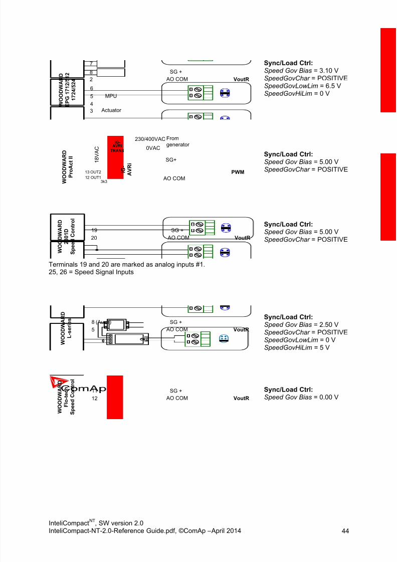
8/15/2019 InteliCompact NT 2.0 Reference Guide
http://slidepdf.com/reader/full/intelicompact-nt-20-reference-guide 44/287
InteliCompactNT
, SW version 2.0InteliCompact-NT-2.0-Reference Guide.pdf, ©ComAp – April 2014 44
2
8
W O O D W A R D
E P G
1 7 1 2 / 5 1 2
1 7 2 4 / 5 2 4
SG +
AO COM VoutR
7
45
6
3
MPU
Actuator
Sync/Load Ctrl:Speed Gov Bias = 3.10 VSpeedGovChar = POSITIVESpeedGovLowLim = 6.5 VSpeedGovHiLim = 0 V
1 8 V A C
From
generator
AO COM
SG+
W O O D W A R D
P r o A c t I I
0VAC
i G -
A V R i
iG-AVRi
TRANS
230/400VAC
12 OUT1
13 OUT2 PWM
3k3
Sync/Load Ctrl:Speed Gov Bias = 5.00 VSpeedGovChar = POSITIVE
20
19
W O O D W A R D
2 3 0 1 D
S p e e d C o n t r o l
SG +
AO COM VoutR
Terminals 19 and 20 are marked as analog inputs #1.25, 26 = Speed Signal Inputs
Sync/Load Ctrl:Speed Gov Bias = 5.00 VSpeedGovChar = POSITIVE
5
8 (Aux1)
W O O D W A R D
L - s e r i e s
SG +
AO COM VoutR
Sync/Load Ctrl:Speed Gov Bias = 2.50 VSpeedGovChar = POSITIVESpeedGovLowLim = 0 VSpeedGovHiLim = 5 V
12
11
W O O D W
A R D
F l o - t e c
h
S p e e
d C o n
t r o l
SG +
AO COM VoutR
Sync/Load Ctrl:Speed Gov Bias = 0.00 V

8/15/2019 InteliCompact NT 2.0 Reference Guide
http://slidepdf.com/reader/full/intelicompact-nt-20-reference-guide 45/287
InteliCompactNT
, SW version 2.0InteliCompact-NT-2.0-Reference Guide.pdf, ©ComAp – April 2014 45
Cummins3.16.1.2
20
11
C
u m m i n s
Q S T 3 0 SG +
AO COM VoutR
Sync/Load Ctrl:Speed Gov Bias = 5.00 VSpeedGovChar =
POSITIVE
A1
I9
C u m m i n s
E C P G SG +
AO COMVout
Sync/Load Ctrl:Speed Gov Bias = 5.00 VSpeedGovChar =
POSITIVE
Pay attention to the connector and jumper orientation.
0V
5V
C u m m i n s
O N A N SG +
AO COM VoutR
10k
Sync/Load Ctrl:Speed Gov Bias = 5.00 VSpeedGovChar =
POSITIVE
11 C u m m i n s
E F C
SG +
AO COM VoutR8
4µ7/50V
200k
Sync/Load Ctrl:Speed Gov Bias = 6.40 VSpeedGovChar =POSITIVESpeedGovLowLim = 5 VSpeedGovHiLim = 7.8 V
Setting at 1500 RPM: Primary setting governor with disconnected speed regulation lines.
32
9
C u m m i n s
Q S L 9 SG +
AO COM
Vout
Sync/Load Ctrl:Speed Gov Bias = 3.50 VSpeedGovChar =POSITIVESpeedGovLowLim = 2.5 VSpeedGovHiLim = 5 V

8/15/2019 InteliCompact NT 2.0 Reference Guide
http://slidepdf.com/reader/full/intelicompact-nt-20-reference-guide 46/287
InteliCompactNT
, SW version 2.0InteliCompact-NT-2.0-Reference Guide.pdf, ©ComAp – April 2014 46
03-12
03-11
C u m m i n s
G C S
SG +
AO COM VoutR
Sync/Load Ctrl:Speed Gov Bias = 5.00 VSpeedGovChar =POSITIVESpeedGovLowLim = 2.5 VSpeedGovHiLim = 7.5 V
Caterpillar3.16.1.3
19
9
C a t e r p i l l a r
P E E C SG +
AO COM
PWM
Pay attention to the connector and jumper orientation.
1
2
C a t e r p i l l a r
S i g n a l
C o n v e r t e r
SG +
AO COM VoutR
67k7
Sync/Load Ctrl:Speed Gov Bias = 5.10 VSpeedGovChar = POSITIVESpeedGovLowLim = 0 VSpeedGovHiLim = 10 V
10
12
C a t e r p i l l a r
A D E M SG +
AO COM
PWM
MTU3.16.1.4
36
8
M T U M D
E C
2 0 0 0 , 4 0 0 0
SG + AO COM
Vout
Sync/Load Ctrl:Speed Gov Bias = 4.90 V
SpeedGovChar =POSITIVESpeedGovLowLim = 0 VSpeedGovHiLim = 10 V
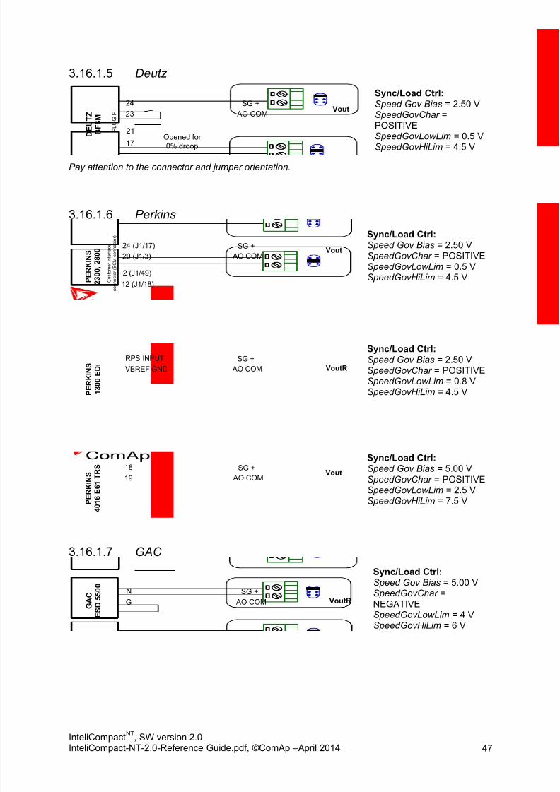
8/15/2019 InteliCompact NT 2.0 Reference Guide
http://slidepdf.com/reader/full/intelicompact-nt-20-reference-guide 47/287
InteliCompactNT
, SW version 2.0InteliCompact-NT-2.0-Reference Guide.pdf, ©ComAp – April 2014 47
Deutz3.16.1.5
23
24
D E U T Z
B F 6 M
SG +
AO COM Vout
P L U G
F
17
21
Opened for0% droop
Sync/Load Ctrl:Speed Gov Bias = 2.50 VSpeedGovChar =POSITIVE
SpeedGovLowLim = 0.5 VSpeedGovHiLim = 4.5 V
Pay attention to the connector and jumper orientation.
Perkins3.16.1.6
20 (J1/3)
24 (J1/17)
P E
R K I N S
2 3 0 0 , 2 8 0 0
SG +
AO COMVout
12 (J1/18)
2 (J1/49) C u s t o m e r i n t e r f a c e
c o n n e c
t o r ( E C M
c o n n e c t o r )
Sync/Load Ctrl:Speed Gov Bias = 2.50 VSpeedGovChar = POSITIVESpeedGovLowLim = 0.5 V
SpeedGovHiLim = 4.5 V
VBREF GND
RPS INPUT
P E R K I N S
1 3 0 0 E D i
SG +
AO COM VoutR
Sync/Load Ctrl:Speed Gov Bias = 2.50 VSpeedGovChar = POSITIVESpeedGovLowLim = 0.8 VSpeedGovHiLim = 4.5 V
19
18
P E R K I N S
4 0 1 6 E 6 1 T R S SG +
AO COM Vout
Sync/Load Ctrl:Speed Gov Bias = 5.00 VSpeedGovChar = POSITIVESpeedGovLowLim = 2.5 VSpeedGovHiLim = 7.5 V
GAC3.16.1.7
G
N
G A C
E S D 5 5 0 0
SG +
AO COM VoutR
Sync/Load Ctrl:Speed Gov Bias = 5.00 VSpeedGovChar =NEGATIVESpeedGovLowLim = 4 VSpeedGovHiLim = 6 V

8/15/2019 InteliCompact NT 2.0 Reference Guide
http://slidepdf.com/reader/full/intelicompact-nt-20-reference-guide 48/287
InteliCompactNT
, SW version 2.0InteliCompact-NT-2.0-Reference Guide.pdf, ©ComAp – April 2014 48
G
M
G A C
E S D 5 3 3 0
SG +
AO COM VoutR AUX
Sync/Load Ctrl:Speed Gov Bias = 5.00 VSpeedGovChar =NEGATIVE
2
25
G A C
E G S 1 0 4 B
SG +
AO COM VoutR
Sync/Load Ctrl:Speed Gov Bias = 5.00 VSpeedGovChar =NEGATIVESpeedGovLowLim = 4 VSpeedGovHiLim = 6 V
L
A
G A C
S D G 7 3 5
SG +
AO COM VoutR
Sync/Load Ctrl:Speed Gov Bias = 5.00 VSpeedGovChar =NEGATIVESpeedGovLowLim = 2.5 VSpeedGovHiLim = 7.5 VTauSpeedActuat = 1 s
Barber Colman3.16.1.8
2
9
B a r b e r C o l m a n
D Y N A 8 0 0 0
SG +
AO COM VoutR
Sync/Load Ctrl:Speed Gov Bias = 6.00 VSpeedGovChar = POSITIVESpeedGovLowLim = 4 VSpeedGovHiLim = 8 V
2
9
B a r b e
r C o l m a n
D Y N
1 1 0 6 8 4
SG +
AO COM VoutR
Sync/Load Ctrl:Speed Gov Bias = 6.00 VSpeedGovChar = POSITIVESpeedGovLowLim = 4 VSpeedGovHiLim = 8 V
Heinzmann3.16.1.9
2
9
H e i n z m a n E 6
SG +
AO COM VoutR
150k
Sync/Load Ctrl:Speed Gov Bias = 0.00 VSpeedGovChar = POSITIVE

8/15/2019 InteliCompact NT 2.0 Reference Guide
http://slidepdf.com/reader/full/intelicompact-nt-20-reference-guide 49/287
InteliCompactNT
, SW version 2.0InteliCompact-NT-2.0-Reference Guide.pdf, ©ComAp – April 2014 49
2
9
H e i n z m a n
E 1 6 SG +
AO COM VoutR
Sync/Load Ctrl:Speed Gov Bias = 0.00 VSpeedGovChar = POSITIVE
3
4
H e i n z m a n
K G - 1 - 0 3 F
SG +
AO COM VoutR
5
GND
Sync/Load Ctrl:Speed Gov Bias = 0.00 VSpeedGovChar = POSITIVE
3 (A3)
1 (B3)
H e i n z m a n
P A N D A R O S
D C 6 SG +
AO COM VoutR
10k
Terminals A3 and B3 are on OEM 14-pin connector.Mounted on Perkins 40xx engines.
Sync/Load Ctrl:Speed Gov Bias = 5.00 VSpeedGovChar = POSITIVESpeedGovLowLim = 0.8 VWithout resistorSpeed Gov Bias = 2.75 V SpeedGovLowLim = 0 VSpeedGovHiLim = 6 V
Toho3.16.1.10
8
11
T O H O SG +
AO COM VoutR
10k
Sync/Load Ctrl:Speed Gov Bias = 4.00 VSpeedGovChar = POSITIVE
ComAp3.16.1.11
7
8
E C O N 4
SG +
AO COMVout
Sync/Load Ctrl:Speed Gov Bias = 5.1 VSpeedGovChar =POSITIVESpeedGovLowLim = 0 VSpeedGovHiLim = 10 V

8/15/2019 InteliCompact NT 2.0 Reference Guide
http://slidepdf.com/reader/full/intelicompact-nt-20-reference-guide 50/287
InteliCompactNT
, SW version 2.0InteliCompact-NT-2.0-Reference Guide.pdf, ©ComAp – April 2014 50
3.17 CAN bus wir in g
The wiring of the CAN bus communication should be provided in such a way that the following rulesare observed:
The maximum length of the CAN bus depends on the communication speed. For a speed of
250 kbps, which is used on the CAN1 bus (extension modules, ECU) and CAN2 bus if it isswitched to 32C mode, the maximum length is 200 m. If the CAN2 bus is switched to 8C modethe speed is 50 kbps and the maximum length is 800 m.
The bus must be wired in linear form with termination resistors at both ends. No nodes areallowed except on the controller terminals.
NOTE: A termination resistor at the CAN is already implemented on the PCB. For connecting, closethe jumper near the appropriate CAN terminal.
Use a cable with following parameters:
Cable type Shielded twisted pair
Impedance 120 Ω
Propagation velocity ≥ 75% (delay ≤ 4.4 ns/m)
Wire crosscut ≥ 0.25 mm2
Attenuation (@1MHz) ≤ 2dB/100 m
120R120R
CAN BUS TOPOLOGY
NOTE:
See the website www.can-cia.org for information about the CAN bus, specifications, etc.

8/15/2019 InteliCompact NT 2.0 Reference Guide
http://slidepdf.com/reader/full/intelicompact-nt-20-reference-guide 51/287
InteliCompactNT
, SW version 2.0InteliCompact-NT-2.0-Reference Guide.pdf, ©ComAp – April 2014 51
3.18 Recommended CAN/RS485 con nect ion
3.18.1 CAN bus connection
The bus has to be terminated by 120 Ω resistors at both ends. External units can be connected on the
CAN bus line in any order, but keeping a line arrangement (no tails, no star) is necessary. Standardmaximum bus length is 200 m for 32C CAN BUS MODE and 900 m for 8C CAN BUS MODE. Shieldedcable must be used. Shielding has to be connected to PE on one side (controller side).
1. For shorter distances (all network components within one room) – picture 1Interconnect H and L; shielding connect to PE on controller side
2. For longer distances (connection between rooms within one building) – picture 2Interconnect H, L, COM; shielding connect to PE at one point
3. In case of surge hazard (connection out of building in case of storm etc.) – picture 3We recommend using the following protections:
Phoenix Contact (http://www.phoenixcontact.com): PT 5-HF-12DC-ST with PT2x2-BE(base element)
Saltek (http://www.saltek.cz): DM-012/2 R DJ
Recommended data cables: BELDEN (http://www.belden.com)
1. For shorter distances: 3105A Paired – EIA Industrial RS-485 PLTC/CM (1x2 conductors)2. For longer distances: 3106A Paired – EIA Industrial RS-485 PLTC/CM (1x2+1 conductors)3. In case of surge hazard: 3106A Paired – EIA Industrial RS-485 PLTC/CM (1x2+1 conductors)
3.18.2 RS485 connection
The line has to be terminated by 120 Ω resistors at both ends. External units can be connected on theRS485 line in any order, but keeping a line arrangement (no tails, no star) is necessary. Standard
maximum link length is 1000 m. Shielded cable must be used. Shielding has to be connected to PE onone side (controller side).
1. For shorter distances (all network components within one room) – picture 1interconnect A and B; shielding connect to PE on controller side
2. For longer distances (connection between rooms within one building) – picture 2interconnect A, B, COM; shielding connect to PE at one point
3. In case of surge hazard (connection out of building in case of storm etc.) – picture 3
We recommend using the following protections:
Phoenix Contact (http://www.phoenixcontact.com): PT 5-HF-5DC-ST with PT2x2-BE
(base element)(or MT-RS485-TTL) Saltek (http://www.saltek.cz): DM-006/2 R DJ
Recommended data cables: BELDEN (http://www.belden.com)
1. For shorter distances: 3105A Paired – EIA Industrial RS-485 PLTC/CM (1x2 conductors)2. For shorter distances: 3105A Paired – EIA Industrial RS-485 PLTC/CM (1x2 conductors)3. In case of surge hazard: 3106A Paired – EIA Industrial RS-485 PLTC/CM (1x2+1 conductors)

8/15/2019 InteliCompact NT 2.0 Reference Guide
http://slidepdf.com/reader/full/intelicompact-nt-20-reference-guide 52/287
InteliCompactNT
, SW version 2.0InteliCompact-NT-2.0-Reference Guide.pdf, ©ComAp – April 2014 52
H/A
L/BCOM
120 Ω
H/A
L/BCOM
120 Ω
PICTURE 1 – SHORTER DISTANCES ( ALL NETWORK COMPONENTS WITHIN ONE ROOM)
C A N 1
HCOM
L
C A N 2
120
1.IC-NT
Addr.: 1 Addr.: 1
C A N 1
Extension
module
C A N 1
C A N 22.
120
HCOM
L
HCOM
L
HCOM
L
HCOM
L
120
IC-NT
PICTURE 2 – LONGER DISTANCES (CONNECTION BETWEEN ROOMS WITHIN ONE BUILDING)
H/A
L/B
COM
120 ΩPT5-HF-12DC-ST (CAN)
PT5HF-5DC-ST (RS485)
H/A
L/B
COM
120 Ω
OUTINOUT
1
5
7
9
3
11
2
6
8
12
10
4
IN
1
5
7
9
3
11
2
6
8
12
10
4
PICTURE 3 – SURGE HAZARD (CONNECTION OUT OF BUILDING IN CASE OF STORM ETC.)

8/15/2019 InteliCompact NT 2.0 Reference Guide
http://slidepdf.com/reader/full/intelicompact-nt-20-reference-guide 53/287
InteliCompactNT
, SW version 2.0InteliCompact-NT-2.0-Reference Guide.pdf, ©ComAp – April 2014 53
3.19 Extension modu les
Extension modules are to be enabled and configured using LiteEdit. Extension modules are notcontained in the factory default configuration.
3.19.1 IGS-PTM
The IGS-PTM is a DIN Rail mounted extension module that is connected to the controller via a CAN1bus. The module contains:
8 binary inputs with the same properties and configuration as binary inputs of the controller.
8 binary outputs with the same properties and configuration as binary outputs of the controller.
4 analog inputs with selectable electrical range by a jumper: 0 –250 Ω, 0 –100 mV, 0 –20 mA,suitable for Pt100 and thermocouple sensors
NOTE: The controller selection jumper (iS/iG) must be in the iG position for using the module with theInteliCompact
NT.
A separate manual for the IGS-PTM module is available for download on the ComAp web site

8/15/2019 InteliCompact NT 2.0 Reference Guide
http://slidepdf.com/reader/full/intelicompact-nt-20-reference-guide 54/287
InteliCompactNT
, SW version 2.0InteliCompact-NT-2.0-Reference Guide.pdf, ©ComAp – April 2014 54
3.19.2 IGL-RA15 remote annunciator
The IGL-RA15 module is a remote annunciator that is connected to the controller via a CAN1 bus. Themodule contains:
15 LEDs with configurable colour (red, green, yellow).
Binary output for driving an external siren. Horn reset and Lamp test buttons.
The siren is activated automatically if a new yellow or red LED switches on, the duration is adjustableand it can be silenced by pressing the horn reset button. In the controller the LEDs are configured likebinary outputs, so all binary output functions can be used to drive the LEDs.
NOTE: THE ADDRESS SELECTION JUMPERS MUST BE IN THE IG POSITION FOR USING THE MODULE WITH THE
INTELICOMPACTNT
.
A separate manual for the IGL-RA15 module is available for download on the ComAp website

8/15/2019 InteliCompact NT 2.0 Reference Guide
http://slidepdf.com/reader/full/intelicompact-nt-20-reference-guide 55/287
InteliCompactNT
, SW version 2.0InteliCompact-NT-2.0-Reference Guide.pdf, ©ComAp – April 2014 55
3.19.3 IL-NT-AOUT8
The IL-NT-AOUT8 module is to be directly plugged-in into the slot on the rear side of the controller.The module contains 8 PWM open collector type outputs. The outputs are specially designed fordriving analog automotive type gauges. Any of the analog values measured or computed in thecontroller can be configured to each output and it is possible to configure a different conversion
characteristic (curve) for each output.NOTE: The module is compatible with gauges originally designed for resistive sensors, i.e. they have boardvoltage compensation. These gauges have 3 terminals: +BATT, SENSOR, GND.
GND
AO8
GND
+12/24V
AO1
AO6
AO5
AO4
AO3
AO2
AO7
AO8
Automotive
type gauge
+ BATT
- BATT
Examples of automotive gauges that can be used with the module:
VDO Oil pressure gauge 0 –10 Bar, p.n. 350-010-007
VDO Coolant temperature gauge 40 –120 °C, p.n. 310-010-002
VDO Fuel level 0-1/1, p.n. 301-010-001
3.19.4 IL-NT BIO8
Hybrid binary input/output module
IL-NT BIO8 is an optional plug-in card. Through this card the controller can accommodate up to 8binary inputs or outputs. In the LiteEdit PC configuration tool (version 4.4 and higher) it is possible toeasily choose if a particular I/O will be binary input or output.

8/15/2019 InteliCompact NT 2.0 Reference Guide
http://slidepdf.com/reader/full/intelicompact-nt-20-reference-guide 56/287
InteliCompactNT
, SW version 2.0InteliCompact-NT-2.0-Reference Guide.pdf, ©ComAp – April 2014 56
To insert the module, you must open the cover first (use a screwdriver to open) and then insert themodule into the slot. Once you have inserted it, the module will snap under the plastic teeth. It issupposed to be installed permanently. Should you need to remove it, the safest way is to remove theentire back cover and then remove the module manually. Installing the IL-NT BIO8 module is similar toinstalling the RS 232 module. The difference is that module fits into the “extension module” slot andafter installing the IL-NT BIO8 you do not put the small cover back.
BATT-
BATT-
BIO1
BIO2
BIO3
BIO4
BIO5
BIO6
BIO7
BIO8
IN
IN
OUT
K2K21
K11
SW1
BATT+
REL
K1
+ -
BATTERY
Technical details:IL-NT BIO8 plugs into the InteliCompact
NT controller EXTENSION MODULE port.
8 dedicated pins of the plug-in card’s terminal can be configured as binary inputs or outputs.
BINARY INPUTS
Number of inputs 8
Input resistance 4.7 kΩ
Input range 0 –36 V DC
Voltage level for close contact indication (Logical 1) < 0.8 V DC
Voltage level for open contact indication (Logical 0) > 2 V DC
Max voltage level for open contact indication 8 –36 V DC
BINARY OPEN COLLECTOR OUTPUTS
Number of outputs 8
Maximum current per pin 0.5 A
Maximum switching common current 2 A
Maximum switching voltage 36 V DC
NOTE: Binary inputs are not galvanically isolated.

8/15/2019 InteliCompact NT 2.0 Reference Guide
http://slidepdf.com/reader/full/intelicompact-nt-20-reference-guide 57/287
InteliCompactNT
, SW version 2.0InteliCompact-NT-2.0-Reference Guide.pdf, ©ComAp – April 2014 57
3.19.5 IC-NT CT-BIO7
Hybrid current input and binary input/output module (SPtM)
IC-NT CT-BIO7 is an optional plug-in card. Through this card the controller can accommodate one AC current (CT) measuring input and up to 7 binary inputs or outputs. In the LiteEdit PC configurationtool (version 4.4 and higher) it is possible to easily choose if particular I/O will be binary input or
output.
NOTE: Current measuring input is intended to measure one phase (AC) current of mains and to limitExport/Import to/from mains to zero value during parallel to mains operation. This is the case of theSPtM application, so current input of the IC-NT CT-BIO7 module is useful for SPtM controllers only.
To insert the module, you must open the cover first (use a screwdriver to open) and then insert themodule into the slot. Once you have inserted it, the module will snap under the plastic teeth. It issupposed to be installed permanently. Should you need to remove it, the safest way is to remove theentire back cover and then remove the module manually. Installing the IC-NT CT-BIO7 module issimilar to installing the RS 232 module. The difference is that module fits into the “extension module”slot and after installing the IC-NT CT-BIO7 you do not put the small cover back.
BATT-
BIO7
CT l
CT k
BIO1
BIO2
BIO3
BIO4
BIO5
BIO6
IN
IN
OUT
K2K21
K11
SW1
BATT+
REL
K1
+ -
BATTERY
MAINSKL
l k
0-5A
L3
Technical details:IC-NT CT-BIO7 plugs into InteliCompact
NT controller EXTENSION MODULE port.
7 dedicated pins of the plug-in card’s terminal can be configured as binary inputs or outputs.
CURRENT MEASURING INPUT
Number of inputs 1
Nominal input current (from CT) 5 A
Load (CT output impedance) < 0.1
Max measured current from CT 10 A
Current measurement tolerance 2% from Nominal current
Max peak current from CT 150 A / 1 s
Max continuous current 10 A
(All values in RMS)

8/15/2019 InteliCompact NT 2.0 Reference Guide
http://slidepdf.com/reader/full/intelicompact-nt-20-reference-guide 58/287
InteliCompactNT
, SW version 2.0InteliCompact-NT-2.0-Reference Guide.pdf, ©ComAp – April 2014 58
BINARY INPUTS
Number of inputs 7
Input resistance 4.7 kΩ
Input range 0 –36 V DC
Voltage level for close contact indication (Logical 1) < 0.8 V DC
Voltage level for open contact indication (Logical 0) > 2 V DC
Max voltage level for open contact indication 8 –36 V DC
BINARY OPEN COLLECTOR OUTPUTS
Number of outputs 7
Maximum current per pin 0.5 A
Maximum switching common current 2 A
Maximum switching voltage 36 V DC
NOTE: Binary inputs are not galvanically isolated.
Usage of CT measuring via the IC-NT CT-BIO7 module:
- Earth Fault current protection
- Peak Load shaving function
Earth fault current measurement3.19.5.1
The Earth Fault protection is done by the extension module IC-NT-BIO7.
When the measured current exceeds the set value, which indicates that part of the current isdispersed to earth, and when the set Earth Fault Del time elapses, the Earth Fault Sd protection and AL EarthFault output are activated. Earth Fault protection is not active when gen-set does not run andthe Im/EF input parameter is not set to “EarthFltC”.
Earth Fault Del
Earth Fault Sd
E a r t
h
F a u l t [ A ]
Time [s]
Time [s]
0
1AL Earth Fault
CAUTION!
Earth fault current measurement is not intended to protect human health, but the machines!

8/15/2019 InteliCompact NT 2.0 Reference Guide
http://slidepdf.com/reader/full/intelicompact-nt-20-reference-guide 59/287
InteliCompactNT
, SW version 2.0InteliCompact-NT-2.0-Reference Guide.pdf, ©ComAp – April 2014 59
3.20 Communicat ion modules
A communication module enables connection of a remote computer or other remote device such as aPLC to the controller. The module is to be plugged-in into the slot in the rear side of the controller. Theslot is accessible after the slot cover is removed.
More information about how to use communication modules can be found in the chapterCommunications.
SLOT FOR COMMUNICATION MODULES
NOTE: The modules are compatible with the IL-NT controllers also.
3.20.1 IL-NT RS232
This module contains a RS232 port with all modem signals connected internally to the COM1 of thecontroller. DB9M connector is used on the RS232 side.
2
3
5
2
3
5
SERIAL “CROSS-WIRED” CABLE
D B 9 M
D B 9 M
To PC COM
port
To controller
RS232 port
RS232 PINOUT AND CABLE WIRING

8/15/2019 InteliCompact NT 2.0 Reference Guide
http://slidepdf.com/reader/full/intelicompact-nt-20-reference-guide 60/287
InteliCompactNT
, SW version 2.0InteliCompact-NT-2.0-Reference Guide.pdf, ©ComAp – April 2014 60
3.20.2 IL-NT RS232-485
The IL-NT RS232-485 is a dual port module with RS232 and RS485 interfaces at independent COMchannels. The RS232 is connected to COM1 and RS485 to COM2.
RS232
COM1
RS485
COM2
A (RxTx +)
B (RxTx -)
GND
RS485 120R
terminator jumper
Boot jumper
RS485
balancing
resistor
jumpers
Terminator
Balancing
resistor
A
GND
BBalancing
resistor
+5V
A
B
GND
RS485 internal
wiring
IL-NT RS232-485 MODULE
3.20.3 IL-NT S-USB
This module contains a USB slave port connected internally to the COM1 of the controller and isdesigned as an easily removable service module.
This module requires a FTDI USB Serial converter driver installed in the PC. The driver creates avirtual serial port (COM) in the PC, which must be used in LiteEdit as communication port when aconnection is being opened.
NOTE: The FTDI driver is installed together with LiteEdit.
NOTE: When the USB cable from the controller is plugged for the first time into different USB ports on the PCincluding USB hubs, it may be recognized as new hardware and the drivers will be installed again witha different number of the virtual serial port.
CAUTION! Use a shielded USB cable only!

8/15/2019 InteliCompact NT 2.0 Reference Guide
http://slidepdf.com/reader/full/intelicompact-nt-20-reference-guide 61/287
InteliCompactNT
, SW version 2.0InteliCompact-NT-2.0-Reference Guide.pdf, ©ComAp – April 2014 61
3.20.4 IB-Lite
IB-Lite is a plug-in module with Ethernet 10/100 Mbit interface in RJ45 connector. The module isinternally connected to both COM1 and COM2 serial channels and provides an interface forconnecting a PC with LiteEdit or InteliMonitor through an Ethernet/internet network, for sending activee-mails and for integration of the controller into a building management (Modbus/TCP protocol).
“Restore
default
settings”
jumper
RJ45
Ethernet
IB-LITE MODULE
Use an Ethernet UTP cable with a RJ45 connector for linking the module with your Ethernet network.The module can also be connected directly to a PC using cross-wired UTP cable.
12
3
4
5
6
7
8
12
3
4
5
6
7
8
CROSS-WIRED UTP 10/100Mbit
CABLE
RJ45 RJ45
CROSS-WIRED UTP CABLE

8/15/2019 InteliCompact NT 2.0 Reference Guide
http://slidepdf.com/reader/full/intelicompact-nt-20-reference-guide 62/287
InteliCompactNT
, SW version 2.0InteliCompact-NT-2.0-Reference Guide.pdf, ©ComAp – April 2014 62
The communication module IB-Lite works with:
WebSupervisor – internet-based remote monitoring solution
AirGate – powerful connection technology to make internet access as simple as possible
NOTE: The module requires some setup before initial usage. See the chapter IB-Lite setup procedure.
3.20.5 IL-NT GPRS
This plug-in module is a GSM/GPRS modem which can work in two modes of operation based on thesettings in the setpoint COM1 Mode.
Settings DIRECT = the module works in a GPRS network and enables connection via AirGateto LiteEdit and WebSupervisor as well as sending SMS alarms.
Settings MODEM = the module works as a standard GSM modem enabling a CSD (CircuitSwitch Data) connection to the controller with LiteEdit or InteliMonitor and sending SMSalarms.
IL-NT GPRS MODULE AND GSM/GPRS SCREEN ON IC-NT DISPLAY
The communication module IL-NT GPRS works with:
WebSupervisor – internet-based remote monitoring solution
AirGate – powerful connection technology to make internet access as simple as possible
Locate – localization technology
NOTE: GPRS and CSD services must be provided by your GSM/GPRS operator for successful operation.
NOTE: THE GPRS AND CSD CONNECTION SHOULD NOT BE USED FOR THE FIRMWARE UPDATE PROCESS . USE
INSTEAD A WIRED CONNECTION LIKE RS232, USB, RS485 OR ETHERNET VIA IB-LITE!
NOTE:
It is necessary to power the controller and individually the IL-NT GPRS module as well.
WARNING

8/15/2019 InteliCompact NT 2.0 Reference Guide
http://slidepdf.com/reader/full/intelicompact-nt-20-reference-guide 63/287
InteliCompactNT
, SW version 2.0InteliCompact-NT-2.0-Reference Guide.pdf, ©ComAp – April 2014 63
Any manipulation of the IL-NT GPRS module should be done only without voltage.
SMS Commands3.20.5.1
To control the gen-set equipped with InteliCompactNT
controller and IL-NT GPRS communicationmodule (or modem) via SMS requests, send an SMS in the structure of:
# xxxx, yyyy, zzzz, etc.
to the telephone number of the SIM card in your IL-NT-GPRS module (or modem). Where the “#” mark
means the controller access code, “xxxx” means the Command 1, “yyyy” is Command 2, “zzzz” is
Command 3, etc.
Table of SMS requests:start Start the engine in MAN mode.
stop Stop the engine in MAN mode.
fault reset Acknowledging alarms and deactivating the horn output.
gcb close Closing GCB in MAN and TEST mode.
gcb open Opening GCB in MAN and TEST mode.
mcb close Closing MCB in MAN and TEST mode (only in IC-NT SPTM).mcb open Opening MCB in MAN and TEST mode (only in IC-NT SPTM).
off Switching to OFF mode.
man Switching to MAN mode.
aut Switching to AUT mode.
test Switching to TEST mode.
status Get status information from controller unit.
help Get a list of available SMS requests.
Example:
When the controller, in AUT mode, with a controller name of “IC-NT-Test”, with the IL-NT
GPRS module and access code “0” receives the SMS:
0 man, start, d10, gcb close, d300, gcb open, d30, stop, d30, aut
the mode will be changed to MANUAL. The engine will be started and after 10 s thecontroller will start the synchronization process and the GCB will close. After 300 s (fromthe point of starting synchronization) the GCB will open (after the “GCB Opens Del”setpoint), the engine will stop with a 30 s delay and it will go into AUT mode.
The controller will send back the SMS:
#IC-NT-Test:man<OK>,start<OK>,d_ok,gcb_close<OK>,d_ok,
gcb_open<OK>,d_ok,stop<OK>,d_ok,aut<OK>
if all conditions are correct.
NOTE:
The value “OK” in an SMS means that the command was successfully transmitted to the controller.
Potential errors/alarms during execution of commands are shown in Event SMS if is set (as isdescribed below).
Event SMS3.20.5.2
The InteliCompact
NT
controller equipped with the IL-NT GPRS communication module is able to sendEvent SMS according to the setting in the SMS/Email setpoint group:

8/15/2019 InteliCompact NT 2.0 Reference Guide
http://slidepdf.com/reader/full/intelicompact-nt-20-reference-guide 64/287
InteliCompactNT
, SW version 2.0InteliCompact-NT-2.0-Reference Guide.pdf, ©ComAp – April 2014 64
Event Msg – enable/disable sending of event SMS
Tel No/Addr Ch1 or Tel No/Addr Ch2 – field for administrator ’s GSM phone number
The following events can be received by mobile phone:
- Engine Start/Stopo Manual Start/Stop
o Remote Start/Stopo Gen Peak Start/Stop
o PMS StartStop (as Power Management System Start/Stop)
o AMF Start/Stop (as Automatic Mains Failure Start/Stop)o Test Start/Gen-set Stop
- Mains Fail
- Mains Returned
- Load on Mains
- Load on Genset
- Parallel Operation
- Test On Load
Message structure (e.g.):
Genset Name [hh:mm:ss dd.mm.yyyy]
hh:mm:ss Mains Fail
hh:mm:ss AMF Start
hh:mm:ss Load on Genset
hh:mm:ss Mains Returned
hh:mm:ss Parallel Oper.
hh:mm:ss Load on Mains
hh:mm:ss AMF Stop
3.20.6 InternetBridge-NT
The InternetBridge-NT (IB-NT) is a communication module that allows connection of a single controlleras well as a whole site to the internet or a Local Area Network. The internet connection can beenabled via the built-in cellular modem supporting 2G and 3G networks or via Ethernet cable.
For InteliCompactNT
the following functions are available:
- Direct Ethernet connection to ComAp configuration and monitoring tools (LiteEdit, InteliMonitor or WebSupervisor )
- AirGate support- Web interface
NOTE:Support of InteliCompact
NT controllers is in IB-NT 1.2 SW and newer.
For further information and options that can be set, see IB-NT Reference Guide.

8/15/2019 InteliCompact NT 2.0 Reference Guide
http://slidepdf.com/reader/full/intelicompact-nt-20-reference-guide 65/287
InteliCompactNT
, SW version 2.0InteliCompact-NT-2.0-Reference Guide.pdf, ©ComAp – April 2014 65
3.21 EFI eng ines
To meet requests for low fuel consumption, low emissions and high reliability, modern engines areelectronically controlled by an "Engine Control Unit" (ECU). The ECU is fitted directly on the engine; itmeasures various engine parameters like speed, intake air flow, coolant temperature, etc. and controlsvarious actuators like injectors, ignition, valves, etc. to achieve optimal operating conditions of the
engine.
Most of the ECUs also have a communication interface to the rest of the system (e.g. a vehicle, a gen-set, a pump, etc.) to provide engine operational data, alarm conditions and also to enable remotecontrol. The most commonly used interface is the CAN bus with the SAE J1939 protocol or sometimesalso the RS485 with the MODBUS protocol.
The J1939 protocol was introduced by the SAE organization originally for the automotive industry butnow is often used also for other engine applications. The J1939 specification is partially open, whichmeans that each engine producer may have a slightly different implementation of the J1939 protocol.This is why each new ECU type obviously needs slight modification of the controller firmware tosupport the particular ECU.
The IC-NT controller supports most of the J1939-based ECU types as well as Cummins Modbus ECU.
New ECU types are added to the firmware as they appear in the field.
3.21.1 Differences between a classic and EFI-engine application
The main difference is less wiring, sensors and actuators in an EFI-engine application compared to aclassic one. The typical wiring of an EFI-engine application shows that there are no analog sensors,no pickup and no governor. All this information is being communicated between the controller and theECU via the communication bus.
Data received from the ECU (if available in the particular ECU)3.21.1.1
OBJECT T YPE ALARM COMMENTS
Engine speed Analog Shutdown (Over speed)
Oil pressure Analog Configurable
Coolant temperature Analog Configurable
Oil temperature Analog None
Boost pressure Analog None
Intake temperature Analog None
Percentage of load at current speed Analog None
Fuel rate Analog None
Fuel level Analog Configurable
Engine hours Analog None
Yellow lamp Binary Warning
Red lamp Binary Shutdown
Engine hours Analog None

8/15/2019 InteliCompact NT 2.0 Reference Guide
http://slidepdf.com/reader/full/intelicompact-nt-20-reference-guide 66/287
InteliCompactNT
, SW version 2.0InteliCompact-NT-2.0-Reference Guide.pdf, ©ComAp – April 2014 66
NOTE: The ECU values Oil pressure, Coolant temperature and Fuel level can be configured as source valuesfor the controller analog inputs 1, 2, 3 instead of physical terminals. In that case, all analog input-related things like protections, switches, etc. work the same way as if physical terminals are used.
In case there is valid value of Running Hours (Engine Hours) coming from ECU, controller will prefer
that value instead of internal calculation
Data sent to the ECU (if supported by the particular ECU)3.21.1.2
OBJECT T YPE COMMENTS
Speed request (governor output) Analog
Start request Binary
Stop request Binary
Idle/Nominal switch Binary
Shutdown override Binary
Frequency selection switch Binary 50/60Hz selection
ECU alarms3.21.1.3
Alarms (diagnostic messages) are read from the ECU and displayed in the ECU Alarmlist
Supported ECU types3.21.1.4
SUPPORTED ECU (ENGINE) TYPES AND THEIR REMOTE CONTROL CAPABILITIES
ECU TYPE REMOTE START REMOTE STOP REMOTE SPEED CONTROL
Standard J1939 Engine No No Yes
Scania S6 Singlespeed Yes Yes Yes
Scania S8 Singlespeed Yes Yes Yes
Volvo EMSI Singlespeed / EMSII Yes Yes Yes
Deutz EMR2 No Yes Yes*
Deutz EMR3 Yes Yes Yes
Deutz EMR4 No Yes Yes
Cummins CM570 Yes Yes Yes*
Cummins CM850/CM2150/CM2250 No No No
Cummins MODBUS - - -
MTU ADEC Yes Yes Yes
MTU SMART Connect Yes Yes Yes
Waukesha ESM No No No

8/15/2019 InteliCompact NT 2.0 Reference Guide
http://slidepdf.com/reader/full/intelicompact-nt-20-reference-guide 67/287
InteliCompactNT
, SW version 2.0InteliCompact-NT-2.0-Reference Guide.pdf, ©ComAp – April 2014 67
Iveco ADEMIII (Vector) Yes Yes Yes*
Iveco EDC (Cursor) No No Yes
John Deere No No Yes
Perkins ECM No No Yes*
Perkins 1300 No Yes No
SISU EEM3 Genset No No Yes*
Caterpillar J1939 No No Yes
DDC DDEC IV/V No No Yes
VM Industrial No No Yes*
VM Marine No Yes Yes
MAN MFR Yes Yes Yes
SISU EEM3 Yes Yes No
GM MEFI6 No No Yes
GM SECM No No Yes*
GM e-control No No Yes
GM e-control LCI No No Yes
ISUZU ECM Yes Yes Yes
DaimlerChrysler ADM2 Yes Yes Yes
JCB Delphi No No Yes
* standard TSC1 frame
NOTE: Support for electronics engines was unified with the InteliLite
NT Comap controller family. Please use
the ECU List version 5.9 or higher for proper function with the InteliCompactNT
2.0 firmware. ECU List5.9 is part of the IC-NT 2.0 Installation Suite.
Support of new ECU types is continuously added to the new firmware releases. If you cannot find yourECU type in the list, please download the latest release of the document ComAp Electronic EnginesSupport from http://www.comap.cz or contact technical support for more information.

8/15/2019 InteliCompact NT 2.0 Reference Guide
http://slidepdf.com/reader/full/intelicompact-nt-20-reference-guide 68/287

8/15/2019 InteliCompact NT 2.0 Reference Guide
http://slidepdf.com/reader/full/intelicompact-nt-20-reference-guide 69/287
InteliCompactNT
, SW version 2.0InteliCompact-NT-2.0-Reference Guide.pdf, ©ComAp – April 2014 69
3.23 Typical wir in g – classic engine
G E NE R A T O R
E N G I NE
W
D + ( L )
+ B
-B
F U E L S O L E N O I D
O I L P R E S S U R E
C O O L A N T T E M P E R A T U R E
F U E L L E V E L
+ -
S T A R T E R
G O V E R N O R
A V R
I G - A V R i
A C
2 3 0
V
A V R i - T R A N S
A N A L O G I N P U T S G N D
G C B
M C B
L O A D
M A I N S I NL E T
S P E
E D
P I C K U P
E ME R G E N C Y S T O P
A C C E S S L O C K
A L A R M
G L O W P L U G S
R E M S T A R T / S T O P
W A R N I N G A L A R M
E L . T R I P A L A R M
S H U T D O W N A L A R M
S H U T D O W N A L A R M
F UL L
L O A D
S U P P R E S I O ND I OD E S A R E N
O T I ND I C A T E D ,B U T R E Q U I R E D ! G
e n e r a t o r c u r r e n t
G e n e r a t o r v o l t a g e
M
a i n s v o l t a g e
B i n a r y i n p u t s
Communication module
C A N1
E x t . m o d u l e s
Extension module
I C - N T
S P t M
P o w e r
B i n a r y o u t p u t s
BO1
BO2
BO3
BO4
BO5
BO6
BO7
+D+
-
COM
L1
L2
L3
N
L1
L2
L3
N
L1
L2
L3
BI1
BI2
BI3
BI4
BI5
BI6
BI7
BI8
BI9
H
COM
L
BO8
A n a l o g
i n p u t s
G o v e r n o r
A V R i
P i c k u p
AI1AI2
AI3
SG+
AI COM
AVR+
AO GND
RPM GND
RPM
THIS WIRING CORRESPONDS TO FACTORY DEFAULT SPTM CONFIGURATION

8/15/2019 InteliCompact NT 2.0 Reference Guide
http://slidepdf.com/reader/full/intelicompact-nt-20-reference-guide 70/287
InteliCompactNT
, SW version 2.0InteliCompact-NT-2.0-Reference Guide.pdf, ©ComAp – April 2014 70
G E NE R A T O R
E N G I NE
W
D + ( L )
+ B
-B
F U E L S O L E N O I D
O I L P R E S S U R E
C O O L A N T T E M P E R A T U R E
F U E L L E V E L
+ -
S T A R T E R
G O V E R N O R
A V R
I G - A V R i
A C
2 3 0 V
A V R i - T R A N S
A N A L O G I N P U T S G N D
G C B
C O M M O N
B U S B A R
S P E E D
P I C K U P
E ME R G E N C Y S T O P
A C C E S S L O
C K
A L A R M
G L O W P L U G S
G e n e r a t o r c u r r e n t
G e n e r a t o r v o l t a g e
M a i n s v o l t a g e
B
i n a r y i n p u t s
Communication module
C A N1
E x t . m o d u l e s
Extension module
I C - N T
M I N T
P o w e r
B i n a r y o u t p u t s
BO1
BO2
BO3
BO4
BO5BO6
BO7
+D+
-
COM
L1
L2
L3
N
L1
L2
L3
N
L1
L2
L3
BI1
BI2
BI3
BI4
BI5
BI6
BI7
BI8
BI9
H
COM
L
BO8
S Y S S
T A R T / S T O P
P R I O R I T Y 0
M I N R U N P
O WE R
W A R N I N G A L A R M
S H U T D O W N A L A R M
S Y S T R E S
O K
C A N2
N e t w o r k
H
COM
L
M C B F E E D B A C K
S U P P R E S I O ND I OD E S A R E N O T I ND I C A T E D ,B U T R E Q U I R E D !
A n a l o g
i n p u t s
G o v e r n o r
A V R i
P i c k u p
AI1
AI2
AI3
SG+
AI COM
AVR+
AO GND
RPM GND
RPM
NE T W
O R K C A N
NE T W O R K C A N
T O O T H E R C O N T R OL L E R S
T O O T H E R C O N T R OL L E R S
THIS WIRING CORRESPONDS TO FACTORY DEFAULT MINT CONFIGURATION
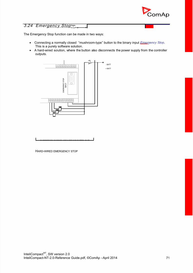
8/15/2019 InteliCompact NT 2.0 Reference Guide
http://slidepdf.com/reader/full/intelicompact-nt-20-reference-guide 71/287
InteliCompactNT
, SW version 2.0InteliCompact-NT-2.0-Reference Guide.pdf, ©ComAp – April 2014 71
3.24 Emergenc y Stop
The Emergency Stop function can be made in two ways:
Connecting a normally closed “mushroom-type” button to the binary input Emergency Stop.
This is a purely software solution. A hard-wired solution, where the button also disconnects the power supply from the controller
outputs.
E M E R G E N C Y S T O P
I N P U T
OUTPUTS
+ BATT
SUPPRESION DIODES ARE NOT INDICATED, BUT
REQUIRED!
- BATT
H ARD-WIRED EMERGENCY STOP

8/15/2019 InteliCompact NT 2.0 Reference Guide
http://slidepdf.com/reader/full/intelicompact-nt-20-reference-guide 72/287
InteliCompactNT
, SW version 2.0InteliCompact-NT-2.0-Reference Guide.pdf, ©ComAp – April 2014 72
4 Putting it into operation
4.1 Programming the conf igurat ion
The controller is delivered with a default configuration that should fit most standard applications.Nevertheless you may need to modify it because your application is different. Please refer to theLiteEdit manual or help file for information on using LiteEdit for changing the particular items of theconfiguration and writing the configuration to the controller.
CONFIGURATION WINDOW IN LITEEDIT
4.2 Programmin g the f irmw are
Although the controller is delivered with the latest firmware available at the moment of production, itmay be necessary to upgrade the firmware in future. The process of programming the firmwareinvolves the following steps:
1. First you need the requested firmware. Firmware of standard branch and major versions aredistributed and installed together with the LiteEdit installation package. Release versions andbranches are distributed as import packages that need to be imported into LiteEdit.
2. The latest installation and/or import packages are available for download at www.comap.cz. Please register to get access to the download page. Registration is free.
3. The import package is a file with the IWE extension. To perform the import, start LiteEdit, do
not open any connections, go to Options -> Import firmware and select the appropriate file.
4. Create an online connection to the controller and save the archive for backup purposes.
NOTE: It is not possible to update firmware when the connection is offline!
5. Go to the menu Controller -> Programming and cloning -> Programming, select the
appropriate firmware and press the OK button.6. The selected firmware will be programmed into your controller.

8/15/2019 InteliCompact NT 2.0 Reference Guide
http://slidepdf.com/reader/full/intelicompact-nt-20-reference-guide 73/287
InteliCompactNT
, SW version 2.0InteliCompact-NT-2.0-Reference Guide.pdf, ©ComAp – April 2014 73
NOTE: It is possible to program only firmware compatible with the currently attached controller. Otherfirmware is disabled and cannot be selected for programming.
CAUTION! The configuration reverts to the default after firmware has been programmed. You must re-program
the configuration if the default one is not appropriate for your application!
CAUTION! Also some setpoints may have incorrect values after new firmware was programmed. Please check allsetpoints after programming.
4.3 Programmin g a non -respo nsiv e con trol ler
If the controller does not contain valid firmware, new firmware cannot be programmed in the standardway. This situation can occur if the connection between the PC and the controller was interrupted e.g.during a previous firmware upgrade. In such a case the controller has a blank display and does not
communicate with the PC. The boot-jumper must be used to get valid firmware into the controller.
1. Disconnect the power supply from the controller, insert a communication module and close theboot-jumper.
BOOT-JUMPER ON IL-NT RS232
NOTE: See the communication modules chapter for information about boot-jumper position on othermodules.
2. Connect the proper communication cable between the controller and PC.3. Start LiteEdit and open an online connection according to the module used. Select controller
address 1. Wait until the bottom line of LiteEdit shows a red line with the text "DDE server:Error".
4. Go to the menu Controller -> Programming and cloning -> Programming, select the
appropriate firmware and press the OK button.5. Follow the instructions in the message that appears and finally press the OK button.
6. Another message will appear when programming is finished. Follow the instructions giventhere.

8/15/2019 InteliCompact NT 2.0 Reference Guide
http://slidepdf.com/reader/full/intelicompact-nt-20-reference-guide 74/287
InteliCompactNT
, SW version 2.0InteliCompact-NT-2.0-Reference Guide.pdf, ©ComAp – April 2014 74
4.5 Factory default con f igurat ion
4.5.1 SPtMSPtM only
BINARY INPUTS
NO. DESCRIPTION CONFIGURED FUNCTION
BI1 Generator circuit breaker feedback GCB Feedback
BI2 Mains circuit breaker feedback MCB Feedback
BI3 Remote start/stop Rem Start/Stop
BI4 Emergency stop button Emergency Stop
BI5 Access lock keyswitch Access Lock
BI6 Warning alarm None
BI7 Electrical trip alarm (BOC) None
BI8 Shutdown alarm None
BI9 Shutdown alarm None
BINARY OUTPUTS
NO. CONFIGURED FUNCTION
BO1 Starter
BO2 Fuel Solenoid
BO3 GCB Close/Open
BO4 MCB Close/Open
BO5 Prestart
BO6 Alarm
BO7 Horn
BO8 None
ANALOG INPUTS
NO. INPUT NAME CONFIGURED SENSOR
AI1 Oil pressure Sensor VDO 10 Bar, warning + shutdown alarm
AI2 Water temperature Sensor VDO 120 deg, warning + shutdown alarm
AI3 Fuel level Sensor VDO 180 Ohm, warning alarm
NOTE: A wiring diagram that corresponds to the factory default SPtM configuration is available in a separatechapter in the “Installation” section of this manual.

8/15/2019 InteliCompact NT 2.0 Reference Guide
http://slidepdf.com/reader/full/intelicompact-nt-20-reference-guide 75/287
InteliCompactNT
, SW version 2.0InteliCompact-NT-2.0-Reference Guide.pdf, ©ComAp – April 2014 75
4.5.2 MINT
MINT onlyBINARY INPUTS
NO. DESCRIPTION CONFIGURED FUNCTION
BI1 Generator circuit breaker feedback GCB Feedback
BI2 Mains circuit breaker feedback MCB Feedback
BI3 System start/stop Sys Start/Stop
BI4 Emergency stop button Emergency Stop
BI5 Access lock keyswitch Access Lock
BI6 Highest priority switch Top Priority
BI7 Large load preparation switch Min Run Power
BI8 Warning alarm None
BI9 Shutdown alarm None
BINARY OUTPUTS
NO. CONFIGURED FUNCTION
BO1 Starter
BO2 Fuel Solenoid
BO3 GCB Close/Open
BO4
BO5 Prestart
BO6 Alarm
BO7 Horn
BO8 SystReserve OK
ANALOG INPUTS
NO. INPUT NAME CONFIGURED SENSOR
AI1 Oil pressure Sensor VDO 10 Bar, warning + shutdown alarm
AI2 Water temperature Sensor VDO 120 deg, warning + shutdown alarm
AI3 Fuel level Sensor VDO 180 Ohm, warning alarm

8/15/2019 InteliCompact NT 2.0 Reference Guide
http://slidepdf.com/reader/full/intelicompact-nt-20-reference-guide 76/287
InteliCompactNT
, SW version 2.0InteliCompact-NT-2.0-Reference Guide.pdf, ©ComAp – April 2014 76
4.6 Step-by-step gu ide
In the following you will find several steps which you should carry out when you are putting a gen-setinto operation. It supposes that the switchboard wiring has been already checked.
NOTE: This guide is not a handbook for a beginner, but it is focused on things specific for ComAp controllersand expects sufficient knowledge and skills in the field of generating sets!
WARNING! Some parts of the generator, engine and switchboard may carry dangerous voltage which can causeinjury or death when touched!
WARNING! Rotating parts of the gen-set can catch hair or clothing and cause serious injury.
1. Disconnect the binary outputs from the controller before connecting the power supply. If you
have an SPtM application, be sure that the MCB and GCB are protected against accidentalswitching when you are working in the switchboard.
2. Check the controller configuration according to the wiring diagram of the switchboard. If theconfiguration has been modified, write it to the controller
3. Write all setpoints from the default archive and then go through them and readjust all of themif it is necessary. Pay special attention to nominal values, overspeed, gear teeth, fuel solenoidand CT ratio.
4. Check all settings regarding speed sensing and additional running information, especially ifyou do not use a pickup for speed sensing.
5. Adjust bias setpoints for the governor and AVRi output to the recommended levels and adjustall delays for generator protections to high values to have enough time for making adjustmentson a running gen-set.
6. Connect the binary outputs back.
7. Adjust all setpoints related to engine start and stabilization phase, then start the gen-set inMAN mode and then make fine readjustments.
8. Leave the gen-set running and adjust the governor and/or AVRi so that the gen-set will have aspeed and voltage near to the nominal values. If it is not possible to achieve this by turning thetrim on the AVRi and/or governor, you can also slightly change the bias setpoints.
NOTE: The bias setpoints must not be near the limits for the particular output, because the regulationloops need sufficient reserve of the output range on both sides to work correctly.
9. Adjust all generator and engine protections according to your needs including the delays.10. Adjust the setpoint Phase Window to 0. This adjustment will disable issuing of the GCB close
command during synchronization, but the synchronization itself will be performed normally forthe whole adjusted time.
11. Press the GCB button to start the synchronizing. Then, using a voltmeter connected directlyover the contactor, check if the synchroscope indication on the controller screen matches thevoltage. The voltage must be near to 0V when the synchroscope is in a 12 o'clock positionand near to 2*Unominal when it is in a 6 o'clock position. Check all three phases.

8/15/2019 InteliCompact NT 2.0 Reference Guide
http://slidepdf.com/reader/full/intelicompact-nt-20-reference-guide 77/287
InteliCompactNT
, SW version 2.0InteliCompact-NT-2.0-Reference Guide.pdf, ©ComAp – April 2014 77
V
GCB
O I
MIN MAX
OPEN
The voltmeter must show
minimum voltage in all phases
when the synchroscope is in 12
o’clock position
V
GCB
O I
MIN MAX
OPEN
The voltmeter must showmaximum voltage in all phases
when the synchroscope is in 6
o’clock position
12. Adjust the setpoint Phase Window back to your desired value (typically 3 –7°).13. Synchronize the gen-set with the mains or other gen-sets. Adjust the setpoints for voltage,
frequency and angle regulation loops to achieve fast and reliable synchronization.14. Adjust the setpoints for power, power factor, load-sharing and VARsharing loops.15. Check the rest of the setpoints and then save the archive to disk for backup purposes.
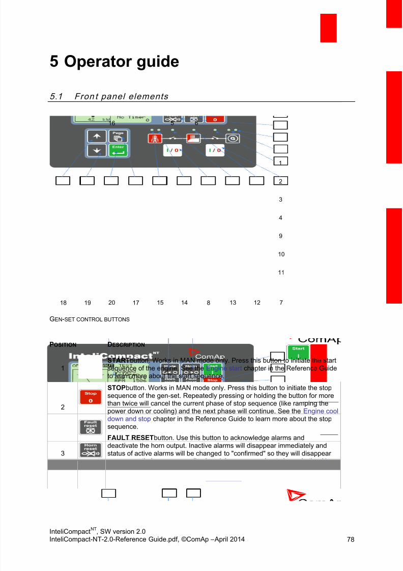
8/15/2019 InteliCompact NT 2.0 Reference Guide
http://slidepdf.com/reader/full/intelicompact-nt-20-reference-guide 78/287
InteliCompactNT
, SW version 2.0InteliCompact-NT-2.0-Reference Guide.pdf, ©ComAp – April 2014 78
5 Operator guide
5.1 Fron t panel elements
1
2
3
4
9
10
11
712138141517201918
6516
GEN-SET CONTROL BUTTONS
POSITION DESCRIPTION
1START button. Works in MAN mode only. Press this button to initiate the startsequence of the engine. See the Engine start chapter in the Reference Guideto learn more about the start sequence.
2
STOP button. Works in MAN mode only. Press this button to initiate the stopsequence of the gen-set. Repeatedly pressing or holding the button for morethan twice will cancel the current phase of stop sequence (like ramping thepower down or cooling) and the next phase will continue. See the Engine cooldown and stop chapter in the Reference Guide to learn more about the stopsequence.
3
FAULT RESET button. Use this button to acknowledge alarms anddeactivate the horn output. Inactive alarms will disappear immediately andstatus of active alarms will be changed to "confirmed" so they will disappearas soon as their causes are dismissed. Learn more about alarms in the Alarmmanagement chapter in the Reference Guide.
4HORN RESET button. Use this button to deactivate the horn output without
acknowledging the alarms.
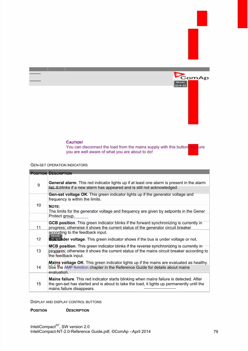
8/15/2019 InteliCompact NT 2.0 Reference Guide
http://slidepdf.com/reader/full/intelicompact-nt-20-reference-guide 79/287
InteliCompactNT
, SW version 2.0InteliCompact-NT-2.0-Reference Guide.pdf, ©ComAp – April 2014 79
5
MODE LEFT button. Use this button to change the mode. The button worksonly if the main screen with the indicator of the currently selected mode isdisplayed.
NOTE: This button will not work if the controller mode is forced by one of the binaryinputs listed in the Reference Guide in the Operating modes chapter.
6
MODE RIGHT button. Use this button to change the mode. The button worksonly if the main screen with the indicator of the currently selected mode isdisplayed.
NOTE: This button will not work if the controller mode is forced by one of the binaryinputs listed in the Reference Guide in the Operating modes chapter.
7
GCB button. Works in MAN and TEST modes only. Press this button to openor close the GCB or start synchronizing manually. Note that certain conditionsmust be fulfilled otherwise GCB closing (starting of synchronization) isblocked. See the Connecting to the load chapter in the Reference Guide for
details.
8
MCB button. Works in MAN and TEST modes only. Press this button to openor close the MCB or start the reverse synchronizing manually.
CAUTION! You can disconnect the load from the mains supply with this button! Be sureyou are well aware of what you are about to do!
GEN-SET OPERATION INDICATORS
POSITION DESCRIPTION
9 General alarm. This red indicator lights up if at least one alarm is present in the alarmlist. It blinks if a new alarm has appeared and is still not acknowledged.
10
Gen-set voltage OK. This green indicator lights up if the generator voltage andfrequency is within the limits.
NOTE: The limits for the generator voltage and frequency are given by setpoints in the GenerProtect group.
11GCB position. This green indicator blinks if the forward synchronizing is currently inprogress; otherwise it shows the current status of the generator circuit breakeraccording to the feedback input.
12 Bus under voltage. This green indicator shows if the bus is under voltage or not.
13MCB position. This green indicator blinks if the reverse synchronizing is currently inprogress; otherwise it shows the current status of the mains circuit breaker according tothe feedback input.
14Mains voltage OK. This green indicator lights up if the mains are evaluated as healthy.See the AMF function chapter in the Reference Guide for details about mainsevaluation.
15Mains failure. This red indicator starts blinking when mains failure is detected. Afterthe gen-set has started and is about to take the load, it lights up permanently until themains failure disappears.
DISPLAY AND DISPLAY CONTROL BUTTONS
POSITION DESCRIPTION

8/15/2019 InteliCompact NT 2.0 Reference Guide
http://slidepdf.com/reader/full/intelicompact-nt-20-reference-guide 80/287
InteliCompactNT
, SW version 2.0InteliCompact-NT-2.0-Reference Guide.pdf, ©ComAp – April 2014 80
16 Graphic B/W display, 128x64 pixels
17PAGE button. Use this button to switch across display pages. See the nextchapter for details about display pages and screens structure
18 UP button. Use this button to move up or increase value.
19 DOWN button. Use this button to move down or decrease value.
20ENTER button. Use this button to finish editing a setpoint or move right in thehistory page.
5.2 User interface modes
The user interface consists of two modes:
User mode allows the user to go through all screens with measurements and alarms. The
button does not work, i.e. setpoints and history pages are not accessible.
Engineer mode gives qualified personnel full access to all pages and screens.
See the chapter User interface mode selection to learn how to change the user interface mode.
5.3 Display screens and pages struc ture
The displayed information is structured into “pages” and “screens”. Use the button to switchover the pages.
1. The Measurement page consists of screens which display measured values like voltages,current, oil pressure, etc. and computed values such as gen-set power, statistic data and thealarm list on the last screen.
2. The Setpoints page contains all setpoints organized into groups and also a special group forentering the password.
3. The History log page shows the history log in order with the last record displayed first.
NOTE: The picture below shows the structure of displayed data. The contents of each particular screen maybe slightly different according to the firmware branch and version.

8/15/2019 InteliCompact NT 2.0 Reference Guide
http://slidepdf.com/reader/full/intelicompact-nt-20-reference-guide 81/287
InteliCompactNT
, SW version 2.0InteliCompact-NT-2.0-Reference Guide.pdf, ©ComAp – April 2014 81
P O
Time Date
16:00:00 16/11/2011
>15:00:00 16/11/2011
14:35:00 16/11/2011
19:20:00 14/11/2011
-1 Time Stamp
MEASUREMENT
SETPOINTS
HISTORY LOG
ENGINEER MODE ONLY
STRUCTURE OF THE DISPLAYED DATA

8/15/2019 InteliCompact NT 2.0 Reference Guide
http://slidepdf.com/reader/full/intelicompact-nt-20-reference-guide 82/287
InteliCompactNT
, SW version 2.0InteliCompact-NT-2.0-Reference Guide.pdf, ©ComAp – April 2014 82
5.4 View measured values
Press the button repeatedly until you see the main screen with the kW meter and mode
selector. Then press or to select the requested screen within the measurement page.
MODE SELECTOR
ACTIVE POWER
ENGINE STATUS
BREAKERS STATUS
POWER FACTOR
ENGINE SPEED
CURRENT PROCESS
TIMER
THE M AIN SCREEN
5.5 Setpoints – view and change
1. Press the button repeatedly until you see a screen with a list of setpoint groups. Then
select the desired group by pressing the or buttons and finally press the
button to continue to the selected group.2. Now you will see the list of setpoints which belong to the selected group together with their
current setting. Use the or buttons again to select the setpoint you want to
modify and press .3. The current value of the setpoint will appear in the right part under the setpoint name and you
can change it by pressing the or buttons. The rate of changing the value willaccelerate when the button is held down.
4. Press the button to confirm the change or to discard it and return to the list ofsetpoints of the selected group.
5. Continue by changing another setpoint or press to return to the list of groups.

8/15/2019 InteliCompact NT 2.0 Reference Guide
http://slidepdf.com/reader/full/intelicompact-nt-20-reference-guide 83/287
InteliCompactNT
, SW version 2.0InteliCompact-NT-2.0-Reference Guide.pdf, ©ComAp – April 2014 83
LIST OF GROUPS OF SETPOINTS
LIST OF SETPOINTS WITHIN SELECTED GROUP
EDITING A SETPOINT
5.6 Brow sing the history log
1. Press the button repeatedly until you see the main history log screen with the reasoncolumn and the latest record.
NOTE: The records are numbered in reverse order, i.e. the latest (newest) record is “0” and olderrecords have "-1", "-2", etc.
2. Use the button to move over columns within the selected record. Pressing it repeatedlywill move cyclically through the columns, i.e. after the last column the first one will bedisplayed.
3. Use the buttons and to move over the records.
4. Press the button to select another display page.
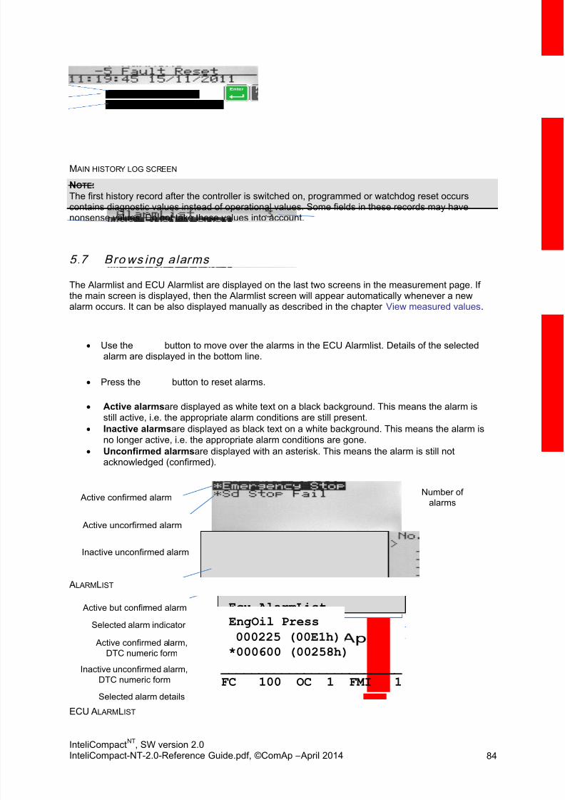
8/15/2019 InteliCompact NT 2.0 Reference Guide
http://slidepdf.com/reader/full/intelicompact-nt-20-reference-guide 84/287
InteliCompactNT
, SW version 2.0InteliCompact-NT-2.0-Reference Guide.pdf, ©ComAp – April 2014 84
M AIN HISTORY LOG SCREEN
NOTE: The first history record after the controller is switched on, programmed or watchdog reset occurscontains diagnostic values instead of operational values. Some fields in these records may havenonsense values. Do not take these values into account.
5.7 Brows ing alarms
The Alarmlist and ECU Alarmlist are displayed on the last two screens in the measurement page. Ifthe main screen is displayed, then the Alarmlist screen will appear automatically whenever a newalarm occurs. It can be also displayed manually as described in the chapter View measured values.
Use the button to move over the alarms in the ECU Alarmlist. Details of the selectedalarm are displayed in the bottom line.
Press the button to reset alarms.
Active alarms are displayed as white text on a black background. This means the alarm is
still active, i.e. the appropriate alarm conditions are still present. Inactive alarms are displayed as black text on a white background. This means the alarm is
no longer active, i.e. the appropriate alarm conditions are gone.
Unconfirmed alarms are displayed with an asterisk. This means the alarm is still notacknowledged (confirmed).
Inactive unconfirmed alarm
Active uncorfirmed alarm
Active confirmed alarmNumber of
alarms
ALARMLIST
Ecu AlarmList
>EngOil Press
000225 (00E1h)
*000600 (00258h)
________________________
FC 100 OC 1 FMI 1Inactive unconfirmed alarm,
DTC numeric form
Active confirmed alarm,
DTC numeric form
Active but confirmed alarm
EngOil Press
000225 (00E1h)Selected alarm indicator
Selected alarm details ECU ALARMLIST

8/15/2019 InteliCompact NT 2.0 Reference Guide
http://slidepdf.com/reader/full/intelicompact-nt-20-reference-guide 85/287
InteliCompactNT
, SW version 2.0InteliCompact-NT-2.0-Reference Guide.pdf, ©ComAp – April 2014 85
NOTE: The ECU AlarmList is visible only if an ECU is configured.
5.8 Entering the password
A password must be entered prior to adjusting setpoints that are password-protected. The password islocated in the first group of setpoints and the method to enter or change the password is similar tochanging setpoints as described in the setpoints chapter .
NOTE: It is possible to change only passwords of the same or lower level than the currently enteredpassword!
NOTE: Lost password? Display the information screen which contains the serial number and a passworddecode number as described in the chapter below. Write down both numbers and send a request toretrieve the password to your local distributor containing these two numbers. You can also save andsend an archive instead.
5.9 Contro l ler inform at ion screen
1. Press the button repeatedly until you will see the main controller screen with the modeselector and kW analog meter.
2. Hold down the button and simultaneously press the button to see the controllerinformation screen.
3. The information screen will disappear automatically after 5 seconds.
4. Press the button again within 5 to switch to the language selection screen.
5. Press the button again to switch to the user interface mode selection screen. Thisscreen also contains the serial number and password decode number.
6. Pressing the button next switches back to the information screen.
7. Press the button to get back to the controller main screen.

8/15/2019 InteliCompact NT 2.0 Reference Guide
http://slidepdf.com/reader/full/intelicompact-nt-20-reference-guide 86/287
InteliCompactNT
, SW version 2.0InteliCompact-NT-2.0-Reference Guide.pdf, ©ComAp – April 2014 86
+
+
1)
2)
1) Init Sreen is enabled
2) Init Screen is disabled
The information screen contains the following information:
Controller Name
Firmware identification string
Serial number of the controller
Firmware version, application version
Application type
Branch name

8/15/2019 InteliCompact NT 2.0 Reference Guide
http://slidepdf.com/reader/full/intelicompact-nt-20-reference-guide 87/287
InteliCompactNT
, SW version 2.0InteliCompact-NT-2.0-Reference Guide.pdf, ©ComAp – April 2014 87
5.10 Contro l ler language select ion
There are two languages available in the controller. The default languages are English and Chinese.The languages can be changed or modified during configuration in LiteEdit. See the LiteEdit documentation for details.
To switch the controller language:
1. Display the information screen as described above.
2. While the information screen is still displayed, press the button.
3. The Language menu will appear, use the or buttons to select the desiredlanguage.
4. Press to confirm the selection.
5.11 User interface mode select ion
To switch the User interface mode, follow these instructions:
1. Display the information screen as described above.
2. While the information screen is still displayed, press the button twice.
3. The user interface mode menu will appear, use the or buttons to select thedesired mode.
4. Press to confirm the selection.
5.12 Display con trast adjustm ent
1. Press the button repeatedly until you see the main controller screen with the modeselector and kW analog meter.
2. Hold down the button and simultaneously press or repeatedly to increase
or decrease the contrast.

8/15/2019 InteliCompact NT 2.0 Reference Guide
http://slidepdf.com/reader/full/intelicompact-nt-20-reference-guide 88/287
InteliCompactNT
, SW version 2.0InteliCompact-NT-2.0-Reference Guide.pdf, ©ComAp – April 2014 88
6 Function description
This chapter describes the most frequent situations in the gen-set control. Non-standard situations andcombinations with a low probability of occurrence are not described.
6.1 Island operat ion f lowchart
Gen-set ready
Start sequence
Start command: either pressing
START button in MAN mode or
automatic start in AUT or TEST
mode
StartFail alarm
Start not successful
Stabilization
sequenceGen. U/f alarm
Voltage and frequency
stabilization not successful
Continues automatically in AUT
mode or by pressing GCB
button in MAN mode
Connecting to the
load
(closing GCB)
Island operation (no
regulation is
performed)
Cooling and stop
sequence
stop sequence
Stop command: either
pressing STOP button in
MAN mode, or automatic
stop in AUT mode
Gen-set not
ready
Fault reset
Disconnecting load
(opening GCB)
GCB open command:
pressing GCB button in MAN
mode
Stop command?
Yes
No
StopFail alarm
Stop not successful
Stop sequence
continues

8/15/2019 InteliCompact NT 2.0 Reference Guide
http://slidepdf.com/reader/full/intelicompact-nt-20-reference-guide 89/287
InteliCompactNT
, SW version 2.0InteliCompact-NT-2.0-Reference Guide.pdf, ©ComAp – April 2014 89
6.2 Paral lel operat ion f low chart
Gen-set ready
Start sequence
Start command: either pressing
START button in MAN mode or
automatic start in AUT or TEST
mode
StartFail alarm
Start not successful
Stabilization
sequenceGen. U/f alarm
Voltage and frequency
stabilization not successful
Continues automatically in AUT
mode or by pressing GCB
button in MAN mode
Cooling and stop
sequence
stop sequence
Stop command:
either pressing
STOP button in MAN
mode, or automatic
stop in AUT mode
Gen-set not
ready
Fault reset
GCB open command:
pressing GCB button in
MAN mode
Stop command?
Yes
No
StopFail alarm
Stop not successful
Synchronization
Connecting to the
load
(closing the GCB)
Parallel operation
(kW/PF regulation
or kW/kVAr sharing)
SynchroTimeout
alarm
Synchronization not
successful
Soft loading
Soft unloading
Disconnecting load
(opening GCB)
Stop sequence
continues

8/15/2019 InteliCompact NT 2.0 Reference Guide
http://slidepdf.com/reader/full/intelicompact-nt-20-reference-guide 90/287
InteliCompactNT
, SW version 2.0InteliCompact-NT-2.0-Reference Guide.pdf, ©ComAp – April 2014 90
6.3 Operat ing modes
Selecting the operating mode is done through MODE buttons on the front panel or by changing theController mode setpoint (from the front panel or remotely).
NOTE:
If this setpoint is configured as password-protected, the correct password must be entered prior toattempting to change the mode.
NOTE: The mode cannot be changed if Access Lock input is active.
The following binary inputs can be used to force one respective operating mode independent of themode setpoint selection:
Remote OFF
Remote MAN
Remote AUT
Remote TEST
Rem TEST OnLd
If the respective input is active the controller will change the mode to the respective position accordingto the active input. If multiple inputs are active, the mode will be changed according to priorities of theinputs. The priorities match the order in the list above. If all inputs are deactivated, the mode will returnto the original position given by the setpoint.
6.3.1 OFF
The GCB will be opened and the engine will be immediately stopped in this mode without unloadingand cooling. After that the controller will stay in Not ready status and cannot be started any way. The
MCB is closed permanently (MCB Opens On = GENRUN) or is open or closed according to whetherthe mains are present or not (MCB Opens On = MAINSFAIL). No AMF function will be performed. Thebuttons MCB, GCB, START , STOP including the appropriate binary inputs for external buttons are notactive.
6.3.2 MAN
The engine can be started and stopped manually using the START and STOP buttons (or externalbuttons wired to the appropriate binary inputs) in MAN mode. When the engine is running, GCB canbe closed to a dead bus or synchronizing can be started by the GCB button. Also MCB can be closedand opened manually using the MCB button, regardless of whether the mains are present or not. Noauto start is performed. No reaction to the inputs Sys Start/Stop or Rem Start/Stop.
A loaded engine in MAN mode will perform Load sharing and VAR sharing , but will not take placewithin the power management.
NOTE: The breakers are internally locked to close two voltages against each other without synchronizing! Thecontroller will automatically recognize if the breaker can be just closed or must be synchronized.
CAUTION! The MCB can be opened manually in MAN mode. Accidental opening of the MCB will cause the object(load) to remain without power!!!
8/15/2019 InteliCompact NT 2.0 Reference Guide
http://slidepdf.com/reader/full/intelicompact-nt-20-reference-guide 91/287
InteliCompactNT
, SW version 2.0InteliCompact-NT-2.0-Reference Guide.pdf, ©ComAp – April 2014 91
6.3.3 AUT
The engine is started and stopped by the binary input Rem Start/Stop (SPtM), by the Load demandauto start function (SPtM) or by the Power management (MINT). The buttons MCB, GCB, START,STOP including the appropriate binary inputs for external buttons are not active. The full startsequence up to the moment when the engine is loaded is automatic as well as unloading and the stop
sequence.WARNING! If a red alarm is present and the gen-set is in AUT mode, it can start by itself after all red alarmsbecome inactive and are acknowledged!!! To avoid this situation, adjust the setpoint Reset to MAN tothe ENABLED position.
6.3.4 TESTSPtM only
The behaviour of the controller in TEST mode depends mainly on the setting of the ReturnFromTEST
setpoint.
Automatic return6.3.4.1
Setpoint ReturnFromTEST = ENABLED.
The gen-set will be started when the controller is put into TEST mode and will remain runningunloaded. If a mains failure occurs, the MCB will be opened and after Transfer Del the GCB will beclosed and the gen-set will supply the load. After the mains have recovered, the delayMainsReturnDel will count down and if it elapses and the mains are still ok, the controller willsynchronize back to the mains, transfer the load back to the mains (the maximum time that bothbreakers are closed is determined by the BreakerOverlap setpoint) and the gen-set will remainrunning unloaded again until the mode is changed.
Manual return6.3.4.2
Setpoint ReturnFromTEST = DISABLED.
The gen-set will be started when the controller is put to TEST mode and will remain running unloaded.If a mains failure occurs, the gen-set will take the load after it has started.
The load can be transferred to the gen-set also manually:
If the GCB button is pressed, the controller will synchronize to the mains, transfer the load tothe gen-set (the maximum time that both breakers are closed is determined by theBreakerOverlap setpoint) and then open the MCB.
If the MCB button is pressed, the controller will open the MCB, then wait for Transfer Del andfinally close the GCB.
When the load is supplied by the gen-set and the mains are healthy, pressing the MCB button will startreverse synchronizing and transfer the load back to the mains.
The gen-set remains running until the mode is changed.
Test with load6.3.4.3
If the binary input Rem TEST OnLd is activated, the controller is switched to TEST mode (i.e. the gen-set will be started as described above), but once started the controller will automatically either
synchronize to the mains, transfer the load to the gen-set (the maximum time that bothbreakers are closed is determined by the BreakerOverlap setpoint) and then open the MCB
or
will make a switchover, i.e. open the MCB, wait for Transfer Del and close the GCB.

8/15/2019 InteliCompact NT 2.0 Reference Guide
http://slidepdf.com/reader/full/intelicompact-nt-20-reference-guide 92/287
InteliCompactNT
, SW version 2.0InteliCompact-NT-2.0-Reference Guide.pdf, ©ComAp – April 2014 92
This depends on position of the binary input ForwSyncDisable. After the binary input Rem TEST OnLd has been deactivated, the controller goes back to the previous operation mode and its behaviourdepends on that. In most cases it will be AUT mode and the controller will either stay supplying theload if the mains have failed, or will transfer the load back to the mains.
NOTE: During the BreakerOverlap time, when both breakers are closed, the load is controlled either to the
constant Baseload level (if the MCB has to be opened) or to zero level (if the GCB has to be opened).
Periodic exercises6.3.4.4
The output from the Exercise timer 1 is internally connected to the Remote TEST binary input toenable periodic testing of the gen-set.
The controller must have AUT mode selected by the mode buttons and the other “mode forcing” binaryinputs must not be active to ensure proper function of the exercise.
NOTE: If a shutdown or other red alarm occurs while the load is supplied from the gen-set and the mains arehealthy, the load is switched back to the mains.
6.4 Eng ine start
6.4.1 Diesel engine
The setpoint Fuel Solenoid must be switched to the DIESEL position.
1. After the command for start is issued (pressing START button in MAN mode, auto startcondition is fulfilled in AUT mode or controller is switched to TEST mode), the output Prestart is energized for time period given by the setpoint Prestart Time.
2. After the prestart has elapsed, the output Fuel Solenoid is energized and 0.5 after that thestarter motor is activated by energizing the output Starter .
3. When one or more of following conditions are met, the prestart and starter of both outputs arede-energized:
The engine speed exceeds the value of Starting RPM , or
One of additional running indication signals becomes active.4. The controller remains in the Starting phase until the engine speed exceeds the value of
Starting RPM , after that it is considered as started and the Idle period will follow.5. The maximum duration that the starter motor is energized is determined by the setpoint
MaxCrank time. If the engine does not start within this period, the starter motor is de-energized and a pause with length determined by CrnkFail pause will follow. Prestart outputremains active during the pause. After the pause has elapsed, the next start attempt isexecuted. The number of start attempts is given by the setpoint Crank Attempts.
6. Once the engine is started, the Idle period follows. The binary output Idle/Nominal remainsinactive (as it was during the start). The idle period duration is adjusted by the setpoint IdleTime.
7. After the idle period has finished, the output Idle/Nominal is activated and the start-upsequence is finished. The stabilization phase follows.

8/15/2019 InteliCompact NT 2.0 Reference Guide
http://slidepdf.com/reader/full/intelicompact-nt-20-reference-guide 93/287
InteliCompactNT
, SW version 2.0InteliCompact-NT-2.0-Reference Guide.pdf, ©ComAp – April 2014 93
Starting RPM
reached?
Another “engine
running” symptom
present?
Starter
deactivated
MaxCrank time
elapsed?
Starter activated
Engine is started
Yes
Yes
Yes
No
No
No
Starter
deactivated
Poil > Starting Poil or
Ugen > 25 Unom in at least one
phase or
D+ input activated
Starting RPM
reached?
MaxCrank time
elapsed?
Yes
No
Engine is started
RPM Meas Fail alarm
Yes
Fuel solenoid = DIESEL
Fuel solenoid
activated
500ms
delay
Fuel solenoid
deactivated
Start fail alarmLast attempt?
Yes
Start pause
No

8/15/2019 InteliCompact NT 2.0 Reference Guide
http://slidepdf.com/reader/full/intelicompact-nt-20-reference-guide 94/287
InteliCompactNT
, SW version 2.0InteliCompact-NT-2.0-Reference Guide.pdf, ©ComAp – April 2014 94
6.4.2 Gas engine
The setpoint Fuel Solenoid must be switched to the GAS position.
1. After the command for start is issued (pressing START button in MAN mode, auto startcondition is fulfilled in AUT mode or controller is switched to TEST mode), the output Prestart
is energized for time period given by the setpoint Prestart Time. 2. After the prestart has elapsed, the starter motor is activated by energizing the output Starter . 3. When the engine speed exceeds 30RPM, the outputs Fuel Solenoid and Ignition are
energized.4. When the engine speed exceeds value of Starting RPM , the starter motor is de-energized, the
engine is considered as started and the Idle period will follow.
CAUTION! Additional running indication signals are not evaluated during the start of a gas engine. ThePickup must be used in any case!
5. The maximum duration the starter motor is energized is determined by the setpoint MaxCrankTime. If the engine does not start within this period, the starter motor and fuel solenoid are de-
energized and a pause with a length determined by CrnkFail Pause will follow. Prestart outputand ignition remain active during the pause. After the pause has elapsed, the next startattempt is executed. The number of start attempts is given by the setpoint Crank Attempts.
6. Once the engine is started, the Idle period follows. The binary output Idle/Nominal remainsinactive (as it was during the start). The idle period duration is adjusted by the setpoint IdleTime.
7. After the idle period has finished, the output Idle/Nominal is activated and the start-up
sequence is finished. The stabilization phase follows.

8/15/2019 InteliCompact NT 2.0 Reference Guide
http://slidepdf.com/reader/full/intelicompact-nt-20-reference-guide 95/287
InteliCompactNT
, SW version 2.0InteliCompact-NT-2.0-Reference Guide.pdf, ©ComAp – April 2014 95
Starting RPM
reached?
MaxCrank time
elapsed?
Starter activated
Engine is started
Start fail alarm
Yes
Yes
No
No
Starter
deactivated
Starter, Fuel
solenoid, Ingition
deactivated
Fuel solenoid = GAS
Fuel solenoid
and Ignition
activated
30 RPM reached?
Last attempt?
Yes
Start pause

8/15/2019 InteliCompact NT 2.0 Reference Guide
http://slidepdf.com/reader/full/intelicompact-nt-20-reference-guide 96/287
InteliCompactNT
, SW version 2.0InteliCompact-NT-2.0-Reference Guide.pdf, ©ComAp – April 2014 96
NOTE: The starting sequence will be interrupted at any time if a stop command comes.NOTE: The Underspeed protection starts to be evaluated 5 after the engine has been started (according topoint 4).
NOTE: When the engine is started (according to point 4) the delay given by the setpoint ProtectHoldOff willcount down. After it has elapsed, the protections configured as engine running only will start to beevaluated.
Continue to the stabilization phase.
6.5 Stabil ization
When the start-up sequence is finished, the gen-set goes into the stabilization phase. There are twotimers (setpoints) in this phase:
1. Min Stab Time starts to count down just after the idle period has finished. Generator voltageand frequency are not checked (respective protections are not evaluated) and the GCBcannot be closed even if the generator voltage and frequency are within limits.
2. Max Stab Time starts to count down just after the idle period has finished. Generator voltageand frequency are not checked (respective protections are not evaluated) but, opposite to theprevious timer, the GCB can be closed (or synchronizing started) if generator voltage and
frequency are within limits.
In situations where the GCB is closed automatically (AUT, TEST modes), the closing of GCB orstarting of synchronization will occur in the first moment when the generator voltage and frequency will
get into limits and the Min Stab Time has already elapsed.
In the event that the generator voltage or frequency are not within limits within the Max Stab Time period, the appropriate protection(s) will be activated and the gen-set will be cooled down andstopped.
NOTE: The limits for the generator voltage and frequency are given by setpoints in the Gener protect group.
NOTE: The value of the Min Stab Time setpoint must be lower than the value of Max Stab Time setpoint.
Continue to the connecting to the load phase.
6.6 Connect ing to the load
When the stabilization phase is finished, the gen-set can be connected to the load.
The command for connecting the gen-set to the load is issued either automatically (AUT, TESTmodes) or manually by pressing the GCB button. The following conditions must be valid:
The gen-set is running and the Min Stab Time timer has elapsed.
The gen-set voltage and frequency are within limits.

8/15/2019 InteliCompact NT 2.0 Reference Guide
http://slidepdf.com/reader/full/intelicompact-nt-20-reference-guide 97/287
InteliCompactNT
, SW version 2.0InteliCompact-NT-2.0-Reference Guide.pdf, ©ComAp – April 2014 97
NOTE: The governor and AVR must be adjusted properly to achieve these limits as the controller does notperform any regulation and the regulation outputs have constant values given by the AVRi Bias andSpeed Gov Bias setpoints.
There are two ways to connect the gen-set to the load (bus bar). This depends on the state of MCB
feedback and on the measured mains/bus voltage.
6.6.1 Connecting to dead bus
SPtM: if the MCB is open, the bus bar is considered as voltage-free and the GCB is closed withoutsynchronizing.
MINT: the measured bus voltage is also taken in account and it must be below 2% of the nominal busvoltage together with the open MCB to close the GCB without synchronizing.
NOTE: If the group of gen-sets is activated and multiple gen-sets have to start simultaneously and connect tothe empty bus bar, there is an internal logic to prevent closing of more GCBs to the bus bar at the
same moment without synchronizing. One of the gen-sets will close the GCB, the others will wait andthen they will synchronize to the first one.
NOTE:There also is a protection of “Bus power loss sensing”. The “Bus Measure Error” is detected in MINTapplication when the voltage on the controller’s bus terminals is out of limits 20 seconds after:
a) GCB (own) was closed in MAN or AUT modeb) MCB (feedback) was closed in AUT modec) Any other GCB in power management group (on CAN bus) was closed.
The alarm is activated after 20s. However, the GCB (own) closing is blocked immediately for safetyreasons.
This protection can avoid e.g. potential direct closing of GCB while the controller’s bus conductor s areunintentionally unplugged from the terminals.
6.6.2 Synchronizing
SPtM: If the MCB is closed, the bus bar is considered to have identical voltage as measured on themains. If the mains voltage/frequency is within limits, the gen-set is first synchronized with the mainsand then the GCB is closed.
MINT: If the measured bus voltage is within limits, the gen-set is first synchronized with the bus and
then the GCB is closed.
The synchronizing consists of voltage matching and frequency/angle matching. The maximumduration of synchronizing is given by the setpoint Sync Timeout . If the synchronizing is not successfulwithin this period of time, the Sync Timeout alarm will be issued.
NOTE: The synchronization will be interrupted automatically if any of the necessary conditions disappearduring the synchronization process.
When the controller starts to synchronize (the event will change to “Synchro”) and the Main Measuringscreen is displayed, it will be automatically change to the Synchroscope screen for the entire durationof synchronization. After synchronization the Synchroscope screen is automatically changed back tothe Main Measuring screen.
8/15/2019 InteliCompact NT 2.0 Reference Guide
http://slidepdf.com/reader/full/intelicompact-nt-20-reference-guide 98/287
InteliCompactNT
, SW version 2.0InteliCompact-NT-2.0-Reference Guide.pdf, ©ComAp – April 2014 98
NOTE:It is also possible to change screens manually (arrows Up and Down) after displaying theSynchroscope screen. In this case there is no automatic return to the Main Measuring screen aftersynchronization is finished.
Voltage matching6.6.2.1
The gen-set voltage is regulated to match the mains/bus voltage with tolerance given by the setpointVoltage Window . The regulation is adjusted by the setpoints Voltage Gain and Voltage Int .
Frequency/angle matching6.6.2.2
The gen-set frequency is regulated to match the mains/bus frequency first. The frequency regulationloop is active (setpoints Freq Gain and Freq Int ). Once the frequency is matched, the regulation loop isswitched to match the angle (setpoint Angle Gain). When the angle is matched with tolerance +/-Phase Window for a time given by the setpoint Dwell Time and the voltage is matched too, then theGCB is closed.
NOTE: The GCB close command will be not issued if the Phase Window setpoint is set to 0. Synchronizing
will continue until the Sync Timeout alarm occurs or the GCB is closed externally.
NOTE: The matching loops will continue to run even if the GCB close command has been already issued untilthe controller receives GCB feedback or a GCB fail alarm occurs. After the feedback has beenreceived, the control loops are switched to load and power factor loops or load and power factorsharing respectively.
6.7 Paral lel to mains operat ion – SPtM
SPtM only
After the gen-set has been synchronized to the mains, the parallel to mains operation follows. Itconsists of the following phases:
6.7.1 Ramping the power up
The first phase of the PTM operation is ramping the gen-set up to the requested power level. Thespeed of the ramp is given by the setpoint Load Ramp. The setpoint adjusts the ramp time for achange from 0% to 100% of nominal power.
6.7.2 Load control
The load is maintained at the constant level given by the setpoint Baseload . Regulation adjustmentsetpoints are available in the Sync/load control group.
NOTE: In every moment when the requested load (e.g. baseload setpoint) changes, the ramp described in thechapter above will also take place.
6.7.3 Power factor control
The power factor is regulated to a constant value given by the setpoint Base PF . PF regulation loop isactive. Regulation adjustment setpoints are available in the Volt/PF control group.

8/15/2019 InteliCompact NT 2.0 Reference Guide
http://slidepdf.com/reader/full/intelicompact-nt-20-reference-guide 99/287
InteliCompactNT
, SW version 2.0InteliCompact-NT-2.0-Reference Guide.pdf, ©ComAp – April 2014 99
6.7.4 Object load dependent auto start
The gen-set can start and stop automatically according to the object load. To enable this function, thesetpoint PeakAutS/S del must not be set to 0 (OFF). An automatic start will occur if the object exceedsthe limit given by the setpoint PeakLevelStart and remains exceeded for a period longer thanPeakAutS/S del . If the object load drops below PeakLevelStop, the gen-set will be stopped with the
same delay as during start. The gen-set load is controlled according to the selected mode (seeabove).
NOTE: The gen-set will continue to run if the binary input Rem Start/Stop is active.
6.7.5 Ramping the power down
When a stop command is received – e.g. the binary input Sys Start/Stop is deactivated or the STOPbutton is pressed – the gen-set load is ramped down before opening the GCB. The ramp speed isgiven by the setpoint Load Ramp, the end level is given by GCB Open Level and the timeout forfinishing the ramping without reaching the open level is given by GCB open Del .
When the GCB button is pressed, the gen-set load is ramped down before opening the GCB as well.But after the GCB has been opened, the gen-set remains running until a stop command comes or theGCB is pressed again to reclose the GCB.
Continue to the cool down and stop phase.
6.7.6 Peak load shaving
The gen-set can start and stop automatically according to the object load. An automatic start will occurif the object load exceeds a given upper limit (PeakLevelStart ) and remains exceeded for a givenperiod of time (PeakAutS/S Del ). If the object load drops below a given lower limit (PeakLevelStop),the gen-set will be stopped with the same delay period experienced during start.
2:00 4:00 6:00 8:00 10:00 12:00 14:00 16:00 18:00 20:00 22:00 24:00 Time [h]
L o a d [ k W ]
Start Start
Stop Stop
Peak Level Start
Peak Level Stop
Covered by
Mains
Covered by
Gen-set
NOTE:For this function it is necessary to use the IC-NT-CT-BIO7 extension module for measurement ofMains 1Ph current. The Im/EF CT Ratio parameter must be set up according to the current measuringtransformer and the Im/EF input parameter must be set to Mains.
6.7.7 Export Limit
If Export Limit function is enabled, the value of power which is covered by mains is given by value of
setpoint Export kW . E.g. if 100 kW has to be covered always by mains the Export kW parameter is setto -100 kW. The rest, all peaks, are then covered by gen-set or by group of gen-sets.

8/15/2019 InteliCompact NT 2.0 Reference Guide
http://slidepdf.com/reader/full/intelicompact-nt-20-reference-guide 100/287
InteliCompactNT
, SW version 2.0InteliCompact-NT-2.0-Reference Guide.pdf, ©ComAp – April 2014 100
NOTE:If the Export kW setpoint is negative, it actually means import. This function can be used to protect thesystem from unwanted export. You may set maximum export value or you can set it negative to keepsome import even in cases that there are abrupt load changes.
Required Power from gen-set
Power Consumption of the Load
Power imported from Mains
0
0
0
Import
Controller decreases the required power from
gen-set to maintain the constant level of Import
from Mains as the load consumption decreases
No power is taken from the gen-set and the load
consumption still goes down, so the Import fromMains cannot be maintained on the constant
level and it is starting to lower as well
PRINCIPLE OF THE EXPORT LIMIT FUNCTION – IMPORT

8/15/2019 InteliCompact NT 2.0 Reference Guide
http://slidepdf.com/reader/full/intelicompact-nt-20-reference-guide 101/287
InteliCompactNT
, SW version 2.0InteliCompact-NT-2.0-Reference Guide.pdf, ©ComAp – April 2014 101
Required Power from gen-set
Power Consumption of the Load
Power exported to Mains
0
0
0
Export
Load consumption goes to 0
Gen-set is still producing power to fulfill
the export requirement to the Mains
Negative value of
Import is Export
Gen-set is only exporting
below this level
PRINCIPLE OF THE EXPORT LIMIT FUNCTION – EXPORT

8/15/2019 InteliCompact NT 2.0 Reference Guide
http://slidepdf.com/reader/full/intelicompact-nt-20-reference-guide 102/287
InteliCompactNT
, SW version 2.0InteliCompact-NT-2.0-Reference Guide.pdf, ©ComAp – April 2014 102
6.8 Paral lel to mains operat ion – MINT
MINT only
If the MCB is closed (MCB feedback is present) and the gen-set has been synchronized to the busbar, the parallel to mains operation will follow. It consists of the following phases:
6.8.1 Ramping the power up
The first phase of the PTM operation is the ramping of the gen-set up to the desired power levelderived from the system baseload or up to the load given by load sharing with other gen-setsconnected to the bus bar. The speed of the ramp is given by the setpoint Load Ramp. The setpointadjusts the ramp time for a change from 0% to 100% of nominal power.
6.8.2 Load control modes
There are two load control modes – system baseload and load sharing – which are selected by thesetpoint #SysLdCtrl PtM . See the setpoint description for more information. If system baseload mode
is selected, the Load regulation loop is active to maintain the load at the requested level which isderived from the system baseload. Each running gen-set takes a relatively equal part of the systembaseload.
In load sharing mode, the loop LS (load sharing) is active to maintain the load at the same relativelevel as the other loaded gen-sets in the group. The behaviour in this case is identical to multipleisland mode.
NOTE: The process of determining which gen-sets shall run is described in the power management chapter.
6.8.3 Power factor control
In system baseload mode the power factor is regulated to a constant value given by the setpoint#SysPwrFactor . The PF regulation loop is active. In load sharing mode, also power factor sharing isactive to keep the power factor of all loaded gen-sets at an equal level. Regulation adjustmentsetpoints are available in the Volt/PF control group.
6.8.4 Ramping the power down
When a stop command is received – e.g. power management or binary input Sys Start/Stop isdeactivated or the STOP button is pressed – the gen-set load is ramped down before opening theGCB. The ramp speed is given by the setpoint Load Ramp, the end level is given by GCB Open Level and the timeout for finishing the ramping without reaching the open level is given by GCB Open Del .
When the GCB button is pressed, the gen-set load is ramped down before opening the GCB as well.But after the GCB has been opened, the gen-set remains running until a stop command comes or theGCB is pressed again to reclose the GCB.
Continue to the cool down and stop phase.
6.9 Island operation – SPtM
SPtM only
A situation where the MCB is open and the load is supplied from the gen-set is called Island operation.
This situation will occur in the following cases:
1. The GCB has been closed to a dead bus bar, or2. The gen-set was running parallel to the mains and the MCB has been opened.

8/15/2019 InteliCompact NT 2.0 Reference Guide
http://slidepdf.com/reader/full/intelicompact-nt-20-reference-guide 103/287
InteliCompactNT
, SW version 2.0InteliCompact-NT-2.0-Reference Guide.pdf, ©ComAp – April 2014 103
Neither voltage nor a frequency regulation loop is active. Keeping voltage and frequency at ratedvalues is the task of AVR and the governor.
When a stop command is received – e.g. the binary input Sys Start/Stop is deactivated or the STOPbutton is pressed – the GCB will be opened and the gen-set will go to cool down phase.
NOTE:
When using the GCB button in MAN mode, the gen-set will not go to cool down and stop.
6.9.1 Island to PtM transfersSPtM only
If the mains are OK, the gen-set can be transferred back to the parallel to mains operation. Thetransfer can be done as no-break transfer (Reverse synchronizing ) or break transfer (Changeover ).Which of these kinds will be performed depends on the binary input RevSyncDisable.
In AUT mode or TEST mode with automatic return, the reverse synchronizing or changeover is startedautomatically after the mains have been restored and remain healthy for a period given by the setpointMainsReturnDel . Reverse synchronizing can be started manually by pressing MCB button in MANmode.
Reverse synchronizing6.9.1.1
The reverse synchronizing process is identical to Forward synchronizing, but MCB is closed instead ofGCB. In the event that the reverse synchronizing is not successful, RevSyncTimeout alarm is issuedand the gen-set continues in island operation. After the alarm has been reset, the gen-set can try toperform reverse synchronizing again.
Changeover6.9.1.2
The changeover is performed if the reverse synchronizing is disabled with the RevSyncDisable binaryinput.
The GCB is opened first and after a time period of Transfer Del the MCB is closed.
6.10 Island operation – MINT
MINT only
This chapter describes the situation where multiple gen-sets are running parallel to each other but notwith mains. This situation will occur either when:
1. The common bus bar is dead due to opened MCB or there are no mains at all and the groupof gen-sets has been activated, or
2. The group was running parallel to mains and the MCB has been opened.
NOTE: The controller in MINT application does not control the MCB! Only the MCB position is evaluated fromthe binary input MCB Feedback and the position is the basic source of information for switchingbetween island and parallel to mains operation.
If the bus bar is empty, the first gen-set will close its GCB without synchronizing. Following gen-setswill synchronize to the already energized bus bar. In the event that multiple gen-sets startsimultaneously and the bus bar is empty, the system will prevent closing of multiple GCBs to the busbar without synchronizing. Instead of this, one of the gen-sets will close the GCB and energize the busbar and the others will wait and then synchronize to the bus bar.
When a stop command is received, e.g. from the power management or binary input Sys Start/Stop is
deactivated or the STOP button is pressed, the GCB will be opened and the gen-set will go to cooldown phase.

8/15/2019 InteliCompact NT 2.0 Reference Guide
http://slidepdf.com/reader/full/intelicompact-nt-20-reference-guide 104/287
InteliCompactNT
, SW version 2.0InteliCompact-NT-2.0-Reference Guide.pdf, ©ComAp – April 2014 104
NOTE: Using the GCB button in MAN mode the gen-set will not go to cool down and stop.
Continue to the cool down and stop phase.
6.11 Power management
MINT only
The power management is related to MINT application only. Power management is the process ofautomatic starts and stops of gen-sets within the group, depending on current load, state of the gen-sets and other conditions.
6.11.1 The concept
The power management is based on the load of the gen-sets, i.e. next gen-set will start when the loadof the group raises above certain level. A next gen-set will stop, when the load drops down below a
certain level. The process of determining of starts and stops is done in each controller; there is no"master" in the system. Each of the controllers can be switched off without influencing the completesystem (except the situation when the respective gen-set will be not available...)
The load of the group is evaluated as so called reserve. The reserve is calculated as differencebetween actual and nominal load of running gen-sets. The reserve can be calculated as absolute (inkW) or relative (in %). Use the setpoint #PowerMgmt Mode to set the calculation method.
NOTE: Power management based on relative reserves perfectly fits for applications, where the load portionsconnected to the group at once are much lower than the gen-set capacity. This mode helps to achievemaximal lifetime of the gen-sets, as they can be operated within optimal load range. The maximalsize of the load connected at once depends on number of actually working gen-sets. The more
gen-sets are connected to the busbar, the bigger a load portion can be connected at once.
Power management based on absolute reserves can be successfully used also for cases where theload portions are similar to the gen-set capacity or even bigger. The goal of the absolute reserve modeis that the system provides always the same reserve power capacity independent of how manygen-sets are currently running and this why this mode perfectly fits for industrial plants with largeloads.
There is a new way of power management implemented (Efficient mode; LDS) since version IC-NT2.0. Basic principles and functions are explained in the chapter below.
6.11.2 Basics
The setpoint Pwr Management enables and disables the gen-set to be active within the powermanagement of the group and make automatic load demand start/stop or swap. If the powermanagement is disabled, the gen-set will run or not depending only on the binary input SysStart/Stop and the start and stop will not depend on the load of the group.
The binary input Sys Start/Stop activates and deactivates the gen-set. If the input is not active,the gen-set will stop with delay #SysAMFstopDel after the input has been deactivated and will
not start again. It can be started in MAN mode only. When the input is activated again, thedelay #SysAMFstrtDel will start to count down and after that the gen-set is activated and canstart due to power management.
NOTE: The gen-set will take part of the power management (= will be active) only if the controller is in AUT
mode!

8/15/2019 InteliCompact NT 2.0 Reference Guide
http://slidepdf.com/reader/full/intelicompact-nt-20-reference-guide 105/287
InteliCompactNT
, SW version 2.0InteliCompact-NT-2.0-Reference Guide.pdf, ©ComAp – April 2014 105
NOTE: The gen-set performs load and VAR sharing whenever it is connected to the busbar i.e. it isindependent on whether the controller is in AUT or MAN mode or whether the power management isactive or not.
6.11.3 Reserves, minimal running power
The value ( ∑ ∑ ) [%] is called relative reserve. It is the difference between the
actual relative load and 100%.
The value ∑ ∑ [kW] is called absolute reserve. It is the difference between theactual load of the group and the nominal capacity of currently loaded gen-sets.
Running ActPwr = the sum of the actual load of all active gen-sets within the group, thatare connected to the bus. In parallel to mains operation and baseload mode thebaseload level is used in the equation instead of the actual gen-sets load.
Running NomPwr = the sum of the nominal power of all active gen-sets within thegroup, that are connected to the bus.
If the current system reserve drops below the adjusted reserve for start, the delay#NextStrt Del will start to count down on the gen-sets, which have decided to start. If thereserve remains under the limit for the entire countdown period, the gen-set(s) will start.
If the system reserve drops below zero (i.e. the system is overloaded), the delay#OverldNext Del will start to count down on the gen-sets, which have decided to start. If thereserve remains under the limit for the whole countdown period, the gen-set(s) will start.
If the system reserve goes above over the adjusted reserve for stop, the delay#NextStopDel will start to count down on the gen-sets, which have decided to stop. If thereserve still remains over the limit, the gen-sets will stop.
There are two pairs of setpoints for adjusting reserves for start and stop. Normally the pair#LoadResStrt 1 and #LoadResStop 1 is active. By the binary input Load Reserve 2 thesecond pair #LoadResStrt 2 and #LoadResStop 2 is activated.
With adjusting nonzero value to the setpoint #Min Run Power and activating the function bybinary input Min Run Power => based on the nominal power, the gen-sets needed for
equalizing the actual MinRunPower requirement are started (or kept running even if stopreserve is fulfilled). Note, that LBI’s Min Run Power needs to be activated on all gen-sets inthe same time.
6.11.4 Priorities
The priority of the gen-set within the group is determined by the setpoint Priority . A lowernumber represents “higher ” priority, i.e. a gen-set with a lower number will start before anotherone with higher number.
For Load Demand Star/Stop regime:- If the binary input Top Priority is active, the gen-set gets highest priority (0)
independent of the setpoint setting.- If more than one gen-set have the same priority, they will act as “one big” gen-set.
For Load Demand Swap regime and Run Hour Equalisation: - Priorities are managen automatically by the controller and value written in the setpoint
is ignored- Binary input Top Priority has no function

8/15/2019 InteliCompact NT 2.0 Reference Guide
http://slidepdf.com/reader/full/intelicompact-nt-20-reference-guide 106/287
InteliCompactNT
, SW version 2.0InteliCompact-NT-2.0-Reference Guide.pdf, ©ComAp – April 2014 106
6.11.5 Load Demand Start/Stop
The controller will decide to start the gen-set at the moment when the reserve has droppedbelow the reserve for start and the gen-sets with higher priorities (lower priority numbers), thatare available for power management, do not have enough capacity to get the reserve backover the start level or cannot fulfil the adjusted minimal running power
The controller will decide to stop the gen-set at the moment when the reserve has increasedover the reserve for stop and the gen-sets with higher priorities (lower priority numbers), thatare available for power management, have enough capacity to keep the reserve over the startlevel and also can fulfil the adjusted minimal running power
NOTE: When evaluating the stop condition, the controller computes actual reserve without taking in accountits own nominal power, i.e. it evaluates how the reserve will be if the respective gen-set stops.
Load
[kW]
P n o m G e n - s e t 1
P r i o r i t y 1
P n o m G e n - s e t 2
P r i o r i t y 2
P n o m G e n - s e t 3
P r i o r i t y 3
t
LoadRes Strt [kW]
LoadRes Strt [kW]
LoadRes Stop [kW]
LoadRes Stop [kW]
LoadRes Stop [kW]
Sys Start/Stop
Gen-set 1
running
Gen-set 2
running
Gen-set 3
running
#SysAMFstrtDel
#NextStrt Del
#NextStrt Del
t < #NextStrt Del
#NextStop Del
#NextStop Del
#SysAMFstopDel
Pg_nom_1 [kW]
Pg_nom_1+Pg_nom_2 [kW]
Pg_nom_1+Pg_nom_2+Pg_nom_3 [kW]
POWER MANAGEMENT WITH ABSOLUTE RESERVES
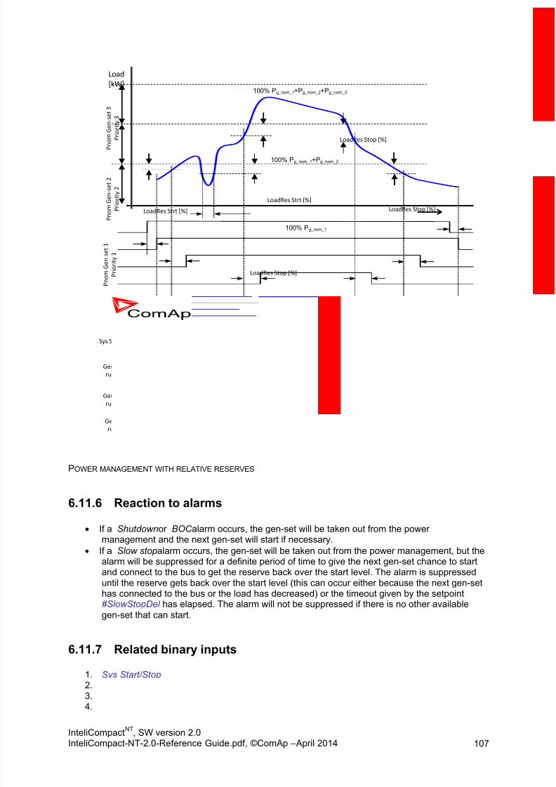
8/15/2019 InteliCompact NT 2.0 Reference Guide
http://slidepdf.com/reader/full/intelicompact-nt-20-reference-guide 107/287
InteliCompactNT
, SW version 2.0InteliCompact-NT-2.0-Reference Guide.pdf, ©ComAp – April 2014 107
Load
[kW]
P n o m
G e n - s e t 1
P
r i o r i t y 1
P n o m G e n - s e t 2
P r i o r i t y 2
P n o m
G e n - s e t 3
P r i o r i t y 3
t
LoadRes Strt [%]
LoadRes Strt [%]
LoadRes Stop [%]
LoadRes Stop [%]
LoadRes Stop [%]
Sys Start/Stop
Gen-set 1
running
Gen-set 2
running
Gen-set 3
running
#SysAMFstrtDel
#NextStrt Del
#NextStrt Del
t < #NextStrt Del
#NextStop Del
#NextStop Del
#SysAMFstopDel
100% Pg_nom_1
100% Pg_nom_1+Pg_nom_2
100% Pg_nom_1+Pg_nom_2+Pg_nom_3
POWER MANAGEMENT WITH RELATIVE RESERVES
6.11.6 Reaction to alarms
If a Shutdown or BOC alarm occurs, the gen-set will be taken out from the powermanagement and the next gen-set will start if necessary.
If a Slow stop alarm occurs, the gen-set will be taken out from the power management, but thealarm will be suppressed for a definite period of time to give the next gen-set chance to startand connect to the bus to get the reserve back over the start level. The alarm is suppresseduntil the reserve gets back over the start level (this can occur either because the next gen-sethas connected to the bus or the load has decreased) or the timeout given by the setpoint#SlowStopDel has elapsed. The alarm will not be suppressed if there is no other available
gen-set that can start.
6.11.7 Related binary inputs
1. Sys Start/Stop
2. Load Reserve 2 3. Top Priority 4. Min Run Power

8/15/2019 InteliCompact NT 2.0 Reference Guide
http://slidepdf.com/reader/full/intelicompact-nt-20-reference-guide 108/287
InteliCompactNT
, SW version 2.0InteliCompact-NT-2.0-Reference Guide.pdf, ©ComAp – April 2014 108
6.11.8 Related binary outputs
1. System Ready 2. SystReserve OK 3. EnginesSwapped
6.11.9 Load Demand Swap
There is a new way of power management implemented (Efficient mode; LDS) since version IC-NT2.0. Basic principles and functions are explained in the chapter below.
CAUTION! MainsCompact
NT is not supported for use with IC-NT 2.0+ firmware. Please use IC-NT 1.4.5 instead.
Principles of the Load Demand Swap (#PriorAutoSwap = EFFICENT)
To evaluate, which gen-set will start as next, two situations need to be distinguished:
1) First start (activation of Sys Start/Stop binary input)2) Already running group of gen-sets
Add1) master controller (the one with the lowest CAN address) makes the calculation and sorts allthe gen-sets in the group based on their nominal power and running hours from the biggest tosmallest. Gen-set which fulfils following formula will be selected:
Pnom < #LoadResStrt 1
Where Pnom is the nominal power of the selected gen-set
If two gen-sets with the same nominal power are available, the one with least amount of run hours is
started.
Add2)
a) Master controller on the fly sorts available gen-sets based on their nominal power from thebiggest to smallest
b) If two or more gen-sets with the same nominal power are available, least amount of run hours ispreferred (lower run hours = higher priority)
c) Selection of which gen-set has to start next is from the bottom of the list to the top (small gen-set starts first) following formula:
Pnom > Load demand + #LoadResStrt 1
Where Pnom is the nominal power of selected gen-set
d) If load demand is higher than nominal power of the biggest gen-set, this one is fixed and thewhole process repeats from c).
e) For gen-sets with the same nominal power also run hour equalization will be performed.

8/15/2019 InteliCompact NT 2.0 Reference Guide
http://slidepdf.com/reader/full/intelicompact-nt-20-reference-guide 109/287
InteliCompactNT
, SW version 2.0InteliCompact-NT-2.0-Reference Guide.pdf, ©ComAp – April 2014 109
Example:
#PowerMgmtMode = ABS#LoadResStrt 1 = 20kW#LoadResStop 1 = 30kW
Load Demand Swap related setpoints and values:
6.11.10 Related binary inputs
1. Sys Start/Stop 2. Load Reserve 2 3. Min Run Power
6.11.11 Related binary outputs
1. System Ready 2. SystReserve OK 3. EnginesSwapped
6.11.12 “How to” examples: How to set EFFICENT mode (Load demand swap function); available since IC-NT 2.0
In Pwr management setpoint group:
make sure Power Management is enabled (Pwr Management = ENABLED)
set #PowerMgmtMode = ABS (kW)
set #PriorAutoSwap = EFFICIENT
select appropriate load reserve for start (#LoadResStrt 1)
select appropriate reserve for stop (#LoadResStop 1)
set suitable delay for power band change (PwrBnChngDlUp / PwrBnChngDlDn)
50kW 100kW 300kW 50kW
100h 100h 100h 0h
G1 G2 G3 G4
CAN 2
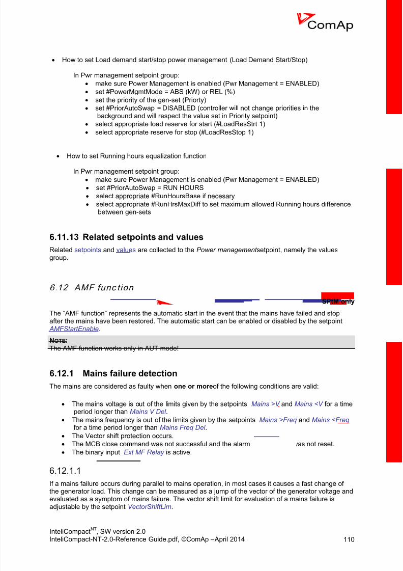
8/15/2019 InteliCompact NT 2.0 Reference Guide
http://slidepdf.com/reader/full/intelicompact-nt-20-reference-guide 110/287
InteliCompactNT
, SW version 2.0InteliCompact-NT-2.0-Reference Guide.pdf, ©ComAp – April 2014 110
How to set Load demand start/stop power management (Load Demand Start/Stop)
In Pwr management setpoint group:
make sure Power Management is enabled (Pwr Management = ENABLED)
set #PowerMgmtMode = ABS (kW) or REL (%)
set the priority of the gen-set (Priorty) set #PriorAutoSwap = DISABLED (controller will not change priorities in the
background and will respect the value set in Priority setpoint)
select appropriate load reserve for start (#LoadResStrt 1)
select appropriate reserve for stop (#LoadResStop 1)
How to set Running hours equalization function
In Pwr management setpoint group:
make sure Power Management is enabled (Pwr Management = ENABLED)
set #PriorAutoSwap = RUN HOURS
select appropriate #RunHoursBase if necesary
select appropriate #RunHrsMaxDiff to set maximum allowed Running hours differencebetween gen-sets
6.11.13 Related setpoints and values
Related setpoints and values are collected to the Power management setpoint, namely the valuesgroup.
6.12 AMF func t ion
SPtM only
The “ AMF function” represents the automatic start in the event that the mains have failed and stopafter the mains have been restored. The automatic start can be enabled or disabled by the setpoint AMFStartEnable.
NOTE: The AMF function works only in AUT mode!
6.12.1 Mains failure detection
The mains are considered as faulty when one or more of the following conditions are valid:
The mains voltage is out of the limits given by the setpoints Mains >V and Mains <V for a timeperiod longer than Mains V Del .
The mains frequency is out of the limits given by the setpoints Mains >Freq and Mains <Freq for a time period longer than Mains Freq Del .
The Vector shift protection occurs.
The MCB close command was not successful and the alarm MCB fail still was not reset.
The binary input Ext MF Relay is active.
Vector shift6.12.1.1
If a mains failure occurs during parallel to mains operation, in most cases it causes a fast change ofthe generator load. This change can be measured as a jump of the vector of the generator voltage and
evaluated as a symptom of mains failure. The vector shift limit for evaluation of a mains failure isadjustable by the setpoint VectorShiftLim.

8/15/2019 InteliCompact NT 2.0 Reference Guide
http://slidepdf.com/reader/full/intelicompact-nt-20-reference-guide 111/287
InteliCompactNT
, SW version 2.0InteliCompact-NT-2.0-Reference Guide.pdf, ©ComAp – April 2014 111
NOTE: Vector shift is evaluated only while the gen-set is working parallel to the mains.
6.12.2 Healthy mains detection
The mains are considered to be healthy when all of following conditions are valid:
The mains voltage is within the limits given by the setpoints Mains >V and Mains <V .
The mains frequency is within the limits given by the setpoints Mains >Freq and Mains <Freq.
The alarm MCB fail is not active.
The binary input Ext MF Relay is not active.
NOTE: There is a hysteresis for Mains under and over voltage added in the same way as in the InteliLiteNTfamily.
6.12.3 The AMF procedureWhen the mains failure is detected, the following steps are performed:
1. If the setpoint MCB Opens On is set to MAINSFAIL, the MCB is opened2. The timer for automatic start of the gen-set EmergStart Del begins to count down.3. After the timer has elapsed, the gen-set is started.
NOTE: The automatic start of the gen-set due to AMF function can be disabled by the inputMainsFailBlock . If the gen-set is already running and the input is activated, the gen-set willcool down and stop. The control of breakers is not affected by this input.
4. If the setpoint MCB Opens On is set to GENRUN, the MCB is opened once the generator
voltage is within limits.5. If the mains are restored to health and the gen-set is still not connected to the load, the
controller interrupts the startup process and closes back the MCB.6. The GCB is closed and the gen-set begins to supply the load.7. After the mains are restored to normal, the timer MainsReturnDel begins to count down and
when finished, either reverse synchronizing or switchover is performed. This depends on thebinary input RevSyncDisable. If active, switchover is performed instead of reverse
synchronizing.8. Maximum time between closing of GCB and opening MCB is given by the setpoint
BreakerOverlap. 9. If no demand for parallel operation is active (binary input Rem Start/Stop), the GCB is opened
and the gen-set cools down and a stop follows.
NOTE: For a description of how to make a test of AMF function, see the chapter operating modes, TESTmode paragraph.
6.13 Engine cool down and stop
The cool down phase follows after the stop command has been issued and the GCB has beenopened.
Duration of the cool down phase is determined by the setpoint Cooling Time.
Cooling is performed either at nominal speed (generator voltage and frequency protectionsare evaluated) or at idle speed (generator voltage and frequency protections are notevaluated). Selection of the speed is done by the setpoint Cooling Speed .

8/15/2019 InteliCompact NT 2.0 Reference Guide
http://slidepdf.com/reader/full/intelicompact-nt-20-reference-guide 112/287
InteliCompactNT
, SW version 2.0InteliCompact-NT-2.0-Reference Guide.pdf, ©ComAp – April 2014 112
The cool down can be finished manually in MAN mode by pressing the STOP button.
If a new start request comes, the cool down will be interrupted and the gen-set will go back tothe stabilization phase. If the cooling was at nominal speed, the stabilization timers will notcount down again so the GCB is immediately ready to be closed.
When the cool down is finished, the output Fuel Solenoid is de-energized and Stop Solenoid is
energized. The engine will stop within the time period determined by the setpoint Stop Time. If theengine does not stop within this time, the alarm Stop fail will be issued.
The output Stop Solenoid is energized until the engine is stopped, but at least for the duration of StopTime. If the Stop time has elapsed and the engine has still not stopped, the stop solenoid is de-energized for 5 s and then energized again for max. Stop time and this repeats until the engine isstopped.
The output Ignition is continuously energized until the engine is stopped.
6.13.1 Stopped gen-set evaluation
The gen-set is considered as stopped when all of following conditions are valid:
The engine speed is lower than 2 revs (RPM).
The generator voltage in all phases is lower than 50 V.
None of additional running indication signals is active. See the chapter Speed sensing fordetails.
6.14 Alarm management
The controller evaluates two levels of alarms. Level 1 – yellow alarm – is a pre-critical alarm that is
only informative and does not take any action regarding gen-set control. Level 2 – red alarm – represents a critical situation, where an action must be taken to prevent damage of the gen-set ortechnology.
One alarm of any type can be assigned to each binary input
Two alarms (one yellow and one red type) can be assigned to each analog input
There are also built-in alarms with fixed alarm types.
Each alarm is written to the Alarmlist.
Each alarm causes a record to be written into the history log.
Each alarm activates the Alarm and Horn output.
Each alarm can cause sending of a SMS message or an e-mail.

8/15/2019 InteliCompact NT 2.0 Reference Guide
http://slidepdf.com/reader/full/intelicompact-nt-20-reference-guide 113/287
InteliCompactNT
, SW version 2.0InteliCompact-NT-2.0-Reference Guide.pdf, ©ComAp – April 2014 113
Time [s]
Analogvalue
Yellow alarm
level
Red alarm
level
t < alarm delay
alarm
delay
alarm
delay
No alarm
issued
Yellow alarm
issued
Red alarm
issued
ANALOG INPUT ALARM EVALUATION PRINCIPLE
6.14.1 Alarm handling
There are two different alarm categories regarding the period when the alarms are evaluated.The category is selectable for alarms assigned to binary/analog inputs and fixed for built-inalarms. The categories are the following:
1) The alarm is evaluated all the time when the controller is switched on.2) The alarm is evaluated only when the engine is running. This type should be used
for e.g. oil pressure. These alarms begin to be evaluated after the engine has been
started with the delay given by the setpoint ProtectHoldOff . 3) The alarm is evaluated only when the generator is excited . These alarms begin to be
evaluated after the engine has been started and Max Stab Time has elapsed or theGCB has been closed. They remain evaluated until cooling has finished. OnlyGenerator under/overvoltage, Generator voltage unbalance and Generatorunder/overfrequency belong to this category. This category is not configurable tobinary and analog input alarms.
If an alarm is being evaluated and the appropriate alarm condition is fulfilled, the delay ofevaluation will start to run. The delay is adjustable by a setpoint (in the case of built-in alarms,analog input alarms) or is fixed to 500ms (in the case of binary input alarms). If the conditionspersist, the alarm will activate. The alarm will not activate if the condition is dismissed whilethe delay is still running.
After pressing the Fault reset button or activating the binary input FaultResButton, all activealarms change to confirmed state. Confirmed alarms will disappear from the Alarmlist as soonas the respective condition dismisses. If the condition is dismissed before acknowledging thealarm, the alarm will remain in the Alarmlist as Inactive. See also the Browsing alarms chapter.
NOTE: The input Sd Override can be used for temporary disabling of red alarms to shutdown the engine. This
input may be used in situations where providing the power is extremely important – e.g. if the gen-setdrives pumps for fire extinguishers (sprinklers).
6.14.2 Alarm states
An alarm can have following states:

8/15/2019 InteliCompact NT 2.0 Reference Guide
http://slidepdf.com/reader/full/intelicompact-nt-20-reference-guide 114/287
InteliCompactNT
, SW version 2.0InteliCompact-NT-2.0-Reference Guide.pdf, ©ComAp – April 2014 114
Active alarm: the alarm condition persists, alarm delay has elapsed.
Inactive alarm: the alarm condition has disappeared, but the alarm has not been confirmed.
Confirmed alarm: the alarm condition persists, but the alarm has already been confirmed.
6.14.3 Alarm types – Yellow level
The yellow alarm indicates that a value or parameter is out of normal limits, but has still not reachedcritical level. Obviously it is indicated by a yellow colour. This alarm does not cause any actionsregarding the gen-set control.
Warning (WRN)6.14.3.1
The Warning alarm does not perform any actions regarding gen-set control.
6.14.4 Alarm types – Red level
The red level alarm indicates that a critical level of the respective value or parameter has been
reached. Obviously it is indicated by red colour. The controller will take one of the following actions:
Breaker open and cool down (BOC)6.14.4.1
The BOC (electric trip) alarm category is used above all for built-in alarms assigned to the generator
electric values (voltage, current, power, etc.). The GCB is opened immediately, but after that theengine will perform the standard stop procedure including cooling.
Slow stop (STP)6.14.4.2
The Slow stop alarm differs from the BOC in that the gen-set will perform a soft unload before openingthe GCB (if possible). After that the standard stop procedure including cooling follows.
NOTE: In the MINT application if the power management is active and a slow stop alarm occurs, the controllerwill wait until another gen-set is started (if there is at least one available) before unloading andstopping the gen-set. The maximum time the controller will wait is given by the setpoint #SlowStopDel .
Shutdown (SD)6.14.4.3
The Shutdown alarm opens the GCB immediately and stops the engine immediately without cooling.
NOTE: It is not possible to start the engine if any red level protection is active or not confirmed.
CAUTION! The gen-set can start by itself after acknowledging the alarms if there is no longer an active red alarmand the controller is in AUT or TEST mode!
6.14.5 Sensor fail detection (FLS)
If the measured resistance (or voltage or current in case of IGS-PTM module) on an analog inputexceeds the valid range, a sensor fail will be detected and a sensor fail message will appear in the Alarmlist. The valid range is defined by the most-left (RL) and most-right (RH) points of the sensorcharacteristic ±12.5% from RH-RL.

8/15/2019 InteliCompact NT 2.0 Reference Guide
http://slidepdf.com/reader/full/intelicompact-nt-20-reference-guide 115/287
InteliCompactNT
, SW version 2.0InteliCompact-NT-2.0-Reference Guide.pdf, ©ComAp – April 2014 115
Ω
Bar
10 191
10
0
180
10.6
First point of
the curveLast point of the
curve
100% of the sensor range
12.5% of the
sensor range
S e n s
o r f a i l a
r e a
Sensor fail limit would be -1
Ohm what is physically
imposible so sensor fail is notdetected even for 0 ohm
Sensor fail limit
SENSOR FAIL EVALUATION EXAMPLE
NOTE: The sensor fail alarm does not influence the gen-set operation.
6.14.6 Remote alarm messaging
If a GSM modem and/or Internet Bridge are connected to the controller, the controller can send SMSmessages and/or emails at the moment when a new alarm appears in the Alarmlist. The message willcontain a copy of the Alarmlist.
To enable this function, you should select with setpoints Yel Alarm Msg and Red Alarm Msg the levelsof alarms to be announced (red/yellow/both) and also enter a valid GSM phone number and/or e-mailaddress to the setpoints TelNo/Addr Ch1 and TelNo/Addr Ch2 . It is possible to set either a GSMnumber or e-mail at both setpoints.
The list of all supported terminals shows the table below:
TerminalActive alarmsms
Active eventsms
Active alarmemail
Active eventemail
IB-Lite NA NA yes yes
IB-NT yes yes yes yes*
IL-NT-GPRS yes yesNotsupported
Notsupported
*since IB-NT 2.2.0
Controller is capable to detect which communication terminal is connected to the network and sendthe email/SMS via the active one. InternetBridge-NT is preferred terminal if more possibilities aredetected.

8/15/2019 InteliCompact NT 2.0 Reference Guide
http://slidepdf.com/reader/full/intelicompact-nt-20-reference-guide 116/287
InteliCompactNT
, SW version 2.0InteliCompact-NT-2.0-Reference Guide.pdf, ©ComAp – April 2014 116
NOTE: An internet module must be available for sending e-mails and a GSM modem is necessary for sendingSMS. See the Communications chapter for more information.
6.14.7 Alarmlist
Alarmlist is a container of active and inactive alarms. It will appear automatically on the controllerdisplay, if a new alarm occurs, or can be displayed manually from the display menu
It can contain up to 16 alarms, but the first 7 are visible on the screen. If it is full, recentlycoming alarms are not displayed.
Active alarms are shown as inverted, not yet confirmed alarms are marked with asteriskbefore them.
An alarm message in the alarmlist begins with a prefix, which represents the alarm type(e.g. WRN ). Then the alarm name follows. In some cases the prefix can be omitted.
NOTE: The Alarmlist can be read out from the controller via Modbus. See the Modbus description chapter.
6.14.8 ECU AlarmlistThe ECU Alarmlist contains alarms that are received from the ECU. The alarms are represented bythe Diagnostic Trouble Code, which contains information about the subsystem where the alarmoccurred, the alarm type and the alarm occurrence counter.
The most common fault codes are translated into text form. Other fault codes are displayed as anumeric code and the engine fault codes list must be used to determine the reason.
NOTE: The ECU AlarmList is visible only if an ECU is configured.
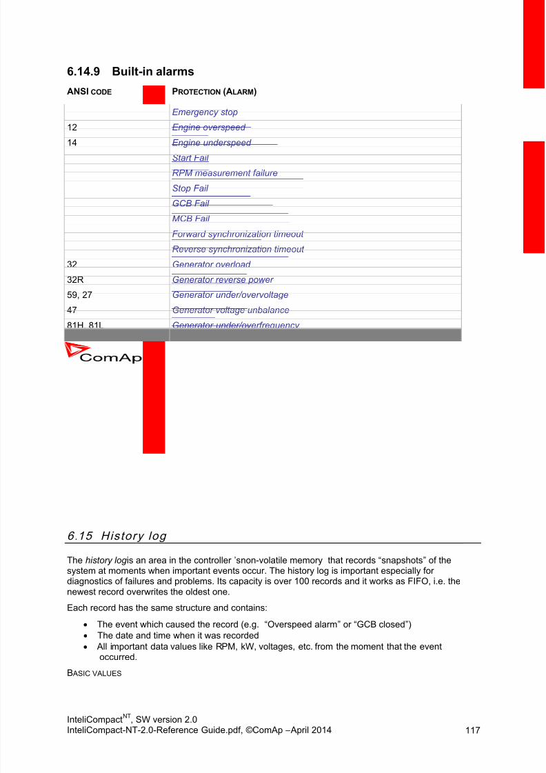
8/15/2019 InteliCompact NT 2.0 Reference Guide
http://slidepdf.com/reader/full/intelicompact-nt-20-reference-guide 117/287
InteliCompactNT
, SW version 2.0InteliCompact-NT-2.0-Reference Guide.pdf, ©ComAp – April 2014 117
6.14.9 Built-in alarms
ANSI CODE PROTECTION (ALARM)
Emergency stop
12 Engine overspeed
14 Engine underspeed
Start Fail
RPM measurement failure
Stop Fail
GCB Fail
MCB Fail
Forward synchronization timeout
Reverse synchronization timeout
32 Generator overload
32R Generator reverse power
59, 27 Generator under/overvoltage
47 Generator voltage unbalance
81H, 81L Generator under/overfrequency
51 Generator overcurrent
50 Generator short current
46 Generator current unbalance
47 Phase sequence
Maintenance timer
Charging alternator fail
Battery voltage
Governor output at limit
AVR output at limit
Battery flat
Low backup battery
6.15 History logThe history log is an area in the controller ’s non-volatile memory that records “snapshots” of thesystem at moments when important events occur. The history log is important especially fordiagnostics of failures and problems. Its capacity is over 100 records and it works as FIFO, i.e. thenewest record overwrites the oldest one.
Each record has the same structure and contains:
The event which caused the record (e.g. “Overspeed alarm” or “GCB closed”)
The date and time when it was recorded
All important data values like RPM, kW, voltages, etc. from the moment that the eventoccurred.
B ASIC VALUES

8/15/2019 InteliCompact NT 2.0 Reference Guide
http://slidepdf.com/reader/full/intelicompact-nt-20-reference-guide 118/287
InteliCompactNT
, SW version 2.0InteliCompact-NT-2.0-Reference Guide.pdf, ©ComAp – April 2014 118
NAME ABBREVIATION DESCRIPTION
Number NumRow number (0 corresponds to the last record, -1 to theprevious one, etc.)
Reason ReasonReason for history record (any event or alarm related to thegen-set
Date Date Date
Time Time Time
RPM RPM Engine rotations per minute
Power Pwr Generator active power
Power Factor PF Generator power factor
Load Character LChr Generator load character
Generator Voltage Vg1 Generator voltage Ph1
Generator Voltage Vg2 Generator voltage Ph2
Generator Voltage Vg3 Generator voltage Ph3 Generator Current Ig1 Generator current Ph1
Generator Current Ig2 Generator current Ph2
Generator Current Ig3 Generator current Ph3
Oil Pressure OilP Oil pressure measured on the first analog input
Engine Temperature EngT Engine temperature measured on the second analog input
Fuel Level FLvl Fuel level measured on the third analog input
Analog Input Module AIM1 Analog input 1 on IG-IOM extension module
Analog Input Module AIM2 Analog input 2 on IG-IOM extension module
Analog Input Module AIM3 Analog input 3 on IG-IOM extension module Analog Input Module AIM4 Analog input 4 on IG-IOM extension module
Binary Inputs BIN Controller binary inputs
Binary Input Module BIM Binary inputs on IG-IOM extension module
Binary Inputs/OutputsExtension
BIOE Extension Module Binary Inputs/Outputs
Binary Outputs BOUT Controller binary outputs
Binary Outputs Module BOM Binary outputs on IG-IOM extension module
Speed Regulator Output SROSpeed regulator output (see chapter Speed GovernorInterface)
Voltage Regulator Output VRO Voltage regulator output (see chapter AVR Interface)
ECU values6.15.1.1
ECU VALUES
NAME ABBREVIATION
ECU Fuel rate EFR
ECU Coolant Temperature ECT
ECU Intake temperature EIT
ECU Oil pressure EOPECU Oil temperature EOT

8/15/2019 InteliCompact NT 2.0 Reference Guide
http://slidepdf.com/reader/full/intelicompact-nt-20-reference-guide 119/287
InteliCompactNT
, SW version 2.0InteliCompact-NT-2.0-Reference Guide.pdf, ©ComAp – April 2014 119
ECU Boost pressure EBP
ECU Percent load at current speed EPL
ECU Fuel Level EFL
ECU Fault Code FC
Failure Mode Identifier FMI
SPtM specific values6.15.1.2
SPTM VALUES
NAME ABBREVIATION DESCRIPTION
Mains Frequency Mfrq Mains frequency
Mains Voltage Vm1 Mains voltage Ph1
Mains Voltage Vm2 Mains voltage Ph2
Mains Voltage Vm3 Mains voltage Ph3
Mains Active Power Pmns Mains active power
Mains Reactive Power Qmns Mains reactive power
Mains Power Factor MPF Mains power factor
Mains Load Character MLCh Mains load character
Mains Vector Shift MVS Mains vector shift
MINT specific values6.15.1.3
Information about gen-sets with GCB closed and their overall P and Q. Values can be also found in
LiteEdit Values / Pwr Management and Info (LE ver. 4.4 and higher).MINT VALUES
NAME ABBREVIATION DESCRIPTION
Bus Frequency Bfrq Bus frequency
Bus Voltage Vb1 Bus voltage Ph1
Bus Voltage Vb2 Bus voltage Ph2
Bus Voltage Vb3 Bus voltage Ph3
ActualReserve Ares Actual reserve
GensLoaded16 GL16 Each bit if set represents gent-set with its GCB closed
GensLoaded32 GL32 Each bit if set represents gent-set with its GCB closed
Running ActPwr TRPA Overall power from gen-set with its GCB closed
Running Q-Pwr TRQAOverall reactive power from gen-set with its GCBclosed
Running Nominal Power TRPN Total running nominal power
Available Nominal Power APN Available nominal power

8/15/2019 InteliCompact NT 2.0 Reference Guide
http://slidepdf.com/reader/full/intelicompact-nt-20-reference-guide 120/287
InteliCompactNT
, SW version 2.0InteliCompact-NT-2.0-Reference Guide.pdf, ©ComAp – April 2014 120
NOTE: The contents of the history log will be deleted after programming firmware or configuration into thecontroller.
The history log can be displayed on the controller screen or in LiteEdit. If an archive (*.ail file) is savedin LiteEdit, it will also contain the history log. The archive can be later opened in offline mode to view
the history log offline.
NOTE: The first history record after the controller is switched on, programmed or a watchdog reset occurscontains diagnostic values instead of operational values. Some fields in these records may seem tohave nonsense values. Do not take these values into account.
6.16 Exercis e timers
There are two exercise timers available in the controller, which are based on the RTC clock. They areboth identical.
Each timer has the following settings (in the Date/Time setpoint group).
8/15/2019 InteliCompact NT 2.0 Reference Guide
http://slidepdf.com/reader/full/intelicompact-nt-20-reference-guide 121/287
InteliCompactNT
, SW version 2.0InteliCompact-NT-2.0-Reference Guide.pdf, ©ComAp – April 2014 121
6.16.1 MINT
No FuncThere is no function other than activation of the binary outputs Exerc Timer 1 or ExercTimer 2 .
Mode
OFF
When this option is chosen, the Timer output is also internally connected to the
Remote OFF binary input.
AutoRun When this option is chosen, the Timer directly starts gen-set (in AUT mode).
6.16.2 SPtM
No FuncThere is no other function besides binary output Exerc Timer 1 or Exerc Timer 2 activation.
ModeOFF
When this option is chosen, the Timer output is also internally connected to theRemote OFF binary input.
MFail BlkWhen this option is chosen, the Timer output is also internally connected to theMainsFailBlock binary input.
TESTWhen this option is chosen, the Timer output is also internally connected to theRemote TEST binary input.
TESTOnLd
When this option is chosen, the Timer output is also internally connected to the RemTEST OnLd binary input.
The timer outputs are available as binary outputs Exerc Timer 1 and Exerc Timer 2 .
NOTE
:
Timers are activated even in the middle of the cycle. This means that even when the controller isswitched on after the moment when the timer should have been started and before it should havefinished, the timer is activated for the remainder of the duration period.
Timer functions can be activated only in AUT mode (not in OFF, MAN or TEST). There are 2 timers.
In the event that both Timers are active at the same time, Timer 1 has a higher priority than Timer 2 .
6.17 Analog sw itches
One analog switch (comparator) is assigned to each analog input to the controller. The switches aresuitable for preheat control, day tank fuel pump control and others.
Associated setpoints are located in the setpoint group Analog switches.
One binary output is associated with each switch
The behaviour of the switch depends on the adjustment of the setpoints.

8/15/2019 InteliCompact NT 2.0 Reference Guide
http://slidepdf.com/reader/full/intelicompact-nt-20-reference-guide 122/287
InteliCompactNT
, SW version 2.0InteliCompact-NT-2.0-Reference Guide.pdf, ©ComAp – April 2014 122
SWITCH
OUTPUT
OFF
ON
OFF
ON
ANALOG VALUELEVEL OFF LEVEL ON
LEVEL ON LEVEL OFF ANALOG VALUE
SWITCH
OUTPUT
LEVEL ON > LEVEL OFF
LEVEL ON < LEVEL OFF
6.18 Power sw itch
There is also one switch assigned to the gen-set active power, which is called the Power switch. Thesetpoints for on and off level adjustment are located in the setpoint group Analog switches. The outputis provided as the binary output Power switch.
The behaviour of the switch depends on the adjustment of the setpoints.
SWITCH
OUTPUT
OFF
ON
OFF
ON
ANALOG VALUELEVEL OFF LEVEL ON
LEVEL ON LEVEL OFF ANALOG VALUE
SWITCH
OUTPUT
LEVEL ON > LEVEL OFF
LEVEL ON < LEVEL OFF
6.19 Regulat ion loop s
The following table shows which setpoints influence regulation in which situation.
6.19.1 SPtM
SPEED REGULATOR OUTPUT FOR SINGLE GEN-SET APPLICATION
ISLAND LOADED ISLAND PARALLEL TO MAINS LOADED IN PARALLEL
TO MAINS
Running
GCB opened
GCB closed
MCB opened Synchronizing
GCB closed
MCB closed

8/15/2019 InteliCompact NT 2.0 Reference Guide
http://slidepdf.com/reader/full/intelicompact-nt-20-reference-guide 123/287
InteliCompactNT
, SW version 2.0InteliCompact-NT-2.0-Reference Guide.pdf, ©ComAp – April 2014 123
SRO output value =Speed Gov Bias
SRO output value =Speed Gov Bias
Speed/frequencycontrol loop: Freq Gain Freq Int Angle control loop: Angle Gain
Power control loop: Load Gain Load Int
VOLTAGE REGULATOR OUTPUT FOR SINGLE GEN-SET APPLICATION
ISLAND LOADED ISLAND PARALLEL TO MAINS LOADED IN PARALLEL TO MAINS
RunningGCB opened
GCB closedMCB opened
SynchronizingGCB closedMCB closed
Voltage control loop: Voltage Gain Voltage Int
Voltage control loop: Voltage Gain Voltage Int
Voltage control loop: Voltage Gain Voltage Int
Power factor control loop: PF Gain PF Int
6.19.2 MINT
SPEED REGULATOR OUTPUT FOR MULTIPLE GEN-SET APPLICATION
ISLAND LOADED ISLAND PARALLEL TO MAINS LOADED IN
PARALLEL TO MAINS
RunningGCB opened
GCB closedMCB opened
SynchronizingGCB closedMCB closed
SRO output value =Speed Gov Bias
Speed/frequency controlloop:
LoadShare Gain LoadShare Int
background nominalfrequency matching
Speed/frequencycontrol loop:
Freq Gain Freq Int
Angle control loop: Angle Gain
Power control loop: Load Gain Load Int
VOLTAGE REGULATOR OUTPUT FOR MULTIPLE GEN-SET APPLICATION
MULTIPLE ISLAND MULTIPLE LOADED
ISLAND MULTIPLE PARALLEL TO
MAINS MULTIPLE LOADED IN PARALLEL
TO MAINS
RunningGCB opened
GCB closedMCB opened
SynchronizingGCB closedMCB closed
Voltage controlloop: Voltage Gain Voltage Int
Voltage controlloop: VAr Share Gain VAr Share Int
Voltage control loop: Voltage Gain Voltage Int
Power factor control loop: PF Gain PF Int
The following regulation loops are built into the controller. All of them are PI type except angle loop,which is P type.
NOTE:Since IC-NT SW v. 1.4.1 only the first controller (with the lowest address at the CAN has) activevoltage control loop. Other controllers are adapting voltage according to bus to the first one. Allcontrollers have active VAr Share regulation loop.

8/15/2019 InteliCompact NT 2.0 Reference Guide
http://slidepdf.com/reader/full/intelicompact-nt-20-reference-guide 124/287
InteliCompactNT
, SW version 2.0InteliCompact-NT-2.0-Reference Guide.pdf, ©ComAp – April 2014 124
6.19.3 Regulation control loops overview
Speed/frequency control loop6.19.3.1
The speed/frequency control loop is active during the synchronization, when the gen-set frequency iscontrolled to the same value as the mains or bus have, i.e. to achieve zero slip frequency.
Differential angle control loop6.19.3.2
The differential angle control loop is active during the synchronization, when the “near to zero” slipfrequency has been successfully achieved and then the differential angle between generator andmains/bus voltage shall be reduced to zero.
Power control loop6.19.3.3
The power control loop is active during the parallel to mains operation. The recognition of parallel tomains operation is done on the basis of the binary input MCB feedback . In MINT the setpoint#SysLdCtrl PtM must be also set to BASELOAD.
Load sharing control loop6.19.3.4The load sharing control loop is active in MINT, whenever the GCB is closed and the binary input MCBfeedback is not active or the setpoint #SysLdCtrl PtM is in LDSHARING position.
Voltage control loop6.19.3.5
The voltage control loop is active during synchronization (the generator voltage is controlled to thesame value as the mains or bus have) and during island operation in SPtM (the gen-set voltage iscontrolled to the nominal voltage). During multiple island operation in MINT, the voltage control loop isalso running “in the background” of the VAr sharing loop (using P, I parameters multiplied by 0.1) tomaintain the voltage at the nominal level.
NOTE:
Since IC-NT SW v. 1.4.1 only the first controller (with the lowest address at the CAN has) activevoltage control loop. Other controllers are adapting voltage according to bus to the first one. Allcontrollers have active VAr Share regulation loop.
Power factor control loop6.19.3.6
The power factor control loop is active during the parallel to mains operation. The recognition ofparallel to mains operation is done on the basis of the binary input MCB feedback .
VAr sharing control loop6.19.3.7
The VAr sharing control loop is active during multiple island operation in MINT application.
6.19.4 PI regulation adjustment
The exact adjustment of a PI loop always depends on the engine and generator characteristics.However, a general rule can be followed in the beginning of the adjustment process:
Prepare the system for adjustment, i.e. set the limits for related alarms temporarily to valueswhich will disable the alarms, set the synchro timeout to the maximum value, etc.
Adjust the gain to 5% and integration to 0%.
Switch the gen-set to MAN mode, start it and put it into the operation phase, where theappropriate regulation loop is active.
Increase the gain slightly until the controlled quantity starts to oscillate. Then put it back toapprox. one half of the value where the oscillations started.

8/15/2019 InteliCompact NT 2.0 Reference Guide
http://slidepdf.com/reader/full/intelicompact-nt-20-reference-guide 125/287
InteliCompactNT
, SW version 2.0InteliCompact-NT-2.0-Reference Guide.pdf, ©ComAp – April 2014 125
Increase the integrative factor slightly to achieve acceptable response to changes. Too smallan I-factor will cause an excessively slow response, while too high an I-factor will causeovershooting or even oscillations.
NOTE: It may be helpful to disable issuing the GCB close command when adjusting synchronization loops.
Adjust the setpoint Phase Window to 0 to disable it. Adjust the setpoint back to its original value afterthe adjustment is finished.
CAUTION! Be ready to press the emergency stop button in the event that the regulation loop starts to behaveunacceptably.

8/15/2019 InteliCompact NT 2.0 Reference Guide
http://slidepdf.com/reader/full/intelicompact-nt-20-reference-guide 126/287
InteliCompactNT
, SW version 2.0InteliCompact-NT-2.0-Reference Guide.pdf, ©ComAp – April 2014 126
7 Setpoints
Setpoints are analog, binary or special data objects which are used for adjusting the controller to thespecific environment. Setpoints are organized into groups according to their meaning. Setpoints can
be adjusted from the controller front panel, PC, MODBUS, etc.
7.1 Passwo rd protect ion
Each setpoint can be protected by a password against unauthorized changes. Password protectioncan be assigned to the setpoints during the configuration procedure. See the chapter Operator guide for instructions on how to enter and modify a password. See also the LiteEdit help to learn aboutworking with a password in LiteEdit.
7.2 Setpoint syn chro nization
Setpoints marked with a “#” sign at the beginning of their names are synchronized with othercontrollers present on the CAN bus line, i.e. the system will ensure that the respective setpoint willhave an identical value in each connected controller. If the setpoint is changed in one controller, thesame change will occur in all other controllers. This function is necessary especially for MINTapplication, where the system of Power management is based on fact that the respective setpoints areidentical in all controllers.
All parameters marked as shared (“#”) are overwritten during archive download in case there is noanother single controller visible on the CAN bus. In case there is another controller on the CAN bus,the shared parameters are not overwritten.
7.3 Setpoint groups
1. Process Control 2. Basic Settings 3. Comms Settings 4. Engine Params5. Engine Protect 6. Gener Protect 7. Pwr Management 8. AMF Settings
9. Sync/Load Ctrl 10. Volt/PF Control 11. ExtI/O Protect 12. SMS/E-Mail13. AnalogSwitches14. Date/Time 15. Sensors Spec
CAUTION! Do not write setpoints repeatedly (e.g. power control from a PLC by repeated writing of baseloadsetpoint via Modbus) The setpoints are stored in EEPROM memory, which can be overwritten up to10
5 times without risk of damage or data loss, but it may become damaged, when the allowed number
of writing cycles is exceeded!

8/15/2019 InteliCompact NT 2.0 Reference Guide
http://slidepdf.com/reader/full/intelicompact-nt-20-reference-guide 127/287
InteliCompactNT
, SW version 2.0InteliCompact-NT-2.0-Reference Guide.pdf, ©ComAp – April 2014 127
7.3.1 Setpoints – Process Control
1. Baseload 2. Base PF 3. AMFStartEnable 4. Export Limit
5. Export kW6. #SysLdCtrl PtM 7. #SysBaseLoad 8. #SysPwrFactor 9. Synchro Enable 10. PeakLevelStart11. PeakLevelStop12. PeakAutS/S Del 13. #Neutral cont
7.3.2 Setpoints – Basic Settings
1. ControllerName 2. Nominal Power 3. Nomin Current 4. CT Ratio 5. EF CT Ratio 6. Im/EF CT Ratio 7. Im/EF input 8. Nominal Volts 9. PT Ratio 10. Vm PT Ratio 11. Vb PT Ratio 12. Nominal Freq
13. Nominal RPM 14. Gear Teeth 15. ControllerMode 16. Reset To MAN 17. Backlight time
7.3.3 Setpoints – Comms Settings
1. ControllerAddr 2. COM1 Mode 3. COM2 Mode
4. ModemIniString 5. ModbusComSpeed 6. CAN Bus Mode 7. IBLite IP Addr 8. IBLite NetMask 9. IBLite GateIP 10. IBLite DHCP 11. ComAp Port 12. APN Name 13. APN UserName 14. APN UserPass 15. AirGate 16. AirGate IP
17. SMTP UserName 18. SMTP UserPass 19. SMTP Server IP
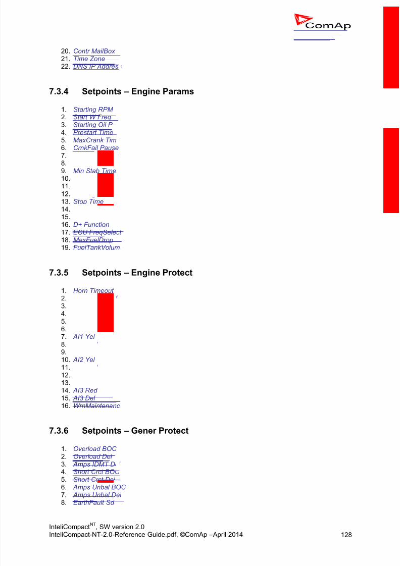
8/15/2019 InteliCompact NT 2.0 Reference Guide
http://slidepdf.com/reader/full/intelicompact-nt-20-reference-guide 128/287
InteliCompactNT
, SW version 2.0InteliCompact-NT-2.0-Reference Guide.pdf, ©ComAp – April 2014 128
20. Contr MailBox 21. Time Zone 22. DNS IP Address
7.3.4 Setpoints – Engine Params
1. Starting RPM 2. Start W Freq3. Starting Oil P 4. Prestart Time 5. MaxCrank Time 6. CrnkFail Pause 7. Crank Attempts 8. Idle Time 9. Min Stab Time 10. Max Stab Time 11. Cooling Speed 12. Cooling Time 13. Stop Time 14. SDVentil Time15. Fuel Solenoid16. D+ Function 17. ECU FreqSelect 18. MaxFuelDrop 19. FuelTankVolume
7.3.5 Setpoints – Engine Protect
1. Horn Timeout
2. ProtectHoldOff 3. Overspeed Sd 4. Batt Overvolt5. Batt Undervolt6. Batt Volt Del 7. AI1 Yel 8. AI1 Red 9. AI1 Del 10. AI2 Yel 11. AI2 Red 12. AI2 Del 13. AI3 Yel 14. AI3 Red
15. AI3 Del 16. WrnMaintenance
7.3.6 Setpoints – Gener Protect
1. Overload BOC 2. Overload Del 3. Amps IDMT Del 4. Short Crct BOC 5. Short Crct Del 6. Amps Unbal BOC
7. Amps Unbal Del8. EarthFault Sd

8/15/2019 InteliCompact NT 2.0 Reference Guide
http://slidepdf.com/reader/full/intelicompact-nt-20-reference-guide 129/287
InteliCompactNT
, SW version 2.0InteliCompact-NT-2.0-Reference Guide.pdf, ©ComAp – April 2014 129
9. EarthFault Del 10. Gen >V Sd 11. Gen <V BOC 12. Gen V Del 13. Volt Unbal BOC 14. Volt Unbal Del
15. Gen >Freq BOC 16. Gen <Freq BOC 17. Gen Freq Del 18. BusMeasError 19. Reverse Pwr BOC 20. Reverse Pwr Del 21. ExcitationLoss 22. ExctLoss Del
7.3.7 Setpoints – Pwr ManagementMINT only
1. Pwr Management 2. Pwr Manag Del3. #PowerMgmtMode4. Priority 5. #PriorAutoSwap6. #SysAMFstrtDel 7. #SysAMFstopDel 8. #LoadResStrt 1 9. #LoadResStop 1 10. #LoadResStrt 2 11. #LoadResStop 2 12. #Min Run Power 13. #NextStrt Del 14. #OverldNextDel 15. #NextStopDel 16. #SlowStopDel 17. RunHoursBase 18. #RunHrsMaxDiff 19. #PwrBnChngDlUp20. #PwrBnChngDlDn
7.3.8 Setpoints – AMF SettingsSPtM only
1. EmergStart Del 2. MainsReturnDel 3. Mains >V 4. Mains <V 5. Mains V Del 6. Mains >Freq 7. Mains <Freq 8. Mains Freq Del 9. VectorShiftLim 10. Transfer Del 11. MCB Close Del 12. MCB Opens On 13. RetFromIsland
14. BreakerOverlap 15. ReturnFromTEST

8/15/2019 InteliCompact NT 2.0 Reference Guide
http://slidepdf.com/reader/full/intelicompact-nt-20-reference-guide 130/287
InteliCompactNT
, SW version 2.0InteliCompact-NT-2.0-Reference Guide.pdf, ©ComAp – April 2014 130
16. MCB Logic
7.3.9 Setpoints – Sync/Load Ctrl
1. Speed Gov Char 2. Speed Gov Bias 3. SpeedGovLowLim4. SpeedGovHiLim5. TauSpeedActuat 6. Voltage Window 7. Phase Window 8. Dwell Time 9. Freq Gain 10. Freq Int 11. Angle Gain 12. Load Ramp 13. Load Gain 14. Load Int 15. GCB Open Level 16. GCB Open Del 17. Sync Timeout 18. LoadShare Gain19. LoadShare Int
7.3.10 Setpoints – Volt/PF Control
1. AVRi Bias 2. Voltage Gain 3. Voltage Int
4. PF Gain 5. PF Int 6. VAr Share Gain 7. VAr Share Int
7.3.11 Setpoints – ExtI/O Protect
1. IOM AI1 Yel2. IOM AI1 Red3. IOM AI1 Del4. IOM AI2 Yel
5. IOM AI2 Red6. IOM AI2 Del7. IOM AI3 Yel8. IOM AI3 Red9. IOM AI3 Del10. IOM AI4 Yel11. IOM AI4 Red12. IOM AI4 Del
7.3.12 Setpoints – SMS/E-Mail
1. Yel Alarm Msg 2. Red Alarm Msg 3. Event Msg

8/15/2019 InteliCompact NT 2.0 Reference Guide
http://slidepdf.com/reader/full/intelicompact-nt-20-reference-guide 131/287
InteliCompactNT
, SW version 2.0InteliCompact-NT-2.0-Reference Guide.pdf, ©ComAp – April 2014 131
4. TelNo/Addr Ch1 5. TelNo/Addr Ch2
7.3.13 Setpoints – AnalogSwitches
1. AnaSwitch1 ON 2. AnaSwitch1 OFF3. AnaSwitch2 ON 4. AnaSwitch2 OFF5. AnaSwitch3 ON 6. AnaSwitch3 OFF 7. PowerSwitch ON 8. PowerSwitch OFF
7.3.14 Setpoints – Date/Time
1. Time Stamp Per2. #SummerTimeMod3. #Time4. #Date5. Timer1 Repeat6. Timer1 ON Time7. Timer1Duration8. Timer1 Function9. Timer2 Repeat10. Timer2 ON Time11. Timer2Duration12. Timer2 Function
7.3.15 Setpoints – Sensors Spec
1. AI1Calibration 2. AI2Calibration 3. AI3Calibration 4. IOM AI1 Calibr 5. IOM AI2 Calibr 6. IOM AI3 Calibr 7. IOM AI4 Calibr

8/15/2019 InteliCompact NT 2.0 Reference Guide
http://slidepdf.com/reader/full/intelicompact-nt-20-reference-guide 132/287
InteliCompactNT
, SW version 2.0InteliCompact-NT-2.0-Reference Guide.pdf, ©ComAp – April 2014 132
8 Values
Values (or quantities) are analog or binary data objects, measured or computed by the controller, thatare intended for reading from the controller screen, PC, MODBUS, etc. Values are organized into
groups according to their meaning.
NOTE: A complete overview of all data objects available in the controller can be exported by LiteEdit into atext file. Open any connection (also offline with a previously saved archive) and go to the menu
Controller -> Generate CFG image.
8.1 Invalid flag
If valid data is available for a particular value, the invalid flag is set to it. This situation may be due tothe following:
The value is not being evaluated in the scope of the current application and configuration.
Sensor fail has been detected on an analog input.
The configured ECU or extension module does not provide the particular value.
The communication with the ECU or extension module is interrupted.
A value containing the invalid flag is displayed as “####” in LiteEdit and on the controller screen. Ifsuch a value is read out via Modbus, it will contain the data 32768 in the case of signed values and65535 in the case of unsigned values.
8.2 Value grou ps
1. Engine 2. Generator 3. Mains 4. Bus 5. Pwr Management 6. Controller I/O 7. Extension I/O 8. Statistics 9. Date/Time 10. Info
8.2.1 Values – Engine
1. RPM 2. W-TerminalFreq 3. ECU State 4. Fuel Rate ECU5. Cool Temp ECU 6. IntakeTemp ECU7. Oil Press ECU 8. Oil Temp ECU 9. BoostPress ECU
10. Perc Load ECU11. FuelLevel ECU

8/15/2019 InteliCompact NT 2.0 Reference Guide
http://slidepdf.com/reader/full/intelicompact-nt-20-reference-guide 133/287
InteliCompactNT
, SW version 2.0InteliCompact-NT-2.0-Reference Guide.pdf, ©ComAp – April 2014 133
12. ECU FreqSelect 13. Speed Request 14. SpeedReq RPM 15. DPF1 Soot Load 16. DPF1 Ash Load
8.2.2 Values – Generator
1. Gen kW 2. Gen kW L13. Gen kW L24. Gen kW L35. Gen kVAr 6. Gen kVAr L17. Gen kVAr L28. Gen kVAr L39. Gen kVA 10. Gen kVA L111. Gen kVA L212. Gen kVA L313. Gen PF 14. Gen Load char 15. Gen PF L116. Gen Lchr L117. Gen PF L218. Gen Lchr L219. Gen PF L320. Gen Lchr L321. Gen Freq22. Gen V L1-N 23. Gen V L2-N 24. Gen V L3-N 25. Gen V L1-L2 26. Gen V L2-L3 27. Gen V L3-L1 28. Gen A L1 29. Gen A L2 30. Gen A L3 31. EarthFaultCurr
8.2.3 Values – MainsSPtM only
1. Mains Freq2. Mains V L1-N3. Mains V L2-N4. Mains V L3-N5. Mains V L1-L26. Mains V L2-L37. Mains V L3-L18. Mains A L3/EF 9. Mains kW I 10. Mains kVAr I 11. Mains PF 12. Mains LChr
13. Load kW 14. Load kVAr

8/15/2019 InteliCompact NT 2.0 Reference Guide
http://slidepdf.com/reader/full/intelicompact-nt-20-reference-guide 134/287
InteliCompactNT
, SW version 2.0InteliCompact-NT-2.0-Reference Guide.pdf, ©ComAp – April 2014 134
15. Load PF 16. Load LChr 17. Slip18. Angle19. MaxVectorShift
8.2.4 Values – BusMINT only
1. Bus Freq2. Bus V L1-N3. Bus V L2-N 4. Bus V L3-N 5. Bus V L1-L2 6. Bus V L2-L3 7. Bus V L3-L1 8. Slip 9. Angle
8.2.5 Values – Pwr ManagementMINT only
1. Actual Reserve 2. Running ActPwr 3. Running Q-Pwr4. Running NomPwr5. Avail Nom Pwr 6. Priority 7. Act Pwr Band
8. Next Pwr Band
8.2.6 Values – Controller I/O
1. Battery Volts2. D+3. Analog Input 14. Analog Input 25. Analog Input 36. Bin Inputs7. Bin Outputs
8. Speed Gov Out9. AVRi Output 10. GSM SignalLvl 11. GSM ErrorRate 12. GSM Diag Code 13. AirGate Diag 14. AirGate ID 15. Modem Status
8.2.7 Values – Extension I/O
1. IOM AI12. IOM AI23. IOM AI3

8/15/2019 InteliCompact NT 2.0 Reference Guide
http://slidepdf.com/reader/full/intelicompact-nt-20-reference-guide 135/287
InteliCompactNT
, SW version 2.0InteliCompact-NT-2.0-Reference Guide.pdf, ©ComAp – April 2014 135
4. IOM AI45. IOM Bin Inp6. ExtM Bin Inp 7. RA Bin Out8. IOM Bin Out
8.2.8 Values – Statistics
1. Energy kWh 2. Energy kVAhr 3. Run Hours 4. Num Starts 5. Maintenance 6. Num E-Stops7. Shutdowns8. TotFuelConsum 9. PerTotFuelCons
8.2.9 Values – Date/Time
1. Time 2. Date
8.2.10 Values – Info
1. Engine State2. Breaker State
3. Timer Text4. Timer Value5. FW Version6. FW Branch7. PasswordDecode8. CAN169. CAN3210. GensLoaded16 11. GensLoaded32

8/15/2019 InteliCompact NT 2.0 Reference Guide
http://slidepdf.com/reader/full/intelicompact-nt-20-reference-guide 136/287
InteliCompactNT
, SW version 2.0InteliCompact-NT-2.0-Reference Guide.pdf, ©ComAp – April 2014 136
9 Binary input functions
The following functions can be configured to physical binary inputs (terminals) of the controller and/orextension modules:
9.1 Common funct ions
1. GCB Feedback 2. MCB Feedback 3. Emergency Stop 4. Sd Override 5. Access Lock6. Remote OFF 7. Remote MAN
8. Remote AUT 9. RemControlLock 10. Emergency MAN11. Start Button 12. Stop Button 13. FaultResButton 14. HornResButton 15. GCB Button 16. ForwSyncDisabl 17. NeutralCB fdb 18. PerFuelConsRes
9.2 MINT specif ic
MINT only
1. Sys Start/Stop 2. Load Reserve 2 3. Min Run Power 4. Top Priority
9.3 SPtM specif ic
SPtM only
1. Rem Start/Stop2. Remote TEST3. Rem TEST OnLd4. RevSyncDisable5. MCB Button6. Ext MF Relay7. MainsFailBlock

8/15/2019 InteliCompact NT 2.0 Reference Guide
http://slidepdf.com/reader/full/intelicompact-nt-20-reference-guide 137/287
InteliCompactNT
, SW version 2.0InteliCompact-NT-2.0-Reference Guide.pdf, ©ComAp – April 2014 137
10 Binary output functions
10.1 Common funct ions
NOTE: Learn more about wiring of binary outputs in the chapter Wiring of binary outputs.
1. Starter2. Battery B 3. Fuel Solenoid4. Stop Solenoid5. Stop Pulse6. Ignition7. Prestart8. Alarm
9. Horn10. Fault Reset11. GCB Close/Open12. GCB ON Coil13. GCB OFF Coil14. GCB UV Coil15. Speed Up16. Speed Down17. AVR Up18. AVR Down19. Ready To Load20. Synchronizing21. Running
22. Loaded23. Unloading24. AnalogSwitch 125. AnalogSwitch 226. AnalogSwitch 327. Ctrl HeartBeat28. Gen Healthy29. Yellow Alarm30. Red Alarm31. Mode OFF32. Mode MAN33. Mode AUT34. Exerc Timer 1
35. Exerc Timer 236. Power Switch 37. Neutral CB C/O 38. Breaker Trip 39. kWh pulse
10.2 ECU in fo
1. ECU Comm OK 2. ECU Comm Error 3. ECU YellowLamp
4. ECU RedLamp 5. ECU PowerRelay

8/15/2019 InteliCompact NT 2.0 Reference Guide
http://slidepdf.com/reader/full/intelicompact-nt-20-reference-guide 138/287
InteliCompactNT
, SW version 2.0InteliCompact-NT-2.0-Reference Guide.pdf, ©ComAp – April 2014 138
10.3 Alarm mirro rs
1. AL Gen Volts 2. AL Gen Freq 3. AL Overcurrent 4. AL Gen V,Freq 5. AL Overspeed 6. AL Underspeed 7. AL Overload 8. AL Reverse Pwr 9. AL Start Fail 10. AL Stop Fail 11. AL Sync Fail 12. AL Batt Volt 13. AL Earth Fault 14. BI1 Status 15. BI2 Status 16. BI3 Status
17. BI4 Status 18. BI5 Status 19. BI6 Status 20. BI7 Status 21. BI8 Status 22. BI9 Status 23. IOM BI1 Status 24. IOM BI2 Status 25. IOM BI3 Status 26. IOM BI4 Status 27. IOM BI5 Status 28. IOM BI6 Status 29. IOM BI7 Status
30. IOM BI8 Status 31. ExtBI 1 Status 32. ExtBI 2 Status 33. ExtBI 3 Status 34. ExtBI 4 Status 35. ExtBI 5 Status 36. ExtBI 6 Status 37. ExtBI 7 Status 38. ExtBI 8 Status 39. AL AI1 Yel 40. AL AI2 Yel 41. AL AI3 Yel 42. AL AI1 Red
43. AL AI2 Red 44. AL AI3 Red 45. AL IOM AI1 Yel 46. AL IOM AI2 Yel 47. AL IOM AI3 Yel 48. AL IOM AI4 Yel 49. AL IOM AI1 Red 50. AL IOM AI2 Red 51. AL IOM AI3 Red 52. AL IOM AI4 Red 53. AL Common Wrn 54. AL Common Sd 55. AL Common Stp
56. AL Common BOC 57. AL Common Fls 58. AL Exct Loss

8/15/2019 InteliCompact NT 2.0 Reference Guide
http://slidepdf.com/reader/full/intelicompact-nt-20-reference-guide 139/287
InteliCompactNT
, SW version 2.0InteliCompact-NT-2.0-Reference Guide.pdf, ©ComAp – April 2014 139
10.4 MINT specif ic
MINT only
1. Bus Healthy 2. System Ready
3. SystReserve OK 4. EnginesSwapped
10.5 SPtM specif ic
SPtM only
1. MCB Close/Open 2. MCB ON Coil 3. MCB OFF Coil 4. MCB UV Coil
5. Ready To AMF6. Mains Healthy 7. Mains Fail 8. Mode TEST

8/15/2019 InteliCompact NT 2.0 Reference Guide
http://slidepdf.com/reader/full/intelicompact-nt-20-reference-guide 140/287
InteliCompactNT
, SW version 2.0InteliCompact-NT-2.0-Reference Guide.pdf, ©ComAp – April 2014 140
11 Communication
For details about communication with extension modules and EFI equipped engines, see theappropriate chapters in this manual.
More detailed information about all topics regarding communications is available in the document InteliCommunication Guide, which is regularly updated and can be downloaded from the websitewww.comap.cz.
11.1 Direct cable con nect ion
An external communication module is necessary to enable direct cable connection to a PC. Themodule is plugged into the slot located on the rear side of the controller. Find more information aboutinstallation of the modules in a separate chapter.
A RS232, USB or RS485 interface can be used for direct cable connection to a PC. The setpointCOM1 Mode or COM2 Mode (according to the interface used) must be set to DIRECT position for thiskind of connection.
RS232 RS232CROSS-WIRED
RS232 CABLEIL-NT RS232
IL-NT RS232-485
RS485 RS485RS485 CABLE
IL-NT RS232-485
Physical COM Port
Physical COM Port
RS232 USB
CROSSED-WIRED
RS232 CABLE
IL-NT RS232
Virtual COM Port
USB USBShielded USB „A“
cableIL-NT S-USB
Virtual COM Port
RS232
USB
DIRECT CABLE CONNECTION TYPES
The following modules are available for direct connection to a PC:
1. IL-NT RS232 2. IL-NT RS232-485 3. IL-NT S-USB (USB easily removable service module)
The RS232 or USB interface uses COM1 port of the controller. The RS485 uses COM2.
NOTE: Use a cross-wired serial communication cable with DB9 female connectors and signals Rx, Tx, GNDfor a RS232 connection.

8/15/2019 InteliCompact NT 2.0 Reference Guide
http://slidepdf.com/reader/full/intelicompact-nt-20-reference-guide 141/287
InteliCompactNT
, SW version 2.0InteliCompact-NT-2.0-Reference Guide.pdf, ©ComAp – April 2014 141
11.2 Modem connect ion
A PC can be connected to the controller also remotely via modems. Either an analog, GSM or ISDNmodem must be connected to the RS232 interface and the setpoint COM1 Mode must be set toMODEM.
GSM
MODEM
ANALOG
MODEM
IL-NT RS232
IL-NT RS232-485
RS232
IL-NT RS232
IL-NT RS232-485
RS232
BTS / Mobile
provider
LAN / WAN /
INTERNET
Ethernet
RJ45
LAN / WAN /
INTERNET
Ethernet
RJ45
GSM
MODEM
IL-NT RS232
IL-NT RS232-485
RS232
OR
ANALOG
MODEM
IL-NT RS232
IL-NT RS232-485
RS232
OR
GSM
MODEM
ANALOG
MODEM
MODEM CONNECTION TYPES
The following modules can be used for a modem connection to a PC:
1. IL-NT RS232 2. IL-NT RS232-485
The RS232 interface uses COM1 port of the controller.
If you have trouble with modem communication, an additional initialization string may be required. Thismay be due to, for example, a national telephone network-specific feature. Use the setpointModemIniString to add the necessary AT commands which will be sent to the modem during the
initialization. See the documentation of the modem for details.
NOTE: Use the same kind of modem (e.g. analog, GSM or ISDN) as used on the controller also on the PCside.
11.2.1 Recommended GSM modems
Siemens/Cinterion M20, TC35, TC35i, ES75, MC39 (baud rate 9600 bps)
Wavecom M1200/WMOD2 (baud rate 9600 bps)
Wavecom Maestro 20
Wavecom Fastrack M1306B (Fastrack M1206B is not recommended) Falcom A2D

8/15/2019 InteliCompact NT 2.0 Reference Guide
http://slidepdf.com/reader/full/intelicompact-nt-20-reference-guide 142/287
InteliCompactNT
, SW version 2.0InteliCompact-NT-2.0-Reference Guide.pdf, ©ComAp – April 2014 142
11.2.2 Modem setup procedure
Analog modems obviously do not require any setup. The only case in which setup could be necessaryis if the modem has been bought in a country with a telephony system different than the target countrywhere the modem will be used.
GSM modems need to be set up prior to using them with the controller. Use the gm_setup program
(installed together with LiteEdit) to perform initial setup of the modem. See the latest InteliCommunication Guide (available on the ComAp web site) for details. The setup must be done while aSIM card is inserted.
NOTE: It is always recommended to use modems bought in and approved for the target country.
11.3 Internet con nect ion
A PC can be connected to the controller also remotely via Ethernet (internet, intranet). An appropriateEthernet communication module must be used.
11.3.1 SPtM
Use a plug-in communication module IB-Lite or IL-NT-GPRS to connect to the IC-NT SPtM controllervia the internet. The setpoint COM1 Mode must be set to the DIRECT position.
BTS / Mobile
provider
Ethernet
RJ45
Ethernet
RJ45
CROSS-WIRED
ETHERNET CABLEIB-Lite
EthernetRJ45 EthernetRJ45IB-Lite
LAN / WAN /
INTERNET
Ethernet
RJ45IL-NT GPRS
LAN / WAN /
INTERNET
Static IP
Static (Public) IP
Static (Public) IP
BTS / Mobile
provider
Ethernet
RJ45
Ethernet
RJ45
IB-Lite
LAN / WAN /
INTERNET
Ethernet
RJ45
IL-NT GPRSLAN / WAN /
INTERNET
Non-static non-public IP
Non-static non-public IP
Only AirGate ID
(controller nickname)
Only AirGate ID
(controller nickname)
INTERNET CONNECTION FOR SINGLE CONTROLLER

8/15/2019 InteliCompact NT 2.0 Reference Guide
http://slidepdf.com/reader/full/intelicompact-nt-20-reference-guide 143/287
InteliCompactNT
, SW version 2.0InteliCompact-NT-2.0-Reference Guide.pdf, ©ComAp – April 2014 143
11.3.2 MINT
Use a plug-in communication module IB-Lite or IL-NT-GPRS on each controller for connecting to IC-NT MINT controllers via the internet. The setpoint COM1 Mode must be set to the DIRECT position.
BTS / Mobile
provider
Ethernet
RJ45
Ethernet
RJ45
CROSS-WIRED
ETHERNET CABLEIB-Lite
Ethernet
RJ45
IB-Lite
LAN / WAN /
INTERNET
EthernetRJ45
IL-NT GPRS
LAN / WAN /
INTERNET
Static (Public) IP (b)
Static (Public) IP (a)
Static (Public) IP (a)
IL-NT GPRS
Static (Public) IP (b)
BTS / Mobile
provider
Ethernet
RJ45
Ethernet
RJ45
IB-Lite
LAN / WAN /
INTERNET
Ethernet
RJ45
IL-NT GPRS
LAN / WAN /
INTERNET
Non-static non-public IP
Non-static non-public IPOnly AirGate ID
Only AirGate ID
(controller nickname)
EthernetRJ45IB-Lite
Non-static non-public IPOnly AirGate ID
IL-NT GPRS
Non-static non-public IPOnly AirGate ID
C A N
C A N
C A N
C A N
C A N
IB-NT
CAN
E t h
or
BTS / Mobile
provider
Ethernet
RJ45
LAN / WAN /
INTERNETNon-static non-public IP
Only AirGate ID
INTERNET CONNECTION FOR MULTIPLE CONTROLLERS

8/15/2019 InteliCompact NT 2.0 Reference Guide
http://slidepdf.com/reader/full/intelicompact-nt-20-reference-guide 144/287
InteliCompactNT
, SW version 2.0InteliCompact-NT-2.0-Reference Guide.pdf, ©ComAp – April 2014 144
11.3.3 Using a web browser
The IB-Lite module with firmware version 1.1 and above makes it possible to use any web browser forbasic monitoring and adjustment of the controller. Direct your web browser to the IP address of the
module, e.g. http://192.168.1.254 and then enter the access code.
11.3.4 IB-Lite setup procedure
NOTE: Setting the module up requires a certain familiarity with network administration. Ask your IT specialistfor assistance.
The default settings of the module are IP = 192.168.1.254, Netmask = 255.255.255.0 andGateway = 192.168.1.1. The default password for service webpages is “comap” (or “0”).
To restore the default settings, close the “restore default setting” jumper located on the module beforeswitching the controller on and remove it few seconds after the controller has been switched on.
NOTE:
The default settings can be changed directly from the controller panel by pressing the “Page” buttonand using ▼, ▲ and “Enter” to get to the “Comms Settings” menu (THIS APPLIES TO FIRMWARE VERSIONS
1.3 AND HIGHER ).
Configuration11.3.4.1
1. Plug the module into the controller and power the controller on.2. Connect the module into your Ethernet network. If the default address does not match local
network parameters (i.e. the network segment does not use the IP range 192.168.1.xxx or theIP 192.168.1.254 is occupied), connect the module directly to your PC using a cross-wiredcable. See details in the Installation chapter.
3. If you are connected directly, you have to change temporarily the IP address and subnet maskof your PC Ethernet connection. Use the following settings: DHCP disabled, IP from the range192.168.1.1 – 192.168.1.253 and subnet mask 255.255.255.0. After the IB-Lite setup isfinished, restore your PC setting back to the original values.
4. Start a web browser and direct it to http://192.168.1.254/sp_config.htm .
5. After a successful login the configuration page will be displayed.6. It is recommended to change the user name and password and keep the new values
confidential.7. Consult your IT specialist for proper IP settings.8. Consult your e-mail provider for proper e-mail settings. Note that also most public SMTP
servers require authentication and e-mails must be sent from an existing address.9. If you want to enable access only for clients with a specified IP address, tick the checkbox
“Trusted clients” and fill-in the allowed IP addresses.
NOTE: See also the latest LiteEdit Reference Guide (available on the ComAp web site) for more informationabout IB-Lite setup.
Firmware upgrade11.3.4.2
1. Follow steps 1 –3 of the configuration procedure above.
2. Start a web browser and direct it to http://192.168.1.254/sp_fw_upld.htm .
3. After a successful login the configuration page will be displayed.4. Press the button “Browse” and select the appropriate firmware file.5. Press “Upload new firmware” button. After the firmware upload is finished, the module will
restart.
NOTE: Interrupting the upload will NOT cause any damage. Just repeat the upload again.

8/15/2019 InteliCompact NT 2.0 Reference Guide
http://slidepdf.com/reader/full/intelicompact-nt-20-reference-guide 145/287
InteliCompactNT
, SW version 2.0InteliCompact-NT-2.0-Reference Guide.pdf, ©ComAp – April 2014 145
11.3.5 System integration
The controller can be integrated into a building management or similar system using an RS232,RS485 or Ethernet interface and MODBUS protocol. The following modules can be used for thispurpose:
1. IL-NT RS232 2. IL-NT RS232-485 3. IB-Lite (Modbus/TCP)
The setpoint COM1 Mode (RS232) resp. COM2 Mode (RS485, Ethernet) must be set to the MODBUSposition. The speed of MODBUS communication for RS232 and RS485 can be adjusted by thesetpoint ModbusCommSpeed . See a more detailed description of the MODBUS protocol in a separatechapter .
NOTE:The controller is able to detect IB-Lite module and performs automatic configuration. Related setpointsCOM1 Mode = DIRECT; COM2 Mode = MODBUS; ModbusCommSpeed = 57600 (THIS APPLIES TO
FIRMWARE VERSIONS 2.0 AND HIGHER ).
11.3.6 InternetBridge-NT setup procedure
See the latest InternetBridge-NT Reference Guide for the information on how to set up the IB-NTmodule.
11.3.7 IG-IB setup procedure
See the latest InteliCommunicationGuide for the information on how to set up the IG-IB module.
11.3.8 SNMPSupport for Simple Network Management Protocol was implemented. To generate MIB table go toLiteEdit 4.6 or higher and use “Controller” -> “Generate Cfg image” -> “Generate SNMP MIB table”.
11.3.9 AirGate
technology for easy plug-and-play wireless communication is incorporated into the product. Anordinary SIM card with GPRS service is suitable for this system. This overcomes problems with thenecessity for a special SIM card (fixed and public IP), firewalls and difficult communication settings.
http://www.comap.cz/news-room/news-and-events/detail/AirGate
http://www.comap.cz/news-room/news-and-events/detail/The-Rainbow-rises-for-remotemonitoring-applications/
11.3.10 Locate
The controller supports the technology for GSM localization using an IL-NT-GPRS
communication module. It is possible to view the localization in WebSupervisor .

8/15/2019 InteliCompact NT 2.0 Reference Guide
http://slidepdf.com/reader/full/intelicompact-nt-20-reference-guide 146/287
InteliCompactNT
, SW version 2.0InteliCompact-NT-2.0-Reference Guide.pdf, ©ComAp – April 2014 146
11.4 Modbus protoco l
The Modbus protocol can be activated on the RS232 or RS485 port. The physical link parameters are:
8 data bits
1 stop bit
no parity
communication speed selectable by the setpoint ModbusComSpeed
The Modbus/TCP protocol uses the TCP/IP frames as the transport layer for Modbus frames. Thisprotocol is available via the IB-Lite module on port 502.
The following features from the Modbus specification are supported:
Transfer mode RTU Function 3 (Read Multiple Registers)
Function 6 (Write Single Register)
Function 16 (Write Multiple Registers)
The response to an incoming message depends on the communication speed. The delay is notshorter than the time needed to send/receive 3.5 characters. See the latest Inteli CommunicationGuide (available on the ComAp website) for details and examples.
The complete description of the Modbus communication protocol can be found in the Modbus ProtocolReference Guide PI-MBUS-300 and Open Modbus Specification Release 1.0. Both documents areavailable on the web.
NOTE: The complete list of available registers can be obtained from LiteEdit. Open an online connection to
the controller or open offline an archive and go to the menu Controller -> Generate Cfg image to get
the register list.
CAUTION! Do not write setpoints repeatedly (e.g. power control from a PLC by repeated writing of baseloadsetpoint via Modbus) The setpoints are stored in EEPROM memory, which can be overwritten up to10
5 times without risk of damage or data loss, but it may become damaged, when the allowed number
of writing cycles is exceeded!
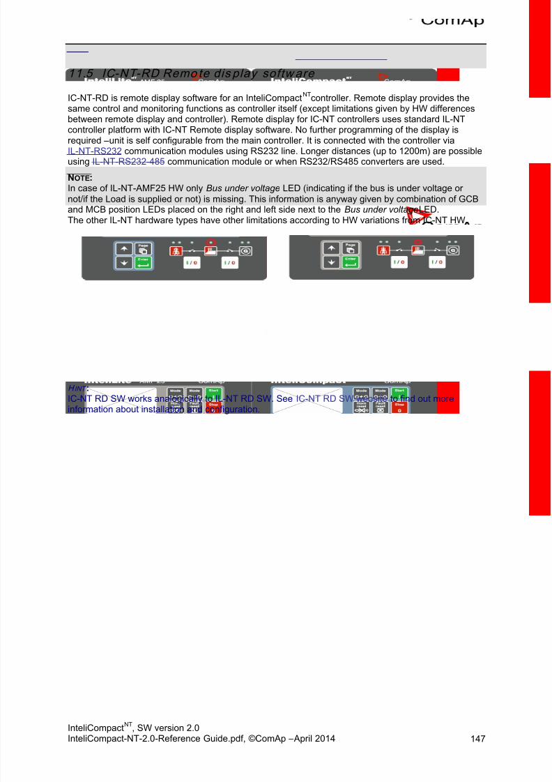
8/15/2019 InteliCompact NT 2.0 Reference Guide
http://slidepdf.com/reader/full/intelicompact-nt-20-reference-guide 147/287
InteliCompactNT
, SW version 2.0InteliCompact-NT-2.0-Reference Guide.pdf, ©ComAp – April 2014 147
11.5 IC-NT-RD Remo te dis play softw are
IC-NT-RD is remote display software for an InteliCompactNT
controller. Remote display provides thesame control and monitoring functions as controller itself (except limitations given by HW differencesbetween remote display and controller). Remote display for IC-NT controllers uses standard IL-NTcontroller platform with IC-NT Remote display software. No further programming of the display is
required – unit is self configurable from the main controller. It is connected with the controller viaIL-NT-RS232 communication modules using RS232 line. Longer distances (up to 1200m) are possibleusing IL-NT-RS232-485 communication module or when RS232/RS485 converters are used.
NOTE: In case of IL-NT-AMF25 HW only Bus under voltage LED (indicating if the bus is under voltage or
not/if the Load is supplied or not) is missing. This information is anyway given by combination of GCBand MCB position LEDs placed on the right and left side next to the Bus under voltage LED.The other IL-NT hardware types have other limitations according to HW variations from IC-NT HW.
H INT : IC-NT RD SW works analogically to IL-NT RD SW. See IC-NT RD SW website to find out more
information about installation and configuration.

8/15/2019 InteliCompact NT 2.0 Reference Guide
http://slidepdf.com/reader/full/intelicompact-nt-20-reference-guide 148/287
InteliCompactNT
, SW version 2.0InteliCompact-NT-2.0-Reference Guide.pdf, ©ComAp – April 2014 148
12 Maintenance
12.1 Backu p battery replacement
The internal backup battery lifetime is approx. 10 years. Replace the battery if the alarm LowBackupBatt occurs. Follow these instructions:
1. Connect the controller to a PC and save an archive for backup purposes.2. Disconnect all terminals from the controller and remove the controller from the switchboard.3. Release the rear cover using a flat screwdriver or other suitable tool.
4. Remove all plug-in modules.5. The battery is located in a holder on the circuit board. Remove the old battery with a small
sharp screwdriver and push the new battery into the holder with your finger. Use only aCR1225 lithium battery.

8/15/2019 InteliCompact NT 2.0 Reference Guide
http://slidepdf.com/reader/full/intelicompact-nt-20-reference-guide 149/287
InteliCompactNT
, SW version 2.0InteliCompact-NT-2.0-Reference Guide.pdf, ©ComAp – April 2014 149
6. Put the rear cover back. Use slight pressure to lock the snaps into the housing. Ensure thatthe cover is in the correct position and not upside down!
7. Plug the modules back into the slots.8. Power the controller on, adjust the date and time and check all setpoints.
NOTE: When the internal RTC battery is drained, the InteliCompact
NT function (e.g. Ready for standby) does
not change until the controller power supply is switched off. After the next power switch on (withdrained battery already), the controller will:
- Stay in the INIT state (not possible to run gen-set)- All History records disappear except for the “System log: SetpointCS err” record - Time and Date values are set to zero- Statistics values are random

8/15/2019 InteliCompact NT 2.0 Reference Guide
http://slidepdf.com/reader/full/intelicompact-nt-20-reference-guide 150/287
InteliCompactNT
, SW version 2.0InteliCompact-NT-2.0-Reference Guide.pdf, ©ComAp – April 2014 150
13 Troubleshooting
S YMPTOM
The unit is dark, no display, no LEDs are lit.
CAUSE SOLUTION
There is no power on the power terminals. Check the power supply voltage.
The boot-jumper is inserted. Remove the boot-jumper .
S YMPTOM
No display, only the backlight is on.
CAUSE SOLUTION
Extremely low display contrast.
Press the PAGE button five times, then press
and hold the ENTER button and together pressand hold the UP button until display showscorrectly.
Not valid firmware in the controller. Thissituation can occur if the previous programmingof the firmware was interrupted.
Reprogram the firmware using the boot-jumper .
S YMPTOM
The unit shows “Configuration table error ” and does not work.
CAUSE SOLUTION
The controller does not contain a validconfiguration. This situation can occur ifprevious programming of the configuration wasinterrupted.
Reprogram the configuration.
S YMPTOM
The unit shows “INIT” and does not work, controller mode cannot be changed. Thissituation occurs after controller reset if the checksum of setpoints is not correct.
CAUSE SOLUTION
New firmware containing new setpoints hasbeen programmed.
Use LiteEdit online connected to the controllerto check all setpoints and correct the wrong
ones. You have to change at least one setpoint.If all setpoints are correct, change one of themback to the original value to recalculate thechecksum. Then use the LiteEdit command
Controller -> Reset from init state.
The RTC backup battery is empty.
Replace the battery as described in theMaintenance chapter. Then proceed withLiteEdit as described in the previous situation. An alternative way is checking all setpoints fromthe front panel. Change at least one of themand then switch the controller off and on.
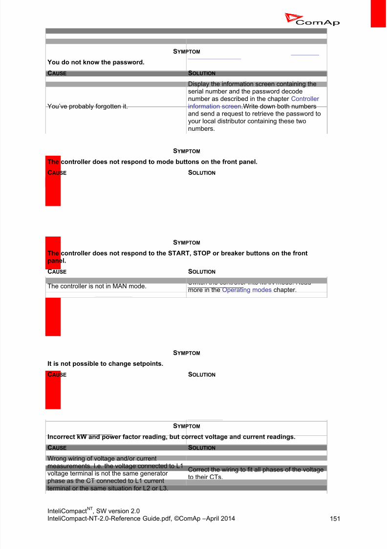
8/15/2019 InteliCompact NT 2.0 Reference Guide
http://slidepdf.com/reader/full/intelicompact-nt-20-reference-guide 151/287
InteliCompactNT
, SW version 2.0InteliCompact-NT-2.0-Reference Guide.pdf, ©ComAp – April 2014 151
S YMPTOM
You do not know the password.
CAUSE SOLUTION
You’ve probably forgotten it.
Display the information screen containing theserial number and the password decodenumber as described in the chapter Controllerinformation screen. Write down both numbersand send a request to retrieve the password toyour local distributor containing these twonumbers.
S YMPTOM
The controller does not respond to mode buttons on the front panel.
CAUSE SOLUTION
The mode is forced by one of remote mode
inputs.
Deactivate all remote mode inputs to be able to
change the mode from the front panel.The input Access Lock is active. Deactivate the input.
The setpoint ControllerMode is password-protected.
Enter the password prior to changing the mode.
S YMPTOM
The controller does not respond to the START, STOP or breaker buttons on the frontpanel.
CAUSE SOLUTION
The controller is not in MAN mode.
Switch the controller into MAN mode. Read
more in the Operating modes chapter.
The conditions needed for start or for closing ofthe breakers are not fulfilled.
The gen-set cannot be started if any red alarmis active. The GCB cannot be closed until thegen-set is running and the generator voltageand frequency are within limits. More in theStabilization chapter.
S YMPTOM
It is not possible to change setpoints.
CAUSE SOLUTION
Some setpoints can be configured as protectedby password.
Enter the password prior going to changeprotected setpoints
The binary input Access Lock is active. Switch the Access lock off.
S YMPTOM
Incorrect kW and power factor reading, but correct voltage and current readings.
CAUSE SOLUTION
Wrong wiring of voltage and/or currentmeasurements. I.e. the voltage connected to L1voltage terminal is not the same generator
phase as the CT connected to L1 currentterminal or the same situation for L2 or L3.
Correct the wiring to fit all phases of the voltageto their CTs.

8/15/2019 InteliCompact NT 2.0 Reference Guide
http://slidepdf.com/reader/full/intelicompact-nt-20-reference-guide 152/287
InteliCompactNT
, SW version 2.0InteliCompact-NT-2.0-Reference Guide.pdf, ©ComAp – April 2014 152
S YMPTOM
Governor output does not work; the output level is continuously at the lower or upperlimit.
CAUSE SOLUTION
Wrong (opposite) position of the setpoint SpeedGov Char .
Check the setpoint position if it fits the Governor requirements.
Opposite or wrong wiring of the Governor/AVRioutput.
Check and correct the wiring.
The governor output is switched to PWM modebut the governor needs voltage mode or viceversa.
Put the PWM jumper at the governor output intothe proper position according to the Governor requirements.
S YMPTOM
The cranking is cut off too early, the engine does not start.
CAUSE SOLUTION
The setpoint Starting Oil P is adjusted too low.
Adjust the setpoint to a higher pressure levelthan can be achieved by cranking only. Note,that under cold condition the oil pressureachieved during cranking can be higher.
W terminal is connected to the pickup input ofthe controller, but autodetection of frequency-to-speed ratio was not performed (e.g. if thecontroller was previously used with anotherengine with another charging alternator).
Disconnect the W terminal from the pickupinput, then start the gen-set in manual modeand wait until the gen-set is ready to take theload. Then stop the engine and connect the Wterminal back. The autodetection process willbe performed during next start.
S YMPTOM
The MCB control does not work properly, the alarm MCB fail is present all the time.
CAUSE SOLUTION
The position of the setpoint MCB Logic does notmatch the current MCB wiring.
Switch the setpoint MCB Logic into properposition.
S YMPTOM
The communication via CAN bus with other engines, extension units or ECU does notwork, i.e. you do not see other engines in the CAN16 or CAN32 value or the controllershows an alarm in the Alarmlist that some of extension units or ECU does not
communicate.
CAUSE SOLUTION
The wiring of the CAN bus network is notprovided as linear bus without nodes.
Correct the wiring as described in the chapterCAN bus wiring.

8/15/2019 InteliCompact NT 2.0 Reference Guide
http://slidepdf.com/reader/full/intelicompact-nt-20-reference-guide 153/287
InteliCompactNT
, SW version 2.0InteliCompact-NT-2.0-Reference Guide.pdf, ©ComAp – April 2014 153
14 Technical data
14.1 Power sup ply
Power supply range 8 –36 V DC
Power supply drop-outimmunity
50ms (from min. 10 V)
Power consumption approx. 200 mA / 8 V; 50 mA / 36 V
Peak power consumption(LT)
approx. 0.56 A / 8 V; 1.8 A / 36 V
Backup battery type CR 1225
Estimated backup batterylifetime
10 years
14.2 Operat ing con dit ion s
Operating temperature -20 –70 °C
Operating temperature (LTversion)
-40 –70 °C
Operating humidity 95% non-condensing (IEC/EN 60068-2-30)
Protection degree (front
panel)
IP65
Vibration 5-25 Hz, +/- 1.6 mm; 25-100 Hz, a = 4 g
Shocks amax 200 m/s
Storage temperature -30 –80 °C
14.3 Physic al dimension s
Dimensions 185x125x60 mm (WxHxD)
Weight
Mounting cutout size 175x115 mm (WxH)
14.4 Standard con form ity
Electromagneticcompatibility
EN 61000-6-1, EN 61000-6-2, EN 61000-6-3, EN 61000-6-4
Low voltage directive EN 61010-1:95 +A1:97

8/15/2019 InteliCompact NT 2.0 Reference Guide
http://slidepdf.com/reader/full/intelicompact-nt-20-reference-guide 154/287
InteliCompactNT
, SW version 2.0InteliCompact-NT-2.0-Reference Guide.pdf, ©ComAp – April 2014 154
14.5 Binary inpu ts
Number of binary inputs 9
Galvanic insulation Not insulated
Common pole Positive, Vs = 8 –36 V DC
Closed contact voltage <2 V
Open contact voltage 4 V - Vs
Input resistance 4.2 kΩ
14.6 Binary outp uts
Number of binary outputs 8
Galvanic insulation Not insulated
Type Transistor, switching to negative supply terminal
Operating voltage 8 –36 V DC
Switching current 500 mA (suppression diodes required for inductive loads)
Total current 2 A (overall current for all binary outputs)
14.7 Analog inpu ts
Number of analog inputs 3
Galvanic insulation Not insulated
Electrical range 0 –2500 Ω
Resolution 10 bits, 4 digits
Supported sensor typesPredefined: VDO 10Bar, VDO Temperature, VDO Fuel levelUser-defined: 10 points non-linear sensors can be defined by theuser
Precision 1% from the range
14.8 Generator/Mains measurements
Measurement inputs 3ph generator voltage, 3ph generator current, 3ph mains voltage
Measurement type True RMS
Voltage range 480 V Ph-Ph (277 V Ph-N)
Max. measured voltage 340 V Ph-N
Voltage accuracy 1% from the range
Current range 5 A
Max. measured current 9 A
Max. allowed current 12 A continuous, 50 A/1
Current accuracy 2% from the range

8/15/2019 InteliCompact NT 2.0 Reference Guide
http://slidepdf.com/reader/full/intelicompact-nt-20-reference-guide 155/287
InteliCompactNT
, SW version 2.0InteliCompact-NT-2.0-Reference Guide.pdf, ©ComAp – April 2014 155
CT input burden <0.5 VA
Frequency range 30-70 Hz, measured from L3
Frequency accuracy 0.05 Hz
14.9 Pickup inpu t
Input voltage 2 –70 Vpp
Frequency range 4 Hz –10 kHz (min 2 Vpp @ 4 kHz, 6 V pp @ 10 kHz)
Accuracy 0.2%
14.10 Charging alternator pre-excitat ion circu it
Excitation current 200 mA, during the engine start only
Charging fail threshold 80% of Usupply
14.11 AVR ou tpu t
Output type 5 V PWM, designed for IG-AVRi interface module
Galvanic insulation Not insulated, insulation is provided by IG-AVRi module
14.11.1 IG-AVRi module
Power supply 18 V AC from IG-AVRi Trans/LV or IG-AVRi Trans/100
Max. power supply range 15 –25 V AC or 20 –35V DC
Inputs -AVR, -AVR (two wires, PWM from IC-NT)
Outputs OUT1, OUT2 floating (potential free) voltage source
AVRi output voltage range Potentiometer adjustable from ±1 V to ±10 V DC
AVRi output current max 15 mA
Mechanical dimensions 96 x 27 x 43 mm, DIN rail (35 mm) mounted
14.11.2 IG-AVRi Trans/LV
Primary voltage 1 230 –277 V AC
Absolute low limit 1 230 V AC – 20%
Absolute high limit 1 277 V AC + 20%
Primary voltage 2 400 –480 V AC
Absolute low limit 2 400 V AC – 20%
Absolute high limit 2 480 V AC + 20%
Frequency 50 –60 Hz
Secondary voltage 18 V AC, 5 VA

8/15/2019 InteliCompact NT 2.0 Reference Guide
http://slidepdf.com/reader/full/intelicompact-nt-20-reference-guide 156/287

8/15/2019 InteliCompact NT 2.0 Reference Guide
http://slidepdf.com/reader/full/intelicompact-nt-20-reference-guide 157/287
InteliCompactNT
, SW version 2.0InteliCompact-NT-2.0-Reference Guide.pdf, ©ComAp – April 2014 157
Termination resistor 120 Ω, built-in, jumper activated
14.15.1 Recommended CAN cables
Belden 3082A DeviceBus for Allen-Bradley DeviceNet Belden 3083A DeviceBus for Allen-Bradley DeviceNet
Belden 3084A DeviceBus for Allen-Bradley DeviceNet
Belden 3085A DeviceBus for Allen-Bradley DeviceNet
Belden 3086A DeviceBus for Honeywell SDS
Belden 3087A DeviceBus for Honeywell SDS
Lapp Cable Unitronic Bus DeviceNet Trunk Cable
Lapp Cable Unitronic Bus DeviceNet Drop Cable
Lapp Cable Unitronic Bus CAN
Lapp Cable Unitronic-FD Bus P CAN UL/CSA

8/15/2019 InteliCompact NT 2.0 Reference Guide
http://slidepdf.com/reader/full/intelicompact-nt-20-reference-guide 158/287
InteliCompactNT
, SW version 2.0InteliCompact-NT-2.0-Reference Guide.pdf, ©ComAp – April 2014 158
15 Language support
The controller contains memory slots for 2 languages. English and Chinese are provided in the default
archives. The languages can be changed in the LiteEdit software using dictionaries. There are twotypes of dictionaries:
Default dictionaries are distributed together with the controller firmware.
Custom dictionaries are created by the user during the translation process.
The custom dictionary is used for storing translations that were made by the user because there wasno default dictionary for the particular language, the default dictionary was incomplete or the usersimply wishes to have different translations. For more information about languages and translations,see the LiteEdit help.
It is possible to create any language using a code page supported by the controller:
Win 1250 – Middle Europe Win 1251 – Eastern Europe (Cyrillic)
Win 1252 – Western Europe, America
Win 1254 – Turkish
GB2312 – Chinese
NOTE: See the Operator guide for information on how to select the controller front panel language.

8/15/2019 InteliCompact NT 2.0 Reference Guide
http://slidepdf.com/reader/full/intelicompact-nt-20-reference-guide 159/287
InteliCompactNT
, SW version 2.0InteliCompact-NT-2.0-Reference Guide.pdf, ©ComAp – April 2014 159
16 Appendix
16.1 Table of setpo ints
16.1.1 Group: Process Control
Setpoint: Baseload16.1.1.1
Group Process Control
Range [units] 0 … Nominal power [kW]
Relatedapplications
SPtM
Description Required gen-set load in parallel to mains operation.
Setpoint: Base PF16.1.1.2
Group Process Control
Range [units] 0.7 ... 1.0 [-]
Relatedapplications
SPtM
Description Required gen-set power factor when the gen-set is running parallel to themains.
Setpoint: AMFStartEnable16.1.1.3
Group Process Control
Range [units] NO, YES [-]
Relatedapplications
SPtM
Description Use this setpoint to enable or disable the AMF operation.
Setpoint: Export Limit16.1.1.4
Group ProcessControl
Range [units] DISABLED, ENABLED [-]
Relatedapplications
SPtM
Description Tells controller to activate protection against power export to the Mains. Thefunction limits gen-set requested power to hold export power lower or equalto the setpoint Export kW .

8/15/2019 InteliCompact NT 2.0 Reference Guide
http://slidepdf.com/reader/full/intelicompact-nt-20-reference-guide 160/287
InteliCompactNT
, SW version 2.0InteliCompact-NT-2.0-Reference Guide.pdf, ©ComAp – April 2014 160
Setpoint: Export kW16.1.1.5
Group ProcessControl
Range [units] -32000 … 32000 [kW]
Relatedapplications
SPtM
Description Defines max limit for export/import in case Export Limit setpoint is set toENABLED. A negative value means import limit, a positive value export limit,zero means no export/import.
Setpoint: #SysLdCtrl PtM16.1.1.6
Group Process Control
Range [units] BASELOAD, LDSHARING [-]
Relatedapplications
MINT
Description Load control mode in parallel to mains operation of the whole group of gen-sets.
BASELOAD: The total power of the group is controlled to constant levelgiven by the setpoint #SysBaseLoad . Each loaded gen-set takes equal part(relative to their nominal power) from this requested value. The load isregulated locally in each controller by Load control regulation loop, load-sharing is not active. The setpoint #Sys base load is also used for
determining which gen-sets have to run or not.
LDSHARING: Gen-sets load is controlled by MainsCompact controller to
share the total load (given by the setpoint #SysBaseLoad ) with other loadedgen-sets in such a way, that all loaded gen-sets will be loaded at the samelevel (relative to gen-set nominal power). Load-sharing regulation loop is
active.
NOTE: The LOADSHARING mode shall be used in case a MainsCompact controlleris present in the system. In systems without MainsCompact the setpoint mustbe in the BASELOAD position.
NOTE: The power factor (PF) is regulated to constant level given by the setpoint#SysPwrFactor in parallel to mains operation and does not depend on active
load control mode.
Setpoint: #SysBaseLoad16.1.1.7
Group Process Control
Range [units] 0 ... 4000 [kW]
Relatedapplications
MINT
Description Required total load of the gen-set group in parallel to mains operation inbaseload mode (setpoint #SysLdCtrl PtM = BASELOAD).

8/15/2019 InteliCompact NT 2.0 Reference Guide
http://slidepdf.com/reader/full/intelicompact-nt-20-reference-guide 161/287
InteliCompactNT
, SW version 2.0InteliCompact-NT-2.0-Reference Guide.pdf, ©ComAp – April 2014 161
Setpoint: #SysPwrFactor16.1.1.8
Group Process Control
Range [units] 0.7 ... 1.0 [-]
Related
applications
MINT
Description Required gen-set power factor when the group of gen-sets is running parallelto the mains. The PF is regulated locally in each controller by PF control regulation loop, VARsharing is not active.
Setpoint: Synchro Enable16.1.1.9
Group ProcessControl
Range [units] NONE, FORWARD, REVERSE, BOTH [-]
Relatedapplications All
Description Enables or disables forward/reverse synchronization (according to SPtM /MINT versions).
NONE No synchronizing is enabled. (SPtM and MINT)
FORWARD GCB synchronizing is enabled. (SPtM and MINT)
REVERSE MCB synchronizing is enabled. (SPtM)
BOTH GCB and MCB synchronizing are enabled. (SPtM)
Setpoint: PeakLevelStart16.1.1.10
Group Process Control
Range [units] PeakLevelStop ... 32000 [kW]
Relatedapplications
SPtM
Description Load consumption level the gen-set has to start at. Function is inactive whenPeakAutS/S Del = OFF. Gen-set start is “PeakAutS/S Del” delayed after theconsumption of the Load exceeds the PeakLevelStart limit.
NOTE:
The actual setpoint units and range depend on setting of the Power format(see the LiteEdit manual).
NOTE:It is necessary to use IC-NT CT-BIO7 module and measure 1Ph Mainscurrent.

8/15/2019 InteliCompact NT 2.0 Reference Guide
http://slidepdf.com/reader/full/intelicompact-nt-20-reference-guide 162/287
InteliCompactNT
, SW version 2.0InteliCompact-NT-2.0-Reference Guide.pdf, ©ComAp – April 2014 162
Setpoint: PeakLevelStop16.1.1.11
Group Process Control
Range [units] 0 ... PeakLevelStart [kW]
Related
applications
SPtM
Description Load consumption level the gen-set has to stop at. Gen-set stop is“PeakAutS/S Del ” delayed after PeakLevelStop limit is reached. Loadconsumption is calculated (not directly measured) as a sum of gen-set andmains active power.
NOTE: The actual setpoint units and range depend on setting of the Power format(see LiteEdit manual).
NOTE:It is necessary to use IC-NT CT-BIO7 module and measure 1Ph Mainscurrent.
Setpoint: PeakAutS/S del16.1.1.12
Group Process Control
Range [units] 0 (OFF) ... 600 [s]
Relatedapplications
SPtM
Description The condition for the “peak” automatic start or stop must be valid for a periodlonger than the value of this setpoint to execute the automatic start or stop. Adjusting to “0” causes stop of the gen-set (if there is no other demand for
running) and disables the automatic peak shaving start.

8/15/2019 InteliCompact NT 2.0 Reference Guide
http://slidepdf.com/reader/full/intelicompact-nt-20-reference-guide 163/287
InteliCompactNT
, SW version 2.0InteliCompact-NT-2.0-Reference Guide.pdf, ©ComAp – April 2014 163
Setpoint: #Neutral cont16.1.1.13
Group Process Control
Range [units] EACH, COMMON [-]
Related
applications
SPtM
Description Setpoint changes behaviour of binary output Neutral CB C/O which is usedfor Neutral contactor control.
EACH:
- When GCB is opened (after start, before stop):o Neutral contactor closes when Generator voltage is higher than
85% of Nominal voltage.o Neutral contactor opens when Generator voltage is lower than
50% of Nominal voltage.- When multiple gen-sets are connected to the bus and MCB is opened
(island running group) the Neutral contactor is closed on the running gen-set with the lowest Contr. address only. When a lower controller address
gen-set is connected to the bus, the Neutral contactor connectionchanges.
- Neutral contactor is opened when gen-sets are running in parallel to themains.
COMMON:- When MCB is opened Neutral contactor closes when at least one
Generator voltage from the group (at least one phase) is higher than 86%of Nominal voltage.
- When MCB is opened, the Neutral contactor opens when all phases of allgen-set voltages are lower than 50% of Nominal voltage.
- When MCB is closed, the Neutral contactor opens.
NOTE:
Configure BO: Neutral CB C/O and BI: NeutralCB fdb prior to Neutralcontactor function is used.
16.1.2 Group: Basic Settings
Setpoint: ControllerName16.1.2.1
Group Basic Settings
Range [units] [-]
Related
applications
All
Description User-defined name, used for controller identification at remote connections.The name can be max. 15 characters long and must be entered usingLiteEdit.
NOTE: The setpoint can't be changed from the front panel of the controller.
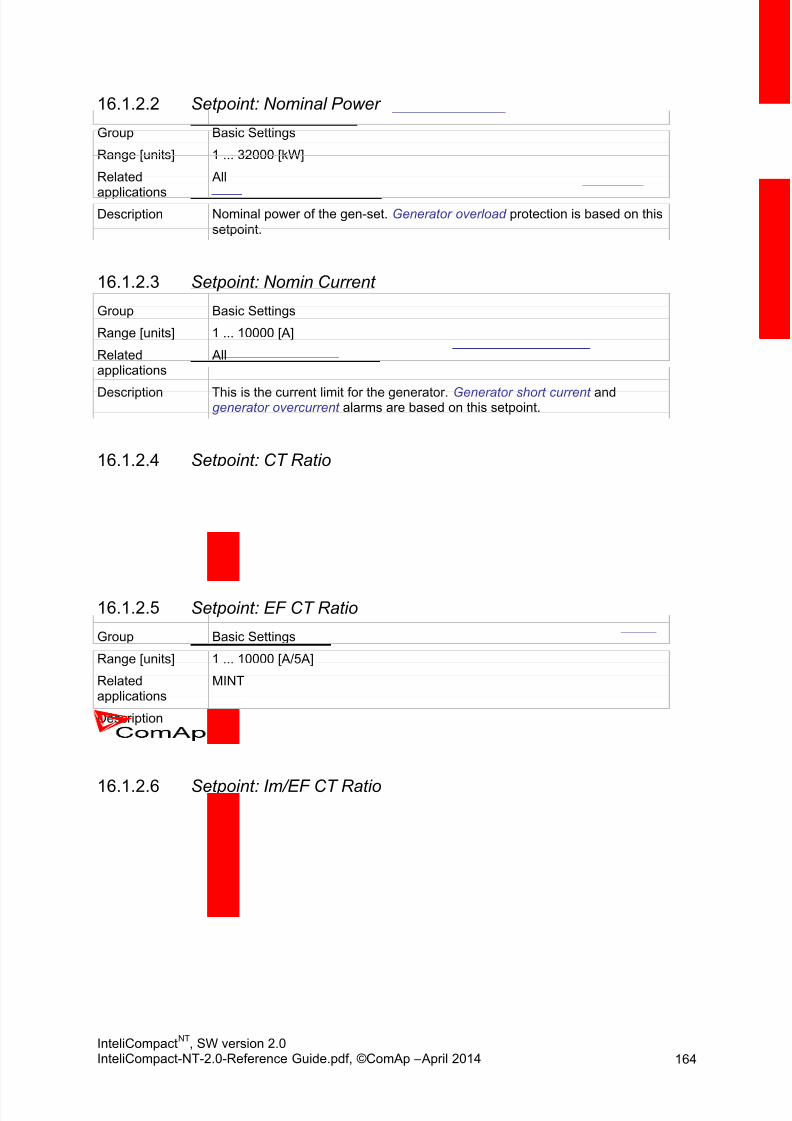
8/15/2019 InteliCompact NT 2.0 Reference Guide
http://slidepdf.com/reader/full/intelicompact-nt-20-reference-guide 164/287
InteliCompactNT
, SW version 2.0InteliCompact-NT-2.0-Reference Guide.pdf, ©ComAp – April 2014 164
Setpoint: Nominal Power16.1.2.2
Group Basic Settings
Range [units] 1 ... 32000 [kW]
Related
applications
All
Description Nominal power of the gen-set. Generator overload protection is based on this
setpoint.
Setpoint: Nomin Current16.1.2.3
Group Basic Settings
Range [units] 1 ... 10000 [A]
Relatedapplications
All
Description This is the current limit for the generator. Generator short current andgenerator overcurrent alarms are based on this setpoint.
Setpoint: CT Ratio16.1.2.4
Group Basic Settings
Range [units] 1 ... 10000 [A/5A]
Relatedapplications
All
Description Gen-set current transformers ratio.
Setpoint: EF CT Ratio16.1.2.5
Group Basic Settings
Range [units] 1 ... 10000 [A/5A]
Relatedapplications
MINT
Description Defines current transformer ratio for current measuring input of IC-NT CT-BIO7 extension module if used.
Setpoint: Im/EF CT Ratio16.1.2.6
Group Basic Settings
Range [units] 1 ... 10000 [A/5A]
Relatedapplications
SPtM
Description Defines mains current transformer ratio for current measuring input of IC-NTCT-BIO7 extension module if used.
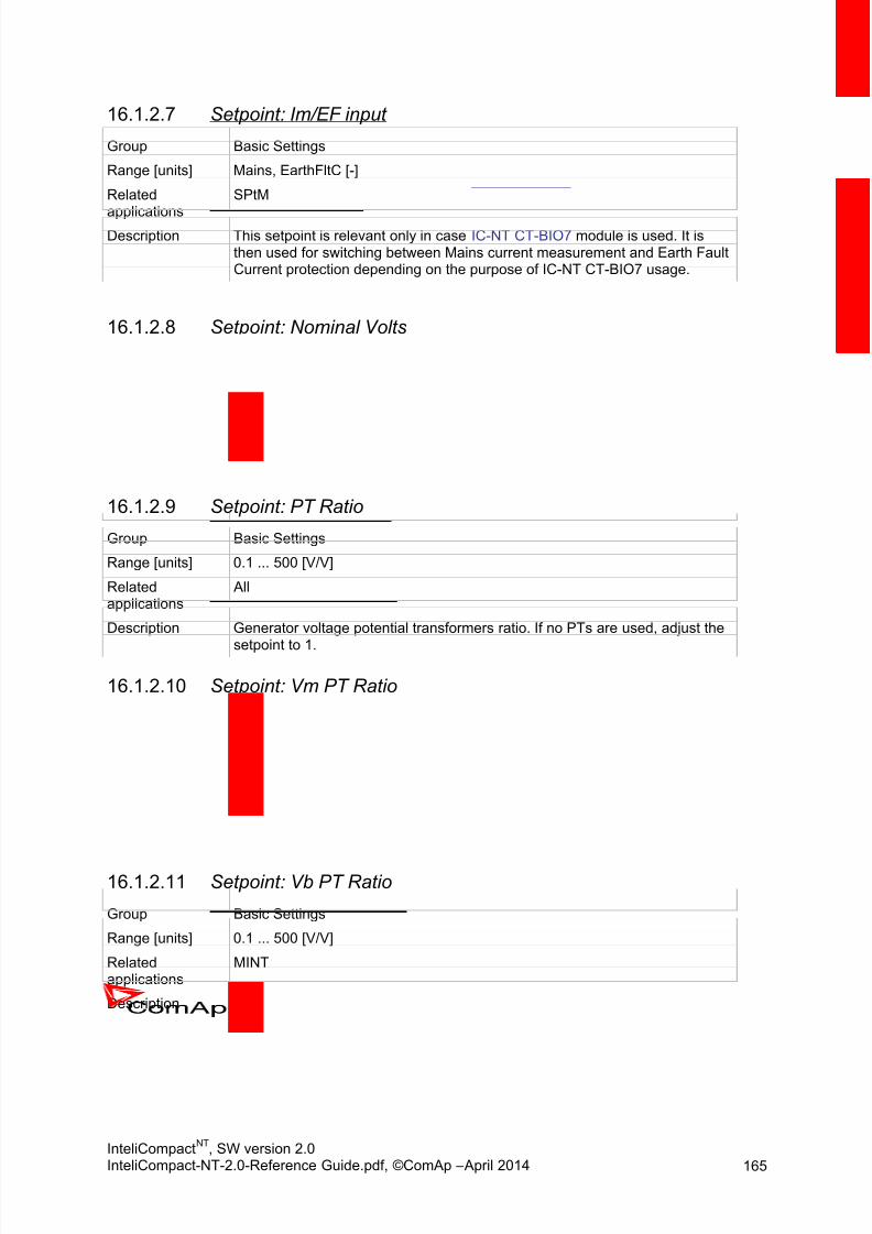
8/15/2019 InteliCompact NT 2.0 Reference Guide
http://slidepdf.com/reader/full/intelicompact-nt-20-reference-guide 165/287
InteliCompactNT
, SW version 2.0InteliCompact-NT-2.0-Reference Guide.pdf, ©ComAp – April 2014 165
Setpoint: Im/EF input16.1.2.7
Group Basic Settings
Range [units] Mains, EarthFltC [-]
Related
applications
SPtM
Description This setpoint is relevant only in case IC-NT CT-BIO7 module is used. It isthen used for switching between Mains current measurement and Earth FaultCurrent protection depending on the purpose of IC-NT CT-BIO7 usage.
Setpoint: Nominal Volts16.1.2.8
Group Basic Settings
Range [units] 80 ... 20000 [V]
Relatedapplications
All
Description Nominal system voltage (phase to neutral)
Setpoint: PT Ratio16.1.2.9
Group Basic Settings
Range [units] 0.1 ... 500 [V/V]
Relatedapplications
All
Description Generator voltage potential transformers ratio. If no PTs are used, adjust the
setpoint to 1.
Setpoint: Vm PT Ratio16.1.2.10
Group Basic Settings
Range [units] 0.1 ... 500 [V/V]
Relatedapplications
SPtM
Description Mains voltage potential transformers ratio. If no PTs are used, adjust thesetpoint to 1.
Setpoint: Vb PT Ratio16.1.2.11
Group Basic Settings
Range [units] 0.1 ... 500 [V/V]
Relatedapplications
MINT
Description Bus voltage potential transformers ratio. If no PTs are used, adjust thesetpoint to 1.

8/15/2019 InteliCompact NT 2.0 Reference Guide
http://slidepdf.com/reader/full/intelicompact-nt-20-reference-guide 166/287
InteliCompactNT
, SW version 2.0InteliCompact-NT-2.0-Reference Guide.pdf, ©ComAp – April 2014 166
Setpoint: Nominal Freq16.1.2.12
Group Basic Settings
Range [units] 45 ... 65 [Hz]
Related
applications
All
Description Nominal system frequency (usually 50 or 60Hz).
Setpoint: Nominal RPM16.1.2.13
Group Basic Settings
Range [units] 100 ... 4000 [RPM]
Relatedapplications
All
Description Nominal engine speed.
Setpoint: Gear Teeth16.1.2.14
Group Basic Settings
Range [units] 0 (OFF) ... 500 [-]
Relatedapplications
All
Description Number of teeth on the engine flywheel where the pick-up is installed. Set tozero if no pick-up is used and the Engine speed will be counted from thegenerator frequency.
NOTE: If no pickup is used, the D+ or W terminal should be used to prevent possibleovercranking, which can occur if at least 25% of nominal generator voltage isnot present immediately after exceeding firing speed.
Setpoint: ControllerMode16.1.2.15
Group Basic Settings
Range [units] OFF, MAN, AUT, (TEST) [-]
Relatedapplications
All
Description This setpoint can be used for changing the operating mode remotely, e.g. viaModbus. Use the mode selector on the main screen for changing the modefrom the front panel. Use mode selector in the control window for changingthe mode from LiteEdit.

8/15/2019 InteliCompact NT 2.0 Reference Guide
http://slidepdf.com/reader/full/intelicompact-nt-20-reference-guide 167/287
InteliCompactNT
, SW version 2.0InteliCompact-NT-2.0-Reference Guide.pdf, ©ComAp – April 2014 167
Setpoint: Reset To MAN16.1.2.16
Group Basic Settings
Range [units] DISABLED, ENABLED [-]
Related
applications
All
Description If this function is enabled, the controller will switch automatically to MANmode when there is a red alarm in the alarm list and fault reset is pressed.This is a safety function that prevents the gen-set starting again automaticallyif the gen-set is stopped due to a red alarm, the alarm is no longer active andfault reset is pressed.
Setpoint: Backlight time16.1.2.17
Group Basic Settings
Range [units] 0 – 240 [min]
Relatedapplications
MINT
Description Function will switch off the screen backlight after preset number of minutes.Pressing any button on the controller or automatic start of the gen-set (e.g.due to power management) will switch the backlight back on.Default value is 15 minutes. It is possible to switch the function off by setting0 (backlight will be on all the time).
16.1.3 Group: Comms Settings
Setpoint: ControllerAddr16.1.3.1Group Comms Settings
Range [units] 1 ... 32(8) [-]
Relatedapplications
All
Description Unique identification number of a controller within a group of controllers
which are connected together via CAN2 bus (MINT, MC) or RS485 bus(SPtM).
NOTE: Adjust the controller address to 1 if you have SPtM application and no other
controllers are connected to the RS485 bus.
NOTE: Do not use the same address for multiple controllers in the same group!
NOTE: Use the proper address when connecting to the controller from LiteEdit.
NOTE: Changing the address remotely (e.g. from LiteEdit) will cause connectionloss!

8/15/2019 InteliCompact NT 2.0 Reference Guide
http://slidepdf.com/reader/full/intelicompact-nt-20-reference-guide 168/287
InteliCompactNT
, SW version 2.0InteliCompact-NT-2.0-Reference Guide.pdf, ©ComAp – April 2014 168
Setpoint: COM1 Mode16.1.3.2
Group Comms Settings
Range [units] DIRECT, MODEM, MODBUS, ECU LINK [-]
Related
applications
All
Description Communication protocol switch for the COM1 channel.
DIRECT: ComAp PC SW communication protocol via direct cable.
MODEM: ComAp PC SW communication protocol via modem.
MODBUS: Modbus protocol. Find a detailed description in a separatechapter.
ECU LINK: Protocol for communication with EFI engines via Modbus.
Setpoint: COM2 Mode16.1.3.3
Group Comms Settings
Range [units] DIRECT, MODBUS, ECU LINK [-]
Relatedapplications
All
Description Communication protocol switch for the COM2 channel.
DIRECT: ComAp PC SW communication protocol via direct cable.
MODBUS: Modbus protocol. Find a detailed description in a separatechapter.
ECU LINK: Protocol for communication with EFI engines via Modbus.
Setpoint: ModemIniString16.1.3.4
Group Comms Settings
Range [units] [-]
Relatedapplications
All
Description If your modem needs additional initialization AT commands (i.e. because ofnational telephony network differences), they can be entered here. Otherwiseleave this setpoint blank.
Setpoint: ModbusComSpeed16.1.3.5
Group Comms Settings
Range [units] 9600, 19200, 38400, 57600 [bps]
Relatedapplications
All
Description If the Modbus mode is selected on COM1 or COM2 channels, the Modbuscommunication speed can be adjusted here.

8/15/2019 InteliCompact NT 2.0 Reference Guide
http://slidepdf.com/reader/full/intelicompact-nt-20-reference-guide 169/287
InteliCompactNT
, SW version 2.0InteliCompact-NT-2.0-Reference Guide.pdf, ©ComAp – April 2014 169
Setpoint: CAN Bus Mode16.1.3.6
Group Comms Settings
Range [units] 32C, 8C [-]
Related
applications
MINT
Description CAN bus speed selection.
32C: High speed CAN (250 kbps) applicable for up to 32 controllers,CAN bus length limited to 200 meters.
8C: Low speed CAN (50 kbps) applicable for up to 8 controllers, CANbus length limited to 900 meters.
NOTE: Use low speed for a long-distance connection only. Set all connectedcontrollers to the same speed.
Setpoint: IBLite IP Addr16.1.3.7
Group Comms Settings
Range [units] [-]
Relatedapplications
All
Description If DHCP is DISABLED this setpoint is used to adjust the IP address of theEthernet interface of the controller. Ask your IT specialist for help with thissetting.
If DHCP is ENABLED this setpoint is used to display the IP address, which
has been assigned by the DHCP server.
Setpoint: IBLite NetMask16.1.3.8
Group Comms Settings
Range [units] [-]
Relatedapplications
All
Description If DHCP is DISABLED this setpoint is used to adjust the IP address of theEthernet interface of the controller. Ask your IT specialist for help with this
setting.If DHCP is ENABLED this setpoint is used to display the IP address, whichhas been assigned by the DHCP server.
Setpoint: IBLite GateIP16.1.3.9
Group Comms Settings
Range [units] [-]
Relatedapplications
All
Description If DHCP is DISABLED this setpoint is used to adjust the IP address of thegateway of the network segment where the controller is connected.

8/15/2019 InteliCompact NT 2.0 Reference Guide
http://slidepdf.com/reader/full/intelicompact-nt-20-reference-guide 170/287

8/15/2019 InteliCompact NT 2.0 Reference Guide
http://slidepdf.com/reader/full/intelicompact-nt-20-reference-guide 171/287
InteliCompactNT
, SW version 2.0InteliCompact-NT-2.0-Reference Guide.pdf, ©ComAp – April 2014 171
Setpoint: APN UserName16.1.3.13
Group Comms Settings
Range [units] [-]
Related
applications
All
Description User name for APN access point provided by GSM/GPRS operator.
Setpoint: APN UserPass16.1.3.14
Group Comms Settings
Range [units] [-]
Relatedapplications
All
Description User password for APN access point provided by GSM/GPRS operator.
Setpoint: AirGate16.1.3.15
Group Comms Settings
Range [units] DISABLED / ENABLED [-]
Relatedapplications
All
Description This setpoint selects the Ethernet connection mode.
DISABLED:
This is a standard mode in which the controller listens to the incoming trafficand answers the TCP/IP queries addressed to it. This mode requires thecontroller to be accessible from the remote device (PC), i.e. it must beaccessible at a public and static IP address if you want to connect to it fromthe internet.
ENABLED:
This mode uses the “ AirGate” service, which hides all issues with static/publicaddress in a black box and you do not need to do anything about it. You needonly a connection to the Internet. The AirGate server address is adjusted bythe setpoint AirGate IP .
Setpoint: AirGate IP16.1.3.16
Group Comms Settings
Range [units] [-]
Relatedapplications
All
Description This setpoint is used for entering the domain name or IP address of the AirGate server. Use the free AirGate server provided by ComAp atairgate.comap.cz if your company does not operate its own AirGate server.

8/15/2019 InteliCompact NT 2.0 Reference Guide
http://slidepdf.com/reader/full/intelicompact-nt-20-reference-guide 172/287
InteliCompactNT
, SW version 2.0InteliCompact-NT-2.0-Reference Guide.pdf, ©ComAp – April 2014 172
Setpoint: SMTP UserName16.1.3.17
Group Comms Settings
Range [units] [-]
Related
applications
All
Description Use this setpoint to enter the username for the SMTP server.
Setpoint: SMTP UserPass16.1.3.18
Group Comms Settings
Range [units] [-]
Relatedapplications
All
Description Use this setpoint to enter the password for the SMTP server.
Setpoint: SMTP Server IP16.1.3.19
Group Comms Settings
Range [units] [-]
Relatedapplications
All
Description This setpoint is used for entering the domain name (e.g.smtp.yourprovider.com) or IP address (e.g. 74.125.39.109) of the SMTPserver. Ask your internet provider or IT manager for this information.
H INT : You may also use one of the free SMTP servers, e.g. smtp.gmail.com.However, note that some free SMTP servers may cause delays (up to severalhours) when sending e-mails.
If you do not want to send active e-mails, you may leave this setpoint blank,as well as other setpoints related to SMTP server and e-mail settings.
Proper setting of SMTP-related setpoints as well as the controller mailbox areessential for sending alerts via e-mails
Setpoint: Contr MailBox16.1.3.20Group Comms Settings
Range [units] [-]
Relatedapplications
All
Description Enter an existing e-mail address in this setpoint. This address will be used asthe sender address in active e-mails that will be sent from the controller.

8/15/2019 InteliCompact NT 2.0 Reference Guide
http://slidepdf.com/reader/full/intelicompact-nt-20-reference-guide 173/287
InteliCompactNT
, SW version 2.0InteliCompact-NT-2.0-Reference Guide.pdf, ©ComAp – April 2014 173
Setpoint: Time Zone16.1.3.21
Group Comms Settings
Range [units] GMT -12:00 … GMT +13:00 [-]
Related
applications
All
Description This setpoint is used to select the time zone where the controller is located.Refer to your computer time zone settings (click on the time indicator locatedin the rightmost position of the Windows task bar) if you are not sure aboutyour time zone.
H INT : If the time zone is not selected properly the active e-mails may containincorrect information about the time they were sent, which may result inconfusion about when the respective problem actually occurred.
Setpoint: DNS IP Address16.1.3.22
Group Comms Settings
Range [units] [-]
Relatedapplications
All
Description If DHCP is DISABLED this setpoint is used to adjust the domain name server(DNS), which is needed to translate domain names in e-mail addresses andserver names into correct IP addresses.
If DHCP is ENABLED this setpoint is used to display the DNS server
assigned by the DHCP server.
16.1.4 Group: Engine Params
Setpoint: Starting RPM16.1.4.1
Group Engine Params
Range [units] 5 ... 50 [%]
Related
applications
All
Description This setpoint defines the “firing” speed level as percent value of the nominalspeed. If this level is exceeded the engine is considered as started. Moreinformation is available in the Engine start chapter.

8/15/2019 InteliCompact NT 2.0 Reference Guide
http://slidepdf.com/reader/full/intelicompact-nt-20-reference-guide 174/287
InteliCompactNT
, SW version 2.0InteliCompact-NT-2.0-Reference Guide.pdf, ©ComAp – April 2014 174
Setpoint: Start W Freq16.1.4.2
Group Engine Params
Range [units] 0 … 2000 [Hz]
Related
applications
All
Description This setpoint defines starter cutoff frequency, if the engine speed ismeasured from the generator frequency and the “W” terminal from thecharging alternator is connected to the pickup input. More information isavailable in the Speed measurement chapter.
NOTE: This setpoint is active only if the setpoint Gear Teeth is adjusted to zero.
Setpoint: Starting Oil P16.1.4.3
Group Engine Params
Range [units] Configuration dependent [Configuration dependent]
Relatedapplications
All
Description The controller will stop cranking (starter goes OFF) if the oil pressure risesabove this limit. See the description of the start procedure in a separatechapter .
NOTE: If an EFI engine is used, the oil pressure is read from its ECU. In the case ofa traditional engine, the analog input 1 is configured as fixed for oil pressuremeasurement.
Setpoint: Prestart Time16.1.4.4
Group Engine Params
Range [units] 0 ... 600 [s]
Relatedapplications
All
Description Duration of the closing of the Prestart output prior to the starter motor beingenergized. Set it to zero to disable this function.
Setpoint: MaxCrank Time16.1.4.5
Group Engine Params
Range [units] 1 ... 255 [s]
Relatedapplications
All
Description Maximum duration the starter motor is energized.

8/15/2019 InteliCompact NT 2.0 Reference Guide
http://slidepdf.com/reader/full/intelicompact-nt-20-reference-guide 175/287
InteliCompactNT
, SW version 2.0InteliCompact-NT-2.0-Reference Guide.pdf, ©ComAp – April 2014 175
Setpoint: CrnkFail Pause16.1.4.6
Group Engine Params
Range [units] 5 ... 60 [s]
Related
applications
All
Description Pause between crank attempts.
Setpoint: Crank Attempts16.1.4.7
Group Engine Params
Range [units] 1 ... 10 [-]
Relatedapplications
All
Description Max. number of crank attempts.
NOTE: If the last attempt is not successful, the alarm Start fail is issued.
Setpoint: Idle Time16.1.4.8
Group Engine Params
Range [units] 0 ... 600 [s]
Relatedapplications
All
Description This setpoint determines the duration of the Idle period which begins after the
engine is started. The output Idle/Nominal remains inactive during the idleperiod. This output can be used for switching the governor between idle andnominal speed.
Setpoint: Min Stab Time16.1.4.9
Group Engine Params
Range [units] 1 ... Max Stab Time [s]
Relatedapplications
All
Description When the gen-set has been started and the idle timer has elapsed, thecontroller will wait for a period adjusted by this setpoint before closing GCB orstarting synchronizing, even if the generator voltage and frequency arealready in limits.

8/15/2019 InteliCompact NT 2.0 Reference Guide
http://slidepdf.com/reader/full/intelicompact-nt-20-reference-guide 176/287
InteliCompactNT
, SW version 2.0InteliCompact-NT-2.0-Reference Guide.pdf, ©ComAp – April 2014 176
Setpoint: Max Stab Time16.1.4.10
Group Engine Params
Range [units] Min Stab Time … 300 [s]
Related
applications
All
Description When the gen-set has been started and the idle timer has elapsed, thegenerator voltage and frequency must get within limits within this period oftime, otherwise an appropriate red alarm (generator voltage and/orfrequency) is issued.
Setpoint: Cooling Speed16.1.4.11
Group Engine Params
Range [units] IDLE, NOMINAL
Relatedapplications
All
Description This setpoint selects whether the cooling phase is performed at idle ornominal speed.
Setpoint: Cooling Time16.1.4.12
Group Engine Params
Range [units] 0 ... 3600 [s]
Relatedapplications
All
Description Duration of the gen-set is running unloaded to cool the engine down beforestop.
Setpoint: Stop Time16.1.4.13
Group Engine Params
Range [units] 0 ... 240 [s]
Relatedapplications
All
Description Under normal conditions the engine must certainly stop within this periodafter the fuel solenoid has been de-energized and the stop solenoid energized. The stop solenoid remains energized for the entire stop timeperiod.
NOTE: See the chapter Cool down and stop for details about the stop procedure.

8/15/2019 InteliCompact NT 2.0 Reference Guide
http://slidepdf.com/reader/full/intelicompact-nt-20-reference-guide 177/287
InteliCompactNT
, SW version 2.0InteliCompact-NT-2.0-Reference Guide.pdf, ©ComAp – April 2014 177
Setpoint: SDVentil Time16.1.4.14
Group Engine Params
Range [units] 0 ... 60 [s]
Related
applications
All
Description In case Fuel Solenoid is set to GAS, the SDVentilTime adjusts the time of the
starter to be switched on for engine pre-ventilation in the case of a first startattempt after shutdown or controller switch-on.
Setpoint: Fuel Solenoid16.1.4.15
Group Engine Params
Range [units] DIESEL, GAS [-]
Relatedapplications
All
Description This setpoint selects the type of start-up sequence according to engine fueltype. See details in chapter Engine start.
Setpoint: D+ Function16.1.4.16
Group Engine Params
Range [units] ENABLED, CHRGFAIL, DISABLED [-]
Relatedapplications
All
Description ENABLED: The D+ terminal is used for both functions – “running engine”detection and charge fail alarm detection.
CHRGFAIL: The D+ terminal is used for charge fail alarm detection only
DISABLED: The D+ terminal is not used.
NOTE: The magnetization current is provided independent of this setpoint value.
Setpoint: ECU FreqSelect16.1.4.17
Group Engine Params
Range [units] PRIMARY, SECONDARY, DEFAULT [-]
Relatedapplications
All
Description This setpoint is used for choosing a frequency of ECU. PRIMARY is forfrequency which is set up in basic settings. SECONDARY is for frequencywhich is set up in alternative settings. DEFAULT is for frequency which is setup by producter of ECU.
VOLVO EMSII (GE engines) The nominal speed is selected via the VP Status proprietary frame,parameter “Frequency select”.
SCANIA EMS/S6
The nominal speed is selected via parameters “Nominal speed switch 1” and“Nominal speed switch 2” in the DLN1 proprietary frame.

8/15/2019 InteliCompact NT 2.0 Reference Guide
http://slidepdf.com/reader/full/intelicompact-nt-20-reference-guide 178/287
InteliCompactNT
, SW version 2.0InteliCompact-NT-2.0-Reference Guide.pdf, ©ComAp – April 2014 178
Setpoint: MaxFuelDrop16.1.4.18
Group Engine Params
Range [units] 0 (OFF) … 50 [%/h]
Related
applications
All
Description Setpoint indicates the maximum allowable drop of fuel in fuel tank per runninghour. When the engine is not running, the maximum allowed fuel drop-off ispreset to 5% of the total tank volume per hour.
In case of detection of theft or leak, the alarm Wrn FuelTheft is raised and thesame alarm is sent via SMS and displayed by WebSupervisor (if used).
NOTE:Set 0 to disable Fuel Theft Protection function.
Setpoint: FuelTankVolume16.1.4.19
Group Engine Params
Range [units] 0 … 10000 [L]
Relatedapplications
All
Description Define a capacity of gen-set fuel tank.
16.1.5 Group: Engine Protect
Setpoint: Horn Timeout16.1.5.1Group Engine Protect
Range [units] 0 ... 600 [s]
Relatedapplications
All
Description Maximum time the Horn output is active. The horn always activates whenever
a new alarm occurs and can be silenced earlier by pressing the HORN
RESET button. Acknowledging alarms by pressing FAULT RESET will
silence the horn as well.
If a new alarm appears, the timeout starts to count down again from the
beginning even if the previous countdown has still not elapsed. Adjust thissetpoint to zero if you want to disable the horn completely.
Setpoint: ProtectHoldOff16.1.5.2
Group Engine Protect
Range [units] 0 ... 300 [s]
Relatedapplications
All
Description Use this setpoint to adjust the delay starting evaluation of engine running only
alarms. The delay starts to count down in the moment of transition fromstarting phase to the idle phase.
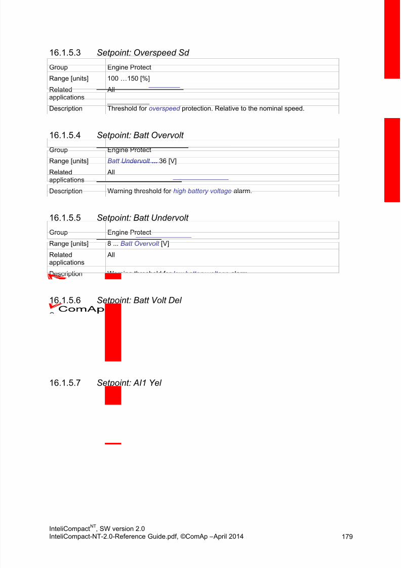
8/15/2019 InteliCompact NT 2.0 Reference Guide
http://slidepdf.com/reader/full/intelicompact-nt-20-reference-guide 179/287
InteliCompactNT
, SW version 2.0InteliCompact-NT-2.0-Reference Guide.pdf, ©ComAp – April 2014 179
Setpoint: Overspeed Sd16.1.5.3
Group Engine Protect
Range [units] 100 … 150 [%]
Related
applications
All
Description Threshold for overspeed protection. Relative to the nominal speed.
Setpoint: Batt Overvolt16.1.5.4
Group Engine Protect
Range [units] Batt Undervolt ... 36 [V]
Relatedapplications
All
Description Warning threshold for high battery voltage alarm.
Setpoint: Batt Undervolt16.1.5.5
Group Engine Protect
Range [units] 8 ... Batt Overvolt [V]
Relatedapplications
All
Description Warning threshold for low battery voltage alarm.
Setpoint: Batt Volt Del16.1.5.6
Group Engine Protect
Range [units] 0 ... 600 [s]
Relatedapplications
All
Description Delay for low battery voltage alarm.
Setpoint: AI1 Yel16.1.5.7
Group Engine Protect
Range [units] Limits and units depend on analog input configuration
Relatedapplications
All
Description Threshold for the yellow alarm configured to the analog input 1.
8/15/2019 InteliCompact NT 2.0 Reference Guide
http://slidepdf.com/reader/full/intelicompact-nt-20-reference-guide 180/287
InteliCompactNT
, SW version 2.0InteliCompact-NT-2.0-Reference Guide.pdf, ©ComAp – April 2014 180
Setpoint: AI1 Red16.1.5.8
Group Engine Protect
Range [units] Limits and units depend on analog input configuration
Related
applications
All
Description Threshold for the red alarm configured to the analog input 1.
Setpoint: AI1 Del16.1.5.9
Group Engine Protect
Range [units] 0 ... 180 [s]
Relatedapplications
All
Description Delay of the alarms configured to the analog input 1.
Setpoint: AI2 Yel16.1.5.10
Group Engine Protect
Range [units] Limits and units depend on analog input configuration
Relatedapplications
All
Description Threshold for the yellow alarm configured to the analog input 2.
Setpoint: AI2 Red16.1.5.11
Group Engine Protect
Range [units] Limits and units depend on analog input configuration
Relatedapplications
All
Description Threshold for the red alarm configured to the analog input 2.
Setpoint: AI2 Del16.1.5.12
Group Engine Protect
Range [units] 0 ... 180 [s]
Relatedapplications
All
Description Delay of the alarms configured to the analog input 2.

8/15/2019 InteliCompact NT 2.0 Reference Guide
http://slidepdf.com/reader/full/intelicompact-nt-20-reference-guide 181/287
InteliCompactNT
, SW version 2.0InteliCompact-NT-2.0-Reference Guide.pdf, ©ComAp – April 2014 181
Setpoint: AI3 Yel16.1.5.13
Group Engine Protect
Range [units] Limits and units depend on analog input configuration
Related
applications
All
Description Threshold for the yellow alarm configured to the analog input 3.
Setpoint: AI3 Red16.1.5.14
Group Engine Protect
Range [units] Limits and units depend on analog input configuration
Relatedapplications
All
Description Threshold for the red alarm configured to the analog input 3.
Setpoint: AI3 Del16.1.5.15
Group Engine Protect
Range [units] 0 ... 180 [s]
Relatedapplications
All
Description Delay of the alarms configured to the analog input 3.
Setpoint: WrnMaintenance16.1.5.16
Group Engine Protect
Range [units] 0 ... 10000 (OFF) [h]
Relatedapplications
All
Description Adjust this setpoint to the requested next maintenance interval. The value willcount down when engine is running and if reaches zero, the alarmMaintenance timer will appear.
This timer is also available in the value group Statistics, but it cannot be
modified there.
In the event that WrnMaintenance
is set to 10000 h the timer is disabled andnot visible on the controller display.

8/15/2019 InteliCompact NT 2.0 Reference Guide
http://slidepdf.com/reader/full/intelicompact-nt-20-reference-guide 182/287
InteliCompactNT
, SW version 2.0InteliCompact-NT-2.0-Reference Guide.pdf, ©ComAp – April 2014 182
16.1.6 Group: Gener Protect
Setpoint: Overload BOC16.1.6.1
Group Gener Protect
Range [units] 100 ... 200 [%]Relatedapplications
All
Description Limit for the generator overload alarm in % of the nominal power. The delayof this alarm is adjustable by the setpoint Overload Del .
Setpoint: Overload Del16.1.6.2
Group Gener Protect
Range [units] 0 ... 600.0 [s]
Relatedapplications
All
Description Delay for the generator overload alarm. The limit for this alarm is adjustableby the setpoint Overload BOC .
Setpoint: Amps IDMT Del16.1.6.3
Group Gener Protect
Range [units] 1 ... 600 [s]
Related
applications
All
Description
IDMT curve shape selection. Amps IDMT Del is Reaction time of IDMT
protection for 200% overcurrent
IDMT is “very inverse” generator over current protection. Reaction time is notconstant but depends on generator over current level according to thefollowing formula:
H INT :
Reaction time is limited to 3600 = 60 minutes. IDMT protection is not activefor Reaction time values longer than 60 minutes.
I gen is maximal value of all measured phases of generator current.
Example Example of Reaction time for different over current levels. Values in column200% are IDMT Curr Del.
Overcurrent
200% =IDMT Curr
Del
≤ 100% 101% 110%
Reaction time 0.2s No action 20s 2s
2s No action 200s 20s
20s No action No action
(time > 3600s)
200s

8/15/2019 InteliCompact NT 2.0 Reference Guide
http://slidepdf.com/reader/full/intelicompact-nt-20-reference-guide 183/287
InteliCompactNT
, SW version 2.0InteliCompact-NT-2.0-Reference Guide.pdf, ©ComAp – April 2014 183
Setpoint: Short Crct BOC16.1.6.4
Group Gener Protect
Range [units] 100 ... 500 [%]
Relatedapplications
All
Description Limit for the generator short circuit alarm. The delay of this alarm isadjustable by the setpoint Short Crct Del .
Setpoint: Short Crct Del16.1.6.5
Group Gener Protect
Range [units] 0 ... 10.00 [s]
Relatedapplications
All
Description Delay for the generator short circuit alarm. The limit for this alarm isadjustable by the setpoint Short Crct BOC .
Setpoint: Amps Unbal BOC16.1.6.6
Group Gener Protect
Range [units] 1 ... 200 [%]
Relatedapplications
All
Description Threshold for generator current unbalance alarm, relative to the nominalcurrent (setpoint Nomin Current ).
Igen
Nomin al Current Short Crct Sd
Amps IDMT Del
Maximal Reaction time
R e a c t i o n t i m e

8/15/2019 InteliCompact NT 2.0 Reference Guide
http://slidepdf.com/reader/full/intelicompact-nt-20-reference-guide 184/287
InteliCompactNT
, SW version 2.0InteliCompact-NT-2.0-Reference Guide.pdf, ©ComAp – April 2014 184
Setpoint: Amps Unbal Del16.1.6.7
Group Gener Protect
Range [units] 0 ... 600.0 [s]
Related
applications
All
Description Delay for generator current unbalance alarm.
Setpoint: EarthFault Sd16.1.6.8
Group Gener Protect
Range [units] 1 ... 10000 [A]
Relatedapplications
All
Description Limit value for Earth Fault Current protection.
Setpoint: EarthFault Del16.1.6.9
Group Gener Protect
Range [units] 0.1 ... 600.0 [s]
Relatedapplications
All
Description Delay for Earth Fault Current protection.
Setpoint: Gen >V Sd16.1.6.10
Group Gener Protect
Range [units] Gen <V BOC … 200 [%]
Relatedapplications
All
Description Threshold for generator overvoltage alarm, relative to the nominal voltage(setpoint Nominal Volts).
Setpoint: Gen <V BOC16.1.6.11
Group Gener Protect
Range [units] 0 ... Gen >V Sd [%]
Relatedapplications
All
Description Threshold for generator undervoltage alarm, relative to the nominal voltage(setpoint Nominal Volts).

8/15/2019 InteliCompact NT 2.0 Reference Guide
http://slidepdf.com/reader/full/intelicompact-nt-20-reference-guide 185/287

8/15/2019 InteliCompact NT 2.0 Reference Guide
http://slidepdf.com/reader/full/intelicompact-nt-20-reference-guide 186/287
InteliCompactNT
, SW version 2.0InteliCompact-NT-2.0-Reference Guide.pdf, ©ComAp – April 2014 186
Setpoint: Gen Freq Del16.1.6.17
Group Gener Protect
Range [units] 0 ... 600.0 [s]
Related
applications
All
Description Delay for generator underfrequency and overfrequency alarm.
Setpoint: BusMeasError16.1.6.18
Group Gener Protect
Range [units] DISABLED, ENABLED [s]
Relatedapplications
MINT
Description If the protection is ENABLED the Bus Measure error is detected in MINT
application when the voltage on controller’s bus terminals is out of limits 20seconds after:
a) GCB (own) was closed in MAN or AUT mode.b) MCB (feedback) was closed in AUT mode.c) Any other GCB in power management group (on CAN bus)
was closed.The alarm is activated after 20s. However, the GCB (own) closing is blockedimmediately for safety reasons.
Setpoint: Reverse Pwr BOC16.1.6.19
Group Gener Protect
Range [units] 1 ... 50 [%]
Relatedapplications
All
Description Threshold for generator reverse power alarm, relative to the Nominal power .
Setpoint: Reverse Pwr Del16.1.6.20
Group Gener Protect
Range [units] 0 ... 600.0 [s]
Relatedapplications
All
Description Delay for generator reverse power alarm.
Setpoint: ExcitationLoss16.1.6.21
Group Gener Protect
Range [units] 0 ... 150 [%]
Relatedapplications
All
Description Loss of excitation is based on measurement of negative kVAr and it is BOC-type protection. Value is calculated from the Nominal Power. For example for
8/15/2019 InteliCompact NT 2.0 Reference Guide
http://slidepdf.com/reader/full/intelicompact-nt-20-reference-guide 187/287
InteliCompactNT
, SW version 2.0InteliCompact-NT-2.0-Reference Guide.pdf, ©ComAp – April 2014 187
200 kW gen-set 50% will represent -100 kVAr. Default value is 30%.
Setpoint: ExctLoss Del16.1.6.22
Group Gener Protect
Range [units] 0 ... 600 [s]Relatedapplications
All
Description Delay for evaluation of Loss of excitation. Default value is 2 s.
16.1.7 Group: Pwr Management
Setpoint: Pwr Management16.1.7.1
Group Pwr ManagementRange [units] DISABLED, ENABLED [-]
Relatedapplications
MINT
Description The setpoint enables and disables the gen-set to be active within the powermanagement of the group. It performs automatic load dependent starts andstops or load demand swap. If the power management is disabled the gen-set’s nominal power is not part of the power management calculation,however gen-set itself will start/stop onSys Start/Stop signal.
Setpoint: Pwr Manag Del16.1.7.2Group Power Management
Range [units] 0 … 3600 [s]
Relatedapplications
MINT
Description Setpoint defines delay of the Power management. When Sys Start/Stopsignal is activated and the gen-sets should start, all the engines (wherePower Management is enabled) are started and stay running for time periodspecified by this parameter. After this period elapses, only the gen-set(s)needed according to the Power Management calculation (i.e. SystReserveOK = 1) stay running and the rest is stopped.
Pwr management Del is useful, when you need to start gen-sets to anunknown load. Setting for example 360s (6minutes) and activating SysStart/Stop will force all gen-sets to start and run for 6 minutes despite of thepower management setting.
By setting “0” the Power Management function is enabled immediately.
Setpoint: #PowerMgmtMode16.1.7.3
Group Power Management
Range [units] ABS(kW), REL(%) ... [-]Related MINT

8/15/2019 InteliCompact NT 2.0 Reference Guide
http://slidepdf.com/reader/full/intelicompact-nt-20-reference-guide 188/287
InteliCompactNT
, SW version 2.0InteliCompact-NT-2.0-Reference Guide.pdf, ©ComAp – April 2014 188
applications
Description Use this setpoint to select whether the power management has to be basedon absolute reserve (in kW) or relative (in %).

8/15/2019 InteliCompact NT 2.0 Reference Guide
http://slidepdf.com/reader/full/intelicompact-nt-20-reference-guide 189/287
InteliCompactNT
, SW version 2.0InteliCompact-NT-2.0-Reference Guide.pdf, ©ComAp – April 2014 189
Setpoint: Priority16.1.7.4
Group Pwr Management
Range [units] 1 ... 32 [-]
Related
applications
MINT
Description This setpoint adjusts the priority of the gen-set within the group. A lowernumber represents a “higher ” priority, i.e. a gen-set with lower number willstart before another one with higher number.
If the binary input Top Priority is active, the gen-set gets the highestpriority (0) independent of the setpoint setting.
NOTE: If more than one gen-set have the same priority they will act as “one big” gen-set.
CAUTION:
Value of the setpoint Priority is taken into account only for Load DemandStart/Stop power management.
Setpoint: #PriorAutoSwap16.1.7.5
Group Pwr management
Range [units] DISABLED, RUN HOURS, EFFICENT
Relatedapplications
MINT
Description This setpoint selects the method of optimization of priorities:
DISABLED Optimization is disabled. Priorities are given directly by thevalues adjusted in the setpoint Priority .
RUN HOURS The priority setpoints are automatically updated (swapped)to equalize running hours of the gen-sets or to keepconstant difference of running hours by the controller.
EFFICENT This method changes the priorities (not the setpoints itself)to optimize which gen-sets are running according to their
capacities and actual load demand. Note that this priorityswapping function may be used only if #Pwr mgmt mode is set to ABS (kW).
Optimal power band (number of running gen-sets) iscalculated based on the nominal power of each gen-set,their Run Hours and requested Load reserve. For gen-setswith the same nominal power also run hour equalization isbeing performed.
NOTE:
Binary input Top Priority can be used only if #PriorAutoSwap = DISABLED

8/15/2019 InteliCompact NT 2.0 Reference Guide
http://slidepdf.com/reader/full/intelicompact-nt-20-reference-guide 190/287
InteliCompactNT
, SW version 2.0InteliCompact-NT-2.0-Reference Guide.pdf, ©ComAp – April 2014 190
NOTE:
Since version IC-NT 2.0 setting #RunHrsMaxDiff = 0 or 65000 no longer switchoff the function of run hours equalization.
NOTE: There is additional 200 ms time gap after SysAMFstrtDel in order to allow thecontrollers to calculate which gen-set has to start.
Setpoint: #SysAMFStrtDel16.1.7.6
Group Power Management
Range [units] 0 ... 600 [s]
Relatedapplications
MINT
Description This setpoint adjusts the delay of the system activation after the binary inputSys Start/Stop has been activated.
This delay is typically used as “ AMF start delay”, similar to the setpointEmergStart Del in SPtM, on multiple AMF applications withoutMainsCompact. See MINT basic schemes.
Setpoint: #SysAMFStopDel16.1.7.7
Group Power Management
Range [units] 0 ... 600 [s]
Relatedapplications
MINT
Description This setpoint adjusts the delay of the system deactivation after the binaryinput Sys Start/Stop has been deactivated.
This delay is typically used as “Mains return delay”, similar to the setpointMainsReturnDel in SPtM, on multiple AMF applications withoutMainsCompact. See MINT basic schemes.
Setpoint: #LoadResStrt 116.1.7.8
Group Power Management
Range [units] -32000 ... LoadResStop 1 [#PowerMgmtMode dependent]
Relatedapplications
MINT
Description This setpoint adjusts the reserve for start if the set 1 of reserves is selected,i.e. binary input Load Reserve 2 is not active. See the power managementdescription to learn more about reserves.

8/15/2019 InteliCompact NT 2.0 Reference Guide
http://slidepdf.com/reader/full/intelicompact-nt-20-reference-guide 191/287
InteliCompactNT
, SW version 2.0InteliCompact-NT-2.0-Reference Guide.pdf, ©ComAp – April 2014 191
Setpoint: #LoadResStop 116.1.7.9
Group Power Management
Range [units] LoadResStrt 1 ... 32000 [#PowerMgmtMode dependent]
Related
applications
MINT
Description This setpoint adjusts the reserve for stop if the set 1 of reserves is selected,i.e. binary input Load Reserve 2 is not active. See the power managementdescription to learn more about reserves.
Setpoint: #LoadResStrt 216.1.7.10
Group Power Management
Range [units] -32000 ... LoadResStop 2 [#PowerMgmtMode dependent]
Relatedapplications
MINT
Description This setpoint adjusts the reserve for start if the set 2 of reserves is selected,i.e. binary input Load Reserve 2 is active. See the power managementdescription to learn more about reserves.
Setpoint: #LoadResStop 216.1.7.11
Group Power Management
Range [units] LoadResStrt 2 ... 32000 [#PowerMgmtMode dependent]
Relatedapplications
MINT
Description This setpoint adjusts the reserve for stop if the set 2 of reserves is selected,i.e. binary input Load Reserve 2 is active. See the power managementdescription to learn more about reserves.
Setpoint: #MinRun Power16.1.7.12
Group Power Management
Range [units] 0 ... 65000 [kW]
Relatedapplications
MINT
Description In case of activation LBI MinRunPower -> based on the nominal power, thegen-sets needed for equalizing the actual MinRunPower requirement arestarted (or kept running even if stop reserve is fulfilled). Note, that LBI’s MinRun Power needs to be activated on all gen-sets in the same time.
Setpoint: #NextStrt Del16.1.7.13
Group Power Management
Range [units] 0 ... 3600 [s]
Relatedapplications
MINT
Description This setpoint adjusts the delay for starting the next gen-set after the reservehas dropped below the reserve for start.

8/15/2019 InteliCompact NT 2.0 Reference Guide
http://slidepdf.com/reader/full/intelicompact-nt-20-reference-guide 192/287
InteliCompactNT
, SW version 2.0InteliCompact-NT-2.0-Reference Guide.pdf, ©ComAp – April 2014 192
Setpoint: #OverldNextDel16.1.7.14
Group Power Management
Range [units] 0 ... 3600 [s]
Related
applications
MINT
Description This setpoint adjusts the delay for starting the next gen-set after the reservehas dropped below zero, i.e. the system is overloaded.
NOTE: Adjust this setpoint as short as possible to avoid system shutdown due tooverload caused by too fast load rising.
Setpoint: #NextStopDel16.1.7.15
Group Power Management
Range [units] 0 ... 3600 [s]Relatedapplications
MINT
Description This setpoint adjusts the delay for stopping the gen-set after the reserve hasrisen above the reserve for stop.
Setpoint: #SlowStopDel16.1.7.16
Group Power Management
Range [units] 0 ... 600 [s]
Relatedapplications
MINT
Description If a slow stop red alarm occurs, the affected gen-set will notify the other gen-sets that it is no longer available, but will remain loaded until the next gen-setstarts and connects to the bus. This setpoint adjusts the maximum time theaffected gen-set will wait for another one to start. After this period it willperform a slow stop regardless of other gen-sets.
Setpoint: RunHoursBase16.1.7.17
Group Power Management
Range [units] 0 ... 200000 [h]
Relatedapplications
MINT
Description Running hours base corrects actual Running hours differences betweenparticular gen-sets.
Example:Gen-set 1 actual Running hours = 1000 h.Gen-set 2 actual Running hours = 2000 h.
Adjust RunHourBase for Gen-set 1 = 1000 h and RunHourBase
forGen-set 2 = 2000 h to be on the same base for Running Hours Equalization.

8/15/2019 InteliCompact NT 2.0 Reference Guide
http://slidepdf.com/reader/full/intelicompact-nt-20-reference-guide 193/287
InteliCompactNT
, SW version 2.0InteliCompact-NT-2.0-Reference Guide.pdf, ©ComAp – April 2014 193
Setpoint: #RunHrsMaxDiff16.1.7.18
Group Power Management
Range [units] 0 … 65000 [h]
Related
applications
MINT
Description Maximum allowed Running hours difference between gen-sets.
Running Hours Equalization function is only active when:
PwrManagement = ENABLED
BI Sys Start/Stop = ACTIVE
#PriorAutoSwap = RUN HOURS
#RunHrsMaxDiff is not set to 0 or 65000; only for fw version less than2.0 (these values DISABLE Running Hours Equalization function)
When running gen-set reaches #RunHrsMaxDiff value, its Priority is
automatically swapped with the lowest priority gen-set that takes part inRunning Hours Equalization.
CAUTION:To disable “Running Hours Equalization” function (setpoint #RunHrsMaxDiff ):
setpoint #RunHrsMaxDiff = 65000 => for version IC-NT 1.3 and 1.3.1setpoint #RunHrsMaxDiff 0 => for version IC-NT 1.4setpoint #RunHrsMaxDiff 0 or 65000 => for version IC-NT 1.4.1+setpoint #PriorAutoSwap ≠ RUN HOURS => for version IC-NT 2.0+
Setpoint: #PwrBnChngDIUp16.1.7.19
Group Pwr Management
Range [units] 0 - 3600 [s]
Relatedapplications
MINT
Description Power Band Change Delay Up - this setpoint is used for adjusting the delay ofchanging the power band if the load demand rose above the upper limit of thecurrent power band. Setpoint is taken into account only if #PriorAutoSwap =EFFICENT.
Setpoint: #PwrBnChngDIDn16.1.7.20
Group Pwr Management
Range [units] 0 - 3600 [s]
Relatedapplications
MINT
Description Power Band Change Delay Down - this setpoint is used for adjusting the delay ofchanging the power band if the load demand drops below the lower limit of thecurrent power band. Setpoint is taken into account only if #PriorAutoSwap =EFFICENT.

8/15/2019 InteliCompact NT 2.0 Reference Guide
http://slidepdf.com/reader/full/intelicompact-nt-20-reference-guide 194/287
InteliCompactNT
, SW version 2.0InteliCompact-NT-2.0-Reference Guide.pdf, ©ComAp – April 2014 194
16.1.8 Group: AMF Settings
Setpoint: EmergStart Del16.1.8.1
Group AMF Settings
Range [units] 0 ... 600 [s]Relatedapplications
SPtM
Description Delay between the mains failure and the automatic start of the gen-set to an AMF operation. See more in the AMF operation chapter.
Setpoint: MainsReturnDel16.1.8.2
Group AMF Settings
Range [units] 1 … 3600 [s]
Relatedapplications
SPtM
Description This is a “mains stabilization” time. If the mains are continuously healthy forthis period after they have returned, the controller will finish the AMFoperation (e.g. by reverse synchronization or a switchover). See more in the AMF operation chapter.
Setpoint: Mains >V16.1.8.3
Group AMF Settings
Range [units] Mains <V ... 150 [%]
Relatedapplications
SPtM
Description Threshold for detection of mains failure due to overvoltage. The setpoint isadjusted relative to the generator nominal voltage (setpoint Nominal Volts).
Setpoint: Mains <V16.1.8.4
Group AMF Settings
Range [units] 50 ... Mains >V [%]
Relatedapplications
SPtM
Description Threshold for detection of mains failure due to undervoltage. The setpoint isadjusted relative to the generator nominal voltage (setpoint Nominal Volts).
Setpoint: Mains V Del16.1.8.5
Group AMF Settings
Range [units] 0 ... 600.0 [s]
Relatedapplications
SPtM
Description Delay for detection of mains failure due to over/undervoltage.

8/15/2019 InteliCompact NT 2.0 Reference Guide
http://slidepdf.com/reader/full/intelicompact-nt-20-reference-guide 195/287
InteliCompactNT
, SW version 2.0InteliCompact-NT-2.0-Reference Guide.pdf, ©ComAp – April 2014 195
Setpoint: Mains >Freq16.1.8.6
Group AMF Settings
Range [units] Mains <Freq ... 150 [%]
Related
applications
SPtM
Description Threshold for detection of mains failure due to overfrequency. The setpoint isadjusted relative to the generator nominal frequency (setpoint Nominal Freq).
Setpoint: Mains <Freq16.1.8.7
Group AMF Settings
Range [units] 50 ... Mains >Freq [%]
Relatedapplications
SPtM
Description Threshold for detection of mains failure due to underfrequency. The setpointis adjusted relative to the generator nominal frequency (setpoint NominalFreq).
Setpoint: Mains Freq Del16.1.8.8
Group AMF Settings
Range [units] 0 ... 600.0 [s]
Relatedapplications
SPtM
Description Delay for detection of mains failure due to over/underfrequency.
Setpoint: VectorShiftLim16.1.8.9
Group AMF Settings
Range [units] 1 ... 45 [°]
Relatedapplications
SPtM
Description Threshold for detection of mains failure due to Vector shift. A mains failure isdetected immediately when the vector surge has occurred without any delay.
Setpoint: Transfer Del16.1.8.10
Group AMF Settings
Range [units] 0 ... 600 [s]
Relatedapplications
SPtM
Description When a switchover of the MCB and GCB is performed (in both directions),this setpoint defines the period between one breaker being opened and theother closed.

8/15/2019 InteliCompact NT 2.0 Reference Guide
http://slidepdf.com/reader/full/intelicompact-nt-20-reference-guide 196/287
InteliCompactNT
, SW version 2.0InteliCompact-NT-2.0-Reference Guide.pdf, ©ComAp – April 2014 196
Setpoint: MCB Close Del16.1.8.11
Group AMF Settings
Range [units] 0 ... 60 [s]
Related
applications
SPtM
Description If the gen-set is still not in AMF operation e.g. GCB has not started and notclosed yet, and the mains becomes healthy again, the MCB is reclosed afterthe mains are continuously healthy for this time period.
NOTE: If the gen-set is already supplying the load, the setpoint MainsReturnDel willbe active instead of this setpoint.
Setpoint: MCB Opens On16.1.8.12
Group AMF Settings
Range [units] MAINSFAIL, GENRUN [-]
Relatedapplications
SPtM
Description Adjusting of the condition when MCB opens after Mains fail:
MAINSFAIL: Controller opens the MCB when Mains fail is detected (24V DCcontrolled circuit breaker or contactor expected).
GENRUN: Controller opens the MCB only after the gen-set has been started,i.e. the generator voltage is present to open the MCB (230V AC controlledbreaker expected).
Setpoint: RetFromIsland16.1.8.13
Group AMF Settings
Range [units] MANUAL, AUTO [-]
Relatedapplications
SPtM
Description MANUAL: When RetFromIsland = MANUAL and there is a Mains Fail, gen-sets are started and after Mains Return operator can manually transfer theload back to Mains even if the controller stays in AUT mode.
AUTO: No automatic mode change is performed.
NOTE: Select RetFromIsland = MANUAL in case you need to manually control themoment when the load is transferred back to the mains.

8/15/2019 InteliCompact NT 2.0 Reference Guide
http://slidepdf.com/reader/full/intelicompact-nt-20-reference-guide 197/287
InteliCompactNT
, SW version 2.0InteliCompact-NT-2.0-Reference Guide.pdf, ©ComAp – April 2014 197
Setpoint: BreakerOverlap16.1.8.14
Group AMF Settings
Range [units] 0,0 ... 300,0 [s]
Related
applications
SPtM
Description This setpoint adjusts maximal time period the both GCB and MCB are closedtogether during the interrupt-free transfer of the load from the mains to thegen-set and vice versa.
Setpoint: ReturnFromTEST16.1.8.15
Group AMF Settings
Range [units] DISABLED, ENABLED [-]
Relatedapplications
SPtM
Description Adjusting of the behaviour of the controller if the gen-set is supplying the loadin TEST mode (after mains have failed) and the mains are recovered:
DISABLED: The gen-set will remain running and supplying the load untiloperating mode is changed. See Manual return from test description.
ENABLED: The controller will transfer the load back to the healthy mains andremain running unloaded. See Automatic return from test description.
Setpoint: MCB Logic16.1.8.16
Group AMF Settings
Range [units] CLOSE-ON, CLOSE-OFF [-]
Relatedapplications
SPtM
Description The setpoint selects behaviour of the MCB Close/Open output:
CLOSE-ON: Binary output MCB close/open is activated, when the MCB isrequested to be closed (normal, positive logic).
CLOSE-OFF: Binary output MCB close/open is activated, when the MCB isrequested to be open (inverted, negative logic).
CAUTION! For safety reasons it is recommended to use negative logic (CLOSE-OFF).Using positive logic could cause the mains to be disconnected accidentallywhen the controller is switched off or a wire is broken.

8/15/2019 InteliCompact NT 2.0 Reference Guide
http://slidepdf.com/reader/full/intelicompact-nt-20-reference-guide 198/287
InteliCompactNT
, SW version 2.0InteliCompact-NT-2.0-Reference Guide.pdf, ©ComAp – April 2014 198
16.1.9 Group: Sync/Load Ctrl
Setpoint: Speed Gov Char16.1.9.1
Group Sync/Load Ctrl
Range [units] POSITIVE, NEGATIVE [-]Relatedapplications
All
Description This setpoint selects the characteristic of the speed governor output of thecontroller. Adjust it according to the behaviour of the remote speed input ofthe governor:
POSITIVE: raising the voltage on the governor remote speed input causesengine speed to rise.
NEGATIVE: raising the voltage on the governor remote speed input causesengine speed to go down.
Setpoint: Speed Gov Bias16.1.9.2
Group Sync/Load Ctrl
Range [units] SpeedGovLowLim ... SpeedGovHiLim [V]
Relatedapplications
All
Description This setpoint adjusts the initial voltage level for the speed governor output,which is present on the output, if no speed or power regulation loop is active.
See the chapter Governor interface for details about the recommendedsettings for various governor types. To make a fine adjustment, start the gen-
set in MAN mode, leave it running unloaded and then make fine adjustmentof this setpoint to achieve nominal engine speed.
Setpoint: SpeedGovLowLim16.1.9.3
Group Sync/Load Ctrl
Range [units] 0 … SpeedGovHiLim [V]
Relatedapplications
All
Description Lower limit of the speed governor output. Use this setpoint to adjust the
governor output range according to your governor type.
Setpoint: SpeedGovHiLim16.1.9.4
Group Sync/Load Ctrl
Range [units] SpeedGovLowLim … 10.00 [V]
Relatedapplications
All
Description Upper limit of the speed governor output. Use this setpoint to adjust thegovernor output range according to your governor type.
8/15/2019 InteliCompact NT 2.0 Reference Guide
http://slidepdf.com/reader/full/intelicompact-nt-20-reference-guide 199/287
InteliCompactNT
, SW version 2.0InteliCompact-NT-2.0-Reference Guide.pdf, ©ComAp – April 2014 199
Setpoint: TauSpeedActuat16.1.9.5
Group Sync/Load Ctrl
Range [units] 1 ... 300 [s]
Related
applications
All
Description Time constant of the speed actuator connected to the binary outputs SpeedUp/Speed Down. Setting of this parameter affects the length of the pulses onthese binary outputs. This is to match the reaction of the controller’s regulatorwith the actual reaction time of the actuator.
Setpoint: Voltage Window16.1.9.6
Group Sync/Load Ctrl
Range [units] 0 … 100.0 [%]
Relatedapplications
All
Description This setpoint adjusts maximum difference between generator and mains/busvoltage in respective phases for synchronizing.
Setpoint: Phase Window16.1.9.7
Group Sync/Load Ctrl
Range [units] 0 ... 90 [°]
Relatedapplications
All
Description This setpoint adjusts the maximum absolute value of difference betweenactual phase angle between the generator and mains/bus voltages forsynchronizing.
NOTE: To disable issuing the breaker close command (i.e. for test purpose) adjustthis setpoint to 0. Synchronizing will continue until a timeout occurs or thebreaker is closed externally.
0
X
X = PhaseWindow
-X
Allowed range of
phase angle
difference

8/15/2019 InteliCompact NT 2.0 Reference Guide
http://slidepdf.com/reader/full/intelicompact-nt-20-reference-guide 200/287
InteliCompactNT
, SW version 2.0InteliCompact-NT-2.0-Reference Guide.pdf, ©ComAp – April 2014 200
Setpoint: Dwell Time16.1.9.8
Group Sync/Load Ctrl
Range [units] 0 … 25.0 [s]
Related
applications
All
Description The period of time that the phase angle difference must be within +/- PhaseWindow and voltage difference within Voltage Window before the breaker isclosed.
Setpoint: Freq Gain16.1.9.9
Group Sync/Load Ctrl
Range [units] 0 ... 200.0 [%]
Relatedapplications
All
Description Gain of the frequency control PI loop.
Setpoint: Freq Int16.1.9.10
Group Sync/Load Ctrl
Range [units] 0 ... 100 [%]
Relatedapplications
All
Description Relative integration factor of the frequency control loop.
Setpoint: Angle Gain16.1.9.11
Group Sync/Load Ctrl
Range [units] 0 ... 200.0 [%]
Relatedapplications
All
Description Gain of the phase angle control loop.
During synchronization, first the frequency loop is started to match thegenerator frequency with the mains or bus and after that the phase angle
loop is started to match the phase angle.

8/15/2019 InteliCompact NT 2.0 Reference Guide
http://slidepdf.com/reader/full/intelicompact-nt-20-reference-guide 201/287
InteliCompactNT
, SW version 2.0InteliCompact-NT-2.0-Reference Guide.pdf, ©ComAp – April 2014 201
Setpoint: Load Ramp16.1.9.13
Group Sync/Load Cont
Range [units] 0 ... GCB Open Del [s]
Related
applications
All
Description All changes of requested gen-set load (except in load-sharing mode) are notmade as one step, but are ramped – i.e. the requested load is changingslowly with the rate adjusted by this setpoint.
The rate is adjusted in seconds for 100% load change (from 0 to 100% ofnominal power). So if the requested load change is 50% of nominal power,the ramp duration will be 50% of this setpoint.
The ramp takes place in the following situations:
The gen-set has been just synchronized and is ramping up to thetarget load level (e.g. baseload in parallel to mains operation oraverage gen-set load in multiple load-sharing operation)
The gen-set is running parallel to the mains and baseload ischanged.
The gen-set is being unloaded before opening the GCB and stop. Inthis case the end load level is adjusted by the setpoint GCB OpenLevel and the timeout for unloading is adjusted by the setpoint GCBOpen Del .
Setpoint: Load Gain16.1.9.14
Group Sync/Load Ctrl
Range [units] 0 ... 200.0 [%]
Relatedapplications
All
Description Gain of the load control PI loop.
Setpoint: Load Int16.1.9.15
Group Sync/Load Ctrl
Range [units] 0 ... 100 [%]
Relatedapplications
All
Description Relative integration factor of the load control loop.
Setpoint: GCB Open Level16.1.9.16
Group Sync/Load Ctrl
Range [units] 0 ... 100 [%]
Relatedapplications
All
Description After a stop command has been issued in parallel to mains or other gen-setsoperation, the gen-set load is ramped down before the GCB will open. Usethis setpoint to adjust the end-point of the ramp, e.g. the load level (in % ofNominal Power ) where the GCB will be opened.
8/15/2019 InteliCompact NT 2.0 Reference Guide
http://slidepdf.com/reader/full/intelicompact-nt-20-reference-guide 202/287
InteliCompactNT
, SW version 2.0InteliCompact-NT-2.0-Reference Guide.pdf, ©ComAp – April 2014 202
Setpoint: GCB Open Del16.1.9.17
Group Sync/Load Ctrl
Range [units] Load Ramp ... 1800 [s]
Related
applications
All
Description Use this setpoint to adjust the timeout for reaching the load level GCB OpenLevel during the gen-set is being unloaded. When the timeout has elapsed,the GCB will open regardless of the load.
Setpoint: Sync Timeout16.1.9.18
Group Sync/Load Ctrl
Range [units] 1 ... 1800 [s]
Relatedapplications
All
Description This setpoint adjusts the maximum duration of synchronizing. If synchronizingis not successful within this period of time, the Sync Timeout orRevSyncTimeout alarm will be issued.
Setpoint: LoadShare Gain16.1.9.19
Group Sync/Load Ctrl
Range [units] 0 ... 200.0 [%]
Relatedapplications
MINT
Description Gain of the load sharing control PI loop.
Setpoint: LoadShare Int16.1.9.20
Group Sync/Load Ctrl
Range [units] 0 ... 100 [%]
Relatedapplications
MINT
Description Relative integration factor of load sharing control loop.

8/15/2019 InteliCompact NT 2.0 Reference Guide
http://slidepdf.com/reader/full/intelicompact-nt-20-reference-guide 203/287
InteliCompactNT
, SW version 2.0InteliCompact-NT-2.0-Reference Guide.pdf, ©ComAp – April 2014 203
16.1.10 Group: Volt/PF Ctrl
Setpoint: AVRi Bias16.1.10.1
Group Volt/PF Ctrl
Range [units] 0 ... 100.0 [%]Relatedapplications
All
Description This setpoint adjusts the initial PWM level for the AVR output, which ispresent on the output, if no voltage or power factor regulation loop is active.
See the chapter AVR interface for details about the recommended settingsfor various AVR types.
NOTE: The voltage level on the AVR remote voltage input depends also on AVRioutput wiring and potentiometer position.
Setpoint: Voltage Gain16.1.10.2
Group Volt/PF Ctrl
Range [units] 0 … 200.0 [%]
Relatedapplications
All
Description Gain of the voltage control PI loop.
Setpoint: Voltage Int16.1.10.3
Group Volt/PF Ctrl
Range [units] 0 ... 100 [%]
Relatedapplications
All
Description Relative integration factor of the voltage control loop.
Setpoint: PF Gain16.1.10.4
Group Volt/PF Ctrl
Range [units] 0 ... 200.0 [%]
Relatedapplications
All
Description Gain of power factor control PI loop.

8/15/2019 InteliCompact NT 2.0 Reference Guide
http://slidepdf.com/reader/full/intelicompact-nt-20-reference-guide 204/287
InteliCompactNT
, SW version 2.0InteliCompact-NT-2.0-Reference Guide.pdf, ©ComAp – April 2014 204
Setpoint: PF Int16.1.10.5
Group Volt/PF Ctrl
Range [units] 0 ... 100 [%]
Related
applications
All
Description Relative integration factor of the power factor control loop.
Setpoint: VAr Share Gain16.1.10.6
Group Volt/PF Ctrl
Range [units] 0 ... 200.0 [%]
Relatedapplications
MINT
Description Gain of VAr sharing control PI loop.
Setpoint: VAr Share Int16.1.10.7
Group Volt/PF Ctrl
Range [units] 0 ... 100 [%]
Relatedapplications
MINT
Description Relative integration factor of VAr sharing control loop.
16.1.11 Group: ExtI/O Protect
Setpoint: IOM AI1 Yel16.1.11.1
Group ExtI/O Protect
Range [units] Limits and units depend on analog input configuration
Relatedapplications
All
Description Threshold for the yellow alarm configured to the analog input 1 of theextension module IG-IOM or IGS-PTM.
Setpoint: IOM AI1 Red16.1.11.2
Group ExtI/O Protect
Range [units] Limits and units depend on analog input configuration
Relatedapplications
All
Description Threshold for the red alarm configured to the analog input 1 of the extensionmodule IG-IOM or IGS-PTM.

8/15/2019 InteliCompact NT 2.0 Reference Guide
http://slidepdf.com/reader/full/intelicompact-nt-20-reference-guide 205/287
InteliCompactNT
, SW version 2.0InteliCompact-NT-2.0-Reference Guide.pdf, ©ComAp – April 2014 205
Setpoint: IOM AI1 Del16.1.11.3
Group ExtI/O Protect
Range [units] 0 ... 180 [s]
Related
applications
All
Description Delay of the alarms configured to the analog input 1 of the extension module IG-IOM or IGS-PTM.
Setpoint: IOM AI2 Yel16.1.11.4
Group ExtI/O Protect
Range [units] Limits and units depend on analog input configuration
Relatedapplications
All
Description Threshold for the yellow alarm configured to the analog input 2 of theextension module IG-IOM or IGS-PTM.
Setpoint: IOM AI2 Red16.1.11.5
Group ExtI/O Protect
Range [units] Limits and units depend on analog input configuration
Relatedapplications
All
Description Threshold for the red alarm configured to the analog input 2 of the extension
module IG-IOM or IGS-PTM.
Setpoint: IOM AI2 Del16.1.11.6
Group ExtI/O Protect
Range [units] 0 ... 180 [s]
Relatedapplications
All
Description Delay of the alarms configured to the analog input 2 of the extension module IG-IOM or IGS-PTM.
Setpoint: IOM AI3 Yel16.1.11.7
Group ExtI/O Protect
Range [units] Limits and units depend on analog input configuration
Relatedapplications
All
Description Threshold for the yellow alarm configured to the analog input 3 of theextension module IG-IOM or IGS-PTM.

8/15/2019 InteliCompact NT 2.0 Reference Guide
http://slidepdf.com/reader/full/intelicompact-nt-20-reference-guide 206/287
InteliCompactNT
, SW version 2.0InteliCompact-NT-2.0-Reference Guide.pdf, ©ComAp – April 2014 206
Setpoint: IOM AI3 Red16.1.11.8
Group ExtI/O Protect
Range [units] Limits and units depend on analog input configuration
Related
applications
All
Description Threshold for the red alarm configured to the analog input 3 of the extensionmodule IG-IOM or IGS-PTM.
Setpoint: IOM AI3 Del16.1.11.9
Group ExtI/O Protect
Range [units] 0 … 180 [s]
Relatedapplications
All
Description Delay of the alarms configured to the analog input 3 of the extension module IG-IOM or IGS-PTM.
Setpoint: IOM AI4 Yel16.1.11.10
Group ExtI/O Protect
Range [units] Limits and units depend on analog input configuration
Relatedapplications
All
Description Threshold for the yellow alarm configured to the analog input 4 of the
extension module IG-IOM or IGS-PTM.
Setpoint: IOM AI4 Red16.1.11.11
Group ExtI/O Protect
Range [units] Limits and units depend on analog input configuration
Relatedapplications
All
Description Threshold for the red alarm configured to the analog input 4 of the extensionmodule IG-IOM or IGS-PTM.
Setpoint: IOM AI4 Del16.1.11.12
Group ExtI/O Protect
Range [units] 0 ... 180 [s]
Relatedapplications
All
Description Delay of the alarms configured to the analog input 4 of the extension module IG-IOM or IGS-PTM.

8/15/2019 InteliCompact NT 2.0 Reference Guide
http://slidepdf.com/reader/full/intelicompact-nt-20-reference-guide 207/287
InteliCompactNT
, SW version 2.0InteliCompact-NT-2.0-Reference Guide.pdf, ©ComAp – April 2014 207
16.1.12 Group: SMS/E-Mail
Setpoint: Yel Alarm Msg16.1.12.1
Group SMS/E-Mail
Range [units] OFF, ON [-]Relatedapplications
All
Description Set this setpoint to YES if you want to get messages when a yellow alarmoccurs.
NOTE: The target address (GSM phone number or e-mail address) must be setcorrectly to the setpoint(s) Phone/Addr 1 or Phone/Addr 2 .
Setpoint: Red Alarm Msg16.1.12.2
Group SMS/E-Mail
Range [units] OFF, ON [-]
Relatedapplications
All
Description Set this setpoint to YES if you want to get messages when a red alarm
occurs.
NOTE: The target address (GSM phone number or e-mail address) must be setcorrectly to the setpoint(s) Phone/Addr 1 or Phone/Addr 2 .
Setpoint: Event Msg16.1.12.3
Group SMS/E-Mail
Range [units] OFF, ON [-]
Relatedapplications
All
Description Set this setpoint to ON if you want to get messages when a new eventoccurs. For target address (GSM phone number or e-mail address) must beset correctly to the setpoint(s) TelNo/Addr Ch1 or TelNo/Addr Ch2 .

8/15/2019 InteliCompact NT 2.0 Reference Guide
http://slidepdf.com/reader/full/intelicompact-nt-20-reference-guide 208/287
InteliCompactNT
, SW version 2.0InteliCompact-NT-2.0-Reference Guide.pdf, ©ComAp – April 2014 208
Setpoint: TelNo/Addr Ch116.1.12.4
Setpoint: TelNo/Addr Ch216.1.12.5
16.1.13 Group: AnalogSwitches
Setpoint: AnaSwitch1 ON16.1.13.1
Group AnalogSwitches
Range [units] Limits and units depend on analog input configurationRelatedapplications
All
Description Threshold level for switching ON the analog switch assigned to the analoginput 1 of the controller.
Group SMS/E-Mail
Range [units] [-]
Relatedapplications
All
Description Enter in this setpoint either a valid GSM phone number or e-mail addresswhere the alarm messages shall be sent.
NOTE: For GSM numbers use either the national format (i.e. the number you woulddial if you wanted to make a local call) or the full international formatbeginning with a “+” character followed by the country prefix.
NOTE: This setpoint can be modified from a PC only!
Group SMS/E-Mail
Range [units] [-]
Relatedapplications
All
Description Enter in this setpoint either a valid GSM phone number or e-mail where thealarm messages shall be sent.
NOTE: For GSM numbers use either the national format (i.e. the number you woulddial if you wanted to make a local call) or the full international formatbeginning with a “+” character followed by the country prefix.
NOTE: This setpoint can be modified from a PC only!
8/15/2019 InteliCompact NT 2.0 Reference Guide
http://slidepdf.com/reader/full/intelicompact-nt-20-reference-guide 209/287
InteliCompactNT
, SW version 2.0InteliCompact-NT-2.0-Reference Guide.pdf, ©ComAp – April 2014 209
Setpoint: AnaSwitch1 OFF16.1.13.2
Group AnalogSwitches
Range [units] Limits and units depend on analog input configuration
Related
applications
All
Description Threshold level for switching OFF the analog switch assigned to the analoginput 1 of the controller.
Setpoint: AnaSwitch2 ON16.1.13.3
Group AnalogSwitches
Range [units] Limits and units depend on analog input configuration
Relatedapplications
All
Description Threshold level for switching ON the analog switch assigned to the analoginput 2 of the controller.
Setpoint: AnaSwitch2 OFF16.1.13.4
Group AnalogSwitches
Range [units] Limits and units depend on analog input configuration
Relatedapplications
All
Description Threshold level for switching OFF the analog switch assigned to the analog
input 2 of the controller.
Setpoint: AnaSwitch3 ON16.1.13.5
Group AnalogSwitches
Range [units] Limits and units depend on analog input configuration
Relatedapplications
All
Description Threshold level for switching ON the analog switch assigned to the analoginput 3 of the controller.
Setpoint: AnaSwitch3 OFF16.1.13.6
Group AnalogSwitches
Range [units] Limits and units depend on analog input configuration
Relatedapplications
All
Description Threshold level for switching OFF the analog switch assigned to the analoginput 3 of the controller.

8/15/2019 InteliCompact NT 2.0 Reference Guide
http://slidepdf.com/reader/full/intelicompact-nt-20-reference-guide 210/287
InteliCompactNT
, SW version 2.0InteliCompact-NT-2.0-Reference Guide.pdf, ©ComAp – April 2014 210
Setpoint: PowerSwitch ON16.1.13.7
Group AnalogSwitches
Range [units] 0 … 32000 [kW]
Related
applications
All
Description On level for power switch activation, see Power switch chapter.
Setpoint: PowerSwitchOFF16.1.13.8
Group AnalogSwitches
Range [units] 0 ... 32000 [kW]
Relatedapplications
All
Description Off level for power switch activation, see Power switch chapter.
16.1.14 Group: Date/Time
Setpoint: Time Stamp Per16.1.14.1
Group Date/Time
Range [units] 0 … 240 [min]
Relatedapplications
All
Description If the gen-set is running, the Time stamp records are written periodically intothe history. Use this setpoint to adjust the period in which these records arewritten. Adjust the setpoint to 0 to disable this function.
NOTE: The shorter the timestamp period, the earlier the history log will beoverwritten by Time stamp records. For example, if the period is set to 1 min,
the history will be overwritten after approx. 2 hours of continuous operation.
Setpoint: #SummerTimeMod16.1.14.2
Group Date/Time
Range [units] DISABLED, WINTER, SUMMER, WINTER-S, SUMMER-S [-]
Relatedapplications
All
Description DISABLED: time mode switching is disabled.
WINTER: northern hemisphere winter time is valid for the currenttime period.
SUMMER: northern hemisphere summer (daylight saving) time isvalid for the current time period.
WINTER-S: southern hemisphere winter time is valid for the currenttime period.
SUMMER-S: southern hemisphere summer (daylight saving) time is
valid for the current time period.

8/15/2019 InteliCompact NT 2.0 Reference Guide
http://slidepdf.com/reader/full/intelicompact-nt-20-reference-guide 211/287
InteliCompactNT
, SW version 2.0InteliCompact-NT-2.0-Reference Guide.pdf, ©ComAp – April 2014 211
Setpoint: #Time16.1.14.3
Group Date/Time
Range [units] [hh.mm.ss]
Related
applications
All
Description System time can be modified here. The system time is stored in a battery-backup RTC circuit and does not normally need to be adjusted except forinitial setting and occasional corrections.
The system date and time is used for the exercise timers as well as for thehistory log. Each record in the history log contains a date/time stamp.
NOTE: If the system date and time become inaccurate after the controller has beenswitched off for a long period of time, it may indicate that the backup batteryneeds to be replaced.
Setpoint: #Date16.1.14.4
Group Date/Time
Range [units] [dd.mm.yyyy]
Relatedapplications
All
Description System date can be modified here. The system date is stored in a battery-backup RTC circuit and does not normally need to be adjusted except forinitial setting.
The system date and time is used for the exercise timers as well as for the
history log. Each record in the history log contains a date/time stamp.NOTE: If the system date and time becomes incorrect after the controller has beenswitched off for a long period of time, it may indicate that the backup batteryneeds to be replaced.
Setpoint: Timer1 Repeat16.1.14.5
Group Date/Time
Range [units] NONE, MONDAY, TUESDAY, ... SUNDAY, MON-FRI, MON-SAT, MON-SUN, SAT-SUN [-]
Relatedapplications
All
Description This setpoint adjusts the repetition period of the Timer 1. Learn more aboutexercise timers in a separate chapter .

8/15/2019 InteliCompact NT 2.0 Reference Guide
http://slidepdf.com/reader/full/intelicompact-nt-20-reference-guide 212/287
InteliCompactNT
, SW version 2.0InteliCompact-NT-2.0-Reference Guide.pdf, ©ComAp – April 2014 212
Setpoint: Timer1 ON Time16.1.14.6
Group Date/Time
Range [units] [hh:mm:ss]
Related
applications
All
Description Timer 1 will be activated at this time on selected day(s). Learn more aboutexercise timers in a separate chapter .
Setpoint: Timer1Duration16.1.14.7
Group Date/Time
Range [units] 1 ... 1440 [min]
Relatedapplications
All
Description This setpoint adjusts the duration that Timer 1 will be active within one cycle.Learn more about exercise timers in a separate chapter .
Setpoint: Timer1Function16.1.14.8
Group Date/Time
Range [units] No Func, Mode OFF, MFail Blk, TEST, TEST OnLd [-]
Relatedapplications
All
Description It is possible to choose among the following 5 (for SPtM) or 3 (for MINT)
Timer functions. The binary output Exerc Timer 1 is always activated whenthe Timer is active regardless of chosen Timer function.
MINT Only
No FuncThere is no other function besides binary output Exerc Timer1 activation
Mode OFFWhen this option is chosen the Timer output is also internallyconnected to the Remote OFF binary input
AutoRunWhen this option is chosen the Timer directly starts gen-set (in AUT mode)
SPtM Only
No FuncThere is no other function besides binary output Exerc Timer1 activation
Mode OFFWhen this option is chosen the Timer output is also internallyconnected to the Remote OFF binary input
MFail BlkWhen this option is chosen the Timer output is also internallyconnected to the MainsFailBlock binary input.
TESTWhen this option is chosen the Timer output is also internallyconnected to the Remote TEST binary input.
TESTOnLd
When this option is chosen the Timer output is also internallyconnected to the Rem TEST OnLd binary input.

8/15/2019 InteliCompact NT 2.0 Reference Guide
http://slidepdf.com/reader/full/intelicompact-nt-20-reference-guide 213/287
InteliCompactNT
, SW version 2.0InteliCompact-NT-2.0-Reference Guide.pdf, ©ComAp – April 2014 213
Setpoint: Timer2 Repeat16.1.14.9
Group Date/Time
Range [units] NONE, MONDAY, TUESDAY, ... SUNDAY, MON-FRI, MON-SAT, MON-SUN, SAT-SUN [-]
Relatedapplications All
Description This setpoint adjusts the repetition period of Timer 2. Learn more aboutexercise timers in a separate chapter .
Setpoint: Timer2 ON Time16.1.14.10
Group Date/Time
Range [units] [hh:mm:ss]
Relatedapplications
All
Description Timer 2 will be activated at this time on selected day(s). Learn more aboutexercise timers in a separate chapter .
Setpoint: Timer2Duration16.1.14.11
Group Date/Time
Range [units] 1 … 1440 [min]
Relatedapplications
All
Description This setpoint adjusts the duration that Timer 2 will be active within one cycle.Learn more about exercise timers in a separate chapter .

8/15/2019 InteliCompact NT 2.0 Reference Guide
http://slidepdf.com/reader/full/intelicompact-nt-20-reference-guide 214/287
InteliCompactNT
, SW version 2.0InteliCompact-NT-2.0-Reference Guide.pdf, ©ComAp – April 2014 214
Setpoint: Timer2 Function16.1.14.12
Group Date/Time
Range [units] No Func, Mode OFF, MFail Blk, TEST, TEST OnLd [-]
Related
applications
All
Description It is possible to choose among the following 5 (for SPtM) or 3 (for MINT)Timer functions. The binary output Exerc Timer 2 is always activated whenthe Timer is active regardless of the chosen Timer function.
MINT Only
No FuncThere is no other function besides binary output ExercTimer 2 activation
Mode OFFWhen this option is chosen the Timer output is alsointernally connected to the Remote OFF binary input
AutoRunWhen this option is chosen the Timer directly starts gen-set(in AUT mode)
SPtM Only
No FuncThere is no other function besides binary output Exerc Timer2 activation
Mode OFFWhen this option is chosen the Timer output is also internallyconnected to the Remote OFF binary input
MFail BlkWhen this option is chosen the Timer output is also internallyconnected to the MainsFailBlock binary input.
TESTWhen this option is chosen the Timer output is also internally
connected to the Remote TEST binary input.
TEST OnLdWhen this option is chosen the Timer output is also internallyconnected to the Rem TEST OnLd binary input.
16.1.15 Group: Sensors Spec
Setpoint: AI1Calibration16.1.15.1
Group Sensors Spec
Range [units] Limits and units depend on analog input configuration
Relatedapplications
All
Description This setpoint can be used to “calibrate” the controller analog input 1, i.e. shiftthe measured value on the analog input with a constant. The setpoint(constant) is always added to the measured analog value.
NOTE: It is recommended to perform the calibration under operating conditions, i.e.perform a coolant temperature sensor calibration when the engine is warm,not cold.
8/15/2019 InteliCompact NT 2.0 Reference Guide
http://slidepdf.com/reader/full/intelicompact-nt-20-reference-guide 215/287
InteliCompactNT
, SW version 2.0InteliCompact-NT-2.0-Reference Guide.pdf, ©ComAp – April 2014 215
Setpoint: AI2Calibration16.1.15.2
Group Sensors Spec
Range [units] Limits and units depend on analog input configuration
Related
applications
All
Description This setpoint can be used to “calibrate” the controller analog input 2, i.e. shiftthe measured value on the analog input with a constant. The setpoint(constant) is always added to the measured analog value.
NOTE: It is recommended to perform the calibration under operating conditions, i.e.perform a coolant temperature sensor calibration when the engine is warm,not cold.
Setpoint: AI3Calibration16.1.15.3
Group Sensors Spec
Range [units] Limits and units depend on analog input configuration
Relatedapplications
All
Description This setpoint can be used to “calibrate” the controller analog input 3, i.e. shiftthe measured value on the analog input with a constant. The setpoint(constant) is always added to the measured analog value.
NOTE: It is recommended to perform the calibration under operating conditions, i.e.perform a coolant temperature sensor calibration when the engine is warm,
not cold.
Setpoint: IOM AI1 Calibr16.1.15.4
Group Sensors Spec
Range [units] Limits and units depend on analog input configuration
Relatedapplications
All
Description This setpoint can be used to “calibrate” the analog input 1 of the extensionmodule IG-IOM or IGS-PTM, i.e. shift the measured value on the analog inputwith a constant. The setpoint (constant) is always added to the measuredanalog value.
NOTE: It is recommended to perform the calibration under operating conditions, i.e.perform a coolant temperature sensor calibration when the engine is warm,not cold.

8/15/2019 InteliCompact NT 2.0 Reference Guide
http://slidepdf.com/reader/full/intelicompact-nt-20-reference-guide 216/287
InteliCompactNT
, SW version 2.0InteliCompact-NT-2.0-Reference Guide.pdf, ©ComAp – April 2014 216
Setpoint: IOM AI2 Calibr16.1.15.5
Group Sensors Spec
Range [units] Limits and units depend on analog input configuration
Related
applications
All
Description This setpoint can be used to "calibrate" the analog input 2 of the extensionmodule IG-IOM or IGS-PTM, i.e. shift the measured value on the analog inputwith a constant. The setpoint (constant) is always added to the measuredanalog value.
NOTE: It is recommended to perform the calibration under operating conditions, i.e.perform a coolant temperature sensor calibration when the engine is warm,not cold.
Setpoint: IOM AI3 Calibr16.1.15.6Group Sensors Spec
Range [units] Limits and units depend on analog input configuration
Relatedapplications
All
Description This setpoint can be used to “calibrate” the analog input 3 of the extensionmodule IG-IOM or IGS-PTM, i.e. shift the measured value on the analog inputwith a constant. The setpoint (constant) is always added to the measuredanalog value.
NOTE:
It is recommended to perform the calibration under operating conditions, i.e.perform a coolant temperature sensor calibration when the engine is warm,not cold.
Setpoint: IOM AI4 Calibr16.1.15.7
Group Sensors Spec
Range [units] Limits and units depend on analog input configuration
Relatedapplications
All
Description This setpoint can be used to “calibrate” the analog input 4 of the extensionmodule IG-IOM or IGS-PTM, i.e. shift the measured value on the analog inputwith a constant. The setpoint (constant) is always added to the measuredanalog value.
NOTE: It is recommended to perform the calibration under operating conditions, i.e.perform a coolant temperature sensor calibration when the engine is warm,not cold.

8/15/2019 InteliCompact NT 2.0 Reference Guide
http://slidepdf.com/reader/full/intelicompact-nt-20-reference-guide 217/287
InteliCompactNT
, SW version 2.0InteliCompact-NT-2.0-Reference Guide.pdf, ©ComAp – April 2014 217
16.2 Table of values
16.2.1 Group: Engine
Value: RPM16.2.1.1Group Engine
Units RPM
Relatedapplications
All
Description This value contains the current engine speed. The value is obtained from oneof the following sources:
ECU, if an ECU is configured
Pickup input
Generator frequency
Learn more in the Speed measurement chapter.
Value: W-TerminalFreq16.2.1.2
Group Engine
Units Hz
Relatedapplications
All
Description Frequency measured on the pickup input if the setpoint Gear Teeth isadjusted to zero and it is expected that the “W” terminal from the charging
alternator is connected to the pickup input.
Value: ECU State16.2.1.3
Group Engine
Units -
Relatedapplications
All
Description Shows binary status (0 or 1) of ECU:
ECU Yellow Lamp ECU Red Lamp
WaitToStrt
Value: Fuel Rate ECU16.2.1.4
Group Engine
Units L/h or G/h – selectable in configuration (LiteEdit)
Relatedapplications
All
Description Current fuel consumption obtained from the ECU. Contains invalid flag if ECUis not configured or if the particular ECU does not provide this value.

8/15/2019 InteliCompact NT 2.0 Reference Guide
http://slidepdf.com/reader/full/intelicompact-nt-20-reference-guide 218/287
InteliCompactNT
, SW version 2.0InteliCompact-NT-2.0-Reference Guide.pdf, ©ComAp – April 2014 218
Value: Cool Temp ECU16.2.1.5
Group Engine
Units ºC/ºF – selectable in configuration (LiteEdit)
Related
applications
All
Description Coolant temperature obtained from the ECU. Contains invalid flag if ECU isnot configured or if the particular ECU does not provide this value.
Value: IntakeTemp ECU16.2.1.6
Group Engine
Units ºC/ºF – selectable in configuration (LiteEdit)
Relatedapplications
All
Description Intake air temperature obtained from the ECU. Contains invalid flag if ECU isnot configured or if the particular ECU does not provide this value.
Value: Oil Press ECU16.2.1.7
Group Engine
Units Bar/Psi – selectable in configuration (LiteEdit)
Relatedapplications
All
Description Oil pressure obtained from the ECU. Contains invalid flag if ECU is not
configured or if the particular ECU does not provide this value.
Value: Oil Temp ECU16.2.1.8
Group Engine
Units ºC/ºF – selectable in configuration (LiteEdit)
Relatedapplications
All
Description Oil temperature obtained from the ECU. Contains invalid flag if ECU is notconfigured or if the particular ECU does not provide this value.
Value: BoostPress ECU16.2.1.9
Group Engine
Units Bar/Psi – selectable in configuration (LiteEdit)
Relatedapplications
All
Description Engine boost pressure obtained from the ECU. Contains invalid flag if ECU isnot configured or if the particular ECU does not provide this value.

8/15/2019 InteliCompact NT 2.0 Reference Guide
http://slidepdf.com/reader/full/intelicompact-nt-20-reference-guide 219/287
InteliCompactNT
, SW version 2.0InteliCompact-NT-2.0-Reference Guide.pdf, ©ComAp – April 2014 219
Value: Perc Load ECU16.2.1.10
Group Engine
Units %
Related
applications
All
Description “Percent load at current speed” value obtained from the ECU. Containsinvalid flag if ECU is not configured or if the particular ECU does not providethis value.
Value: FuelLevel ECU16.2.1.11
Group Engine
Units %
Relatedapplications
All
Description Fuel level obtained from the J1939 bus. Contains invalid flag if ECU is notconfigured or if the particular ECU does not provide this value.
Value: ECU FreqSelect16.2.1.12
Group Engine
Units -
Relatedapplications
All
Description Shows selected frequency of ECU. “0” means PRIMARY, “1” isSECONDARY and “#####” is DEFAULT.
Value: Speed Request16.2.1.13
Group Engine
Units %
Relatedapplications
All
Description Engine speed control via CAN bus.
Speed request Requested speed Accelerator pedal position
0% 1350 RPM 0%
50% 1500 RPM 50%
100% 1650 RPM 100%
NOTE:This function (speed adjust via CAN bus) has to be supported by the engineECU. Without the support, ComAp controllers can not adjust the enginespeed.

8/15/2019 InteliCompact NT 2.0 Reference Guide
http://slidepdf.com/reader/full/intelicompact-nt-20-reference-guide 220/287
InteliCompactNT
, SW version 2.0InteliCompact-NT-2.0-Reference Guide.pdf, ©ComAp – April 2014 220
Value: SpeedReq RPM16.2.1.14
Group Engine
Units RPM
Related
applications
All
Description Requested engine speed.
Value: DPF1 Soot Load16.2.1.15
Group Engine
Units %
Relatedapplications
All
Description The rate of soot in DPF (Diesel particulate filter).
Value: DPF1 Ash Load16.2.1.16
Group Engine
Units %
Relatedapplications
All
Description The rate of ash in DPF (Diesel particulate filter).
16.2.2 Group: Generator
Value: Gen kW16.2.2.1
Group Generator
Units kW
Relatedapplications
All
Description Generator active power.
Value: Gen kW L116.2.2.2
Group Generator
Units kW
Relatedapplications
All
Description Generator active power in phase L1.
Value: Gen kW L216.2.2.3
Group Generator

8/15/2019 InteliCompact NT 2.0 Reference Guide
http://slidepdf.com/reader/full/intelicompact-nt-20-reference-guide 221/287
InteliCompactNT
, SW version 2.0InteliCompact-NT-2.0-Reference Guide.pdf, ©ComAp – April 2014 221
Units kW
Relatedapplications
All
Description Generator active power in phase L2.
Value: Gen kW L316.2.2.4
Group Generator
Units kW
Relatedapplications
All
Description Generator active power in phase L3.
Value: Gen kVAr16.2.2.5
Group Generator
Units kVAr
Relatedapplications
All
Description Generator reactive power.
Value: Gen kVAr L116.2.2.6
Group Generator
Units kVAr
Relatedapplications
All
Description Generator reactive power in phase L1.
Value: Gen kVAr L216.2.2.7
Group Generator
Units kVAr
Related
applications
All
Description Generator reactive power in phase L2.
Value: Gen kVAr L316.2.2.8
Group Generator
Units kVAr
Relatedapplications
All
Description Generator reactive power in phase L3.

8/15/2019 InteliCompact NT 2.0 Reference Guide
http://slidepdf.com/reader/full/intelicompact-nt-20-reference-guide 222/287
InteliCompactNT
, SW version 2.0InteliCompact-NT-2.0-Reference Guide.pdf, ©ComAp – April 2014 222
Value: Gen kVA16.2.2.9
Group Generator
Units kVA
Related
applications
All
Description Generator apparent power.
Value: Gen kVA L116.2.2.10
Group Generator
Units kVA
Relatedapplications
All
Description Generator apparent power in phase L1.
Value: Gen kVA L216.2.2.11
Group Generator
Units kVA
Relatedapplications
All
Description Generator apparent power in phase L2.
Value: Gen kVA L316.2.2.12
Group Generator
Units kVA
Relatedapplications
All
Description Generator apparent power in phase L3.
Value: Gen PF16.2.2.13
Group Generator
Units -
Relatedapplications
All
Description Generator power factor.

8/15/2019 InteliCompact NT 2.0 Reference Guide
http://slidepdf.com/reader/full/intelicompact-nt-20-reference-guide 223/287
InteliCompactNT
, SW version 2.0InteliCompact-NT-2.0-Reference Guide.pdf, ©ComAp – April 2014 223
Value: Gen Load Char16.2.2.14
Group Generator
Units -
Related
applications
All
Description Character of the generator load. “L” means inductive load, “C” is capacitiveand “R” is resistive load (power factor = 1).
Value: Gen PF L116.2.2.15
Group Generator
Units -
Relatedapplications
All
Description Generator power factor in phase L1.
Value: Gen Lchr L116.2.2.16
Group Generator
Units -
Relatedapplications
All
Description Character of the generator load in the L1 phase. “L” means inductive load,“C” is capacitive and “R” is resistive load (power factor = 1).
Value: Gen PF L216.2.2.17
Group Generator
Units -
Relatedapplications
All
Description Generator power factor in phase L2.
Value: Gen Lchr L216.2.2.18
Group Generator
Units -
Relatedapplications
All
Description Character of the generator load in the L2 phase. “L” means inductive load,“C” is capacitive and “R” is resistive load (power factor = 1).

8/15/2019 InteliCompact NT 2.0 Reference Guide
http://slidepdf.com/reader/full/intelicompact-nt-20-reference-guide 224/287
InteliCompactNT
, SW version 2.0InteliCompact-NT-2.0-Reference Guide.pdf, ©ComAp – April 2014 224
Value: Gen PF L316.2.2.19
Group Generator
Units -
Related
applications
All
Description Generator power factor in phase L3.
Value: Gen Lchr L316.2.2.20
Group Generator
Units -
Relatedapplications
All
Description Character of the generator load in the L3 phase. “L” means inductive load,“C” is capacitive and “R” is resistive load (power factor = 1).
Value: Gen Freq16.2.2.21
Group Generator
Units Hz
Relatedapplications
All
Description Generator frequency taken from phase L3.
Value: Gen V L1-N16.2.2.22
Group Generator
Units V
Relatedapplications
All
Description Generator phase L1 voltage.
Value: Gen V L2-N16.2.2.23Group Generator
Units V
Relatedapplications
All
Description Generator phase L2 voltage.

8/15/2019 InteliCompact NT 2.0 Reference Guide
http://slidepdf.com/reader/full/intelicompact-nt-20-reference-guide 225/287
InteliCompactNT
, SW version 2.0InteliCompact-NT-2.0-Reference Guide.pdf, ©ComAp – April 2014 225
Value: Gen V L3-N16.2.2.24
Group Generator
Units V
Related
applications
All
Description Generator phase L3 voltage.
Value: Gen V L1-L216.2.2.25
Group Generator
Units V
Relatedapplications
All
Description Generator phase L1 to phase L2 voltage.
Value: Gen V L2-L316.2.2.26
Group Generator
Units V
Relatedapplications
All
Description Generator phase L2 to phase L3 voltage.
Value: Gen V L3-L116.2.2.27
Group Generator
Units V
Relatedapplications
All
Description Generator phase L3 to phase L1 voltage.
Value: Gen A L116.2.2.28
Group Generator
Units A
Relatedapplications
All
Description Generator current phase L1.

8/15/2019 InteliCompact NT 2.0 Reference Guide
http://slidepdf.com/reader/full/intelicompact-nt-20-reference-guide 226/287
InteliCompactNT
, SW version 2.0InteliCompact-NT-2.0-Reference Guide.pdf, ©ComAp – April 2014 226
Value: Gen A L216.2.2.29
Group Generator
Units A
Related
applications
All
Description Generator current phase L2.
Value: Gen A L316.2.2.30
Group Generator
Units A
Relatedapplications
All
Description Generator current phase L3.
Value: EarthFaultCurr16.2.2.31
Group Generator
Units A
Relatedapplications
MINT
Description Measured value of fault for evaluation of earth fault protection.
16.2.3 Group: Mains
Value: Mains Freq16.2.3.1
Group Mains
Units Hz
Relatedapplications
SPtM
Description Mains frequency taken from phase L3.
Value: Mains V L1-N16.2.3.2
Group Mains
Units V
Relatedapplications
SPtM
Description Mains phase L1 voltage.
8/15/2019 InteliCompact NT 2.0 Reference Guide
http://slidepdf.com/reader/full/intelicompact-nt-20-reference-guide 227/287
InteliCompactNT
, SW version 2.0InteliCompact-NT-2.0-Reference Guide.pdf, ©ComAp – April 2014 227
Value: Mains V L2-N16.2.3.3
Group Mains
Units V
Related
applications
SPtM
Description Mains phase L2 voltage.
Value: Mains V L3-N16.2.3.4
Group Mains
Units V
Relatedapplications
SPtM
Description Mains phase L3 voltage.
Value: Mains V L1-L216.2.3.5
Group Mains
Units V
Relatedapplications
SPtM
Description Mains phase L1 to phase L2 voltage.
Value: Mains V L2-L316.2.3.6
Group Mains
Units V
Relatedapplications
SPtM
Description Mains phase L2 to phase L3 voltage.
Value: Mains V L3-L116.2.3.7
Group Mains
Units V
Relatedapplications
SPtM
Description Mains phase L3 to phase L1 voltage.

8/15/2019 InteliCompact NT 2.0 Reference Guide
http://slidepdf.com/reader/full/intelicompact-nt-20-reference-guide 228/287
InteliCompactNT
, SW version 2.0InteliCompact-NT-2.0-Reference Guide.pdf, ©ComAp – April 2014 228
Value: Mains A L3/EF16.2.3.8
Group Mains
Units A
Related
applications
SPtM
Description Mains effective current in phase L3.
Value: Mains kW I16.2.3.9
Group Mains
Units kW
Relatedapplications
SPtM
Description Mains active power.
Value: Mains kVAr I16.2.3.10
Group Mains
Units kVAr
Relatedapplications
SPtM
Description Mains reactive power.
Value: Mains PF16.2.3.11
Group Mains
Units -
Relatedapplications
SPtM
Description Mains power factor.
Value: Mains LChr16.2.3.12
Group Mains
Units -
Relatedapplications
SPtM
Description Character of the mains. “L” means inductive load, “C” is capacitive and “R” is resistive load (power factor = 1).
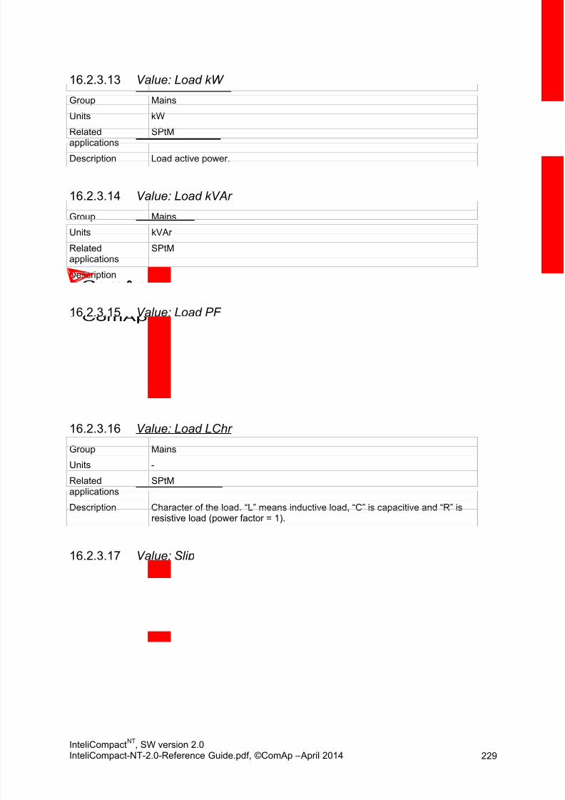
8/15/2019 InteliCompact NT 2.0 Reference Guide
http://slidepdf.com/reader/full/intelicompact-nt-20-reference-guide 229/287
InteliCompactNT
, SW version 2.0InteliCompact-NT-2.0-Reference Guide.pdf, ©ComAp – April 2014 229
Value: Load kW16.2.3.13
Group Mains
Units kW
Related
applications
SPtM
Description Load active power.
Value: Load kVAr16.2.3.14
Group Mains
Units kVAr
Relatedapplications
SPtM
Description Load reactive power.
Value: Load PF16.2.3.15
Group Mains
Units -
Relatedapplications
SPtM
Description Load power factor.
Value: Load LChr16.2.3.16
Group Mains
Units -
Relatedapplications
SPtM
Description Character of the load. “L” means inductive load, “C” is capacitive and “R” is resistive load (power factor = 1).
Value: Slip16.2.3.17Group Mains
Units Hz
Relatedapplications
All
Description Differential frequency between the gen-set and the mains.
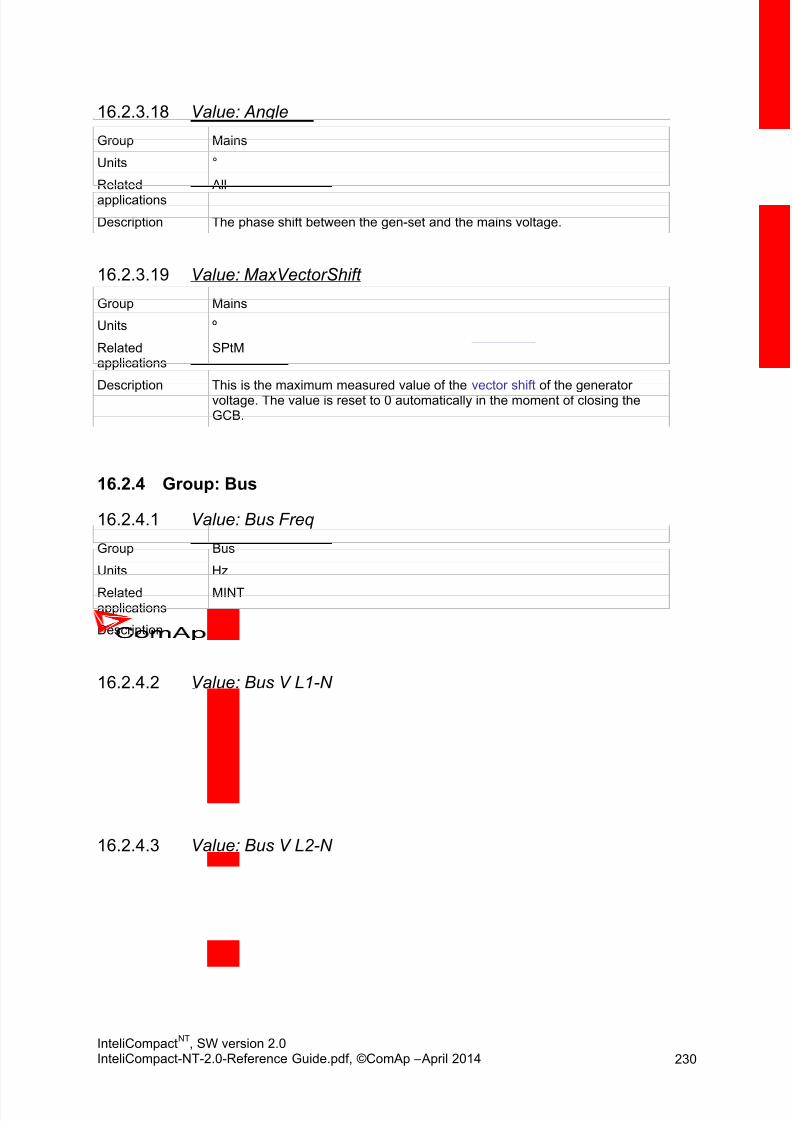
8/15/2019 InteliCompact NT 2.0 Reference Guide
http://slidepdf.com/reader/full/intelicompact-nt-20-reference-guide 230/287
InteliCompactNT
, SW version 2.0InteliCompact-NT-2.0-Reference Guide.pdf, ©ComAp – April 2014 230
Value: Angle16.2.3.18
Group Mains
Units °
Related
applications
All
Description The phase shift between the gen-set and the mains voltage.
Value: MaxVectorShift16.2.3.19
Group Mains
Units º
Relatedapplications
SPtM
Description This is the maximum measured value of the vector shift of the generatorvoltage. The value is reset to 0 automatically in the moment of closing theGCB.
16.2.4 Group: Bus
Value: Bus Freq16.2.4.1
Group Bus
Units Hz
Relatedapplications
MINT
Description Bus frequency taken from phase L3.
Value: Bus V L1-N16.2.4.2
Group Bus
Units V
Relatedapplications
MINT
Description Bus phase L1 voltage.
Value: Bus V L2-N16.2.4.3
Group Bus
Units V
Relatedapplications
MINT
Description Bus phase L2 voltage.

8/15/2019 InteliCompact NT 2.0 Reference Guide
http://slidepdf.com/reader/full/intelicompact-nt-20-reference-guide 231/287
InteliCompactNT
, SW version 2.0InteliCompact-NT-2.0-Reference Guide.pdf, ©ComAp – April 2014 231
Value: Bus V L3-N16.2.4.4
Group Bus
Units V
Related
applications
MINT
Description Bus phase L3 voltage.
Value: Bus V L1-L216.2.4.5
Group Bus
Units V
Relatedapplications
MINT
Description Bus phase L1 to phase L2 voltage.
Value: Bus V L2-L316.2.4.6
Group Bus
Units V
Relatedapplications
MINT
Description Bus phase L2 to phase L3 voltage.
Value: Bus V L3-L116.2.4.7
Group Bus
Units V
Relatedapplications
MINT
Description Bus phase L3 to phase L1 voltage.
Value: Slip16.2.4.8
Group Mains
Units Hz
Relatedapplications
MINT
Description Differential frequency between the gen-set and the mains.

8/15/2019 InteliCompact NT 2.0 Reference Guide
http://slidepdf.com/reader/full/intelicompact-nt-20-reference-guide 232/287
InteliCompactNT
, SW version 2.0InteliCompact-NT-2.0-Reference Guide.pdf, ©ComAp – April 2014 232
Value: Angle16.2.4.9
Group Mains
Units °
Related
applications
MINT
Description The phase shift between the gen-set and the mains voltage.
16.2.5 Group: Pwr Management
Value: Actual Reserve16.2.5.1
Group Power management
Units kW or % (depends on #PowerMgmtMode setpoint)
Relatedapplications
MINT
Description #PowerMgmtMode setpoint is set to ABS(kW):
This value represents the difference between the current load of the groupand the nominal capacity of the currently loaded gen-sets.
[]
#PowerMgmtMode setpoint is set to REL(%):
This value represents the difference between the actual relative load of thegroup and 100%.
∑ ∑ [] = Running NomPwr and = Running ActPwr .
Value: Running ActPwr16.2.5.2
Group Power management
Units kW
Relatedapplications
MINT
Description Sum of active power of all gen-sets within the group that are connected tothe bus and are performing the power management, i.e. that are in AUTmode and have power management enabled.

8/15/2019 InteliCompact NT 2.0 Reference Guide
http://slidepdf.com/reader/full/intelicompact-nt-20-reference-guide 233/287
InteliCompactNT
, SW version 2.0InteliCompact-NT-2.0-Reference Guide.pdf, ©ComAp – April 2014 233
Value: Running Q-Pwr16.2.5.3
Value: Running NomPwr16.2.5.4
Group Power management
Units kW
Relatedapplications
MINT
Description Sum of nominal power of all gen-sets within the group that are connected tothe bus and are performing the power management, i.e. that are in AUTmode and have power management enabled.
Value: Avail Nom Pwr16.2.5.5
Group Power management
Units kW
Relatedapplications
MINT
Description Sum of nominal load of all active gen-sets within the group.
Value: Priority16.2.5.6
Group Power management
Units -
Relatedapplications
MINT
Description This value shows the current priority number. If the binary input Top Priority is
active, the priority number will be 0, otherwise the value will correspond to thesetpoint Priority . See the chapter Power management for details.
Value: Act Pwr Band16.2.5.7
Group Power management
Range [units] -
Relatedapplications
MINT
Description The values show which gen-sets (controller CAN addresses) are running incurrent active power band.
Group Power management
Units kVAr
Related
applications
MINT
Description Sum of reactive power of all gen-sets within the group that are connected tothe bus and are performing the power management, i.e. that are in AUTmode and have power management enabled.
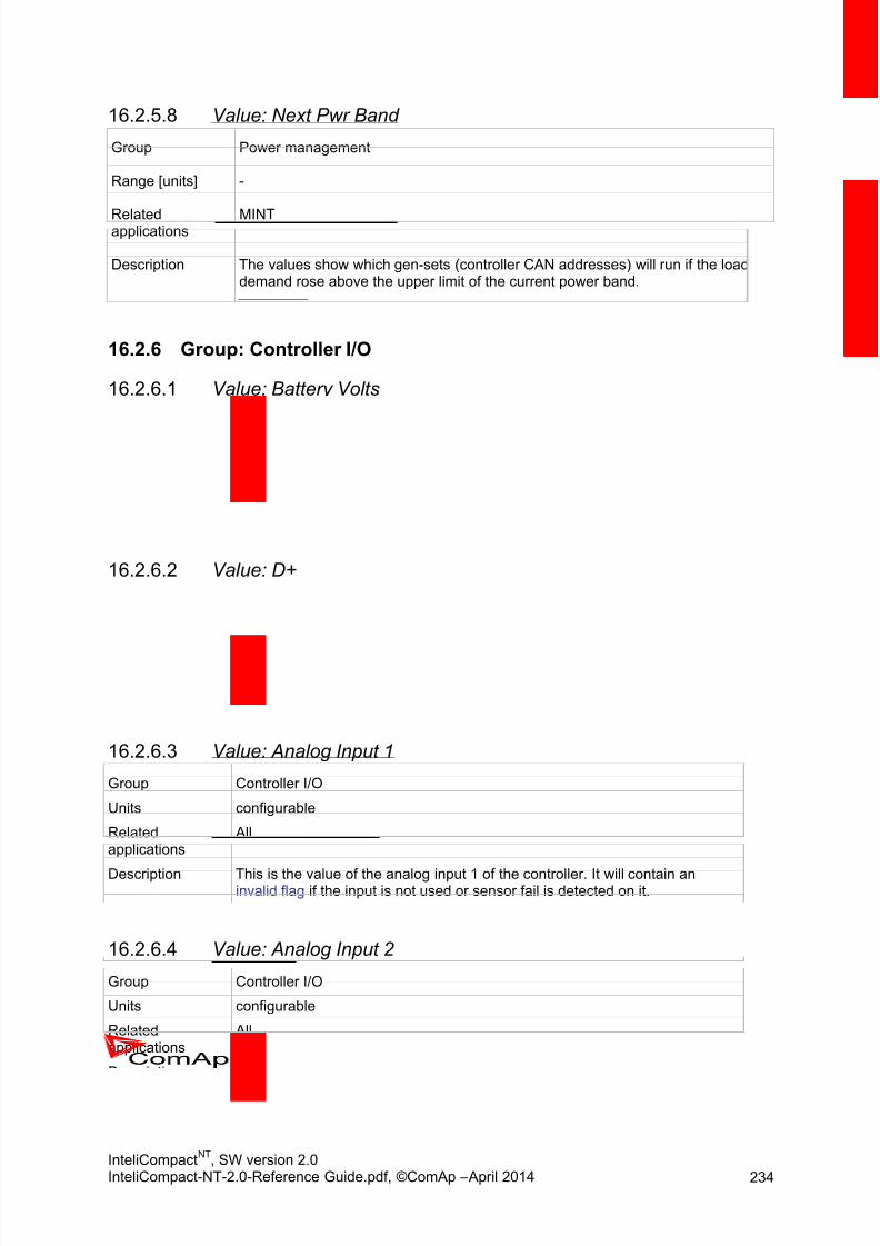
8/15/2019 InteliCompact NT 2.0 Reference Guide
http://slidepdf.com/reader/full/intelicompact-nt-20-reference-guide 234/287
InteliCompactNT
, SW version 2.0InteliCompact-NT-2.0-Reference Guide.pdf, ©ComAp – April 2014 234
Value: Next Pwr Band16.2.5.8
Group Power management
Range [units] -
Relatedapplications
MINT
Description The values show which gen-sets (controller CAN addresses) will run if the loaddemand rose above the upper limit of the current power band.
16.2.6 Group: Controller I/O
Value: Battery Volts16.2.6.1
Group Controller I/O
Units V
Relatedapplications
All
Description Controller supply voltage.
Value: D+16.2.6.2
Group Controller I/O
Units V
Relatedapplications
All
Description D+ terminal voltage.
Value: Analog Input 116.2.6.3
Group Controller I/O
Units configurable
Relatedapplications
All
Description This is the value of the analog input 1 of the controller. It will contain aninvalid flag if the input is not used or sensor fail is detected on it.
Value: Analog Input 216.2.6.4
Group Controller I/O
Units configurable
Relatedapplications
All
Description This is the value of the analog input 2 of the controller. It will contain an
invalid flag if the input is not used or sensor fail is detected on it.

8/15/2019 InteliCompact NT 2.0 Reference Guide
http://slidepdf.com/reader/full/intelicompact-nt-20-reference-guide 235/287
InteliCompactNT
, SW version 2.0InteliCompact-NT-2.0-Reference Guide.pdf, ©ComAp – April 2014 235
Value: Analog Input 316.2.6.5
Group Controller I/O
Units configurable
Related
applications
All
Description This is the value of the analog input 3 of the controller. It will contain aninvalid flag if the input is not used or sensor fail is detected on it.
Value: Bin Inputs16.2.6.6
Group Controller I/O
Units -
Relatedapplications
All
Description This is a bit array containing the status of the physical binary inputs of thecontroller. Bit0 represents BI1, bit1 represents BI2, etc.
NOTE: In LiteEdit and on the controller screen this value is displayed in “normalorder ”, i.e. BI1 in the leftmost position
Value: Bin Outputs16.2.6.7
Group Controller I/O
Units -
Relatedapplications
All
Description This is a bit array containing the status of the physical binary outputs of thecontroller. Bit0 represents BO1, bit1 represents BO2, etc.
NOTE: In LiteEdit and on the controller screen this value is displayed in “normalorder ”, i.e. BO1 in the leftmost position.
Value: Speed Gov Out16.2.6.8
Group Controller I/O
Units V
Relatedapplications
All
Description This is the actual voltage on the speed governor output of the controller. Inthe event that the output is switched to PWM mode, the relation is10V ~ 100% PWM.
Value: AVRi Output16.2.6.9
Group Controller I/O
Units %

8/15/2019 InteliCompact NT 2.0 Reference Guide
http://slidepdf.com/reader/full/intelicompact-nt-20-reference-guide 236/287
InteliCompactNT
, SW version 2.0InteliCompact-NT-2.0-Reference Guide.pdf, ©ComAp – April 2014 236
Relatedapplications
All
Description This is the actual PWM percentage on the AVRi output of the controller.
Value: GSM SignalLvl16.2.6.10Group Controller I/O
Units %
Relatedapplications
All
Description IL-NT-GPRS module shows the strength of the GSM signal. It is a relativevalue helping to find the best signal and for troubleshooting cases.
Value: GSM ErrorRate16.2.6.11
Group Controller I/O
Units -
Relatedapplications
All
Description IL-NT-GPRS module shows this information for relative evaluation of signalquality. The lower value, the higher the signal quality.
Value: GSM Diag Code16.2.6.12
Group Controller I/O
Units -
Relatedapplications
All
Description Diagnostic code for the IL-NT-GPRS modem. Standard GSM modems usuallysupport this value as well. Helps in troubleshooting.
T ABLE OF DIAGNOSTIC CODES
Code Description
0 OK. No error.
1 Not possible to hang up.
2IL-NT-base is switched off
3 IL-NT-GPRS is switched on
4 IL-NT-GPRS – error in initialization
5 IL-NT-GPRS – not possible to set the APN
6 IL-NT-GPRS – not possible to connect to GPRS network
7 IL-NT-GPRS – not possible to retrieve IP address
8 IL-NT-GPRS – not accepted DNS IP address
9 Error in modem detection
10 Error in initialization of analog modem
11SIM card is locked (Possibly PIN code required, PIN needs to be deactivated) orunknown status of SIM locking
12 No GSM signal
13 Not possible to read the SIM card parameters
14 GSM modem did not accept particular initialization command, possibly caused by

8/15/2019 InteliCompact NT 2.0 Reference Guide
http://slidepdf.com/reader/full/intelicompact-nt-20-reference-guide 237/287
InteliCompactNT
, SW version 2.0InteliCompact-NT-2.0-Reference Guide.pdf, ©ComAp – April 2014 237
locked SIM card
15 Unknown modem
16 Bad answer to complement initialization string
17 Not possible to read GSM signal strength
18 CDMA modem not detected
19 No CDMA network
20 Unsuccessful registration to CDMA network
255 Only running communication is needed to indicate
Value: AirGate Diag16.2.6.13
Group Controller I/O
Units -
Relatedapplications
All
Description Diagnostic code for AirGate connection. Helps in troubleshooting.
T ABLE OF DIAGNOSTIC CODES:
Code Description
1 Controller registered, waiting for authorization
2 Not possible to register, controller blacklisted
3 Not possible to register, server has no more capacity
4 Not possible to register, other reason
5 Controller registered and authorized
Value: AirGate ID16.2.6.14
Group Controller I/O
Units -
Relatedapplications
All
Description Identification name generated by AirGate server for the purpose ofestablishing communication via WebSupervisor , LiteEdit or InteliMonitor .
Value: Modem Status16.2.6.15
Group Controller I/O
Units -
Relatedapplications
All
Description Status of the modem.
“--------“ After controller initialization
“Trying” Modem active. Trying to establish connection.
“Ready” Modem ready. Communication with modem is OK.

8/15/2019 InteliCompact NT 2.0 Reference Guide
http://slidepdf.com/reader/full/intelicompact-nt-20-reference-guide 238/287
InteliCompactNT
, SW version 2.0InteliCompact-NT-2.0-Reference Guide.pdf, ©ComAp – April 2014 238
16.2.7 Group: Extension I/O
Value: IOM AI116.2.7.1
Group Extension I/OUnits configurable
Relatedapplications
All
Description This is the value of the analog input 1 of the IOM/PTM extension module. Itwill contain an invalid flag if the input or module is not used or sensor fail isdetected on it.
Value: IOM AI216.2.7.2
Group Extension I/O
Units configurable
Relatedapplications
All
Description This is the value of the analog input 2 of the IOM/PTM extension module. Itwill contain an invalid flag if the input or module is not used or sensor fail isdetected on it.
Value: IOM AI316.2.7.3
Group Extension I/O
Units configurable
Relatedapplications
All
Description This is the value of the analog input 3 of the IOM/PTM extension module. Itwill contain an invalid flag if the input or module is not used or sensor fail isdetected on it.
Value: IOM AI416.2.7.4
Group Extension I/O
Units configurable
Relatedapplications
All
Description This is the value of the analog input 4 of the IOM/PTM extension module. Itwill contain an invalid flag if the input or module is not used or sensor fail isdetected on it.

8/15/2019 InteliCompact NT 2.0 Reference Guide
http://slidepdf.com/reader/full/intelicompact-nt-20-reference-guide 239/287
InteliCompactNT
, SW version 2.0InteliCompact-NT-2.0-Reference Guide.pdf, ©ComAp – April 2014 239
Value: IOM Bin Inp16.2.7.5
Group Extension I/O
Units -
Related
applications
All
Description This is a bit array containing the status of physical binary inputs of theIOM/PTM extension module. Bit0 represents BI1, bit1 represents BI2, etc.
NOTE: In LiteEdit and on the controller screen this value is displayed in “normalorder ”, i.e. BI1 in the leftmost position.
Value: ExtM Bin Inp16.2.7.6
Group Extension I/O
Units -
Relatedapplications
All
Description This is a bit array containing the status of physical binary inputs of theextension plugin module. Bit0 represents ExM BI1, bit1 represents ExM BI2,etc.
NOTE: In the LiteEdit and on the controller screen this value is displayed in “normalorder ”, i.e. ExM BI1 in the leftmost position.
Value: RA Bin Out16.2.7.7
Group Extension I/O
Units -
Relatedapplications
All
Description This is a bit array containing the status of the LED indicators of the RA15module. Bit0 represents the top left LED, bit14 represents the bottom rightLED.
NOTE: In LiteEdit and on the controller screen this value is displayed in “normal
order ”, i.e. bit0 in the leftmost position.

8/15/2019 InteliCompact NT 2.0 Reference Guide
http://slidepdf.com/reader/full/intelicompact-nt-20-reference-guide 240/287
InteliCompactNT
, SW version 2.0InteliCompact-NT-2.0-Reference Guide.pdf, ©ComAp – April 2014 240
Value: IOM Bin Out16.2.7.8
Group Extension I/O
Units -
Related
applications
All
Description This is a bit array containing the status of physical binary outputs of theIOM/PTM module. Bit0 represents BO1, bit1 represents BO2, etc.
NOTE: In LiteEdit and on the controller screen this value is displayed in “normalorder ”, i.e. BO1 in the leftmost position.
16.2.8 Group: Statistics
Value: Energy kWh16.2.8.1Group Statistics
Units kWh
Relatedapplications
All
Description Active energy counter.
Value: Energy kVArh16.2.8.2
Group Statistics
Units kVArh
Relatedapplications
All
Description Reactive energy counter.
Value: Run Hours16.2.8.3
Group Statistics
Units h
Relatedapplications
All
Description Engine operation hours counter. If an ECU is configured and it providesengine hours value, the value is taken from the ECU. If the value is notavailable from the ECU or if an ECU is not configured, the engine hours areincremented in the controller while the engine is running.

8/15/2019 InteliCompact NT 2.0 Reference Guide
http://slidepdf.com/reader/full/intelicompact-nt-20-reference-guide 241/287
InteliCompactNT
, SW version 2.0InteliCompact-NT-2.0-Reference Guide.pdf, ©ComAp – April 2014 241
Value: Num Starts16.2.8.4
Group Statistics
Units -
Related
applications
All
Description Engine start commands counter. The counter is increased by 1 even if theparticular start command will take more than one attempt.
Value: Maintenance16.2.8.5
Group Statistics
Units h
Relatedapplications
All
Description Countdown until next maintenance. Initial value can be set in Engine Protect –WrnMaintenace.
Value: Num E-Stops16.2.8.6
Group Statistics
Units -
Relatedapplications
All
Description Emergency stop alarms counter.
Value: Shutdowns16.2.8.7
Group Statistics
Units -
Relatedapplications
All
Description Shutdown alarms counter. This counter counts all occurrences of a shutdownalarm, not only real shutdowns of the gen-set, i.e. the counter is increased by2 if two shutdown alarms appear simultaneously.

8/15/2019 InteliCompact NT 2.0 Reference Guide
http://slidepdf.com/reader/full/intelicompact-nt-20-reference-guide 242/287
InteliCompactNT
, SW version 2.0InteliCompact-NT-2.0-Reference Guide.pdf, ©ComAp – April 2014 242
Value: TotFuelConsum16.2.8.8
Group Statistics
Units L
Related
applications
All
Description Value containing total amount of consumed fuel by engine. The controllerautomatically updates this value every 30 s. The controller can calculate it inthree ways:
- Direct reading from ECU- Calculation based on actual fuel consumption reading from ECU- Calculation from fuel level drop in tank (using Fuel Level AI +
FuelTankVolume setpoint)
NOTE:The accuracy of Total Fuel Consumption depends on the precision of ECUvalues or precision of FuelTankVolume and fuel level sensor.
Value: PerTotFuelCons16.2.8.9
Group Statistics
Units L
Relatedapplications
All
Description Value of Period Fuel Consumption is calculated from the Total FuelConsumption. It can be reset by the PerFuelConsRes binary input.
16.2.9 Group: Date/Time
Value: Time16.2.9.1
Group Info
Units hh:mm:ss
Relatedapplications
All
Description Shows setup time.
Value: Date16.2.9.2
Group Info
Units dd.mm.yyyy
Relatedapplications
All
Description Shows setup date.

8/15/2019 InteliCompact NT 2.0 Reference Guide
http://slidepdf.com/reader/full/intelicompact-nt-20-reference-guide 243/287
InteliCompactNT
, SW version 2.0InteliCompact-NT-2.0-Reference Guide.pdf, ©ComAp – April 2014 243
16.2.10 Group: Info
Value: Engine State16.2.10.1
Group Info
Units -Relatedapplications
All
Description The value contains the numeric code of the “engine state” message which isshown on the main screen of the controller.
The assignment of texts to the codes can be obtained using LiteEdit. Openany connection (also offline with a previously saved archive) and go to the
menu Controller -> Generate CFG image. The resulting file will contain the
assignment of texts to the codes.
Value: Breaker State16.2.10.2Group Info
Units -
Relatedapplications
All
Description The value contains the numeric code of the “breaker state” message which isshown on the main screen of the controller.
The assignment of texts to the codes can be obtained using LiteEdit. Openany connection (also offline with a previously saved archive) and go to the
menu Controller -> Generate CFG image. The resulting file will contain the
assignment of texts to the codes.
Value: Timer Text16.2.10.3
Group Info
Units -
Relatedapplications
All
Description The value contains the numeric code of the “Current process timer ” textwhich is shown on the main screen of the controller.
The assignment of texts to the codes can be obtained using LiteEdit. Openany connection (also offline with a previously saved archive) and go to the
menu Controller -> Generate CFG image. The resulting file will contain the
assignment of texts to the codes.

8/15/2019 InteliCompact NT 2.0 Reference Guide
http://slidepdf.com/reader/full/intelicompact-nt-20-reference-guide 244/287
InteliCompactNT
, SW version 2.0InteliCompact-NT-2.0-Reference Guide.pdf, ©ComAp – April 2014 244
Value: Timer Value16.2.10.4
Group Info
Units s
Related
applications
All
Description The value contains the "Current process timer" value which is shown on themain screen of the controller.
Value: FW Version16.2.10.5
Group Info
Units -
Relatedapplications
All
Description Major and minor firmware version number. This value does not contain therelease version number.
Value: FW Branch16.2.10.6
Group Info
Units -
Relatedapplications
All
Description Firmware branch code. Contains 1 in the case of standard branches.
Value: PasswordDecode16.2.10.7
Group Info
Units -
Relatedapplications
All
Description This value contains a number which can be used for retrieving a lostpassword. Send this number together with the controller serial number toyour distributor if you have lost your password.
Value: CAN1616.2.10.8
Group Info
Units -
Relatedapplications
MINT
Description Each bit of this value shows if a controller with the corresponding address isfound on the bus. Bit 0 represents address 1 etc.

8/15/2019 InteliCompact NT 2.0 Reference Guide
http://slidepdf.com/reader/full/intelicompact-nt-20-reference-guide 245/287
InteliCompactNT
, SW version 2.0InteliCompact-NT-2.0-Reference Guide.pdf, ©ComAp – April 2014 245
Value: CAN3216.2.10.9
Group Info
Units -
Related
applications
MINT
Description Each bit of this value shows if a controller with the corresponding address isfound on the bus. Bit 0 represents address 16 etc.
Value: GensLoaded1616.2.10.10
Group Info
Units -
Relatedapplications
MINT
Description Each bit if set represents gen-set with its GCB closed.
Value: GensLoaded3216.2.10.11
Group Info
Units -
Relatedapplications
MINT
Description Each bit if set represents gen-set with its GCB closed.
16.3 Table of binary inpu t func t ions
16.3.1 Common functions
Binary input: GCB Feedback16.3.1.1
Relatedapplications
All
Description This is an input from the generator circuit breaker or contactor auxiliarycontact. If the input is active, the controller will consider the GCB as closedand vice versa. If the GCB is not in the expected position, the alarm GCB Fail will occur.

8/15/2019 InteliCompact NT 2.0 Reference Guide
http://slidepdf.com/reader/full/intelicompact-nt-20-reference-guide 246/287
InteliCompactNT
, SW version 2.0InteliCompact-NT-2.0-Reference Guide.pdf, ©ComAp – April 2014 246
Binary input: MCB Feedback16.3.1.2
Relatedapplications
All
Description This is an input from the Mains circuit breaker or contactor auxiliary contact. Ifthe input is active, the controller will consider the MCB as closed and vice
versa. According to the MCB position the controller differentiates betweenParallel to Mains operation and Island operation.
SPtM, MainsCompact: If the MCB is not in the expected position, the alarmMCB Fail will occur.
Binary input: Emergency Stop16.3.1.3
Relatedapplications
All
Description This input will activate the built-in Emergency Stop alarm. It is recommended
to use the “NC” button for this input because of safety reasons.CAUTION! This is a software function only. See the chapter Emergency stop in theInstallation section of this manual if a “hard-wired” emergency stop function isneeded.
Binary input: Sd Override16.3.1.4
Relatedapplications
All
Description If this input is active, all red alarms except emergency stop and overspeed
are suppressed. The suppressed alarms will be displayed in the alarmlist, butthey will not take effect regarding the gen-set control.
NOTE: This input is designed to be used only while the gen-set is supplying pumpsfor automatic fire-extinguishing devices (sprinklers) or in other situations,where providing power is more important than protecting the gen-set.
CAUTION! Misuse of this input can cause damage to the gen-set!
Binary input: Access Lock16.3.1.5
Relatedapplications
All
Description If this input is active, then change of all setpoints and controller mode isdisabled, even if the password is entered.
NOTE: Active access lock is indicated by an “L” letter in the upper right corner of thecontroller main screen.
NOTE: This input does not disable remote changes of setpoints i.e. from LiteEdit.

8/15/2019 InteliCompact NT 2.0 Reference Guide
http://slidepdf.com/reader/full/intelicompact-nt-20-reference-guide 247/287
InteliCompactNT
, SW version 2.0InteliCompact-NT-2.0-Reference Guide.pdf, ©ComAp – April 2014 247
Binary input: Remote OFF16.3.1.6
Relatedapplications
All
Description This input switches the controller into OFF mode independent of which modeis selected by the mode selector on the controller main screen. Learn more
about controller modes in the Operating modes chapter.
If multiple “remote mode” inputs are active at the same time, the highestpriority has Remote OFF, then Remote TEST, Remote MAN and Remote AUT.
Binary input: Remote MAN16.3.1.7
Relatedapplications
All
Description This input switches the controller into MAN mode independent of which mode
is selected by the mode selector on the controller main screen. Learn moreabout controller modes in the Operating modes chapter.
If multiple “remote mode” inputs are active at the same time, the highestpriority is held by Remote OFF, then Remote TEST, Remote MAN andRemote AUT.
Binary input: Remote AUT16.3.1.8
Relatedapplications
All
Description This input switches the controller into AUT mode independent of which mode
is selected by the mode selector on the controller main screen. Learn moreabout controller modes in the Operating modes chapter.
If multiple “remote mode” inputs are active at the same time, the highestpriority is held by Remote OFF, then Remote TEST, Remote MAN andRemote AUT.
Binary input: RemControlLock16.3.1.9
Relatedapplications
All
Description If the input is active, the controller will not accept any actions regarding thegen-set control – e.g. writing of commands and setpoint changes – fromremote communication interfaces (RS232, Modem, Modbus, iG-IB, i-LB).
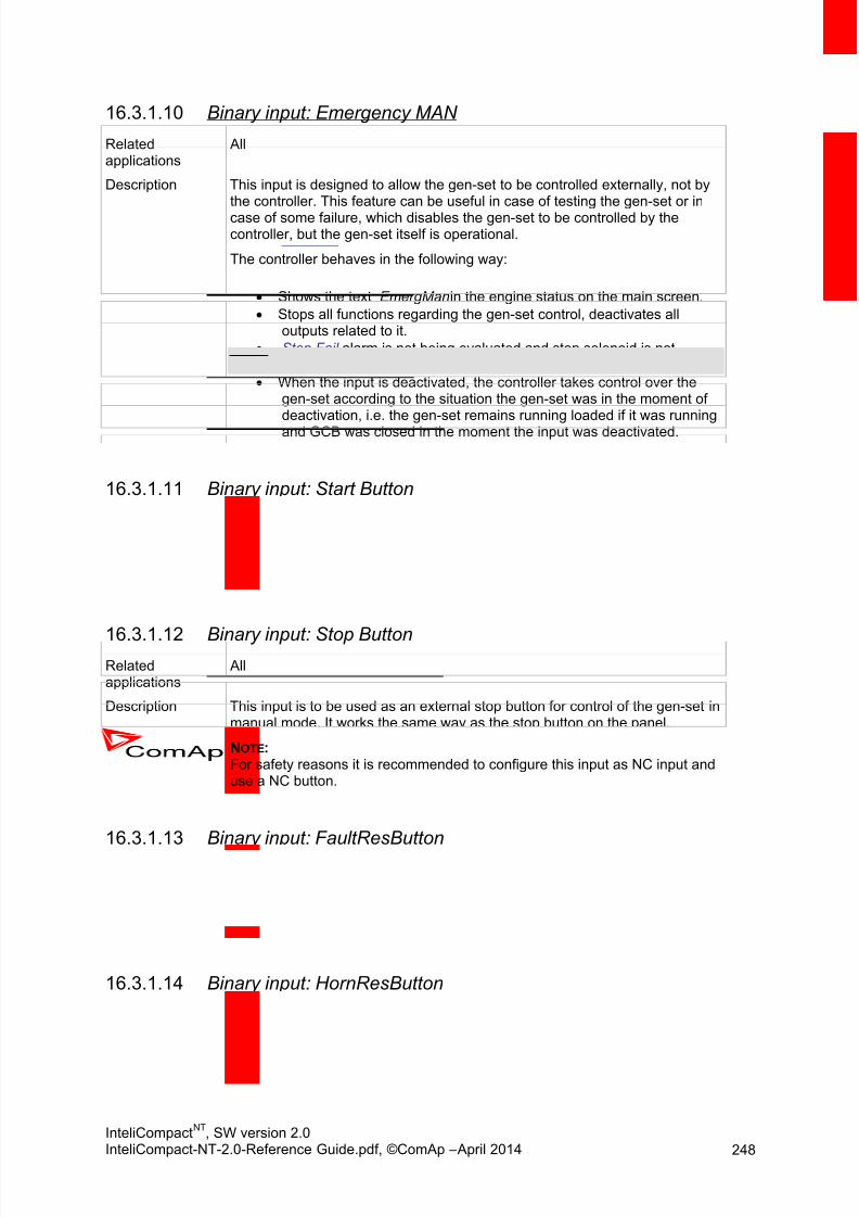
8/15/2019 InteliCompact NT 2.0 Reference Guide
http://slidepdf.com/reader/full/intelicompact-nt-20-reference-guide 248/287
InteliCompactNT
, SW version 2.0InteliCompact-NT-2.0-Reference Guide.pdf, ©ComAp – April 2014 248
Binary input: Emergency MAN16.3.1.10
Relatedapplications
All
Description This input is designed to allow the gen-set to be controlled externally, not bythe controller. This feature can be useful in case of testing the gen-set or in
case of some failure, which disables the gen-set to be controlled by thecontroller, but the gen-set itself is operational.
The controller behaves in the following way:
Shows the text EmergMan in the engine status on the main screen.
Stops all functions regarding the gen-set control, deactivates alloutputs related to it.
Stop Fail alarm is not being evaluated and stop solenoid is notactivated if nonzero speed is detected.
When the input is deactivated, the controller takes control over thegen-set according to the situation the gen-set was in the moment ofdeactivation, i.e. the gen-set remains running loaded if it was running
and GCB was closed in the moment the input was deactivated.
Binary input: Start Button16.3.1.11
Relatedapplications
All
Description This input is to be used as an external start button for control of the gen-set inmanual mode. It works the same way as the start button on the panel.
Binary input: Stop Button16.3.1.12Relatedapplications
All
Description This input is to be used as an external stop button for control of the gen-set inmanual mode. It works the same way as the stop button on the panel.
NOTE: For safety reasons it is recommended to configure this input as NC input anduse a NC button.
Binary input: FaultResButton16.3.1.13
Relatedapplications
All
Description This input is to be used as an external fault reset button. It works the sameway as the fault reset button on the panel.
Binary input: HornResButton16.3.1.14
Relatedapplications
All
Description This input is to be used as an external horn reset button. It works the sameway as the horn reset button on the panel.

8/15/2019 InteliCompact NT 2.0 Reference Guide
http://slidepdf.com/reader/full/intelicompact-nt-20-reference-guide 249/287
InteliCompactNT
, SW version 2.0InteliCompact-NT-2.0-Reference Guide.pdf, ©ComAp – April 2014 249
Binary input: GCB Button16.3.1.15
Relatedapplications
All
Description This input is to be used as an external GCB button for control of the gen-setin manual mode. It works the same way as the GCB button on the panel.
Binary input: ForwSyncDisabl16.3.1.16
Relatedapplications
All
Description If the input is active, the controller will not continue to synchronize afterMinStabTime elapsed even in AUT mode. If an island condition occurs(mains fails), the gen-set will take the island load.
Binary input: NeutralCB fdb16.3.1.17Relatedapplications
All
Description Use this input to detect whether the Neutral circuit breaker is open or closed.See also setpoint #Neutral cont and binary output Neutral CB C/O.
Binary input: PerFuelConsRes16.3.1.18
Relatedapplications
All
Description If the input is active, the controller will not continue to synchronize afterMinStabTime elapsed even in AUT mode. If an island condition occurs(mains fails), the gen-set will take the island load.
16.3.2 MINT specific
Binary input: Sys Start/Stop16.3.2.1
Relatedapplications
MINT
Description This input activates the power management in the controller. If this input isnot active, the gen-set is stopped in AUT mode and does not take part withinthe power management of the group.
NOTE: In most cases this input is wired parallel into all controllers within the group toactivate and deactivate the whole group. If you want to deactivate oneparticular gen-set, switch it out from AUT mode.
NOTE: If the power management is disabled by the Pwr Management setpoint, thegen-set is started and stopped only according to this input.

8/15/2019 InteliCompact NT 2.0 Reference Guide
http://slidepdf.com/reader/full/intelicompact-nt-20-reference-guide 250/287
InteliCompactNT
, SW version 2.0InteliCompact-NT-2.0-Reference Guide.pdf, ©ComAp – April 2014 250
Binary input: Load Reserve 216.3.2.2
Relatedapplications
MINT
Description This input selects the currently used pair of reserves for the powermanagement. If the input is active, the pair LoadResStrt 2 and LoadResStop
2 is active instead of LoadResStrt 1 and LoadResStop 1.
Binary input: Min Run Power16.3.2.3
Relatedapplications
MINT
Description Use this input if you need to ensure that the nominal power of loaded gen-sets does not drop below the value of Min Run Power even if the reserve for
stop is fulfilled.
Binary input: Top Priority16.3.2.4
Relatedapplications
MINT
Description If this input is active, the controller will have the highest priority in the groupindependent of the setpoint Priority . Setpoint is evaluated only in LoadDemand Star/Stop regime.
16.3.3 SPtM specific
Binary input: Rem Start/Stop16.3.3.1
Relatedapplications
SPtM
Description Use this input to start and stop the gen-set in AUT mode.
Binary input: Remote TEST16.3.3.2
Relatedapplications
SPtM
Description This input switches the controller into TEST mode independent of whichmode is selected by the mode selector on the controller main screen. Learnmore about controller modes in the Operating modes chapter.
If multiple “remote mode” inputs are active at the same time, the highestpriority is held by Remote OFF, then Remote TEST, Remote MAN andRemote AUT.
Binary input: Rem TEST OnLd16.3.3.3
Relatedapplications
SPtM
Description This input switches the controller into TEST mode like Remote TEST , butforces the controller to take the load, i.e. perform the test on load procedure.

8/15/2019 InteliCompact NT 2.0 Reference Guide
http://slidepdf.com/reader/full/intelicompact-nt-20-reference-guide 251/287
InteliCompactNT
, SW version 2.0InteliCompact-NT-2.0-Reference Guide.pdf, ©ComAp – April 2014 251
Binary input: RevSyncDisable16.3.3.4
Relatedapplications
SPtM
Description If the input is active, the controller will not perform reverse synchronizing when the mains have returned, but performs a changeover instead.
Binary input: MCB Button16.3.3.5
Relatedapplications
SPtM
Description This input is to be used as an external MCB button for control of the breakerin manual mode. It works the same way as the MCB button on the panel.
Binary input: Ext MF Relay16.3.3.6
Relatedapplications
SPtM
Description This input can be used for connecting an external mains protection relay. Ifthe input is activated, the controller will consider the mains to have failed andwill perform all appropriate actions.
Binary input: MainsFailBlock16.3.3.7
Relatedapplications
SPtM
Description If the input is active, the gen-set will not start after the mains fail although the
controller is in AUT mode. If the gen-set is already running and the input hasbeen activated, the timer ReturtnDel starts to count then the GCB is opened,gen-set goes to cooling procedure and stops The input simulates healthymains.
NOTE:THE MCB WILL CLOSE WHILE THE GCB IS OPENING !
16.4 Table of binary outp ut func t ions
16.4.1 Common functions
Binary output: Starter16.4.1.1
Relatedapplications
All
Description This output is dedicated for starter motor control.
NOTE: Learn more about starting procedure in the chapter Engine start.

8/15/2019 InteliCompact NT 2.0 Reference Guide
http://slidepdf.com/reader/full/intelicompact-nt-20-reference-guide 252/287
InteliCompactNT
, SW version 2.0InteliCompact-NT-2.0-Reference Guide.pdf, ©ComAp – April 2014 252
Binary output: Battery B16.4.1.2
Relatedapplications
All
Description This output should be used in case that two batteries for starting are used.Batter B output switches between two alternative sources of power, battery A
and battery B. Battery B output is opened for the first cranking cycle which isdesignated for Battery A and closes for the second cranking cycle which isdesignated for Battery B (in case that two batteries for cranking are used).
Starter
(=Cranking)
Battery B
1st attempt 2nd attemptCrank pause
Battery A in use Battery B in use
Binary output: Fuel Solenoid16.4.1.3Relatedapplications
All
Description This output is dedicated to controlling the fuel solenoid (valve). The output isclosed 0.5 before Starter and remains closed all the time the gen-set shallrun.
NOTE: Learn more about starting procedure in the chapter Engine start.
Binary output: Stop Solenoid16.4.1.4
Relatedapplications
All
Description This output is dedicated to control the stop solenoid (valve). The output isclosed in the moment when the gen-set shall stop and remains active untilthe gen-set is stopped, but at least for time period of Stop Time. If the Stop
time has elapsed and the engine is still not stopped, the stop solenoid is de-energized for 5 and then energized again for max. Stop time and this repeatsuntil the engine is stopped.
NOTE: Learn more about evaluation of stopped engine in the chapter Stopped gen-set evaluation.
Binary output: Stop Pulse16.4.1.5
Relatedapplications
All
Description This output will give a 1 pulse whenever a stop command is issued to thegen-set, i.e. when the binary output Stop Solenoid is activated.

8/15/2019 InteliCompact NT 2.0 Reference Guide
http://slidepdf.com/reader/full/intelicompact-nt-20-reference-guide 253/287
InteliCompactNT
, SW version 2.0InteliCompact-NT-2.0-Reference Guide.pdf, ©ComAp – April 2014 253
Binary output: Ignition16.4.1.6
Relatedapplications
All
Description This output is dedicated to controlling the ignition at a gas engine. The outputis closed together with Fuel Solenoid in the moment the gen-set reaches
30RPM during cranking. The output is opened when the gen-set hasstopped.
Binary output: Prestart16.4.1.7
Relatedapplications
All
Description This output can be used for control of any device, which has to be activated just before start, i.e. glow plugs. The output is closed for time period ofPrestart Time prior to activation of the starter motor and remains closedduring cranking and also during pause between cranking attempts.
Binary output: Cooling Pump16.4.1.8
Relatedapplications
All
Description This output is dedicated for coolant pump control. It is closed in the momentthe gen-set is started and remains closed until the gen-set is stopped.
Binary output: Idle/Nominal16.4.1.9
Relatedapplications
All
Description This output is used for switching between idle speed and nominal speed ofthe engine during the startup phase, if this feature (input) is available on theparticular engine. In the case of some EFI engines, the idle/nominal switchingis performed over the communication bus.
Binary output: Alarm16.4.1.10
Relatedapplications
All
Description The output is designed to be used as external alarm indication such as a redbulb in the control room etc. The output is active when at least oneunconfirmed alarm is present in the alarmlist.

8/15/2019 InteliCompact NT 2.0 Reference Guide
http://slidepdf.com/reader/full/intelicompact-nt-20-reference-guide 254/287
InteliCompactNT
, SW version 2.0InteliCompact-NT-2.0-Reference Guide.pdf, ©ComAp – April 2014 254
Binary output: Horn16.4.1.11
Relatedapplications
All
Description The output designed to be used for acoustic indication of a newly appearedalarm. The output is activated each time a new alarm has appeared and
remains active until one of the following events occurs:
Fault reset is pressed
Horn reset is pressed
Horn Timeout has elapsed
Binary output: Fault Reset16.4.1.12
Relatedapplications
All
Description The output is a copy of Fault Reset button on controller and binary input
FaultResButton.
Binary output: GCB Close/Open16.4.1.13
Relatedapplications
All
Description This output is to be used for a contactor control in case a contactor is used inthe GCB position. See the chapter Circuit breakers for details about alloutputs available for generator/mains power switches.
Binary output: GCB ON Coil16.4.1.14
Relatedapplications
All
Description This output is to be used for control of the ON coil of the generator circuitbreaker. See the chapter Circuit breakers for details about all outputsavailable for generator/mains power switches.
Binary output: GCB OFF Coil16.4.1.15
Relatedapplications
All
Description This output is to be used for control of the OFF coil of the generator circuitbreaker. See the chapter Circuit breakers for details about all outputsavailable for generator/mains power switches.
Binary output: GCB UV Coil16.4.1.16
Relatedapplications
All
Description This output is to be used for opening the generator circuit breaker via theundervoltage coil. See the chapter Circuit breakers for details about alloutputs available for generator/mains power switches.

8/15/2019 InteliCompact NT 2.0 Reference Guide
http://slidepdf.com/reader/full/intelicompact-nt-20-reference-guide 255/287
InteliCompactNT
, SW version 2.0InteliCompact-NT-2.0-Reference Guide.pdf, ©ComAp – April 2014 255
Binary output: Speed Up16.4.1.17
Relatedapplications
All
Description This output together with the complementary output Speed Down is designedfor speed and power control at gen-sets, where the governor does not
support analog control. The outputs are also used for direct control of a gasthrottle at asynchronous gen-sets.
NOTE: Droop function is required when these outputs are used for power controlthrough a governor.
Binary output: Speed Down16.4.1.18
Relatedapplications
All
Description This output together with the complementary output Speed Up is designed forspeed and power control at gen-sets, where the governor does not supportanalog control. The outputs are also used for direct control of a gas throttle atasynchronous gen-sets.
NOTE: Droop function is required when these outputs are used for power controlthrough a governor.
Binary output: AVR Up16.4.1.19
Related
applications
All
Description This output together with the complementary output AVR Down is designedfor voltage and power factor control at gen-sets, where the AVR does notsupport analog control.
NOTE: Droop function is required when these outputs are used for power factorcontrol.
Binary output: AVR Down16.4.1.20
Related
applications
All
Description This output together with the complementary output AVR Up is designed forvoltage and power factor control at gen-sets, where the AVR does notsupport analog control.
NOTE: Droop function is required when these outputs are used for power factorcontrol.

8/15/2019 InteliCompact NT 2.0 Reference Guide
http://slidepdf.com/reader/full/intelicompact-nt-20-reference-guide 256/287
InteliCompactNT
, SW version 2.0InteliCompact-NT-2.0-Reference Guide.pdf, ©ComAp – April 2014 256
Binary output: Ready To Load16.4.1.21
Relatedapplications
All
Description The output is closed whenever the GCB is closed or can be closed. Detailsabout conditions when the GCB can be closed are available in the chapter
Connecting to the load.
Binary output: Synchronizing16.4.1.22
Relatedapplications
All
Description The output is closed during forward or reverse synchronizing.
Binary output: Running16.4.1.23
Relatedapplications
All
Description The output is designed to be used as an indication that the gen-set isrunning. It is activated at the moment the gen-set has been started and theidle period has elapsed. It remains active until stop command is issued.
Binary output: Loaded16.4.1.24
Relatedapplications
All
Description The output is closed whenever the GCB is closed except the unloading phaseprior to opening the GCB.
Binary output: Unloading16.4.1.25
Relatedapplications
All
Description The output is closed during the unloading phase (ramping the power down)prior to opening the GCB. More detailed description is available in the chapterParallel to mains operation.
Binary output: AnalogSwitch 116.4.1.26
Relatedapplications
All
Description This is an output from the Analog switch 1.
Binary output: AnalogSwitch 216.4.1.27
Relatedapplications
All
Description This is an output from the Analog switch 2.

8/15/2019 InteliCompact NT 2.0 Reference Guide
http://slidepdf.com/reader/full/intelicompact-nt-20-reference-guide 257/287
InteliCompactNT
, SW version 2.0InteliCompact-NT-2.0-Reference Guide.pdf, ©ComAp – April 2014 257
Binary output: AnalogSwitch 316.4.1.28
Relatedapplications
All
Description This is an output from the Analog switch 3.
Binary output: Ctrl HeartBeat16.4.1.29
Relatedapplications
All
Description This output toggles on/off in a period of 500 ms whenever the controller isswitched on and functional.
Binary output: Gen Healthy16.4.1.30
Relatedapplications
All
Description This output is active when the generator voltage and frequency is withinlimits. It is deactivated:
immediately when the voltage/frequency gets out of limits (whenGCB is not closed) or
with an appropriate delay after the voltage/frequency has got out oflimits (when GCB is closed)
The limits for under/overvoltage, under/overfrequency and voltage unbalanceas well as appropriate delays can be found in the Gener protect setpoint
group.
Binary output: Yellow Alarm16.4.1.31
Relatedapplications
All
Description Yellow Alarm is active when AL Common Wrn is active.
Binary output: Red Alarm16.4.1.32
Relatedapplications
All
Description Red Alarm is active when either AL Common Sd or AL Common Stp or ALCommon BOC is active.
Binary output: Mode OFF16.4.1.33
Relatedapplications
All
Description This output is active whenever the controller is in OFF mode.

8/15/2019 InteliCompact NT 2.0 Reference Guide
http://slidepdf.com/reader/full/intelicompact-nt-20-reference-guide 258/287
InteliCompactNT
, SW version 2.0InteliCompact-NT-2.0-Reference Guide.pdf, ©ComAp – April 2014 258
Binary output: Mode MAN16.4.1.34
Relatedapplications
All
Description This output is active whenever the controller is in MAN mode.
Binary output: Mode AUT16.4.1.35
Relatedapplications
All
Description This output is active whenever the controller is in AUT mode.
Binary output: Exerc Timer 116.4.1.36
Relatedapplications
All
Description This is an output from the Exercise timer 1. This output makes it easy tomake periodic tests of the gen-set and its activation depends on the setpointsin the Date/time group.
Binary output: Exerc Timer 216.4.1.37
Relatedapplications
All
Description This is an output from the Exercise timer 2. Its behaviour depends onsetpoints in Date/time group.
Binary output: Power Switch16.4.1.38
Relatedapplications
All
Description This is an output from the Power switch function.
Binary output: Neutral CB C/O16.4.1.39
Related
applications
All
Description Neutral Circuit Breaker Close/Open output controls the generator Neutralcircuit breaker. It is intended for contactors – provides a continual activesignal if Neutral CB should be closed. See also setpoint #Neutral cont .

8/15/2019 InteliCompact NT 2.0 Reference Guide
http://slidepdf.com/reader/full/intelicompact-nt-20-reference-guide 259/287
InteliCompactNT
, SW version 2.0InteliCompact-NT-2.0-Reference Guide.pdf, ©ComAp – April 2014 259
Binary output: Breaker Trip16.4.1.40
Relatedapplications
All
Description The output is designed for auxiliary breaker tripping.The output closes if:
- a fast opening of the GCB occurs due to any error (overcurrent, shortcurrent etc.)
- any BOC or SD alarm appears or Emergency Stop is activeIt opens if:
- No BOC and SD alarms are active and
- FAULT RESET is pressed
Binary output: kWh pulse16.4.1.41
Relatedapplications
All
Description This output generates a 100 ms pulse whenever the internal kWh counter isincremented.
16.4.2 ECU info
Binary output: ECU Comm OK16.4.2.1
Relatedapplications
All
Description This output is active when an ECU is configured, connected and thecommunication with the ECU is established.
Binary output: ECU Comm Error16.4.2.2
Relatedapplications
All
Description This output is active when an ECU is configured, but the communication withthe ECU is not established or has dropped out.
Binary output: ECU YellowLamp16.4.2.3Relatedapplications
All
Description This output is active when the ECU sends an active “yellow lamp” flag, i.e. ithas detected a non-critical malfunction. This flag is taken from the DM1 frameon standard J1939 ECUs. Some ECUs provide this flag in their ownproprietary frames and some do not provide the flag at all.

8/15/2019 InteliCompact NT 2.0 Reference Guide
http://slidepdf.com/reader/full/intelicompact-nt-20-reference-guide 260/287
InteliCompactNT
, SW version 2.0InteliCompact-NT-2.0-Reference Guide.pdf, ©ComAp – April 2014 260
Binary output: ECU RedLamp16.4.2.4
Relatedapplications
All
Description This output is active when the ECU sends an active “red lamp” flag, i.e. it hasdetected a critical malfunction and the engine should not be operated until a
service check is performed. This flag is taken from the DM1 frame onstandard J1939 ECUs. Some ECUs provide this flag in their own proprietaryframes and some do not provide the flag at all.
Binary output: ECU PowerRelay16.4.2.5
Relatedapplications
All
Description This output is to be used for control of “keyswitch” input of an ECU. If theparticular ECU does not have keyswitch or a similar input, it can be used forcontrol of DC power for the ECU.
The output closes together with Prestart and remains closed for the entireduration that the engine is running. It is opened at the moment that theengine comes to a stop (i.e. together with the Fuel Solenoid ).
See the picture below for futher detail on how Wrn Ecu Comm is evaluated.
Time
Prestart
On
Binary Outputs
Prestart
Off
Engine RPM
Maximum Cranking Time Cranking Fail Pause
Engine is runningPrestart Time
Starting RPM
Cranking Fail Pause
Starter
On
Starter
Off
ECU Power Relay
On
ECU Power RelayOff
Start
Wrn ECU CommEvaluated
ECU COMMUNICATION ERROR EVALUATION
8/15/2019 InteliCompact NT 2.0 Reference Guide
http://slidepdf.com/reader/full/intelicompact-nt-20-reference-guide 261/287
InteliCompactNT
, SW version 2.0InteliCompact-NT-2.0-Reference Guide.pdf, ©ComAp – April 2014 261
16.4.3 Alarm mirrors
Binary output: AL Gen Volts16.4.3.1
Relatedapplications
All
Description This output is active when the generator under- or overvoltage alarm ispresent in the alarmlist.
Binary output: AL Gen Freq16.4.3.2
Relatedapplications
All
Description This output is active when the generator under- or overfrequency alarm is
present in the alarmlist.
Binary output: AL Overcurrent16.4.3.3Relatedapplications
All
Description This output is active when the generator overcurrent or short current alarm ispresent in the alarmlist.
Binary output: AL Gen V,Freq16.4.3.4
Relatedapplications
All
Description This output is active when the generator under/overvoltage, under/overfrequency or voltage unbalance alarm is present in the alarmlist.
Binary output: AL Overspeed16.4.3.5
Relatedapplications
All
Description This output is active when the overspeed alarm is present in the alarmlist.
Binary output: AL Underspeed16.4.3.6Relatedapplications
All
Description This output is active when the underspeed alarm is present in the alarmlist.
Binary output: AL Overload16.4.3.7
Relatedapplications
All
Description This output is active when the overload alarm is present in the alarmlist.
8/15/2019 InteliCompact NT 2.0 Reference Guide
http://slidepdf.com/reader/full/intelicompact-nt-20-reference-guide 262/287
InteliCompactNT
, SW version 2.0InteliCompact-NT-2.0-Reference Guide.pdf, ©ComAp – April 2014 262
Binary output: AL Reverse Pwr16.4.3.8
Relatedapplications
All
Description This output is active when the reverse power alarm is present in the alarmlist.
Binary output: AL Start Fail16.4.3.9
Relatedapplications
All
Description This output is active when the start fail alarm is present in the alarmlist.
Binary output: AL Stop Fail16.4.3.10
Relatedapplications
All
Description This output is active when the stop fail alarm is present in the alarmlist.
Binary output: AL Sync Fail16.4.3.11
Relatedapplications
All
Description This output is active when the Sync Timeout or RevSyncTimeout is present inthe alarmlist.
Binary output: AL Batt Volt16.4.3.12
Relatedapplications
All
Description This output is active when the Battery voltage or Battery flat is present in thealarmlist.
Binary output: AL Earth Fault16.4.3.13
Relatedapplications
All
Description This output is active when Earth Fault Current alarm is present in alarm list(extension module IC-NT CT-BIO7 is needed).
Binary output: BI1 Status16.4.3.14
Relatedapplications
All
Description This output gives information about the status of binary input 1 of thecontroller.
If the related binary input is configured as an alarm input, the outputis closed when the assigned alarm is present in the alarmlist.
If the related binary input is configured as functional, the output
copies directly the status of the input.

8/15/2019 InteliCompact NT 2.0 Reference Guide
http://slidepdf.com/reader/full/intelicompact-nt-20-reference-guide 263/287
InteliCompactNT
, SW version 2.0InteliCompact-NT-2.0-Reference Guide.pdf, ©ComAp – April 2014 263
Binary output: BI2 Status16.4.3.15
Relatedapplications
All
Description This output gives information about the status of binary input 2 of thecontroller.
If the related binary input is configured as an alarm input, the outputis closed when the assigned alarm is present in the alarmlist.
If the related binary input is configured as functional, the outputcopies directly the status of the input.
Binary output: BI3 Status16.4.3.16
Relatedapplications
All
Description This output gives information about the status of binary input 3 of the
controller.
If the related binary input is configured as an alarm input, the outputis closed when the assigned alarm is present in the alarmlist.
If the related binary input is configured as functional, the outputcopies directly the status of the input.
Binary output: BI4 Status16.4.3.17
Relatedapplications
All
Description This output gives information about the status of binary input 4 of the
controller.
If the related binary input is configured as an alarm input, the outputis closed when the assigned alarm is present in the alarmlist.
If the related binary input is configured as functional, the outputcopies directly the status of the input.
Binary output: BI5 Status16.4.3.18
Relatedapplications
All
Description This output gives information about the status of binary input 5 of thecontroller.
If the related binary input is configured as an alarm input, the outputis closed when the assigned alarm is present in the alarmlist.
If the related binary input is configured as functional, the outputcopies directly the status of the input.
Binary output: BI6 Status16.4.3.19
Relatedapplications
All
8/15/2019 InteliCompact NT 2.0 Reference Guide
http://slidepdf.com/reader/full/intelicompact-nt-20-reference-guide 264/287
InteliCompactNT
, SW version 2.0InteliCompact-NT-2.0-Reference Guide.pdf, ©ComAp – April 2014 264
Description This output gives information about the status of binary input 6 of thecontroller.
If the related binary input is configured as an alarm input, the outputis closed when the assigned alarm is present in the alarmlist.
If the related binary input is configured as functional, the output
copies directly the status of the input.
Binary output: BI7 Status16.4.3.20
Relatedapplications
All
Description This output gives information about the status of binary input 7 of thecontroller.
If the related binary input is configured as an alarm input, the outputis closed when the assigned alarm is present in the alarmlist.
If the related binary input is configured as functional, the output
copies directly the status of the input.
Binary output: BI8 Status16.4.3.21
Relatedapplications
All
Description This output gives information about the status of binary input 8 of thecontroller.
If the related binary input is configured as an alarm input, the outputis closed when the assigned alarm is present in the alarmlist.
If the related binary input is configured as functional, the outputcopies directly the status of the input.
Binary output: BI9 Status16.4.3.22
Relatedapplications
All
Description This output gives information about the status of binary input 9 of thecontroller.
If the related binary input is configured as an alarm input, the outputis closed when the assigned alarm is present in the alarmlist.
If the related binary input is configured as functional, the output
copies directly the status of the input.
Binary output: IOM BI1 Status16.4.3.23
Relatedapplications
All
Description This output gives information about the status of binary input 1 of theextension IOM/PTM module.
If the related binary input is configured as an alarm input, the outputis closed when the assigned alarm is present in the alarmlist.
If the related binary input is configured as functional, the outputcopies directly the status of the input.
8/15/2019 InteliCompact NT 2.0 Reference Guide
http://slidepdf.com/reader/full/intelicompact-nt-20-reference-guide 265/287
InteliCompactNT
, SW version 2.0InteliCompact-NT-2.0-Reference Guide.pdf, ©ComAp – April 2014 265
Binary output: IOM BI2 Status16.4.3.24
Relatedapplications
All
Description This output gives information about the status of binary input 2 of theextension IOM/PTM module.
If the related binary input is configured as an alarm input, the outputis closed when the assigned alarm is present in the alarmlist.
If the related binary input is configured as functional, the outputcopies directly the status of the input.
Binary output: IOM BI3 Status16.4.3.25
Relatedapplications
All
Description This output gives information about the status of binary input 3 of theextension IOM/PTM module.
If the related binary input is configured as an alarm input, the outputis closed when the assigned alarm is present in the alarmlist.
If the related binary input is configured as functional, the outputcopies directly the status of the input.
Binary output: IOM BI4 Status16.4.3.26
Related
applications
All
Description This output gives information about the status of binary input 4 of theextension IOM/PTM module.
If the related binary input is configured as an alarm input, the outputis closed when the assigned alarm is present in the alarmlist.
If the related binary input is configured as functional, the outputcopies directly the status of the input.
Binary output: IOM BI5 Status16.4.3.27
Relatedapplications
All
Description This output gives information about the status of binary input 5 of theextension IOM/PTM module.
If the related binary input is configured as an alarm input, the outputis closed when the assigned alarm is present in the alarmlist.
If the related binary input is configured as functional, the outputcopies directly the status of the input.

8/15/2019 InteliCompact NT 2.0 Reference Guide
http://slidepdf.com/reader/full/intelicompact-nt-20-reference-guide 266/287
InteliCompactNT
, SW version 2.0InteliCompact-NT-2.0-Reference Guide.pdf, ©ComAp – April 2014 266
Binary output: IOM BI6 Status16.4.3.28
Relatedapplications
All
Description This output gives information about the status of binary input 6 of the
extension IOM/PTM module.
If the related binary input is configured as an alarm input, the outputis closed when the assigned alarm is present in the alarmlist.
If the related binary input is configured as functional, the outputcopies directly the status of the input.
Binary output: IOM BI7 Status16.4.3.29
Relatedapplications
All
Description This output gives information about the status of binary input 7 of the
extension IOM/PTM module.
If the related binary input is configured as an alarm input, the outputis closed when the assigned alarm is present in the alarmlist.
If the related binary input is configured as functional, the outputcopies directly the status of the input.
Binary output: IOM BI8 Status16.4.3.30
Relatedapplications
All
Description This output gives information about the status of binary input 8 of theextension IOM/PTM module.
If the related binary input is configured as an alarm input, the outputis closed when the assigned alarm is present in the alarmlist.
If the related binary input is configured as functional, the outputcopies directly the status of the input.
Binary output: ExtBI 1 Status16.4.3.31
Relatedapplications
All
Description This output gives information about the status of binary input 1 of theextension module.
If the related binary input is configured as an alarm input, the outputis closed when the assigned alarm is present in the alarmlist.
If the related binary input is configured as functional, the outputcopies directly the status of the input.
8/15/2019 InteliCompact NT 2.0 Reference Guide
http://slidepdf.com/reader/full/intelicompact-nt-20-reference-guide 267/287
InteliCompactNT
, SW version 2.0InteliCompact-NT-2.0-Reference Guide.pdf, ©ComAp – April 2014 267
Binary output: ExtBI 2 Status16.4.3.32
Relatedapplications
All
Description This output gives information about the status of binary input 2 of theextension module.
If the related binary input is configured as an alarm input, the outputis closed when the assigned alarm is present in the alarmlist.
If the related binary input is configured as functional, the outputcopies directly the status of the input.
Binary output: ExtBI 3 Status16.4.3.33
Relatedapplications
All
Description This output gives information about the status of binary input 3 of the
extension module.
If the related binary input is configured as an alarm input, the outputis closed when the assigned alarm is present in the alarmlist.
If the related binary input is configured as functional, the outputcopies directly the status of the input.
Binary output: ExtBI 4 Status16.4.3.34
Relatedapplications
All
Description This output gives information about the status of binary input 4 of the
extension module.
If the related binary input is configured as an alarm input, the outputis closed when the assigned alarm is present in the alarmlist.
If the related binary input is configured as functional, the outputcopies directly the status of the input.
Binary output: ExtBI 5 Status16.4.3.35
Relatedapplications
All
Description This output gives information about the status of binary input 5 of theextension module.
If the related binary input is configured as an alarm input, the outputis closed when the assigned alarm is present in the alarmlist.
If the related binary input is configured as functional, the outputcopies directly the status of the input.

8/15/2019 InteliCompact NT 2.0 Reference Guide
http://slidepdf.com/reader/full/intelicompact-nt-20-reference-guide 268/287
InteliCompactNT
, SW version 2.0InteliCompact-NT-2.0-Reference Guide.pdf, ©ComAp – April 2014 268
Binary output: ExtBI 6 Status16.4.3.36
Relatedapplications
All
Description This output gives information about the status of binary input 6 of theextension module.
If the related binary input is configured as an alarm input, the outputis closed when the assigned alarm is present in the alarmlist.
If the related binary input is configured as functional, the outputcopies directly the status of the input.
Binary output: ExtBI 7 Status16.4.3.37
Relatedapplications
All
Description This output gives information about the status of binary input 7 of the
extension module.
If the related binary input is configured as an alarm input, the outputis closed when the assigned alarm is present in the alarmlist.
If the related binary input is configured as functional, the outputcopies directly the status of the input.
Binary output: ExtBI 8 Status16.4.3.38
Relatedapplications
All
Description This output gives information about the status of binary input 8 of the
extension module.
If the related binary input is configured as an alarm input, the outputis closed when the assigned alarm is present in the alarmlist.
If the related binary input is configured as functional, the outputcopies directly the status of the input.
Binary output: AL AI1 Yel16.4.3.39
Relatedapplications
All
Description The output is closed when there is the yellow alarm from the analog input 1 ofthe controller present in the alarmlist.
Binary output: AL AI2 Yel16.4.3.40
Relatedapplications
All
Description The output is closed when there is the yellow alarm from the analog input 2 ofthe controller present in the alarmlist.

8/15/2019 InteliCompact NT 2.0 Reference Guide
http://slidepdf.com/reader/full/intelicompact-nt-20-reference-guide 269/287
InteliCompactNT
, SW version 2.0InteliCompact-NT-2.0-Reference Guide.pdf, ©ComAp – April 2014 269
Binary output: AL AI3 Yel16.4.3.41
Relatedapplications
All
Description The output is closed when there is the yellow alarm from the analog input 3 ofthe controller present in the alarmlist.
Binary output: AL AI1 Red16.4.3.42
Relatedapplications
All
Description The output is closed when there is the red alarm from the analog input 1 ofthe controller present in the alarmlist.
Binary output: AL AI2 Red16.4.3.43
Relatedapplications
All
Description The output is closed when there is the red alarm from the analog input 2 ofthe controller present in the alarmlist.
Binary output: AL AI3 Red16.4.3.44
Relatedapplications
All
Description The output is closed when there is the red alarm from the analog input 3 of
the controller present in the alarmlist.
Binary output: AL IOM AI1 Yel16.4.3.45
Relatedapplications
All
Description The output is closed when there is the yellow alarm from the analog input 1 ofthe extension IOM/PTM module present in the alarmlist.
Binary output: AL IOM AI2 Yel16.4.3.46
Relatedapplications
All
Description The output is closed when there is the yellow alarm from the analog input 2 ofthe extension IOM/PTM module present in the alarmlist.
Binary output: AL IOM AI3 Yel16.4.3.47
Relatedapplications
All
Description The output is closed when there is the yellow alarm from the analog input 3 ofthe extension IOM/PTM module present in the alarmlist.
8/15/2019 InteliCompact NT 2.0 Reference Guide
http://slidepdf.com/reader/full/intelicompact-nt-20-reference-guide 270/287
InteliCompactNT
, SW version 2.0InteliCompact-NT-2.0-Reference Guide.pdf, ©ComAp – April 2014 270
Binary output: AL IOM AI4 Yel16.4.3.48
Relatedapplications
All
Description The output is closed when there is the yellow alarm from the analog input 4 ofthe extension IOM/PTM module present in the alarmlist.
Binary output: AL IOM AI1 Red16.4.3.49
Relatedapplications
All
Description The output is closed when there is the red alarm from the analog input 1 ofthe extension IOM/PTM module present in the alarmlist.
Binary output: AL IOM AI2 Red16.4.3.50
Relatedapplications
All
Description The output is closed when there is the red alarm from the analog input 2 ofthe extension IOM/PTM module present in the alarmlist.
Binary output: AL IOM AI3 Red16.4.3.51
Relatedapplications
All
Description The output is closed when there is the red alarm from the analog input 3 of
the extension IOM/PTM module present in the alarmlist.
Binary output: AL IOM AI4I Red16.4.3.52
Relatedapplications
All
Description The output is closed when there is the red alarm from the analog input 4 ofthe extension IOM/PTM module present in the alarmlist.
Binary output: AL Common Wrn16.4.3.53
Relatedapplications
All
Description The output is closed when there is any warning type alarm present in thealarmlist.
Binary output: AL Common Sd16.4.3.54
Relatedapplications
All
Description The output is closed when there is any shutdown type alarm present in thealarmlist.

8/15/2019 InteliCompact NT 2.0 Reference Guide
http://slidepdf.com/reader/full/intelicompact-nt-20-reference-guide 271/287
InteliCompactNT
, SW version 2.0InteliCompact-NT-2.0-Reference Guide.pdf, ©ComAp – April 2014 271
Binary output: AL Common Stp16.4.3.55
Relatedapplications
All
Description The output is closed when there is any slow stop type alarm present in thealarmlist.
Binary output: AL Common BOC16.4.3.56
Relatedapplications
All
Description The output is closed when there is any BOC type alarm present in thealarmlist.
Binary output: AL Common Fls16.4.3.57
Relatedapplications
All
Description The output is closed when there is any sensor fail alarm present in thealarmlist.
Binary output: AL Exct Loss16.4.3.58
Relatedapplications
All
Description This output gives the information about the status of the excitation lossprotection. It is active when the generator Excitation Loss alarm is present inthe alarm list.
16.4.4 MINT specific
Binary output: Bus Healthy16.4.4.1
Relatedapplications
MINT
Description This output is active when the bus voltage and frequency are within limits. Itis deactivated with an appropriate delay after the voltage/frequency has gotout of limits. The limits for under/overvoltage and under/overfrequency as well
as appropriate delays are the same as for generator voltage/frequency andcan be found in the Gener protect setpoint group.
Binary output: System Ready16.4.4.2
Relatedapplications
MINT
Description This output is closed if the gen-set group is able to take the current load andkeep the reserve greater than the currently selected reserve for start. Thisoutput should be normally closed while the group works in automatic powermanagement mode. If the output is open, it means the whole gen-set group is
overloaded. It will open i.e. if a red alarm occurs on one gen-set and there isno other gen-set available to start instead of the stopped one.

8/15/2019 InteliCompact NT 2.0 Reference Guide
http://slidepdf.com/reader/full/intelicompact-nt-20-reference-guide 272/287
InteliCompactNT
, SW version 2.0InteliCompact-NT-2.0-Reference Guide.pdf, ©ComAp – April 2014 272
NOTE: This output does not provide information that the reserve is already reached.It only gives information that there is enough capacity within the gen-setgroup to reach the reserve.
Binary output: SystReserve OK16.4.4.3
Relatedapplications
MINT
Description The output is closed while the Actual Reserve is greater than the currentlyselected reserve for start.
Binary output: EnginesSwapped16.4.4.4
Relatedapplications
MINT
Description The output is activated by the master controller for 100 ms pulse when thepriority of two gen-sets was swapped by the Running Hours Equalizationfunction (setpoint #RunHrsMaxDiff ).
16.4.5 SPtM specific
Binary output: MCB Close/Open16.4.5.1
Relatedapplications
SPtM
Description This output is to be used for a contactor control in case a contactor is used inthe MCB position. See the chapter Circuit breakers for details about alloutputs available for generator/mains power switches.
Binary output: MCB ON Coil16.4.5.2
Relatedapplications
SPtM
Description This output is to be used for control of the ON coil of the mains circuitbreaker. See the chapter Circuit breakers for details about all outputs
available for generator/mains power switches.
Binary output: MCB OFF Coil16.4.5.3
Relatedapplications
SPtM
Description This output is to be used for control of the OFF coil of the mains circuitbreaker. See the chapter Circuit breakers for details about all outputsavailable for generator/mains power switches.

8/15/2019 InteliCompact NT 2.0 Reference Guide
http://slidepdf.com/reader/full/intelicompact-nt-20-reference-guide 273/287
InteliCompactNT
, SW version 2.0InteliCompact-NT-2.0-Reference Guide.pdf, ©ComAp – April 2014 273
Binary output: MCB UV Coil16.4.5.4
Relatedapplications
SPtM
Description This output is to be used for control of the undervoltage coil of the mainscircuit breaker. See the chapter Circuit breakers for details about all outputs
available for generator/mains power switches.
Binary output: Ready To AMF16.4.5.5
Relatedapplications
SPtM
Description The output is closed if the gen-set is ready to start automatically and take theload if the mains fails, i.e.:
the gen-set is not running and
the controller is in AUT mode and
no red alarm is present in the alarmlist
Binary output: Mains Healthy16.4.5.6
Relatedapplications
SPtM
Description This output is active while mains failure is not detected, i.e. the mains arehealthy.
Binary output: Mains Fail16.4.5.7
Relatedapplications
SPtM
Description This output is active while mains failure is detected.
Binary output: Mode TEST16.4.5.8
Relatedapplications
All
Description This output is active whenever the controller is in TEST mode.
16.5 Table of intern al alarms
Alarm: Emergency Stop16.5.1.1
Alarm type Shutdown
Alarmlist message Emergency Stop
Alarm evaluated All the time
Relatedapplications
All
Description Use red emergency button placed on the switchboard door and connect it toa binary input of the controller. Then configure the function Emergency Stop

8/15/2019 InteliCompact NT 2.0 Reference Guide
http://slidepdf.com/reader/full/intelicompact-nt-20-reference-guide 274/287
InteliCompactNT
, SW version 2.0InteliCompact-NT-2.0-Reference Guide.pdf, ©ComAp – April 2014 274
to this binary input. It is recommended to use NC contact of the button.
The gen-set shuts down in the moment the input is activated and starting isblocked until the input is deactivated and fault reset is pressed.
NOTE:
The MCB control is not affected by this alarm.
Alarm: Engine overspeed16.5.1.2
Alarm type Shutdown
Alarmlist message Sd Overspeed
Alarm evaluated All the time
Relatedapplications
All
Description This alarm occurs immediately when the engine speed has exceeded the limitadjusted by the setpoint Overspeed Sd . There is no delay for this alarm. Seechapter Speed sensing to learn more about methods of speed measurement.
Alarm: Engine underspeed16.5.1.3
Alarm type Shutdown
Alarmlist message Sd Underspeed
Alarm evaluated Engine running only
Relatedapplications
All
Description This alarm will be issued when the gen-set is running and then stops by itself,i.e. the RPM drops under the value of setpoint Starting RPM .
The underspeed alarm starts to be evaluated 5 after successful gen-set startand is being evaluated for the entire time that the fuel solenoid is on.
Alarm: Start Fail16.5.1.4
Alarm type Shutdown
Alarmlist message Sd Start Fail
Alarm evaluated When the gen-set is being startedRelatedapplications
All
Description This alarm will be issued after all attempts to start the gen-set (setpoint Crank Attempts) have run out but the gen-set did not start. See also Engine start
chapter.
NOTE: The gen-set cannot be started again until this alarm is reset.

8/15/2019 InteliCompact NT 2.0 Reference Guide
http://slidepdf.com/reader/full/intelicompact-nt-20-reference-guide 275/287
InteliCompactNT
, SW version 2.0InteliCompact-NT-2.0-Reference Guide.pdf, ©ComAp – April 2014 275
Alarm: Stop fail16.5.1.5
Alarm type Shutdown
Alarmlistmessage
Stop fail
Alarmevaluated While the engine shall be stopped
Relatedapplications
All
Description This alarm occurs if the gen-set shall be stopped, but some symptom indicates that it isnot stopped. The period when the gen-set shall be stopped begins after the fuel hasbeen switched off and time delay Stop time has elapsed and lasts for the entire time thefuel resp. starter motor are off.
ENGINE STOP ENGINE START
Stop time Stop fail alarm is evaluated here
STARTER
FUEL SOLENOID
See the chapter Cool down and stop to learn more about symptoms that are taken intoaccount for the evaluation of stopped engine.
NOTE:
The gen-set cannot be started until this alarm is inactive and reset.
Alarm: RPM measurement failure16.5.1.6
Alarm type Warning
Alarmlist message Sd RPMMeasFail
Alarm evaluated During cranking
Relatedapplications
All
Description The alarm is issued if the engine speed has not exceeded the Starting RPM
within the MaxCrank Time, although some of additional running engineindication sources indicate that the engine has started.

8/15/2019 InteliCompact NT 2.0 Reference Guide
http://slidepdf.com/reader/full/intelicompact-nt-20-reference-guide 276/287
InteliCompactNT
, SW version 2.0InteliCompact-NT-2.0-Reference Guide.pdf, ©ComAp – April 2014 276
Alarm: GCB Fail16.5.1.7
Alarm type BOC
Alarmlist message GCB Fail
Alarm evaluated All the time
Relatedapplications
All
Description This alarm will occur when the GCB feedback input does not match theexpected position given by the GCB Close/Open output. It stays active untilthe mismatch between the output and feedback persists.
If there was no command issued by the controller and the breaker(feedback) changes suddenly the position itself, the alarm will beissued immediately.
The alarm will be also issued if the breaker does not respond to anopen or close command within 2 seconds. If synchronizing isdisabled (binary input ForwSyncDisable is active) the maximum
allowed reaction time is increased to 5.
Alarm: MCB Fail16.5.1.8
Alarm type Warning
Alarmlist message MCB Fail
Alarm evaluated All the time
Relatedapplications
SPtM
Description This alarm will occur when the MCB feedback input does not match the
expected position given by the MCB Close/Open output. It stays active untilthe mismatch between the output and feedback disappears.
If there was no command issued by the controller and the breaker(feedback) changes suddenly the position itself, the alarm will beissued immediately.
Self-opening of the breaker is not considered a fault and if all mainsvalues are within limits, the command to reclose the breaker is issuedafter delay given by the setpoint MainsReturnDel has elapsed.
The alarm will be also issued, if the breaker does not respond to theclose command within 2 seconds. After this period has elapsed theoutput MCB Close/Open is deactivated again and the next attempt toclose the breaker will occur first after the alarm is reset.
The alarm will be also issued if the breaker does not respond to theopen command within 2 seconds. The output MCB Close/Open willstay deactivated. Closing of GCB is blocked until this alarm becomesinactive.
If reverse synchronizing is disabled (binary input RevSyncDisable isactive) the maximal allowed reaction time is increased to 5.

8/15/2019 InteliCompact NT 2.0 Reference Guide
http://slidepdf.com/reader/full/intelicompact-nt-20-reference-guide 277/287
InteliCompactNT
, SW version 2.0InteliCompact-NT-2.0-Reference Guide.pdf, ©ComAp – April 2014 277
Alarm: Forward synchronization timeout16.5.1.9
Alarm type Breaker open & cool down
Alarmlist message Sync Timeout
Alarm evaluated During GCB synchronization only
Relatedapplications
All
Description If the synchronization of GCB (forward synchronization) is not successfulwithin a time period adjusted by the setpoint Sync Timeout , this alarm will beissued, the gen-set will be cooled down and stopped.
Alarm: Reverse synchronization timeout16.5.1.10
Alarm type Warning
Alarmlist message RevSyncTimeout
Alarm evaluated During MCB synchronization only
Relatedapplications
SPtM
Description If the synchronization of MCB (reverse synchronization) is not successfulwithin a time period adjusted by the setpoint Sync Timeout , this alarm will beissued and the gen-set will remain in island operation. A new attempt ofreverse synchronization can be initiated as soon as the alarm is reset.
Alarm: Generator overload16.5.1.11
Alarm type Breaker open & cool down
Alarmlist message BOC Overload
Alarm evaluated All the time
Relatedapplications
All
Description The behaviour of the overload alarm is adjusted by the following setpoints:
Overload BOC adjusts the overload limit.
Overload Del adjusts the delay.
The alarm is issued when the gen-set power is over the limit for time periodlonger than the delay.
8/15/2019 InteliCompact NT 2.0 Reference Guide
http://slidepdf.com/reader/full/intelicompact-nt-20-reference-guide 278/287
InteliCompactNT
, SW version 2.0InteliCompact-NT-2.0-Reference Guide.pdf, ©ComAp – April 2014 278
Alarm: Generator reverse power16.5.1.12
Alarm type Breaker open & cool down
Alarmlist message BOC ReversePwr
Alarm evaluated All the time
Relatedapplications
All
Description This alarm protects the gen-set running parallel to mains or other gen-setsagainst the situation, when the engine loses power and becomes to be drivenby the generator acting as an electric motor supplied from the mains or othergen-sets.
The following setpoints are related to this alarm:
ReversePwr BOC adjusts the negative kW limit for this alarm.
ReversePwr Del adjusts the delay.
Alarm: Generator under/overvoltage16.5.1.13
Alarm type Breaker open & cool down
Alarmlist message BOC Gen Lx >V, BOC Gen Lx <V
Alarm evaluated Generator excited only
Relatedapplications
All
Description This alarm evaluates the generator phase voltage in all three phases. Thefollowing setpoints are related to it:
Gen >V Sd adjusts the overvoltage limit.
Gen <V BOC adjusts the undervoltage limit. Gen V Del adjusts the alarm delay.
NOTE:
The generator voltage must be within limits to enable closing of GCB orstarting of synchronization.
Alarm: Generator voltage unbalance16.5.1.14
Alarm type Breaker open & cool down
Alarmlist message BOC Volt Unbal
Alarm evaluated Generator excited only
Relatedapplications
All
Description This alarm evaluates the unbalance of the phase voltages, i.e. differencebetween highest and lowest phase voltage at any given time. The followingsetpoints are related to it:
Volt Unbal BOC adjusts the maximum allowed difference betweenthe highest and lowest phase voltage at any given time.
Volt Unbal Del adjusts the alarm delay.

8/15/2019 InteliCompact NT 2.0 Reference Guide
http://slidepdf.com/reader/full/intelicompact-nt-20-reference-guide 279/287
InteliCompactNT
, SW version 2.0InteliCompact-NT-2.0-Reference Guide.pdf, ©ComAp – April 2014 279
Alarm: Generator under/overfrequency16.5.1.15
Alarm type Breaker open & cool down
Alarmlist message BOC Gen >Freq, BOC Gen <Freq
Alarm evaluated Generator excited only
Relatedapplications
All
Description This alarm evaluates the generator frequency in the phase L3. The followingsetpoints are related to it:
Gen >Freq BOC adjusts the overfrequency limit.
Gen <Freq BOC adjusts the underfrequency limit.
Gen Freq Del adjusts the alarm delay.
NOTE:
The generator voltage must be within limits to enable closing of GCB or
starting of synchronization.
Alarm: Generator IDMT overcurrent16.5.1.16
Alarm type Breaker open & cool down
Alarmlist message BOC Overcurrnt
Alarm evaluated All the time
Relatedapplications
All
Description The overcurrent alarm is based on IDMT principle. The reaction time of an
IDMT alarm is not fixed, but depends on how much is the protected value(generator current in this case) above the limit (nominal current). The higheris the overcurrent, the shorter the reaction time will be. All generator phasesare evaluated.
The behaviour of the overcurrent alarm is adjusted by the following setpoint:
Amps IDMT Del which defines the reaction time of the protectionwhen the current is twice the amount of nominal value.
The nominal current level, where the alarm starts to be evaluated, is given byNomin Current . The reaction time is infinite at this point.

8/15/2019 InteliCompact NT 2.0 Reference Guide
http://slidepdf.com/reader/full/intelicompact-nt-20-reference-guide 280/287
InteliCompactNT
, SW version 2.0InteliCompact-NT-2.0-Reference Guide.pdf, ©ComAp – April 2014 280
Multiple of base
level Reaction time
1,0 ∞
1,1 50,0
1,2 25,0
1,3 16,7 2Nom delay setpoint: 5 s
1,4 12,51,5 10,0
1,6 8,3
1,7 7,1
1,8 6,3
1,9 5,6
2,0 5,0
2,1 4,5
2,2 4,2
2,3 3,8
2,4 3,6
2,5 3,3
2,6 3,1
2,7 2,9
2,8 2,8
2,9 2,6
3,0 2,5
REACTION TIME =2NOM_DEL * BASE
ACTUAL - BASE
0,0
10,0
20,0
30,0
40,0
50,0
60,0
1,0 1,5 2,0 2,5 3,0
R e a c t i o n t i m e [ s ]
Multiple of base level
IDMT reaction time
IDMT reaction time example (2Nom delay adjusted to 5 )
Alarm: Generator short current16.5.1.17
Alarm type Breaker open & cool down
Alarmlist message BOC ShortCrct
Alarm evaluated All the time
Relatedapplications
All
Description This is a fast overcurrent protection. The following setpoints are related to thisalarm:
Short Crct BOC adjusts the short current limit.
Short Crct Del adjusts the delay in fine steps.
Alarm: Generator current unbalance16.5.1.18
Alarm type Breaker open & cool down
Alarmlist message BOC Amps Unbal
Alarm evaluated All the time
Relatedapplications
All
Description This alarm evaluates the unbalance of the phase currents, i.e. the differencebetween highest and lowest phase current at any given time. The followingsetpoints are related to it:
Amps Unbal BOC adjusts the maximum allowed difference betweenthe highest and lowest phase current at any given time.
Amps Unbal Del adjusts the alarm delay.

8/15/2019 InteliCompact NT 2.0 Reference Guide
http://slidepdf.com/reader/full/intelicompact-nt-20-reference-guide 281/287
InteliCompactNT
, SW version 2.0InteliCompact-NT-2.0-Reference Guide.pdf, ©ComAp – April 2014 281
Alarm: Phase sequence16.5.1.19
Alarm type Warning
Alarmlist message Gen CCW Rot, Mains CCW Rot
Alarm evaluated All the time
Relatedapplications
All
Description The controller detects phase sequence on both generator and mains/busvoltage terminals. These protections are important after controller installationto avoid wrong voltage phase connection. There is a fixed defined phasesequence in InteliCompact
NT controller: L1, L2 and L3. When the phases are
connected in a different order (e.g. L1, L3, L2 or L2, L1, L3) alarms aredetected. These alarms prevent circuit breaker closing.
Alarm: Maintenance timer16.5.1.20
Alarm type Warning
Alarmlist message WrnMaintenance
Alarm evaluated All the time
Relatedapplications
All
Description Adjust the setpoint WrnMaintenance to the interval of the next maintenance
check. The value of the setpoint will count down while the engine is runningand if reaches zero, this alarm will be issued. It will continue to count down tonegative values and the alarm message will remain in the alarm list (even ifthe controller is switched off and on again) until the setpoint is re-adjusted toa positive value.
Alarm: Charging alternator fail16.5.1.21
Alarm type Warning
Alarmlist message Wrn ChrgAltFail
Alarm evaluated Engine running only
Relatedapplications
All
Description This alarm is issued if the engine is running and the voltage on the D+terminal is lower than 80% of the controller supply voltage. This alarm works
similar to the red “battery” alarm indicator on a vehicle dashboard.
The setpoint D+ Function has to be in CHRGFAIL or ENABLED position toenable this alarm.

8/15/2019 InteliCompact NT 2.0 Reference Guide
http://slidepdf.com/reader/full/intelicompact-nt-20-reference-guide 282/287
InteliCompactNT
, SW version 2.0InteliCompact-NT-2.0-Reference Guide.pdf, ©ComAp – April 2014 282
Alarm: Battery voltage16.5.1.22
Alarm type Warning
Alarmlist message Wrn Batt Volt
Alarm evaluated All the time
Relatedapplications
All
Description This alarm informs the operator that the controller supply voltage is too low ortoo high. The following setpoints are related to it:
Batt Undervolt adjusts the low voltage limit.
Batt Overvolt adjusts the high voltage limit.
Batt Volt Del adjusts the alarm delay.
Alarm: Governor output at limit16.5.1.23
Alarm type Warning
Alarmlist message Wrn SpdRegLim
Alarm evaluated All the time
Relatedapplications
All
Description This alarm will be issued if the governor output has 0V or 10V for more than2. This situation can occur, for example, if the Speed Gov Char setpoint is inthe wrong position or if the connection of the governor output to the governoris not correct.
Alarm: AVR output at limit16.5.1.24
Alarm type Warning
Alarmlist message Wrn AVRregLim
Alarm evaluated All the time
Relatedapplications
All
Description This alarm will be issued if the governor output has 0% or 100% for morethan 2 . This situation can occur, for example, if the connection of the AVRioutput to the AVR is not correct.
Alarm: Battery flat16.5.1.25
Alarm type Shutdown
Alarmlist message Sd BatteryFlat
Alarm evaluated During cranking
Relatedapplications
All
Description This alarm will be issued if the controller was reset during cranking of thegen-set. If this situation occurs, the controller supposes the starting battery is
so exhausted that its voltage drops so low when starter motor is energizedthat it causes controller reset.
8/15/2019 InteliCompact NT 2.0 Reference Guide
http://slidepdf.com/reader/full/intelicompact-nt-20-reference-guide 283/287
InteliCompactNT
, SW version 2.0InteliCompact-NT-2.0-Reference Guide.pdf, ©ComAp – April 2014 283
Alarm: Low BackupBatt16.5.1.26
Alarm type Shutdown
Alarmlist message LowBackupBatt
Alarm evaluated All the time
Relatedapplications
All
Description This alarm indicates that the internal backup battery needs to be replaced.
Alarm: Low Fuel Level 116.5.1.27
Alarm type Warning
Alarmlist message Wrn Fuel Level
Alarm evaluated All the time
Relatedapplications
All
Description This alarm indicates that the fuel level is lower than the set yellow alarm ofrelevant AI (Fuel Level).
Alarm: Low Fuel Level 216.5.1.28
Alarm type Breaker open & cool down
Alarmlist message Stp Fuel Level
Alarm evaluated All the time
Relatedapplications All
Description This alarm indicates that the fuel level is lower than the set red alarm ofrelevant AI (Fuel Level).
Alarm: High Water Temperature 116.5.1.29
Alarm type Warning
Alarmlist message Wrn Water Temp
Alarm evaluated All the time
Relatedapplications
All
Description This alarm indicates that the water temperature is higher than the set yellowalarm of relevant AI (Water Temp).

8/15/2019 InteliCompact NT 2.0 Reference Guide
http://slidepdf.com/reader/full/intelicompact-nt-20-reference-guide 284/287
InteliCompactNT
, SW version 2.0InteliCompact-NT-2.0-Reference Guide.pdf, ©ComAp – April 2014 284
Alarm: High Water Temperature 216.5.1.30
Alarm type Shutdown
Alarmlist message Sd Water Temp
Alarm evaluated All the time
Relatedapplications
All
Description This alarm indicates that the water temperature is higher than the set redalarm of relevant AI (Water Temp).
Alarm: Low Oil Pressure 116.5.1.31
Alarm type Warning
Alarmlist message Wrn Oil Press
Alarm evaluated All the time
Relatedapplications
All
Description This alarm indicates that the oil pressure is lower than the set yellow alarm ofrelevant AI (Oil Press).
Alarm: Low Oil Pressure 216.5.1.32
Alarm type Shutdown
Alarmlist message Sd Oil Press
Alarm evaluated All the time
Relatedapplications
All
Description This alarm indicates that the oil pressure is lower than the set red alarm ofrelevant AI (Oil Press).
Alarm: Engine Stop Fail16.5.1.33
Alarm type Warning/Shutdown
Alarmlist message Sd Stop Fail
Alarm evaluated All the time
Relatedapplications
All
Description Engine stop fail indication. Stop fail means that the engine does not reach“still engine” state within Engine params: Stop time.
NOTE:“Still engine” conditions:
– Engine speed (RPM) = 0 and – AI: Oil press < Starting POil and – D+ terminal is not active and – BI: RunIndication 1 and 2 and 3 are not active and – Generator voltage < 15 V (in all phases) and – Generator frequency = 0 Hz

8/15/2019 InteliCompact NT 2.0 Reference Guide
http://slidepdf.com/reader/full/intelicompact-nt-20-reference-guide 285/287
InteliCompactNT
, SW version 2.0InteliCompact-NT-2.0-Reference Guide.pdf, ©ComAp – April 2014 285
If all these conditions are fulfilled, additional 2 delays are used to confirm “stillengine” state.
Alarm: Bus power loss sensing16.5.1.34
Alarm type Warning
Alarmlist message Bus Measure Error
Alarm evaluated All the time
Relatedapplications
MINT
Description The “Bus Measure Error” is detected in MINT application when the voltage onthe controller’s bus terminals is out of limits 20 after:
a) GCB (own) was closed in MAN or AUT modeb) MCB (feedback) was closed in AUT modec) Any other GCB in power management group (on CAN bus)
was closed.The alarm is activated after 20 s. However, the GCB (own) closing is blocked
immediately for safety reasons.
This protection can avoid e.g. potential direct closing of GCB while thecontroller’s bus conductors are unintentionally unplugged from the terminals.
Alarm: NCB fail16.5.1.35
Alarm type Breaker open & cool down
Alarmlist message BOC NCB fail
Alarm evaluated All the time
Related
applications
All
Description Neutral Circuit Breaker (NCB) Failure was detected.
a) Wrong connection between breaker feedback signals and controller binaryinput.
b) Wrong breaker signal logic or breaker signal feedback signal logic.
Alarm: Fuel Theft16.5.1.36
Alarm type Warning
Alarmlist message Wrn FuelTheft
Alarm evaluated All the time
Relatedapplications
All
Description This alarm occurs when the fuel level value measured at relevant AI (FuelLevel) drops faster than is the limit adjusted by setpoint MaxFuelDrop.
Alarm: Earth Fault Current16.5.1.37
Alarm type Shutdown
Alarmlist message SdEarthFltCurr
Alarm evaluated All the time
Relatedapplications
All

8/15/2019 InteliCompact NT 2.0 Reference Guide
http://slidepdf.com/reader/full/intelicompact-nt-20-reference-guide 286/287
InteliCompactNT
, SW version 2.0InteliCompact-NT-2.0-Reference Guide.pdf, ©ComAp – April 2014 286
Description This alarm indicates that the value of earth current EarthFaultCurr is higherthan the setpoint EarthFault Sd and EarthFaulth Del delay has elapsed. Thealarm activates binary output AL Earth Fault .
Alarm: Excitation Lost16.5.1.38
Alarm type Breaker open & cool down
Alarmlist message BOC ExctLoss
Alarm evaluated All the time
Relatedapplications
All
Description Loss of excitation is based on measurement of negative kVAr. This alarmindicates that the value of negative kVAr is higher than the setpointExcitationLoss and ExctLoss Del delay has elapsed. This alarm activates ALExct Loss binary output.
Alarm: Override16.5.1.39 Alarm type Shutdown
Alarmlist message Sd Override
Alarm evaluated All the time
Relatedapplications
All
Description This alarm occurs when binary input Sd Override is activated.
Alarm: IOM Fail16.5.1.40
Alarm type Shutdown
Alarmlist message Sd IOM Fail
Alarm evaluated All the time
Relatedapplications
All
Description Communication error between the controller and extension module IG-IOM orIGS-PTM.
Alarm: RA Fail16.5.1.41
Alarm type Warning Alarmlist message Wrn RA Fail
Alarm evaluated All the time
Relatedapplications
All
Description Communication error between the controller and extension module IGL-RA15.
Alarm: Bad Power Configuration16.5.1.42
Alarm type Warning
Alarmlist message Wrn BadPwrCfg

8/15/2019 InteliCompact NT 2.0 Reference Guide
http://slidepdf.com/reader/full/intelicompact-nt-20-reference-guide 287/287
Alarm evaluated All the time