Integrated solenoid driver for automotive applicationsoutputs CLAMP_FLAG and FAULT provide an...
46
This is information on a product in full production. December 2014 DocID022573 Rev 5 1/46 L99SD01-E Integrated solenoid driver for automotive applications Datasheet - production data Features • Automotive qualified • Excitation switch S 1 = 60 mΩ • Recirculation switch S 2 = 60 mΩ • CMOS compatible inputs • Load current up to 14 A • Integrated clamp structure – Switch S 1 clamp voltage = 45 V (minimum) • Current sense amplifier with internal sense resistor • S 1 switch PWM operation above 10 KHz • I 2 C standard interface for mode control and enhanced diagnostic • Diagnostic output: – Open drain fault detection – Flag of clamp activation at the end of injection cycle • Input for voltage monitoring and feedback • Thermal shutdown and warning • Overcurrent shutdown and diagnostic • Undervoltage and overvoltage detection • Open-load detection Description The L99SD01-E is a device intended for driving inductive loads such as Compressed Natural Gas (CNG) injectors. The inputs are CMOS-compatible. The diagnostic outputs CLAMP_FLAG and FAULT provide an indication of demagnetization mode and fault conditions, respectively. The integrated standard serial interface (I 2 C) allows to digitally set peak and hold current values and other injection parameters. It also provides detailed diagnostic information. The device should work with pre-programmed peak and hold current values when values are not set by external micro. All injection parameters can be changed during operating conditions and taken into account at the first injection rising edge after the end of communication. Diagnostic information is available in case of overcurrent, overtemperature, overvoltage and open-load. PowerSSO-36 Table 1. Device summary Package Order codes Tube Tape and reel PowerSSO-36 L99SD01-E L99SD01TR-E www.st.com
Transcript of Integrated solenoid driver for automotive applicationsoutputs CLAMP_FLAG and FAULT provide an...

This is information on a product in full production.
December 2014 DocID022573 Rev 5 1/46
L99SD01-E
Integrated solenoid driver for automotive applications
Datasheet - production data
Features• Automotive qualified
• Excitation switch S1 = 60 mΩ• Recirculation switch S2 = 60 mΩ• CMOS compatible inputs
• Load current up to 14 A
• Integrated clamp structure– Switch S1 clamp voltage = 45 V (minimum)
• Current sense amplifier with internal sense resistor
• S1 switch PWM operation above 10 KHz
• I2C standard interface for mode control and enhanced diagnostic
• Diagnostic output: – Open drain fault detection– Flag of clamp activation at the end of
injection cycle
• Input for voltage monitoring and feedback
• Thermal shutdown and warning
• Overcurrent shutdown and diagnostic
• Undervoltage and overvoltage detection
• Open-load detection
DescriptionThe L99SD01-E is a device intended for driving inductive loads such as Compressed Natural Gas (CNG) injectors.
The inputs are CMOS-compatible. The diagnostic outputs CLAMP_FLAG and FAULT provide an indication of demagnetization mode and fault conditions, respectively.
The integrated standard serial interface (I2C) allows to digitally set peak and hold current values and other injection parameters. It also provides detailed diagnostic information. The device should work with pre-programmed peak and hold current values when values are not set by external micro. All injection parameters can be changed during operating conditions and taken into account at the first injection rising edge after the end of communication. Diagnostic information is available in case of overcurrent, overtemperature, overvoltage and open-load.
PowerSSO-36
Table 1. Device summary
PackageOrder codes
Tube Tape and reel
PowerSSO-36 L99SD01-E L99SD01TR-E
www.st.com

Contents L99SD01-E
2/46 DocID022573 Rev 5
Contents
1 Block diagram and pin description . . . . . . . . . . . . . . . . . . . . . . . . . . . . . 6
2 Injection cycle description . . . . . . . . . . . . . . . . . . . . . . . . . . . . . . . . . . . . 9
2.1 Phase 1 . . . . . . . . . . . . . . . . . . . . . . . . . . . . . . . . . . . . . . . . . . . . . . . . . . 10
2.2 Phase 2 . . . . . . . . . . . . . . . . . . . . . . . . . . . . . . . . . . . . . . . . . . . . . . . . . . 10
2.3 Phase 3 . . . . . . . . . . . . . . . . . . . . . . . . . . . . . . . . . . . . . . . . . . . . . . . . . . 10
2.4 Phase 4 . . . . . . . . . . . . . . . . . . . . . . . . . . . . . . . . . . . . . . . . . . . . . . . . . . 10
2.5 Phase 5 . . . . . . . . . . . . . . . . . . . . . . . . . . . . . . . . . . . . . . . . . . . . . . . . . . .11
3 Diagnostic . . . . . . . . . . . . . . . . . . . . . . . . . . . . . . . . . . . . . . . . . . . . . . . . 14
4 I2C protocol description . . . . . . . . . . . . . . . . . . . . . . . . . . . . . . . . . . . . . 17
4.1 SDA and SCL signals . . . . . . . . . . . . . . . . . . . . . . . . . . . . . . . . . . . . . . . . 17
4.2 Data validity . . . . . . . . . . . . . . . . . . . . . . . . . . . . . . . . . . . . . . . . . . . . . . . 17
4.3 START and STOP conditions . . . . . . . . . . . . . . . . . . . . . . . . . . . . . . . . . . 18
4.4 Byte format . . . . . . . . . . . . . . . . . . . . . . . . . . . . . . . . . . . . . . . . . . . . . . . . 18
4.5 Acknowledge (ACK) and Not Acknowledge (NACK) . . . . . . . . . . . . . . . . 19
4.6 Device addressing . . . . . . . . . . . . . . . . . . . . . . . . . . . . . . . . . . . . . . . . . . 19
4.7 Write operation . . . . . . . . . . . . . . . . . . . . . . . . . . . . . . . . . . . . . . . . . . . . . 20
4.8 Read operation . . . . . . . . . . . . . . . . . . . . . . . . . . . . . . . . . . . . . . . . . . . . . 21
4.9 Registers Addresses and Fault register . . . . . . . . . . . . . . . . . . . . . . . . . . 22
5 Register description . . . . . . . . . . . . . . . . . . . . . . . . . . . . . . . . . . . . . . . . 24
5.1 Register A . . . . . . . . . . . . . . . . . . . . . . . . . . . . . . . . . . . . . . . . . . . . . . . . . 24
5.2 Register B . . . . . . . . . . . . . . . . . . . . . . . . . . . . . . . . . . . . . . . . . . . . . . . . . 24
5.3 Register C . . . . . . . . . . . . . . . . . . . . . . . . . . . . . . . . . . . . . . . . . . . . . . . . 24
5.4 Register D . . . . . . . . . . . . . . . . . . . . . . . . . . . . . . . . . . . . . . . . . . . . . . . . 25
5.5 Register E . . . . . . . . . . . . . . . . . . . . . . . . . . . . . . . . . . . . . . . . . . . . . . . . . 25
5.6 Register F . . . . . . . . . . . . . . . . . . . . . . . . . . . . . . . . . . . . . . . . . . . . . . . . . 26
5.7 Register G . . . . . . . . . . . . . . . . . . . . . . . . . . . . . . . . . . . . . . . . . . . . . . . . 26
5.8 Register H . . . . . . . . . . . . . . . . . . . . . . . . . . . . . . . . . . . . . . . . . . . . . . . . 26
5.9 Fault register . . . . . . . . . . . . . . . . . . . . . . . . . . . . . . . . . . . . . . . . . . . . . . 27

DocID022573 Rev 5 3/46
L99SD01-E Contents
3
6 Electrical specification . . . . . . . . . . . . . . . . . . . . . . . . . . . . . . . . . . . . . . 28
6.1 Absolute maximum rating . . . . . . . . . . . . . . . . . . . . . . . . . . . . . . . . . . . . . 28
6.2 Thermal data . . . . . . . . . . . . . . . . . . . . . . . . . . . . . . . . . . . . . . . . . . . . . . 29
6.3 Electrical characteristics . . . . . . . . . . . . . . . . . . . . . . . . . . . . . . . . . . . . . . 29
7 OTP (One Time Programmable Memory) . . . . . . . . . . . . . . . . . . . . . . . 38
8 Application schematic . . . . . . . . . . . . . . . . . . . . . . . . . . . . . . . . . . . . . . 39
9 Package and PCB thermal data . . . . . . . . . . . . . . . . . . . . . . . . . . . . . . . 40
9.1 PowerSSO-36 thermal data . . . . . . . . . . . . . . . . . . . . . . . . . . . . . . . . . . . 40
10 Package and packing Information . . . . . . . . . . . . . . . . . . . . . . . . . . . . . 43
10.1 ECOPACK® packages . . . . . . . . . . . . . . . . . . . . . . . . . . . . . . . . . . . . . . . 43
10.2 PowerSSO-36 package information . . . . . . . . . . . . . . . . . . . . . . . . . . . . . 43
11 Revision history . . . . . . . . . . . . . . . . . . . . . . . . . . . . . . . . . . . . . . . . . . . 45

List of tables L99SD01-E
4/46 DocID022573 Rev 5
List of tables
Table 1. Device summary . . . . . . . . . . . . . . . . . . . . . . . . . . . . . . . . . . . . . . . . . . . . . . . . . . . . . . . . . . 1Table 2. Pin description . . . . . . . . . . . . . . . . . . . . . . . . . . . . . . . . . . . . . . . . . . . . . . . . . . . . . . . . . . . 7Table 3. Diagnostic fault . . . . . . . . . . . . . . . . . . . . . . . . . . . . . . . . . . . . . . . . . . . . . . . . . . . . . . . . . . 14Table 4. Registers addresses . . . . . . . . . . . . . . . . . . . . . . . . . . . . . . . . . . . . . . . . . . . . . . . . . . . . . . 22Table 5. Absolute maximum rating . . . . . . . . . . . . . . . . . . . . . . . . . . . . . . . . . . . . . . . . . . . . . . . . . . 28Table 6. Thermal data. . . . . . . . . . . . . . . . . . . . . . . . . . . . . . . . . . . . . . . . . . . . . . . . . . . . . . . . . . . . 29Table 7. VBATT supply. . . . . . . . . . . . . . . . . . . . . . . . . . . . . . . . . . . . . . . . . . . . . . . . . . . . . . . . . . . . 29Table 8. Power switches S1 – S2 . . . . . . . . . . . . . . . . . . . . . . . . . . . . . . . . . . . . . . . . . . . . . . . . . . . 29Table 9. S1 switching (excitation path) . . . . . . . . . . . . . . . . . . . . . . . . . . . . . . . . . . . . . . . . . . . . . . . 30Table 10. Switching (recirculating path) . . . . . . . . . . . . . . . . . . . . . . . . . . . . . . . . . . . . . . . . . . . . . . . 30Table 11. VDDL undervoltage detection . . . . . . . . . . . . . . . . . . . . . . . . . . . . . . . . . . . . . . . . . . . . . . . 30Table 12. Enable. . . . . . . . . . . . . . . . . . . . . . . . . . . . . . . . . . . . . . . . . . . . . . . . . . . . . . . . . . . . . . . . . 30Table 13. Input: SYNC_INJ . . . . . . . . . . . . . . . . . . . . . . . . . . . . . . . . . . . . . . . . . . . . . . . . . . . . . . . . 31Table 14. Input: PWM . . . . . . . . . . . . . . . . . . . . . . . . . . . . . . . . . . . . . . . . . . . . . . . . . . . . . . . . . . . . . 31Table 15. Inputs: E0, E1, E2. . . . . . . . . . . . . . . . . . . . . . . . . . . . . . . . . . . . . . . . . . . . . . . . . . . . . . . . 31Table 16. IN_SIGNAL VOLTAGE MONITOR, CHECK_SIGNAL . . . . . . . . . . . . . . . . . . . . . . . . . . . 31Table 17. Differential current sense amplifier . . . . . . . . . . . . . . . . . . . . . . . . . . . . . . . . . . . . . . . . . . . 31Table 18. Current sense comparator . . . . . . . . . . . . . . . . . . . . . . . . . . . . . . . . . . . . . . . . . . . . . . . . . 32Table 19. 8-bit digital to analog converter. . . . . . . . . . . . . . . . . . . . . . . . . . . . . . . . . . . . . . . . . . . . . . 32Table 20. S1 protections and diagnostic . . . . . . . . . . . . . . . . . . . . . . . . . . . . . . . . . . . . . . . . . . . . . . . 33Table 21. Application registers range . . . . . . . . . . . . . . . . . . . . . . . . . . . . . . . . . . . . . . . . . . . . . . . . . 33Table 22. IPEAK, IHOLD (-40 °C < Tj < 150 °C, unless otherwise specified). . . . . . . . . . . . . . . . . . . 34Table 23. Charge pump . . . . . . . . . . . . . . . . . . . . . . . . . . . . . . . . . . . . . . . . . . . . . . . . . . . . . . . . . . . 34Table 24. I2C-bus SDA, SCL I/O stages. . . . . . . . . . . . . . . . . . . . . . . . . . . . . . . . . . . . . . . . . . . . . . . 35Table 25. I2C-bus SDA, SCL bus lines characteristics . . . . . . . . . . . . . . . . . . . . . . . . . . . . . . . . . . . . 35Table 26. Electrical transient requirements (part 1) . . . . . . . . . . . . . . . . . . . . . . . . . . . . . . . . . . . . . . 37Table 27. Electrical transient requirements (part 2) . . . . . . . . . . . . . . . . . . . . . . . . . . . . . . . . . . . . . . 37Table 28. Electrical transient requirements (part 3) . . . . . . . . . . . . . . . . . . . . . . . . . . . . . . . . . . . . . . 37Table 29. 16 bit OTP modules . . . . . . . . . . . . . . . . . . . . . . . . . . . . . . . . . . . . . . . . . . . . . . . . . . . . . . 38Table 30. Thermal parameters . . . . . . . . . . . . . . . . . . . . . . . . . . . . . . . . . . . . . . . . . . . . . . . . . . . . . . 42Table 31. PowerSSO-36 mechanical data . . . . . . . . . . . . . . . . . . . . . . . . . . . . . . . . . . . . . . . . . . . . . 43Table 32. Document revision history . . . . . . . . . . . . . . . . . . . . . . . . . . . . . . . . . . . . . . . . . . . . . . . . . 45

DocID022573 Rev 5 5/46
L99SD01-E List of figures
5
List of figures
Figure 1. Block diagram . . . . . . . . . . . . . . . . . . . . . . . . . . . . . . . . . . . . . . . . . . . . . . . . . . . . . . . . . . . . 6Figure 2. Waveforms . . . . . . . . . . . . . . . . . . . . . . . . . . . . . . . . . . . . . . . . . . . . . . . . . . . . . . . . . . . . . . 9Figure 3. Load configuration . . . . . . . . . . . . . . . . . . . . . . . . . . . . . . . . . . . . . . . . . . . . . . . . . . . . . . . . 9Figure 4. Registers (default values) . . . . . . . . . . . . . . . . . . . . . . . . . . . . . . . . . . . . . . . . . . . . . . . . . . 12Figure 5. FSM (state machine) . . . . . . . . . . . . . . . . . . . . . . . . . . . . . . . . . . . . . . . . . . . . . . . . . . . . . 13Figure 6. Thermal protection . . . . . . . . . . . . . . . . . . . . . . . . . . . . . . . . . . . . . . . . . . . . . . . . . . . . . . . 15Figure 7. Short to battery protection . . . . . . . . . . . . . . . . . . . . . . . . . . . . . . . . . . . . . . . . . . . . . . . . . 15Figure 8. Soft short to battery protection . . . . . . . . . . . . . . . . . . . . . . . . . . . . . . . . . . . . . . . . . . . . . . 16Figure 9. Open-load diagnostic . . . . . . . . . . . . . . . . . . . . . . . . . . . . . . . . . . . . . . . . . . . . . . . . . . . . . 16Figure 10. Connection of I2C-devices to I2C-bus. . . . . . . . . . . . . . . . . . . . . . . . . . . . . . . . . . . . . . . . . 17Figure 11. Bit transfer on the I2C-bus . . . . . . . . . . . . . . . . . . . . . . . . . . . . . . . . . . . . . . . . . . . . . . . . . 18Figure 12. START and STOP conditions . . . . . . . . . . . . . . . . . . . . . . . . . . . . . . . . . . . . . . . . . . . . . . . 18Figure 13. Data transfer on the I2C-bus. . . . . . . . . . . . . . . . . . . . . . . . . . . . . . . . . . . . . . . . . . . . . . . . 19Figure 14. Complete data transfer . . . . . . . . . . . . . . . . . . . . . . . . . . . . . . . . . . . . . . . . . . . . . . . . . . . . 19Figure 15. The first byte after the START procedure . . . . . . . . . . . . . . . . . . . . . . . . . . . . . . . . . . . . . . 20Figure 16. WRITE command . . . . . . . . . . . . . . . . . . . . . . . . . . . . . . . . . . . . . . . . . . . . . . . . . . . . . . . . 20Figure 17. Current READ command . . . . . . . . . . . . . . . . . . . . . . . . . . . . . . . . . . . . . . . . . . . . . . . . . . 21Figure 18. Random READ command . . . . . . . . . . . . . . . . . . . . . . . . . . . . . . . . . . . . . . . . . . . . . . . . . 22Figure 19. Fault Register . . . . . . . . . . . . . . . . . . . . . . . . . . . . . . . . . . . . . . . . . . . . . . . . . . . . . . . . . . . 23Figure 20. Definition of timing on the I²C-bus . . . . . . . . . . . . . . . . . . . . . . . . . . . . . . . . . . . . . . . . . . . 36Figure 21. Application schematic . . . . . . . . . . . . . . . . . . . . . . . . . . . . . . . . . . . . . . . . . . . . . . . . . . . . . 39Figure 22. PowerSSO-36 PC board. . . . . . . . . . . . . . . . . . . . . . . . . . . . . . . . . . . . . . . . . . . . . . . . . . . 40Figure 23. Rthj-amb vs PCB copper area in open box free air condition. . . . . . . . . . . . . . . . . . . . . . . 41Figure 24. PowerSSO-36 thermal impedance junction ambient . . . . . . . . . . . . . . . . . . . . . . . . . . . . . 41Figure 25. Thermal fitting model of a HSD in PowerSSO-36. . . . . . . . . . . . . . . . . . . . . . . . . . . . . . . . 42Figure 26. PowerSSO-36 package dimensions . . . . . . . . . . . . . . . . . . . . . . . . . . . . . . . . . . . . . . . . . . 43

Block diagram and pin description L99SD01-E
6/46 DocID022573 Rev 5
1 Block diagram and pin description
Figure 1. Block diagram
S2
OU
T
PG
ND
KS
EN
SE
KG
ND
+ -A
0
+ -
RE
F
OL_
dete
ct
PW
Mof
f
RE
F_O
L=1/
4*R
EF
FSM
-RE
GIS
TER
S-O
TP
SY
NC
_IN
J
CTA
NK
MA
INT_
IPK
LOW
SID
E D
RIV
ER
FLO
ATI
NG
DR
IVE
R
CM
D_S
2C
MD
_S1
CLA
MP
CLA
MP
AN
ALO
GC
ON
TRO
L
BA
TTC
3V3
PO
R
+ -
X1/
2
IN_S
IGN
AL
SD
A
EN
AB
LE
LOW
OFF
SE
T P
RE
AM
PC
OM
P
E2
E1
E0
ovuv
TER
MIC
Aot
PW
M
VD
DL(
5V)
SC
L
S1
SG
ND
+ -+ - +-
RE
F_O
C=F
S_D
AC
_RE
F
CH
AR
GE
PU
MP
CP
UM
P1
CP
UM
P2
BLA
NK
ING
TIM
E
DP
OLY
VB
E fr
om P
ower
BG
Ref
D2A
-M
UX
CLA
MP
_FLA
G
clam
p
RE
C
01 =
> I P
EA
K10
=>
I HO
LD11
=>
I HO
LDTE
MP
CH
EC
K_S
IGN
AL
FAU
LTC
MD
_S1
4use
c fil
ter
10us
ec w
indo
w
OC
will
be
treat
ed
by lo
gic
only
dur
ing
Ipea
k –>
"01"

DocID022573 Rev 5 7/46
L99SD01-E Block diagram and pin description
45
Table 2. Pin description
Pin number
Pin name Description
1 OTP_15V Power supply for OTP test purposes. Not connected.
2 IN_SIGNALThis pin is used to acquire (through an external resistor) the signal coming from the Main ECU
3 CHECK_SIGNAL
The voltage on the “IN_SIGNAL” pin is compared with VBATT/2:
IF IN_SIGNAL > Vbatt/2 then CHECK_SIGNAL = H
IF IN_SIGNAL <= Vbatt/2 then CHECK_SIGNAL = L
4 MAINT_IPKDiagnostic pin going high when device is regulating Ipeak current value
5 CLAMP_FLAG Reporting the CLAMP intervention and the end of injection cycle
6 SDA I2C serial interface data line
7 SCL I2C serial interface clock line (100 kHz)
8 FAULT The FAULT pin is pulled low whenever a fault condition is detected.
9 PWM External PWM clock
10 SYNC_INJIt is used for injection synchronization and to set the single injection duration.
11 ENABLEThis pin is used to enable/disable the device. When low, device enters standby low consumption mode
12 TEST Test activation. Not connected.
13 TEST_OUT3 Pin for test purposes. Not connected
14 SGNDSignal ground pin. Do not connect to ground module. Use for local capacitor connection
15-18 PGND Power ground pin
19-22 RECRecirculation path – the external recirculation diode is connected between this pin and battery.
23 TEST_OUT2 Pin for test purposes. Not connected
24 TEST_OUT1 Pin for test purposes. Not connected
25 BATT Power supply voltage
26 CPUMP1 Charge pump pin for external capacitor connection
27 CPUMP2 Charge pump pin for external capacitor connection
28 CTANK Supply voltage for high side driver
29 VDDL 5 V external supply voltage
30 C3V3 3.3 V supply pin for external capacitor connection
31 SGNDSignal ground pin. Do not connect to ground module. Use for local capacitor connection
32 E0Address pin externally hard wired to ground or VDDL to address till 8 devices in parallel
33 E1Address pin externally hard wired to ground or VDDL to address till 8 devices in parallel

Block diagram and pin description L99SD01-E
8/46 DocID022573 Rev 5
34 E2Address pin externally hard wired to ground or VDDL to address till 8 devices in parallel
35 SGNDSignal ground pin. Do not connect to ground module. Use for local capacitor connection
36 OTP_0V Power ground for OTP test purposes. Not connect
Tab OUTExcitation path – the injector is connected between battery and this pin
Table 2. Pin description (continued)
Pin number
Pin name Description

DocID022573 Rev 5 9/46
L99SD01-E Injection cycle description
45
2 Injection cycle description
Figure 2 includes the main waveforms showing a typical injection cycle while Figure 3 shows typical load connection and recirculation diode.
Figure 2. Waveforms
Figure 3. Load configuration
SYNC_INJ
MAINT_IPK
CLAMP_FLAG
Ihold temp
PHASE 1 PHASE 2 PHASE 3 PHASE 4 PHASE 5
Ipeak
Ihold
200-500usec
ILOAD

Injection cycle description L99SD01-E
10/46 DocID022573 Rev 5
2.1 Phase 1Injection phase starts by closing S1 switch when there is a rising edge of SYNC_INJ signal. During this phase current on injector rises till an IPEAK value set in the register A. If current doesn’t reach IPEAK value within a maximum time fixed in register H, the device status switches from phase 1 to phase 2.
2.2 Phase 2If current hasn’t still reached IPEAK value S1 switch continues to be ON and current continues to flow through load during all phase 2 whose length is set in register B. As soon as current reaches IPEAK value it will be regulated in PWM mode at this value. PWM frequency is fixed by external clock via PWM pin.
Current is controlled by shutting-down S1 when current reaches IPEAK value. During the remaining period injector current is re-circulating through S2 switch which should be always closed during phase 1 and phase 2. We speak about slow-recirculation during this phase.
Pin MAINT_IPK should be kept high (5 V) when current has reached and is regulated around IPEAK value.
2.3 Phase 3This is the temporary phase to go from IPEAK to IHOLD value. During this phase S1 is open. Register C sets the time length of this phase. Register D sets the recirculation mode:
• Slow recirculation: S2 closed.
• Fast recirculation: S2 open and clamp on S1 activated.
A particular case is when at the end of phase 2 current has not reached IPEAK value yet. In this case device will go to phase 3 in slow recirculation mode whatever the value set in register D.
2.4 Phase 4During this phase current is controlled to IHOLD value. During this phase S2 is always closed. Register E sets IHOLD current value. Current is controlled by shutting-down S1 when current reaches IHOLD value. Recirculation is slow because S2 is closed during this phase.
PWM clock signal is given externally on pin PWM.
This phase starts at the end of phase 3 when current on injector has slowed down but not below the holding value. For this reason at the beginning of this phase PWM duty cycle will be fixed by the minimum turn-on time of regulation loop, till the current reaches IHOLD value.
This phase lasts till the end of injection given by the falling edge of SYNC_INJ signal. Shutting of injector is done by turning off S1 and S2. Fast recirculation happens through S1 by clamp activation. CLAMP_FLAG is set to high value (5 V) during 350 µsec minimum. To minimize the current ripple during the passage from phase 3 to phase 4, a temporary hold value could be used for some PWM cycles. Register F sets this temporary hold current value, whilst Register G sets time length.

DocID022573 Rev 5 11/46
L99SD01-E Injection cycle description
45
2.5 Phase 5System is waiting for next injection cycle. No current is flowing through injector. Switches S1 and S2 are open.
End of injection cycle could happen everywhere during injection cycle. So device should sustain fast recirculation even during phase 2 with high current values.
If the time duration of one phase is set to zero then the corresponding phase should be skipped and device must enter the following phase.
All registers have pre-programmed values hard coded in the device. So device can operate as it is without needing of a first programming phase (for typical application). In all other applications first register writing is done automatically at the beginning of communication. All registers could be modified during the operating phase. Modified values are activated at the beginning of the first injection cycle following the end of the serial communication. Synchronization event is the rising edge of SYNC_INJ signal. In reset state all registers are cleared.
Enable pin allows device to enter standby mode with very low current consumption. Enable signal can be supplied directly by microcontroller.
Typical applications include 4 to 8 injectors which are driven via a microcontroller through a serial interface (I2C). Each device is recognizable by a unique hard wired address code. Three pins are devoted to code up to 8 device addresses.
Each communication between microcontroller and each device is closed by an acknowledgment message. If this message does not arrive it means that something is not working in communication between microcontroller and L99SD01-E.

Injection cycle description L99SD01-E
12/46 DocID022573 Rev 5
Figure 4. Registers (default values)
PEAK CURRENT (3.2A)A
PHASE 2 TIME DURATION (1.6ms)B
PHASE 3 TIME DURATION (70us)C
DEMAG MODE (1=fast)D
HOLD CURRENT (1.7A)E
TEMPORARY HOLD CURRENT (2A)F
TEMPORARY HOLD CURRENT TIME DURATION (0=no temporary hold value)G
8 BIT’S REGISTERS
PHASE1 MAX TIME (2.5ms)H
FAULT REGISTERI

DocID022573 Rev 5 13/46
L99SD01-E Injection cycle description
45
Figure 5. FSM (state machine)
RES
ET
PHA
SE 5
A
STB
Y
PHA
SE 5
B
PHA
SE 1
PHA
SE 2
B
PHA
SE 2
A
PHA
SE 3
A
PHA
SE 3
B
PHA
SE 4
A2
PHA
SE 4
B2
EN
AB
LE=1
CM
D_S
1=0
CM
D_S
2=0
RE
F=0
MA
INT_
IPK
=0
CM
D_S
1=0
CM
D_S
2=0
RE
F=Ip
eak
MA
INT_
IPK
=0
POR=1
CM
D_S
1=0
CM
D_S
2=0
RE
F=Ip
eak
MA
INT_
IPK
=0
CLA
MP
=1&S
YN
C_I
NJ=
0
CM
D_S
1=Z
CM
D_S
2=0
RE
F=Ip
eak
MA
INT_
IPK
=0C
LAM
P=0
SYN
C_I
NJ=
1
CM
D_S
1=1
CM
D_S
2=1
RE
F=Ip
eak
MA
INT_
IPK
=0C
ount
erH
=ON
COMP_IPK=1
CM
D_S
1=0
CM
D_S
2=1
RE
F=Ip
eak
MA
INT_
IPK
=1C
ount
erB
=ON
PWM_P
OS_EDGE=1
COM
P_PW
M=1
CM
D_S
1=1
CM
D_S
2=1
RE
F=Ip
eak
MA
INT_
IPK
=1C
ount
erB
=ON
(TIM
ER_B
OR
Reg
B=0)
=1&D
EMAG
MO
DE=
1
CM
D_S
1=0
CM
D_S
2=1
RE
F=Ih
old_
tem
pM
AIN
T_IP
K=0
Cou
nter
C=O
N
CM
D_S
1=0
CM
D_S
2=0
RE
F=Ih
old_
tem
pM
AIN
T_IP
K=0
Cou
nter
C=O
N
TIM
ER
_CO
RR
egC
=0
CM
D_S
1=1
CM
D_S
2=1
RE
F=Ih
old
MA
INT_
IPK
=0
COMP_PW
M=1
PWM_P
OS_ED
GE=1
SYN
C_I
NJ=
0
SYN
C_I
NJ=
0
SYNC_INJ=0
CM
D_S
1=0
CM
D_S
2=1
RE
F=Ih
old
MA
INT_
IPK
=0
PHA
SE 4
A1
PHA
SE 4
B1
COMP_PWM=1
PWM_POS_EDGE=1
TIMER_GORRegG=0
CM
D_S
1=1
CM
D_S
2=1
RE
F=Ih
old_
tem
pM
AIN
T_IP
K=0
Cou
nter
G=O
N
CM
D_S
1=0
CM
D_S
2=1
RE
F=Ih
old_
tem
pM
AIN
T_IP
K=0
Cou
nter
G=O
N
EN
AB
LE=0
PO
R=0
PHA
SE 5
A
PHA
SE 5
A
PHA
SE 5
ASYNC_INJ=0
SYNC_INJ=0
PHA
SE 5
A
SYNC_I
NJ=0
PHA
SE 5
A
SYNC
_INJ
=0
SYNC
_INJ
=0
SYN
C_I
NJ=
0
TIMER_HORRegH=0
(TIM
ER_B
OR
Reg
B=0)
=1&D
EMAG
MO
DE=
0
TIMER_C
ORRegC=0
TIMER_GORRegG=0
SYNC_INJ=1
PHA
SE 2
CC
MD
_S1=
1C
MD
_S2=
1R
EF=
Ipea
kM
AIN
T_IP
K=0
Cou
nter
B=O
N
(TIM
ER
_BO
RR
egB=
0)=1
CO
MP
_IP
K=1
PHA
SE 5
A SYNC_INJ=0

Diagnostic L99SD01-E
14/46 DocID022573 Rev 5
3 Diagnostic
Device is auto-protected against some failures and is able to send the information fault to microcontroller via FAULT pin and serial communication line. The following table resumes all the fault conditions detected by the device and the corresponding device behavior.
Table 3. Diagnostic fault
Fault condition Device behavior
THERMAL SHUTDOWN
Shutdown S1 with slow recirculation (S2 on). Fault pin low and fault register set.Device restarts when temperature slows down the reset value. Fault register reset by microcontroller.
THERMAL WARNINGNormal mode. Fault register set. Fault register reset by microcontroller. No action on Fault pin.
UNDERVOLTAGENormal mode. Fault pin low and fault register set. Fault register reset by microcontroller.
OVERVOLTAGENormal mode. Fault pin low and fault register set. Fault register reset by microcontroller.
OUTPUT SHORTED TO BATT(1)
1. No internal current limiter. Response time of current limiter would be longer than shut-off time.
Shut down immediately after minimum turn on time. Fault pin low and fault register set. To avoid false overcurrent detections, fault is latched in register only if happens during phase 1 or 2.In case of resistive short circuit, at the beginning of injection cycle current through load rises too fast and this will set as a short fault.Device couldn’t restart until fault register is reset by microcontroller.
OPEN LOAD(2)
2. CHECK during PHASE 1. If max duration time of phase1 is reached (register H value) Open-load detection signal is read by control logic and validated.
Normal mode. Fault pin low and fault register set. Fault register reset by microcontroller.

DocID022573 Rev 5 15/46
L99SD01-E Diagnostic
45
Figure 6. Thermal protection
Figure 7. Short to battery protection
PHASE1 PHASE2 PHASE3 PHASE4
SYNC_INJ
INTERNAL OT
LATCHED OT FAULT DETECTION
Ex: Overtemperature protection during phase 3 with fast demagnetization
Slow recirculation on High Side switch during overtemperature
ISHORT
IPEAK
IHOLD
SYNC_INJ
SHORT_to_BATT
“Hard” Short Circuit to Batt

Diagnostic L99SD01-E
16/46 DocID022573 Rev 5
Figure 8. Soft short to battery protection
Figure 9. Open-load diagnostic
ISHORT
IPEAK
IHOLD
SYNC_INJ
SHORT_to_BATT
“Soft” Short Circuit to Batt
SOFT Short Circuit(detected only at the beginning of the cycle)
OC DETECTIONWINDOW
OC DETECTIONWINDOW
OC detection window is directly proportional to IPEAK register value ~ IPEAK*925ns
PHASE1max time
PHASE2 time
PHASE1max time
PHASE2 time
PHASE1max time
PHASE2time
OPEN LOAD FAULT DETECTION
IPEAK
IOL
PHASE3 timeSlow demag

DocID022573 Rev 5 17/46
L99SD01-E I2C protocol description
45
4 I2C protocol description
The L99SD01-E is compatible with the standard I2C serial bus. This is a two wire serial interface that uses a bi-directional data bus (SDA) and serial clock (SCL). Each device connected to the bus is recognized by a unique address (whether it is a microcontroller, memory or injector driver) and can operate as either a transmitter or receiver, depending on the function of the device. In addition to transmitters and receivers, devices can also be considered as masters or slaves when performing data transfers. A master is the device which initiates a data transfer on the bus and generates the clock signals to permit that transfer. At that time, any device addressed is considered a slave. L99SD01-E can only be a slave, transmitter or receiver, during communication.
Figure 10. Connection of I2C-devices to I2C-bus
4.1 SDA and SCL signalsBoth SDA and SCL are bidirectional lines, connected to a positive supply voltage via a current-source or pull-up resistor. When the bus is free, both lines are HIGH. The output stages of devices connected to the bus must have an open-drain or open-collector to perform the wired-AND function.
Data on the I2C bus can be transferred at rates up to 100 kbit/s in the standard-mode. The number of devices connected to the bus is limited by the max bus capacitance.
4.2 Data validityThe data on the SDA line must be stable during the HIGH period of the clock. The HIGH or LOW state of the data line can only change when the clock signal on the SCL line is LOW. One clock pulse is generated for each data bit transferred.

I2C protocol description L99SD01-E
18/46 DocID022573 Rev 5
Figure 11. Bit transfer on the I2C-bus
4.3 START and STOP conditionsAll transactions begin with a START (S) and can be terminated by a STOP (P).
A HIGH to LOW transition on the SDA line while SCL is HIGH defines a START condition. A LOW to HIGH transition on the SDA line while SCL is HIGH defines a STOP condition.
START and STOP conditions are always generated by the master. The bus is considered to be busy after the START condition. The bus is considered to be free again a certain time after a STOP condition.
The bus stays busy if a repeated START (Sr) is generated instead of a STOP signal. In this respect, the START (S) and repeated START (Sr) conditions are functionally identical.
Figure 12. START and STOP conditions
4.4 Byte formatEvery byte put on the SDA line must be 8 bits long. The number of bytes that can be transmitted per transfer is unrestricted. Each byte has to be followed by an Acknowledge bit. Data is transferred with the Most Significant Bit (MSB) first.
SDA
SCL
data line stable;
data valid
change of data
allowerd
SDA
SCL
SDA
SCLS P
START condition STOP condition

DocID022573 Rev 5 19/46
L99SD01-E I2C protocol description
45
Figure 13. Data transfer on the I2C-bus
4.5 Acknowledge (ACK) and Not Acknowledge (NACK)The acknowledge takes place after every byte. The acknowledge bit allows the receiver to signal the transmitter that the byte was successfully received and another byte may be sent. All clock pulses including the acknowledge 9th clock pulse are generated by the master.
The acknowledge signal is defined as follows: the transmitter releases the SDA line during the acknowledge clock pulse so the receiver can pull the SDA line LOW and it remains stable LOW during the HIGH period of this clock pulse. Setup and hold times must also be taken into account.
When the SDA remains HIGH during this 9th clock pulse, this is defined as the Not Acknowledge signal. The master can then generate either a STOP condition to abort the transfer, or a repeated START condition to start a new transfer.
4.6 Device addressingData transfers follow the format shown in fig.10. After the START condition (S), a slave address is sent. This address is 7 bits long followed by an eighth bit which is a data direction bit (R/W). A ‘zero’ indicates a transmission (WRITE), a ‘one’ indicates a request for data (READ). A data transfer is always terminated by a STOP condition (P) generated by the master. However, if a master still wishes to communicate on the bus, it can generate a repeated START condition (Sr) and address another slave without first generating a STOP condition. Various combinations of read/write formats are then possible within such a transfer.
Figure 14. Complete data transfer
SDA
SCL
MSB
S or SrACK ACK
P
Sr
Sr or P
STOP or repeated START
condition
acknowledgement signal from receiver
acknowledgement signal from slave
START or repeated START
conditionbyte complete,
interrupt within slaveclock line held LOW while interrupts are serviced
1 2 7 8 9 1 2 3 to 8 9
SDA
SCL
S
8 91 - 7 8 91 - 7 8 91 - 7
P
START condition
ADDRESS R/W ACK ACK ACKDATA DATA STOP condition

I2C protocol description L99SD01-E
20/46 DocID022573 Rev 5
Figure 15. The first byte after the START procedure
4.7 Write operationWRITE command in L99SD01-E is used to store data into volatile memory.
Master initiates a START condition (S) and then sends the first byte which is the slave address followed by the R/W= ‘0’. If L99SD01-E recognizes its address then it generates an ACK signal.
Each L99SD01-E has a different slave address. The first four bits of the address are the device type identifier and do not change for all L99SD01-E devices. The following three bits are used to address till 8 different L99SD01-E on the same bus.
Second byte sent by master in write mode is the register address where data must be written. After Acknowledge from slave, master starts to send the data, which can be one or more bytes. Eight different registers may be written in L99SD01-E. If more than eight data bytes are sent by the master, roll-over occurs.
The transfer finishes when master sends a STOP condition (P).
After the successful completion of write operations, the device internal address counter is incremented automatically, to point to the next byte address after the last one that was modified.
Figure 16. WRITE command
0 0
MSB LSB
R/W1 1 E2 E1 E0
slave address
S SLAVE ADDRESS R/W A REGISTER ADDRESS A DATA DATAA A/A P
From master to slave
From slave to master
A = acknowledge (SDA LOW)
A = not acknowledge (SDA HIGH)
S = START condition
P = STOP condition
‘0’ (write)
Example: write 119 value in register Ipeak for L99SD01-E with enable chip = 3
S 0 1 0 1 0 1 1 0 A 1 0 1 0 0 0 0 0 A A/A P0 1 1 1 0 1 1 1

DocID022573 Rev 5 21/46
L99SD01-E I2C protocol description
45
4.8 Read operationREAD command in L99SD01-E is used to read data contained into volatile memory. There are essentially two different Read operation modes: Current Read and Random Read.
In Random READ mode a dummy write is first performed to load the address into the address counter, then without sending a STOP condition, the Master sends another START condition, and repeats the slave address, with the R/W bit set to ‘1’ (READ). At this point slave acknowledges and starts sending data output from the addressed register. One or more bytes can be sent to master. L99SD01-E stops sending data when it receives a NACK signal from master. At this point master can decide to stop transmission by sending a STOP condition or to generate a repeated START condition to start communication with another slave. At the end of communication internal address counter is incremented automatically, to point to the next byte address after the last one that was read.
In Current READ mode, following a START condition, the master sends a slave address with a R/W bit set to ‘1’. At this point slave acknowledges and starts sending data output from the register addressed by the internal counter. One or more bytes can be sent to master. L99SD01-E stops sending data when it receives a NACK signal from master. At this point master can decide to stop transmission by sending a STOP condition or to generate a repeated START condition to start communication with another slave.
Figure 17. Current READ command
AS SLAVE ADDRESS R/W A A DATA P
From master to slave
From slave to master
A = acknowledge (SDA LOW)
A = not acknowledge (SDA HIGH)
S = START condition
P = STOP condition
‘1’ (read)
Example: Read two registers values for L99SD01-E with enable chip = 1. Internal register counter is pointing to register 7 (0:7)
S 0 1 0 1 0 0 1 1 A Phase1 time max A PIpeak current
DATA A DATA
After read operation internal register counter is pointing to register 1
A

I2C protocol description L99SD01-E
22/46 DocID022573 Rev 5
Figure 18. Random READ command
Besides the eight parameter registers, there is another eight bit register which corresponds to the fault register. It can only be reset and read via dedicated commands.
4.9 Registers Addresses and Fault registerL99SD01-E does not need to be first configured via I2C-bus line. Default application parameters are hard-wired in the device. At first turn-on default application parameters are transferred inside registers which can be further modified by customer via I2C-bus if needed. In order to permit “real-time” parameter changes each register will have an equivalent temporary register to store the data until the first low-to-high transition on SYNC_INJ signal at the end of communication. At this time temporary registers are transferred into the actual parameter registers.
Each register can be read/written via serial interface. Fault register can be read and reset (fault cleared).
AS SLAVE ADDRESS R/W A A P
From master to slave
From slave to master
A = acknowledge (SDA LOW)
A = not acknowledge (SDA HIGH)
S = START condition
P = STOP condition
‘0’ (write)
Example: Read Hold current and temporary hold current registers values for L99SD01-E with enable chip = 0.
REGISTER ADDRESS S SLAVE ADDRESS R/W
‘1’ (read)
A DATA A DATA
AS 0 1 0 1 0 0 0 0 A A P1 0 1 0 0 1 0 0 S 1 A Hold Current A Temporary Hold current0 1 0 1 0 0 0
After read operation internal register counter is pointing to register 6
Table 4. Registers addresses
Register address
Register content Length Access Purpose
R0R1R2
R3R4R5
R6R7
1010 00001010 00011010 0010
1010 00111010 01001010 0101
1010 01101010 0111
I peak currentPhase 2 durationPhase 3 duration
Demag modHold Current
Temporary hold current
Temporary hold current time durationPhase 1 time max
1 byte1 byte1 byte
1 byte1 byte1 byte
1 byte1 byte
R/WR/WR/W
R/WR/WR/W
R/WR/W
Read/Store dataRead/Store dataRead/Store data
Read/Store dataRead/Store dataRead/Store data
Read/Store dataRead/Store data
R8 1111 1100 Fault Register 1 byteWR
Clear FaultRead Fault

DocID022573 Rev 5 23/46
L99SD01-E I2C protocol description
45
Figure 19. Fault Register
Open loadOutput
shorted to batt
Over voltage
Under voltage
Thermal warning
Thermalshutdown
MSB
A
S 0 1 0 1 0 0 1
Example: reset fault register for L99SD01-E with enable chip = 1.
0 A 1 1 1 1 1 1 0 0 A P
Example: read fault register for L99SD01-E with enable chip = 2 (thermal warning).
S 0 1 0 1 0 1 0 1 A 1 1 1 1 1 1 0 0 P0 0 0 0 0 0 1 0 A

Register description L99SD01-E
24/46 DocID022573 Rev 5
5 Register description
5.1 Register A
Address: 0xA0
Type: R/W
Reset: 0010 1000b
Description: IPK[7...0]: IPEAK current value.
IPEAK current in ampere can be computed as IPK[7…0] * 20.55 / 255. Value are only guaranteed between 2 A and 14 A.
5.2 Register B
Address: 0xA1
Type: R/W
Reset: 0101 0010b
Description: TPK[7...0]: Phase 2 (IPEAK current) duration.
Phase 2 duration in ms can be computed as TPK[7…0] * 5 / 255.
5.3 Register C
Address: 0xA2
Type: R/W
Reset: 0010 0100b
Description: TPH[7…0]: tPEAK_TO_HOLD (Phase 3) duration.
If DEMAG_MODE bit is 0, tPEAK_TO_HOLD in microseconds can be computed as TPH[7…0] * 500 / 255.
MSB LSB
7 6 5 4 3 2 1 0
IPK[7] IPK[6] IPK[5] IPK[4] IPK[3] IPK[2] IPK[1] IPK[0]
MSB LSB
7 6 5 4 3 2 1 0
TPK[7] TPK[6] TPK[5] TPK[4] TPK[3] TPK[2] TPK[1] TPK[0]
MSB LSB
7 6 5 4 3 2 1 0
TPH[7] TPH[6] TPH[5] TPH[4] TPH[3] TPH[2] TPH[1] TPH[0]

DocID022573 Rev 5 25/46
L99SD01-E Register description
45
If DEMAG_MODE bit is set to 1, tPEAK_TO_HOLD in milliseconds can be computed as TPH[7…0] * 10 / 255.
5.4 Register D
Address: 0xA3
Type: R/W
Reset: 0000 0001b
Description: DEMAG_MODE: demagnatization during phase 3 is fast if this bit is set to 1 or slow otherwise.
Note: If at the end of phase 2 the current has not reached IPEAK value, slow demagnatization mode will be applied during phase 3 whatever the value of DEMAG_MODE bit.
5.5 Register E
Address: 0xA4
Type: R/W
Reset: 0110 1001b
Description: IH[7...0]: IHOLD current value.
IHOLD current value in ampere can be computed as IH[7…0] * 4.11 / 255. Value are only guaranteed between 0.5 A and 3 A.
MSB LSB
7 6 5 4 3 2 1 0
Reserved Reserved Reserved Reserved Reserved Reserved Reserved DEMAG_MODE
MSB LSB
7 6 5 4 3 2 1 0
IH[7] IH[6] IH[5] IH[4] IH[3] IH[2] IH[1] IH[0]

Register description L99SD01-E
26/46 DocID022573 Rev 5
5.6 Register F
Address: 0xA5
Type: R/W
Reset: 0111 1100b
Description: IHTMP[7…0]: IHOLD_TEMP current value (reference current during Phase 4).
The current value in ampere can be computed as IHTMP[7…0] * 4.11 / 255. Value are only guaranteed between 0.5 A and 3.5 A.
5.7 Register G
Address: 0xA6
Type: R/W
Reset: 0000 0000b
Description: THTMP[7..0]: IHOLD_TEMP duration inside Phase 4.
Phase3 duration in ms can be computed as THTMP[7…0] * 5 / 255.
5.8 Register H
Address: 0xA7
Type: R/W
Reset: 0100 0000b
Description: TNPKM[7…0]: tNO_PEAK_MAX value.
During phase 1, if IPEAK value is not reached within tNO_PEAK_MAX, the device switches into Phase 2. tNO_PEAK_MAX in millisecond can be computed as TNPKM[7…0] * 10 / 255.
MSB LSB
7 6 5 4 3 2 1 0
IHTMP[7] IHTMP[6] IHTMP[5] IHTMP[4] IHTMP[3] IHTMP[2] IHTMP[1] IHTMP[0]
MSB LSB
7 6 5 4 3 2 1 0
THTMP[7] THTMP[6] THTMP[5] THTMP[4] THTMP[3] THTMP[2] THTMP[1] THTMP[0]
MSB LSB
7 6 5 4 3 2 1 0
TNPM[7] TNPM[6] TNPM[5] TNPM[4] TNPM[3] TNPM[2] TNPM[1] TNPM[0]
DocID022573 Rev 5 27/46
L99SD01-E Register description
45
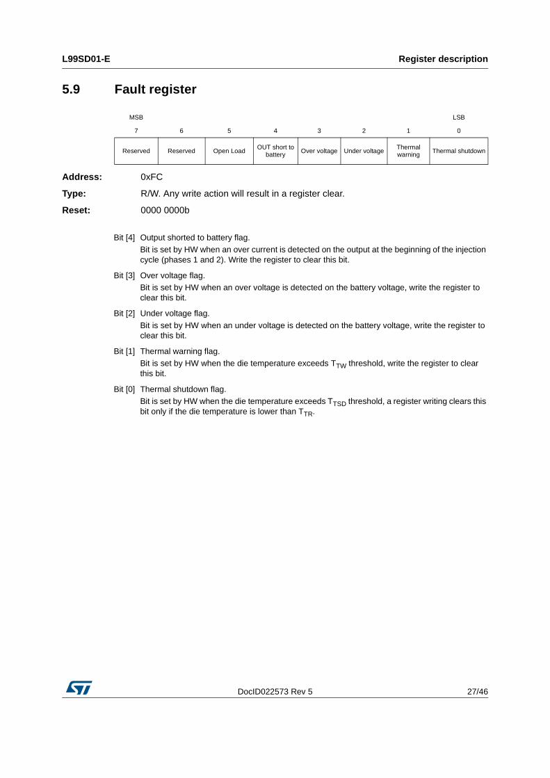
5.9 Fault register
Address: 0xFC
Type: R/W. Any write action will result in a register clear.
Reset: 0000 0000b
MSB LSB
7 6 5 4 3 2 1 0
Reserved Reserved Open LoadOUT short to
battery Over voltage Under voltageThermal warning Thermal shutdown
Bit [4] Output shorted to battery flag. Bit is set by HW when an over current is detected on the output at the beginning of the injection cycle (phases 1 and 2). Write the register to clear this bit.
Bit [3] Over voltage flag. Bit is set by HW when an over voltage is detected on the battery voltage, write the register to clear this bit.
Bit [2] Under voltage flag.
Bit is set by HW when an under voltage is detected on the battery voltage, write the register to clear this bit.
Bit [1] Thermal warning flag.Bit is set by HW when the die temperature exceeds TTW threshold, write the register to clear this bit.
Bit [0] Thermal shutdown flag.Bit is set by HW when the die temperature exceeds TTSD threshold, a register writing clears this bit only if the die temperature is lower than TTR.

Electrical specification L99SD01-E
28/46 DocID022573 Rev 5
6 Electrical specification
6.1 Absolute maximum rating
Table 5. Absolute maximum rating
Symbol Parameter Value Unit
VBATT Maximum DC supply voltage 40 V
VBATT_REV Reverse DC supply voltage -0.3 V
VLOAD Maximum DC load voltage Internally limited V
ILOAD Maximum DC load currentInternally limited
to ISHORTA
IR(LOAD)Maximum reverse output current, TC = 25°C; t = 5 ms.
-20 A
EAS
Single pulse energy S1 switch; VBATT = 13.5 V; Tj = 150°C; L = 6 mH; RL = 0 Ω, typical clamp voltage
88 mJ
EREP1
Repetitive energy S1 switch. VBATT = 13.5 V; Tj = 125°C; L = 6 mH; RL = 0 Ω, typical clamp voltage
38.6 mJ
EREP2
Repetitive energy S1 switch. VBATT = 13.5 V; Tj = -40°C; L = 6 mH; RL = 0 Ω, typical clamp voltage
70 mJ
VC3V3 3.3 V logic supply voltage range -0.3 to 3.6 V
VVDDL 5 V external supply voltage 5.5 V
VSYNC_INJ VE0 VE1 VE2
VCHECK_SIGNALVSCL
VSDA VMAINT_IPKVPWM
VCLAMP_FLAG VFAULT VENABLE
Logic input / output voltage range -0.3 to VDDL+0.3 V
VIN_SIGNAL VREC
HV signal pins -0.3 to VBATT V
VOUT Output pin 55 V
VCTANK Maximum charge pump output voltage VBATT + 15V V
VCPUMP1VCPUMP2
Maximum charge pump pins voltage VBATT V
VESDElectrostatic discharge (R = 1.5kW, C = 100pF, all pins)
+/-2000 V
Tj Junction operating temperature -40 to 150 °C
TSTG Storage temperature -55 to 150 °C
DocID022573 Rev 5 29/46
L99SD01-E Electrical specification
45
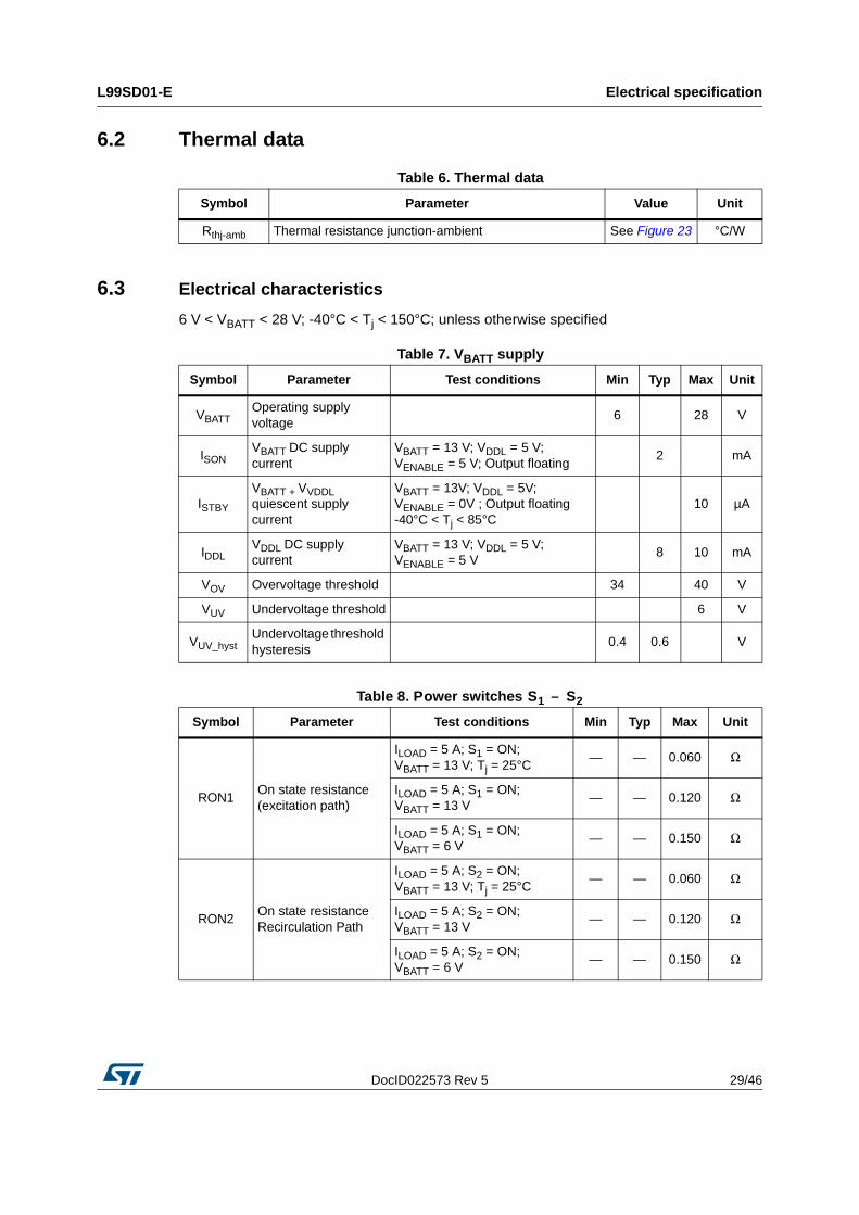
6.2 Thermal data
6.3 Electrical characteristics
6 V < VBATT < 28 V; -40°C < Tj < 150°C; unless otherwise specified
Table 6. Thermal data
Symbol Parameter Value Unit
Rthj-amb Thermal resistance junction-ambient See Figure 23 °C/W
Table 7. VBATT supply
Symbol Parameter Test conditions Min Typ Max Unit
VBATTOperating supply voltage
6 28 V
ISONVBATT DC supply current
VBATT = 13 V; VDDL = 5 V; VENABLE = 5 V; Output floating
2 mA
ISTBY
VBATT + VVDDL quiescent supply current
VBATT = 13V; VDDL = 5V; VENABLE = 0V ; Output floating -40°C < Tj < 85°C
10 µA
IDDLVDDL DC supply current
VBATT = 13 V; VDDL = 5 V; VENABLE = 5 V
8 10 mA
VOV Overvoltage threshold 34 40 V
VUV Undervoltage threshold 6 V
VUV_hystUndervoltage threshold hysteresis
0.4 0.6 V
Table 8. Power switches S1 – S2
Symbol Parameter Test conditions Min Typ Max Unit
RON1On state resistance (excitation path)
ILOAD = 5 A; S1 = ON; VBATT = 13 V; Tj = 25°C
— — 0.060 Ω
ILOAD = 5 A; S1 = ON; VBATT = 13 V
— — 0.120 Ω
ILOAD = 5 A; S1 = ON; VBATT = 6 V
— — 0.150 Ω
RON2On state resistance Recirculation Path
ILOAD = 5 A; S2 = ON; VBATT = 13 V; Tj = 25°C
— — 0.060 Ω
ILOAD = 5 A; S2 = ON; VBATT = 13 V
— — 0.120 Ω
ILOAD = 5 A; S2 = ON; VBATT = 6 V
— — 0.150 Ω

Electrical specification L99SD01-E
30/46 DocID022573 Rev 5
Table 9. S1 switching (excitation path)
Symbol Parameter Test conditions Min Typ Max Unit
TDON_S1 Turn-on delay time
VBATT = 13.5 V; RLOAD = 2.5 Ω
100 180 300 ns
TR_S1Rise time of output voltage
500 900 ns
TDOFF_S1 Turn-off delay time 600 1400 2000 ns
TF_S1Fall time of output voltage
600 1000 ns
VCLAMP_S1Switch S1 clamp voltage
ILOAD = 0.5/14 A; S1 = off; S2 = off
44 55 V
Table 10. Switching (recirculating path)
Symbol Parameter Test conditions Min Typ Max Unit
TDON_S2 Turn-on delay time
VBATT = 13.5 V; RLOAD = 2.5Ω
— 280 600 ns
TR_S2Rise time of output voltage
— 1500 3000 ns
TDOFF_S2 Turn-off delay time — 150 600 ns
TF_S2Fall time of output voltage
— 200 800 ns
Table 11. VDDL undervoltage detection
Symbol Parameter Test conditions Min Typ Max Unit
VPOR_OFFpower-on-reset threshold
VDDL increasing 3.8 4 4.2 V
VPOR_ONpower-on-reset threshold
VDDL decreasing 3.2 3.4 3.6 V
VPOR_hystpower-on-reset hysteresis
VPOR_OFF - VPOR_ON 0.3 V
Table 12. Enable
Symbol Parameter Test conditions Min Typ Max Unit
VENABLE H Enable voltage threshold VBATT = 13 V 1 1.8 2.3 V
VENABLE_L Enable voltage reset VBATT = 13 V 0.8 1.5 1.9 V
VENABLE_HYST Enable voltage hysteresis VBATT = 13 V 0.1 0.3 V
IENABLE Enable pull down current VENABLE = 5 V 20 50 100 µA

DocID022573 Rev 5 31/46
L99SD01-E Electrical specification
45
Table 13. Input: SYNC_INJ
Symbol Parameter Test conditions Min Typ Max Unit
VSYNC_L Input low level voltage VDDL = 5 V 1.08 V
VSYNC_H Input high level voltage VDDL = 5 V 2.1 V
VSYNC_HYST Input hysteresis voltage VDDL = 5 V 0.15 V
ISYNC_INJpull down current at SYNC_INJ input
VSYNC_INJ = 1.5 V 20 50 80 µA
Table 14. Input: PWM
Symbol Parameter Test conditions Min Typ Max Unit
VPWM_L Input low level voltage VDDL = 5 V 1.08 V
VPWM_H Input high level voltage VDDL = 5 V 2.1 V
VPWM_HYST Input hysteresis voltage VDDL = 5 V 0.15 V
IPWMPull down current at PWM input
VPWM = 1.5 V 20 50 80 µA
Table 15. Inputs: E0, E1, E2
Symbol Parameter Test conditions Min Typ Max Unit
VEx_L Input low level voltage VDDL = 5V 1.08 V
VEx_H Input high level voltage VDDL = 5V 2.1 V
VEx_HYST Input hysteresis voltage VDDL = 5V 0.15 V
IEx_IN Pull down current at Ex input VEx = 1.5V 20 50 80 µA
Table 16. IN_SIGNAL VOLTAGE MONITOR, CHECK_SIGNAL
Symbol Parameter Test conditions Min Typ Max Unit
VIN_SIGNAL_LInput low level voltage threshold
0.4 VBATT
0.45 VBATT
0.5 VBATT
V
VIN_SIGNAL_HInput high level voltage threshold
0.5 VBATT
0.55 VBATT
0.6 VBATT
V
VIN_SIGNAL_HYST Input hysteresis voltage0.1
VBATTV
VCHECK_SIGNALCheck_signal output voltage
VIN_SIGNAL = 0 V; ICHECK_SIGNAL = 1 mA
0.9 V
Table 17. Differential current sense amplifier
Symbol Parameter Test conditions Min Typ Max Unit
VICM_AMPInput voltage range – common mode
0 0.8 V

Electrical specification L99SD01-E
32/46 DocID022573 Rev 5
VIDIFF_AMPInput voltage range – differential mode
Gain = 20; VDDL = 5 V 10 80 mV
Gain = 4; VDDL = 5 V 20 400 mV
VIOFF_AMP Input offset voltage VDDL = 5 V -500 500 µV
GainAMP Opamp gainILOAD = IHOLD 20
ILOAD = IPEAK 4
GBWAMPGain bandwidth product
G = 20 2 MHz
G = 4 0.4 MHz
CMRRAMPInput common mode rejection
F = 1 KHz 60 dB
PSRR+AMP3.3 V power supply rejection ratio
55 dB
PSRR-AMPGND power supply rejection ratio
40 dB
TSETTLING_R Rising settling time
G = 20; (VRSP - VRSN) = 0 V to 10 mV in 10 ns
G = 4; (VRSP - VRSN) = 0 V to 20 mV in 10 ns
3.5 µs
TSETTLING_F Falling settling time
G = 20; (VRSP - VRSN) = 10 mV to 0 V in 10 nsG = 4; (VRSP - VRSN) = 20 mV to 0 V in 10 ns
3.5 µs
Table 18. Current sense comparator
Symbol Parameter Test conditions Min Typ Max Unit
VICM_PWMCOMPInput voltage range – common mode
0.05 — 2 V
VIOFF_PWMCOMP Input offset voltage VDDL = 5 V -15 — 6 mV
TDPWMCOMP Input to output delayVINPUT from 200 mV to 1.7 V in 10 ns
— 200 ns
Table 19. 8-bit digital to analog converter
Symbol Parameter Test conditions Min Typ Max Unit
VLSBDAC Less significant bit voltage — 4.851 — mV
Table 17. Differential current sense amplifier (continued)
Symbol Parameter Test conditions Min Typ Max Unit

DocID022573 Rev 5 33/46
L99SD01-E Electrical specification
45
Table 20. S1 protections and diagnostic
Symbol Parameter Test conditions Min Typ Max Unit
TTW
Thermal warning threshold junction temperature
S1 = ON 130 °C
TTSD
Thermal shutdown threshold junction temperature
S1 = ON 155 175 °C
TTR
Thermal reset threshold junction temperature
S1 = ON 130 °C
ISHORTOver current detection
S1 = ON 15 A
IOLOpen-load detection
S1 = ON; IPEAK = 3.2 A
0.2 * (IPEAK/4)
IPEAK/41.2 *
(IPEAK/4)A
S1 = ON; IPEAK = 5 A0.4 *
(IPEAK/4)IPEAK/4
1.2 * (IPEAK/4)
A
S1 = ON; IPEAK ≥ 8 A0.7 *
(IPEAK/4)IPEAK/4
1.3 * (IPEAK/4)
A
VFAULT_OUTStatus output voltage
Diagnostic output active (low); IFAULT = 1 mA
0.9 V
VCLAMPFLAG_OUTClamp diagnostic pin output voltage
ICLAMPFLAG = 100 µA 0.1 V
ICLAMPFLAG = -100µAVDDL -
0.1V
VMAINTIPK_OUT
MAINT_IPK diagnostic pin voltage
IMAINTIPK = 100 µA 0.1 V
IMAINTIPK = -100 µAVDDL -
0.1V
Table 21. Application registers range
Symbol Parameter Test conditions Min Typ Max Unit
IPEAK Register AApplication useful range = 2 → 14 A
0 3.2 20.55 A
IHOLD Register EApplication useful range = 0.5 → 3 A
0 1.7 4.11 A
IHOLD_TEMP Register FApplication useful range = 0.5 → 3.5 A
0 2 4.11 A
tPEAK Register B 0 1.6 5 ms
tHOLD_TEMP Register G 0 0 5 ms
tNO_PEAK_MAX Register H 0 2.5 10 ms
tPEAK_TO_HOLD Register CDEMAG MODE = 0 (slow) 0 10 ms
DEMAG MODE = 1 (fast) 0 70 500 µs

Electrical specification L99SD01-E
34/46 DocID022573 Rev 5
Table 22. IPEAK, IHOLD (-40 °C < Tj < 150 °C, unless otherwise specified)
Symbol Parameter Test conditions(1)
1. VBATT > 8 V
Min Typ Max Unit
IPEAK Peak current
RegisterA = IDEFAULT 2.72 3.2 3.7 A
RegisterA = 2 A 1.60 2 2.40 A
T = 125°C; RegisterA = 2 A 1.70 2 2.30 A
RegisterA = 5 A 4.25 5 5.75 A
RegisterA = 8 A 6.8 8 9.2 A
T = 125°C; RegisterA = 14 A 12.6 14 15.4 A
RegisterA = 14 A 11.9 14 16.1 A
IHOLD Hold current
RegisterE = IDEFAULT 1.445 1.7 1.955 A
T = 125°C; RegisterE = 0.5 A 0.325 0.5 0.6 A
T = 125°C; RegisterE = 1 A 0.9 1 1.1 A
RegisterE = 1 A 0.85 1 1.15 A
RegisterE = 3 A 2.55 3 3.45 A
FPWM PWM frequency Design guaranteed 10 20 KHz
DCYCLE PWM duty cycle FPWM = 20 KHz 0.15
Table 23. Charge pump
Symbol Parameter Test conditions Min Typ Max Unit
VCP Charge pump output voltage(1)
1. Guaranteed by design using suggested external network:CPUMP1, CPUMP2: 4.7 nF - 50 V ceramic capacitors;CTANK: 100 nF - 50 V ceramic capacitor;Charge pump diodes: BAT41 type
ICP = 200 µAVBATT
+ 7VBATT
+ 9VBATT + 13
V
CPUMP1 External charge pump capacitor 4.7 nF
CPUMP2 External charge pump capacitor 4.7 nF
CTANKExternal charge pump capacitor for S2 driver peak current
100 nF
ICP1Charge pump output current positive
VBATT + 7 V < VCTAK< VBATT + 13 V test mode
15 27 34 mA
ICP2Charge pump output current negative
VBATT + 7 V < VCTAK< VBATT + 13 V test mode
-140 -100 -55 mA

DocID022573 Rev 5 35/46
L99SD01-E Electrical specification
45
Table 24. I2C-bus SDA, SCL I/O stages
Symbol Parameter Test conditions Min Typ Max Unit
VILLow level input voltage
—0.3 *
VC3V3V
VIHHigh level input voltage
0.7 * VC3V3
— V
VHYSHysteresis of Schmitt trigger inputs
0.05 * VC3V3
— V
VOLLow level output voltage
ISINK = 3 mA — 0.4 V
IOLLow level output current
VOL = 0.4 V 3 — mA
tOFFOutput fall time from VIHmim to VILmax
— 250 ns
tSP
Pulse width of spikes that must be suppressed by the input filter
— 50 ns
Ii Input current 0.1 * VDDL < VI < 0.9 * VDDL -10 — 10 µA
Ci I/O pin capacitance — 10 pF
Table 25. I2C-bus SDA, SCL bus lines characteristics
Symbol Parameter Test conditions Min Typ Max Unit
All values are referred to VIH(min) (0.3 * VDDL) and VIL(max) (0.7 * VDDL). See also Figure 20.
fSCL SCL clock frequency — 100 kHz
tHD;STAHold time (repeated) START condition
After this period the first clock pulse is generated
4.0 — µs
tLOW LOW period of the SCL clock 4.7 — µs
tHIGHHIGH period of the SCL clock
4.0 — µs
tSU;STASet-up time for a repeated START condition
4.7 — µs
tHD;DAT Data hold time(1) 300(2) — (3) ns
tSU;DAT Data set-up time 250 — ns
trRise time of both SDA and SCL signals
— 1000 ns
tfFall time of both SDA and SCL signals
— 300 ns
tSU;STOSet-up time for a STOP condition
4.0 — µs
tBUFBus free time between a STOP and START condition
4.7 — µs

Electrical specification L99SD01-E
36/46 DocID022573 Rev 5
Figure 20. Definition of timing on the I²C-bus
CbCapacitive load for each bus line
— 400 pF
tVD;DAT Data valid time(4) — 3.45(3) µs
tVD;ACKData valid acknowledge time(5) — 3.45(3) µs
VnLNoise margin at the LOW level
For each connected device (including hysteresis)
0.1 * VDDL
— V
VnHNoise margin at the HIGH level
For each connected device (including hysteresis)
0.2 * VDDL
— V
1. tHD;DAT is the data hold time that is measured from the falling edge of SCL, applies to data in transmission and the acknowledge.
2. A device must internally provide a hold time of at least 300 ns for the SDA signal (with respect to the VIH(min) of the SCL signal) to bridge the undefined region of the falling edge of SCL.
3. The maximum tHD;DAT could be 3.45 us, but must be less than the maximum of tVD;DAT or tVD;ACK by a transition time.
4. tVD;DAT = time for data signal from SCL LOW to SDA output (HIGH or LOW, depending on which one is worse)
5. tVD;ACK = time for acknowledgment signal from SCL LOW to SDA output (HIGH or LOW, depending on which one is worse)
Table 25. I2C-bus SDA, SCL bus lines characteristics
Symbol Parameter Test conditions Min Typ Max Unit

DocID022573 Rev 5 37/46
L99SD01-E Electrical specification
45
Table 26. Electrical transient requirements (part 1)
ISO 7637-2: 2004(E)
Test Pulse
Test levels(1)
1. The above test levels must be considered referred to VCC = 13.5V except for pulse 5b.
Number of pulses or test times
Burst cycle/pulse repetition time
Delays andimpedanceIII IV
1 -75 V -100 V5000
pulses0.5 s 5 s 2 ms, 10 Ω
2a +37 V +50 V5000
pulses0.2 s 5 s 50 μs, 2 Ω
3a -100 V -150 V 1h 90 ms 100 ms 0.1 μs, 50 Ω
3b +75 V +100 V 1h 90 ms 100 ms 0.1 μs, 50 Ω
4 -6 V -7 V 1 pulse 100 ms, 0.01 Ω
5b(2)
2. Valid in case of external load dump clamp: 40V maximum referred to OUT.
+65 V +87 V 1 pulse 400 ms, 2 Ω
Table 27. Electrical transient requirements (part 2)
ISO 7637-2: 2004(E)
test pulse
Test level results(1)
1. The above test levels must be considered referred to VCC = 13.5 V except for pulse 5b.
III IV
1 C E
2a C C
3a C C
3b C C
4 C C
5b (2)
2. Valid in case of external load dump clamp: 40V maximum referred to OUT.
C C
Table 28. Electrical transient requirements (part 3)
Class Contents
C All functions of the device are performed as designed after exposure to disturbance.
EOne or more functions of the device are not performed as designed after exposure to disturbance and cannot be returned to proper operation without replacing the

OTP (One Time Programmable Memory) L99SD01-E
38/46 DocID022573 Rev 5
7 OTP (One Time Programmable Memory)
L99SD01-E provides two 16 bit OTP modules for internal parameter trimming. Default application parameters are hard coded into the device. OTP use is reserved to ST and other access will be hardware forbidden.
Table 29. 16 bit OTP modules
Bit 15
Bit 14
Bit 13
Bit 12
Bit 11
Bit 10
Bit 9
Bit 8
Bit 7
Bit 6
Bit 5
Bit 4
Bit 3
Bit 2
Bit 1
Bit 0
OTP_0 Osc trimming Current reference trimming Bandgap trimming
OTP_1Reference
slopeBlanking IHOLD current trimming

DocID022573 Rev 5 39/46
L99SD01-E Application schematic
45
8 Application schematic
Figure 21. Application schematic
OU
T
REC
REC
REC
REC
PGND
PGND
PGND
PGND
SGND
BATT
CPUMP1
CPUMP2
CTANK
VDDL
C3V3
SGND
E0
E1
E2
SGND
MAINT_IPK
CLAMP_FLAG
CHECK_SIGNAL
IN_SIGNAL
FAULT
ENABLE
SYNC_INJ
PWM
SCL
SDA
Module Battery 4.7nF
4.7nF100nF
xxuF
xxuF
SGND/VDDL
SGND/VDDL
SGND/VDDL
5V
5V 5V 5V
5V
10uF
To mC
Gas Injector
TEST
TEST_OUT3
TEST_OUT2
TEST_OUT1
OTP_15VOTP_0V

Package and PCB thermal data L99SD01-E
40/46 DocID022573 Rev 5
9 Package and PCB thermal data
9.1 PowerSSO-36 thermal data
Figure 22. PowerSSO-36 PC board
1. Board finish thickness 1.6 mm +/- 10%; Board double layer; Board dimension 129 mm x 60 mm; Board Material FR4; Cu thickness 0.070 mm; Thermal vias separation 1.2 mm; Thermal via diameter 0.3 mm +/-0.08 mm; Cu thickness on vias 0.025 mm; Footprint dimension 4.1 mm x 6.5 mm.
GAPGCFT01130

DocID022573 Rev 5 41/46
L99SD01-E Package and PCB thermal data
45
Figure 23. Rthj-amb vs PCB copper area in open box free air condition
Figure 24. PowerSSO-36 thermal impedance junction ambient

Package and PCB thermal data L99SD01-E
42/46 DocID022573 Rev 5
Figure 25. Thermal fitting model of a HSD in PowerSSO-36
Table 30. Thermal parameters
Area/island (cm2) FP 2 8
R1 = R7 (°C/W) 0.8
R2 = R8 (°C/W) 1.2
R3 (°C/W) 5
R4 (°C/W) 8
R5 (°C/W) 18 15 10
R6 (°C/W) 27 23 14
C1 = C7 (W·s/°C) 0.0005
C2 = C8 (W·s/°C) 0.002
C3 (W·s/°C) 0.03
C4 (W·s/°C) 0.5
C5 (W·s/°C) 1 1.5 3
C6 (W·s/°C) 3 5 9

DocID022573 Rev 5 43/46
L99SD01-E Package and packing Information
45
10 Package and packing Information
10.1 ECOPACK® packagesIn order to meet environmental requirements, ST offers these devices in different grades of ECOPACK® packages, depending on their level of environmental compliance. ECOPACK® specifications, grade definitions and product status are available at: www.st.com.
ECOPACK® is an ST trademark.
10.2 PowerSSO-36 package information
Figure 26. PowerSSO-36 package dimensions
AG00066V1
Table 31. PowerSSO-36 mechanical data
SymbolMillimeters
Min Typ. Max
A 2.15 2.47
A2 2.15 2.40
a1 0 0.1
b 0.18 0.36

Package and packing Information L99SD01-E
44/46 DocID022573 Rev 5
c 0.23 0.32
D(1) 10.10 10.50
E 7.4 7.6
e 0.5
e3 8.5
F 2.3
G 0.1
G1 0.06
H 10.1 10.5
h 0.4
k 0° 8°
L 0.55 0.90
M 4.3
N 10°
O 1.2
Q 0.8
S 2.9
T 3.65
U 1
X 4.1 4.7
Y 6.5 7.1
1. “D” and “E“ do not include mold Flash or protrusions. Mold Flash or protrusion shall not exceed 0.15 mm per side (0.006”).
Table 31. PowerSSO-36 mechanical data
SymbolMillimeters
Min Typ. Max
DocID022573 Rev 5 45/46
L99SD01-E Revision history
45
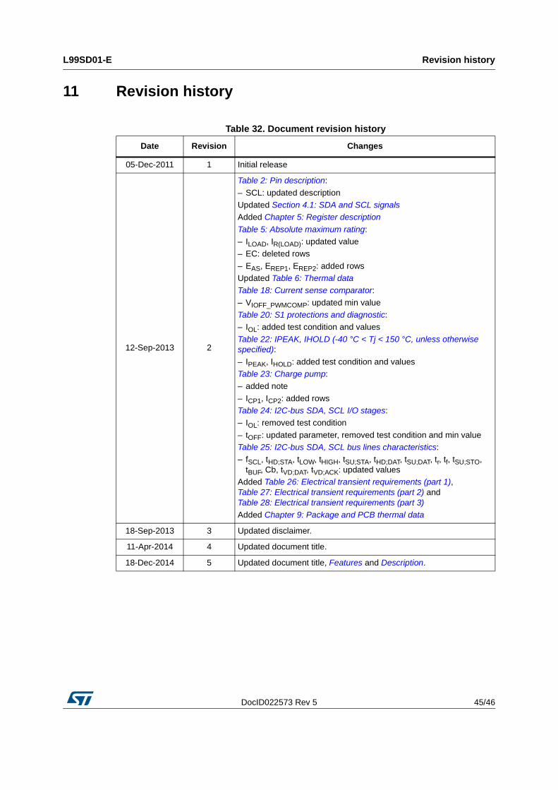
11 Revision history
Table 32. Document revision history
Date Revision Changes
05-Dec-2011 1 Initial release
12-Sep-2013 2
Table 2: Pin description:
– SCL: updated descriptionUpdated Section 4.1: SDA and SCL signalsAdded Chapter 5: Register description
Table 5: Absolute maximum rating:– ILOAD, IR(LOAD): updated value– EC: deleted rows
– EAS, EREP1, EREP2: added rowsUpdated Table 6: Thermal dataTable 18: Current sense comparator:
– VIOFF_PWMCOMP: updated min valueTable 20: S1 protections and diagnostic:– IOL: added test condition and values
Table 22: IPEAK, IHOLD (-40 °C < Tj < 150 °C, unless otherwise specified):
– IPEAK, IHOLD: added test condition and valuesTable 23: Charge pump:– added note
– ICP1, ICP2: added rowsTable 24: I2C-bus SDA, SCL I/O stages:– IOL: removed test condition
– tOFF: updated parameter, removed test condition and min valueTable 25: I2C-bus SDA, SCL bus lines characteristics:– fSCL, tHD;STA, tLOW, tHIGH, tSU;STA, tHD;DAT, tSU;DAT, tr, tf, tSU;STO,
tBUF, Cb, tVD;DAT, tVD;ACK: updated valuesAdded Table 26: Electrical transient requirements (part 1), Table 27: Electrical transient requirements (part 2) and Table 28: Electrical transient requirements (part 3)Added Chapter 9: Package and PCB thermal data
18-Sep-2013 3 Updated disclaimer.
11-Apr-2014 4 Updated document title.
18-Dec-2014 5 Updated document title, Features and Description.

L99SD01-E
46/46 DocID022573 Rev 5
IMPORTANT NOTICE – PLEASE READ CAREFULLY
STMicroelectronics NV and its subsidiaries (“ST”) reserve the right to make changes, corrections, enhancements, modifications, and improvements to ST products and/or to this document at any time without notice. Purchasers should obtain the latest relevant information on ST products before placing orders. ST products are sold pursuant to ST’s terms and conditions of sale in place at the time of order acknowledgement.
Purchasers are solely responsible for the choice, selection, and use of ST products and ST assumes no liability for application assistance or the design of Purchasers’ products.
No license, express or implied, to any intellectual property right is granted by ST herein.
Resale of ST products with provisions different from the information set forth herein shall void any warranty granted by ST for such product.
ST and the ST logo are trademarks of ST. All other product or service names are the property of their respective owners.
Information in this document supersedes and replaces information previously supplied in any prior versions of this document.
© 2014 STMicroelectronics – All rights reserved


![Demagnetization Treatment of Remanent Composite ... · Demagnetization procedures are well-known when it comes to bulk objects such as electromotors and magnetic data carriers [15].](https://static.fdocuments.us/doc/165x107/5e7fe54aa90270489a226c44/demagnetization-treatment-of-remanent-composite-demagnetization-procedures-are.jpg)