Integrated Radiocommunication System (IRCS)€¦ · · 2012-12-14VSAT Very Small Aperture...
19
STANDARD FOR CERTIFICATION DET NORSKE VERITAS AS The content of this service document is the subject of intellectual property rights reserved by Det Norske Veritas AS (DNV). The user accepts that it is prohibited by anyone else but DNV and/or its licensees to offer and/or perform classification, certification and/or verification services, including the issuance of certificates and/or declarations of conformity, wholly or partly, on the basis of and/or pursuant to this document whether free of charge or chargeable, without DNV's prior written consent. DNV is not responsible for the consequences arising from any use of this document by others. The electronic pdf version of this document found through http://www.dnv.com is the officially binding version No. 2.9 Approval Programmes Type Approval Programmes No. 841.10 Integrated Radiocommunication System (IRCS) NOVEMBER 2012
Transcript of Integrated Radiocommunication System (IRCS)€¦ · · 2012-12-14VSAT Very Small Aperture...

STANDARD FOR CERTIFICATION
The content of thaccepts that it is verification servipursuant to this dconsequences aris
The electronic
No. 2.9 Approval Programmes
Type Approval ProgrammesNo. 841.10
Integrated Radiocommunication System (IRCS)
NOVEMBER 2012
DET NORSKE VERITAS AS
is service document is the subject of intellectual property rights reserved by Det Norske Veritas AS (DNV). The userprohibited by anyone else but DNV and/or its licensees to offer and/or perform classification, certification and/orces, including the issuance of certificates and/or declarations of conformity, wholly or partly, on the basis of and/orocument whether free of charge or chargeable, without DNV's prior written consent. DNV is not responsible for theing from any use of this document by others.
pdf version of this document found through http://www.dnv.com is the officially binding version
FOREWORD
DNV is a global provider of knowledge for managing risk. Today, safe and responsible business conduct is both a licenseto operate and a competitive advantage. Our core competence is to identify, assess, and advise on risk management. Fromour leading position in certification, classification, verification, and training, we develop and apply standards and bestpractices. This helps our customers safely and responsibly improve their business performance. DNV is an independentorganisation with dedicated risk professionals in more than 100 countries, with the purpose of safeguarding life, propertyand the environment.
Standards for CertificationStandards for Certification (previously Certification Notes) are publications that contain principles, acceptance criteriaand practical information related to the Society's consideration of objects, personnel, organisations, services and opera-tions. Standards for Certification also apply as the basis for the issue of certificates and/or declarations that may not nec-essarily be related to classification.
© Det Norske Veritas AS November 2012
Any comments may be sent by e-mail to [email protected]
This service document has been prepared based on available knowledge, technology and/or information at the time of issuance of this document, and is believed to reflect the best ofcontemporary technology. The use of this document by others than DNV is at the user's sole risk. DNV does not accept any liability or responsibility for loss or damages resulting fromany use of this document.
Standard for Certification - No. 2.9, November 2012Type Approval Programmes No. 841.10
Changes – Page 3
CHANGES
GeneralThis is a new document.
DET NORSKE VERITAS AS
Standard for Certification - No. 2.9, November 2012Type Approval Programmes No. 841.10
Contents – Page 4
CONTENTS
1. Scope........................................................................................................................................................ 51.1 Abbreviations ...........................................................................................................................................52. Conformity Assessment of Design of Product Type ........................................................................... 62.1 Procedure ..................................................................................................................................................62.2 Documents to be submitted for the IRCS .................................................................................................62.3 Design requirements for IRCS..................................................................................................................72.4 Requirements for identification of product with certificate......................................................................82.5 Elements of type approval ........................................................................................................................83. Table of Type Tests for IRCS ............................................................................................................ 10Appendix A.Applicability of Referenced Publications..................................................................................................... 15
Appendix B.Applicability of Referenced DNV Rules....................................................................................................... 19
DET NORSKE VERITAS AS

Standard for Certification - No. 2.9, November 2012Type Approval Programmes No. 841.10
Sec.1 Scope – Page 5
1 ScopeThe type approval programme is for certifying that the equipment under test conforms to a predetermined setof standards.
The requirements are based on relevant IMO performance standards and IEC test standards as amended.Underlying standards may be used when referred to in “main” standard.
The procedure for assessment of conformity of manufactured products (production) is part of the scope for thetype approval programme.
This type approval programme provides the requirements on which Det Norske Veritas bases its type approvalof Integrated Radio Communication System (IRCS) as defined by IMO resolution A.811(19).
Type approval based on design is a service aimed at manufacturers/designers of IRCS who design and assemblean integrated system of GMDSS radio systems (e.g. VHF, MF/HF, Inmarsat-C and NAVTEX) which havealready been type approved individually according to their relevant performance standards. The IRCS may alsoinclude non-GMDSS communication system (e.g. VSAT) and be integrated with navigational equipment (e.g.AIS or INS), as long as relevant functional and interface requirements are complied with and covered by thetest program.
The key purpose of IRCS is to improve efficiency and ease-of-use for navigators and radio operators. The mainscope of the IRCS Type Approval Program is:
— User interface integration (shared Multi-Functional Displays) — Networking aspects (components, interfaces)— Retention/integrity of key GMDSS functions
The IRCS system may be type approved based on design assessment and a performance test program. Thedesign assessment comprises the following:
— the manufacturer’s design/engineering of the total IRCS— the functional performance of the IRCS in relation to its field of application— the manufacturers own production quality procedures
The design assessment is followed by a performance test program, which at successful completion will lead toa Type Approval Certificate for the IRCS as a system. Note that the Type Approval is only fully valid whenaccompanied by the type approval certificates for the individual components/sub-systems constituting theIRCS. It is important that the IRCS manufacturers ensures that their implementation does not introduce changeswhich may invalidate the type approvals for any of the individual sub-systems in the integrated system.
It is recommended that the IRCS system is type approved in its most complex configuration (incl. all thepossible radio subsystems and interfaces), because then the type approval will also cover subsets of the IRCSsystem (e.g. with fewer radio subsystems/interfaces) as long as constraints and limitations stated in the TypeApproval certificate and the SOLAS IV carriage requirements are adhered to.
For the IRCS components/sub systems which have already undergone environmental laboratory testingaccording to IEC 60945 as part of their individual type approvals, new environmental laboratory testing wouldnormally not need to be repeated for IRCS. However, DNV will during design assessment consider whetherthe IRCS implementation may have introduced changes affecting EMC or environmental characteristics (e.g.temperature, vibration) and may in such cases require new tests towards IEC 60945 to be carried out as part ofthe IRCS type approval program. Any additional components/sub-systems which have not been previouslytested to IEC 60945, are subject to environmental laboratory testing as part of the IRCS program.
1.1 Abbreviations
IRCS Integrated Radiocommunication SystemGMDSS Global Maritime Distress and Safety System INS Integrated Navigational Systems AIS Automatic Identification SystemVSAT Very Small Aperture TerminalWS Work StationFMEA Failure Modes and Effects AnalysisHMI Human-Machine InterfaceMFD Multi-Function Displays.
DET NORSKE VERITAS AS
Standard for Certification - No. 2.9, November 2012Type Approval Programmes No. 841.10
Sec.2 Conformity Assessment of Design of Product Type – Page 6
2 Conformity Assessment of Design of Product Type
2.1 ProcedureType approval procedure consists of the following elements:
— application for type approval of the product— design assessment— type testing— certificate retention survey.
2.2 Documents to be submitted for the IRCSThe following documentation is to be submitted (by email, CD or memory stick) using a common electronicformat and protocol (e.g. Acrobat (pdf) or MS Word format (doc or docx) or AutoCad):
1) A list of the radiocommunication systems (and other systems if applicable) which are intended to beincluded in the integrated system, including copies of valid TA/MED certificates for the relevantperformance standards. Ref. SOLAS IV/14.
Note:The above-mentioned TA/MED certificates should cover the applicable /type/model and the applicable equipmentconfiguration (including network elements) to be used in the integrated system.
---e-n-d---of---N-o-t-e---
2) A block diagram showing the network topology, inter-relationship between all sub-systems, displays,network components, control units, computers, interface ports, power supplies and other parts as relevantfor the IRCS type approval.
Note:The emphasis should be on components and equipment outside / between the integrated sub-systems. As the differentsub-systems have already been type approved, their internal design and components are not of interest in IRCS context(unless such internal parts are shared /interfaced by other parts of the IRCS).
---e-n-d---of---N-o-t-e---
3) Drawings, schematics and functional descriptions necessary to describe the functionality of all parts of theequipment including optional applications.
4) Description of physical/electrical and logical interfaces including data protocol, converters and relevant I/O configuration.
5) Information on: built-in test facilities, failure detection facilities (automatic and manual), data security,monitoring measures, maintenance and periodical testing.
6) A list of all main software modules installed comprising function, name and version number.
7) Drawings and/or pictures showing the user interface of visual display units and user input devices.
8) Description of power supply, including details on transformers, rectifiers, monitoring, capacity,consumption, etc.
Note:Similar to the note under 2), the emphasis should be on components and equipment outside / between the integratedsub-systems. Therefore this documentation is not expected to go into detail of power supply related equipment whichcan be considered integral parts of an underlying radio subsystem and referenced on the corresponding type approvalcertificate.
---e-n-d---of---N-o-t-e---
9) Performance test program.
Note:The performance test program is expected to contain information about test setup /configuration, test procedure andcriteria for verification as well as pass/fail conclusion.
---e-n-d---of---N-o-t-e---
10) Performance type test reports.
11) FMEA, fault tree analysis or similar methods documenting the fail-to-safe principle applied.
12) Specification of operational limitations if any.
13) Operation and installation manuals including on board commissioning specification.
DET NORSKE VERITAS AS
Standard for Certification - No. 2.9, November 2012Type Approval Programmes No. 841.10
Sec.2 Conformity Assessment of Design of Product Type – Page 7
14) Proposed (or required) maintenance procedures.
15) Documentation about the production quality assurance system (e.g. ISO9000).
16) Product marking.
Note:All the documentation submitted shall be marked in accordance with the manufacturer’s QA-system and is to beprepared for easy reference of the various elements asked for.
---e-n-d---of---N-o-t-e---
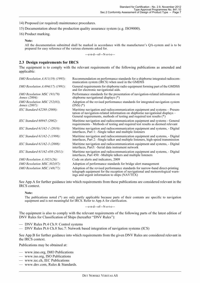
2.3 Design requirements for IRCSThe equipment is to comply with the relevant requirements of the following publications as amended andapplicable:
See App.A for further guidance into which requirements from these publications are considered relevant in theIRCS context.
Note:The publications noted (*) are only partly applicable because parts of their contents are specific to navigationequipment and is not meaningful for IRCS. Refer to App.A for clarification.
---e-n-d---of---N-o-t-e---
The equipment is also to comply with the relevant requirements of the following parts of the latest edition ofDNV Rules for Classification of Ships (hereafter “DNV Rules”):
— DNV Rules Pt.4 Ch.9: Control systems— DNV Rules Pt.6 Ch.8 Sec.7: Network based integration of navigation systems (ICS)
See App.B for further guidance into which requirements from the given DNV Rules are considered relevant inthe IRCS context.
Publications may be obtained at:
— www.imo.org, IMO Publications — www.iso.org, ISO Publications — www.iec.ch, IEC Publications— www.dnv.com, Rules & Standards.
IMO Resolution A.811(19) (1995): Recommendation on performance standards for a shipborne integrated radiocom-munication system (IRCS) when used in the GMDSS
IMO Resolution A.694(17) (1991): General requirements for shipborne radio equipment forming part of the GMDSS and for electronic navigational aids.
IMO Resolution MSC 191(79) Annex (2004):
Performance standards for the presentation of navigation-related information on shipborne navigational displays (*)
IMO Resolution MSC 252(83), Annex (2007):
Adoption of the revised performance standards for integrated navigation system (INS) (*)
IEC Standard 62288 (2008): Maritime navigation and radiocommunication equipment and systems – Presen-tation of navigation-related information on shipborne navigational displays – General requirements, methods of testing and required test results (*)
IEC Standard 60945 (2002): Maritime navigation and radiocommunication equipment and systems - General requirements - Methods of testing and required test results as deemed relevant
IEC Standard 61162-1 (2010): Maritime navigation and radiocommunication equipment and systems, - Digital interfaces, Part 1: -Single talker and multiple listeners
IEC Standard 61162-2 (1998): Maritime navigation and radiocommunication equipment and systems, - Digital interfaces, Part 2: -Single talker and multiple listeners, high-speed transmission
IEC Standard 61162-3 (2008): Maritime navigation and radiocommunication equipment and systems, - Digital interfaces, Part3: -Serial data instrument network
IEC Standard 61162-450 (2011): Maritime navigation and radiocommunication equipment and systems, - Digital interfaces, Part 450: -Multiple talkers and multiple listeners
IMO Resolution A.1021(26): Code on alerts and indicators, 2009IMO Resolution MSC.302(87): Adoption of performance standards for bridge alert managementIMO Resolution MSC.148(77): Adoption of the revised performance standards for narrow-band direct-printing
telegraph equipment for the reception of navigational and meteorological warn-ings and urgent information to ships (NAVTEX)
DET NORSKE VERITAS AS
Standard for Certification - No. 2.9, November 2012Type Approval Programmes No. 841.10
Sec.2 Conformity Assessment of Design of Product Type – Page 8
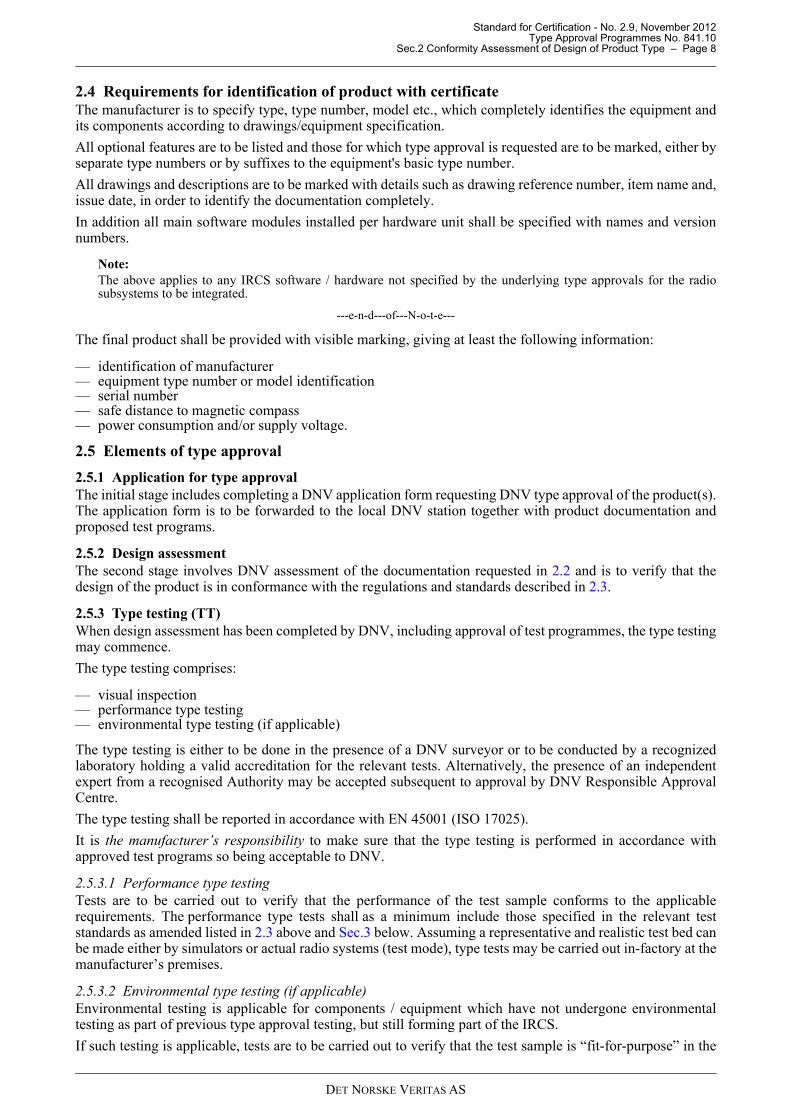
2.4 Requirements for identification of product with certificateThe manufacturer is to specify type, type number, model etc., which completely identifies the equipment andits components according to drawings/equipment specification.
All optional features are to be listed and those for which type approval is requested are to be marked, either byseparate type numbers or by suffixes to the equipment's basic type number.
All drawings and descriptions are to be marked with details such as drawing reference number, item name and,issue date, in order to identify the documentation completely.
In addition all main software modules installed per hardware unit shall be specified with names and versionnumbers.
Note:The above applies to any IRCS software / hardware not specified by the underlying type approvals for the radiosubsystems to be integrated.
---e-n-d---of---N-o-t-e---
The final product shall be provided with visible marking, giving at least the following information:
— identification of manufacturer— equipment type number or model identification— serial number— safe distance to magnetic compass— power consumption and/or supply voltage.
2.5 Elements of type approval
2.5.1 Application for type approvalThe initial stage includes completing a DNV application form requesting DNV type approval of the product(s).The application form is to be forwarded to the local DNV station together with product documentation andproposed test programs.
2.5.2 Design assessmentThe second stage involves DNV assessment of the documentation requested in 2.2 and is to verify that thedesign of the product is in conformance with the regulations and standards described in 2.3.
2.5.3 Type testing (TT)When design assessment has been completed by DNV, including approval of test programmes, the type testingmay commence.
The type testing comprises:
— visual inspection— performance type testing— environmental type testing (if applicable)
The type testing is either to be done in the presence of a DNV surveyor or to be conducted by a recognizedlaboratory holding a valid accreditation for the relevant tests. Alternatively, the presence of an independentexpert from a recognised Authority may be accepted subsequent to approval by DNV Responsible ApprovalCentre.
The type testing shall be reported in accordance with EN 45001 (ISO 17025).
It is the manufacturer’s responsibility to make sure that the type testing is performed in accordance withapproved test programs so being acceptable to DNV.
2.5.3.1 Performance type testingTests are to be carried out to verify that the performance of the test sample conforms to the applicablerequirements. The performance type tests shall as a minimum include those specified in the relevant teststandards as amended listed in 2.3 above and Sec.3 below. Assuming a representative and realistic test bed canbe made either by simulators or actual radio systems (test mode), type tests may be carried out in-factory at themanufacturer’s premises.
2.5.3.2 Environmental type testing (if applicable) Environmental testing is applicable for components / equipment which have not undergone environmentaltesting as part of previous type approval testing, but still forming part of the IRCS.
If such testing is applicable, tests are to be carried out to verify that the test sample is “fit-for-purpose” in the
DET NORSKE VERITAS AS
Standard for Certification - No. 2.9, November 2012Type Approval Programmes No. 841.10
Sec.2 Conformity Assessment of Design of Product Type – Page 9
marine environment as required by IMO performance standards.
The environmental type testing shall be done in accordance with the requirements of IEC 60945. Theperformance testing to be conducted during relevant environmental tests is to be specified in the test programand sent to DNV for approval.
2.5.3.3 It is the manufacturer’s responsibility to ensure that the environmental type testing is performed at anaccredited laboratory accepted by DNV. A laboratory accepted by DNV with the presence of a qualified DNVsurveyor might be used.
2.5.4 Routine tests (RT)The routine tests, including commissioning tests on board, constitute the final production control and themanufacturers standard RT are to be described in the submitted documentation. These tests are normally to becarried out by the manufacturer or his representative unless otherwise stated in the type approval certificate
2.5.5 Initial type approval surveyAn initial TA survey may have to be carried out to confirm that the manufacturer has a production line andquality control for consistent production of the equipment for which TA is requested.
2.5.6 Type approval certificateWhen the design assessment and type testing have been successfully completed a type approval certificate maybe issued to the manufacturer verifying the conformity of the design of the product.
2.5.7 Certification retention surveyPeriodical certificate retention surveys at least every second year is required to maintain the validity of thecertificate. The objective is to verify that a consistent production quality control system is implemented andthat the product has not been altered with respect to design and functions covered by the type approval.
2.5.8 Renewal of type approval certificateAt least three months before the period of validity expires, the certificate holder should apply to the local DNVstation for renewal of the certificate.
Upon receipt of the request for renewal, DNV will perform a certificate retention survey as stated above.
The periodical certificate retention survey report will constitute the basis for renewal of the type approval andthe issuance of a new certificate.
DET NORSKE VERITAS AS
Standard for Certification - No. 2.9, November 2012Type Approval Programmes No. 841.10
Sec.3 Table of Type Tests for IRCS – Page 10
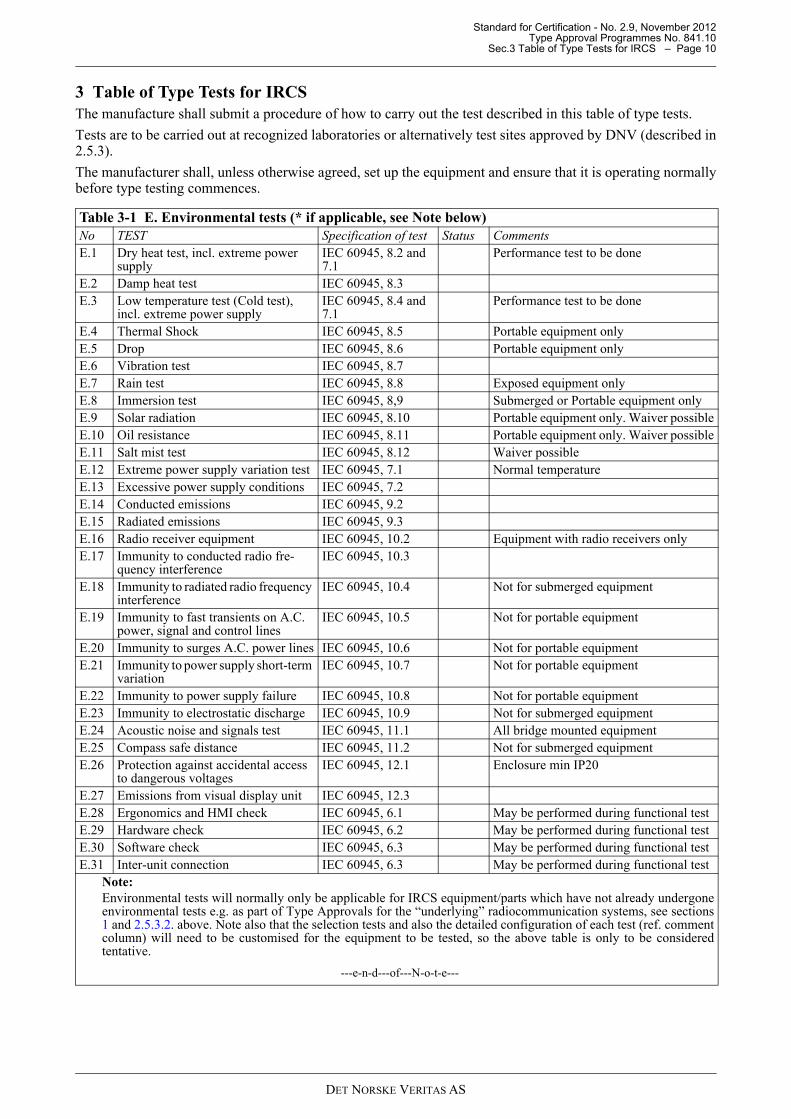
3 Table of Type Tests for IRCS The manufacture shall submit a procedure of how to carry out the test described in this table of type tests.
Tests are to be carried out at recognized laboratories or alternatively test sites approved by DNV (described in2.5.3).
The manufacturer shall, unless otherwise agreed, set up the equipment and ensure that it is operating normallybefore type testing commences.
Table 3-1 E. Environmental tests (* if applicable, see Note below) No TEST Specification of test Status CommentsE.1 Dry heat test, incl. extreme power
supplyIEC 60945, 8.2 and 7.1
Performance test to be done
E.2 Damp heat test IEC 60945, 8.3E.3 Low temperature test (Cold test),
incl. extreme power supplyIEC 60945, 8.4 and 7.1
Performance test to be done
E.4 Thermal Shock IEC 60945, 8.5 Portable equipment onlyE.5 Drop IEC 60945, 8.6 Portable equipment onlyE.6 Vibration test IEC 60945, 8.7E.7 Rain test IEC 60945, 8.8 Exposed equipment onlyE.8 Immersion test IEC 60945, 8,9 Submerged or Portable equipment onlyE.9 Solar radiation IEC 60945, 8.10 Portable equipment only. Waiver possibleE.10 Oil resistance IEC 60945, 8.11 Portable equipment only. Waiver possibleE.11 Salt mist test IEC 60945, 8.12 Waiver possibleE.12 Extreme power supply variation test IEC 60945, 7.1 Normal temperatureE.13 Excessive power supply conditions IEC 60945, 7.2E.14 Conducted emissions IEC 60945, 9.2E.15 Radiated emissions IEC 60945, 9.3E.16 Radio receiver equipment IEC 60945, 10.2 Equipment with radio receivers onlyE.17 Immunity to conducted radio fre-
quency interferenceIEC 60945, 10.3
E.18 Immunity to radiated radio frequency interference
IEC 60945, 10.4 Not for submerged equipment
E.19 Immunity to fast transients on A.C. power, signal and control lines
IEC 60945, 10.5 Not for portable equipment
E.20 Immunity to surges A.C. power lines IEC 60945, 10.6 Not for portable equipmentE.21 Immunity to power supply short-term
variationIEC 60945, 10.7 Not for portable equipment
E.22 Immunity to power supply failure IEC 60945, 10.8 Not for portable equipmentE.23 Immunity to electrostatic discharge IEC 60945, 10.9 Not for submerged equipmentE.24 Acoustic noise and signals test IEC 60945, 11.1 All bridge mounted equipmentE.25 Compass safe distance IEC 60945, 11.2 Not for submerged equipmentE.26 Protection against accidental access
to dangerous voltagesIEC 60945, 12.1 Enclosure min IP20
E.27 Emissions from visual display unit IEC 60945, 12.3E.28 Ergonomics and HMI check IEC 60945, 6.1 May be performed during functional testE.29 Hardware check IEC 60945, 6.2 May be performed during functional testE.30 Software check IEC 60945, 6.3 May be performed during functional testE.31 Inter-unit connection IEC 60945, 6.3 May be performed during functional test
Note:Environmental tests will normally only be applicable for IRCS equipment/parts which have not already undergoneenvironmental tests e.g. as part of Type Approvals for the “underlying” radiocommunication systems, see sections1 and 2.5.3.2. above. Note also that the selection tests and also the detailed configuration of each test (ref. commentcolumn) will need to be customised for the equipment to be tested, so the above table is only to be consideredtentative.
---e-n-d---of---N-o-t-e---
DET NORSKE VERITAS AS
Standard for Certification - No. 2.9, November 2012Type Approval Programmes No. 841.10
Sec.3 Table of Type Tests for IRCS – Page 11
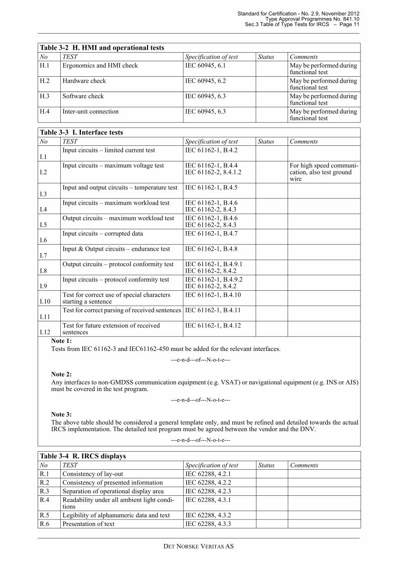
Table 3-2 H. HMI and operational tests No TEST Specification of test Status CommentsH.1 Ergonomics and HMI check IEC 60945, 6.1 May be performed during
functional testH.2 Hardware check IEC 60945, 6.2 May be performed during
functional testH.3 Software check IEC 60945, 6.3 May be performed during
functional testH.4 Inter-unit connection IEC 60945, 6.3 May be performed during
functional test
Table 3-3 I. Interface tests No TEST Specification of test Status Comments
I.1Input circuits – limited current test IEC 61162-1, B.4.2
I.2Input circuits – maximum voltage test IEC 61162-1, B.4.4
IEC 61162-2, 8.4.1.2 For high speed communi-cation, also test ground wire
I.3Input and output circuits – temperature test IEC 61162-1, B.4.5
I.4Input circuits – maximum workload test IEC 61162-1, B.4.6
IEC 61162-2, 8.4.3
I.5Output circuits – maximum workload test IEC 61162-1, B.4.6
IEC 61162-2, 8.4.3
I.6Input circuits – corrupted data IEC 61162-1, B.4.7
I.7Input & Output circuits – endurance test IEC 61162-1, B.4.8
I.8Output circuits – protocol conformity test IEC 61162-1, B.4.9.1
IEC 61162-2, 8.4.2
I.9Input circuits – protocol conformity test IEC 61162-1, B.4.9.2
IEC 61162-2, 8.4.2
I.10Test for correct use of special characters starting a sentence
IEC 61162-1, B.4.10
I.11Test for correct parsing of received sentences IEC 61162-1, B.4.11
I.12Test for future extension of received sentences
IEC 61162-1, B.4.12
Note 1:Tests from IEC 61162-3 and IEC61162-450 must be added for the relevant interfaces.
---e-n-d---of---N-o-t-e---
Note 2:Any interfaces to non-GMDSS communication equipment (e.g. VSAT) or navigational equipment (e.g. INS or AIS)must be covered in the test program.
---e-n-d---of---N-o-t-e---
Note 3:The above table should be considered a general template only, and must be refined and detailed towards the actualIRCS implementation. The detailed test program must be agreed between the vendor and the DNV.
---e-n-d---of---N-o-t-e---
Table 3-4 R. IRCS displays No TEST Specification of test Status CommentsR.1 Consistency of lay-out IEC 62288, 4.2.1R.2 Consistency of presented information IEC 62288, 4.2.2R.3 Separation of operational display area IEC 62288, 4.2.3R.4 Readability under all ambient light condi-
tionsIEC 62288, 4.3.1
R.5 Legibility of alphanumeric data and text IEC 62288, 4.3.2R.6 Presentation of text IEC 62288, 4.3.3
DET NORSKE VERITAS AS
Standard for Certification - No. 2.9, November 2012Type Approval Programmes No. 841.10
Sec.3 Table of Type Tests for IRCS – Page 12
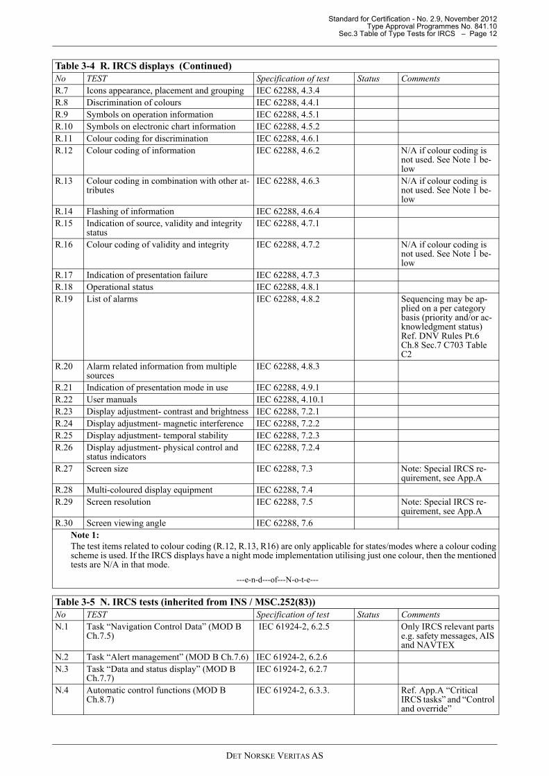
R.7 Icons appearance, placement and grouping IEC 62288, 4.3.4R.8 Discrimination of colours IEC 62288, 4.4.1R.9 Symbols on operation information IEC 62288, 4.5.1R.10 Symbols on electronic chart information IEC 62288, 4.5.2R.11 Colour coding for discrimination IEC 62288, 4.6.1R.12 Colour coding of information IEC 62288, 4.6.2 N/A if colour coding is
not used. See Note 1 be-low
R.13 Colour coding in combination with other at-tributes
IEC 62288, 4.6.3 N/A if colour coding is not used. See Note 1 be-low
R.14 Flashing of information IEC 62288, 4.6.4R.15 Indication of source, validity and integrity
statusIEC 62288, 4.7.1
R.16 Colour coding of validity and integrity IEC 62288, 4.7.2 N/A if colour coding is not used. See Note 1 be-low
R.17 Indication of presentation failure IEC 62288, 4.7.3R.18 Operational status IEC 62288, 4.8.1R.19 List of alarms IEC 62288, 4.8.2 Sequencing may be ap-
plied on a per category basis (priority and/or ac-knowledgment status) Ref. DNV Rules Pt.6 Ch.8 Sec.7 C703 Table C2
R.20 Alarm related information from multiple sources
IEC 62288, 4.8.3
R.21 Indication of presentation mode in use IEC 62288, 4.9.1R.22 User manuals IEC 62288, 4.10.1R.23 Display adjustment- contrast and brightness IEC 62288, 7.2.1R.24 Display adjustment- magnetic interference IEC 62288, 7.2.2R.25 Display adjustment- temporal stability IEC 62288, 7.2.3R.26 Display adjustment- physical control and
status indicatorsIEC 62288, 7.2.4
R.27 Screen size IEC 62288, 7.3 Note: Special IRCS re-quirement, see App.A
R.28 Multi-coloured display equipment IEC 62288, 7.4R.29 Screen resolution IEC 62288, 7.5 Note: Special IRCS re-
quirement, see App.AR.30 Screen viewing angle IEC 62288, 7.6
Note 1:The test items related to colour coding (R.12, R.13, R16) are only applicable for states/modes where a colour codingscheme is used. If the IRCS displays have a night mode implementation utilising just one colour, then the mentionedtests are N/A in that mode.
---e-n-d---of---N-o-t-e---
Table 3-5 N. IRCS tests (inherited from INS / MSC.252(83)) No TEST Specification of test Status CommentsN.1 Task “Navigation Control Data” (MOD B
Ch.7.5) IEC 61924-2, 6.2.5 Only IRCS relevant parts
e.g. safety messages, AIS and NAVTEX
N.2 Task “Alert management” (MOD B Ch.7.6) IEC 61924-2, 6.2.6N.3 Task “Data and status display” (MOD B
Ch.7.7)IEC 61924-2, 6.2.7
N.4 Automatic control functions (MOD B Ch.8.7)
IEC 61924-2, 6.3.3. Ref. App.A “Critical IRCS tasks” and “Control and override”
Table 3-4 R. IRCS displays (Continued)No TEST Specification of test Status Comments
DET NORSKE VERITAS AS
Standard for Certification - No. 2.9, November 2012Type Approval Programmes No. 841.10
Sec.3 Table of Type Tests for IRCS – Page 13
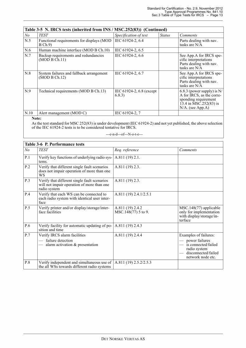
N.5 Functional requirements for displays (MOD B Ch.9)
IEC 61924-2, 6.4 Parts dealing with nav. tasks are N/A
N.6 Human machine interface (MOD B Ch.10) IEC 61924-2, 6.5N.7 Backup requirements and redundancies
(MOD B Ch.11) IEC 61924-2, 6.6 See App.A for IRCS spe-
cific interpretations Parts dealing with nav. tasks are N/A
N.8 System failures and fallback arrangement (MOD B Ch.12)
IEC 61924-2, 6.7 See App.A for IRCS spe-cific interpretations Parts dealing with nav. tasks are N/A
N.9 Technical requirements (MOD B Ch.13) IEC 61924-2, 6.8 (except 6.8.3)
6.8.3 (power supply) is N/A for IRCS, as the corre-sponding requirement 13.4 in MSC.252(83) is N/A. (see App.A)
N.10 Alert management (MOD C) IEC 61924-2, 7Note:As the test standard for MSC 252(83) is under development (IEC 61924-2) and not yet published, the above selectionof the IEC 61924-2 tests is to be considered tentative for IRCS.
---e-n-d---of---N-o-t-e---
Table 3-6 P. Performance tests No TEST Req. reference Comments
P.1 Verify key functions of underlying radio sys-tems.
A.811 (19) 2.1.
P.2 Verify that different single fault scenarios does not impair operation of more than one WS
A.811 (19) 2.3.
P.3 Verify that different single fault scenarios will not impair operation of more than one radio system
A.811 (19) 2.3.
P.4 Verify that each WS can be connected to each radio system with identical user inter-face
A.811 (19) 2.4.1/2.5.1
P.5 Verify printer and/or display/storage/inter-face facilities
A.811 (19) 2.4.2 MSC.148(77) 5 to 9.
MSC.148(77) applicable only for implementation with display/storage/in-terface
P.6 Verify facility for automatic updating of po-sition and time
A.811 (19) 2.4.3
P.7 Verify IRCS alarm facilities — failure detection — alarm activation & presentation
A.811 (19) 2.4.4 Examples of failures: — power failures— is connected/failed
radio system — disconnected/failed
network node etc. P.8 Verify independent and simultaneous use of
the all WSs towards different radio systemsA.811 (19) 2.5.2/2.5.3
Table 3-5 N. IRCS tests (inherited from INS / MSC.252(83)) (Continued)No TEST Specification of test Status Comments
DET NORSKE VERITAS AS
Standard for Certification - No. 2.9, November 2012Type Approval Programmes No. 841.10
Sec.3 Table of Type Tests for IRCS – Page 14
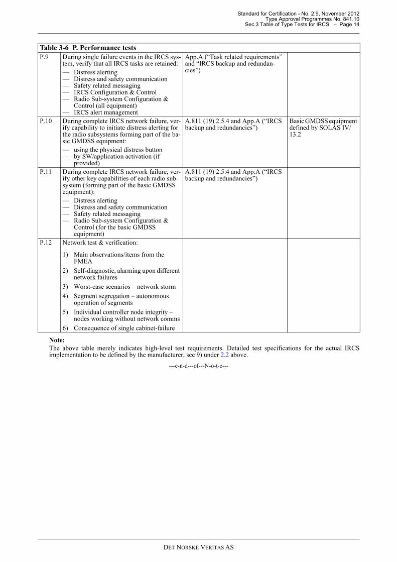
Note:The above table merely indicates high-level test requirements. Detailed test specifications for the actual IRCSimplementation to be defined by the manufacturer, see 9) under 2.2 above.
---e-n-d---of---N-o-t-e---
P.9 During single failure events in the IRCS sys-tem, verify that all IRCS tasks are retained: — Distress alerting— Distress and safety communication— Safety related messaging— IRCS Configuration & Control— Radio Sub-system Configuration &
Control (all equipment) — IRCS alert management
App.A (“Task related requirements” and “IRCS backup and redundan-cies”)
P.10 During complete IRCS network failure, ver-ify capability to initiate distress alerting for the radio subsystems forming part of the ba-sic GMDSS equipment: — using the physical distress button — by SW/application activation (if
provided)
A.811 (19) 2.5.4 and App.A (“IRCS backup and redundancies”)
Basic GMDSS equipment defined by SOLAS IV/13.2
P.11 During complete IRCS network failure, ver-ify other key capabilities of each radio sub-system (forming part of the basic GMDSS equipment): — Distress alerting— Distress and safety communication— Safety related messaging — Radio Sub-system Configuration &
Control (for the basic GMDSS equipment)
A.811 (19) 2.5.4 and App.A (“IRCS backup and redundancies”)
P.12 Network test & verification:
1) Main observations/items from the FMEA
2) Self-diagnostic, alarming upon different network failures
3) Worst-case scenarios – network storm
4) Segment segregation – autonomous operation of segments
5) Individual controller node integrity – nodes working without network comms
6) Consequence of single cabinet-failure
Table 3-6 P. Performance tests
DET NORSKE VERITAS AS
Standard for Certification - No. 2.9, November 2012Type Approval Programmes No. 841.10
Appendix A Applicability of Referenced Publications – Page 15
Appendix AApplicability of Referenced PublicationsThis appendix seeks to provide further guidance into the interpretation and applicability of the publicationsreferenced in 2.3 (Design requirements for IRCS) above.
A.1 IMO Resolution A.811(19)As this publication defines IMO’s adopted recommendation on performance standards for a shipborne IRCSwhen used in GMDSS, the whole content is relevant and applicable. However, the following sections aresubject to clarification and interpretation:
Alternative printing facilities (2.4.2)
IMO Resolution A.811(19) 2.4.2 states that two printers are required, but solutions using IRCS Work stationdisplays accompanied by non-volatile storage for retaining a message log history is accepted as an equivalentsolution. In this case, the requirements contained in sections 5 to 9 of MSC.148(77) (the revised performancestandard for NAVTEX) shall be complied with.
Distress activation facilities (2.5.4)
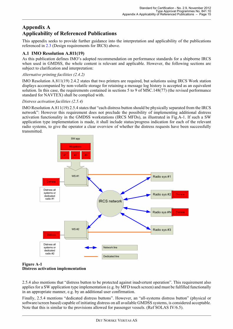
IMO Resolution A.811(19) 2.5.4 states that “each distress button should be physically separated from the IRCSnetwork”: However this requirement does not preclude the possibility of implementing additional distressactivation functionality in the GMDSS workstations (IRCS MFDs), as illustrated in Fig.A-1. If such a SWapplication type implementation is made, it shall include status/progress indication for each of the relevantradio systems, to give the operator a clear overview of whether the distress requests have been successfullytransmitted.
Figure A-1Distress activation implementation
2.5.4 also mentions that “distress button to be protected against inadvertent operation”. This requirement alsoapplies for a SW application type implementation (e.g. by MFD touch screen) and must be fulfilled functionallyin an appropriate manner, e.g. by an additional user confirmation.
Finally, 2.5.4 mentions “dedicated distress buttons”. However, an “all-systems distress button” (physical orsoftware/screen based) capable of initiating distress on all available GMDSS systems, is considered acceptable.Note that this is similar to the provisions allowed for passenger vessels. (Ref SOLAS IV/6.5).
IRCS network
Radio sys #1
Radio sys #N
Radio sys #3
Radio sys #2
WS #1
WS #2
Distress
Distress
Distress
Distress
Distress all systems or dedicated radio #1
Distress all systems or dedicated radio #2
All systems
#1 #3#2
SW app
Network line
Dedicated line
DET NORSKE VERITAS AS
Standard for Certification - No. 2.9, November 2012Type Approval Programmes No. 841.10
Appendix A Applicability of Referenced Publications – Page 16
Local control of key GMDSS capabilities:
Key GMDSS capabilities of the underlying radio subsystems shall be available by local control i.e. independentof the IRCS system. As an example, it must be possible to make distress and safety communication for longand short distances when the IRCS network is down.
IRCS integration with non-GMDSS communications equipment
This is possible provided that no functional or performance requirements of the IRCS system or the underlyingradio subsystems are affected. The performance test program should reflect this by inclusion of relevantverification tests.
IRCS integration with navigational equipment/INS
This is possible provided that no functional or performance requirements of the IRCS system, the underlyingradio subsystems nor the applicable navigational equipment are affected. The performance test program shouldreflect this by inclusion of relevant verification tests. Note also that interfacing requirements defined by INSmust be complied with.
A.2 IMO Resolution MSC 191(79)As this publication is developed for navigational systems all parts are not directly transferable to IRCS,however the general principles presented are applicable. In addition, the following sections are directlyapplicable:
— Paragraph 5 “General requirements for the presentation of information”— Paragraph 8 “Physical requirements”.
Note:The above paragraphs correspond to respective paragraphs 4 and 7 in IEC 622888(2008), ref. Table of Type tests inprevious section of this document.
---e-n-d---of---N-o-t-e---
The following sections of MSC.191(79) are subject to clarification/ interpretation:
8.2 Screen Size
— The IRCS workstations shall comply with requirement 8.2.1.— If the IRCS workstations are used for chart presentation for route monitoring or radar presentation then the
relevant requirements (8.2.2 and/or 8.2.3) shall be fulfilled accordingly
Note:Although no specific minimum screen size requirement is defined for IRCS, there exist requirements elsewhere whichaffect the minimum screen size implicitly e.g. the requirements to readability of text and requirements to size andnumbers of symbols used as shortcuts for critical IRCS tasks Ref. IEC 60945-4 (6.1.2 (for touch screen) and 6.1.4)and IEC 62288 4.5.1.
---e-n-d---of---N-o-t-e---
8.4 Screen Resolution
Considering the screen size requirement for radar presentation on a >500 gt vessel given by 8.2.3 (250 mm ×250 mm) and the pixel based requirements in 8.4 (1280 × 1024), the corresponding resolution can be derivedfrom the width: 1024 pixels / 250 mm = 4.1 pixels/mm.
The resolution requirement for IRCS displays is based on the above and shall be minimum 4.1 pixels/mm.
Example: A 7” widescreen display of 150 mm × 100 mm, must have at least 615 × 410 pixels.
A.3 IMO Resolution MSC 252(83)As this publication is developed for navigation systems all parts are not directly transferable to IRCS, howeverthe general principles presented are applicable. In addition, the following sections are directly applicable:
— Module B 6 “Task related requirement for INS: Operational Requirements”— Module B 9 “Functional requirements for displays of INS” except paragraph 9.2— Module B 10 “Human machine Interface”— Module C “Alert management”.
Note:The contents related to navigation tasks cannot be directly transferred to IRCS, and should be interpreted ascommunication related tasks. Also references to INS should be read as IRCS.
---e-n-d---of---N-o-t-e---
DET NORSKE VERITAS AS

Standard for Certification - No. 2.9, November 2012Type Approval Programmes No. 841.10
Appendix A Applicability of Referenced Publications – Page 17
Task related requirement for IRCS (Module B 7)
Module B 7 “Task related requirement for INS” applies principally, but is subject to the following clarificationsand interpretations. The configuration of the IRCS shall be modular and task-oriented. The following tasks aredefined for IRCS:
— Distress alerting: the capability to perform distress to each of the integrated radio subsystems with suchcapability.
— Distress and safety communication— Voice calls: the capability to initiate and receive two-way voice calls using the integrated radio subsystems
with such capability. — Safety related messaging: sending & reception of safety related messages via NAVTEX and/or Inmarsat-C.— IRCS Configuration & Control: configuration & control of the complete IRCS system — Radio Sub-system Configuration & Control: configuration & control of each radio subsystem integrated in
the IRCS — IRCS alert management (as defined in Module C of MSC.252 (83)).
Critical IRCS tasks (Module B 8.7)
A subset of IRCS tasks are defined as critical and shall comply with the requirements defined under “Automaticcontrol functions” (Module B 8.7). The following IRCS tasks are considered critical and must therefore beavailable to the operator for continuous display and selection, at least upon a single operator command:
— Distress alerting: a distress capability: physical (or software) button to be available at all times — IRCS alert management: implying that important IRCS errors/ alarms shall pop up and alert the user
immediately regardless of which task is executed and which mode the IRCS is in. — IRCS Configuration & Control: the possibility to get an IRCS overview (e.g. showing status IRCS network
components and status of underlying radio systems) shall never be more than a click away. — Radio Sub-system Configuration & Control: shall be possible to activate immediately for each of the radio
systems comprising the basic GMDSS equipment(*) for the Sea Areas the vessel is to operate in.(refSOLAS IV/7-11).
Note:(*): Basic GMDSS equipment is defined as the equipment covered by the SOLAS maintenance requirements, refSOLAS IV/13.2 and IMO Res.702(17) as referred to by SOLAS IV/15.
---e-n-d---of---N-o-t-e---
Control and override (Module B 8.7)
The paragraph “Automatic control functions” (Module B 8.7) also deals with control and override functionalityfrom the work stations. Although automatic control functions such as auto-pilot is not relevant in IRCS context,the same principles shall apply for the relevant IRCS tasks, in order to avoid inconsistent configuration and/orresource conflicts. For example:
— Only one clearly indicated work station shall be in control of a critical IRCS function, and only one workstation shall at any time be assigned to accept control commands (e.g. change channel on VHF, changesatellite/LES on Inmarsat-C etc).
— It shall be clearly indicated to the operator which of the workstations are in control of the particular radiosubsystem, and attempts to enter a similar control command session to the same radio subsystem fromanother work station shall be handled appropriately (e.g. rejected with busy notification or offering acontrolled transfer of the command).
— Any operator attempts causing conflicting use of the resources or services of the underlying radiosubsystems shall be handled by the IRCS system and accompanied with appropriate user notifications. (e.g.attempts to initiate voice calls simultaneously from two work station, when the underlying radio subsystemcan only support one call).
IRCS Back up requirement and redundancies (Module B 11)
Module B 11 “INS Back up requirement and redundancies” applies principally, but is subject to the followingclarifications and interpretations:
— “INS” to be read as “IRCS” and “safe navigation” to be read as “successful communication”— 11.1.4. The failure or loss of one hardware component of the IRCS should not result in the loss of any one
of the IRCS tasks (for definitions of IRCS tasks see above). During complete IRCS failure it shall still bepossible to continue executing the following tasks by bypass or alternative means:
— Distress alerting— Distress and safety communication— Safety related messaging
DET NORSKE VERITAS AS
Standard for Certification - No. 2.9, November 2012Type Approval Programmes No. 841.10
Appendix A Applicability of Referenced Publications – Page 18
— Radio Sub-system Configuration & Control (for the Basic GMDSS systems)
— 11.2. N/A for IRCS.
System failures and fallback arrangement (Module B 12):
Module B 12 “System failures and fallback arrangement” applies principally, but is subject to the followingclarifications and interpretations:
— “INS” to be read as “IRCS”— 12.7. (Fallback for navigational information failure) does not apply to IRCS, but the following
requirements applies for failures to any of the integrated radio subsystems:
— The HMI shall indicate clearly which radio-system has failed, and if possible the nature/cause of thefailure
— The respective actions of the alert management system shall be activated.
Technical requirements (Module B 13):
Module B Chapter 13 “Module B 13 “Technical requirements applies in its entirety, except for 13.4 (powersupplies) which is already covered by SOLAS IV /Reg. 13.
DET NORSKE VERITAS AS
Standard for Certification - No. 2.9, November 2012Type Approval Programmes No. 841.10
Appendix B Applicability of Referenced DNV Rules – Page 19
”
-
” S
,
s--
Appendix BApplicability of Referenced DNV RulesThis appendix seeks to provide further guidance into the interpretation and applicability of the DNV Rulessections referenced in 2.3 (“Design requirements for IRCS”) above.
The latest revision of the DNV Rules shall be used. The rule references provided in the tables below have beenbased on the January 2012 revision.
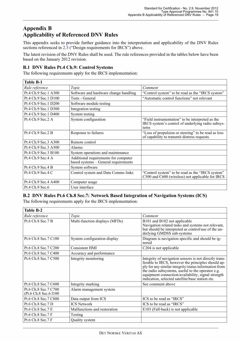
B.1 DNV Rules Pt.4 Ch.9: Control SystemsThe following requirements apply for the IRCS implementation:
B.2 DNV Rules Pt.6 Ch.8 Sec.7: Network Based Integration of Navigation Systems (ICS) The following requirements apply for the IRCS implementation:
Table B-1 Rule reference Topic Comment Pt.4 Ch.9 Sec.1 A300 Software and hardware change handling “Control system” to be read as the “IRCS systemPt.4 Ch.9 Sec.1 D100 Tests - General “Automatic control functions” not relevant Pt.4 Ch.9 Sec.1 D200 Software module testingPt.4 Ch.9 Sec.1 D300 Integration testingPt.4 Ch.9 Sec.1 D400 System testingPt.4 Ch.9 Sec.2 A System configuration “Field instrumentation” to be interpreted as the
IRCS system’s control of underlying radio subsystems
Pt.4 Ch.9 Sec.2 B Response to failures “Loss of propulsion or steering” to be read as lossof capability to transmit distress requests.
Pt.4 Ch.9 Sec.3 A300 Remote controlPt.4 Ch.9 Sec.3 A500 Alarms Pt.4 Ch.9 Sec.3 B100 System operations and maintenancePt.4 Ch.9 Sec.4 A Additional requirements for computer
based systems – General requirementsPt.4 Ch.9 Sec.4 B System software Pt.4 Ch.9 Sec.4 C Control system and Data Comms links “Control system” to be read as the “IRCS system
C500 and C600 (wireless) not applicable for IRCPt.4 Ch.9 Sec.4 A400 Computer usagePt.4 Ch.9 Sec.6 User interface
Table B-2 Rule reference Topic Comment Pt.6 Ch.8 Sec.7 B Multi-function displays (MFDs) B101 and B102 not applicable
Navigation related tasks and systems not relevantbut should be interpreted as control/use of the un-derlying GMDSS sub-systems
Pt.6 Ch.8 Sec.7 C100 System configuration display Diagram is navigation specific and should be ig-nored
Pt.6 Ch.8 Sec.7 C200 Consistent HMI C204 is not applicable Pt.6 Ch.8 Sec.7 C400 Accuracy and performancePt.6 Ch.8 Sec.7 C500 Integrity monitoring Integrity of navigation sensors is not directly tran
ferable to IRCS, however the principles should apply for any similar integrity/status information fromthe radio subsystems, useful to the operator e.g. equipment connection/availability, signal strengthindication, selected satellite/base station etc.
Pt.6 Ch.8 Sec.7 C600 Integrity marking See comment abovePt.6 Ch.8 Sec.7 C700(Pt.6 Ch.8 Sec.6 I100
Alarm management system
Pt.6 Ch.8 Sec.7 C800 Data output from ICS ICS to be read as “IRCS”Pt.6 Ch.8 Sec.7 D ICS Network ICS to be read as “IRCS”Pt.6 Ch.8 Sec.7 E Malfunctions and restoration E103 (Fall-back) is not applicablePt.6 Ch.8 Sec.7 F Testing Pt.6 Ch.8 Sec.7 F Quality system
DET NORSKE VERITAS AS