Good FMEA / Bad FMEA William... · · 2016-06-18Good FMEA / Bad FMEA By: William Mulligan Session...
42
October 22, 2014 ASQ NEQC 60th Conference, Springfield, Massachusetts Good FMEA / Bad FMEA By: William Mulligan Session 23E
-
Upload
duongquynh -
Category
Documents
-
view
231 -
download
0
Transcript of Good FMEA / Bad FMEA William... · · 2016-06-18Good FMEA / Bad FMEA By: William Mulligan Session...

October 22, 2014 ASQ NEQC 60th Conference, Springfield, Massachusetts
Good FMEA / Bad FMEA
By:
William Mulligan
Session 23E

January 28th, 1986
74.201
Seconds76 +
Seconds
October 22, 2014 ASQ NEQC 60th Conference, Springfield, Massachusetts 2

The Overall Purpose of FMEA is to Lower Risk
3
D. H. Stamatis, FMEA:FMEA from Theory
to Practice, Quality Press, 1995
Unclear Customer
Expectations (AFMEA)
Potential Safety
Hazards (ALL)
Insufficient Knowledge of
Environmental Requirements
(ALL)
Poor Design
(DFMEA)
Raw Material
Variation
(PFMEA)
Poorly developed
Specification Limits
(DFMEA / AFMEA)Measurement
Variation (PFMEA)Machine Reliability
(PFMEA)
Poor Process Control
(PFMEA)
Cumulative Risk
Risk can derive from:
October 22, 2014 ASQ NEQC 60th Conference, Springfield, Massachusetts
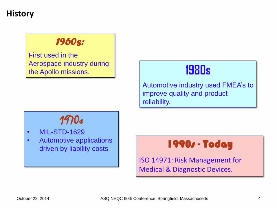
History
1990s - TodayISO 14971: Risk Management for Medical & Diagnostic Devices.
4
1960s:
First used in the
Aerospace industry during
the Apollo missions.
1970s• MIL-STD-1629
• Automotive applications
driven by liability costs
1980sAutomotive industry used FMEA’s to
improve quality and product
reliability.
October 22, 2014 ASQ NEQC 60th Conference, Springfield, Massachusetts

Definition - FMEA
A bottom-up structured approach to:
– Identify the ways in which a product can fail. Specifically, the Root Cause(s) of failure, the Failure Mode(s), and the Effect(s) of failure.
–Estimate the risk associated with each Failure Scenario.
–Rank-order the Failure Scenarios to prioritize the design team’s efforts.
–Track corrective actions and provide a permanent record for subsequent FMEAs.
The FMEA is a living document which is updated throughout the life of the product.
5
Primary Directive: Identify ways that a product can fail and take
action to remove the failure modes before they occur.
October 22, 2014 ASQ NEQC 60th Conference, Springfield, Massachusetts

Types of FMEA
Process (PFMEA): Analyzes errors in manufacturing and assembly
processes:
Focuses on process inputs (what can go wrong in the manufacturing process).
Defective components are a consideration.
Design (DFMEA): Analyzes the product design before release to production:
Assumes that the product is properly manufactured to design specifications.
Focuses on product function – suitability of components, geometry, materials, etc. to
produce the desired function.
Application (AFMEA): Analyzes the suitability of a product to meet the
needs and expectations of the customer:
Anticipated and “off-label” uses are considered as well as shipping, storage, disposal.
Assumes that the product is properly manufactured to design specifications.
October 22, 2014 ASQ NEQC 60th Conference, Springfield, Massachusetts 6

7
Incorrect or
Defective Design
(DFMEA)
Process Defect
(PFMEA)
Product cannot
meet performance
targets –
anitcipated use
Product is difficult
to manufacture
Inappropriate
Design (AFMEA)
Product is
awkward to use or
non-intuitive
Product is
dangerous if
accidentally
misused
Performance
degrades over
time
Unreasonable
tolerances or
material properties
Product appearance or
performance degrades
due to exposure to
unanticipated
environmental
conditions
Unclear instructions
for use, or
inadequate warnings
Product dangerous
if dropped /
impacted / tipped
over etc.
Performance
varies from
product to product
Results in
Which means
Results in
Non-robust
manufacturing
techniques
required
Which means
Results in
Ineffective, Inappropriate, or Incorrect
Design Inputs
Which can lead to
Which can lead to
A process defect
may cause any of
the results above
Contributing factor
Product
appearance or
performance
inadequate during
unanticipated use.
link
Performance
varies under
anticipated
conditions
Results in
Results in
Which means
Functionality
issuesIncorrect assembly
Missing parts or
accessories
Dirt / marks /
particulate matter
Caused by
Inappropriate mfg
environment
Out-of-spec raw
materials or
components
Process not
validated, fixtures
not poka-yoked,
training issues,
design issues
Inadequate
training, design
issues
How all three FMEA types relate to each other
October 22, 2014 ASQ NEQC 60th Conference, Springfield, Massachusetts

FMEA Inputs and Outputs
•Inputs:
Product concept design
QFD
Experience with related products
Benchmarking
Product performance requirements
•Outputs:
Prioritized list of actions to prevent / minimize Root Causes or to detect Failure Modes
History of actions taken
8October 22, 2014 ASQ NEQC 60th Conference, Springfield, Massachusetts
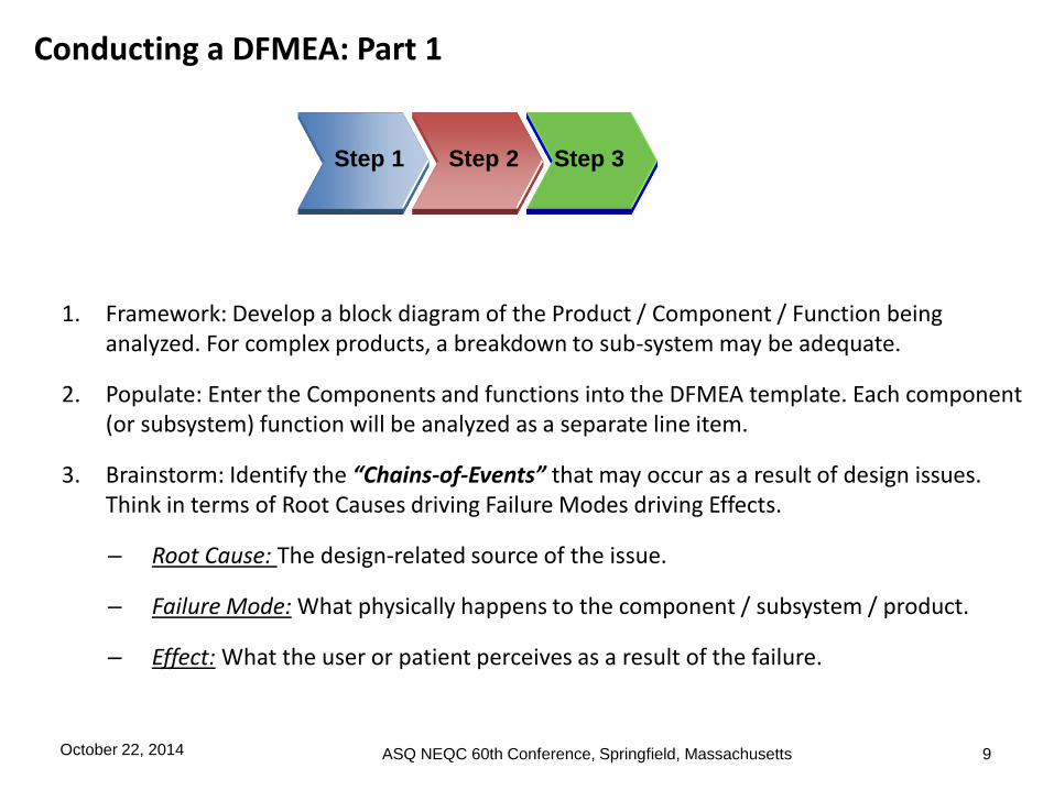
Conducting a DFMEA: Part 1
1. Framework: Develop a block diagram of the Product / Component / Function being analyzed. For complex products, a breakdown to sub-system may be adequate.
2. Populate: Enter the Components and functions into the DFMEA template. Each component (or subsystem) function will be analyzed as a separate line item.
3. Brainstorm: Identify the “Chains-of-Events” that may occur as a result of design issues. Think in terms of Root Causes driving Failure Modes driving Effects.
– Root Cause: The design-related source of the issue.
– Failure Mode: What physically happens to the component / subsystem / product.
– Effect: What the user or patient perceives as a result of the failure.
Step 1 Step 2 Step 3
October 22, 2014 ASQ NEQC 60th Conference, Springfield, Massachusetts 9

Pencil
Lead Wood Body Eraser Eraser Retainer Paint
Produces visible
marks
Cuts without
cracking
Absorbs
mechnical stress
Retains lead
Cuts without
cracking
Absorbs
mechnical stress
Removes lead
markings
Retains eraser
to body
Provides bright
finish
Provides
continuous
coating for body
Cosmetic
features
10
Every failure is associated with a Function. (What is the product not doing that it is supposed
to do?) The Root Cause / Failure Mode / Effects are each associated with a specific Product
or Component function.
When creating the DFMEA, each component or subsystem is listed, and each function of the
component or subsystem is analyzed separately for “what could go wrong” with that function.
One product per DFMEA
DFMEA sections are
defined by Components
Line Items are defined by
component function.
Each function of each
component is analyzed
separately.
October 22, 2014 ASQ NEQC 60th Conference, Springfield, Massachusetts

Definition of Terms – Root Causes, Failure Modes, Effects:
11
It is important that the difference between Root Cause, Failure Mode, and
Effect of Failure is clearly understood. These form the “Chain of Events”:
• Root Cause: The source of design errors, or a design weakness that
causes the Failure Mode to occur.
• Failure Mode: The way in which a specific product feature fails to meet
the designed intent. If the Failure Mode is not detected and either
corrected or removed, it will cause the Effect of Failure to occur. The
Failure Mode can also be the Root Cause of a potential Failure Mode in
a higher level assembly.
• Effect: The impact on the item’s functionality and performance to
designed intent as perceived by the customer.
Remember: A customer is not only the end user: Customers may include
Manufacturing, higher level assembly design groups, Field Service.
October 22, 2014 ASQ NEQC 60th Conference, Springfield, Massachusetts
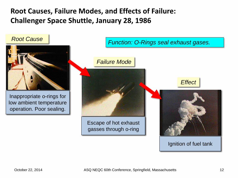
Root Causes, Failure Modes, and Effects of Failure: Challenger Space Shuttle, January 28, 1986
12
Failure Mode
Escape of hot exhaust
gasses through o-ring
Root Cause
Inappropriate o-rings for
low ambient temperature
operation. Poor sealing.
Effect
Ignition of fuel tank
Function: O-Rings seal exhaust gases.
October 22, 2014 ASQ NEQC 60th Conference, Springfield, Massachusetts
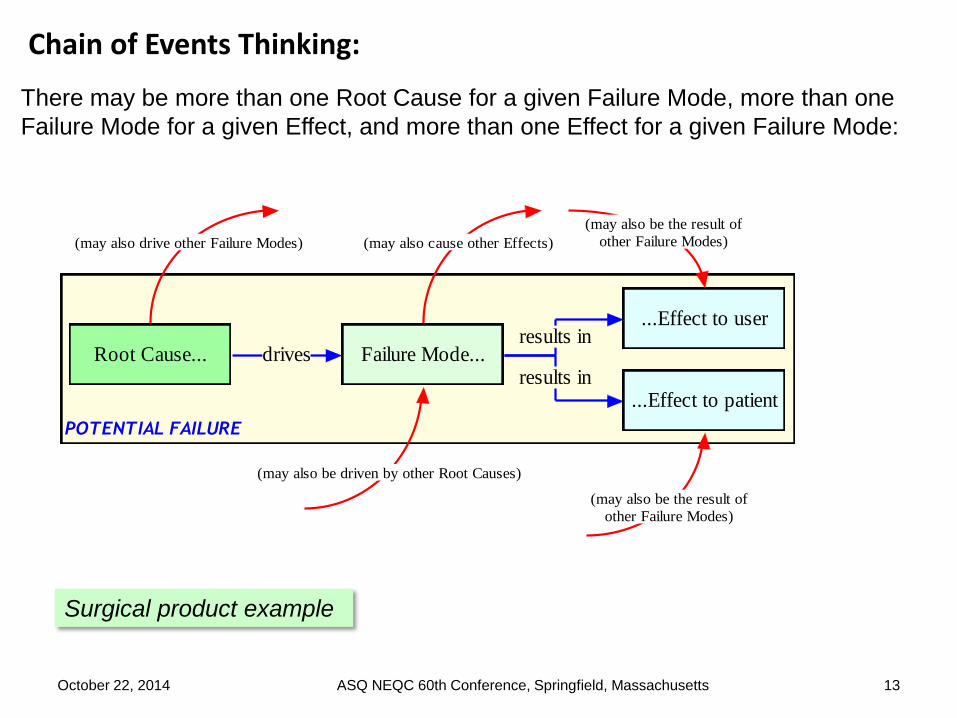
Chain of Events Thinking:
13
There may be more than one Root Cause for a given Failure Mode, more than one
Failure Mode for a given Effect, and more than one Effect for a given Failure Mode:
POTENTIAL FAILURE
Root Cause... Failure Mode...
...Effect to user
...Effect to patient
drivesresults in
results in
(may also be driven by other Root Causes)
(may also cause other Effects)
(may also be the result of
other Failure Modes)
(may also be the result of
other Failure Modes)(may also drive other Failure Modes)
Surgical product example
October 22, 2014 ASQ NEQC 60th Conference, Springfield, Massachusetts

Chain of Events Thinking and the “Window of Consideration”
14
Best choice for Window of Consideration
Speculative SpeculativeLikely EffectTarget of C/A Root Cause Failure Mode
Note that the “Patient injury” and “Legal Action” results are speculative and depend
on factors outside the chain of failure. Likewise with the training of the designer. The
appropriate window, providing the most useful information is shown in the blue box.
Insufficient material
finish spec’d for Pin
Excessive friction,
pawl binds on pin
during use
Instrument remains
locked on tissue
Inadequate training
of designer on
materials or
mechanism
Patient injury
Legal action against
hospital or
company
October 22, 2014 ASQ NEQC 60th Conference, Springfield, Massachusetts

Root Cause: Pitfalls and Pointers
15
Material softens with use Material deforms under load
Too much clearance Potential mechanical interference
Electrical overstress Rough surface finish
Leads are incorrect length for application
Material yellows with age
Material too brittle Specified lubricant is inadequate for product life
Pitfalls
Do not “blame” the environment:
NOT: The dishwasher caused the stress crack at the interface.
RATHER: The material chosen degrades in the dishwasher.
Avoid vague responses, such as “incorrect geometry”, or “improper tolerancing”.
Do not include Root Causes due to manufacturing errors or defective components—assume product is built to the design, but design may not be optimized.
Potential Root Cause:Material Chosen inadequate for dishwasher
environment (becomes brittle)
Dishwasher
Some Examples:
Pointers
Keep in mind the Usage Environment & Reasonable Abuse
October 22, 2014 ASQ NEQC 60th Conference, Springfield, Massachusetts

Failure Mode: Pitfalls and Pointers
16
Function: Support the cup when
lifted by the user
Failure Mode:Handle cracks / fractures at
cup interface
Element: Handle
Pitfall:Confusing the Failure Mode with Root Cause or Effect.
For Root Cause, ask yourself ‘What is wrong with the design that might cause a problem?’ The answers usually include words that involve geometry and/or materials. Examples are; “inadequate strength”, “inadequate clearance/interference”, “too large”, “too soft”, “unsuitable for environment”.
For Failure Mode, ask yourself ‘What happens to the instrument itself as a result of the design issue?’. The answers usually include words like; “fractures”, “loosens”, “corrodes”, “deforms”, “detaches”, “jams”.
Some Examples:
Delamination Deformed
Unintentional Input Cracked
Fractured Loosened
JammedOxidized
Open Circuit
Short to Ground
Pointer:Having very clear and concise functions really helps thebrainstorming process because it naturally lends itself toFailure Modes and Root Causes.
October 22, 2014 ASQ NEQC 60th Conference, Springfield, Massachusetts
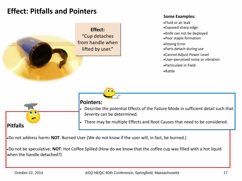
Effect: Pitfalls and Pointers
17
Effect: “Cup detaches
from handle when lifted by user.”
Pitfalls
Do not address harm: NOT: Burned User (We do not know if the user will, in fact, be burned.)
Do not be speculative: NOT: Hot Coffee Spilled (How do we know that the coffee cup was filled with a hot liquid when the handle detached?)
Some Examples:
Fluid or air leakExposed sharp edge
Knife can not be deployedPoor staple formation
Dosing ErrorParts detach during use
Cannot Adjust Power LevelUser-perceived noise or vibration
Particulate in Field
Rattle
Pointers: Describe the potential Effects of the Failure Mode in sufficient detail such that
Severity can be determined.
There may be multiple Effects and Root Causes that need to be considered.
October 22, 2014 ASQ NEQC 60th Conference, Springfield, Massachusetts
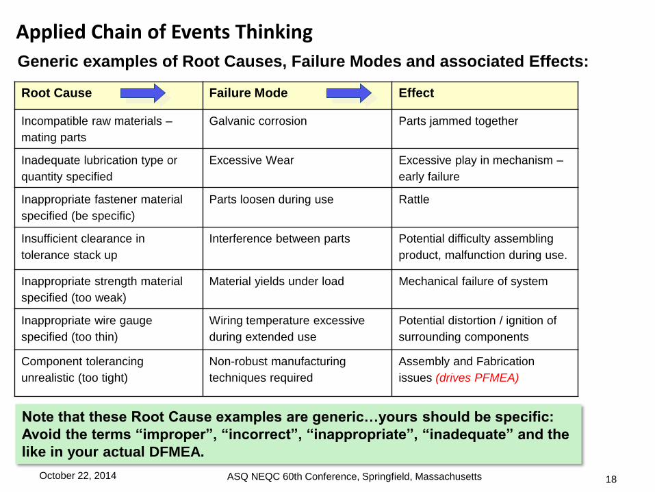
Applied Chain of Events Thinking
Root Cause Failure Mode Effect
Incompatible raw materials –
mating parts
Galvanic corrosion Parts jammed together
Inadequate lubrication type or
quantity specified
Excessive Wear Excessive play in mechanism –
early failure
Inappropriate fastener material
specified (be specific)
Parts loosen during use Rattle
Insufficient clearance in
tolerance stack up
Interference between parts Potential difficulty assembling
product, malfunction during use.
Inappropriate strength material
specified (too weak)
Material yields under load Mechanical failure of system
Inappropriate wire gauge
specified (too thin)
Wiring temperature excessive
during extended use
Potential distortion / ignition of
surrounding components
Component tolerancing
unrealistic (too tight)
Non-robust manufacturing
techniques required
Assembly and Fabrication
issues (drives PFMEA)
18
Generic examples of Root Causes, Failure Modes and associated Effects:
Note that these Root Cause examples are generic…yours should be specific:
Avoid the terms “improper”, “incorrect”, “inappropriate”, “inadequate” and the
like in your actual DFMEA.
October 22, 2014 ASQ NEQC 60th Conference, Springfield, Massachusetts

Function Root Cause Failure Mode Effect
Length(s) of
tubing
Incorrect lengths
defined by design
input.
Incorrect lengths Lengths not correct for application
Application
Step
Root Cause Failure Mode Effect
Surgeon
places
instrument
through tube
Tubing length too
long
Instrument does not
protrude sufficiently from
tubing for application
Inadequate maneuverability of
instrument
19
This is more of an AFMEA and Voice-of-Customer issue. Why did we design something
to an incorrect size? The description of the Component Function is also vague. Further,
the Failure Mode and Effect do not add any value. If the item was moved to AFMEA, it
might look like this:
October 22, 2014 ASQ NEQC 60th Conference, Springfield, Massachusetts
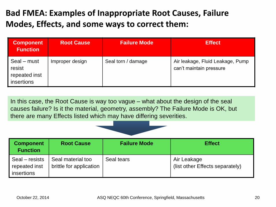
Component
Function
Root Cause Failure Mode Effect
Seal – must
resist
repeated inst
insertions
Improper design Seal torn / damage Air leakage, Fluid Leakage, Pump
can’t maintain pressure
Component
Function
Root Cause Failure Mode Effect
Seal – resists
repeated inst
insertions
Seal material too
brittle for application
Seal tears Air Leakage
(list other Effects separately)
20
In this case, the Root Cause is way too vague – what about the design of the seal
causes failure? Is it the material, geometry, assembly? The Failure Mode is OK, but
there are many Effects listed which may have differing severities.
October 22, 2014 ASQ NEQC 60th Conference, Springfield, Massachusetts
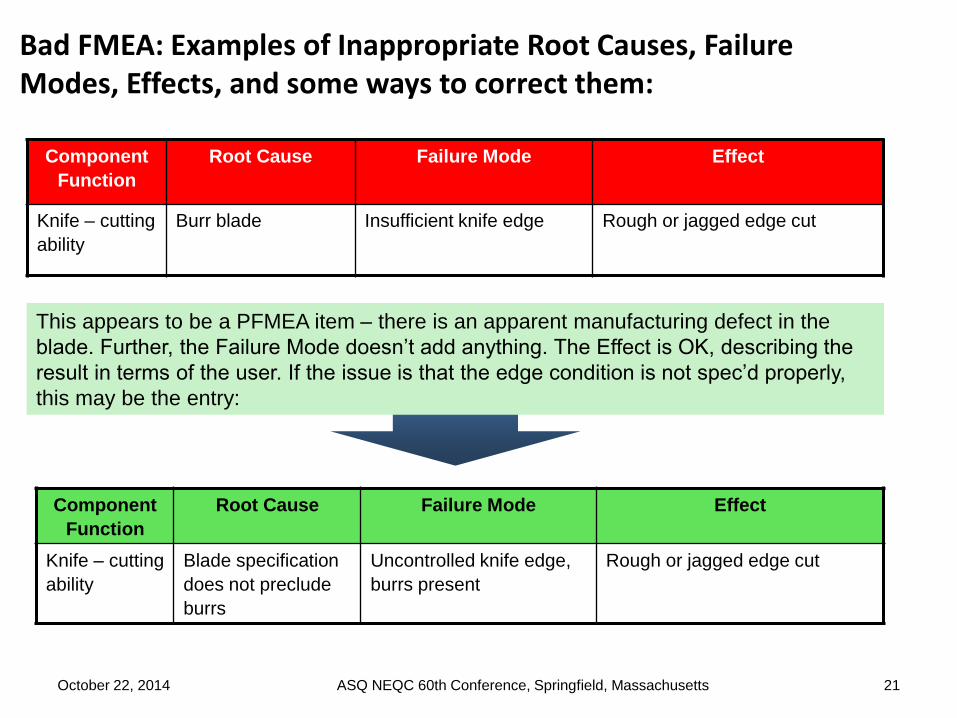
Component
Function
Root Cause Failure Mode Effect
Knife – cutting
ability
Burr blade Insufficient knife edge Rough or jagged edge cut
Component
Function
Root Cause Failure Mode Effect
Knife – cutting
ability
Blade specification
does not preclude
burrs
Uncontrolled knife edge,
burrs present
Rough or jagged edge cut
21
This appears to be a PFMEA item – there is an apparent manufacturing defect in the
blade. Further, the Failure Mode doesn’t add anything. The Effect is OK, describing the
result in terms of the user. If the issue is that the edge condition is not spec’d properly,
this may be the entry:
October 22, 2014 ASQ NEQC 60th Conference, Springfield, Massachusetts
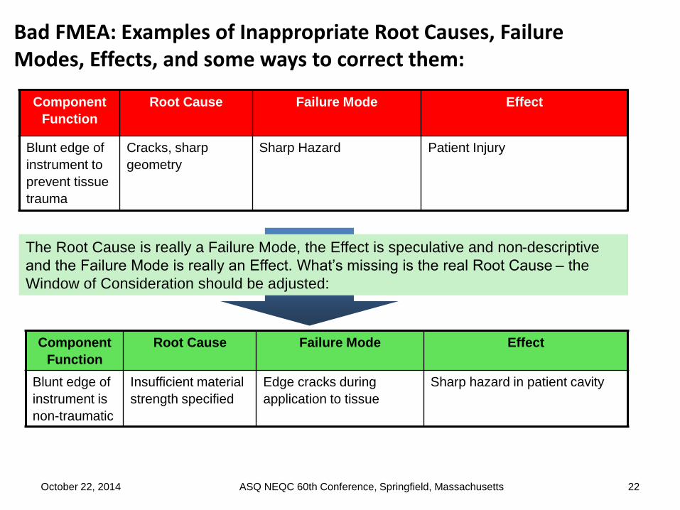
Component
Function
Root Cause Failure Mode Effect
Blunt edge of
instrument to
prevent tissue
trauma
Cracks, sharp
geometry
Sharp Hazard Patient Injury
Component
Function
Root Cause Failure Mode Effect
Blunt edge of
instrument is
non-traumatic
Insufficient material
strength specified
Edge cracks during
application to tissue
Sharp hazard in patient cavity
22
The Root Cause is really a Failure Mode, the Effect is speculative and non-descriptive
and the Failure Mode is really an Effect. What’s missing is the real Root Cause – the
Window of Consideration should be adjusted:
October 22, 2014 ASQ NEQC 60th Conference, Springfield, Massachusetts

Component
Function
Root Cause Failure Mode Effect
Pusher bar
feeds clip into
jaw slots
Clip path obstructed Pusher bar buckles Instrument jams
Application
Step
Root Cause Failure Mode Effect
Squeeze
handle to feed
clip
Clip path is
obstructed by
patient anatomy
Pusher bar buckles Instrument jams
23
This is OK except for the Root Cause: What is the source of the obstruction? What is the
design related issue? If the surgeon or patient anatomy is obstructing the clip path, this
becomes an AFMEA item as shown below:
October 22, 2014 ASQ NEQC 60th Conference, Springfield, Massachusetts

1. List the Current Controls for each Chain of Events.
2. Determine the Severity, Occurrence, and Detection rating scales.
3. Assign Severity, Occurrence and Detection scores to each line item.
4. Calculate the RPN for each line item.
5. Determine Recommended Actions to reduce high RPNs and mitigate risk.
6. Take appropriate actions, record outcomes, and recalculate RPNs.
7. Review AFMEA and PFMEA to determine if additional updates to those documents are required.
Step 1 Step 2 Step 3 Step 4 Step 5 Step 6 Step 7
October 22, 2014 ASQ NEQC 60th Conference, Springfield, Massachusetts 24

Controls are systematized methods put in place to prevent or detect Failure Modes or Root
Causes before Effects occur. Controls can either prevent the Root Cause or Failure Mode
from occurring, or detect the Failure Mode prior to the Effect occurring.
Root Cause Failure Mode Effect Control
Incompatible raw
materials – mating parts
Galvanic corrosion Mechanical Failure Material Review
Inappropriate lubrication
specified
Excessive Wear Excessive play in
mechanism – early failure
Pre-production life test with
specified lubricant
Inappropriate fastener
material specified
Parts loosen during use Rattle Engineering test of fastener
strength, vibratory loading
Inappropriate tolerance
stackup
Interference between
parts
Potential difficulty
assembling product,
malfunction during use.
Tolerance study of
components based on actual
Ppk data.
Inappropriate strength
material specified
Material yields under
load
Mechanical failure of
system
Material stress / strength
testing
Inappropriate wire
gauge specified (too
thin)
Wiring temperature
excessive during
extended use
Potential fire hazard Life testing with amp and
temperature monitoring
Inappropriate
tolerancing of
component
Non-robust
manufacturing
techniques required
Assembly and Fabrication
issues (drives PFMEA)
Design review with
manufacturing to assess
fabrication difficulty
October 22, 2014 25ASQ NEQC 60th Conference, Springfield, Massachusetts

Example: Pin (component of larger assy)
Jaws remain locked
on vesselInsufficient material
finish spec’d for Pin
A B C D E F G H I J K
Ite
m #
Component / Function Potential Failure
Mode(s)
Potential Effect(s) of
Failure
Se
ve
rity
Potential Root
Cause(s)
Oc
cu
rre
nc
e
Current Design
Control(s)
Co
ntr
ol
sta
tus
De
tec
tio
n
RP
N
COMPONENT #1
1 1st Function of Component #1 0
2 2nd Function of Component #1 0
3 0
4 0
COMPONENT #2
5 1st Function of Component #2 0
6 2nd Function of Component #2 0
7 0
8 0
COMPONENT #3
9 1st Function of Component #3 0
10 2nd Function of Component #3 0
11 0
12 0
COMPONENT #4
13 1st Function of Component #4 0
14 2nd Function of Component #4 0
15 0
16 0
Insufficient material
finish spec’d for PinActuates pawlExcessive friction,
pawl binds on pin
during use
Instrument remains
locked on tissue
Test to determine
functional life of
matl finish
PIN
October 22, 2014 26ASQ NEQC 60th Conference, Springfield, Massachusetts

For the 1-10 scoring scale, the following applies:
Severity (of Effect): Given that the failure occurs, score the importance of the Effect to the customer. The Severity score must include potential safety risks if failure occurs:
1=Not severe: Customer will barely notice failure
10=Very Severe: Effect may be life threatening
Occurrence (of Cause / Failure Mode / Effect): The frequency with which a given Root Cause occurs and creates the Failure Mode, resulting in the Effect:
1=Unlikely to occur
10=Will occur frequently
Detection (effectiveness of Current Design Controls): The ability of the current controls to prevent the Cause(s) or detect the Failure Modes:
1=Highly likely to Prevent / Detect,
10=Not likely at all to Prevent / Detect
Note the relationship between the prevention aspect of the Current Controls and
the Occurrence score. A Current Control which effectively prevents the occurrence
of the Root Cause or Failure Mode will force a low Occurrence score.
October 22, 2014 ASQ NEQC 60th Conference, Springfield, Massachusetts 27
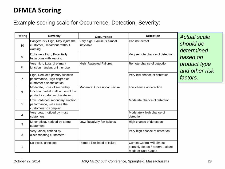
Example scoring scale for Occurrence, Detection, Severity:
Rating Severity Occurrence Detection
10
Dangerously High, May injure the
customer, Hazardous without
warning.
Can not detect
9Extremely High, Potentially
hazardous with warning.
Very remote chance of detection
8Very high, Loss of primary
function, renders unfit for use.
Remote chance of detection
7
High, Reduced primary function
performance, High degree of
customer dissatisfaction
Very low chance of detection
6
Moderate, Loss of secondary
function, partial malfunction of the
product - customer dissatisfied.
Low chance of detection
5
Low, Reduced secondary function
performance, will cause the
customers to complain
Moderate chance of detection
4Very Low, noticed by most
customers
Moderately high chance of
detection
3Minor effect, noticed by some
customers
High chance of detection
2
Very Minor, noticed by
discriminating customers
Very high chance of detection
1
No effect, unnoticed Remote likelihood of failure Current Control will almost
certainly detect / prevent Failure
Mode or Root Cause
Low: Relatively few failures
Moderate: Occasional Failure
High: Repeated Failures
Very high: Failure is almost
inevitable
Actual scale
should be
determined
based on
product type
and other risk
factors.
October 22, 2014 ASQ NEQC 60th Conference, Springfield, Massachusetts 28
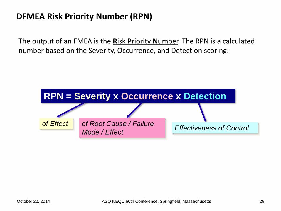
The output of an FMEA is the Risk Priority Number. The RPN is a calculated number based on the Severity, Occurrence, and Detection scoring:
of Effect of Root Cause / Failure
Mode / EffectEffectiveness of Control
RPN = Severity x Occurrence x Detection
October 22, 2014 ASQ NEQC 60th Conference, Springfield, Massachusetts 29

Example: Pin (component of larger assy)
Jaws remain locked
on vesselInsufficient material
finish spec’d for Pin
A B C D E F G H I J K
Ite
m #
Component / Function Potential Failure
Mode(s)
Potential Effect(s) of
Failure
Se
ve
rity
Potential Root
Cause(s)
Oc
cu
rre
nc
e
Current Design
Control(s)
Co
ntr
ol
sta
tus
De
tec
tio
n
RP
N
COMPONENT #1
1 1st Function of Component #1 0
2 2nd Function of Component #1 0
3 0
4 0
COMPONENT #2
5 1st Function of Component #2 0
6 2nd Function of Component #2 0
7 0
8 0
COMPONENT #3
9 1st Function of Component #3 0
10 2nd Function of Component #3 0
11 0
12 0
COMPONENT #4
13 1st Function of Component #4 0
14 2nd Function of Component #4 0
15 0
16 0
Insufficient material
finish spec’d for PinActuates pawlExcessive friction,
pawl binds on pin
during use
Jaws remain locked
on vessel
Test to determine
functional life of
matl finish
PIN
9 3 542
October 22, 2014 30ASQ NEQC 60th Conference, Springfield, Massachusetts

Q: How do you determine what RPN level is actionable?
A: The preferred method is Pareto principle: Create a Pareto diagram of your
RPNs and address the top 10-30 percent first. Note that any Severity score of 9
or 10 should be considered for action even with a low Occurrence / Detection
score. The actionable RPN may be different for each product / project.
Sample
RPNs and
decisions.
Your
decisions
may be
different!
Sev Occ Det RPN Result Actions
1 2 1 2 Best Design Possible Actions not required.
2 2 10 40 A rare but undetectable failure with
little impact to the user
Action may be required. Determine if
detection / prevention can be improved
10 1 1 10 Catastrophic failure which rarely
happens and is detectable /
preventable
Action may be required. Review item to
determine if redesign is required to reduce
severity
10 2 10 200 Catastrophic and undetectable
failure which rarely reaches user
Action required. Improve detection or
redesign to reduce severity
3 10 2 60 Minor failure which occurs
frequently, effective prevention /
detection
Action required. Redesign to reduce
occurrence.
3 10 10 300 Minor frequent failure,
undetectable, unpreventable
Action required. Redesign / improve
detection
10 5 4 200 Catastrophic and relatively
frequent failure, marginally
effective controls
Action required. Redesign to reduce severity
10 10 10 1000 Catastrophic and frequent failure
with which will reach the user
Hold project
31ASQ NEQC 60th Conference, Springfield, MassachusettsOctober 22, 2014
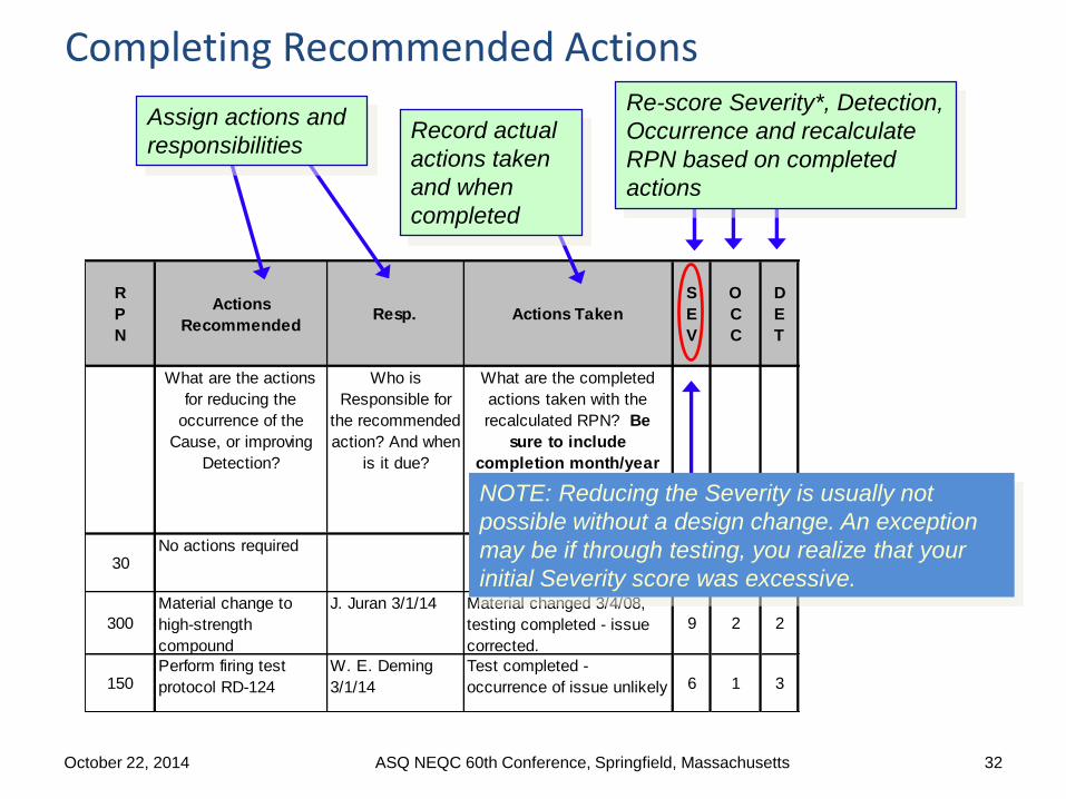
R
P
N
Actions
RecommendedResp. Actions Taken
S
E
V
O
C
C
D
E
T
What are the actions
for reducing the
occurrence of the
Cause, or improving
Detection?
Who is
Responsible for
the recommended
action? And when
is it due?
What are the completed
actions taken with the
recalculated RPN? Be
sure to include
completion month/year
30No actions required
6 5 1
300
Material change to
high-strength
compound
J. Juran 3/1/14 Material changed 3/4/08,
testing completed - issue
corrected.
9 2 2
150Perform firing test
protocol RD-124
W. E. Deming
3/1/14
Test completed -
occurrence of issue unlikely 6 1 3
Completing Recommended Actions
Assign actions and
responsibilitiesRecord actual
actions taken
and when
completed
Re-score Severity*, Detection,
Occurrence and recalculate
RPN based on completed
actions
NOTE: Reducing the Severity is usually not
possible without a design change. An exception
may be if through testing, you realize that your
initial Severity score was excessive.
October 22, 2014 ASQ NEQC 60th Conference, Springfield, Massachusetts 32

Tips for doing Better DFMEAs
33
Use as a Design Tool:
• “Bite-Sized” vs. Monolithic: A central tenant for
efficient product development is to improve flow by
reducing “batch” sizes.
• Tool vs. Checkbox: Design FMEA is not a
beneficial tool if used solely as a “check-box”
requirement.
• Tool vs. Tracker: A common misapplication of the tool is to use the
Design FMEA as a “tracker” to capture and track every risk mitigation
action.
• Early and Throughout vs. Last Minute: A Good DFMEA encourages
brainstorming potential issues early in the design cycle and improving
the design throughout testing and evaluation.
October 22, 2014 ASQ NEQC 60th Conference, Springfield, Massachusetts

Tips for doing Better DFMEAs
34 |
Efficient and Intuitive:
• Who?: Team effort vs. Designer’s Responsibility: A Good DFMEA
might consider a more balanced approach to individual responsibilities
and team meeting.
• Appropriate vs. Overly-Detailed: A Good FMEA does not
necessarily break everything down to the component level
• Non-Intuitive vs. “Oh, this make sense!”:
• “Chain of Events” Thinking
• Scoring Afterwards
• Replacing “Occurrence” with “Likelihood”
• Remove Detection
• Reduced Scales
October 22, 2014ASQ NEQC 60th Conference,
Springfield, Massachusetts
Tips for doing Better DFMEAs
35
Leverage a Facilitator:
• Pre-work. Stay ahead of the team. Complete
the framework for the meeting agenda ahead
of time.
• Agenda: Have an agenda and state it at the
beginning of each meeting:
• Clear Objectives: Write the high level meeting objectives in bold letters
on white board or flip chart.
• No open laptop computers in the meeting, other than the facilitator’s:
Phones and BlackBerrys put away. Do not waste the group’s time typing
and formatting to perfection.
• Visual Room: Place definitions of key terms as well as criteria charts for
Severity and Likelihood on the wall.
• JIT Training: Make sure the group understands the basic terminology
and “chain of events” concept before brainstorming.
October 22, 2014 ASQ NEQC 60th Conference, Springfield, Massachusetts

Tips for doing Better DFMEAs
36
Leverage a Facilitator:
• Brainstorm first: Then cover Current Controls, and then score/rank.
• Focus: Keep the conversation on track.
• Engaged Participants: Call on participants by name with a pertinent
question if they have not contributed in a while.
• Have Fun: Candy helps – it is important to keep the team positive.
• Administration: Keep a parking lot to capture off topic action items and
take five minutes at the end of the meeting getting feedback on the
overall process.
• Parts: Bring examples of the
components / product or similar products
to encourage brainstorming.
October 22, 2014 ASQ NEQC 60th Conference, Springfield, Massachusetts
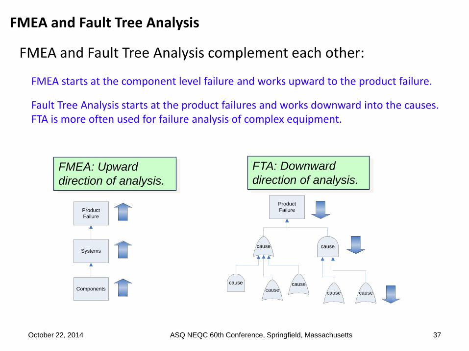
FMEA and Fault Tree Analysis
FMEA and Fault Tree Analysis complement each other:
FMEA starts at the component level failure and works upward to the product failure.
Fault Tree Analysis starts at the product failures and works downward into the causes. FTA is more often used for failure analysis of complex equipment.
37
FMEA: Upward
direction of analysis.
FTA: Downward
direction of analysis.
cause cause
Product
Failure
cause
causecause
cause cause
Product
Failure
Systems
Components
October 22, 2014 ASQ NEQC 60th Conference, Springfield, Massachusetts
38
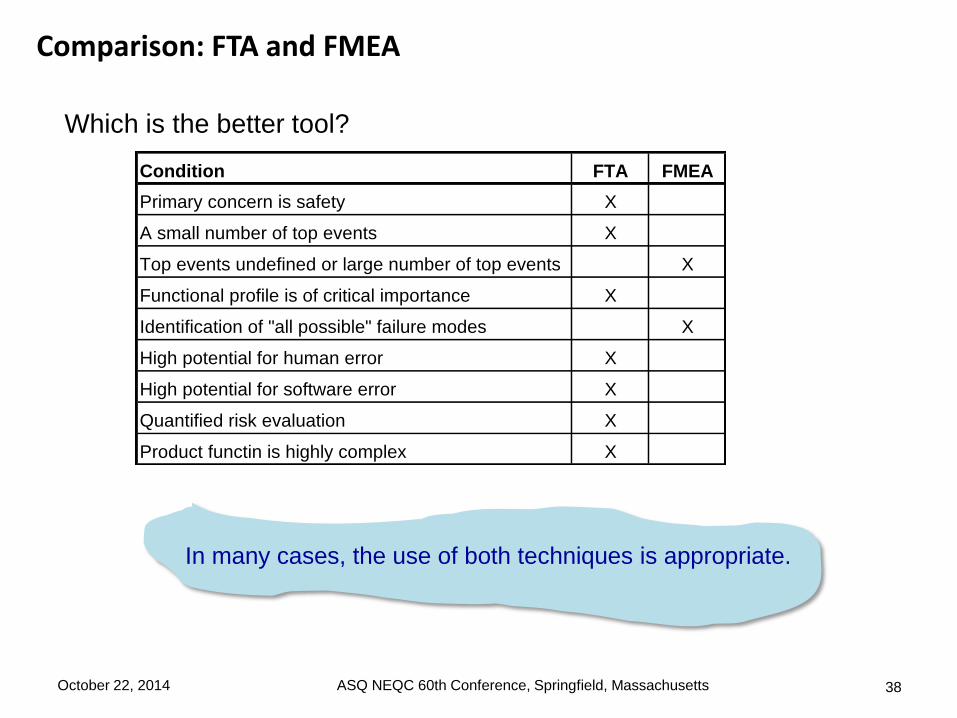
Which is the better tool?
Condition FTA FMEA
Primary concern is safety X
A small number of top events X
Top events undefined or large number of top events X
Functional profile is of critical importance X
Identification of "all possible" failure modes X
High potential for human error X
High potential for software error X
Quantified risk evaluation X
Product functin is highly complex X
In many cases, the use of both techniques is appropriate.
October 22, 2014 ASQ NEQC 60th Conference, Springfield, Massachusetts
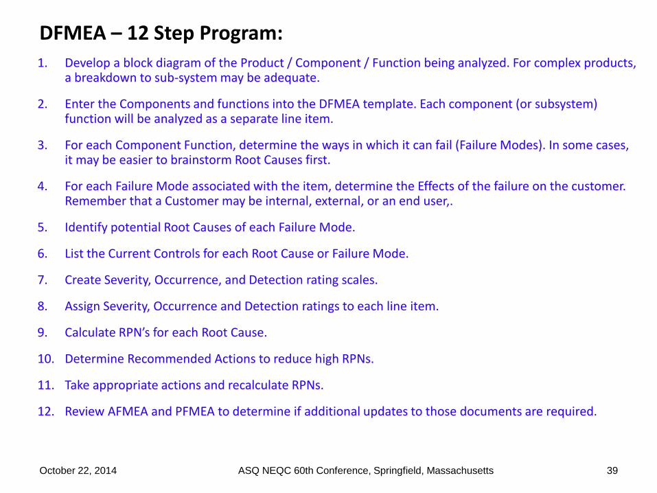
1. Develop a block diagram of the Product / Component / Function being analyzed. For complex products, a breakdown to sub-system may be adequate.
2. Enter the Components and functions into the DFMEA template. Each component (or subsystem) function will be analyzed as a separate line item.
3. For each Component Function, determine the ways in which it can fail (Failure Modes). In some cases, it may be easier to brainstorm Root Causes first.
4. For each Failure Mode associated with the item, determine the Effects of the failure on the customer. Remember that a Customer may be internal, external, or an end user,.
5. Identify potential Root Causes of each Failure Mode.
6. List the Current Controls for each Root Cause or Failure Mode.
7. Create Severity, Occurrence, and Detection rating scales.
8. Assign Severity, Occurrence and Detection ratings to each line item.
9. Calculate RPN’s for each Root Cause.
10. Determine Recommended Actions to reduce high RPNs.
11. Take appropriate actions and recalculate RPNs.
12. Review AFMEA and PFMEA to determine if additional updates to those documents are required.
October 22, 2014 ASQ NEQC 60th Conference, Springfield, Massachusetts 39
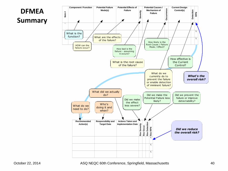
DFMEA Summary
40
Recommended
Action(s)
Responsibility and
Target Date
Actions Taken and
Implementation Date
Re
v S
ev
eri
ty
Re
v O
cc
ur.
Re
v D
ete
cti
on
Re
v R
PN
Ite
m #
Component / Function Potential Failure
Mode(s)
Potential Effects of
Failure
Se
ve
rity
Potential Causes /
Mechanism of
Failure
Oc
cu
rre
nc
e
Current Design
Control(s)
De
tec
tio
n
RP
N
What is the
function?
HOW can thefailure occur?
What are the effects
of the failure?
How bad is thefailure - assuming
it occurs?
What is the root cause
of the failure?
How likely is theRoot Cause / Failure
Mode / Effect?
What do we
currently do to
prevent the failure
or enable detection
of imminent failure?
How effective is
the Current
Control?
What's theoverall risk?
What do we
need to do?
Who's
doing it and
when?
What did we actually
do?
Did we make
the effect
less severe?
Did we make the
Potential Failure less
likely?
Did we prevent the
failure or improve
detectability?
Did we reducethe overall risk?
October 22, 2014 ASQ NEQC 60th Conference, Springfield, Massachusetts

October 22, 2014 ASQ NEQC 60th Conference, Springfield, Massachusetts 41
Thank you
Questions ?

October 22, 2014 ASQ NEQC 60th Conference, Springfield, Massachusetts 42