Integrated Design and Multiobjctive Optimization -...
12
INTEGRATED DESIGN AND MULTIOBJECTIVE OPTIMIZATION APPROACH TO SHIP DESIGN A Papanikolaou, National Technical University of Athens, Athens/Greece S Harries, FRIENDSHIP SYSTEMS, Potsdam/Germany M Wilken, Germanischer Lloyd, Hamburg/Germany G Zaraphonitis, National Technical University of Athens, Athens/Greece SUMMARY An integrated design and multiobjective optimization approach to ship design is herein presented. It integrates methods and software tools for the simultaneous evaluation of key measures of merit in the early phase of ship design. The implemented approach is herein applied to the design of an Aframax tanker for which a variety of parameters related to payload, steel weight, strength, oil outflow, stability and hydrodynamics were considered within an integrated multiobjective design and optimization procedure. Required Freight Rates (RFR), Oil Outflow Index (OOI), Energy Efficiency Design Index (EEDI) and maximum speed for given main engine margins were determined so as to rank design alternatives. Formal exploration and exploitation strategies were utilized to investigate the design space and, subsequently, advance competing design proposals into certain directions such as maximum energy efficiency, attainable speed and environmental protection in case of accidents. The paper focuses on the integration of design methods, of related software tools and optimization, utilizing the design of a tanker as an elaborated demonstration example to illustrate the holistic view of the adopted approach. 1. INTRODUCTION Ship design was in the past considered a sequential process that may be depicted by the classical design spiral, Fig.1 (Evans, 1959). Even though this represents an idealization of the actual design process, the traditional work flow was indeed to study one issue at a time and to advance in the design step by step, undertaking modifications and establishing refinements iteratively. Particularly when looking at a complex system, like ship design, with many relationships and dependencies, it is beyond any single individual's capacity to keep in mind and consider all options, their pros and cons and consequences. A modern, integrated approach to ship design, as depicted on the right side of Fig.1, brings together all key aspects of a design task at the same time. A synthesis model of Computer Aided Engineering (CAE), integrating techno-economical databases, calculation and optimization algorithms, modern GUI and information exchange systems allows the exploration of the design space to a much larger extent and leads to new insights and promising new design alternatives. The present paper describes the essential features of such an integrated design software platform and demonstrates its implementation in practice by looking at an Aframax tanker design for Caribbean trade The developed CAE environment was established to examine key measures of merit for a considerable number of design alternatives simultaneously: Payload, steel weight, strength, oil outflow, stability and hydrodynamics were computed by means of sophisticated simulation codes. Required freight rates (RFR), Energy Efficiency Design Index (EEDI) and maximum attainable speed for given engine output were determined so as to assess and rank variants. Figure 1: Traditional design spiral (left) vs. integrated approach (right)
Transcript of Integrated Design and Multiobjctive Optimization -...
INTEGRATED DESIGN AND MULTIOBJECTIVE OPTIMIZATION APPROACH
TO SHIP DESIGN
A Papanikolaou, National Technical University of Athens, Athens/Greece
S Harries, FRIENDSHIP SYSTEMS, Potsdam/Germany
M Wilken, Germanischer Lloyd, Hamburg/Germany
G Zaraphonitis, National Technical University of Athens, Athens/Greece
SUMMARY
An integrated design and multiobjective optimization approach to ship design is herein presented. It integrates methods
and software tools for the simultaneous evaluation of key measures of merit in the early phase of ship design. The
implemented approach is herein applied to the design of an Aframax tanker for which a variety of parameters related to
payload, steel weight, strength, oil outflow, stability and hydrodynamics were considered within an integrated
multiobjective design and optimization procedure. Required Freight Rates (RFR), Oil Outflow Index (OOI), Energy
Efficiency Design Index (EEDI) and maximum speed for given main engine margins were determined so as to rank
design alternatives. Formal exploration and exploitation strategies were utilized to investigate the design space and,
subsequently, advance competing design proposals into certain directions such as maximum energy efficiency, attainable
speed and environmental protection in case of accidents. The paper focuses on the integration of design methods, of
related software tools and optimization, utilizing the design of a tanker as an elaborated demonstration example to
illustrate the holistic view of the adopted approach.
1. INTRODUCTION
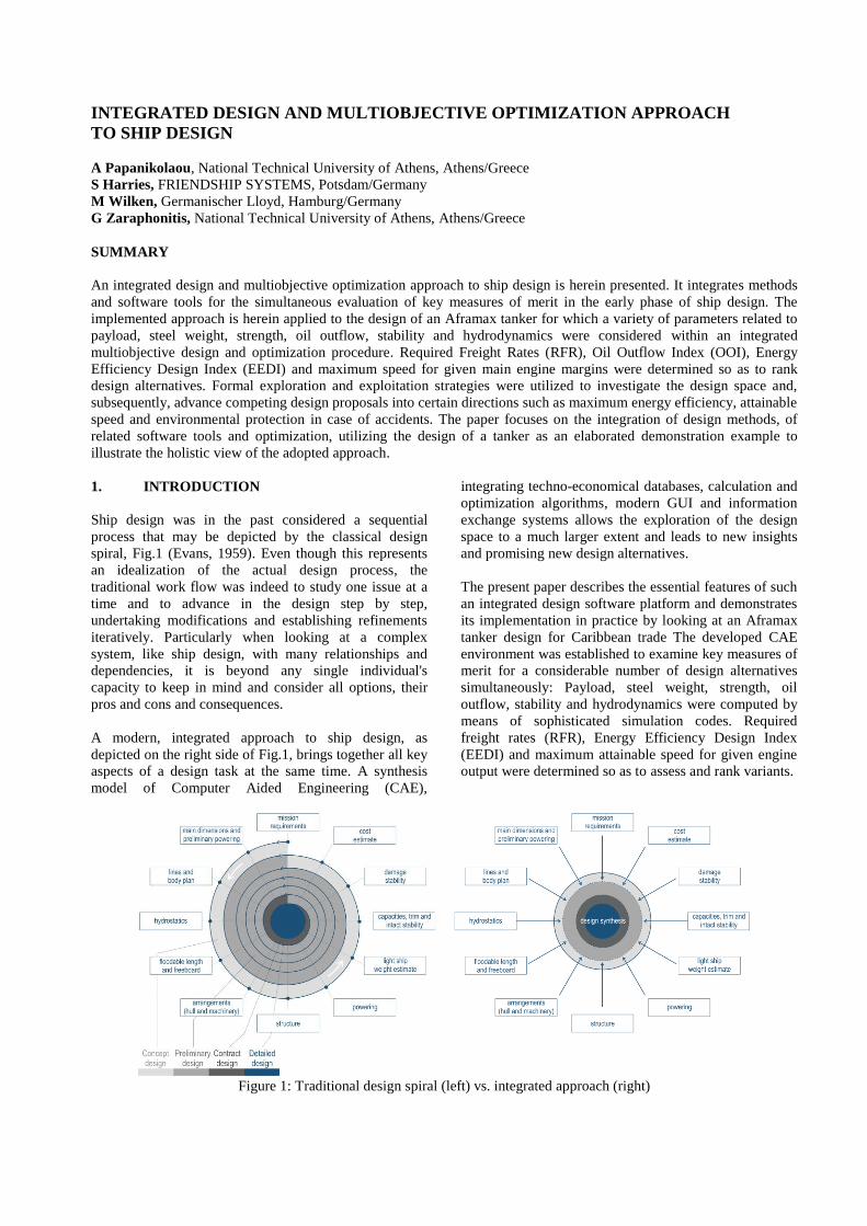
Ship design was in the past considered a sequential
process that may be depicted by the classical design
spiral, Fig.1 (Evans, 1959). Even though this represents
an idealization of the actual design process, the
traditional work flow was indeed to study one issue at a
time and to advance in the design step by step,
undertaking modifications and establishing refinements
iteratively. Particularly when looking at a complex
system, like ship design, with many relationships and
dependencies, it is beyond any single individual's
capacity to keep in mind and consider all options, their
pros and cons and consequences.
A modern, integrated approach to ship design, as
depicted on the right side of Fig.1, brings together all key
aspects of a design task at the same time. A synthesis
model of Computer Aided Engineering (CAE),
integrating techno-economical databases, calculation and
optimization algorithms, modern GUI and information
exchange systems allows the exploration of the design
space to a much larger extent and leads to new insights
and promising new design alternatives.
The present paper describes the essential features of such
an integrated design software platform and demonstrates
its implementation in practice by looking at an Aframax
tanker design for Caribbean trade The developed CAE
environment was established to examine key measures of
merit for a considerable number of design alternatives
simultaneously: Payload, steel weight, strength, oil
outflow, stability and hydrodynamics were computed by
means of sophisticated simulation codes. Required
freight rates (RFR), Energy Efficiency Design Index
(EEDI) and maximum attainable speed for given engine
output were determined so as to assess and rank variants.
Figure 1: Traditional design spiral (left) vs. integrated approach (right)

2. SHIP DESIGN OPTIMIZATION
Inherently coupled with the design process is design
optimization, namely the selection of the best solution
out of many feasible ones on the basis of a criterion, or
rather a set of criteria. A systemic approach to ship
design may consider the ship as a complex system
integrating a variety of subsystems and their components,
e.g. subsystems for cargo storage and handling,
energy/power generation and ship propulsion,
accommodation of crew/passengers and ship navigation.
Independently, considering that ship design should
actually address the whole ship’s life cycle, it may be
split into various stages that are traditionally composed
of the concept/preliminary design, the contractual and
detailed design, the ship construction/fabrication process,
ship operation for an economic life and
scrapping/recycling. It is evident that the optimal ship
with respect to her whole life cycle is the outcome of a
holistic optimization of the entire, above defined ship
system for its life-cycle (Papanikolaou, [13]).
Inherent to ship design optimization are also the
conflicting requirements resulting from the design
constraints and optimization criteria (merit or objective
functions), reflecting the interests of the various ship
design stake holders: ship owners/operators, ship builders,
classification society/coast guard, regulators, insurers,
cargo owners/forwarders, port operators etc. Assuming a
specific set of requirements (usually the shipowner’s
requirements for merchant ships or mission statement for
naval ships), a ship needs to be optimized for lowest
construction cost, for highest operational efficiency or
lowest Required Freight Rate (RFR), for highest safety
and comfort of passengers/crew, for satisfactory
protection of cargo and the ship herself as hardware and
last but not least, for minimum environmental impact,
particularly for oil carriers with respect to marine
pollution in case of accidents. Recently, even aspects of
ship engine emissions and air pollution need to be
considered in the optimization of ship design and
operation. Many of these requirements are clearly
conflicting and a decision regarding the optimal ship
design needs to be rationally made (Fig. 2).
3. DEMONSTRATION EXAMPLE
In recent time, shipping industry's major ecological
concerns are related to energy/ fuel consumption and
associated green-house gas emissions. This comes on top
of longstanding concerns regarding accidental oil
pollution, particularly by crude oil carriers. The
introduction of the EEDI as put forward by the [11]
raises both awareness and triggers efforts for higher
energy efficiency, while high bunker prices continue to
excite economic pressure on the operators. A recent
comprehensive study on the risk of large oil tankers
showed that the potential loss of cargo is dominated by
grounding and collision accidents, along with fire and
explosions, [10]. Enlarged double hull width and double
bottom height, enhanced compartmentation and varying
size of tanks can lead to improved environmental
protection, without compromising ship’s efficiency, as
elaborated by Papanikolaou et al. [12].
An analysis using Lloyd’s Register Fairplay WSE
Database revealed that one fifth of the existing Aframax
tanker tonnage would be older than 15 years by 2012.
Even though current tanker capacity appears to outweigh
anticipated demand of oil transport, the fleet's ageing is
likely to trigger replacements.
It is therefore safe to assume that new tanker designs will
be sought in the near future. However, it is not obvious
what will be the main driving forces:
Safer shipping by containing or mitigating oil
outflow in case of an accident,
Greener operations by reducing emissions per ton-
mile of cargo,
Smarter business by increasing returns (higher cargo
capacity and lower fuel consumption).
A reasonable combination is likely to be favored over an
extreme, depending on the specific situation and
preference of the stake holders. The more high-quality
design data are available the easier it is to understand
opposing influences, come to a sound judgment and
choose the BEST compromise (Sames et al, 2011).
shift of bulkhead heads
innerbottom height COT1
frame spacing
COT1COT2COT3COT4COT5COT6
innerbottom height COT6-2
shift of bulkhead heads
innerbottom height COT1
frame spacing
COT1COT2COT3COT4COT5COT6
innerbottom height COT6-2
width of hopper plate
side shell width
innerbottom height
angle of hopper platewidth of hopper plate
side shell width
innerbottom height width of hopper plate
side shell width
innerbottom height
angle of hopper plate
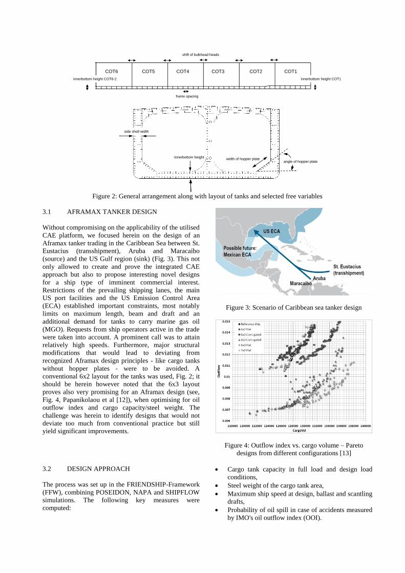
Figure 2: General arrangement along with layout of tanks and selected free variables
3.1 AFRAMAX TANKER DESIGN
Without compromising on the applicability of the utilised
CAE platform, we focused herein on the design of an
Aframax tanker trading in the Caribbean Sea between St.
Eustacius (transshipment), Aruba and Maracaibo
(source) and the US Gulf region (sink) (Fig. 3). This not
only allowed to create and prove the integrated CAE
approach but also to propose interesting novel designs
for a ship type of imminent commercial interest.
Restrictions of the prevailing shipping lanes, the main
US port facilities and the US Emission Control Area
(ECA) established important constraints, most notably
limits on maximum length, beam and draft and an
additional demand for tanks to carry marine gas oil
(MGO). Requests from ship operators active in the trade
were taken into account. A prominent call was to attain
relatively high speeds. Furthermore, major structural
modifications that would lead to deviating from
recognized Aframax design principles - like cargo tanks
without hopper plates - were to be avoided. A
conventional 6x2 layout for the tanks was used, Fig. 2; it
should be herein however noted that the 6x3 layout
proves also very promising for an Aframax design (see,
Fig. 4, Papanikolaou et al [12]), when optimising for oil
outflow index and cargo capacity/steel weight. The
challenge was herein to identify designs that would not
deviate too much from conventional practice but still
yield significant improvements.
Figure 3: Scenario of Caribbean sea tanker design
Figure 4: Outflow index vs. cargo volume – Pareto
designs from different configurations [13]
3.2 DESIGN APPROACH
The process was set up in the FRIENDSHIP-Framework
(FFW), combining POSEIDON, NAPA and SHIPFLOW
simulations. The following key measures were
computed:
Cargo tank capacity in full load and design load
conditions,
Steel weight of the cargo tank area,
Maximum ship speed at design, ballast and scantling
drafts,
Probability of oil spill in case of accidents measured
by IMO's oil outflow index (OOI).
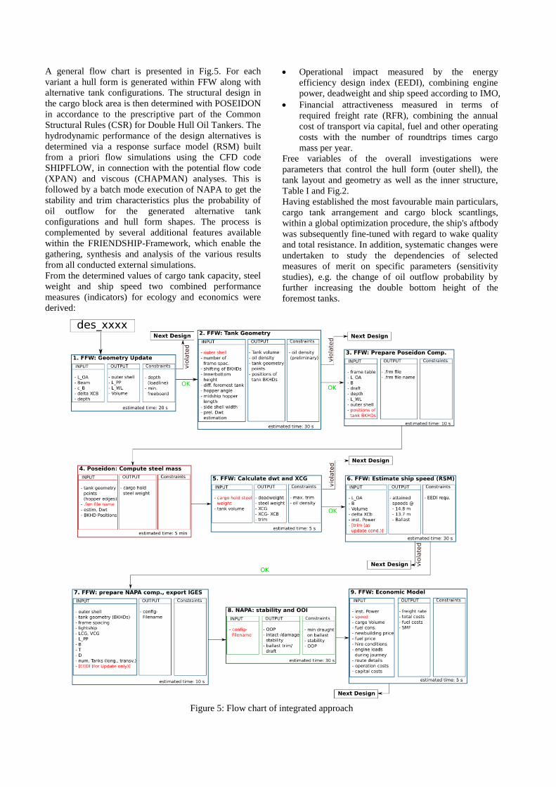
A general flow chart is presented in Fig.5. For each
variant a hull form is generated within FFW along with
alternative tank configurations. The structural design in
the cargo block area is then determined with POSEIDON
in accordance to the prescriptive part of the Common
Structural Rules (CSR) for Double Hull Oil Tankers. The
hydrodynamic performance of the design alternatives is
determined via a response surface model (RSM) built
from a priori flow simulations using the CFD code
SHIPFLOW, in connection with the potential flow code
(XPAN) and viscous (CHAPMAN) analyses. This is
followed by a batch mode execution of NAPA to get the
stability and trim characteristics plus the probability of
oil outflow for the generated alternative tank
configurations and hull form shapes. The process is
complemented by several additional features available
within the FRIENDSHIP-Framework, which enable the
gathering, synthesis and analysis of the various results
from all conducted external simulations.
From the determined values of cargo tank capacity, steel
weight and ship speed two combined performance
measures (indicators) for ecology and economics were
derived:
Operational impact measured by the energy
efficiency design index (EEDI), combining engine
power, deadweight and ship speed according to IMO,
Financial attractiveness measured in terms of
required freight rate (RFR), combining the annual
cost of transport via capital, fuel and other operating
costs with the number of roundtrips times cargo
mass per year.
Free variables of the overall investigations were
parameters that control the hull form (outer shell), the
tank layout and geometry as well as the inner structure,
Table I and Fig.2.
Having established the most favourable main particulars,
cargo tank arrangement and cargo block scantlings,
within a global optimization procedure, the ship's aftbody
was subsequently fine-tuned with regard to wake quality
and total resistance. In addition, systematic changes were
undertaken to study the dependencies of selected
measures of merit on specific parameters (sensitivity
studies), e.g. the change of oil outflow probability by
further increasing the double bottom height of the
foremost tanks.
Figure 5: Flow chart of integrated approach

Table I: Free variables and their bounds for the global optimization
Free variable Lower bound Upper bound Primary influence
Length over all (LOA) 242 m 250 m Hull form
Beam 42 m 44 m Hull form
Shift of longitudinal center of buoyancy -0.008 LPP 0.008 LPP Hull form
Block coefficient 0.8 0.885 Hull form
Depth 20.5 m 23 m Tank geometry
Inner bottom height of cargo oil tanks 2 to 6 (S+P) 2.0 m 2.7 m Tank geometry
Lifting of inner bottom of cargo oil tank 1 (S+P) 0 m 1.5 m Tank geometry
Side shell width 2.0 m 2.7 m Tank geometry
Angle of hopper plate 30° 60° Tank geometry
Width of hopper plate 4.8 m 5.8 m Tank geometry
Shift of the intermediate bulkheads (frame spacing a) -1 a +1 a Inner structure
Number of frames per tank 7 8 Inner structure
4. PARAMETRIC MODELS
4.1 HULL FORM
A fully parametric hull model was developed within
FFW for typical tanker hull forms, Fig. 6. The model is
divides the hull into into forebody, parallel midbody and
aftbody. While the forebody and the aftbody are created
using meta-surfaces, the parallel midbody is a simple
ruled surface for connection.
Basic curves for points, tangents and integral values are
employed to define the shape of the hull surfaces. The
basic curves depend on global variables, e.g. length
between perpendicular (LPP), and local variables which
influence only small regions. The shapes of the basic
curves are controlled by specifying the tangents at their
start and end positions, respectively, as well as specific
areas between the curve and an axis of reference. In
special cases, for example the waterlines in the aftbody,
additional points in the middle are utilized along with
associated tangent information.
The forebody is realized using one single meta-surface
with rotating sections, with the center of rotation at the
intersection of the aft end of the forebody, the midship
plane and the flat of bottom. In the aftbody region several
surface patches are combined, using sections (x constant)
as input to the meta-surfaces except for the aft bulb
which features a surface built on waterlines (z constant)
to ensure tangent continuity at the transition to the
adjacent surface.
Figure 6: Fully parametric hull model for a tanker
For hydrodynamic analyses, see section 4.2, the length,
beam, longitudinal position of the center of buoyancy
(XCB) and displacement volume were changed
systematically. While length and beam of the hull form
are global parameters of the fully parametric model, the
variations of XCB and displacement were realized by
means of a Generalized Lackenby for partially
parametric modifications, [1] & [2]. Local parameters

defining the shape of the aftbody's basic curves were
changed during the hydrodynamic fine tuning. In this
phase 12 local parameters were varied, for instance the
fullness of the diagonal starting in the forward clearance
point, the forward clearance of the propeller and the
fullness of the aft bulb curve in the midship plane (Tillig,
2010).
An existing geometry model from previous studies by
Papanikolaou et al. [13] was taken as a good starting
point for the design task and the parametric model was
adjusted to closely resemble the existing hull form.
Generating a new variant then simply meant changing
the selected set of parameters.
4.2 TANK ARRANGEMENT
The cargo tanks were generated within the FFW using
feature technology, e.g. [4]. The tanks are generated such
that maximum cargo volume is realized while ensuring a
minimum distance to the hull form, e.g. 2 m. The feature
takes the hull form, the minimum distance of the inner
structure to the hull (outer shell) and the longitudinal
position of the engine room's bulkhead as inputs. The
collision bulkhead's position is computed according to
IMO rules.
During the global optimization the side shell width at
deck height, the double bottom height at amidships, the
angle and width of the hopper plate and the step in the
double bottom towards the foremost tank were changed.
The bulkhead positions were moved discretely according
to the frame positions. The total number of frames was
controlled by specifying the number of frames per tank.
The first tanks (COT1) and the last tanks (COT6) were
flexible in length by allowing shifts of the bulkhead
positions by one frame distance forward or aft, Fig. 2.
The tanks associated with a specific design variant were
represented as an assembly of planar surfaces within the
FFW, Fig. 7, and transferred to NAPA by means of the
edge points for the bulkheads and hopper plates.
Figure 7: Family of parametrically generated hull forms for 6x2 cargo tank arrangements by use of the
FRIENDSHIP-Framework (FFW)
4.3 STRUCTURAL MODEL
For the structural design and strength assessment a
computational model containing all CSR relevant rules
information was needed. The model had to include
information about the main particulars of the vessel, plate
distribution and stiffener arrangement of primary and
secondary members, tank arrangement and load
definitions. This was herein accomplished by generating
the main structural design externally by GL’s
POSEIDON software. For the interface to this code, a
template database was developed, which considers
relevant to the steel structure free variables. This
template database specifies the steel structure of the
cargo tank area of an Aframax tanker with 6x2 layout
and a plate arrangement and stiffener distribution
complying with a conventional design, Fig. 8:
Figure 8: Hull structure modelled within POSEIDON
(main deck removed to show inner structure)
Vertically stiffened flat transverse bulkheads with
transverse girders,
Longitudinally stiffened main deck, hopper plate,
inner hull, inner bottom, stringer decks, longitudinal
girders,
Longitudinal bulkhead stiffened with transverse
girders,
Regularly positioned web and floor plates,
Main deck supporting transverse girders.
Using a Python interface to POSEIDON's database, the
template model is updated continuously according to the
characteristics of each generated design. An ASCII file is
provided by the FFW which includes an adaptation of the
hull form in POSEIDON's specific offset format, the
actual tank compartmentation and the free variables for
the inner structure, like the number of frames per cargo
tank.
5. ANALYSES AND SIMULATIONS
5.1 STRUCTURE AND STRENGTH
For the assessment of the structural design of generated
design alternatives the Common Structural Rules (CSR)
for Double Hull Oil Tankers was applied with their
different levels of assessment. CSR start with
prescriptive rules based on beam theory which are
followed by Finite Element Analyses (FEA) of primary
and secondary members and then finish with detailed
FEA for fatigue assessment of structural details in a hot
spot approach.
Here, only the prescriptive part of the CSR was applied
to determine the strength of the structure. In this sense
the proposed integrated approach yields a "pre-
dimensioned" tanker design that needs to be approved -
and slightly adapted - in a subsequent step to comply
fully with the CSR. The reason behind this is that model
generation for FEA is a rather sophisticated undertaking
in its own right and that corresponding simulations need
considerable resources. It was therefore decided to utilize
the prescriptive part to rank variants according to their
overall properties within the optimization process.
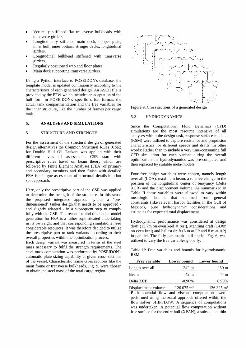
Each design variant was measured in terms of the steel
mass necessary to fulfil the strength requirements. The
steel mass computation was performed by POSEIDON's
automatic plate sizing capability at given cross sections
of the vessel. Characteristic frame cross sections like the
main frame or transverse bulkheads, Fig. 9, were chosen
to obtain the steel mass of the total cargo region.
Figure 9: Cross sections of a generated design
5.2 HYDRODYNAMICS
Since the Computational Fluid Dynamics (CFD)
simulations are the most resource intensive of all
analyses within the design task, response surface models
(RSM) were utilized to capture resistance and propulsion
characteristics for different speeds and drafts. In other
words: Rather than to include a very time-consuming full
CFD simulation for each variant during the overall
optimization the hydrodynamics was pre-computed and
then replaced by suitable meta-models.
Four free design variables were chosen, namely length
over all (LOA), maximum beam, a relative change in the
position of the longitudinal center of buoyancy (Delta
XCB) and the displacement volume. As summarized in
Table II these variables were allowed to vary within
meaningful bounds that stemmed from general
constraints (like relevant harbor facilities in the Gulf of
Mexico), pure hydrodynamic considerations and
estimates for expected total displacement.
Hydrodynamic performance was considered at design
draft (13.7m on even keel at rest), scantling draft (14.8m
on even keel) and ballast draft (6 m at FP and 8 m at AP)
in parallel. The fully parametric hull model, Fig. 6, was
utilized to vary the free variables globally.
Table II: Free variables and bounds for hydrodynamic
RSM
Free variable Lower bound Lower bound
Length over all 242 m 250 m
Beam 42 m 44 m
Delta XCB -0.90% 0.90%
Displacement volume 126 075 m³ 136 325 m³
Both potential flow and viscous computations were
performed using the zonal approach offered within the
flow solver SHIPFLOW. A sequence of computations
was undertaken: A potential flow computation without
free surface for the entire hull (XPAN), a subsequent thin

boundary layer computation for the forebody
(XBOUND) and, finally, a RANSE computation for the
aftbody (CHAPMAN). The propeller was modeled as a
force actuator disk, idealizing an active propeller for all
computations. All viscous computations were performed
at full-scale Reynolds number with the model free to sink
and trim. For each valid variant, the viscous flow
computations provided the frictional and viscous
pressure resistance as well as the wake field in the
propeller plane. Additional potential flow computations
including nonlinear boundary conditions at the free
surface were carried out to obtain the wave patterns, etc.
For the potential flow analysis, a body mesh with 1150
panels and a free surface mesh with 7175 panels were
used. The volume mesh for viscous simulations featured
1.7 million cells with a longitudinal stretch toward
smaller cells in the skeg region.
In order to achieve convergence, 3000 iterations were
done for the RANSE solutions of globally changed
variants and also for the baseline of the succeeding fine-
tuning. One of these computations including potential
and viscous flow simulations took about 8 h on a quad
core 4x3.0 GHz AMD workstation. Subsequent
computations for only locally changed variants, as
created during the hydrodynamic optimization, were
restarted from the baseline solution with some additional
800 iterations. The restarted computations then only took
about 2.5 h each.
Three response surfaces were finally built, one for every
loading condition, assuming quadratic speed-power
relationships. The attainable speeds were determined for
fixed power installed of 13,560 kW. This value
corresponds to a MAN 6S60MC-C at around 100 rpm as
a representative engine for Aframax tankers. An engine
output of 85% MCR and a sea margin of 10% were
assumed. It should be noted that based on a conducted
study on the added resistance and powering in waves, the
above sea margin covers with 95% confidence all sea
conditions in the specified area of operation (Caribbean
sea).
The response surfaces were produced employing a
Kriging approach with anisotropic variograms, [14] and
[6]. The Kriging algorithm ensures that sample points are
interpolated while oscillations of the RSM are avoided.
Interpolation values are computed using a weighted sum
of all samples on the basis of the variograms. Utilizing
the three response surfaces it was possible to estimate the
attainable speeds at ballast, design and scantling draft
directly for a specified power installed, instead of
performing an iterative CFD based search. Each RSM
analysis thus took about one minute per variant instead of
one to two days of full CFD simulation.
5.3 STABILITY AND ACCIDENTAL OIL
OUTFLOW
Compliance with the regulatory requirements for stability
and oil outflow was determined within NAPA on the
basis of actual tank shapes and hull forms as provided by
the FRIENDSHIP-Framework. The hull form is
transferred to NAPA using a standard IGES file format
representation. A set of parameters is taken as input to
recreate the exact geometry of the inner hull and
watertight subdivision. Suitable NAPA macros were
developed, facilitating the calculation of the mean oil
outflow index as well as the assessment of intact and
damage stability requirements and the regulatory and
operational trim and draft constraints in the various
loading conditions.
Resolution MEPC.117(52) was taken as the regulatory
basis for the evaluation of design variants. Regulations
18, 19, 23, 27 and 28 set the requirements for the
segregated ballast tanks capacity, the double hull
arrangement, accidental oil outflow and transverse
stability in intact and damaged condition. For example,
for crude oil tankers of 20 000 tons DWT, Regulation 18
calls for sufficient capacity of segregated ballast tanks
(SBT), so that the ship may operate safely on ballast
voyages without recourse to cargo tanks for water ballast.
The capacity of SBT shall be at least such that, in any
ballast condition at any part of the voyage, including the
conditions consisting of lightweight plus segregated
ballast only, the ship's drafts and trim can meet the
following three constraints: Molded draft amidships ≥
2.0+0.02 L, trim by the stern ≤ 0.015 L and draft aft
(Taft) always yields full immersion of the propeller(s).
Additional requirements come in via Regulation 19 for
ballast tanks (or spaces other than tanks carrying oil),
effectively protecting the cargo space with various
minimum dimensions.
The accidental oil outflow performance of oil tankers of
5 000 tons DWT and above, delivered on or after the 1st
of January 2010, is to be evaluated according to
Regulation 23, based on the so-called non-dimensional
oil outflow parameter or, shorter, oil outflow index
(OOI). The upper limit of the mean oil outflow depends
on the total volume of cargo oil tanks of the ship. In
particular, for ships with a total volume of cargo oil tanks
at 98% filling less than 200 000 m3, as is the case for
Aframax tankers, an OOI value not exceeding 0.015 is
required. In other words, statistically no more than 1.5%
of the total volume of the oil tanks shall be lost.
The oil outflow is calculated independently for side and
bottom damages and then combined in non-dimensional
form. The calculations of the mean outflows for side and
bottom damage are based on a probabilistic approach,
and takes probability distributions for side and bottom
damage cases as input. Finally, Regulation 27 sets the
intact stability criteria when at sea in the same form that
is applicable to most types of ships. In addition a
minimum meta-centric height (GM) of 0.15 m after
correction for free surface effects is required at port to
ensure minimum stability while loading or unloading.
The maximum damage extent for side and bottom
damage, along with the corresponding stability
requirements in damaged condition are defined in
Regulation 28. All these regulations were accounted for
in a batch mode execution of NAPA, making them part
of the simulations within the optimization (see, Harries et
al, 2011).
6. DISCUSSION OF RESULTS
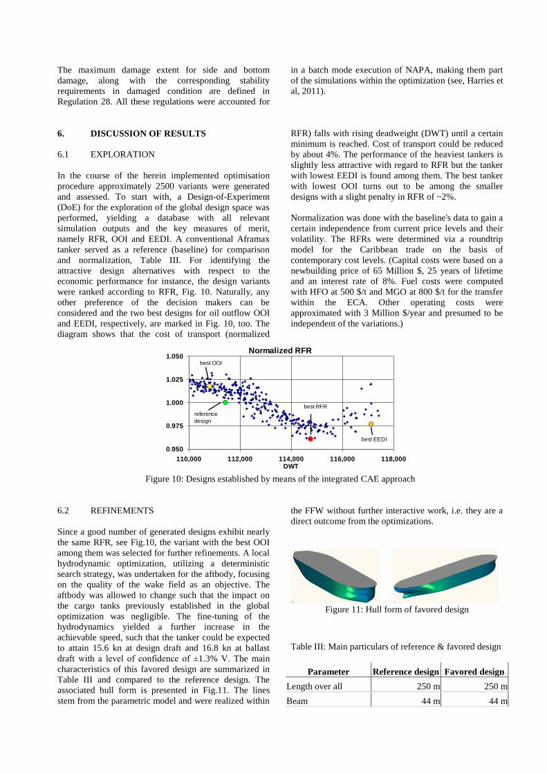
6.1 EXPLORATION
In the course of the herein implemented optimisation
procedure approximately 2500 variants were generated
and assessed. To start with, a Design-of-Experiment
(DoE) for the exploration of the global design space was
performed, yielding a database with all relevant
simulation outputs and the key measures of merit,
namely RFR, OOI and EEDI. A conventional Aframax
tanker served as a reference (baseline) for comparison
and normalization, Table III. For identifying the
attractive design alternatives with respect to the
economic performance for instance, the design variants
were ranked according to RFR, Fig. 10. Naturally, any
other preference of the decision makers can be
considered and the two best designs for oil outflow OOI
and EEDI, respectively, are marked in Fig. 10, too. The
diagram shows that the cost of transport (normalized
RFR) falls with rising deadweight (DWT) until a certain
minimum is reached. Cost of transport could be reduced
by about 4%. The performance of the heaviest tankers is
slightly less attractive with regard to RFR but the tanker
with lowest EEDI is found among them. The best tanker
with lowest OOI turns out to be among the smaller
designs with a slight penalty in RFR of ~2%.
Normalization was done with the baseline's data to gain a
certain independence from current price levels and their
volatility. The RFRs were determined via a roundtrip
model for the Caribbean trade on the basis of
contemporary cost levels. (Capital costs were based on a
newbuilding price of 65 Million $, 25 years of lifetime
and an interest rate of 8%. Fuel costs were computed
with HFO at 500 $/t and MGO at 800 $/t for the transfer
within the ECA. Other operating costs were
approximated with 3 Million $/year and presumed to be
independent of the variations.)
Normalized RFR
0.950
0.975
1.000
1.025
1.050
110,000 112,000 114,000 116,000 118,000DWT
best EEDI
best OOI
best RFR
reference
design
Figure 10: Designs established by means of the integrated CAE approach
6.2 REFINEMENTS
Since a good number of generated designs exhibit nearly
the same RFR, see Fig.10, the variant with the best OOI
among them was selected for further refinements. A local
hydrodynamic optimization, utilizing a deterministic
search strategy, was undertaken for the aftbody, focusing
on the quality of the wake field as an objective. The
aftbody was allowed to change such that the impact on
the cargo tanks previously established in the global
optimization was negligible. The fine-tuning of the
hydrodynamics yielded a further increase in the
achievable speed, such that the tanker could be expected
to attain 15.6 kn at design draft and 16.8 kn at ballast
draft with a level of confidence of ±1.3% V. The main
characteristics of this favored design are summarized in
Table III and compared to the reference design. The
associated hull form is presented in Fig.11. The lines
stem from the parametric model and were realized within
the FFW without further interactive work, i.e. they are a
direct outcome from the optimizations.
Figure 11: Hull form of favored design
Table III: Main particulars of reference & favored design
Parameter Reference design Favored design
Length over all 250 m 250 m
Beam 44 m 44 m
Depth 21.0 m 21.5 m
Design draft 13.7 m 13.7 m
Block coefficient 0.83 0.85
Inner bottom height
COT 2-6 (S+P) 2.50 m 2.10 m
Inner bottom height
COT 1 (S+P) 2.50 m 2.75 m
Side shell width 2.50 m 2.65 m
Angle of hopper plate 50° 37°
Width of hopper plate 5.25 m 5.20 m
Frame spacing 3.780 m 4.400 m
Shift of bulkheads 0 m 0 m
DWT 111 436 t 114 923 t
Maximum cargo
volume 124 230 m3 129 644 m
3
OOI 0.0138 0.0142
Speed at design draft 15.1 kn 15.6 kn
Speed at ballast draft 15.9 kn 16.8 kn
EEDI
3.541 g CO2 /
(t nm)
3.281 g CO2 /
(t nm)
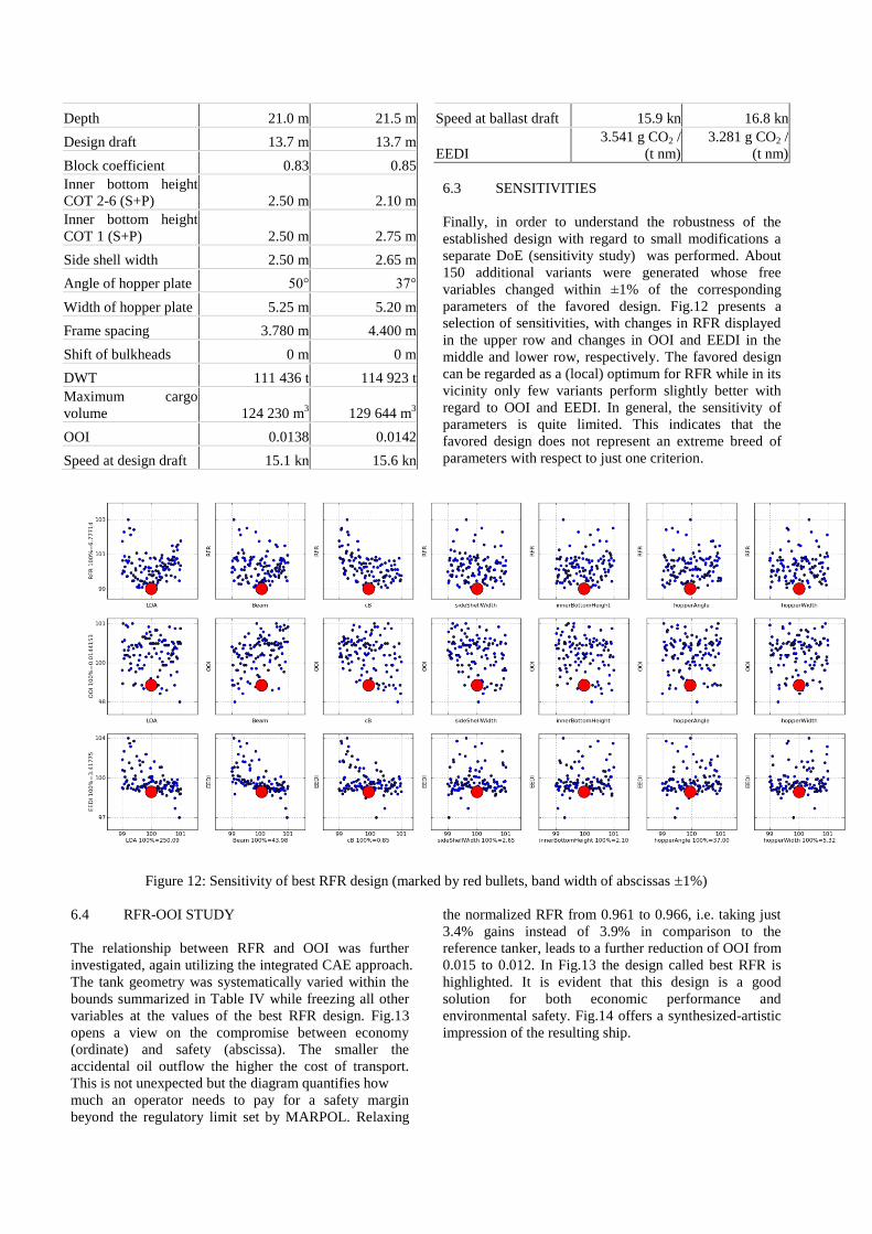
6.3 SENSITIVITIES
Finally, in order to understand the robustness of the
established design with regard to small modifications a
separate DoE (sensitivity study) was performed. About
150 additional variants were generated whose free
variables changed within ±1% of the corresponding
parameters of the favored design. Fig.12 presents a
selection of sensitivities, with changes in RFR displayed
in the upper row and changes in OOI and EEDI in the
middle and lower row, respectively. The favored design
can be regarded as a (local) optimum for RFR while in its
vicinity only few variants perform slightly better with
regard to OOI and EEDI. In general, the sensitivity of
parameters is quite limited. This indicates that the
favored design does not represent an extreme breed of
parameters with respect to just one criterion.
Figure 12: Sensitivity of best RFR design (marked by red bullets, band width of abscissas 1%)
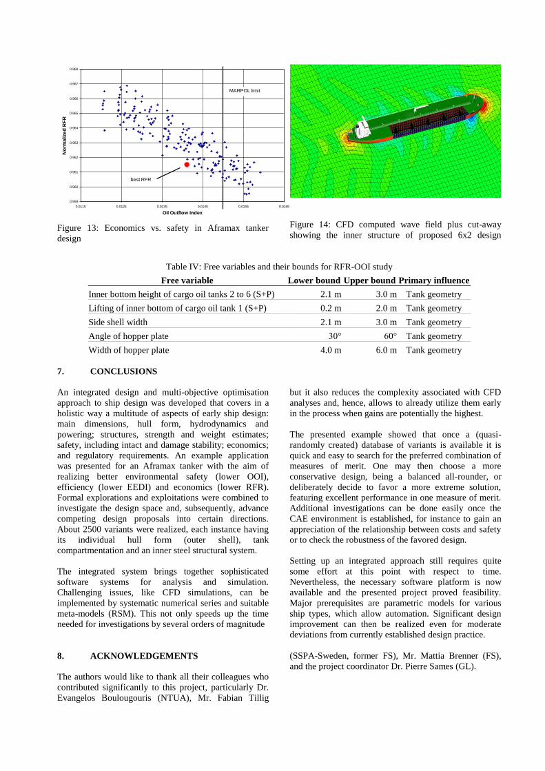
6.4 RFR-OOI STUDY
The relationship between RFR and OOI was further
investigated, again utilizing the integrated CAE approach.
The tank geometry was systematically varied within the
bounds summarized in Table IV while freezing all other
variables at the values of the best RFR design. Fig.13
opens a view on the compromise between economy
(ordinate) and safety (abscissa). The smaller the
accidental oil outflow the higher the cost of transport.
This is not unexpected but the diagram quantifies how
much an operator needs to pay for a safety margin
beyond the regulatory limit set by MARPOL. Relaxing
the normalized RFR from 0.961 to 0.966, i.e. taking just
3.4% gains instead of 3.9% in comparison to the
reference tanker, leads to a further reduction of OOI from
0.015 to 0.012. In Fig.13 the design called best RFR is
highlighted. It is evident that this design is a good
solution for both economic performance and
environmental safety. Fig.14 offers a synthesized-artistic
impression of the resulting ship.
0.959
0.960
0.961
0.962
0.963
0.964
0.965
0.966
0.967
0.968
0.0115 0.0125 0.0135 0.0145 0.0155 0.0165
Oil Outflow Index
No
rma
lize
d R
FR
best RFR
MARPOL limit
Figure 13: Economics vs. safety in Aframax tanker
design
Figure 14: CFD computed wave field plus cut-away
showing the inner structure of proposed 6x2 design
Table IV: Free variables and their bounds for RFR-OOI study
Free variable Lower bound Upper bound Primary influence
Inner bottom height of cargo oil tanks 2 to 6 (S+P) 2.1 m 3.0 m Tank geometry
Lifting of inner bottom of cargo oil tank 1 (S+P) 0.2 m 2.0 m Tank geometry
Side shell width 2.1 m 3.0 m Tank geometry
Angle of hopper plate 30° 60° Tank geometry
Width of hopper plate 4.0 m 6.0 m Tank geometry
7. CONCLUSIONS
An integrated design and multi-objective optimisation
approach to ship design was developed that covers in a
holistic way a multitude of aspects of early ship design:
main dimensions, hull form, hydrodynamics and
powering; structures, strength and weight estimates;
safety, including intact and damage stability; economics;
and regulatory requirements. An example application
was presented for an Aframax tanker with the aim of
realizing better environmental safety (lower OOI),
efficiency (lower EEDI) and economics (lower RFR).
Formal explorations and exploitations were combined to
investigate the design space and, subsequently, advance
competing design proposals into certain directions.
About 2500 variants were realized, each instance having
its individual hull form (outer shell), tank
compartmentation and an inner steel structural system.
The integrated system brings together sophisticated
software systems for analysis and simulation.
Challenging issues, like CFD simulations, can be
implemented by systematic numerical series and suitable
meta-models (RSM). This not only speeds up the time
needed for investigations by several orders of magnitude
but it also reduces the complexity associated with CFD
analyses and, hence, allows to already utilize them early
in the process when gains are potentially the highest.
The presented example showed that once a (quasi-
randomly created) database of variants is available it is
quick and easy to search for the preferred combination of
measures of merit. One may then choose a more
conservative design, being a balanced all-rounder, or
deliberately decide to favor a more extreme solution,
featuring excellent performance in one measure of merit.
Additional investigations can be done easily once the
CAE environment is established, for instance to gain an
appreciation of the relationship between costs and safety
or to check the robustness of the favored design.
Setting up an integrated approach still requires quite
some effort at this point with respect to time.
Nevertheless, the necessary software platform is now
available and the presented project proved feasibility.
Major prerequisites are parametric models for various
ship types, which allow automation. Significant design
improvement can then be realized even for moderate
deviations from currently established design practice.
8. ACKNOWLEDGEMENTS
The authors would like to thank all their colleagues who
contributed significantly to this project, particularly Dr.
Evangelos Boulougouris (NTUA), Mr. Fabian Tillig
(SSPA-Sweden, former FS), Mr. Mattia Brenner (FS),
and the project coordinator Dr. Pierre Sames (GL).

9. REFERENCES
1. ABT, C.; HARRIES, S., ‘A New Approach to
Integration of CAD and CFD for Naval Architects’,
6th COMPIT, Cortona, 2007.
2. ABT, C.; HARRIES, S., ‘Hull Variation and
Improvement Using the Generalised Lackenby
Method of the FRIENDSHIP-FRAMEWORK’, The
Naval Architect, September, 2007.
3. ABT, C.; HARRIES, S.; WUNDERLICH, S.;
ZEITZ, B., ‘Flexible Tool Integration For
Simulation-driven Design Using XML, Generic and
COM interfaces’, 8th COMPIT, Budapest, 2009.
4. BRENNER, M.; ABT, C.; Harries, S., ‘Feature
Modelling and Simulation-driven Design For Faster
Processes and Greener Products’, ICCAS, Shanghai,
2009.
5. FAHRBACH, M., ‘Bewertung der Güte von
Nachstromfeldern’, Diploma Thesis (in German),
TU Hamburg-Harburg, 2004.
6. HARRIES, S., ‘Investigating Multi-dimensional
Design Spaces Using First Principle Methods’, 7th
Int. Conf. High-Performance Marine Vehicles
(HIPER), Melbourne, 2010.
7. HARRIES, S.; ABT, C.; HEIMANN, J.;
HOCHKIRCH, K., ‘Advanced Hydrodynamic
Design of Container Carriers For Improved
Transport Efficiency’, RINA Conf. Design &
Operation of Container Ships, London, 2006.
8. HARRIES, S., TILLIG, F., WILKEN, M.,
ZARAPHONITIS, G., ‚An Integrated Approach to
Simulation in the Early Design of a Tanker‘,, Proc.
Int. Conf. on Computer and IT Applications in the
Maritime Industries, COMPIT 2011, Berlin, May
2011.
9. MEPC, ‘Resolution MEPC.110(49) - Revised
Interim Guidelines for the Approval of Alternative
Methods of Design and Construction of Oil Tankers
Under Regulation 13F(5) of Annex I of MARPOL
73/78’, MEPC, International Maritime Organization,
London, 2003.
10. MEPC, ‘Resolution MEPC.122(52) - Explanatory
Notes on Matters Related to the Accidental Oil
Outflow Performance Under Regulation 23 of the
Revised MARPOL Annex I’, MEPC International
Maritime Organization, London, 2004.
11. MEPC, ‘MEPC 58/17/2- Formal Safety Assessment
– Crude Oil Tanker’, MEPC, International Maritime
Organization, London, 2008.
12. MEPC, ‘MEPC.1/Circ.681 - Interim Guidelines on
the Method of Calculation of the Energy Efficiency
Design Index for New Ships’, MEPC, International
Maritime Organization, London, 2009.
13. PAPANIKOLAOU, A.; ZARAPHONITIS, G.;
BOULOUGOURIS, E.; LANGBECKER, U.;
MATHO, S.; SAMES, P., ‘Optimization of an
AFRAMAX Oil Tanker Design, J. Marine Science
and Technology, 2010.
14. PAPANIKOLAOU, A.; ‘Holistic Ship Design
Optimization’. Journal Computer-Aided Design,
Elsevier, Vol. 42, Issue 11, pp. 1028-1044, 2010.
15. SAMES, P.; PAPANIKOLAOU, A.; HARRIES, S.;
COYNE, P., ‘BEST – Better Economics with Safer
Tankers’, Proc. RINA Int. Conf. on Design and
Operation of Tankers, Athens, 8-9 June 2011.
16. TILLIG, F., ‘Parametric Modeling and
Hydrodynamic Analysis of Twin-Skeg Vessels’,
Diploma thesis, TU Berlin, 2010.
8. AUTHORS’ BIOGRAPHIES
Apostolos Papanikolaou is Professor and Director of the
Ship Design Laboratory of the National Technical
University of Athens (http://www.naval.ntua.gr/sdl). His
educational, research and professional activities cover a
broad area of Naval Architecture and Ocean Engineering.
He was and is Principal Investigator of a large variety of
funded research work regarding the design and
optimization of conventional and unconventional vessels,
the hydrodynamic analysis and assessment of ship’s calm
water performance , the performance of ships in seaways,
the logistics-based ship design, the risk-based design, the
intact and damage ship stability , the Formal Safety
Assessment of ships and related regulatory developments
of the International Maritime Organization (IMO),
Marine accidents investigations, the multi-objective
optimization problems and numerical simulation
techniques.
Stefan Harries is Managing Director of FRIENDSHIP
SYSTEMS GmbH (http://www.friendship-systems.com).
He is responsible for research and development regarding
simulation-driven design on the basis of the CAD-CFD
integration platform FRIENDSHIP-Framework. His
experience comprises parametric modelling, formal
optimization and hydrodynamic simulation. He founded
FRIENDSHIP SYSTEMS in 2001 after studying in
Germany and the USA and receiving his PhD in naval
architecture from TU Berlin.
Marc Wilken works as senior project manager at the
research and development department of the
Germanischer Lloyd SE, at Hamburg in Germany
(http://www.gl-group.com). His previous experience
includes the development of finite element modelling
tools and numerical procedures for strength assessment
of ships.
George Zaraphonitis is Associate Professor at the
National Technical University of Athens and senior
member of the Ship Design Laboratory-NTUA. His
previous experience includes in depth research in the
design and optimization of conventional and
unconventional vessels and the hydrodynamic analysis
and assessment of ship’s performance in seaways, the
intact and damage ship stability.