
Instrument Control Toolbox
434
Computation Visualization Programming For Use with MATLAB ® User’s Guide Version 1 Instrument Control Toolbox
Transcript of Instrument Control Toolbox
Computation
Visualization
Programming
For Use with MATLAB®
User’s GuideVersion 1
Instrument ControlToolbox
How to Contact The MathWorks:
www.mathworks.com Webcomp.soft-sys.matlab Newsgroup
[email protected] Technical [email protected] Product enhancement [email protected] Bug [email protected] Documentation error [email protected] Order status, license renewals, [email protected] Sales, pricing, and general information
508-647-7000 Phone
508-647-7001 Fax
The MathWorks, Inc. Mail3 Apple Hill DriveNatick, MA 01760-2098
For contact information about worldwide offices, see the MathWorks Web site.
Instrument Control Toolbox User’s Guide COPYRIGHT 2000 - 2002 by The MathWorks, Inc. The software described in this document is furnished under a license agreement. The software may be used or copied only under the terms of the license agreement. No part of this manual may be photocopied or repro-duced in any form without prior written consent from The MathWorks, Inc.
FEDERAL ACQUISITION: This provision applies to all acquisitions of the Program and Documentation by or for the federal government of the United States. By accepting delivery of the Program, the government hereby agrees that this software qualifies as "commercial" computer software within the meaning of FAR Part 12.212, DFARS Part 227.7202-1, DFARS Part 227.7202-3, DFARS Part 252.227-7013, and DFARS Part 252.227-7014. The terms and conditions of The MathWorks, Inc. Software License Agreement shall pertain to the government’s use and disclosure of the Program and Documentation, and shall supersede any conflicting contractual terms or conditions. If this license fails to meet the government’s minimum needs or is inconsistent in any respect with federal procurement law, the government agrees to return the Program and Documentation, unused, to MathWorks.
MATLAB, Simulink, Stateflow, Handle Graphics, and Real-Time Workshop are registered trademarks, and TargetBox is a trademark of The MathWorks, Inc.
Other product or brand names are trademarks or registered trademarks of their respective holders.
Printing History: November 2000 First printing New for Version 1 (Release 12)June 2001 Second printing Revised for Version 1.1 (Release 12.1)July 2002 Online only Revised for Version 1.2 (Release 13)

i
Contents
Preface
What Is the Instrument Control Toolbox? . . . . . . . . . . . . . . . . . xExploring the Toolbox . . . . . . . . . . . . . . . . . . . . . . . . . . . . . . . . . . . x
Related Products . . . . . . . . . . . . . . . . . . . . . . . . . . . . . . . . . . . . . . xi
Using This Guide . . . . . . . . . . . . . . . . . . . . . . . . . . . . . . . . . . . . . . xiiExpected Background . . . . . . . . . . . . . . . . . . . . . . . . . . . . . . . . . . xiiLearning the Instrument Control Toolbox . . . . . . . . . . . . . . . . . . xiiHow This Guide Is Organized . . . . . . . . . . . . . . . . . . . . . . . . . . . xiii
Installation Information . . . . . . . . . . . . . . . . . . . . . . . . . . . . . . . xivToolbox Installation . . . . . . . . . . . . . . . . . . . . . . . . . . . . . . . . . . . xivHardware and Driver Installation . . . . . . . . . . . . . . . . . . . . . . . xiv
Typographical Conventions . . . . . . . . . . . . . . . . . . . . . . . . . . . . xv
1
Getting Started with the InstrumentControl Toolbox
Toolbox Components . . . . . . . . . . . . . . . . . . . . . . . . . . . . . . . . . . 1-2M-File Functions . . . . . . . . . . . . . . . . . . . . . . . . . . . . . . . . . . . . . 1-3The Interface Driver Adaptor . . . . . . . . . . . . . . . . . . . . . . . . . . . 1-4
Communicating with Your Instrument . . . . . . . . . . . . . . . . . 1-5Communicating with a GPIB Instrument . . . . . . . . . . . . . . . . . 1-5Communicating with a GPIB-VXI Instrument . . . . . . . . . . . . . 1-6Communicating with a Serial Port Instrument . . . . . . . . . . . . . 1-7
Understanding the Toolbox Capabilities . . . . . . . . . . . . . . . . 1-9The Contents M-File . . . . . . . . . . . . . . . . . . . . . . . . . . . . . . . . . . 1-9
ii Contents
Documentation Examples . . . . . . . . . . . . . . . . . . . . . . . . . . . . . . 1-9Demos . . . . . . . . . . . . . . . . . . . . . . . . . . . . . . . . . . . . . . . . . . . . . . 1-9
Examining Your Hardware Resources . . . . . . . . . . . . . . . . . 1-13General Toolbox Information . . . . . . . . . . . . . . . . . . . . . . . . . . 1-13Interface Information . . . . . . . . . . . . . . . . . . . . . . . . . . . . . . . . . 1-13Adaptor Information . . . . . . . . . . . . . . . . . . . . . . . . . . . . . . . . . 1-14Instrument Object Information . . . . . . . . . . . . . . . . . . . . . . . . . 1-16
Getting Help . . . . . . . . . . . . . . . . . . . . . . . . . . . . . . . . . . . . . . . . . 1-17The instrhelp Function . . . . . . . . . . . . . . . . . . . . . . . . . . . . . . . 1-17The propinfo Function . . . . . . . . . . . . . . . . . . . . . . . . . . . . . . . . 1-18
2The Instrument Control Session
Creating an Instrument Object . . . . . . . . . . . . . . . . . . . . . . . . . 2-2Configuring Properties During Object Creation . . . . . . . . . . . . 2-3Creating an Array of Instrument Objects . . . . . . . . . . . . . . . . . . 2-3
Connecting to the Instrument . . . . . . . . . . . . . . . . . . . . . . . . . . 2-5
Configuring and Returning Properties . . . . . . . . . . . . . . . . . . 2-6Returning Property Names and Property Values . . . . . . . . . . . 2-6Configuring Property Values . . . . . . . . . . . . . . . . . . . . . . . . . . . . 2-9Specifying Property Names . . . . . . . . . . . . . . . . . . . . . . . . . . . . . 2-9Default Property Values . . . . . . . . . . . . . . . . . . . . . . . . . . . . . . 2-10The Property Inspector . . . . . . . . . . . . . . . . . . . . . . . . . . . . . . . 2-10
Writing and Reading Data . . . . . . . . . . . . . . . . . . . . . . . . . . . . 2-12Writing Data . . . . . . . . . . . . . . . . . . . . . . . . . . . . . . . . . . . . . . . 2-13Reading Data . . . . . . . . . . . . . . . . . . . . . . . . . . . . . . . . . . . . . . . 2-19
Disconnecting and Cleaning Up . . . . . . . . . . . . . . . . . . . . . . . 2-25Disconnecting an Instrument Object . . . . . . . . . . . . . . . . . . . . 2-25Cleaning Up the MATLAB Environment . . . . . . . . . . . . . . . . . 2-25

iii
3Controlling GPIB Instruments
GPIB Overview . . . . . . . . . . . . . . . . . . . . . . . . . . . . . . . . . . . . . . . 3-2What Is GPIB? . . . . . . . . . . . . . . . . . . . . . . . . . . . . . . . . . . . . . . . 3-2Important GPIB Features . . . . . . . . . . . . . . . . . . . . . . . . . . . . . . 3-3GPIB Lines . . . . . . . . . . . . . . . . . . . . . . . . . . . . . . . . . . . . . . . . . . 3-4Status and Event Reporting . . . . . . . . . . . . . . . . . . . . . . . . . . . . 3-9Using Vendor Tools to Identify and Test Your Resources . . . . 3-14
Creating a GPIB Object . . . . . . . . . . . . . . . . . . . . . . . . . . . . . . . 3-18The GPIB Object Display . . . . . . . . . . . . . . . . . . . . . . . . . . . . . . 3-19
Configuring the GPIB Address . . . . . . . . . . . . . . . . . . . . . . . . 3-20
Writing and Reading Data . . . . . . . . . . . . . . . . . . . . . . . . . . . . 3-21Rules for Completing Write and Read Operations . . . . . . . . . . 3-21Example: Writing and Reading Text Data . . . . . . . . . . . . . . . . 3-22Example: Reading Binary Data . . . . . . . . . . . . . . . . . . . . . . . . . 3-24Example: Parsing Input Data Using scanstr . . . . . . . . . . . . . . 3-26Example: Understanding EOI and EOS . . . . . . . . . . . . . . . . . . 3-27
Events and Callbacks . . . . . . . . . . . . . . . . . . . . . . . . . . . . . . . . . 3-30Example: Introduction to Events and Callbacks . . . . . . . . . . . 3-30Event Types and Callback Properties . . . . . . . . . . . . . . . . . . . . 3-31Storing Event Information . . . . . . . . . . . . . . . . . . . . . . . . . . . . 3-32Creating and Executing Callback Functions . . . . . . . . . . . . . . 3-33Enabling Callback Functions After They Error . . . . . . . . . . . . 3-34Example: Using Events and Callbacks to Read Binary Data . 3-35
Triggers . . . . . . . . . . . . . . . . . . . . . . . . . . . . . . . . . . . . . . . . . . . . . 3-37Example: Executing a Trigger . . . . . . . . . . . . . . . . . . . . . . . . . . 3-37
Serial Polls . . . . . . . . . . . . . . . . . . . . . . . . . . . . . . . . . . . . . . . . . . 3-39Example: Executing a Serial Poll . . . . . . . . . . . . . . . . . . . . . . . 3-39
iv Contents
4
Controlling Instruments Using theVISA Standard
VISA Overview . . . . . . . . . . . . . . . . . . . . . . . . . . . . . . . . . . . . . . . . 4-2Using Vendor Tools to Identify and Test Your Resources . . . . . 4-3
The GPIB Interface . . . . . . . . . . . . . . . . . . . . . . . . . . . . . . . . . . . 4-5Creating a VISA-GPIB Object . . . . . . . . . . . . . . . . . . . . . . . . . . . 4-5The VISA-GPIB Address . . . . . . . . . . . . . . . . . . . . . . . . . . . . . . . 4-7
The VXI Interface . . . . . . . . . . . . . . . . . . . . . . . . . . . . . . . . . . . . . 4-9Creating a VISA-VXI Object . . . . . . . . . . . . . . . . . . . . . . . . . . . 4-10The VISA-VXI Address . . . . . . . . . . . . . . . . . . . . . . . . . . . . . . . 4-12Register-Based Communication . . . . . . . . . . . . . . . . . . . . . . . . 4-13
The GPIB-VXI Interface . . . . . . . . . . . . . . . . . . . . . . . . . . . . . . 4-21Creating a VISA-GPIB-VXI Object . . . . . . . . . . . . . . . . . . . . . . 4-22The VISA-GPIB-VXI Address . . . . . . . . . . . . . . . . . . . . . . . . . . 4-24
The Serial Port Interface . . . . . . . . . . . . . . . . . . . . . . . . . . . . . 4-26Creating a VISA-Serial Object . . . . . . . . . . . . . . . . . . . . . . . . . 4-26Configuring Communication Settings . . . . . . . . . . . . . . . . . . . 4-28
5Controlling Serial Port Instruments
Serial Port Overview . . . . . . . . . . . . . . . . . . . . . . . . . . . . . . . . . . 5-2What Is Serial Communication? . . . . . . . . . . . . . . . . . . . . . . . . . 5-2The Serial Port Interface Standard . . . . . . . . . . . . . . . . . . . . . . 5-2Connecting Two Devices with a Serial Cable . . . . . . . . . . . . . . . 5-3Serial Port Signals and Pin Assignments . . . . . . . . . . . . . . . . . . 5-5Serial Data Format . . . . . . . . . . . . . . . . . . . . . . . . . . . . . . . . . . . 5-9Finding Serial Port Information for Your Platform . . . . . . . . . 5-13
Creating a Serial Port Object . . . . . . . . . . . . . . . . . . . . . . . . . 5-16The Serial Port Object Display . . . . . . . . . . . . . . . . . . . . . . . . . 5-17
v
Configuring Communication Settings . . . . . . . . . . . . . . . . . . 5-18
Writing and Reading Data . . . . . . . . . . . . . . . . . . . . . . . . . . . . 5-19Asynchronous Write and Read Operations . . . . . . . . . . . . . . . . 5-19Rules for Completing Write and Read Operations . . . . . . . . . . 5-20Example: Writing and Reading Text Data . . . . . . . . . . . . . . . . 5-21
Events and Callbacks . . . . . . . . . . . . . . . . . . . . . . . . . . . . . . . . . 5-24Event Types and Callback Properties . . . . . . . . . . . . . . . . . . . . 5-24Storing Event Information . . . . . . . . . . . . . . . . . . . . . . . . . . . . 5-25Example: Using Events and Callbacks . . . . . . . . . . . . . . . . . . . 5-27
Using Control Pins . . . . . . . . . . . . . . . . . . . . . . . . . . . . . . . . . . . 5-29Signaling the Presence of Connected Devices . . . . . . . . . . . . . 5-29Controlling the Flow of Data: Handshaking . . . . . . . . . . . . . . 5-32
6Controlling Instruments Using TCP/IP and UDP
TCP/IP and UDP Overview . . . . . . . . . . . . . . . . . . . . . . . . . . . . . 6-2
Creating a TCP/IP Object . . . . . . . . . . . . . . . . . . . . . . . . . . . . . . 6-4The TCP/IP Object Display . . . . . . . . . . . . . . . . . . . . . . . . . . . . . 6-5Example: Server Drops the Connection . . . . . . . . . . . . . . . . . . . 6-6
Creating a UDP Object . . . . . . . . . . . . . . . . . . . . . . . . . . . . . . . . 6-8The UDP Object Display . . . . . . . . . . . . . . . . . . . . . . . . . . . . . . . 6-9Example: Communicating Between Two Hosts . . . . . . . . . . . . 6-10
Writing and Reading Data . . . . . . . . . . . . . . . . . . . . . . . . . . . . 6-12Rules for Completing Write and Read Operations . . . . . . . . . . 6-12Example: Writing and Reading Data with a TCP/IP Object . . 6-13Example: Writing and Reading Data with a UDP Object . . . . 6-17
Events and Callbacks . . . . . . . . . . . . . . . . . . . . . . . . . . . . . . . . . 6-19
vi Contents
Event Types and Callback Properties . . . . . . . . . . . . . . . . . . . . 6-19Storing Event Information . . . . . . . . . . . . . . . . . . . . . . . . . . . . 6-20Example: Using Events and Callbacks . . . . . . . . . . . . . . . . . . . 6-21
7Saving and Loading the Session
Saving and Loading Instrument Objects . . . . . . . . . . . . . . . . 7-2Saving Instrument Objects to an M-File . . . . . . . . . . . . . . . . . . 7-2Saving Objects to a MAT-File . . . . . . . . . . . . . . . . . . . . . . . . . . . 7-4
Debugging: Recording Information to Disk . . . . . . . . . . . . . . 7-5Example: Introduction to Recording Information . . . . . . . . . . . 7-5Creating Multiple Record Files . . . . . . . . . . . . . . . . . . . . . . . . . . 7-6Specifying a Filename . . . . . . . . . . . . . . . . . . . . . . . . . . . . . . . . . 7-6The Record File Format . . . . . . . . . . . . . . . . . . . . . . . . . . . . . . . . 7-7Example: Recording Information to Disk . . . . . . . . . . . . . . . . . . 7-9
8Function Reference
Functions – By Category . . . . . . . . . . . . . . . . . . . . . . . . . . . . . . . 8-2Base Functions . . . . . . . . . . . . . . . . . . . . . . . . . . . . . . . . . . . . . . . 8-2Object-Specific Functions . . . . . . . . . . . . . . . . . . . . . . . . . . . . . . 8-4
Functions – Alphabetical List . . . . . . . . . . . . . . . . . . . . . . . . . . 8-7
9Property Reference
Properties – By Category . . . . . . . . . . . . . . . . . . . . . . . . . . . . . . 9-2Base Properties . . . . . . . . . . . . . . . . . . . . . . . . . . . . . . . . . . . . . . 9-2
vii
Object-Specific Properties . . . . . . . . . . . . . . . . . . . . . . . . . . . . . . 9-4
Properties – Alphabetical List . . . . . . . . . . . . . . . . . . . . . . . . . 9-10
ASelected Bibliography
Index

viii Contents
Preface
This chapter provides a brief overview of the Instrument Control Toolbox, as well as information about this documentation set. The sections are as follows.
What Is the Instrument Control Toolbox? (p. x)
The toolbox and the kinds of tasks it can perform
Related Products (p. xi) MathWorks products related to this toolbox
Using This Guide (p. xii) An overview of this guide
Installation Information (p. xiv)
How to determine whether the toolbox is installed on your system
Typographical Conventions (p. xv)
Typographical conventions that this guide uses
x
What Is the Instrument Control Toolbox?The Instrument Control Toolbox is a collection of M-file functions built on the MATLAB® technical computing environment. The toolbox provides you with these features:
• A framework for communicating with instruments that support the GPIB interface (IEEE-488), the VISA standard, the TCP/IP or UDP protocols, and the serial port interface (RS-232, RS-422, and RS-485). Note that the toolbox extends the basic serial port features included with MATLAB.
• Functions for transferring data between MATLAB and your instrument:
- The data can be binary (numerical) or text.
- Text data can be any command used by your instrument such as a command given by the Standard Commands for Programmable Instruments (SCPI) language.
- The transfer can be synchronous and block the MATLAB command line, or asynchronous and not block the MATLAB command line.
• Event-based communication
• Functions for recording data and event information to a text file
• Tools that facilitate instrument control in an easy-to-use graphical environment
Exploring the ToolboxA list of the toolbox functions is available to you by typing
help instrument
You can view the code for any function by typing
type function_name
You can view the help for any function by typing
instrhelp function_name
You can change the way any toolbox function works by copying and renaming the M-file, then modifying your copy. You can also extend the toolbox by adding your own M-files, or by using it in combination with other products such as the MATLAB Report Generator or the Data Acquisition Toolbox.
Related Products
xi
Related ProductsThe MathWorks provides several related products that are especially relevant to the kinds of tasks you can perform with the Instrument Control Toolbox. For more information about any of these products, see either
• The online documentation for that product if it is installed or if you are reading the documentation from the CD
• The MathWorks Web site, at http://www.mathworks.com; see the “products” section
The toolboxes listed below all include functions that extend the capabilities of MATLAB.
Product Description
Data Acquisition Toolbox Acquire and send out data from plug-in data acquisition boards
Database Toolbox Exchange data with relational databases
MATLAB Report Generator
Automatically generate documentation for MATLAB applications and data
Signal Processing Toolbox
Perform signal processing, analysis, and algorithm development
Statistics Toolbox Apply statistical algorithms and probability models
System Identification Toolbox
Create linear dynamic models from measured input-output data
Wavelet Toolbox Analyze, compress, and denoise signals and images using wavelet techniques
xii
Using This Guide
Expected BackgroundTo use the Instrument Control Toolbox, you should have some familiarity with
• The basic features of MATLAB
• The commands used to communicate with your instrument; these commands might use the SCPI language or some other vendor-specific language
• The features of the interface associated with your instrument
Learning the Instrument Control ToolboxStart with Chapter 1, “Getting Started with the Instrument Control Toolbox,” which describes how to examine your hardware resources, how to communicate with your instrument, how to get online help, and so on. Then read Chapter 2, “The Instrument Control Session,” which provides a framework for constructing instrument control applications. Depending on the interface used by your instrument, you might then want to read the appropriate interface-specific chapter. These chapters are described in the next section.
If you want detailed information about a specific function, refer to Chapter 8, “Function Reference.” If you want detailed information about a specific property, refer to Chapter 9, “Property Reference.”
Using the Documentation Examples with Your InstrumentThe examples in this guide use specific peripheral instruments such as a Tektronix TDS 210 two-channel oscilloscope or an Agilent 33120A function generator. Additionally, the GPIB examples use a National Instruments GPIB controller and the serial port examples use the COM1 serial port. The string commands written to these instruments are often unique to the vendor, and the address information such as the board index or primary address associated with the hardware reflects a specific configuration.
If your instrument accepts different string commands, or if your hardware is configured to use different address information, then you should modify the examples accordingly.
Using This Guide
xiii
How This Guide Is OrganizedThe organization of this guide is described below.
Chapter Description
Getting Started Describes how to get started with the Instrument Control Toolbox. Topics include examining your hardware resources and communicating with your instrument.
The Instrument Control Session
Describes all the steps you are likely to take when communicating with your instrument.
Controlling GPIB Instruments
Shows you how to use the toolbox to communicate with instruments that support the GPIB interface.
Controlling Instruments Using the VISA Standard
Shows you how to use the toolbox to communicate with instruments that support the VISA standard.
Controlling Serial Port Instruments
Shows you how to use the toolbox to communicate with instruments that support the serial port interface.
Saving and Loading the Session
Shows you how to save your work to an M-file, a MAT-file, or a text file.
Function Reference Presents a complete description of all toolbox functions.
Property Reference Presents a complete description of all toolbox properties.
Selected Bibliography Presents a list of references for exploring instrumentation standards and hardware.
xiv
Installation InformationTo communicate with your instrument from the MATLAB environment, you must install these components:
• MATLAB 6.5 (Release 13)
• The Instrument Control Toolbox
Additionally, you might need to install hardware such as a GPIB controller and software such as drivers, support libraries, and so on. For a complete listing of all supported vendors, refer to “The Interface Driver Adaptor” on page 1-4.
Toolbox InstallationTo determine if the Instrument Control Toolbox is installed on your system, type
ver
at the MATLAB prompt. MATLAB displays information about the version of MATLAB you are running, including a list of installed add-on products and their version numbers. Check the list to see if the Instrument Control Toolbox appears.
For information about installing the toolbox, refer to the MATLAB Installation Guide for your platform. If you experience installation difficulties and have Web access, look for the installation and license information at the MathWorks Web site (http://www.mathworks.com/support).
Hardware and Driver InstallationInstallation of hardware devices such as GPIB controllers, instrument drivers, support libraries, and so on is described in the documentation provided by the instrument vendor. Many vendors provide the latest drivers through their Web site. For a list of vendor driver requirements and limitations, refer to the Instrument Control Toolbox Release Notes.
Note You must install all necessary device-specific software provided by the instrument vendor in addition to the Instrument Control Toolbox.
Typographical Conventions
xv
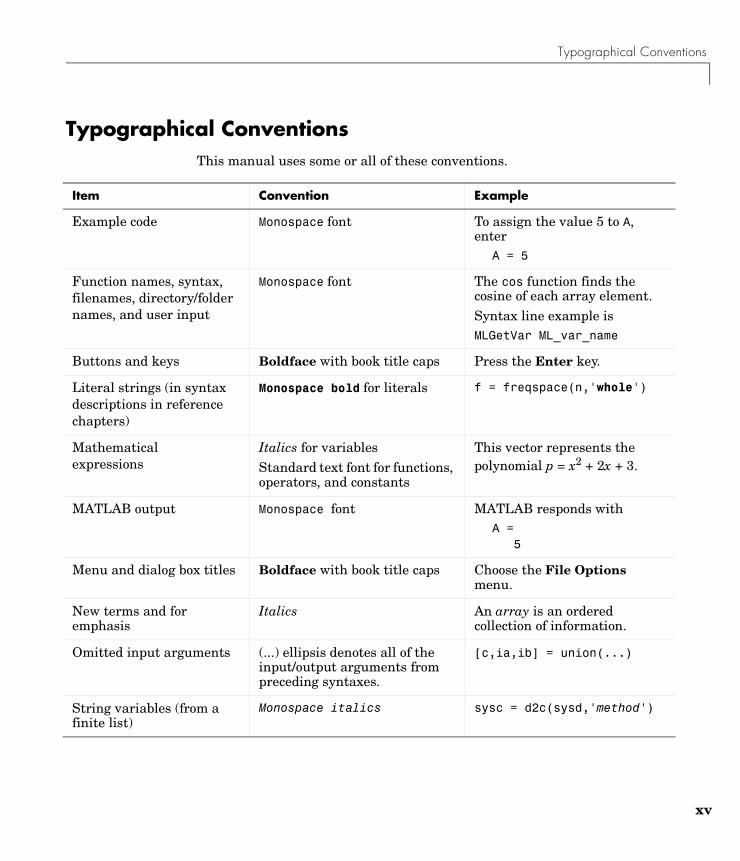
Typographical ConventionsThis manual uses some or all of these conventions.
Item Convention Example
Example code Monospace font To assign the value 5 to A, enter
A = 5
Function names, syntax, filenames, directory/folder names, and user input
Monospace font The cos function finds the cosine of each array element.Syntax line example isMLGetVar ML_var_name
Buttons and keys Boldface with book title caps Press the Enter key.
Literal strings (in syntax descriptions in reference chapters)
Monospace bold for literals f = freqspace(n,'whole')
Mathematicalexpressions
Italics for variablesStandard text font for functions, operators, and constants
This vector represents the polynomial p = x2 + 2x + 3.
MATLAB output Monospace font MATLAB responds withA =
5
Menu and dialog box titles Boldface with book title caps Choose the File Options menu.
New terms and for emphasis
Italics An array is an ordered collection of information.
Omitted input arguments (...) ellipsis denotes all of the input/output arguments from preceding syntaxes.
[c,ia,ib] = union(...)
String variables (from a finite list)
Monospace italics sysc = d2c(sysd,'method')

xvi

1Getting Started with the Instrument Control Toolbox
This chapter provides the information you need to get started with the Instrument Control Toolbox. The sections are as follows.
Toolbox Components (p. 1-2)
The M-files and interface driver adaptors that comprise the toolbox.
Communicating with Your Instrument (p. 1-5)
Examples that show you how to communicate with instruments that support the GPIB, GPIB-VXI, and serial port interfaces.
Understanding the Toolbox Capabilities (p. 1-9)
Resources to help you understand the toolbox capabilities including demos and documentation examples.
Examining Your Hardware Resources (p. 1-13)
Return hardware-related information visible to the toolbox including the installed adaptors and the syntax for creating instrument objects.
Getting Help (p. 1-17) Get help using the Help browser, M-file help, and other methods.

1 Getting Started with the Instrument Control Toolbox
1-2
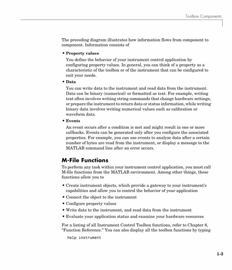
Toolbox ComponentsThe Instrument Control Toolbox consists of two distinct components: M-file functions and interface driver adaptors. These components allow you to pass information between MATLAB and your instrument. For example, the following diagram shows how information passes from MATLAB to an instrument via the GPIB driver and the GPIB controller.
Instrument Control Toolbox
GPIB driver
MATLAB
M-file functions
GPIB controller
Interface driver adaptors
Disk file
Interactive M-file functions
Property values, data, and events
Property values, data, and events
Toolbox Components
1-3
The preceding diagram illustrates how information flows from component to component. Information consists of
• Property values
You define the behavior of your instrument control application by configuring property values. In general, you can think of a property as a characteristic of the toolbox or of the instrument that can be configured to suit your needs.
• Data
You can write data to the instrument and read data from the instrument. Data can be binary (numerical) or formatted as text. For example, writing text often involves writing string commands that change hardware settings, or prepare the instrument to return data or status information, while writing binary data involves writing numerical values such as calibration or waveform data.
• Events
An event occurs after a condition is met and might result in one or more callbacks. Events can be generated only after you configure the associated properties. For example, you can use events to analyze data after a certain number of bytes are read from the instrument, or display a message to the MATLAB command line after an error occurs.
M-File FunctionsTo perform any task within your instrument control application, you must call M-file functions from the MATLAB environment. Among other things, these functions allow you to
• Create instrument objects, which provide a gateway to your instrument’s capabilities and allow you to control the behavior of your application
• Connect the object to the instrument
• Configure property values
• Write data to the instrument, and read data from the instrument
• Evaluate your application status and examine your hardware resources
For a listing of all Instrument Control Toolbox functions, refer to Chapter 8, “Function Reference.” You can also display all the toolbox functions by typing
help instrument
1 Getting Started with the Instrument Control Toolbox
1-4
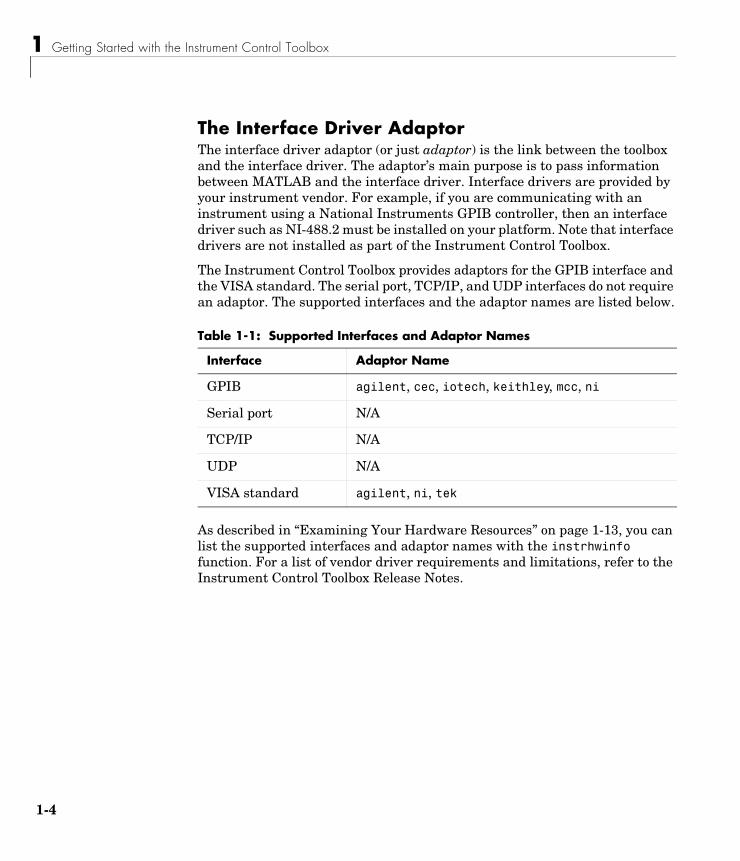
The Interface Driver AdaptorThe interface driver adaptor (or just adaptor) is the link between the toolbox and the interface driver. The adaptor’s main purpose is to pass information between MATLAB and the interface driver. Interface drivers are provided by your instrument vendor. For example, if you are communicating with an instrument using a National Instruments GPIB controller, then an interface driver such as NI-488.2 must be installed on your platform. Note that interface drivers are not installed as part of the Instrument Control Toolbox.
The Instrument Control Toolbox provides adaptors for the GPIB interface and the VISA standard. The serial port, TCP/IP, and UDP interfaces do not require an adaptor. The supported interfaces and the adaptor names are listed below.
As described in “Examining Your Hardware Resources” on page 1-13, you can list the supported interfaces and adaptor names with the instrhwinfo function. For a list of vendor driver requirements and limitations, refer to the Instrument Control Toolbox Release Notes.
Table 1-1: Supported Interfaces and Adaptor Names
Interface Adaptor Name
GPIB agilent, cec, iotech, keithley, mcc, ni
Serial port N/A
TCP/IP N/A
UDP N/A
VISA standard agilent, ni, tek
Communicating with Your Instrument
1-5
Communicating with Your InstrumentPerhaps the most effective way to get started with the Instrument Control Toolbox is to communicate with your instrument. This section provides simple examples that show you how to communicate with a
• GPIB instrument
• GPIB-VXI instrument
• Serial port instrument
Each example illustrates a typical instrument control session. The instrument control session comprises all the steps you are likely to take when communicating with a supported instrument. You should keep these steps in mind when constructing your own instrument control applications.
The examples also use specific instrument addresses, SCPI commands, and so on. If your instrument requires different parameters, or if it does not support the SCPI language, you should modify the examples accordingly.
If you want detailed information about any functions that are used, refer to Chapter 8, “Function Reference.” If you want detailed information about any properties that are used, refer to Chapter 9, “Property Reference.”
Communicating with a GPIB InstrumentThis example illustrates how to communicate with a GPIB instrument. The GPIB controller is a National Instruments AT-GPIB card. The instrument is an Agilent 33120A Function Generator, which is outputting a 2 volt peak-to-peak signal.
You should modify this example to suit your specific instrument control application needs. If you want detailed information about communicating with an instrument via GPIB, refer to Chapter 3, “Controlling GPIB Instruments.”
1 Create an instrument object — Create the GPIB object g associated with a National Instruments GPIB board with board index 0, and an instrument with primary address 1.
g = gpib('ni',0,1);
2 Connect to the instrument — Connect g to the instrument.
fopen(g)
1 Getting Started with the Instrument Control Toolbox
1-6
3 Configure property values — Configure g to assert the EOI line when the line feed character is written to the instrument, and to complete read operations when the line feed character is read from the instrument.
set(g,'EOSMode','read&write')set(g,'EOSCharCode','LF')
4 Write and read data — Change the instrument’s peak-to-peak voltage to 6 volts by writing the Volt 3 command, query the peak-to-peak voltage value, and then read the voltage value.
fprintf(g,'Volt 3')fprintf(g,'Volt?')data = fscanf(g)data =+3.00000E+00
5 Disconnect and clean up — When you no longer need g, you should disconnect it from the instrument, remove it from memory, and remove it from the MATLAB workspace.
fclose(g)delete(g)clear g
Communicating with a GPIB-VXI InstrumentThis example illustrates how to communicate with a VXI instrument via a GPIB controller using the VISA standard provided by Agilent Technologies.
The GPIB controller is an Agilent E1406A command module in VXI slot 0. The instrument is an Agilent E1441A Function/Arbitrary Waveform Generator in VXI slot 1, which is outputting a 2 volt peak-to-peak signal. The GPIB controller communicates with the instrument over the VXI backplane.
You should modify this example to suit your specific instrument control application needs. If you want detailed information about communicating with an instrument using the VISA standard, refer to Chapter 4, “Controlling Instruments Using the VISA Standard.”
Communicating with Your Instrument
1-7
1 Create an instrument object — Create the VISA-GPIB-VXI object v associated with the E1441A instrument located in chassis 0 with logical address 80.
v = visa('agilent','GPIB-VXI0::80::INSTR');
2 Connect to the instrument — Connect v to the instrument.
fopen(v)
3 Configure property values — Configure v to complete a read operation when the line feed character is read from the instrument.
set(v,'EOSMode','read')set(v,'EOSCharCode','LF')
4 Write and read data — Change the instrument’s peak-to-peak voltage to three volts by writing the Volt 3 command, query the peak-to-peak voltage value, and then read the voltage value.
fprintf(v,'Volt 3')fprintf(v,'Volt?')data = fscanf(v)data =+3.00000E+00
5 Disconnect and clean up — When you no longer need v, you should disconnect it from the instrument, remove it from memory, and remove it from the MATLAB workspace.
fclose(v)delete(v)clear v
Communicating with a Serial Port InstrumentThis example illustrates how to communicate with an instrument via the serial port. The instrument is a Tektronix TDS 210 two-channel digital oscilloscope connected to the COM1 port of a PC, and configured for a baud rate of 4800 and a carriage return (CR) terminator.
1 Getting Started with the Instrument Control Toolbox
1-8
You should modify this example to suit your specific instrument control application needs. If you want detailed information about communicating with an instrument connected to the serial port, refer to Chapter 5, “Controlling Serial Port Instruments.”
1 Create an instrument object — Create the serial port object s associated with the COM1 serial port.
s = serial('COM1');
2 Configure property values — Configure s to match the instrument’s baud rate and terminator.
set(s,'BaudRate',4800)set(s,'Terminator','CR')
3 Connect to the instrument — Connect s to the instrument. This step occurs after property values are configured because serial port instruments can transfer data immediately after the connection is established.
fopen(s)
4 Write and read data — Write the *IDN? command to the instrument and then read back the result of the command. *IDN? queries the instrument for identification information.
fprintf(s,'*IDN?')out = fscanf(s)out =TEKTRONIX,TDS 210,0,CF:91.1CT FV:v1.16 TDS2CM:CMV:v1.04
5 Disconnect and clean up — When you no longer need s, you should disconnect it from the instrument, remove it from memory, and remove it from the MATLAB workspace.
fclose(s)delete(s)clear s
Understanding the Toolbox Capabilities
1-9
Understanding the Toolbox CapabilitiesIn addition to the printed and online documentation, the Instrument Control Toolbox provides these resources to help you understand the product capabilities:
• The Contents M-file
• Documentation examples
• Demos
The Contents M-FileThe Contents M-file lists the toolbox functions and demos. You can display this information by typing
help instrument
Documentation ExamplesThis guide provides detailed examples that show you how to communicate with all supported interface types. These examples are collected in the example index, which is available through the Help browser.
The examples use specific peripheral instruments, GPIB controllers, string commands, address information, and so on. If your instrument accepts different string commands, or if your hardware is configured to use different address information, then you should modify the examples accordingly.
DemosThe toolbox includes a large collection of demos, which are divided into two main groups: command line tutorials and graphical applications. You can access all demos through the Help browser’s Demos pane. Use the following command to open the Help browser to the toolbox demos.
demo toolbox 'Instrument Control'
For your convenience, the command line tutorials are collected together using a graphical user interface (GUI). To open this GUI directly from the command line, type
instrschool
1 Getting Started with the Instrument Control Toolbox
1-10
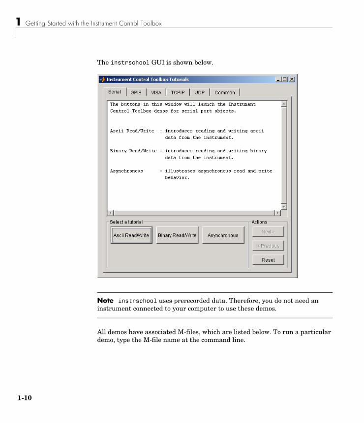
The instrschool GUI is shown below.
Note instrschool uses prerecorded data. Therefore, you do not need an instrument connected to your computer to use these demos.
All demos have associated M-files, which are listed below. To run a particular demo, type the M-file name at the command line.
Understanding the Toolbox Capabilities
1-11
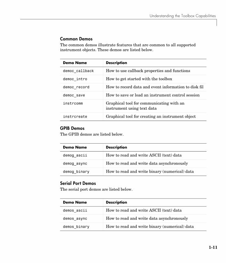
Common DemosThe common demos illustrate features that are common to all supported instrument objects. These demos are listed below.
GPIB DemosThe GPIB demos are listed below.
Serial Port DemosThe serial port demos are listed below.
Demo Name Description
democ_callback How to use callback properties and functions
democ_intro How to get started with the toolbox
democ_record How to record data and event information to disk fil
democ_save How to save or load an instrument control session
instrcomm Graphical tool for communicating with an instrument using text data
instrcreate Graphical tool for creating an instrument object
Demo Name Description
demog_ascii How to read and write ASCII (text) data
demog_async How to read and write data asynchronously
demog_binary How to read and write binary (numerical) data
Demo Name Description
demos_ascii How to read and write ASCII (text) data
demos_async How to read and write data asynchronously
demos_binary How to read and write binary (numerical) data
1 Getting Started with the Instrument Control Toolbox
1-12
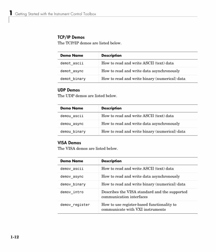
TCP/IP DemosThe TCP/IP demos are listed below.
UDP DemosThe UDP demos are listed below.
VISA DemosThe VISA demos are listed below.
Demo Name Description
demot_ascii How to read and write ASCII (text) data
demot_async How to read and write data asynchronously
demot_binary How to read and write binary (numerical) data
Demo Name Description
demou_ascii How to read and write ASCII (text) data
demou_async How to read and write data asynchronously
demou_binary How to read and write binary (numerical) data
Demo Name Description
demov_ascii How to read and write ASCII (text) data
demov_async How to read and write data asynchronously
demov_binary How to read and write binary (numerical) data
demov_intro Describes the VISA standard and the supported communication interfaces
demov_register How to use register-based functionality to communicate with VXI instruments

Examining Your Hardware Resources
1-13
Examining Your Hardware ResourcesYou can examine the hardware-related resources visible to the toolbox with the instrhwinfo function. The returned information includes the installed adaptors and the syntax for creating instrument objects. For instruments associated with the VISA standard, instrhwinfo also returns address information such as the GPIB board index, the VXI logical address, the VXI chassis, and so on.
The specific information returned by instrhwinfo depends on the supplied arguments, and is divided into these four categories:
• General toolbox information
• Interface information
• Adaptor information
• Instrument object information
General Toolbox InformationTo display general information about the Instrument Control Toolbox:
out = instrhwinfo
MATLABVersion: '6.5 (R13)' SupportedInterfaces: {'gpib' 'serial' 'visa' 'tcpip' 'udp'} ToolboxName: 'Instrument Control Toolbox' ToolboxVersion: '1.2 (R13)'
The SupportedInterfaces field lists the interfaces supported by the toolbox, but not necessarily the interfaces installed on your computer.
Interface InformationTo display information about a specific interface, you must supply the interface name as an argument to instrhwinfo. The interface name can be gpib, serial, tcpip, udp, or visa. For the serial port interface, the returned information includes the available serial ports. For the GPIB and VISA interfaces, the returned information includes the installed adaptors. For the TCP/IP and UDP interfaces, the information includes the local host address.
1 Getting Started with the Instrument Control Toolbox
1-14
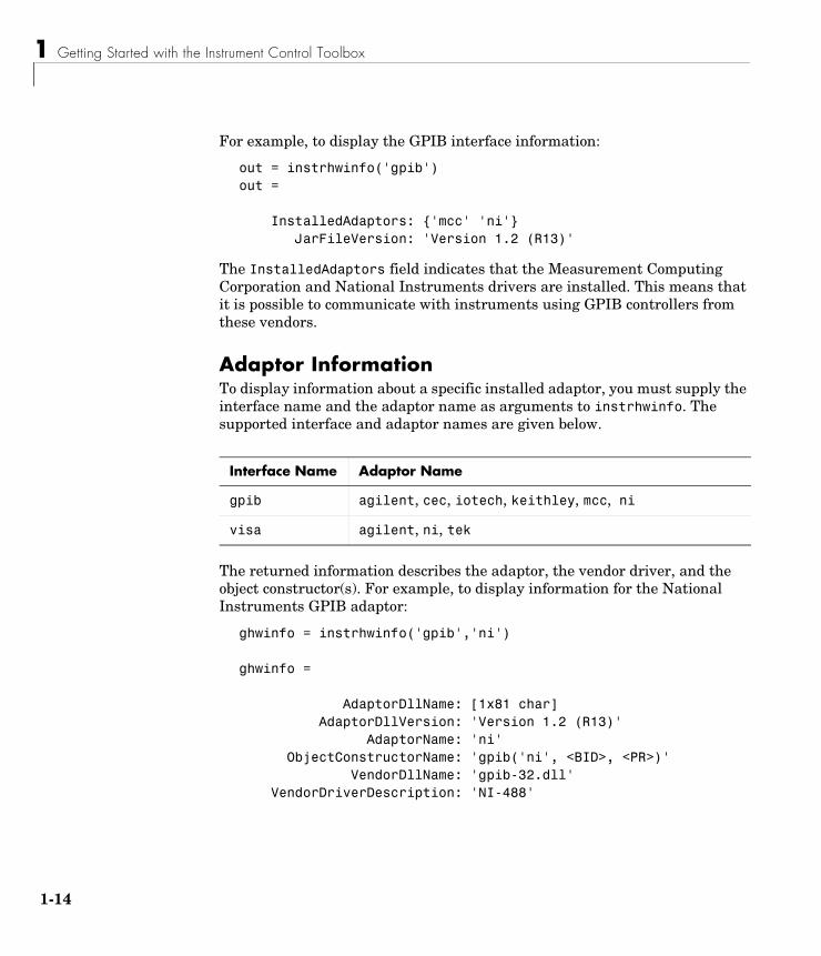
For example, to display the GPIB interface information:
out = instrhwinfo('gpib')out =
InstalledAdaptors: {'mcc' 'ni'} JarFileVersion: 'Version 1.2 (R13)'
The InstalledAdaptors field indicates that the Measurement Computing Corporation and National Instruments drivers are installed. This means that it is possible to communicate with instruments using GPIB controllers from these vendors.
Adaptor InformationTo display information about a specific installed adaptor, you must supply the interface name and the adaptor name as arguments to instrhwinfo. The supported interface and adaptor names are given below.
The returned information describes the adaptor, the vendor driver, and the object constructor(s). For example, to display information for the National Instruments GPIB adaptor:
ghwinfo = instrhwinfo('gpib','ni')
ghwinfo =
AdaptorDllName: [1x81 char] AdaptorDllVersion: 'Version 1.2 (R13)' AdaptorName: 'ni' ObjectConstructorName: 'gpib('ni', <BID>, <PR>)' VendorDllName: 'gpib-32.dll' VendorDriverDescription: 'NI-488'
Interface Name Adaptor Name
gpib agilent, cec, iotech, keithley, mcc, ni
visa agilent, ni, tek
Examining Your Hardware Resources
1-15
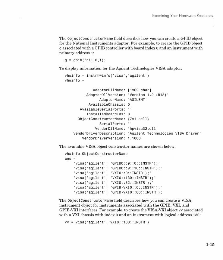
The ObjectConstructorName field describes how you can create a GPIB object for the National Instruments adaptor. For example, to create the GPIB object g associated with a GPIB controller with board index 0 and an instrument with primary address 1:
g = gpib('ni',0,1);
To display information for the Agilent Technologies VISA adaptor:
vhwinfo = instrhwinfo('visa','agilent')vhwinfo =
AdaptorDllName: [1x62 char] AdaptorDllVersion: 'Version 1.2 (R13)' AdaptorName: 'AGILENT' AvailableChassis: 0 AvailableSerialPorts: '' InstalledBoardIds: 0 ObjectConstructorName: {7x1 cell} SerialPorts: '' VendorDllName: 'hpvisa32.dll' VendorDriverDescription: 'Agilent Technologies VISA Driver' VendorDriverVersion: 1.1000
The available VISA object constructor names are shown below.
vhwinfo.ObjectConstructorNameans = 'visa('agilent', 'GPIB0::9::0::INSTR');' 'visa('agilent', 'GPIB0::9::10::INSTR');' 'visa('agilent', 'VXI0::0::INSTR');' 'visa('agilent', 'VXI0::130::INSTR');' 'visa('agilent', 'VXI0::32::INSTR');' 'visa('agilent', 'GPIB-VXI0::0::INSTR');' 'visa('agilent', 'GPIB-VXI0::80::INSTR');
The ObjectConstructorName field describes how you can create a VISA instrument object for instruments associated with the GPIB, VXI, and GPIB-VXI interfaces. For example, to create the VISA-VXI object vv associated with a VXI chassis with index 0 and an instrument with logical address 130:
vv = visa('agilent','VXI0::130::INSTR')
1 Getting Started with the Instrument Control Toolbox
1-16
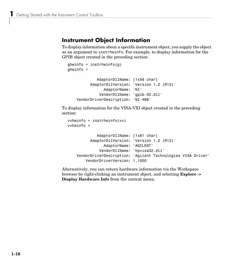
Instrument Object InformationTo display information about a specific instrument object, you supply the object as an argument to instrhwinfo. For example, to display information for the GPIB object created in the preceding section:
ghwinfo = instrhwinfo(g)ghwinfo =
AdaptorDllName: [1x56 char] AdaptorDllVersion: 'Version 1.2 (R13)' AdaptorName: 'NI' VendorDllName: 'gpib-32.dll' VendorDriverDescription: 'NI-488'
To display information for the VISA-VXI object created in the preceding section:
vvhwinfo = instrhwinfo(vv)vvhwinfo =
AdaptorDllName: [1x61 char] AdaptorDllVersion: 'Version 1.2 (R13)' AdaptorName: 'AGILENT' VendorDllName: 'hpvisa32.dll' VendorDriverDescription: 'Agilent Technologies VISA Driver' VendorDriverVersion: 1.1000
Alternatively, you can return hardware information via the Workspace browser by right-clicking an instrument object, and selecting Explore -> Display Hardware Info from the context menu.
Getting Help
1-17
Getting HelpThe Instrument Control Toolbox provides you with these help resources:
• The HTML and PDF versions of this guide, which are available through the Help browser
• M-file function help, which you can display with the help command (because many toolbox functions are overloaded, you might need to specify the appropriate pathname as well)
• The instrhelp function
• The propinfo function
The instrhelp FunctionYou can use the instrhelp function to
• Display command line help for functions and properties
• List all the functions and properties associated with a specific instrument object
An instrument object need not exist for you to obtain this information. For example, to display all the functions and properties associated with a GPIB object, as well as the constructor M-file help:
instrhelp gpib
To display help for the EOIMode property:
instrhelp EOIMode
You can also display help for an existing instrument object. For example, to display help for the MemorySpace property associated with a VISA-GPIB-VXI object:
v = visa('agilent','GPIB-VXI0::80::INSTR');out = instrhelp(v,'MemorySpace');
Alternatively, you can display help via the Workspace browser by right-clicking an instrument object, and selecting Explore -> Instrument Help from the context menu.
1 Getting Started with the Instrument Control Toolbox
1-18
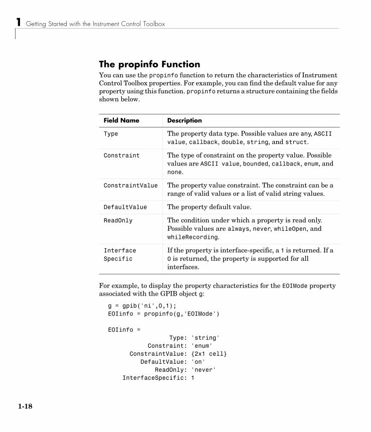
The propinfo FunctionYou can use the propinfo function to return the characteristics of Instrument Control Toolbox properties. For example, you can find the default value for any property using this function. propinfo returns a structure containing the fields shown below.
For example, to display the property characteristics for the EOIMode property associated with the GPIB object g:
g = gpib('ni',0,1);EOIinfo = propinfo(g,'EOIMode')
EOIinfo = Type: 'string' Constraint: 'enum' ConstraintValue: {2x1 cell} DefaultValue: 'on' ReadOnly: 'never' InterfaceSpecific: 1
Field Name Description
Type The property data type. Possible values are any, ASCII value, callback, double, string, and struct.
Constraint The type of constraint on the property value. Possible values are ASCII value, bounded, callback, enum, and none.
ConstraintValue The property value constraint. The constraint can be a range of valid values or a list of valid string values.
DefaultValue The property default value.
ReadOnly The condition under which a property is read only. Possible values are always, never, whileOpen, and whileRecording.
InterfaceSpecific
If the property is interface-specific, a 1 is returned. If a 0 is returned, the property is supported for all interfaces.
Getting Help
1-19
This information tells you that
• The property value data type is a string
• The property value is constrained as an enumerated list of values
• There are two possible property values
• The default value is on
• The property can be configured at any time (it is never read only)
• The property is not supported for all interfaces.
To display the property value constraints:
EOIinfo.ConstraintValueans = 'on' 'off'

1 Getting Started with the Instrument Control Toolbox
1-20

2The Instrument Control Session
The instrument control session consists of all the steps you are likely to take when communicating with your instrument. These steps are described in the following sections.
The instrument control session is used in many of the documentation examples included in this guide.
Creating an Instrument Object (p. 2-2)
Create a MATLAB object that represents the instrument.
Connecting to the Instrument (p. 2-5)
Establish a connection between the object and the instrument.
Configuring and Returning Properties (p. 2-6)
Define the instrument object behavior by assigning values to properties.
Writing and Reading Data (p. 2-12)
Write data to the instrument and read data from the instrument.
Disconnecting and Cleaning Up (p. 2-25)
Disconnect the object from the instrument, and remove the object from memory and from the workspace.
2 The Instrument Control Session
2-2
Creating an Instrument ObjectInstrument objects are the toolbox components you use to access your instrument. They provide a gateway to the functionality of your instrument, and allow you to control the behavior of your instrument control application. Each instrument object is associated with a specific interface standard, one instrument, and possibly additional hardware such as a GPIB or VXI controller.
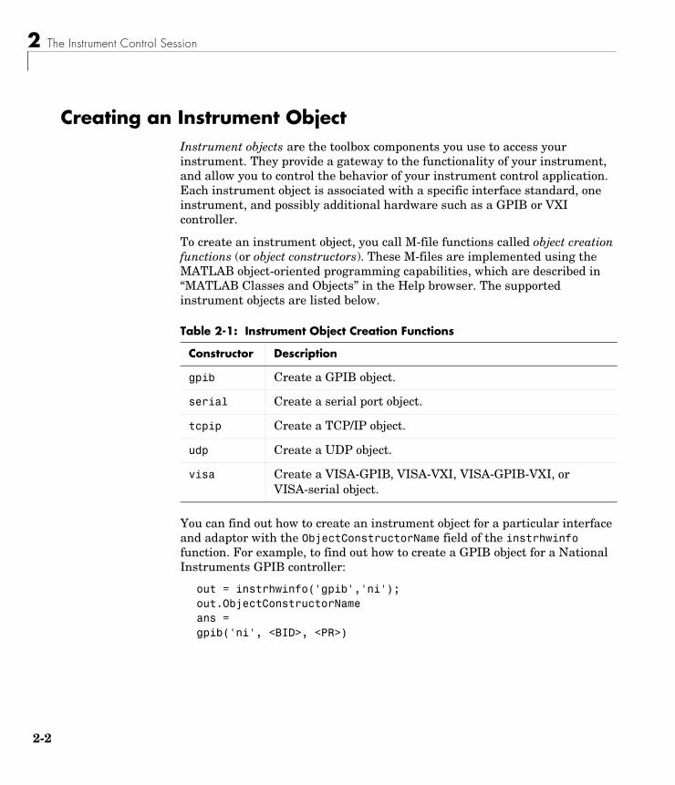
To create an instrument object, you call M-file functions called object creation functions (or object constructors). These M-files are implemented using the MATLAB object-oriented programming capabilities, which are described in “MATLAB Classes and Objects” in the Help browser. The supported instrument objects are listed below.
You can find out how to create an instrument object for a particular interface and adaptor with the ObjectConstructorName field of the instrhwinfo function. For example, to find out how to create a GPIB object for a National Instruments GPIB controller:
out = instrhwinfo('gpib','ni');out.ObjectConstructorNameans =gpib('ni', <BID>, <PR>)
Table 2-1: Instrument Object Creation Functions
Constructor Description
gpib Create a GPIB object.
serial Create a serial port object.
tcpip Create a TCP/IP object.
udp Create a UDP object.
visa Create a VISA-GPIB, VISA-VXI, VISA-GPIB-VXI, or VISA-serial object.

Creating an Instrument Object
2-3
The constructor syntax tells you that you must supply the GPIB controller’s board index and the instrument’s primary address to the gpib function. For example, to create a GPIB object with board index 0 and primary address 1:
g = gpib('ni',0,1);
Configuring Properties During Object CreationInstrument objects contain properties that reflect the functionality of your instrument. You control the behavior of your instrument control application by configuring values for these properties.
As described in “Configuring and Returning Properties” on page 2-6, you configure properties using the set function or the dot notation. You can also configure properties during object creation by specifying property name/property value pairs. For example, the following command configures the EOSMode and EOSCharCode properties for the GPIB object g.
g = gpib('ni',0,1,'EOSMode','read','EOSCharCode','CR');
If you specify an invalid property name or property value, the object is not created. However, if you specify a value that is not supported by your instrument, the object will be created but you will not be informed of the invalid value until you connect the object to the instrument with the fopen function. For example, suppose you configure the BaudRate property to 2. Although this is a valid value for the property, it is an invalid value for the instrument.
For more information about configuring properties, refer to “Configuring and Returning Properties” on page 2-6. For detailed property descriptions, refer to Chapter 9, “Property Reference.”
Creating an Array of Instrument ObjectsIn MATLAB, you can create an array from existing variables by concatenating those variables together. The same is true for instrument objects. For example, suppose you create the GPIB objects g1 and g2:
g1 = gpib('ni',0,1);g2 = gpib('ni',0,2);
2 The Instrument Control Session
2-4
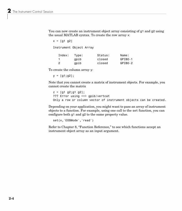
You can now create an instrument object array consisting of g1 and g2 using the usual MATLAB syntax. To create the row array x:
x = [g1 g2]
Instrument Object Array
Index: Type: Status: Name: 1 gpib closed GPIB0-1 2 gpib closed GPIB0-2
To create the column array y:
y = [g1;g2];
Note that you cannot create a matrix of instrument objects. For example, you cannot create the matrix
z = [g1 g2;g1 g2];??? Error using ==> gpib/vertcatOnly a row or column vector of instrument objects can be created.
Depending on your application, you might want to pass an array of instrument objects to a function. For example, using one call to the set function, you can configure both g1 and g2 to the same property value.
set(x,'EOSMode','read')
Refer to Chapter 8, “Function Reference,” to see which functions accept an instrument object array as an input argument.
Connecting to the Instrument
2-5
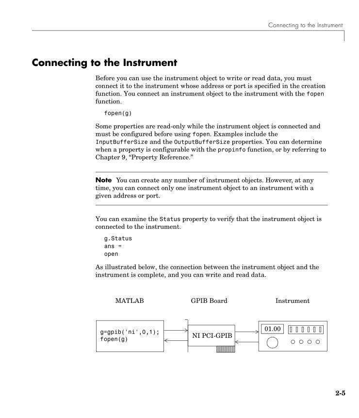
Connecting to the InstrumentBefore you can use the instrument object to write or read data, you must connect it to the instrument whose address or port is specified in the creation function. You connect an instrument object to the instrument with the fopen function.
fopen(g)
Some properties are read-only while the instrument object is connected and must be configured before using fopen. Examples include the InputBufferSize and the OutputBufferSize properties. You can determine when a property is configurable with the propinfo function, or by referring to Chapter 9, “Property Reference.”
Note You can create any number of instrument objects. However, at any time, you can connect only one instrument object to an instrument with a given address or port.
You can examine the Status property to verify that the instrument object is connected to the instrument.
g.Statusans =open
As illustrated below, the connection between the instrument object and the instrument is complete, and you can write and read data.
GPIB Board
g=gpib('ni',0,1);fopen(g)
01.00
InstrumentMATLAB
NI PCI-GPIB
2 The Instrument Control Session
2-6
Configuring and Returning PropertiesYou establish the desired instrument object behavior by configuring property values. You can configure property values using the set function or the dot notation, or by specifying property name/property value pairs during object creation. You can return property values using the get function or the dot notation.
Instrument objects possess two types of properties: base properties and object-specific properties. Base properties are supported for all instrument objects (serial port, GPIB, VISA-VXI, and so on). For example, the Timeout property is supported for all instrument objects. Object-specific properties are supported only for instrument objects of a given type. For example, the BaudRate property is supported only for serial port and VISA-serial objects.
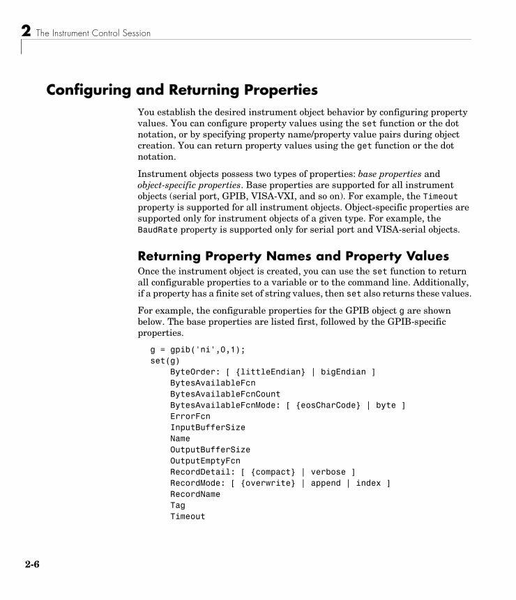
Returning Property Names and Property ValuesOnce the instrument object is created, you can use the set function to return all configurable properties to a variable or to the command line. Additionally, if a property has a finite set of string values, then set also returns these values.
For example, the configurable properties for the GPIB object g are shown below. The base properties are listed first, followed by the GPIB-specific properties.
g = gpib('ni',0,1);set(g) ByteOrder: [ {littleEndian} | bigEndian ] BytesAvailableFcn BytesAvailableFcnCount BytesAvailableFcnMode: [ {eosCharCode} | byte ] ErrorFcn InputBufferSize Name OutputBufferSize OutputEmptyFcn RecordDetail: [ {compact} | verbose ] RecordMode: [ {overwrite} | append | index ] RecordName Tag Timeout
Configuring and Returning Properties
2-7
TimerFcn TimerPeriod UserData GPIB specific properties: BoardIndex CompareBits EOIMode: [ {on} | off ] EOSCharCode EOSMode: [ {none} | read | write | read&write ] PrimaryAddress SecondaryAddress
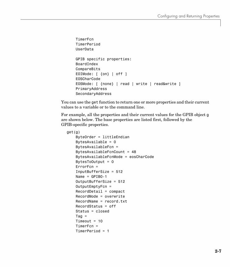
You can use the get function to return one or more properties and their current values to a variable or to the command line.
For example, all the properties and their current values for the GPIB object g are shown below. The base properties are listed first, followed by the GPIB-specific properties.
get(g) ByteOrder = littleEndian BytesAvailable = 0 BytesAvailableFcn = BytesAvailableFcnCount = 48 BytesAvailableFcnMode = eosCharCode BytesToOutput = 0 ErrorFcn = InputBufferSize = 512 Name = GPIB0-1 OutputBufferSize = 512 OutputEmptyFcn = RecordDetail = compact RecordMode = overwrite RecordName = record.txt RecordStatus = off Status = closed Tag = Timeout = 10 TimerFcn = TimerPeriod = 1

2 The Instrument Control Session
2-8
TransferStatus = idle Type = gpib UserData = [] ValuesReceived = 0 ValuesSent = 0
GPIB specific properties: BoardIndex = 0 BusManagementStatus = [1x1 struct] CompareBits = 8 EOIMode = on EOSCharCode = LF EOSMode = none HandshakeStatus = [1x1 struct] PrimaryAddress = 1 SecondaryAddress = 0
To display the current value for one property, you supply the property name to get.
get(g,'OutputBufferSize')ans = 512
To display the current values for multiple properties, you include the property names as elements of a cell array.
get(g,{'BoardIndex','TransferStatus'})ans = [0] 'idle'
You can also use the dot notation to display a single property value.
g.PrimaryAddressans = 1
Configuring and Returning Properties
2-9
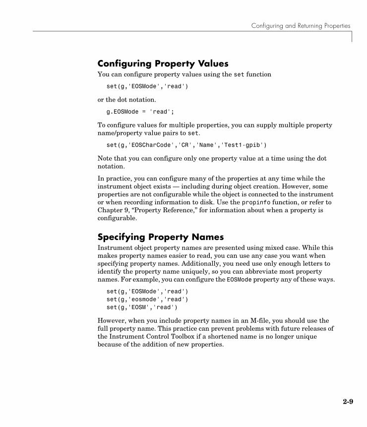
Configuring Property ValuesYou can configure property values using the set function
set(g,'EOSMode','read')
or the dot notation.
g.EOSMode = 'read';
To configure values for multiple properties, you can supply multiple property name/property value pairs to set.
set(g,'EOSCharCode','CR','Name','Test1-gpib')
Note that you can configure only one property value at a time using the dot notation.
In practice, you can configure many of the properties at any time while the instrument object exists — including during object creation. However, some properties are not configurable while the object is connected to the instrument or when recording information to disk. Use the propinfo function, or refer to Chapter 9, “Property Reference,” for information about when a property is configurable.
Specifying Property NamesInstrument object property names are presented using mixed case. While this makes property names easier to read, you can use any case you want when specifying property names. Additionally, you need use only enough letters to identify the property name uniquely, so you can abbreviate most property names. For example, you can configure the EOSMode property any of these ways.
set(g,'EOSMode','read')set(g,'eosmode','read')set(g,'EOSM','read')
However, when you include property names in an M-file, you should use the full property name. This practice can prevent problems with future releases of the Instrument Control Toolbox if a shortened name is no longer unique because of the addition of new properties.

2 The Instrument Control Session
2-10
Default Property ValuesIf you do not explicitly define a value for a property, then the default value is used. All configurable properties have default values.
Note Default values are provided for all instrument object properties. For serial port objects, the default values are provided by your operating system. For GPIB and VISA instrument objects, the default values are provided by vendor-supplied tools. However, these settings are overridden by your MATLAB code, and will have no effect on your instrument control application.
If a property has a finite set of string values, then the default value is enclosed by {} (curly braces). For example, the default value for the EOSMode property is none.
set(g,'EOSMode')[ {none} | read | write | read&write ]
You can also use the propinfo function, or refer to Chapter 9, “Property Reference” to find the default value for any property.
The Property InspectorThe Property Inspector enables you to inspect and set properties for one or more instrument objects. It provides a list of all properties and displays the current value.
Settable properties in the list are associated with an editing device that is appropriate for the values accepted by the particular property. For example, a callback configuration GUI to set ErrorFcn, a pop-up menu to set RecordMode, and a text field to specify the TimerPeriod. The values for read-only properties are grayed out.
You open the Property Inspector with the inspect function, or via the Workspace browser by right-clicking an instrument object and selecting Explore -> Call Property Inspector from the context menu.

Configuring and Returning Properties
2-11
The Property Inspector for the GPIB object g is shown below.
2 The Instrument Control Session
2-12
Writing and Reading DataCommunicating with your instrument involves writing and reading data. For example, you might write a text command to a function generator that queries its peak-to-peak voltage, and then read back the voltage value as a double-precision array.
Before performing a write or read operation, you should consider these three questions:
• What is the process by which data flows from MATLAB to the instrument, and from the instrument to MATLAB?
The Instrument Control Toolbox automatically manages the data transferred between MATLAB and the instrument. For many common applications, you can ignore the buffering and data flow process. However, if you are transferring a large number of values, executing an asynchronous read or write operation, or debugging your application, you might need to be aware of how this process works.
• Is the data to be transferred binary (numerical) or text (ASCII)?
For many instruments, writing text data means writing string commands that change instrument settings, prepare the instrument to return data or status information, and so on. Writing binary data means writing numerical values to the instrument such as calibration or waveform data.
• Will the write or read function block access to the MATLAB command line?
You control access to the MATLAB command line by specifying whether a read or write operation is synchronous or asynchronous. A synchronous operation blocks access to the command line until the read or write function completes execution. An asynchronous operation does not block access to the command, and you can issue additional commands while the read or write function executes in the background.
Note that there are other issues to consider when reading and writing data such as the conditions under which read or write operation completes. Because these issues vary among the supported interfaces, they are described in the respective interface-specific chapters.
Writing and Reading Data
2-13
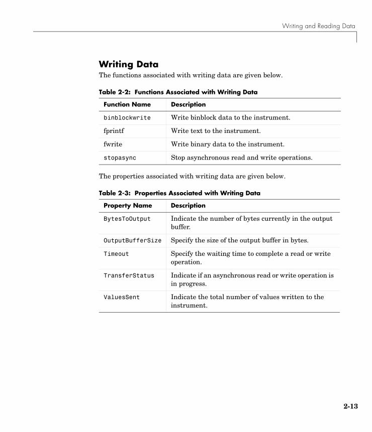
Writing DataThe functions associated with writing data are given below.
The properties associated with writing data are given below.
Table 2-2: Functions Associated with Writing Data
Function Name Description
binblockwrite Write binblock data to the instrument.
fprintf Write text to the instrument.
fwrite Write binary data to the instrument.
stopasync Stop asynchronous read and write operations.
Table 2-3: Properties Associated with Writing Data
Property Name Description
BytesToOutput Indicate the number of bytes currently in the output buffer.
OutputBufferSize Specify the size of the output buffer in bytes.
Timeout Specify the waiting time to complete a read or write operation.
TransferStatus Indicate if an asynchronous read or write operation is in progress.
ValuesSent Indicate the total number of values written to the instrument.
2 The Instrument Control Session
2-14
The Output Buffer and Data FlowThe output buffer is computer memory allocated by the instrument object to store data that is to be written to the instrument. The flow of data from MATLAB to your instrument follows these steps:
1 The data specified by the write function is sent to the output buffer.
2 The data in the output buffer is sent to the instrument.
The OutputBufferSize property specifies the maximum number of bytes that you can store in the output buffer. The BytesToOutput property indicates the number of bytes currently in the output buffer. The default values for these properties are given below.
g = gpib('ni',0,1);get(g,{'OutputBufferSize','BytesToOutput'})ans = [512] [0]
If you attempt to write more data than can fit in the output buffer, an error is returned and no data is written.
Note When writing data, you might need to specify a value, which can consist of one or more bytes. This is because some write functions allow you to control the number of bits written for each value and the interpretation of those bits as character, integer or floating point values. For example, if you write one value from an instrument using the int32 format, then that value consists of four bytes.
Writing and Reading Data
2-15
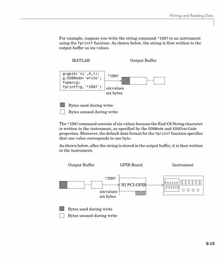
For example, suppose you write the string command *IDN? to an instrument using the fprintf function. As shown below, the string is first written to the output buffer as six values.
The *IDN? command consists of six values because the End-Of-String character is written to the instrument, as specified by the EOSMode and EOSCharCode properties. Moreover, the default data format for the fprintf function specifies that one value corresponds to one byte.
As shown below, after the string is stored in the output buffer, it is then written to the instrument.
g=gpib('ni',0,1);g.EOSMode='write';fopen(g)fprintf(g,'*IDN?')
...*IDN?
six values six bytes
MATLAB Output Buffer
Bytes used during write
Bytes unused during write
...
Output Buffer
Bytes used during write
Bytes unused during write
six values six bytes
Instrument
*IDN?
GPIB Board
NI PCI-GPIB
2 The Instrument Control Session
2-16
Writing Text Data Versus Writing Binary DataFor many instruments, writing text data means writing string commands that change instrument settings, prepare the instrument to return data or status information, and so on. Writing binary data means writing numerical values to the instrument such as calibration or waveform data.
You can write text data with the fprintf function. By default, fprintf uses the %s\n format, which formats the data as a string and includes the terminator. You can write binary data with the fwrite function. By default, fwrite writes data using the uchar precision, which translates the data as unsigned 8-bit characters. Both of these functions support many other formats and precisions, as described in their reference pages.
The following example illustrates writing text data and binary data to a Tektronix TDS 210 oscilloscope. The text data consists of string commands, while the binary data is a waveform that is to be downloaded to the scope and stored in its memory.
1 Create an instrument object — Create the GPIB object g associated with a National Instruments GPIB controller with board index 0, and an instrument with primary address 1. The size of the output buffer is increased to accommodate the waveform data. You must configure the OutputBufferSize property while the GPIB object is disconnected from the instrument.
g = gpib('ni',0,1);g.OutputBufferSize = 3000;
2 Connect to the instrument — Connect g to the instrument.
fopen(g)
3 Write and read data — Write string commands that configure the scope to store binary waveform data in memory location A.
fprintf(g,'DATA:DESTINATION REFA');fprintf(g,'DATA:ENCDG SRPbinary');fprintf(g,'DATA:WIDTH 1');fprintf(g,'DATA:START 1');
Writing and Reading Data
2-17
Create the waveform data.
t = linspace(0,25,2500);data = round(sin(t)*90 + 127);
Write the binary waveform data to the scope.
cmd = double('CURVE #42500');fwrite(g,[cmd data]);
The ValuesSent property indicates the total number of values that were written to the instrument.
g.ValuesSentans = 2577
4 Disconnect and clean up — When you no longer need g, you should disconnect it from the instrument, remove it from memory, and remove it from the MATLAB workspace.
fclose(g)delete(g)clear g
Synchronous Versus Asynchronous Write OperationsBy default, all write functions operate synchronously and block the MATLAB command line until the operation completes. To perform an asynchronous write operation, you must supply the async input argument to the fprintf or fwrite functions.
For example, you use the following syntax to modify the fprintf commands used in the preceding example to write text data asynchronously.
fprintf(g,'DATA:DESTINATION REFA','async');
Similarly, you use the following syntax to modify the fwrite command used in the preceding example to write binary data asynchronously.
fwrite(g,[cmd data],'async');
2 The Instrument Control Session
2-18
You can monitor the status of the asynchronous write operation with the TransferStatus property. A value of idle indicates that no asynchronous operations are in progress.
g.TransferStatusans =write
You can use the BytesToOutput property to indicate the numbers of bytes that exist in the output buffer waiting to be written to the instrument.
g.BytesToOutputans = 2512
Writing and Reading Data
2-19
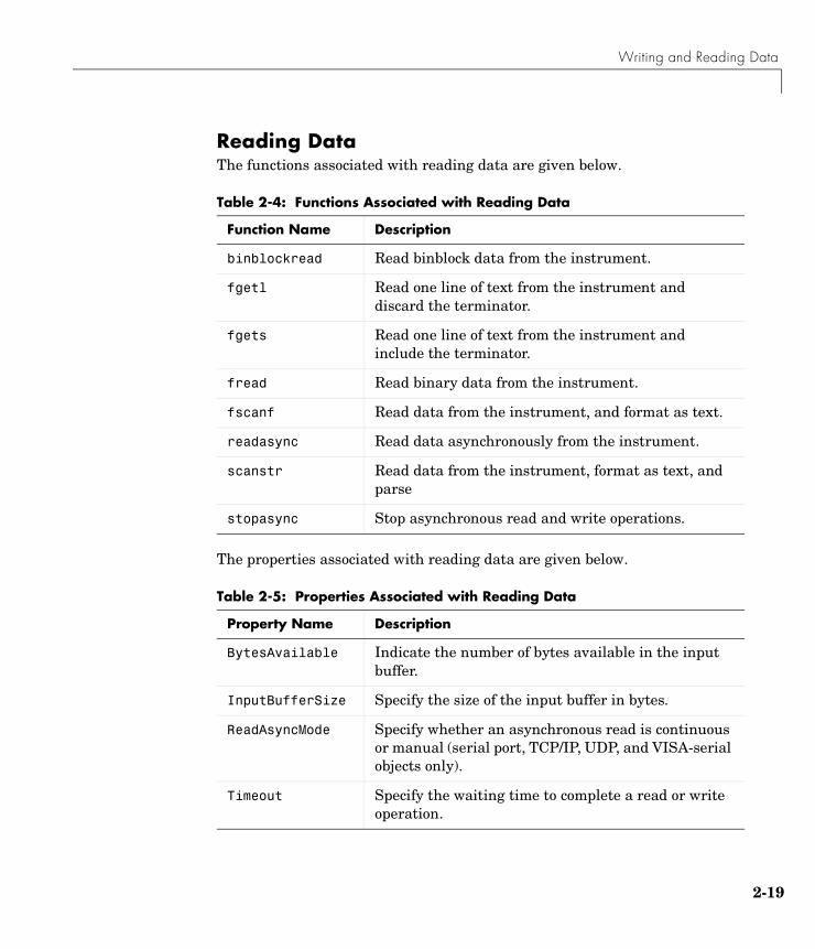
Reading DataThe functions associated with reading data are given below.
The properties associated with reading data are given below.
Table 2-4: Functions Associated with Reading Data
Function Name Description
binblockread Read binblock data from the instrument.
fgetl Read one line of text from the instrument and discard the terminator.
fgets Read one line of text from the instrument and include the terminator.
fread Read binary data from the instrument.
fscanf Read data from the instrument, and format as text.
readasync Read data asynchronously from the instrument.
scanstr Read data from the instrument, format as text, and parse
stopasync Stop asynchronous read and write operations.
Table 2-5: Properties Associated with Reading Data
Property Name Description
BytesAvailable Indicate the number of bytes available in the input buffer.
InputBufferSize Specify the size of the input buffer in bytes.
ReadAsyncMode Specify whether an asynchronous read is continuous or manual (serial port, TCP/IP, UDP, and VISA-serial objects only).
Timeout Specify the waiting time to complete a read or write operation.
2 The Instrument Control Session
2-20
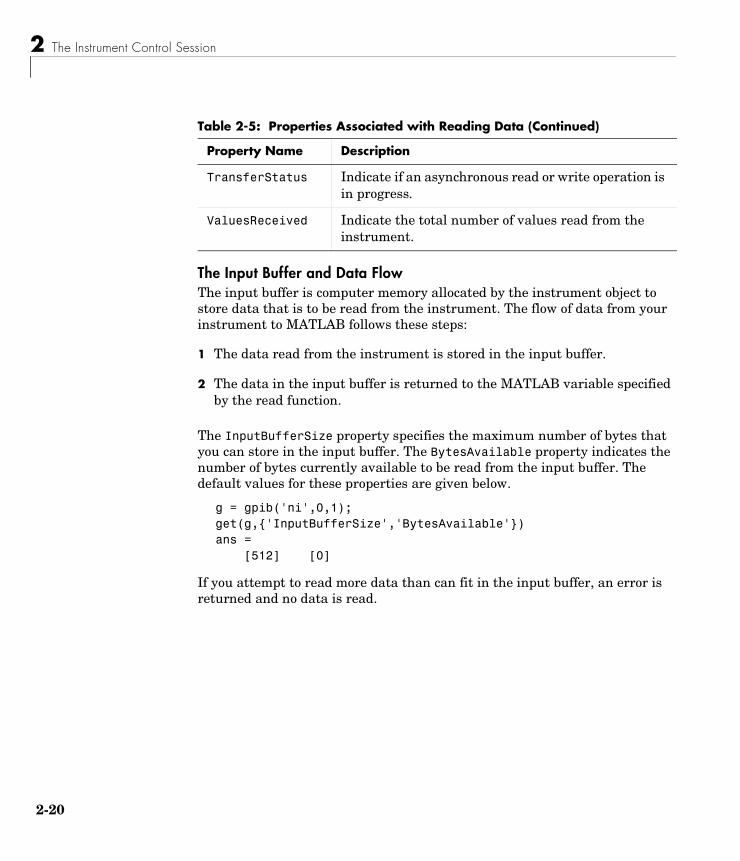
The Input Buffer and Data FlowThe input buffer is computer memory allocated by the instrument object to store data that is to be read from the instrument. The flow of data from your instrument to MATLAB follows these steps:
1 The data read from the instrument is stored in the input buffer.
2 The data in the input buffer is returned to the MATLAB variable specified by the read function.
The InputBufferSize property specifies the maximum number of bytes that you can store in the input buffer. The BytesAvailable property indicates the number of bytes currently available to be read from the input buffer. The default values for these properties are given below.
g = gpib('ni',0,1);get(g,{'InputBufferSize','BytesAvailable'})ans = [512] [0]
If you attempt to read more data than can fit in the input buffer, an error is returned and no data is read.
TransferStatus Indicate if an asynchronous read or write operation is in progress.
ValuesReceived Indicate the total number of values read from the instrument.
Table 2-5: Properties Associated with Reading Data (Continued)
Property Name Description
Writing and Reading Data
2-21
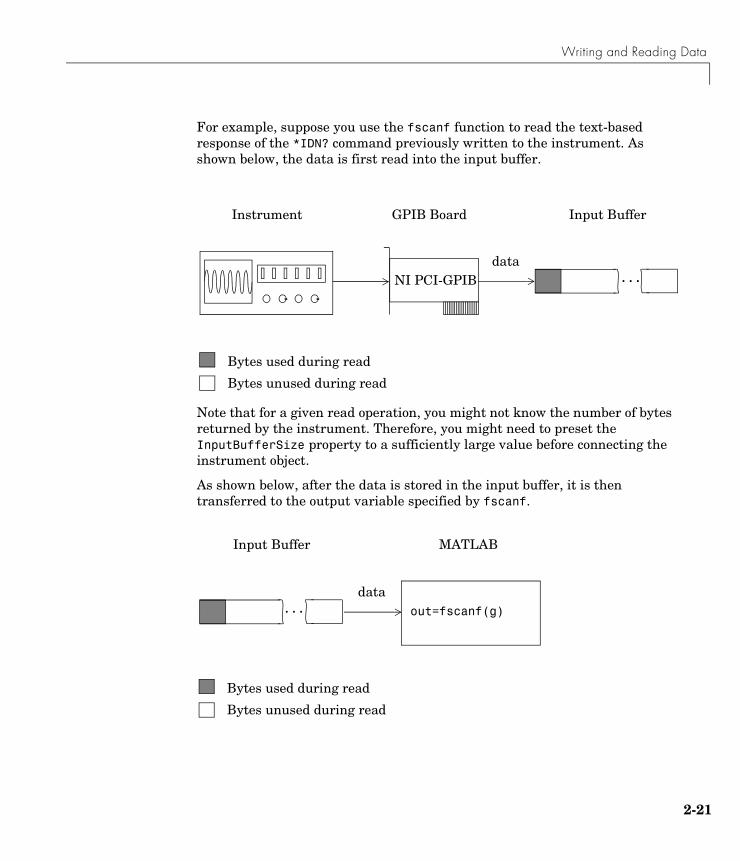
For example, suppose you use the fscanf function to read the text-based response of the *IDN? command previously written to the instrument. As shown below, the data is first read into the input buffer.
Note that for a given read operation, you might not know the number of bytes returned by the instrument. Therefore, you might need to preset the InputBufferSize property to a sufficiently large value before connecting the instrument object.
As shown below, after the data is stored in the input buffer, it is then transferred to the output variable specified by fscanf.
...
Input Buffer
Bytes used during read
Bytes unused during read
Instrument
data
GPIB Board
NI PCI-GPIB
out=fscanf(g)...
MATLABInput Buffer
Bytes used during read
Bytes unused during read
data
2 The Instrument Control Session
2-22
Reading Text Data Versus Reading Binary DataFor many instruments, reading text data means reading string data that reflect instrument settings, status information, and so on. Reading binary data means reading numerical values from the instrument.
You can read text data with the fgetl, fgets, and fscanf functions. By default, these functions return data using the %c format. You can read binary data with the fread function. By default, fread returns numerical values as double-precision arrays. Both the fscanf and fread functions support many other formats and precisions, as described in their reference pages.
The following example illustrates reading text data and binary data from a Tektronix TDS 210 oscilloscope, which is displaying a periodic input signal with a nominal frequency of 1.0 kHz.
1 Create an instrument object — Create the GPIB object g associated with a National Instruments GPIB controller with board index 0, and an instrument with primary address 1.
g = gpib('ni',0,1);
2 Connect to the instrument — Connect g to the instrument.
fopen(g)
3 Write and read data — Write the *IDN? command to the scope, and read back the identification information as text.
fprintf(g,'*IDN?')idn = fscanf(g)idn =TEKTRONIX,TDS 210,0,CF:91.1CT FV:v1.16 TDS2CM:CMV:v1.04
Configure the scope to return the period of the input signal, and then read the period as a binary value. The output display format is configured to use short exponential notation for doubles.
fprintf(g,'MEASUREMENT:MEAS1:TYPE PERIOD')fprintf(g,'MEASUREMENT:MEAS1:VALUE?')format short eperiod = fread(g,9)'period = 49 46 48 48 54 69 45 51 10

Writing and Reading Data
2-23
period consists of positive integers representing character codes, where 10 is a line feed. To convert the voltage value to a string, use the char function.
char(period)ans =1.006E-3
The ValuesReceived property indicates the total number of values that were read from the instrument.
g.ValuesReceivedans =
65
4 Disconnect and clean up — When you no longer need g, you should disconnect it from the instrument, remove it from memory, and remove it from the MATLAB workspace.
fclose(g)delete(g)clear g
Synchronous Versus Asynchronous Read OperationsThe fgetl, fgets, fscanf, and fread functions operate synchronously and block the MATLAB command line until the operation completes. To perform an asynchronous read operation, you must use the readasync function. readasync asynchronously reads data from the instrument and stores it in the input buffer. To transfer the data from the input buffer to a MATLAB variable, you must use one of the synchronous read functions.
Note For serial port, TCP/IP, UDP, and VISA-serial objects, you can also perform an asynchronous read operation by configuring the ReadAsyncMode property to continuous.
For example, to modify the preceding example to asynchronously read the scope’s identification information, you would issue the readasync function after the *IDN? command is written.
fprintf(g,'*IDN?')readasync(g)
2 The Instrument Control Session
2-24
You can monitor the status of the asynchronous read operation with the TransferStatus property. A value of idle indicates that no asynchronous operations are in progress.
g.TransferStatusans =read
You can use the BytesAvailable property to indicate the number of bytes that exist in the input buffer waiting to be transferred to MATLAB.
g.BytesAvailableans =
56
When the read completes, you can transfer the data as text to a MATLAB variable using the fscanf function.
idn = fscanf(g);

Disconnecting and Cleaning Up
2-25
Disconnecting and Cleaning UpWhen you no longer need an instrument object, you should disconnect it from the instrument, and clean up the MATLAB environment by removing the object from memory and from the workspace. These are the steps you take to end an instrument control session.
Disconnecting an Instrument ObjectWhen you no longer need to communicate with the instrument, you should disconnect it with the fclose function.
fclose(g)
You can examine the Status property to verify that the object and the instrument are disconnected.
g.Statusans =closed
After fclose is issued, the resources associated with g are made available, and you can once again connect an instrument object to the instrument with fopen.
Cleaning Up the MATLAB EnvironmentWhen you no longer need the instrument object, you should remove it from memory with the delete function.
delete(g)
Before using delete, you must disconnect the object from the instrument with the fclose function.
A deleted instrument object is invalid, which means that you cannot connect it to the instrument. In this case, you should remove the object from the MATLAB workspace. To remove instrument objects and other variables from the MATLAB workspace, use the clear command.
clear g
If you use clear on an object that is connected to an instrument, the object is removed from the workspace but remains connected to the instrument. You can restore cleared instrument objects to MATLAB with the instrfind function.

2 The Instrument Control Session
2-26
3Controlling GPIB Instruments
This chapter describes specific issues related to controlling instruments that use the GPIB interface. The sections are as follows.
GPIB Overview (p. 3-2) Basic features of the General Purpose Interface Bus (GPIB).
Creating a GPIB Object (p. 3-18)
The GPIB object establishes a connection between MATLAB and the instrument via its GPIB interface.
Configuring the GPIB Address (p. 3-20)
The GPIB address consists of the board index of the GPIB controller, and the primary address and (optionally) the secondary address of the instrument.
Writing and Reading Data (p. 3-21)
Interface-specific issues related to writing and reading data with a GPIB object.
Events and Callbacks (p. 3-30)
Enhance your instrument control application using events and callbacks.
Triggers (p. 3-37) Send the GET (Group Execute Trigger) GPIB command to the instrument. This command instructs all addressed Listeners to perform a specified action.
Serial Polls (p. 3-39) Execute a serial poll where the Controller asks (polls) all addressed Listeners to send back a status byte that indicates whether it has asserted the SRQ line and needs servicing.

3 Controlling GPIB Instruments
3-2
GPIB OverviewThis section provides an overview of the General Purpose Interface Bus (GPIB). Topics include
• What is GPIB?
• Important GPIB Features
• GPIB Lines
• Status and Event Reporting
• Using Vendor Tools to Identify and Test Your Resources
For many GPIB applications, you can communicate with your instrument without detailed knowledge of how GPIB works. Communication is established through a GPIB object, which you create in the MATLAB workspace.
If your application is straightforward, or if you are already familiar with the topics mentioned above, you might want to begin with “Creating a GPIB Object” on page 3-18. If you want a high-level description of all the steps you are likely to take when communicating with your instrument, refer to Chapter 2, “The Instrument Control Session.”
What Is GPIB?The GPIB is a standardized interface that allows you to connect and control multiple devices from various vendors. GPIB is also referred to by its original name HP-IB, or by its IEEE designation IEEE-488. The GPIB functionality has evolved over time, and is described in several specifications:
• The IEEE 488.1-1975 specification defines the electrical and mechanical characteristics of the interface and its basic functional characteristics.
• The IEEE-488.2-1987 specification builds on the IEEE 488.1 specification to define an acceptable minimum configuration and a basic set of instrument commands and common data formats.
• The Standard Commands for Programmable Instrumentation (SCPI) specification builds on the commands given by the IEEE 488.2 specification to define a standard instrument command set that can be used by GPIB or other interfaces.
Some of the GPIB functionality is required for all GPIB devices, while other GPIB functionality is optional. Additionally, many devices support only a
GPIB Overview
3-3
subset of the SCPI command set, or use a different vendor-specific command set. Refer to your device documentation for a complete list of its GPIB capabilities and its command set.
Important GPIB FeaturesThe important GPIB features are described below. For detailed information about GPIB functionality, refer to the appropriate references in Appendix A, “Selected Bibliography.”
The Bus and Connector The GPIB bus is a cable with two 24-pin connectors that allow you to connect multiple devices to each other. The bus and connector have these features and limitations:
• You can connect up to fifteen devices to a bus.
• You can connect devices in a star configuration, a linear configuration, or a combination of configurations.
• To achieve maximum data transfer rates, the cable length should not exceed 20 meters total or an average of 2 meters per device. You can eliminate these restrictions by using a bus extender.
GPIB Devices Each GPIB device must be some combination of a Talker, a Listener, or a Controller. A Controller is typically a board that you install in your computer. Talkers and Listeners are typically instruments such as oscilloscopes, function generators, multimeters, and so on. Most modern instruments are both Talkers and Listeners.
• Talkers — A Talker transmits data over the interface when addressed to talk by the Controller. There can be only one Talker at a given time.
• Listeners — A Listener receives data over the interface when addressed to listen by the Controller. There can be up to 14 Listeners at a given time. Typically, the Controller is a Talker while one or more instruments on the GPIB are Listeners.
• Controllers — The Controller specifies which devices are Talkers or Listeners. A GPIB system can contain multiple Controllers — one of which is designated the System Controller. However, only one Controller can be
3 Controlling GPIB Instruments
3-4
active at a given time. The current active controller is the Controller-In-Charge (CIC). The CIC can pass control to an idle Controller, but only the System Controller can make itself the CIC.
When the Controller is not sending messages, then a Talker can send messages. Typically, the CIC is a Listener while another device is enabled as a Talker.
Each Controller is identified by a unique board index number. Each Talker/Listener is identified by a unique primary address ranging from 0 to 30, and by an optional secondary address, which can be 0 or can range from 96 to 126.
GPIB DataThere are two types of data that can be transferred over the GPIB: instrument data and interface messages.
• Instrument data — Instrument data consists of vendor-specific commands that configure your instrument, return measurement results, and so on. For a complete list of commands supported by your instrument, refer to its documentation.
• Interface messages — Interface messages are defined by the GPIB standard and consist of commands that clear the GPIB bus, address devices, return self-test results, and so on.
Data transfer consists of one byte (8 bits) sent in parallel.The data transfer rate across the interface is limited to 1 megabyte per second. However, this data rate is usually not achieved in practice, and is limited by the slowest device on the bus.
GPIB LinesThe GPIB consists of 24 lines, which are shared by all instruments connected to the bus. 16 lines are used for signals, while 8 lines are for ground. The signal lines are divided into these groups:
• Eight data lines
• Five interface management lines
• Three handshake lines
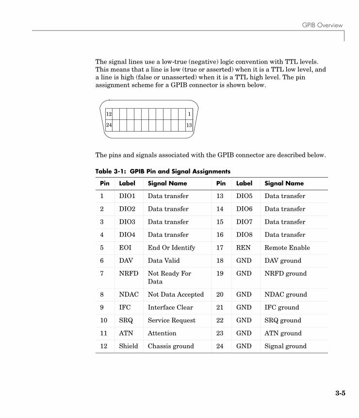
GPIB Overview
3-5
The signal lines use a low-true (negative) logic convention with TTL levels. This means that a line is low (true or asserted) when it is a TTL low level, and a line is high (false or unasserted) when it is a TTL high level. The pin assignment scheme for a GPIB connector is shown below.
The pins and signals associated with the GPIB connector are described below.
Table 3-1: GPIB Pin and Signal Assignments
Pin Label Signal Name Pin Label Signal Name
1 DIO1 Data transfer 13 DIO5 Data transfer
2 DIO2 Data transfer 14 DIO6 Data transfer
3 DIO3 Data transfer 15 DIO7 Data transfer
4 DIO4 Data transfer 16 DIO8 Data transfer
5 EOI End Or Identify 17 REN Remote Enable
6 DAV Data Valid 18 GND DAV ground
7 NRFD Not Ready For Data
19 GND NRFD ground
8 NDAC Not Data Accepted 20 GND NDAC ground
9 IFC Interface Clear 21 GND IFC ground
10 SRQ Service Request 22 GND SRQ ground
11 ATN Attention 23 GND ATN ground
12 Shield Chassis ground 24 GND Signal ground
112
1324
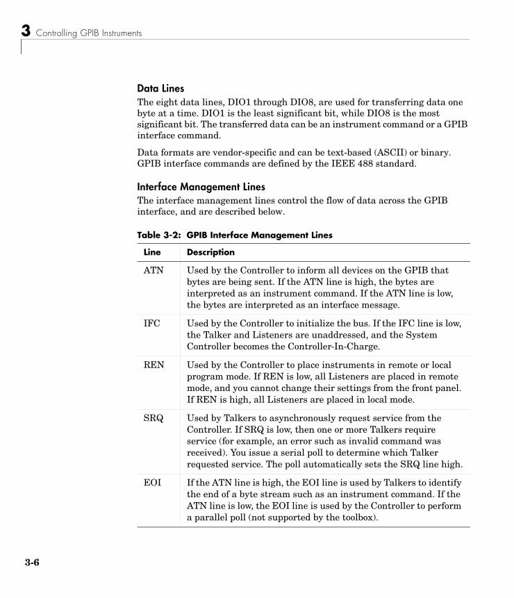
3 Controlling GPIB Instruments
3-6
Data LinesThe eight data lines, DIO1 through DIO8, are used for transferring data one byte at a time. DIO1 is the least significant bit, while DIO8 is the most significant bit. The transferred data can be an instrument command or a GPIB interface command.
Data formats are vendor-specific and can be text-based (ASCII) or binary. GPIB interface commands are defined by the IEEE 488 standard.
Interface Management LinesThe interface management lines control the flow of data across the GPIB interface, and are described below.
Table 3-2: GPIB Interface Management Lines
Line Description
ATN Used by the Controller to inform all devices on the GPIB that bytes are being sent. If the ATN line is high, the bytes are interpreted as an instrument command. If the ATN line is low, the bytes are interpreted as an interface message.
IFC Used by the Controller to initialize the bus. If the IFC line is low, the Talker and Listeners are unaddressed, and the System Controller becomes the Controller-In-Charge.
REN Used by the Controller to place instruments in remote or local program mode. If REN is low, all Listeners are placed in remote mode, and you cannot change their settings from the front panel. If REN is high, all Listeners are placed in local mode.
SRQ Used by Talkers to asynchronously request service from the Controller. If SRQ is low, then one or more Talkers require service (for example, an error such as invalid command was received). You issue a serial poll to determine which Talker requested service. The poll automatically sets the SRQ line high.
EOI If the ATN line is high, the EOI line is used by Talkers to identify the end of a byte stream such as an instrument command. If the ATN line is low, the EOI line is used by the Controller to perform a parallel poll (not supported by the toolbox).
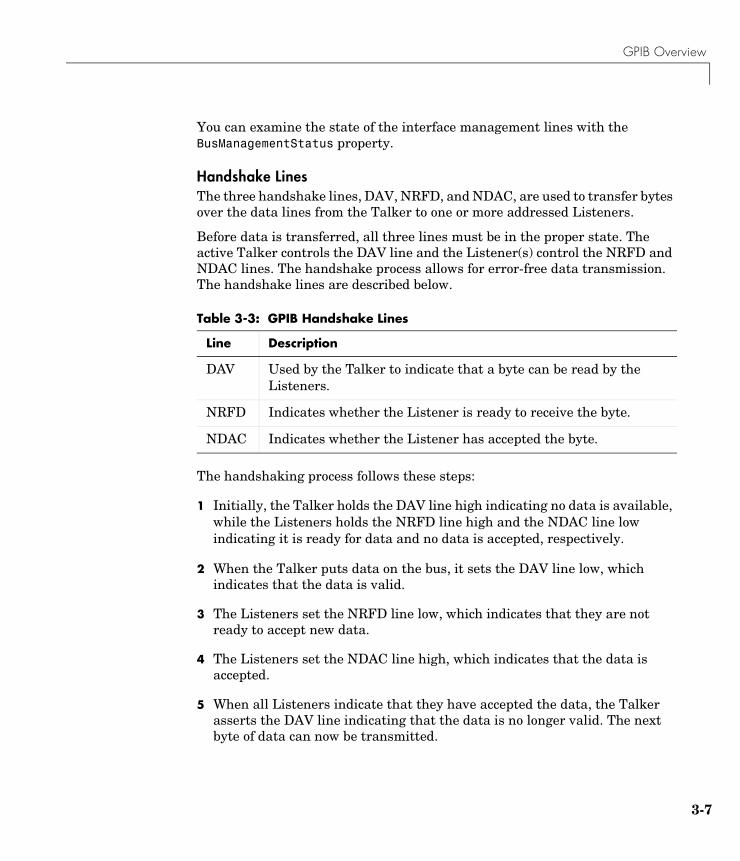
GPIB Overview
3-7
You can examine the state of the interface management lines with the BusManagementStatus property.
Handshake LinesThe three handshake lines, DAV, NRFD, and NDAC, are used to transfer bytes over the data lines from the Talker to one or more addressed Listeners.
Before data is transferred, all three lines must be in the proper state. The active Talker controls the DAV line and the Listener(s) control the NRFD and NDAC lines. The handshake process allows for error-free data transmission. The handshake lines are described below.
The handshaking process follows these steps:
1 Initially, the Talker holds the DAV line high indicating no data is available, while the Listeners holds the NRFD line high and the NDAC line low indicating it is ready for data and no data is accepted, respectively.
2 When the Talker puts data on the bus, it sets the DAV line low, which indicates that the data is valid.
3 The Listeners set the NRFD line low, which indicates that they are not ready to accept new data.
4 The Listeners set the NDAC line high, which indicates that the data is accepted.
5 When all Listeners indicate that they have accepted the data, the Talker asserts the DAV line indicating that the data is no longer valid. The next byte of data can now be transmitted.
Table 3-3: GPIB Handshake Lines
Line Description
DAV Used by the Talker to indicate that a byte can be read by the Listeners.
NRFD Indicates whether the Listener is ready to receive the byte.
NDAC Indicates whether the Listener has accepted the byte.
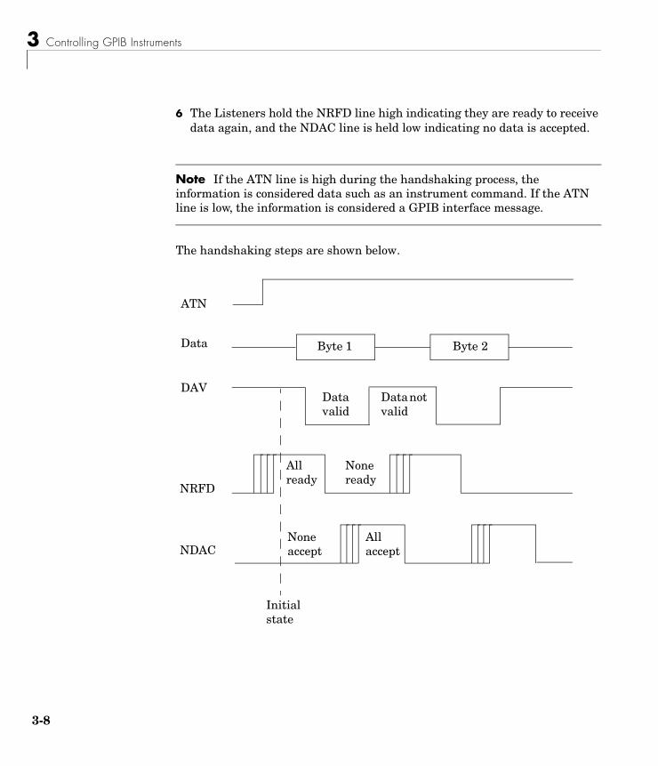
3 Controlling GPIB Instruments
3-8
6 The Listeners hold the NRFD line high indicating they are ready to receive data again, and the NDAC line is held low indicating no data is accepted.
Note If the ATN line is high during the handshaking process, the information is considered data such as an instrument command. If the ATN line is low, the information is considered a GPIB interface message.
The handshaking steps are shown below.
Data
NRFD
NDAC
ATN
DAV
Initial state
Byte 1 Byte 2
Data valid
Data not valid
None ready
None accept
All accept
All ready
GPIB Overview
3-9
You can examine the state of the handshake lines with the HandshakeStatus property.
Status and Event ReportingGPIB provides a system for reporting status and event information. With this system, you can find out if your instrument has data to return, whether a command error occurred, and so on. For many instruments, the reporting system consists of four 8-bit registers and two queues (output and event). The four registers are grouped into these two functional categories:
• Status Registers — The Status Byte Register (SBR) and Standard Event Status Register (SESR) contain information about the state of the instrument.
• Enable Registers — The Event Status Enable Register (ESER) and the Service Request Enable Register (SRER) determine which types of events are reported to the status registers and the event queue. ESER enables SESR, while SRER enables SBR.

3 Controlling GPIB Instruments
3-10
The status registers, enable registers, and output queue are shown below.
Standard Event
Output Queue
PON URQ CME EXE DDE QYE RQC OPC
bit 7 bit 0
PON URQ CME EXE DDE QYE RQC OPC
Logical OR
– ESB MAV – – – –
– ESB MAV – – – –
Standard Event Status Register
Standard Event Status Enable Register
Service Request Enable Register
bit 0bit 7
Status Byte RegisterRQS
MSS
Logical OR
Data available on instrument ready to be sent across the bus
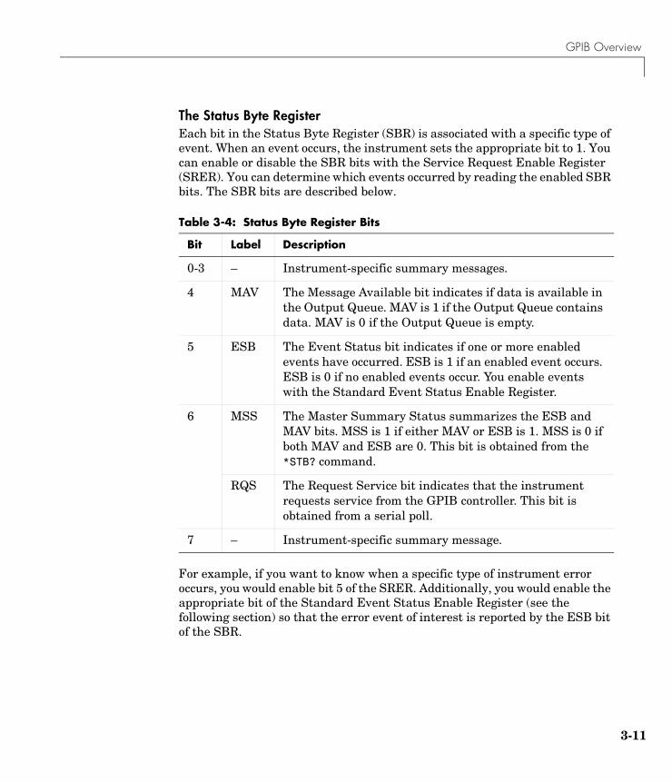
GPIB Overview
3-11
The Status Byte RegisterEach bit in the Status Byte Register (SBR) is associated with a specific type of event. When an event occurs, the instrument sets the appropriate bit to 1. You can enable or disable the SBR bits with the Service Request Enable Register (SRER). You can determine which events occurred by reading the enabled SBR bits. The SBR bits are described below.
For example, if you want to know when a specific type of instrument error occurs, you would enable bit 5 of the SRER. Additionally, you would enable the appropriate bit of the Standard Event Status Enable Register (see the following section) so that the error event of interest is reported by the ESB bit of the SBR.
Table 3-4: Status Byte Register Bits
Bit Label Description
0-3 – Instrument-specific summary messages.
4 MAV The Message Available bit indicates if data is available in the Output Queue. MAV is 1 if the Output Queue contains data. MAV is 0 if the Output Queue is empty.
5 ESB The Event Status bit indicates if one or more enabled events have occurred. ESB is 1 if an enabled event occurs. ESB is 0 if no enabled events occur. You enable events with the Standard Event Status Enable Register.
6 MSS The Master Summary Status summarizes the ESB and MAV bits. MSS is 1 if either MAV or ESB is 1. MSS is 0 if both MAV and ESB are 0. This bit is obtained from the *STB? command.
RQS The Request Service bit indicates that the instrument requests service from the GPIB controller. This bit is obtained from a serial poll.
7 – Instrument-specific summary message.
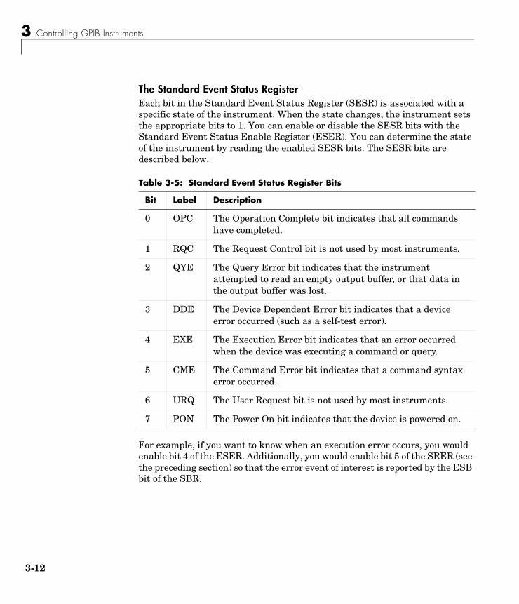
3 Controlling GPIB Instruments
3-12
The Standard Event Status RegisterEach bit in the Standard Event Status Register (SESR) is associated with a specific state of the instrument. When the state changes, the instrument sets the appropriate bits to 1. You can enable or disable the SESR bits with the Standard Event Status Enable Register (ESER). You can determine the state of the instrument by reading the enabled SESR bits. The SESR bits are described below.
For example, if you want to know when an execution error occurs, you would enable bit 4 of the ESER. Additionally, you would enable bit 5 of the SRER (see the preceding section) so that the error event of interest is reported by the ESB bit of the SBR.
Table 3-5: Standard Event Status Register Bits
Bit Label Description
0 OPC The Operation Complete bit indicates that all commands have completed.
1 RQC The Request Control bit is not used by most instruments.
2 QYE The Query Error bit indicates that the instrument attempted to read an empty output buffer, or that data in the output buffer was lost.
3 DDE The Device Dependent Error bit indicates that a device error occurred (such as a self-test error).
4 EXE The Execution Error bit indicates that an error occurred when the device was executing a command or query.
5 CME The Command Error bit indicates that a command syntax error occurred.
6 URQ The User Request bit is not used by most instruments.
7 PON The Power On bit indicates that the device is powered on.

GPIB Overview
3-13
Reading and Writing Register InformationThis section describes the common GPIB commands used to read and write status and event register information.
For example, to enable bit 4 of the SESR, you write the command *ESE 16. To enable bit 4 and bit 5 of the SESR, you write the command *ESE 48. To enable bit 5 of the SBR, you write the command *SRE 32.
To see how to use many of these commands in the context of an instrument control session, refer to “Example: Executing a Serial Poll” on page 3-39.
Table 3-6: GPIB Commands for Reading and Writing Register Information
Register Operation Command Description
SESR Read *ESR? Return a decimal value that corresponds to the weighted sum of all the bits set in the SESR register.
Write N/A You cannot write to the SESR register.
ESER Read *ESE? Return a decimal value that corresponds to the weighted sum of all the bits enabled by the *ESE command.
Write *ESE Write a decimal value that corresponds to the weighted sum of all the bits you want to enable in the SESR register.
SBR Read *STB? Return a decimal value that corresponds to the weighted sum of all the bits set in the SBR register. This command returns the same result as a serial poll except that the MSS bit is not cleared.
Write N/A You cannot write to the SBR register.
SRER Read *SRE? Return a decimal value that corresponds to the weighted sum of all the bits enabled by the *SRE command.
Write *SRE Write a decimal value that corresponds to the weighted sum of all the bits you want to enable in the SBR register.

3 Controlling GPIB Instruments
3-14
Using Vendor Tools to Identify and Test Your ResourcesThe supported GPIB vendors provide tools that allow you to identify, configure, and test the GPIB resources in your system. These tools are usually installed in conjunction with the GPIB drivers. You should use these tools to
• Determine the GPIB board index, which is used to create a GPIB object. Some tools also determine address information for connected and powered instruments (see below).
• Test the GPIB interface.
For example, National Instruments’ Measurement & Automation tool is shown below. The display indicates that a GPIB controller with board index 0 is available on the system. By selecting the name of the controller and right-clicking, you can perform several helpful tasks via the drop-down menu. For example, you can scan for instruments, use the NI-488.2 Getting Started Wizard to verify the GPIB driver and controller installation, or use the NI-488.2 Troubleshooting Wizard to test the GPIB interface.
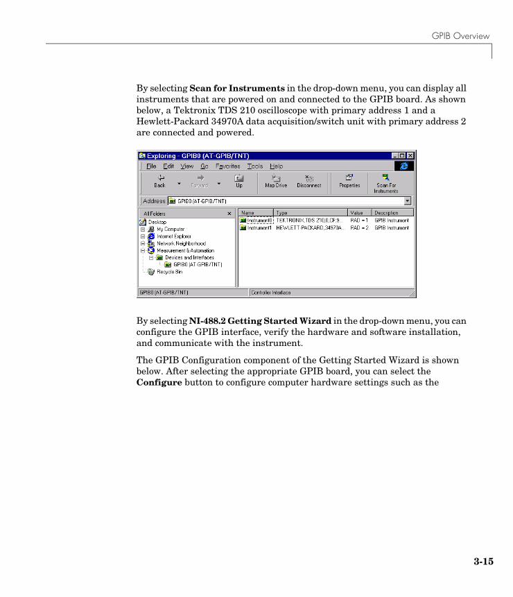
GPIB Overview
3-15
By selecting Scan for Instruments in the drop-down menu, you can display all instruments that are powered on and connected to the GPIB board. As shown below, a Tektronix TDS 210 oscilloscope with primary address 1 and a Hewlett-Packard 34970A data acquisition/switch unit with primary address 2 are connected and powered.
By selecting NI-488.2 Getting Started Wizard in the drop-down menu, you can configure the GPIB interface, verify the hardware and software installation, and communicate with the instrument.
The GPIB Configuration component of the Getting Started Wizard is shown below. After selecting the appropriate GPIB board, you can select the Configure button to configure computer hardware settings such as the
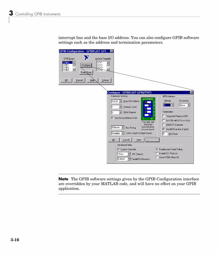
3 Controlling GPIB Instruments
3-16
interrupt line and the base I/O address. You can also configure GPIB software settings such as the address and termination parameters.
Note The GPIB software settings given by the GPIB Configuration interface are overridden by your MATLAB code, and will have no effect on your GPIB application.
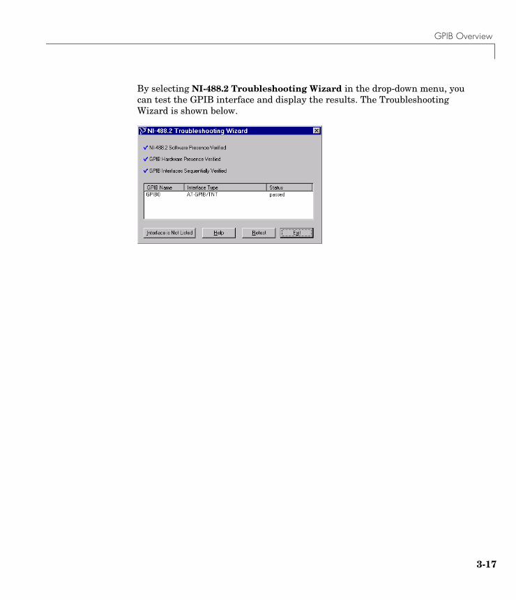
GPIB Overview
3-17
By selecting NI-488.2 Troubleshooting Wizard in the drop-down menu, you can test the GPIB interface and display the results. The Troubleshooting Wizard is shown below.
3 Controlling GPIB Instruments
3-18
Creating a GPIB ObjectYou create a GPIB object with the gpib function. gpib requires the adaptor name, the GPIB board index, and the primary address of the instrument. As described in “Configuring Properties During Object Creation” on page 2-3, you can also configure property values during object creation. For a list of supported adaptors, refer to “The Interface Driver Adaptor” on page 1-4.
Each GPIB object is associated with one controller and one instrument. For example, to create a GPIB object associated with a National Instruments controller with board index 0, and an instrument with primary address 1:
g = gpib('ni',0,1);
The GPIB object g now exists in the MATLAB workspace. You can display the class of g with the whos command.
whos g Name Size Bytes Class
g 1x1 636 gpib object
Grand total is 14 elements using 636 bytes
Once the GPIB object is created, the properties listed below are automatically assigned values. These general purpose properties provide descriptive information about the object based on its class type and address information.
You can display the values of these properties for g with the get function.
get(g,{'Name','Type'})ans = 'GPIB0-1' 'gpib'
Table 3-7: GPIB Descriptive Properties
Property Name Description
Name Specify a descriptive name for the GPIB object.
Type Indicate the object type.
Creating a GPIB Object
3-19
The GPIB Object DisplayThe GPIB object provides you with a convenient display that summarizes important address and state information. You can invoke the display summary these ways:
• Type the GPIB object at the command line.
• Exclude the semicolon when creating a GPIB object.
• Exclude the semicolon when configuring properties using the dot notation.
You can also display summary information via the Workspace browser by right-clicking an instrument object and selecting Explore -> Display Summary from the context menu.
The display summary for the GPIB object g is given below.
GPIB Object Using NI Adaptor : GPIB0-1
Communication Address BoardIndex: 0PrimaryAddress: 1SecondaryAddress: 0
Communication State Status: closedRecordStatus: off
Read/Write State TransferStatus: idleBytesAvailable: 0ValuesReceived: 0ValuesSent: 0
3 Controlling GPIB Instruments
3-20
Configuring the GPIB AddressEach GPIB object is associated with one controller and one instrument. The GPIB address consists of the board index of the GPIB controller, and the primary address and (optionally) the secondary address of the instrument. The term “board index” is equivalent to the term “logical unit” as used by Agilent Technologies.
As described in “Using Vendor Tools to Identify and Test Your Resources” on page 3-14, you can find the GPIB board index number by invoking the appropriate vendor tool. Note that some vendors place limits on the allowed board index values. Refer to the Instrument Control Toolbox Release Notes for a list of these limitations. You can usually find the instrument addresses through a front panel display or by examining dip switch settings. Valid primary addresses range from 0 to 30. Valid secondary addresses range from 96 to 126, or it can be 0 indicating that no secondary address is used.
The properties associated with the GPIB address are given below.
You must specify the board index and instrument primary address values during GPIB object creation. The BoardIndex and PrimaryAddress properties are automatically updated with these values. If the instrument has a secondary address, you can specify its value during or after object creation by configuring the SecondaryAddress property.
You can display the address property values for the GPIB object g created in “Creating a GPIB Object” on page 3-18 with the get function.
get(g,{'BoardIndex','PrimaryAddress','SecondaryAddress'})ans = [0] [1] [0]
Table 3-8: GPIB Address Properties
Property Name Description
BoardIndex Specify the index number of the GPIB board.
PrimaryAddress Specify the primary address of the GPIB instrument.
SecondaryAddress Specify the secondary address of the GPIB instrument.

Writing and Reading Data
3-21
Writing and Reading DataThis section describes interface-specific issues related to writing and reading data with a GPIB object. Topics include
• The rules for completing write and read operations
• Examples that illustrate writing and reading text data and binary data
For a general overview about writing and reading data, as well as a list of all associated functions and properties, refer to “Writing and Reading Data” on page 2-12.
Rules for Completing Write and Read OperationsThe rules for completing synchronous and asynchronous read and write operations are described below.
Completing Write OperationsA write operation using fprintf or fwrite completes when one of these conditions is satisfied:
• The specified data is written.
• The time specified by the Timeout property passes.
Additionally, you can stop an asynchronous write operation at any time with the stopasync function.
An instrument determines if a write operation is complete based on the EOSMode, EOIMode, and EOSCharCode property values. If EOSMode is configured to either write or read&write, each occurrence of \n in a text command is replaced with the End-Of-String (EOS) character specified by the EOSCharCode value. Therefore, when you use the default fprintf format of %s\n, all text commands written to the instrument will end with that value. The default EOSCharCode value is LF, which corresponds to the line feed character. The EOS character required by your instrument will be described in its documentation.
If EOIMode is on, then the End Or Identify (EOI) line is asserted when the last byte is written to the instrument. The last byte can be part of a binary data stream or a text data stream. If EOSMode is configured to either write or read&write, then the last byte written is the EOSCharCode value and the EOI line is asserted when the instrument receives this byte.

3 Controlling GPIB Instruments
3-22
Completing Read OperationsA read operation with fgetl, fgets, fread, fscanf, or readasync completes when one of these conditions is satisfied:
• The EOI line is asserted.
• The terminator specified by the EOSCharCode property is read. This can occur only when the EOSMode property is configured to either read or read&write.
• The time specified by the Timeout property passes.
• The specified number of values is read (fread, fscanf, and readasync only).
• The input buffer is filled (if the number of values is not specified).
In addition to these rules, you can stop an asynchronous read operation at any time with the stopasync function.
Example: Writing and Reading Text DataThis example illustrates how to communicate with a GPIB instrument by writing and reading text data.
The instrument is a Tektronix TDS 210 two-channel oscilloscope. Therefore, many of the commands used are specific to this instrument. A sine wave is input into channel 2 of the oscilloscope, and your job is to measure the peak-to-peak voltage of the input signal.
1 Create an instrument object — Create the GPIB object g associated with a National Instruments GPIB controller with board index 0, and an instrument with primary address 1.
g = gpib('ni',0,1);
2 Connect to the instrument — Connect g to the oscilloscope, and return the default values for the EOSMode and EOIMode properties.
fopen(g)get(g,{'EOSMode','EOIMode'})ans = 'none' 'on'
Using these property values, write operations complete when the last byte is written to the instrument, and read operations complete when the EOI line is asserted by the instrument.
Writing and Reading Data
3-23
3 Write and read data — Write the *IDN? command to the instrument using fprintf, and then read back the result of the command using fscanf.
fprintf(g,'*IDN?')idn = fscanf(g)idn =TEKTRONIX,TDS 210,0,CF:91.1CT FV:v1.16 TDS2CM:CMV:v1.04
Determine the measurement source. Possible measurement sources include channel 1 and channel 2 of the oscilloscope.
fprintf(g,'MEASUREMENT:IMMED:SOURCE?')source = fscanf(g)source =CH1
The scope is configured to return a measurement from channel 1. Because the input signal is connected to channel 2, you must configure the instrument to return a measurement from this channel.
fprintf(g,'MEASUREMENT:IMMED:SOURCE CH2')fprintf(g,'MEASUREMENT:IMMED:SOURCE?')source = fscanf(g)source =CH2
You can now configure the scope to return the peak-to-peak voltage, request the value of this measurement, and then return the voltage value to MATLAB using fscanf.
fprintf(g,'MEASUREMENT:MEAS1:TYPE PK2PK')fprintf(g,'MEASUREMENT:MEAS1:VALUE?')ptop = fscanf(g)ptop =2.0199999809E0
4 Disconnect and clean up — When you no longer need g, you should disconnect it from the instrument, and remove it from memory and from the MATLAB workspace.
fclose(g)delete(g)clear g
3 Controlling GPIB Instruments
3-24
Example: Reading Binary DataThis example illustrates how you can download the TDS 210 oscilloscope screen display to MATLAB. The screen display data is transferred to MATLAB and saved to disk using the Windows bitmap format. This data provides a permanent record of your work, and is an easy way to document important signal and scope parameters.
1 Create an instrument object — Create the GPIB object g associated with a National Instruments GPIB controller with board index 0, and an instrument with primary address 1.
g = gpib('ni',0,1);
2 Configure property values — Configure the input buffer to accept a reasonably large number of bytes, and configure the timeout value to two minutes to account for slow data transfer.
g.InputBufferSize = 50000;g.Timeout = 120;
3 Connect to the instrument — Connect g to the oscilloscope.
fopen(g)
4 Write and read data — Configure the scope to transfer the screen display as a bitmap.
fprintf(g,'HARDCOPY:PORT GPIB')fprintf(g,'HARDCOPY:FORMAT BMP')fprintf(g,'HARDCOPY START')
Asynchronously transfer the data from the instrument to the input buffer.
readasync(g)
Wait until the read operation completes, and then transfer the data to the MATLAB workspace as unsigned 8-bit integers.
g.TransferStatusans =idleout = fread(g,g.BytesAvailable,'uint8');
Writing and Reading Data
3-25
5 Disconnect and clean up — When you no longer need g, you should disconnect it from the instrument, and remove it from memory and from the MATLAB workspace.
fclose(g)delete(g)clear g
Viewing the Bitmap DataTo view the bitmap data, you should follow these steps:
1 Open a disk file.
2 Write the data to the disk file.
3 Close the disk file.
4 Read the data using the imread function.
5 Scale and display the data using the imagesc function.
Note that the MATLAB file I/O versions of the fopen, fwrite, and fclose functions are used.
fid = fopen('test1.bmp','w');fwrite(fid,out,'uint8');fclose(fid)a = imread('test1.bmp','bmp');imagesc(fliplr(a'))
Because the scope returns the screen display data using only two colors, an appropriate colormap is selected.
mymap = [0 0 0; 1 1 1]; colormap(mymap)
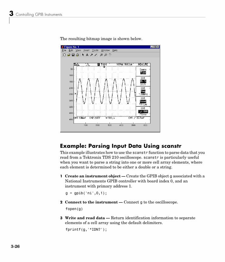
3 Controlling GPIB Instruments
3-26
The resulting bitmap image is shown below.
Example: Parsing Input Data Using scanstrThis example illustrates how to use the scanstr function to parse data that you read from a Tektronix TDS 210 oscilloscope. scanstr is particularly useful when you want to parse a string into one or more cell array elements, where each element is determined to be either a double or a string.
1 Create an instrument object — Create the GPIB object g associated with a National Instruments GPIB controller with board index 0, and an instrument with primary address 1.
g = gpib('ni',0,1);
2 Connect to the instrument — Connect g to the oscilloscope.
fopen(g)
3 Write and read data — Return identification information to separate elements of a cell array using the default delimiters.
fprintf(g,'*IDN?');
Writing and Reading Data
3-27
idn = scanstr(g)idn = 'TEKTRONIX' 'TDS 210' [ 0] 'CF:91.1CT FV:v1.16 TDS2CM:CMV:v1.04'
4 Disconnect and clean up — When you no longer need g, you should disconnect it from the instrument, and remove it from memory and from the MATLAB workspace.
fclose(g)delete(g)clear g
Example: Understanding EOI and EOSThis example illustrates how the EOI line and the EOS character are used to complete read and write operations, and how the EOIMode, EOSMode, and EOSCharCode properties are related to each other. In most cases, you can successfully communicate with your instrument by accepting the default values for these properties.
The default value for EOIMode is on, which means that the EOI line is asserted when the last byte is written to the instrument. The default value for EOSMode is none, which means that the EOSCharCode value is not written to the instrument, and read operations will not complete when the EOSCharCode value is read. Therefore, when you use the default values for EOIMode and EOSMode,
• Write operations complete when the last byte is written to the instrument.
• Read operations complete when the EOI line is asserted by the instrument.
1 Create an instrument object — Create the GPIB object g associated with a National Instruments GPIB controller with board index 0, and an instrument with primary address 1.
g = gpib('ni',0,1);
2 Connect to the instrument — Connect g to the oscilloscope.
fopen(g)
3 Controlling GPIB Instruments
3-28
3 Write and read data — Configure g so that the EOI line is not asserted after the last byte is written to the instrument, and the EOS character is used to complete write operations. The default format for fprintf is %s\n, where \n is replaced by the EOS character as given by EOSCharCode.
g.EOIMode = 'off';g.EOSMode = 'write';fprintf(g,'*IDN?')out = fscanf(g)out =
TEKTRONIX,TDS 210,0,CF:91.1CT FV:v1.16 TDS2CM:CMV:v1.04
Although EOSMode is configured so that read operations will not complete after receiving the EOS character, the preceding read operation succeeded because the EOI line was asserted.
Now configure g so that the EOS character is not used to complete read or write operations. Because the EOI line is not asserted and the EOS character is not written, the instrument cannot interpret the *IDN? command and a timeout occurs.
g.EOSMode = 'none';fprintf(g,'*IDN?')out = fscanf(g)
Warning: GPIB: NI: An I/O operation has been canceled mostly likely due to a timeout.
Now configure g so that the read operation terminates after the “X” character is read. The EOIMode property is configured to on so that the EOI line is asserted after the last byte is written. The EOSMode property is configured to read so that the read operation completes when the EOSCharCode value is read.
g.EOIMode = 'on';g.EOSMode = 'read';g.EOSCharCode = 'X';fprintf(g,'*IDN?')
Writing and Reading Data
3-29
out = fscanf(g)out =
TEKTRONIX
Note that the rest of the identification string remains in the instrument’s hardware buffer. If you do not want to return this data during the next read operation, you should clear it from the instrument buffer with the clrdevice function.
clrdevice(g)
4 Disconnect and clean up — When you no longer need g, you should disconnect it from the instrument, and remove it from memory and from the MATLAB workspace.
fclose(g)delete(g)clear g
3 Controlling GPIB Instruments
3-30
Events and CallbacksYou can enhance the power and flexibility of your instrument control application by using events. An event occurs after a condition is met, and might result in one or more callbacks.
While the instrument object is connected to the instrument, you can use events to display a message, display data, analyze data, and so on. Callbacks are controlled through callback properties and callback functions. All event types have an associated callback property. Callback functions are M-file functions that you construct to suit your specific application needs.
You execute a callback when a particular event occurs by specifying the name of the M-file callback function as the value for the associated callback property.
Example: Introduction to Events and CallbacksThis example uses the M-file callback function instrcallback to display a message to the command line when a bytes-available event occurs. The event is generated when the EOSCharCode property value is read.
g = gpib('ni',0,1);g.BytesAvailableFcnMode = 'eosCharCode';g.BytesAvailableFcn = @instrcallback;fopen(g)fprintf(g,'*IDN?')readasync(g)
The resulting display from instrcallback is shown below.
BytesAvailable event occurred at 17:30:11 for the object: GPIB0-1.
End the GPIB session.
fclose(g)delete(g)clear g
You can use the type command to display instrcallback at the command line.
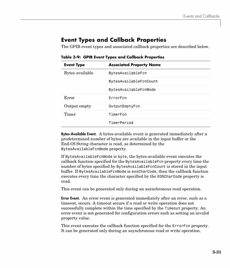
Events and Callbacks
3-31
Event Types and Callback PropertiesThe GPIB event types and associated callback properties are described below.
Bytes-Available Event. A bytes-available event is generated immediately after a predetermined number of bytes are available in the input buffer or the End-Of-String character is read, as determined by the BytesAvailableFcnMode property.
If BytesAvailableFcnMode is byte, the bytes-available event executes the callback function specified for the BytesAvailableFcn property every time the number of bytes specified by BytesAvailableFcnCount is stored in the input buffer. If BytesAvailableFcnMode is eosCharCode, then the callback function executes every time the character specified by the EOSCharCode property is read.
This event can be generated only during an asynchronous read operation.
Error Event. An error event is generated immediately after an error, such as a timeout, occurs. A timeout occurs if a read or write operation does not successfully complete within the time specified by the Timeout property. An error event is not generated for configuration errors such as setting an invalid property value.
This event executes the callback function specified for the ErrorFcn property. It can be generated only during an asynchronous read or write operation.
Table 3-9: GPIB Event Types and Callback Properties
Event Type Associated Property Name
Bytes available BytesAvailableFcn
BytesAvailableFcnCount
BytesAvailableFcnMode
Error ErrorFcn
Output empty OutputEmptyFcn
Timer TimerFcn
TimerPeriod
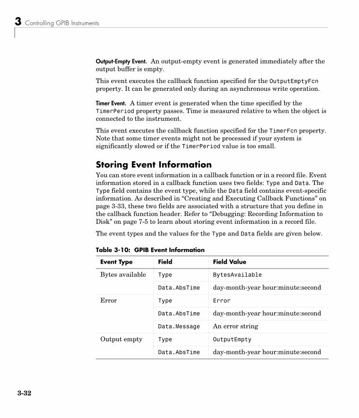
3 Controlling GPIB Instruments
3-32
Output-Empty Event. An output-empty event is generated immediately after the output buffer is empty.
This event executes the callback function specified for the OutputEmptyFcn property. It can be generated only during an asynchronous write operation.
Timer Event. A timer event is generated when the time specified by the TimerPeriod property passes. Time is measured relative to when the object is connected to the instrument.
This event executes the callback function specified for the TimerFcn property. Note that some timer events might not be processed if your system is significantly slowed or if the TimerPeriod value is too small.
Storing Event InformationYou can store event information in a callback function or in a record file. Event information stored in a callback function uses two fields: Type and Data. The Type field contains the event type, while the Data field contains event-specific information. As described in “Creating and Executing Callback Functions” on page 3-33, these two fields are associated with a structure that you define in the callback function header. Refer to “Debugging: Recording Information to Disk” on page 7-5 to learn about storing event information in a record file.
The event types and the values for the Type and Data fields are given below.
Table 3-10: GPIB Event Information
Event Type Field Field Value
Bytes available Type BytesAvailable
Data.AbsTime day-month-year hour:minute:second
Error Type Error
Data.AbsTime day-month-year hour:minute:second
Data.Message An error string
Output empty Type OutputEmpty
Data.AbsTime day-month-year hour:minute:second
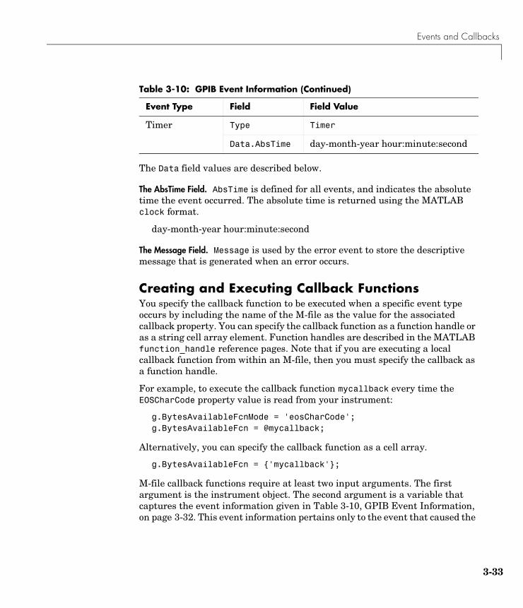
Events and Callbacks
3-33
The Data field values are described below.
The AbsTime Field. AbsTime is defined for all events, and indicates the absolute time the event occurred. The absolute time is returned using the MATLAB clock format.
day-month-year hour:minute:second
The Message Field. Message is used by the error event to store the descriptive message that is generated when an error occurs.
Creating and Executing Callback FunctionsYou specify the callback function to be executed when a specific event type occurs by including the name of the M-file as the value for the associated callback property. You can specify the callback function as a function handle or as a string cell array element. Function handles are described in the MATLAB function_handle reference pages. Note that if you are executing a local callback function from within an M-file, then you must specify the callback as a function handle.
For example, to execute the callback function mycallback every time the EOSCharCode property value is read from your instrument:
g.BytesAvailableFcnMode = 'eosCharCode';g.BytesAvailableFcn = @mycallback;
Alternatively, you can specify the callback function as a cell array.
g.BytesAvailableFcn = {'mycallback'};
M-file callback functions require at least two input arguments. The first argument is the instrument object. The second argument is a variable that captures the event information given in Table 3-10, GPIB Event Information, on page 3-32. This event information pertains only to the event that caused the
Timer Type Timer
Data.AbsTime day-month-year hour:minute:second
Table 3-10: GPIB Event Information (Continued)
Event Type Field Field Value
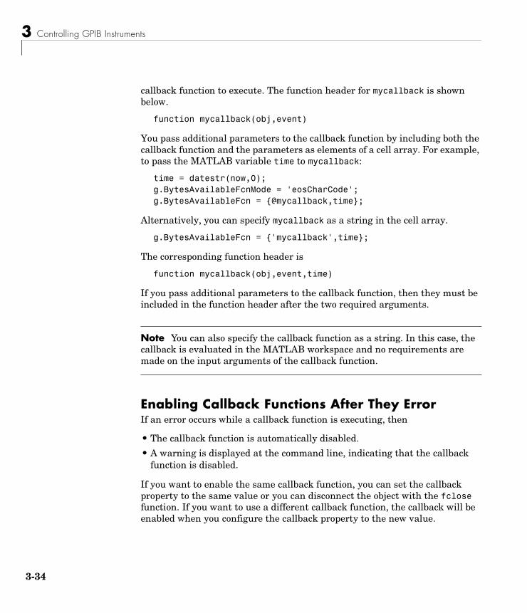
3 Controlling GPIB Instruments
3-34
callback function to execute. The function header for mycallback is shown below.
function mycallback(obj,event)
You pass additional parameters to the callback function by including both the callback function and the parameters as elements of a cell array. For example, to pass the MATLAB variable time to mycallback:
time = datestr(now,0);g.BytesAvailableFcnMode = 'eosCharCode';g.BytesAvailableFcn = {@mycallback,time};
Alternatively, you can specify mycallback as a string in the cell array.
g.BytesAvailableFcn = {'mycallback',time};
The corresponding function header is
function mycallback(obj,event,time)
If you pass additional parameters to the callback function, then they must be included in the function header after the two required arguments.
Note You can also specify the callback function as a string. In this case, the callback is evaluated in the MATLAB workspace and no requirements are made on the input arguments of the callback function.
Enabling Callback Functions After They ErrorIf an error occurs while a callback function is executing, then
• The callback function is automatically disabled.
• A warning is displayed at the command line, indicating that the callback function is disabled.
If you want to enable the same callback function, you can set the callback property to the same value or you can disconnect the object with the fclose function. If you want to use a different callback function, the callback will be enabled when you configure the callback property to the new value.
Events and Callbacks
3-35
Example: Using Events and Callbacks to Read Binary DataThis example extends “Example: Reading Binary Data” on page 3-24 by using the M-file callback function instrcallback to display event-related information to the command line when a bytes-available event occurs during a binary read operation.
1 Create an instrument object — Create the GPIB object g associated with a National Instruments GPIB controller with board index 0, and an instrument with primary address 1.
g = gpib('ni',0,1);
2 Configure properties — Configure the input buffer to accept a reasonably large number of bytes, and configure the timeout value to two minutes to account for slow data transfer.
g.InputBufferSize = 50000;g.Timeout = 120;
Configure g to execute the callback function instrcallback every time 5000 bytes is stored in the input buffer. Because instrcallback requires an instrument object and event information to be passed as input arguments, the callback function is specified as a function handle.
g.BytesAvailableFcnMode = 'byte';g.BytesAvailableFcnCount = 5000;g.BytesAvailableFcn = @instrcallback;
3 Connect to the instrument — Connect g to the oscilloscope.
fopen(g)
4 Write and read data — Configure the scope to transfer the screen display as a bitmap.
fprintf(g,'HARDCOPY:PORT GPIB')fprintf(g,'HARDCOPY:FORMAT BMP')fprintf(g,'HARDCOPY START')
Initiate the asynchronous read operation, and begin generating events.
readasync(g)
3 Controlling GPIB Instruments
3-36
instrcallback is called every time 5000 bytes is stored in the input buffer. The resulting displays are shown below.
BytesAvailable event occurred at 09:41:42 for the object: GPIB0-1.BytesAvailable event occurred at 09:41:50 for the object: GPIB0-1.BytesAvailable event occurred at 09:41:58 for the object: GPIB0-1.BytesAvailable event occurred at 09:42:06 for the object: GPIB0-1.BytesAvailable event occurred at 09:42:14 for the object: GPIB0-1.BytesAvailable event occurred at 09:42:22 for the object: GPIB0-1.BytesAvailable event occurred at 09:42:30 for the object: GPIB0-1.
Wait until all the data is sent to the input buffer, and then transfer the data to MATLAB as unsigned 8-bit integers.
g.TransferStatusans =idleout = fread(g,g.BytesAvailable,'uint8');
5 Disconnect and clean up — When you no longer need g, you should disconnect it from the instrument, and remove it from memory and from the MATLAB workspace.
fclose(g)delete(g)clear g
Triggers
3-37
TriggersYou can execute a trigger with the trigger function. This function is equivalent to writing the GET (Group Execute Trigger) GPIB command to the instrument.
trigger instructs all the addressed Listeners to perform some instrument-specific function such as taking a measurement. Refer to your instrument documentation to learn how to use its triggering capabilities.
Example: Executing a TriggerThis example illustrates GPIB triggering using an Agilent 33120A function generator. The output of the function generator is displayed with an oscilloscope so that the trigger can be observed.
1 Create an instrument object — Create the GPIB object g associated with a National Instruments GPIB controller with board index 0, and an instrument with primary address 1.
g = gpib('ni',0,1);
2 Connect to the instrument — Connect g to the function generator.
fopen(g)
3 Write and read data — Configure the function generator to produce a 5000 Hz sine wave, with 6 volts peak-to-peak.
fprintf(g,'Func:Shape Sin')fprintf(g,'Volt 3')fprintf(g,'Freq 5000')
Configure the burst of the trigger to display the sine wave for five seconds, configure the function generator to expect the trigger from the GPIB board, and enable the burst mode.
fprintf(g,'BM:NCycles 25000')fprintf(g,'Trigger:Source Bus')fprintf(g,'BM:State On')
Trigger the instrument.
trigger(g)
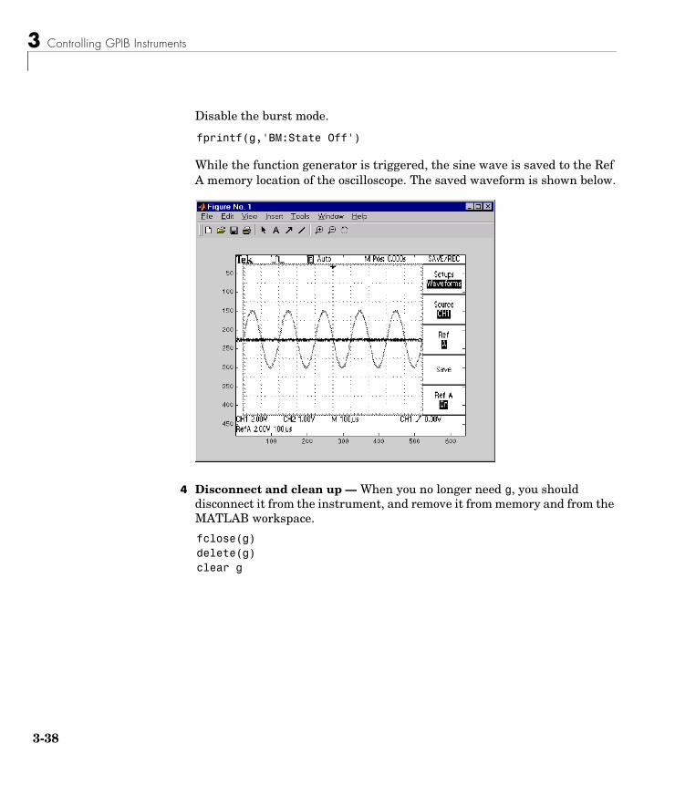
3 Controlling GPIB Instruments
3-38
Disable the burst mode.
fprintf(g,'BM:State Off')
While the function generator is triggered, the sine wave is saved to the Ref A memory location of the oscilloscope. The saved waveform is shown below.
4 Disconnect and clean up — When you no longer need g, you should disconnect it from the instrument, and remove it from memory and from the MATLAB workspace.
fclose(g)delete(g)clear g
Serial Polls
3-39
Serial PollsYou can execute a serial poll with the spoll function. In a serial poll, the Controller asks (polls) each addressed Listener to send back a status byte that indicates whether it has asserted the SRQ line and needs servicing. The seventh bit of this byte (the RQS bit) is set if the instrument is requesting service.
The Controller performs the following steps for every addressed Listener:
1 The Listener is addressed to talk and the Serial Poll Enable (SPE) command byte is sent.
2 The ATN line is set high and the Listener returns the status byte.
3 The ATN line is set low and the Serial Poll Disable (SPD) command byte is sent to end the poll sequence.
Refer to “Status and Event Reporting” on page 3-9 for more information on the GPIB bus lines and the RQS bit.
Example: Executing a Serial PollThis example shows you how to execute a serial poll for a Agilent 33120A function generator, and a Tektronix TDS 210 oscilloscope. In doing so, the example shows you how to configure many of the status bits described in “The Standard Event Status Register” on page 3-12.
1 Create instrument objects — Create a GPIB object associated with a Agilent 33120A function generator at primary address 1.
g1 = gpib('ni',0,1);
Create a GPIB object associated with a Tektronix TDS 210 oscilloscope at primary address 2.
g2 = gpib('ni',0,2);
2 Connect to the instrument — Connect g1 to the function generator and connect g2 to the oscilloscope.
fopen([g1 g2])
3 Controlling GPIB Instruments
3-40
3 Configure property values — Configure both objects to time out after 1 second.
set([g1 g2],'Timeout',1)
4 Write and read data — Configure the function generator to request service when a command error occurs.
fprintf(g1,'*CLS'); fprintf(g1,'*ESE 32'); fprintf(g1,'*SRE 32');
Configure the oscilloscope to request service when a command error occurs.
fprintf(g2,'*CLS') fprintf(g2,'*PSC 0') fprintf(g2,'*ESE 32') fprintf(g2,'DESE 32') fprintf(g2,'*SRE 32')
Determine if any instrument needs servicing.
spoll([g1 g2])ans =[]
Query the voltage value for each instrument.
fprintf(g1,'Volt?') fprintf(g2,'Volt?')
Determine if either instrument produced an error due to the preceding query.
out = spoll([g1 g2]);
Because Volt? is an invalid command for the oscilloscope, it is requesting service.
out == [g1 g2]ans =0 1
Serial Polls
3-41
Because Volt? is a valid command for the function generator, the value is read back successfully.
volt1 = fscanf(g1)volt1 =+1.00000E-01
However, the oscilloscope read operation times out after 1 second.
volt2 = fscanf(g2) Warning: GPIB: NI: An I/O operation has been canceled, most likely due to a timeout.
volt2 =''
5 Disconnect and clean up — When you no longer need g1 and g2, you should disconnect them from the instruments, and remove them from memory and from the MATLAB workspace.
fclose([g1 g2])delete([g1 g2])clear g1 g2

3 Controlling GPIB Instruments
3-42
4Controlling Instruments Using the VISA Standard
This chapter describes specific issues related to controlling instruments that use the VISA standard. The sections are as follows.
VISA Overview (p. 4-2) Brief description of the Virtual Instrument Standard Architecture (VISA) standard.
The GPIB Interface (p. 4-5) The VISA-GPIB object establishes a connection between MATLAB and the instrument via its GPIB interface.
The VXI Interface (p. 4-9) The VISA-VXI object establishes a connection between MATLAB and the instrument via its VXI interface.
The GPIB-VXI Interface (p. 4-21)
The VISA-GPIB-VXI object establishes a connection between MATLAB and the instrument via its GPIB-VXI interface.
The Serial Port Interface (p. 4-26)
The VISA serial object establishes a connection between MATLAB and the instrument via the serial port.
4 Controlling Instruments Using the VISA Standard
4-2
VISA OverviewVirtual Instrument Standard Architecture (VISA) is a standard defined by Agilent Technologies and National Instruments for communicating with instruments regardless of the interface.
The Instrument Control Toolbox supports the GPIB, VXI, GPIB-VXI, and serial port interfaces using the VISA standard. Communication is established through a VISA instrument object, which you create in the MATLAB workspace. For example, a VISA-GPIB object allows you to use the VISA standard to communicate with an instrument that possesses a GPIB interface.
Note Most features associated with VISA instrument objects are identical to the features associated with GPIB and serial port objects. Therefore, this chapter presents only interface-specific functions and properties. For example, register-based communication is discussed for VISA-VXI objects, but message-based communication is not discussed as this topic is covered elsewhere in this guide.
For many VISA applications, you can communicate with your instrument without detailed knowledge of how the interface works. In this case, you might want to begin with one of these topics:
• “The GPIB Interface” on page 4-5
• “The VXI Interface” on page 4-9
• “The GPIB-VXI Interface” on page 4-21
• “The Serial Port Interface” on page 4-26
If you want a high-level description of all the steps you are likely to take when communicating with your instrument, refer to Chapter 2, “The Instrument Control Session.”
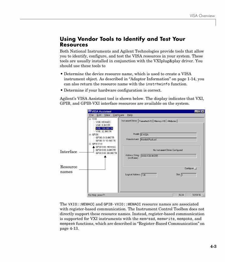
VISA Overview
4-3
Using Vendor Tools to Identify and Test Your ResourcesBoth National Instruments and Agilent Technologies provide tools that allow you to identify, configure, and test the VISA resources in your system. These tools are usually installed in conjunction with the VXIplug&play driver. You should use these tools to
• Determine the device resource name, which is used to create a VISA instrument object. As described in “Adaptor Information” on page 1-14, you can also return the resource name with the instrhwinfo function.
• Determine if your hardware configuration is correct.
Agilent’s VISA Assistant tool is shown below. The display indicates that VXI, GPIB, and GPIB-VXI interface resources are available on the system.
The VXI0::MEMACC and GPIB-VXI0::MEMACC resource names are associated with register-based communication. The Instrument Control Toolbox does not directly support these resource names. Instead, register-based communication is supported for VXI instruments with the memread, memwrite, mempoke, and mempeek functions, which are described in “Register-Based Communication” on page 4-13.
Resource names
Interface
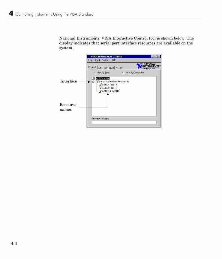
4 Controlling Instruments Using the VISA Standard
4-4
National Instruments’ VISA Interactive Control tool is shown below. The display indicates that serial port interface resources are available on the system.
Resource names
Interface
The GPIB Interface
4-5
The GPIB InterfaceThe GPIB interface is supported through a VISA-GPIB object. The features associated with a VISA-GPIB object are similar to the features associated with a GPIB object. Therefore, only functions and properties that are unique to VISA’s GPIB interface are discussed in this section. These unique features are associated with
• Creating a VISA-GPIB object
• The VISA-GPIB address
Refer to Chapter 3, “Controlling GPIB Instruments” to learn about the GPIB interface, writing and reading text and binary data, using events and callbacks, using triggers, and so on.
Note The VISA-GPIB object does not support the spoll function, or the BusManagementStatus, CompareBits, and HandshakeStatus properties.
Creating a VISA-GPIB ObjectYou create a VISA-GPIB object with the visa function. Each VISA-GPIB object is associated with
• A GPIB controller installed in your computer
• An instrument with a GPIB interface
visa requires the vendor name and the resource name as input arguments. The vendor name can be agilent, ni, or tek. The resource name consists of the GPIB board index, the instrument primary address, and the instrument secondary address. You can find the VISA-GPIB resource name for a given instrument with the configuration tool provided by your vendor, or with the instrhwinfo function. As described in “Configuring Properties During Object Creation” on page 2-3, you can also configure properties during object creation.
For example, to create a VISA-GPIB object associated with a National Instruments controller with board index 0, and a Tektronix TDS 210 digital oscilloscope with primary address 1 and secondary address 0:
vg = visa('ni','GPIB0::1::0::INSTR');
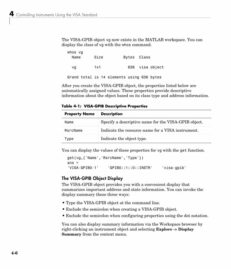
4 Controlling Instruments Using the VISA Standard
4-6
The VISA-GPIB object vg now exists in the MATLAB workspace. You can display the class of vg with the whos command.
whos vg Name Size Bytes Class
vg 1x1 636 visa object
Grand total is 14 elements using 636 bytes
After you create the VISA-GPIB object, the properties listed below are automatically assigned values. These properties provide descriptive information about the object based on its class type and address information.
You can display the values of these properties for vg with the get function.
get(vg,{'Name','RsrcName','Type'})ans = 'VISA-GPIB0-1' 'GPIB0::1::0::INSTR' 'visa-gpib'
The VISA-GPIB Object DisplayThe VISA-GPIB object provides you with a convenient display that summarizes important address and state information. You can invoke the display summary these three ways:
• Type the VISA-GPIB object at the command line.
• Exclude the semicolon when creating a VISA-GPIB object.
• Exclude the semicolon when configuring properties using the dot notation.
You can also display summary information via the Workspace browser by right-clicking an instrument object and selecting Explore -> Display Summary from the context menu.
Table 4-1: VISA-GPIB Descriptive Properties
Property Name Description
Name Specify a descriptive name for the VISA-GPIB object.
RsrcName Indicate the resource name for a VISA instrument.
Type Indicate the object type.
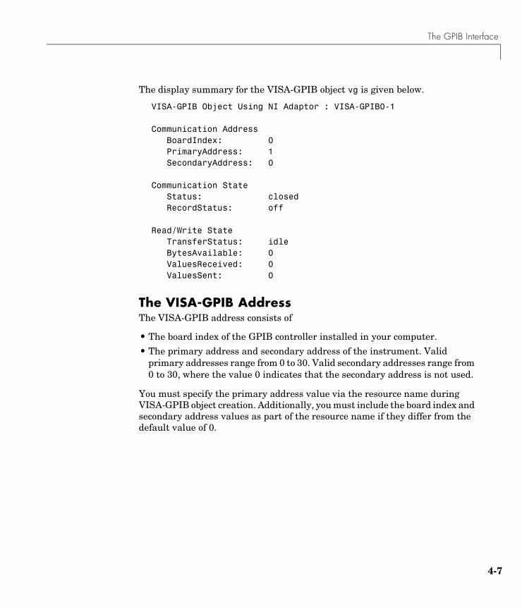
The GPIB Interface
4-7
The display summary for the VISA-GPIB object vg is given below.
VISA-GPIB Object Using NI Adaptor : VISA-GPIB0-1
Communication Address BoardIndex: 0PrimaryAddress: 1SecondaryAddress: 0
Communication State Status: closedRecordStatus: off
Read/Write State TransferStatus: idleBytesAvailable: 0ValuesReceived: 0ValuesSent: 0
The VISA-GPIB AddressThe VISA-GPIB address consists of
• The board index of the GPIB controller installed in your computer.
• The primary address and secondary address of the instrument. Valid primary addresses range from 0 to 30. Valid secondary addresses range from 0 to 30, where the value 0 indicates that the secondary address is not used.
You must specify the primary address value via the resource name during VISA-GPIB object creation. Additionally, you must include the board index and secondary address values as part of the resource name if they differ from the default value of 0.
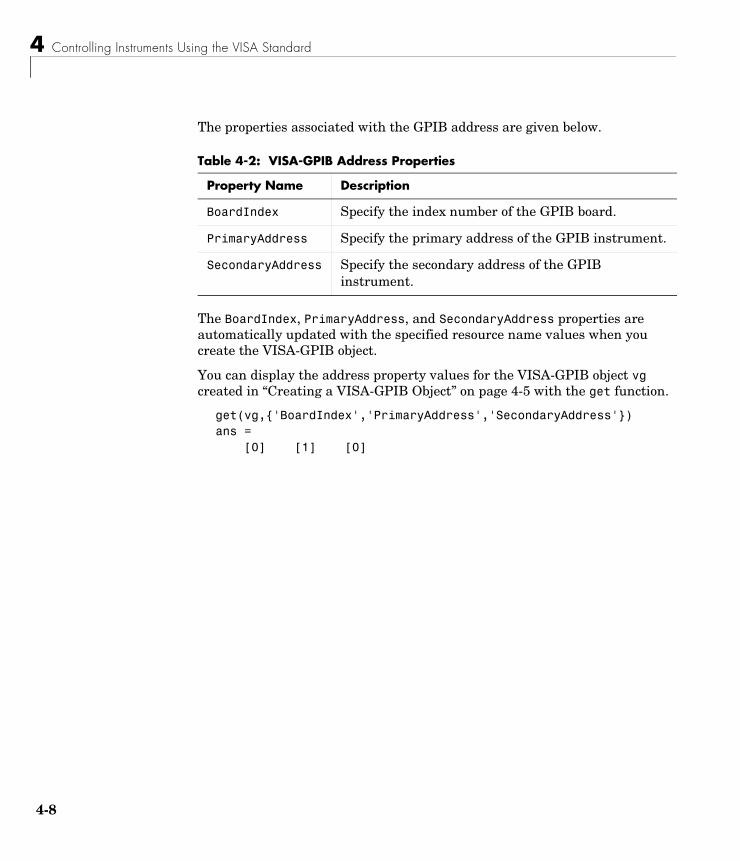
4 Controlling Instruments Using the VISA Standard
4-8
The properties associated with the GPIB address are given below.
The BoardIndex, PrimaryAddress, and SecondaryAddress properties are automatically updated with the specified resource name values when you create the VISA-GPIB object.
You can display the address property values for the VISA-GPIB object vg created in “Creating a VISA-GPIB Object” on page 4-5 with the get function.
get(vg,{'BoardIndex','PrimaryAddress','SecondaryAddress'})ans = [0] [1] [0]
Table 4-2: VISA-GPIB Address Properties
Property Name Description
BoardIndex Specify the index number of the GPIB board.
PrimaryAddress Specify the primary address of the GPIB instrument.
SecondaryAddress Specify the secondary address of the GPIB instrument.
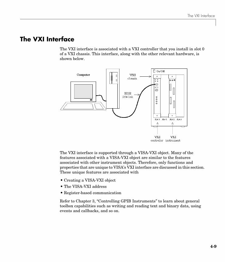
The VXI Interface
4-9
The VXI InterfaceThe VXI interface is associated with a VXI controller that you install in slot 0 of a VXI chassis. This interface, along with the other relevant hardware, is shown below.
The VXI interface is supported through a VISA-VXI object. Many of the features associated with a VISA-VXI object are similar to the features associated with other instrument objects. Therefore, only functions and properties that are unique to VISA’s VXI interface are discussed in this section. These unique features are associated with
• Creating a VISA-VXI object
• The VISA-VXI address
• Register-based communication
Refer to Chapter 3, “Controlling GPIB Instruments” to learn about general toolbox capabilities such as writing and reading text and binary data, using events and callbacks, and so on.
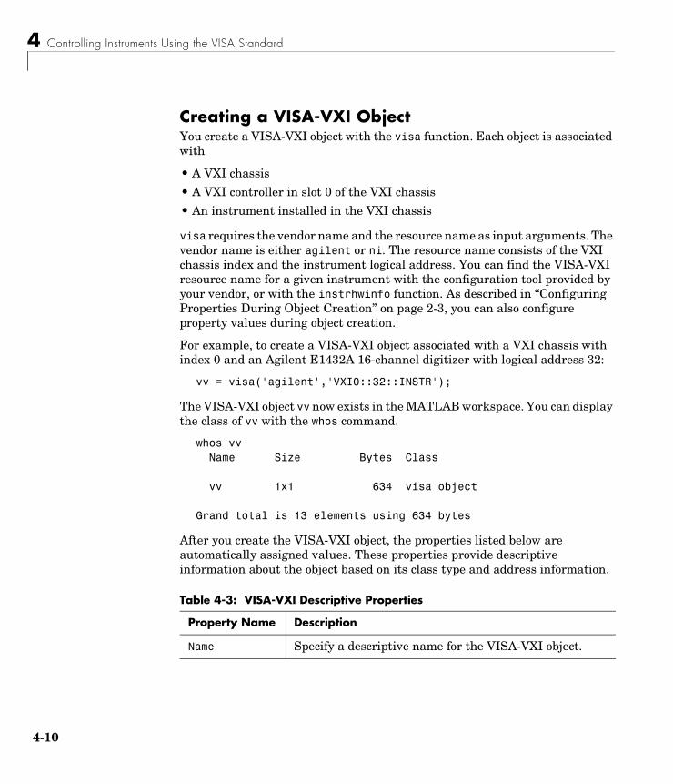
4 Controlling Instruments Using the VISA Standard
4-10
Creating a VISA-VXI ObjectYou create a VISA-VXI object with the visa function. Each object is associated with
• A VXI chassis
• A VXI controller in slot 0 of the VXI chassis
• An instrument installed in the VXI chassis
visa requires the vendor name and the resource name as input arguments. The vendor name is either agilent or ni. The resource name consists of the VXI chassis index and the instrument logical address. You can find the VISA-VXI resource name for a given instrument with the configuration tool provided by your vendor, or with the instrhwinfo function. As described in “Configuring Properties During Object Creation” on page 2-3, you can also configure property values during object creation.
For example, to create a VISA-VXI object associated with a VXI chassis with index 0 and an Agilent E1432A 16-channel digitizer with logical address 32:
vv = visa('agilent','VXI0::32::INSTR');
The VISA-VXI object vv now exists in the MATLAB workspace. You can display the class of vv with the whos command.
whos vv Name Size Bytes Class
vv 1x1 634 visa object
Grand total is 13 elements using 634 bytes
After you create the VISA-VXI object, the properties listed below are automatically assigned values. These properties provide descriptive information about the object based on its class type and address information.
Table 4-3: VISA-VXI Descriptive Properties
Property Name Description
Name Specify a descriptive name for the VISA-VXI object.
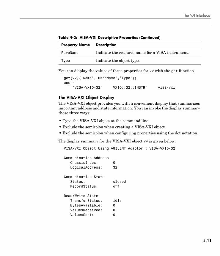
The VXI Interface
4-11
You can display the values of these properties for vv with the get function.
get(vv,{'Name','RsrcName','Type'})ans = 'VISA-VXI0-32' 'VXI0::32::INSTR' 'visa-vxi'
The VISA-VXI Object DisplayThe VISA-VXI object provides you with a convenient display that summarizes important address and state information. You can invoke the display summary these three ways:
• Type the VISA-VXI object at the command line.
• Exclude the semicolon when creating a VISA-VXI object.
• Exclude the semicolon when configuring properties using the dot notation.
The display summary for the VISA-VXI object vv is given below.
VISA-VXI Object Using AGILENT Adaptor : VISA-VXI0-32
Communication Address ChassisIndex: 0LogicalAddress: 32
Communication State Status: closedRecordStatus: off
Read/Write State TransferStatus: idleBytesAvailable: 0ValuesReceived: 0ValuesSent: 0
RsrcName Indicate the resource name for a VISA instrument.
Type Indicate the object type.
Table 4-3: VISA-VXI Descriptive Properties (Continued)
Property Name Description
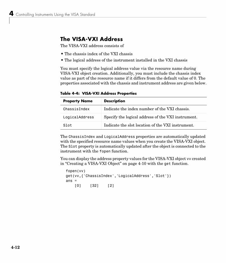
4 Controlling Instruments Using the VISA Standard
4-12
The VISA-VXI AddressThe VISA-VXI address consists of
• The chassis index of the VXI chassis
• The logical address of the instrument installed in the VXI chassis
You must specify the logical address value via the resource name during VISA-VXI object creation. Additionally, you must include the chassis index value as part of the resource name if it differs from the default value of 0. The properties associated with the chassis and instrument address are given below.
The ChassisIndex and LogicalAddress properties are automatically updated with the specified resource name values when you create the VISA-VXI object. The Slot property is automatically updated after the object is connected to the instrument with the fopen function.
You can display the address property values for the VISA-VXI object vv created in “Creating a VISA-VXI Object” on page 4-10 with the get function.
fopen(vv)get(vv,{'ChassisIndex','LogicalAddress','Slot'})ans = [0] [32] [2]
Table 4-4: VISA-VXI Address Properties
Property Name Description
ChassisIndex Indicate the index number of the VXI chassis.
LogicalAddress Specify the logical address of the VXI instrument.
Slot Indicate the slot location of the VXI instrument.

The VXI Interface
4-13
Register-Based CommunicationVXI instruments are either message-based or register-based. Generally, it is assumed that message-based instruments are easier to use, while register-based instruments are faster. A message-based instrument has its own processor that allows it to interpret high-level commands such as a SCPI command. Therefore, to communicate with a message-based instrument, you can use the read and write functions fscanf, fread, fprintf, and fwrite. For detailed information about these functions, refer to “Writing and Reading Data” on page 2-12.
If the message-based instrument also contains shared memory, then you can access the shared memory through register-based read and write operations. A register-based instrument usually does not have its own processor to interpret high-level commands. Therefore, to communicate with a register-based instrument, you need to use read and write functions that access the register.
There are two types of register-based write and read functions: low-level and high-level. The main advantage of the high-level functions is ease of use. Refer to “Example: Using High-Level Memory Functions” on page 4-16 for more information. The main advantage of the low-level functions is speed. Refer to “Example: Using Low-Level Memory Functions” on page 4-18 for more information.
The functions associated with register-based write and read operations are given below.
Table 4-5: VISA-VXI Register-Based Write and Read Functions
Function Name Description
memmap Map memory for low-level memory read and write operations.
mempeek Low-level memory read from VXI register.
mempoke Low-level memory write to VXI register.
memread High-level memory read from VXI register.
memunmap Unmap memory for low-level memory read and write operations.
memwrite High-level memory write to VXI register.
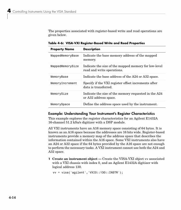
4 Controlling Instruments Using the VISA Standard
4-14
The properties associated with register-based write and read operations are given below.
Example: Understanding Your Instrument’s Register CharacteristicsThis example explores the register characteristics for an Agilent E1432A 16-channel 51.2 kSa/s digitizer with a DSP module.
All VXI instruments have an A16 memory space consisting of 64 bytes. It is known as an A16 space because the addresses are 16 bits wide. Register-based instruments provide a memory map of the address space that describes the information contained within the A16 space. Some VXI instruments also have an A24 or A32 space if the 64 bytes provided by the A16 space are not enough to perform the necessary tasks. A VXI instrument cannot use both the A24 and A32 space.
1 Create an instrument object — Create the VISA-VXI object vv associated with a VXI chassis with index 0, and an Agilent E1432A digitizer with logical address 130.
vv = visa('agilent','VXI0::130::INSTR');
Table 4-6: VISA-VXI Register-Based Write and Read Properties
Property Name Description
MappedMemoryBase Indicate the base memory address of the mapped memory.
MappedMemorySize Indicate the size of the mapped memory for low-level read and write operations.
MemoryBase Indicate the base address of the A24 or A32 space.
MemoryIncrement Specify if the VXI register offset increments after data is transferred.
MemorySize Indicate the size of the memory requested in the A24 or A32 address space.
MemorySpace Define the address space used by the instrument.
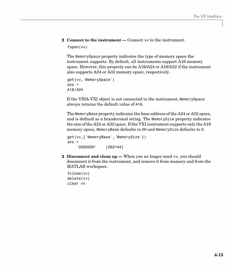
The VXI Interface
4-15
2 Connect to the instrument — Connect vv to the instrument.
fopen(vv)
The MemorySpace property indicates the type of memory space the instrument supports. By default, all instruments support A16 memory space. However, this property can be A16/A24 or A16/A32 if the instrument also supports A24 or A32 memory space, respectively.
get(vv,'MemorySpace')ans =A16/A24
If the VISA-VXI object is not connected to the instrument, MemorySpace always returns the default value of A16.
The MemoryBase property indicates the base address of the A24 or A32 space, and is defined as a hexadecimal string. The MemorySize property indicates the size of the A24 or A32 space. If the VXI instrument supports only the A16 memory space, MemoryBase defaults to 0H and MemorySize defaults to 0.
get(vv,{'MemoryBase','MemorySize'})ans = '200000H' [262144]
3 Disconnect and clean up — When you no longer need vv, you should disconnect it from the instrument, and remove it from memory and from the MATLAB workspace.
fclose(vv)delete(vv)clear vv
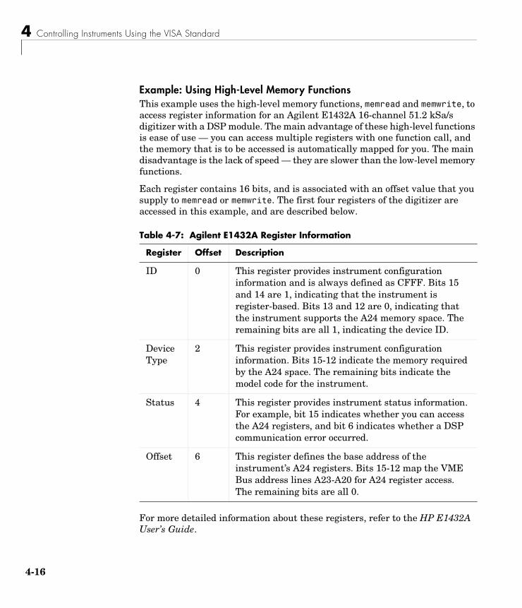
4 Controlling Instruments Using the VISA Standard
4-16
Example: Using High-Level Memory FunctionsThis example uses the high-level memory functions, memread and memwrite, to access register information for an Agilent E1432A 16-channel 51.2 kSa/s digitizer with a DSP module. The main advantage of these high-level functions is ease of use — you can access multiple registers with one function call, and the memory that is to be accessed is automatically mapped for you. The main disadvantage is the lack of speed — they are slower than the low-level memory functions.
Each register contains 16 bits, and is associated with an offset value that you supply to memread or memwrite. The first four registers of the digitizer are accessed in this example, and are described below.
For more detailed information about these registers, refer to the HP E1432A User’s Guide.
Table 4-7: Agilent E1432A Register Information
Register Offset Description
ID 0 This register provides instrument configuration information and is always defined as CFFF. Bits 15 and 14 are 1, indicating that the instrument is register-based. Bits 13 and 12 are 0, indicating that the instrument supports the A24 memory space. The remaining bits are all 1, indicating the device ID.
Device Type
2 This register provides instrument configuration information. Bits 15-12 indicate the memory required by the A24 space. The remaining bits indicate the model code for the instrument.
Status 4 This register provides instrument status information. For example, bit 15 indicates whether you can access the A24 registers, and bit 6 indicates whether a DSP communication error occurred.
Offset 6 This register defines the base address of the instrument’s A24 registers. Bits 15-12 map the VME Bus address lines A23-A20 for A24 register access. The remaining bits are all 0.
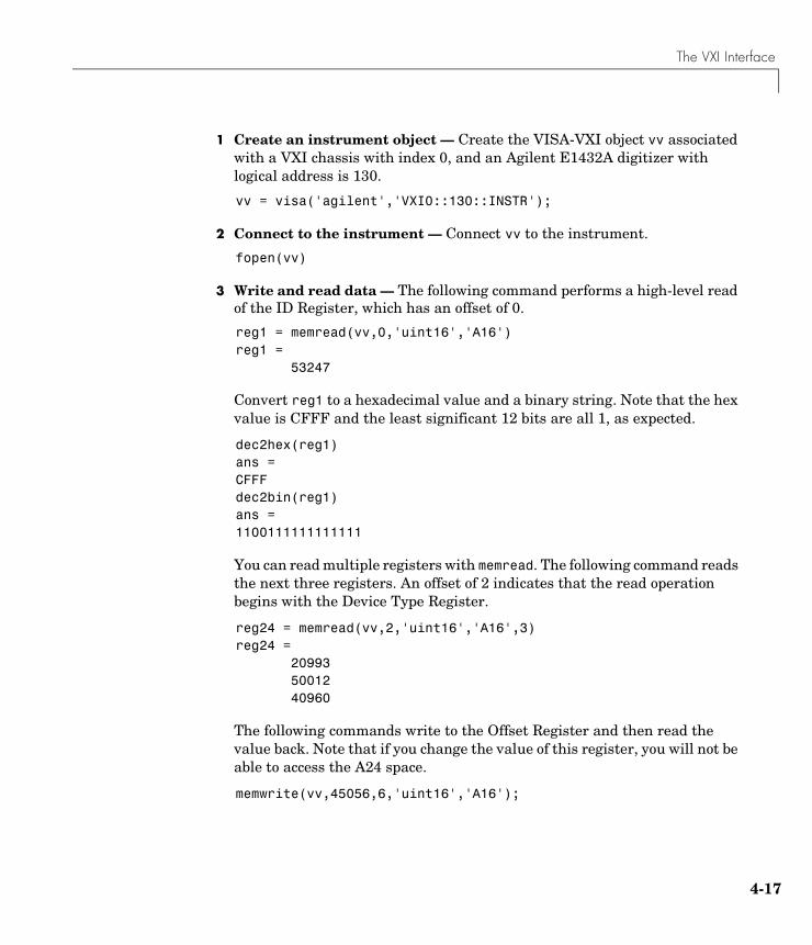
The VXI Interface
4-17
1 Create an instrument object — Create the VISA-VXI object vv associated with a VXI chassis with index 0, and an Agilent E1432A digitizer with logical address is 130.
vv = visa('agilent','VXI0::130::INSTR');
2 Connect to the instrument — Connect vv to the instrument.
fopen(vv)
3 Write and read data — The following command performs a high-level read of the ID Register, which has an offset of 0.
reg1 = memread(vv,0,'uint16','A16')reg1 = 53247
Convert reg1 to a hexadecimal value and a binary string. Note that the hex value is CFFF and the least significant 12 bits are all 1, as expected.
dec2hex(reg1)ans =CFFFdec2bin(reg1)ans =1100111111111111
You can read multiple registers with memread. The following command reads the next three registers. An offset of 2 indicates that the read operation begins with the Device Type Register.
reg24 = memread(vv,2,'uint16','A16',3)reg24 = 20993 50012 40960
The following commands write to the Offset Register and then read the value back. Note that if you change the value of this register, you will not be able to access the A24 space.
memwrite(vv,45056,6,'uint16','A16');
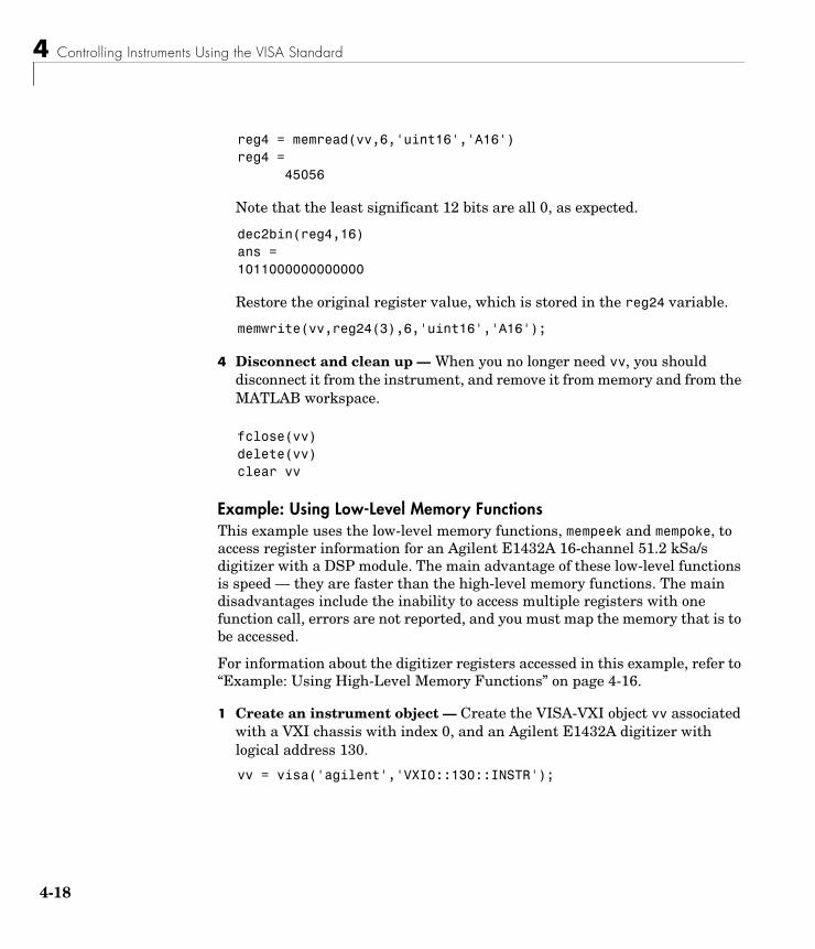
4 Controlling Instruments Using the VISA Standard
4-18
reg4 = memread(vv,6,'uint16','A16')reg4 =
45056
Note that the least significant 12 bits are all 0, as expected.
dec2bin(reg4,16)ans =1011000000000000
Restore the original register value, which is stored in the reg24 variable.
memwrite(vv,reg24(3),6,'uint16','A16');
4 Disconnect and clean up — When you no longer need vv, you should disconnect it from the instrument, and remove it from memory and from the MATLAB workspace.
fclose(vv)delete(vv)clear vv
Example: Using Low-Level Memory FunctionsThis example uses the low-level memory functions, mempeek and mempoke, to access register information for an Agilent E1432A 16-channel 51.2 kSa/s digitizer with a DSP module. The main advantage of these low-level functions is speed — they are faster than the high-level memory functions. The main disadvantages include the inability to access multiple registers with one function call, errors are not reported, and you must map the memory that is to be accessed.
For information about the digitizer registers accessed in this example, refer to “Example: Using High-Level Memory Functions” on page 4-16.
1 Create an instrument object — Create the VISA-VXI object vv associated with a VXI chassis with index 0, and an Agilent E1432A digitizer with logical address 130.
vv = visa('agilent','VXI0::130::INSTR');
The VXI Interface
4-19
2 Connect to the instrument — Connect vv to the instrument.
fopen(vv)
3 Write and read data — Before you can use the low-level memory functions, you must first map the memory space with the memmap function. If the memory requested by memmap does not exist, an error is returned. The following command maps the first 16 registers of the A16 memory space.
memmap(vv,'A16',0,16);
The MappedMemoryBase and MappedMemorySize properties indicate if memory has been mapped. MappedMemoryBase is the base address of the mapped memory and is defined as a hexadecimal string. MappedMemorySize is the size of the mapped memory. These properties are similar to the MemoryBase and MemorySize properties that describe the A24 or A32 memory space.
get(vv,{'MappedMemoryBase','MappedMemorySize'})ans = '16737610H' [16]
The following command performs a low-level read of the ID Register, which has an offset of 0.
reg1 = mempeek(vv,0,'uint16')reg1 = 53247
The following command performs a low-level read of the Offset Register, which has an offset of 6.
reg4 = mempeek(vv,6,'uint16')reg4 = 40960
The following commands write to the Offset Register and then read the value back. Note that if you change the value of this register, you will not be able to access the A24 space.
mempoke(vv,45056,6,'uint16');
4 Controlling Instruments Using the VISA Standard
4-20
mempeek(vv,6,'uint16')ans = 45056
Restore the original register value.
mempoke(vv,reg4,6,'uint16');
When you have finished accessing the registers, you should unmap the memory with the memunmap function.
memunmap(vv)get(vv,{'MappedMemoryBase','MappedMemorySize'})ans = '0H' [0]
If memory is still mapped when the object is disconnected from the instrument, the memory is automatically unmapped for you.
4 Disconnect and clean up — When you no longer need vv, you should disconnect it from the instrument, and remove it from memory and from the MATLAB workspace.
fclose(vv)delete(vv)clear vv
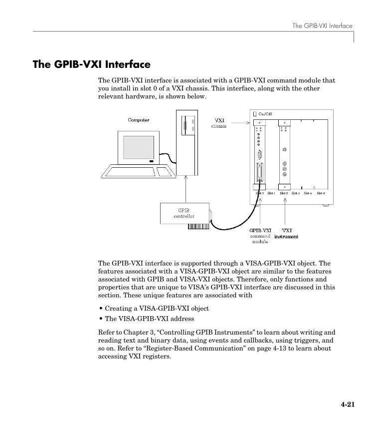
The GPIB-VXI Interface
4-21
The GPIB-VXI InterfaceThe GPIB-VXI interface is associated with a GPIB-VXI command module that you install in slot 0 of a VXI chassis. This interface, along with the other relevant hardware, is shown below.
The GPIB-VXI interface is supported through a VISA-GPIB-VXI object. The features associated with a VISA-GPIB-VXI object are similar to the features associated with GPIB and VISA-VXI objects. Therefore, only functions and properties that are unique to VISA’s GPIB-VXI interface are discussed in this section. These unique features are associated with
• Creating a VISA-GPIB-VXI object
• The VISA-GPIB-VXI address
Refer to Chapter 3, “Controlling GPIB Instruments” to learn about writing and reading text and binary data, using events and callbacks, using triggers, and so on. Refer to “Register-Based Communication” on page 4-13 to learn about accessing VXI registers.
4 Controlling Instruments Using the VISA Standard
4-22
Note The VISA-GPIB-VXI object does not support the spoll and trigger functions, or the BusManagementStatus, HandshakeStatus, InterruptFcn, TriggerFcn, TriggerLine, and TriggerType properties.
Creating a VISA-GPIB-VXI ObjectYou create a VISA-GPIB-VXI object with the visa function. As shown in the preceding figure, each object is associated with
• A GPIB controller installed in your computer
• A VXI chassis
• A GPIB-VXI command module in slot 0 of the VXI chassis
• An instrument installed in the VXI chassis
visa requires the vendor name and the resource name as input arguments. The vendor name is either agilent or ni. The resource name consists of the VXI chassis index and the instrument logical address. You can find the VISA-GPIB-VXI resource name for a given instrument with the configuration tool provided by your vendor, or with the instrhwinfo function. As described in “Configuring Properties During Object Creation” on page 2-3, you can also configure property values during object creation.
For example, to create a VISA-GPIB-VXI object associated with a VXI chassis with index 0, an Agilent E1406A Command Module in slot 0, and an Agilent E1441A Arbitrary Waveform Generator in slot 2 with logical address 80:
vgv = visa('agilent','GPIB-VXI0::80::INSTR');
The VISA-GPIB-VXI object vgv now exists in the MATLAB workspace. You can display the class of vgv with the whos command.
whos vgv Name Size Bytes Class
vgv 1x1 644 visa object
Grand total is 18 elements using 644 bytes
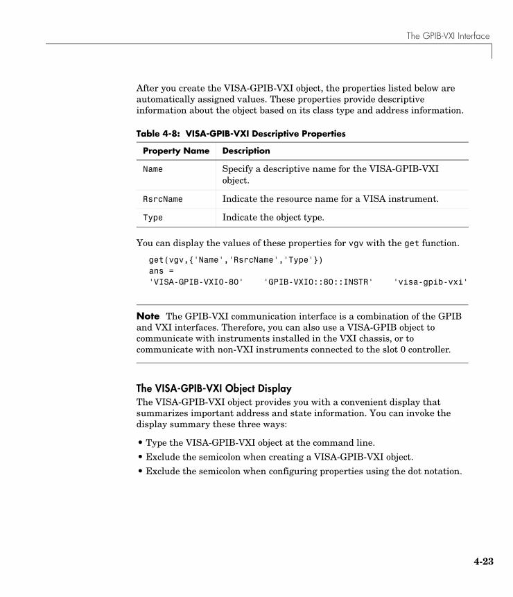
The GPIB-VXI Interface
4-23
After you create the VISA-GPIB-VXI object, the properties listed below are automatically assigned values. These properties provide descriptive information about the object based on its class type and address information.
You can display the values of these properties for vgv with the get function.
get(vgv,{'Name','RsrcName','Type'})ans = 'VISA-GPIB-VXI0-80' 'GPIB-VXI0::80::INSTR' 'visa-gpib-vxi'
Note The GPIB-VXI communication interface is a combination of the GPIB and VXI interfaces. Therefore, you can also use a VISA-GPIB object to communicate with instruments installed in the VXI chassis, or to communicate with non-VXI instruments connected to the slot 0 controller.
The VISA-GPIB-VXI Object DisplayThe VISA-GPIB-VXI object provides you with a convenient display that summarizes important address and state information. You can invoke the display summary these three ways:
• Type the VISA-GPIB-VXI object at the command line.
• Exclude the semicolon when creating a VISA-GPIB-VXI object.
• Exclude the semicolon when configuring properties using the dot notation.
Table 4-8: VISA-GPIB-VXI Descriptive Properties
Property Name Description
Name Specify a descriptive name for the VISA-GPIB-VXI object.
RsrcName Indicate the resource name for a VISA instrument.
Type Indicate the object type.

4 Controlling Instruments Using the VISA Standard
4-24
The display summary for the VISA-GPIB-VXI object vgv is given below.
VISA-GPIB-VXI Object Using AGILENT Adaptor : VISA-GPIB-VXI0-80
Communication Address ChassisIndex: 0LogicalAddress: 80
Communication State Status: closedRecordStatus: off
Read/Write State TransferStatus: idleBytesAvailable: 0ValuesReceived: 0ValuesSent: 0
The VISA-GPIB-VXI AddressThe VISA-GPIB-VXI address consists of a VXI component and a GPIB component. The VXI component includes
• The chassis index of the VXI chassis
• The logical address of the VXI instrument; the logical address must be 0, or it must be divisible by 8
• The slot of the VXI instrument
The GPIB component includes
• The board index of the GPIB controller installed in your computer
• The primary address of the GPIB-VXI command module in slot 0
• The secondary address of the VXI instrument
You must specify the logical address value via the resource name during VISA-GPIB-VXI object creation. Additionally, you must include the chassis
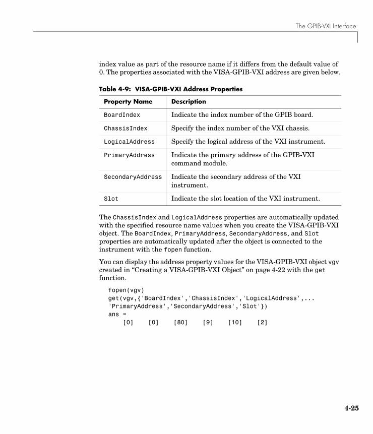
The GPIB-VXI Interface
4-25
index value as part of the resource name if it differs from the default value of 0. The properties associated with the VISA-GPIB-VXI address are given below.
The ChassisIndex and LogicalAddress properties are automatically updated with the specified resource name values when you create the VISA-GPIB-VXI object. The BoardIndex, PrimaryAddress, SecondaryAddress, and Slot properties are automatically updated after the object is connected to the instrument with the fopen function.
You can display the address property values for the VISA-GPIB-VXI object vgv created in “Creating a VISA-GPIB-VXI Object” on page 4-22 with the get function.
fopen(vgv)get(vgv,{'BoardIndex','ChassisIndex','LogicalAddress',...'PrimaryAddress','SecondaryAddress','Slot'})ans = [0] [0] [80] [9] [10] [2]
Table 4-9: VISA-GPIB-VXI Address Properties
Property Name Description
BoardIndex Indicate the index number of the GPIB board.
ChassisIndex Specify the index number of the VXI chassis.
LogicalAddress Specify the logical address of the VXI instrument.
PrimaryAddress Indicate the primary address of the GPIB-VXI command module.
SecondaryAddress Indicate the secondary address of the VXI instrument.
Slot Indicate the slot location of the VXI instrument.
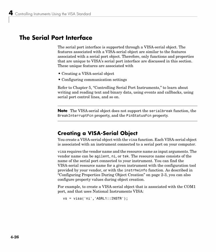
4 Controlling Instruments Using the VISA Standard
4-26
The Serial Port InterfaceThe serial port interface is supported through a VISA-serial object. The features associated with a VISA-serial object are similar to the features associated with a serial port object. Therefore, only functions and properties that are unique to VISA’s serial port interface are discussed in this section. These unique features are associated with
• Creating a VISA-serial object
• Configuring communication settings
Refer to Chapter 5, “Controlling Serial Port Instruments,” to learn about writing and reading text and binary data, using events and callbacks, using serial port control lines, and so on.
Note The VISA-serial object does not support the serialbreak function, the BreakInterruptFcn property, and the PinStatusFcn property.
Creating a VISA-Serial ObjectYou create a VISA-serial object with the visa function. Each VISA-serial object is associated with an instrument connected to a serial port on your computer.
visa requires the vendor name and the resource name as input arguments. The vendor name can be agilent, ni, or tek. The resource name consists of the name of the serial port connected to your instrument. You can find the VISA-serial resource name for a given instrument with the configuration tool provided by your vendor, or with the instrhwinfo function. As described in “Configuring Properties During Object Creation” on page 2-3, you can also configure property values during object creation.
For example, to create a VISA-serial object that is associated with the COM1 port, and that uses National Instruments VISA:
vs = visa('ni','ASRL1::INSTR');
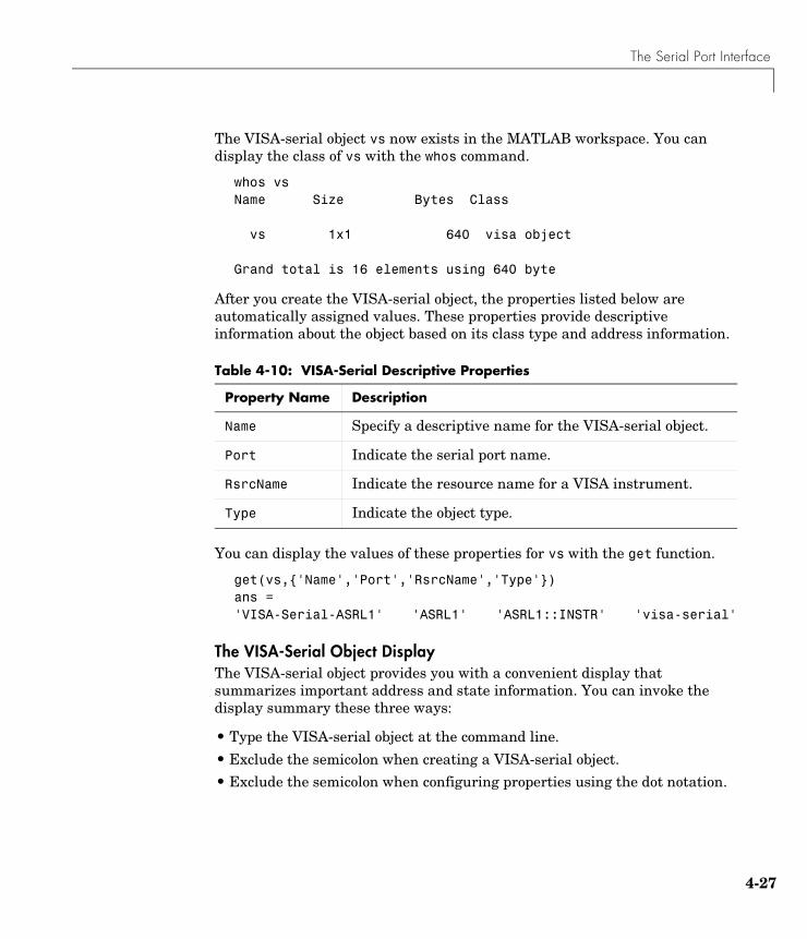
The Serial Port Interface
4-27
The VISA-serial object vs now exists in the MATLAB workspace. You can display the class of vs with the whos command.
whos vsName Size Bytes Class
vs 1x1 640 visa object
Grand total is 16 elements using 640 byte
After you create the VISA-serial object, the properties listed below are automatically assigned values. These properties provide descriptive information about the object based on its class type and address information.
You can display the values of these properties for vs with the get function.
get(vs,{'Name','Port','RsrcName','Type'})ans = 'VISA-Serial-ASRL1' 'ASRL1' 'ASRL1::INSTR' 'visa-serial'
The VISA-Serial Object DisplayThe VISA-serial object provides you with a convenient display that summarizes important address and state information. You can invoke the display summary these three ways:
• Type the VISA-serial object at the command line.
• Exclude the semicolon when creating a VISA-serial object.
• Exclude the semicolon when configuring properties using the dot notation.
Table 4-10: VISA-Serial Descriptive Properties
Property Name Description
Name Specify a descriptive name for the VISA-serial object.
Port Indicate the serial port name.
RsrcName Indicate the resource name for a VISA instrument.
Type Indicate the object type.

4 Controlling Instruments Using the VISA Standard
4-28
The display summary for the VISA-serial object vs is given below.
VISA-Serial Object Using NI Adaptor : VISA-Serial-ASRL1
Communication Settings Port: ASRL1BaudRate: 9600Terminator: 'LF'
Communication State Status: closedRecordStatus: off
Read/Write State TransferStatus: idleBytesAvailable: 0ValuesReceived: 0ValuesSent: 0
Configuring Communication SettingsBefore you can write or read data, both the VISA-serial object and the instrument must have identical communication settings. Configuring serial port communications involves specifying values for properties that control the baud rate and the serial data format. These properties are given below.
Table 4-11: VISA-Serial Communication Properties
Property Name Description
BaudRate Specify the rate at which bits are transmitted.
DataBits Specify the number of data bits to transmit.
Parity Specify the type of parity checking.
StopBits Specify the number of bits used to indicate the end of a byte.
Terminator Specify the character used to terminate commands written to the instrument.
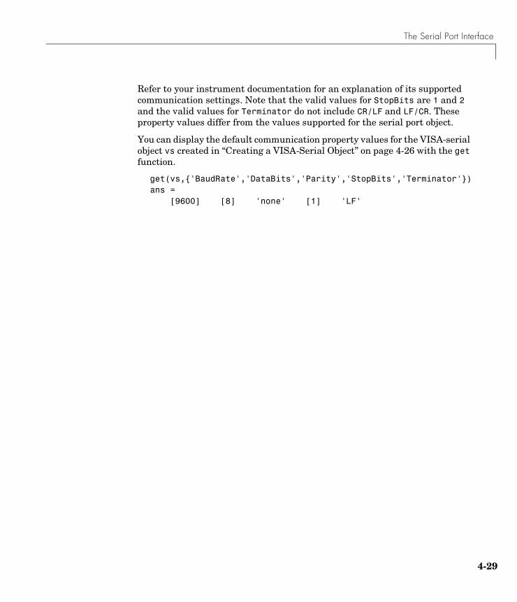
The Serial Port Interface
4-29
Refer to your instrument documentation for an explanation of its supported communication settings. Note that the valid values for StopBits are 1 and 2 and the valid values for Terminator do not include CR/LF and LF/CR. These property values differ from the values supported for the serial port object.
You can display the default communication property values for the VISA-serial object vs created in “Creating a VISA-Serial Object” on page 4-26 with the get function.
get(vs,{'BaudRate','DataBits','Parity','StopBits','Terminator'})ans =
[9600] [8] 'none' [1] 'LF'

4 Controlling Instruments Using the VISA Standard
4-30
5Controlling Serial Port Instruments
This chapter describes specific issues related to controlling instruments that use the serial port. The sections are as follows.
Serial Port Overview (p. 5-2) Basic features of the serial port.
Creating a Serial Port Object (p. 5-16)
The serial port object establishes a connection between MATLAB and the instrument via serial port.
Configuring Communication Settings (p. 5-18)
Communication settings are associated with the baud rate and serial data format.
Writing and Reading Data (p. 5-19)
Port-specific issues related to writing and reading data with a serial port object.
Events and Callbacks (p. 5-24)
Enhance your instrument control application using events and callbacks.
Using Control Pins (p. 5-29) The control pins allow you to signal the presence of connected devices and to control the flow of data.
5 Controlling Serial Port Instruments
5-2
Serial Port OverviewThis section provides an overview of the serial port. Topics include
• What is Serial Communication?
• The Serial Port Interface Standard
• Connecting Two Devices with a Serial Cable
• Serial Port Signals and Pin Assignments
• Serial Data Format
• Finding Serial Port Information for Your Platform
For many serial port applications, you can communicate with your instrument without detailed knowledge of how the serial port works. Communication is established through a serial port object, which you create in the MATLAB workspace.
If your application is straightforward, or if you are already familiar with the topics mentioned above, you might want to begin with “Creating a Serial Port Object” on page 5-16. If you want a high-level description of all the steps you are likely to take when communicating with your instrument, refer to Chapter 2, “The Instrument Control Session.”
What Is Serial Communication?Serial communication is the most common low-level protocol for communicating between two or more devices. Normally, one device is a computer, while the other device can be a modem, a printer, another computer, or a scientific instrument such as an oscilloscope or a function generator.
As the name suggests, the serial port sends and receives bytes of information in a serial fashion — one bit at a time. These bytes are transmitted using either a binary format or a text (ASCII) format.
The Serial Port Interface StandardOver the years, several serial port interface standards for connecting computers to peripheral devices have been developed. These standards include RS-232, RS-422, and RS-485 — all of which are supported by the serial port object. Of these, the most widely used standard is RS-232, which stands for Recommended Standard number 232.
Serial Port Overview
5-3
The current version of this standard is designated as TIA/EIA-232C, which is published by the Telecommunications Industry Association. However, the term “RS-232” is still in popular use, and is used in this guide when referring to a serial communication port that follows the TIA/EIA-232 standard. RS-232 defines these serial port characteristics:
• The maximum bit transfer rate and cable length
• The names, electrical characteristics, and functions of signals
• The mechanical connections and pin assignments
Primary communication is accomplished using three pins: the Transmit Data pin, the Receive Data pin, and the Ground pin. Other pins are available for data flow control, but are not required.
Note In this guide, it is assumed you are using the RS-232 standard. Refer to your device documentation to see which interface standard you can use.
Connecting Two Devices with a Serial CableThe RS-232 standard defines the two devices connected with a serial cable as the Data Terminal Equipment (DTE) and Data Circuit-Terminating Equipment (DCE). This terminology reflects the RS-232 origin as a standard for communication between a computer terminal and a modem.
Throughout this guide, your computer is considered a DTE, while peripheral devices such as modems and printers are considered DCEs. Note that many scientific instruments function as DTEs.
Because RS-232 mainly involves connecting a DTE to a DCE, the pin assignments are defined such that straight-through cabling is used, where pin 1 is connected to pin 1, pin 2 is connected to pin 2, and so on. A DTE to DCE serial connection using the transmit data (TD) pin and the receive data (RD)
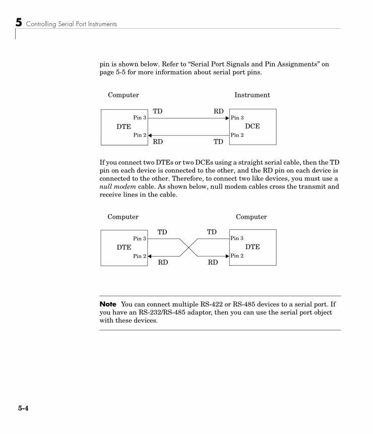
5 Controlling Serial Port Instruments
5-4
pin is shown below. Refer to “Serial Port Signals and Pin Assignments” on page 5-5 for more information about serial port pins.
If you connect two DTEs or two DCEs using a straight serial cable, then the TD pin on each device is connected to the other, and the RD pin on each device is connected to the other. Therefore, to connect two like devices, you must use a null modem cable. As shown below, null modem cables cross the transmit and receive lines in the cable.
Note You can connect multiple RS-422 or RS-485 devices to a serial port. If you have an RS-232/RS-485 adaptor, then you can use the serial port object with these devices.
DTE DCEPin 2
Pin 3
Pin 2
Pin 3
RD TD
TD RD
Computer Instrument
DTE DTE
TD
Pin 2
Pin 3
Pin 2
Pin 3TD
RDRD
Computer Computer
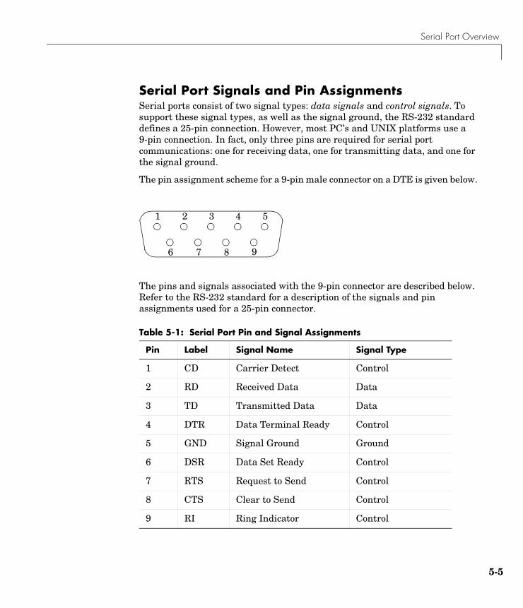
Serial Port Overview
5-5
Serial Port Signals and Pin AssignmentsSerial ports consist of two signal types: data signals and control signals. To support these signal types, as well as the signal ground, the RS-232 standard defines a 25-pin connection. However, most PC’s and UNIX platforms use a 9-pin connection. In fact, only three pins are required for serial port communications: one for receiving data, one for transmitting data, and one for the signal ground.
The pin assignment scheme for a 9-pin male connector on a DTE is given below.
The pins and signals associated with the 9-pin connector are described below. Refer to the RS-232 standard for a description of the signals and pin assignments used for a 25-pin connector.
Table 5-1: Serial Port Pin and Signal Assignments
Pin Label Signal Name Signal Type
1 CD Carrier Detect Control
2 RD Received Data Data
3 TD Transmitted Data Data
4 DTR Data Terminal Ready Control
5 GND Signal Ground Ground
6 DSR Data Set Ready Control
7 RTS Request to Send Control
8 CTS Clear to Send Control
9 RI Ring Indicator Control
1 2 3 4 5
6 7 8 9
5 Controlling Serial Port Instruments
5-6
The term “data set” is synonymous with “modem” or “device,” while the term “data terminal” is synonymous with “computer.”
Note The serial port pin and signal assignments are with respect to the DTE. For example, data is transmitted from the TD pin of the DTE to the RD pin of the DCE.
Signal StatesSignals can be in either an active state or an inactive state. An active state corresponds to the binary value 1, while an inactive state corresponds to the binary value 0. An active signal state is often described as logic 1, on, true, or a mark. An inactive signal state is often described as logic 0, off, false, or a space.
For data signals, the “on” state occurs when the received signal voltage is more negative than -3 volts, while the “off” state occurs for voltages more positive than 3 volts. For control signals, the “on” state occurs when the received signal voltage is more positive than 3 volts, while the “off” state occurs for voltages more negative than -3 volts. The voltage between -3 volts and +3 volts is considered a transition region, and the signal state is undefined.
To bring the signal to the “on” state, the controlling device unasserts (or lowers) the value for data pins and asserts (or raises) the value for control pins. Conversely, to bring the signal to the “off” state, the controlling device asserts the value for data pins and unasserts the value for control pins.
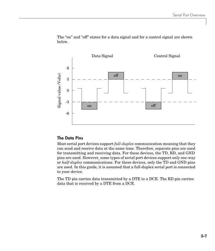
Serial Port Overview
5-7
The “on” and “off” states for a data signal and for a control signal are shown below.
The Data PinsMost serial port devices support full-duplex communication meaning that they can send and receive data at the same time. Therefore, separate pins are used for transmitting and receiving data. For these devices, the TD, RD, and GND pins are used. However, some types of serial port devices support only one-way or half-duplex communications. For these devices, only the TD and GND pins are used. In this guide, it is assumed that a full-duplex serial port is connected to your device.
The TD pin carries data transmitted by a DTE to a DCE. The RD pin carries data that is received by a DTE from a DCE.
-6
Sig
nal
val
ue (V
olts
)
-3
0
3
6
Data Signal Control Signal
on
off
off
on
5 Controlling Serial Port Instruments
5-8
The Control Pins9-pin serial ports provide several control pins that
• Signal the presence of connected devices
• Control the flow of data
The control pins include RTS and CTS, DTR and DSR, CD, and RI.
The RTS and CTS Pins. The RTS and CTS pins are used to signal whether the devices are ready to send or receive data. This type of data flow control — called hardware handshaking — is used to prevent data loss during transmission. When enabled for both the DTE and DCE, hardware handshaking using RTS and CTS follows these steps:
1 The DTE asserts the RTS pin to instruct the DCE that it is ready to receive data.
2 The DCE asserts the CTS pin indicating that it is clear to send data over the TD pin. If data can no longer be sent, the CTS pin is unasserted.
3 The data is transmitted to the DTE over the TD pin. If data can no longer be accepted, the RTS pin is unasserted by the DTE and the data transmission is stopped.
To enable hardware handshaking, refer to “Controlling the Flow of Data: Handshaking” on page 5-32.
The DTR and DSR Pins. Many devices use the DSR and DTR pins to signal if they are connected and powered. Signaling the presence of connected devices using DTR and DSR follows these steps:
1 The DTE asserts the DTR pin to request that the DCE connect to the communication line.
2 The DCE asserts the DSR pin to indicate that it is connected.
3 DCE unasserts the DSR pin when it is disconnected from the communication line.
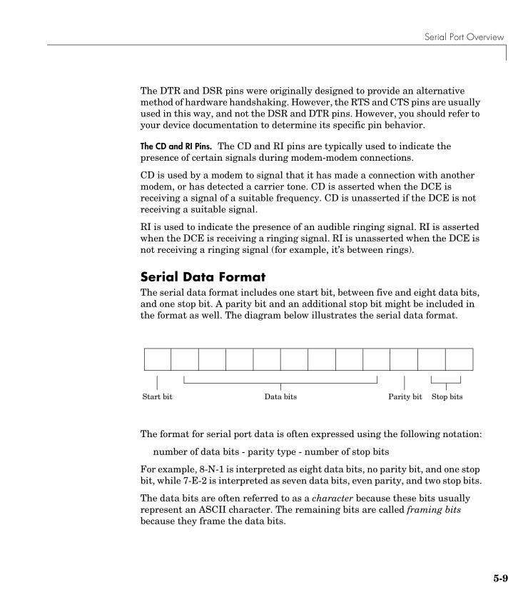
Serial Port Overview
5-9
The DTR and DSR pins were originally designed to provide an alternative method of hardware handshaking. However, the RTS and CTS pins are usually used in this way, and not the DSR and DTR pins. However, you should refer to your device documentation to determine its specific pin behavior.
The CD and RI Pins. The CD and RI pins are typically used to indicate the presence of certain signals during modem-modem connections.
CD is used by a modem to signal that it has made a connection with another modem, or has detected a carrier tone. CD is asserted when the DCE is receiving a signal of a suitable frequency. CD is unasserted if the DCE is not receiving a suitable signal.
RI is used to indicate the presence of an audible ringing signal. RI is asserted when the DCE is receiving a ringing signal. RI is unasserted when the DCE is not receiving a ringing signal (for example, it’s between rings).
Serial Data FormatThe serial data format includes one start bit, between five and eight data bits, and one stop bit. A parity bit and an additional stop bit might be included in the format as well. The diagram below illustrates the serial data format.
The format for serial port data is often expressed using the following notation:
number of data bits - parity type - number of stop bits
For example, 8-N-1 is interpreted as eight data bits, no parity bit, and one stop bit, while 7-E-2 is interpreted as seven data bits, even parity, and two stop bits.
The data bits are often referred to as a character because these bits usually represent an ASCII character. The remaining bits are called framing bits because they frame the data bits.
Start bit Data bits Parity bit Stop bits
5 Controlling Serial Port Instruments
5-10
Bytes Versus ValuesThe collection of bits that comprise the serial data format is called a byte. At first, this term might seem inaccurate because a byte is 8 bits and the serial data format can range between 7 bits and 12 bits. However, when serial data is stored on your computer, the framing bits are stripped away, and only the data bits are retained. Moreover, eight data bits are always used regardless of the number of data bits specified for transmission, with the unused bits assigned a value of 0.
When reading or writing data, you might need to specify a value, which can consist of one or more bytes. For example, if you read one value from a device using the int32 format, then that value consists of four bytes. For more information about reading and writing values, refer to “Writing and Reading Data” on page 5-19.
Synchronous and Asynchronous CommunicationThe RS-232 standard supports two types of communication protocols: synchronous and asynchronous.
Using the synchronous protocol, all transmitted bits are synchronized to a common clock signal. The two devices initially synchronize themselves to each other, and then continually send characters to stay synchronized. Even when actual data is not really being sent, a constant flow of bits allows each device to know where the other is at any given time. That is, each bit that is sent is either actual data or an idle character. Synchronous communications allows faster data transfer rates than asynchronous methods, because additional bits to mark the beginning and end of each data byte are not required.
Using the asynchronous protocol, each device uses its own internal clock resulting in bytes that are transferred at arbitrary times. So, instead of using time as a way to synchronize the bits, the data format is used.
In particular, the data transmission is synchronized using the start bit of the word, while one or more stop bits indicate the end of the word. The requirement to send these additional bits causes asynchronous communications to be slightly slower than synchronous. However, it has the advantage that the processor does not have to deal with the additional idle characters. Most serial ports operate asynchronously.
Serial Port Overview
5-11
Note When used in this guide, the terms “synchronous” and “asynchronous” refer to whether read or write operations block access to the MATLAB command line.
How Are the Bits Transmitted?By definition, serial data is transmitted one bit at a time. The order in which the bits are transmitted follows these steps:
1 The start bit is transmitted with a value of 0.
2 The data bits are transmitted. The first data bit corresponds to the least significant bit (LSB), while the last data bit corresponds to the most significant bit (MSB).
3 The parity bit (if defined) is transmitted.
4 One or two stop bits are transmitted, each with a value of 1.
The number of bits transferred per second is given by the baud rate. The transferred bits include the start bit, the data bits, the parity bit (if defined), and the stop bits.
Start and Stop BitsAs described in “Synchronous and Asynchronous Communication” on page 5-10, most serial ports operate asynchronously. This means that the transmitted byte must be identified by start and stop bits. The start bit indicates when the data byte is about to begin and the stop bit(s) indicates when the data byte has been transferred. The process of identifying bytes with the serial data format follows these steps:
1 When a serial port pin is idle (not transmitting data), then it is in an “on” state.
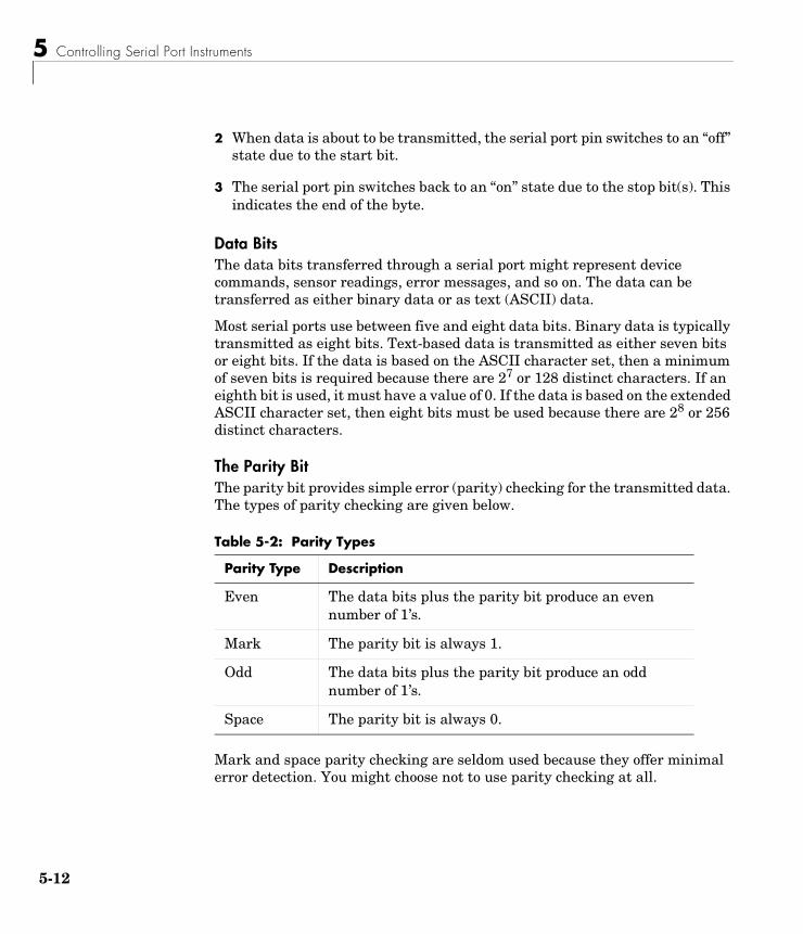
5 Controlling Serial Port Instruments
5-12
2 When data is about to be transmitted, the serial port pin switches to an “off” state due to the start bit.
3 The serial port pin switches back to an “on” state due to the stop bit(s). This indicates the end of the byte.
Data BitsThe data bits transferred through a serial port might represent device commands, sensor readings, error messages, and so on. The data can be transferred as either binary data or as text (ASCII) data.
Most serial ports use between five and eight data bits. Binary data is typically transmitted as eight bits. Text-based data is transmitted as either seven bits or eight bits. If the data is based on the ASCII character set, then a minimum of seven bits is required because there are 27 or 128 distinct characters. If an eighth bit is used, it must have a value of 0. If the data is based on the extended ASCII character set, then eight bits must be used because there are 28 or 256 distinct characters.
The Parity BitThe parity bit provides simple error (parity) checking for the transmitted data. The types of parity checking are given below.
Mark and space parity checking are seldom used because they offer minimal error detection. You might choose not to use parity checking at all.
Table 5-2: Parity Types
Parity Type Description
Even The data bits plus the parity bit produce an even number of 1’s.
Mark The parity bit is always 1.
Odd The data bits plus the parity bit produce an odd number of 1’s.
Space The parity bit is always 0.

Serial Port Overview
5-13
The parity checking process follows these steps:
1 The transmitting device sets the parity bit to 0 or to 1 depending on the data bit values and the type of parity checking selected.
2 The receiving device checks if the parity bit is consistent with the transmitted data. If it is, then the data bits are accepted. If it is not, then an error is returned.
Note Parity checking can detect only 1 bit errors. Multiple-bit errors can appear as valid data.
For example, suppose the data bits 01110001 are transmitted to your computer. If even parity is selected, then the parity bit is set to 0 by the transmitting device to produce an even number of 1s. If odd parity is selected, then the parity bit is set to 1 by the transmitting device to produce an odd number of 1s.
Finding Serial Port Information for Your PlatformThis section describes how to find serial port information using the resources provided by Windows and UNIX platforms.
Note Your operating system provides default values for all serial port settings. However, these settings are overridden by your MATLAB code, and will have no effect on your serial port application.
You can also use the instrhwinfo function to return the available serial ports programmatically.

5 Controlling Serial Port Instruments
5-14
Windows PlatformYou can easily access serial port information through the Windows Control Panel. You can invoke the Control Panel with the Start button (Start -> Settings -> Control Panel).
For Windows NT, you access the serial ports by selecting the Ports icon within the Control Panel. The resulting Ports dialog box is shown below.
To obtain information on the possible settings for COM1, select this port under the Ports list box and then select Settings.
You can access serial port information for the Windows 98 and Windows 2000 operating systems with the System Properties dialog box, which is available through the Control Panel.
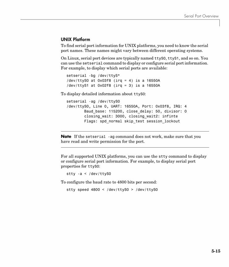
Serial Port Overview
5-15
UNIX PlatformTo find serial port information for UNIX platforms, you need to know the serial port names. These names might vary between different operating systems.
On Linux, serial port devices are typically named ttyS0, ttyS1, and so on. You can use the setserial command to display or configure serial port information. For example, to display which serial ports are available:
setserial -bg /dev/ttyS*/dev/ttyS0 at 0x03f8 (irq = 4) is a 16550A/dev/ttyS1 at 0x02f8 (irq = 3) is a 16550A
To display detailed information about ttyS0:
setserial -ag /dev/ttyS0/dev/ttyS0, Line 0, UART: 16550A, Port: 0x03f8, IRQ: 4 Baud_base: 115200, close_delay: 50, divisor: 0 closing_wait: 3000, closing_wait2: infinte Flags: spd_normal skip_test session_lockout
Note If the setserial -ag command does not work, make sure that you have read and write permission for the port.
For all supported UNIX platforms, you can use the stty command to display or configure serial port information. For example, to display serial port properties for ttyS0:
stty -a < /dev/ttyS0
To configure the baud rate to 4800 bits per second:
stty speed 4800 < /dev/ttyS0 > /dev/ttyS0
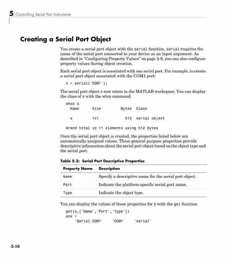
5 Controlling Serial Port Instruments
5-16
Creating a Serial Port ObjectYou create a serial port object with the serial function. serial requires the name of the serial port connected to your device as an input argument. As described in “Configuring Property Values” on page 2-9, you can also configure property values during object creation.
Each serial port object is associated with one serial port. For example, to create a serial port object associated with the COM1 port:
s = serial('COM1');
The serial port object s now exists in the MATLAB workspace. You can display the class of s with the whos command.
whos s Name Size Bytes Class
s 1x1 512 serial object
Grand total is 11 elements using 512 bytes
Once the serial port object is created, the properties listed below are automatically assigned values. These general purpose properties provide descriptive information about the serial port object based on the object type and the serial port.
You can display the values of these properties for s with the get function.
get(s,{'Name','Port','Type'})ans = 'Serial-COM1' 'COM1' 'serial'
Table 5-3: Serial Port Descriptive Properties
Property Name Description
Name Specify a descriptive name for the serial port object.
Port Indicate the platform-specific serial port name.
Type Indicate the object type.
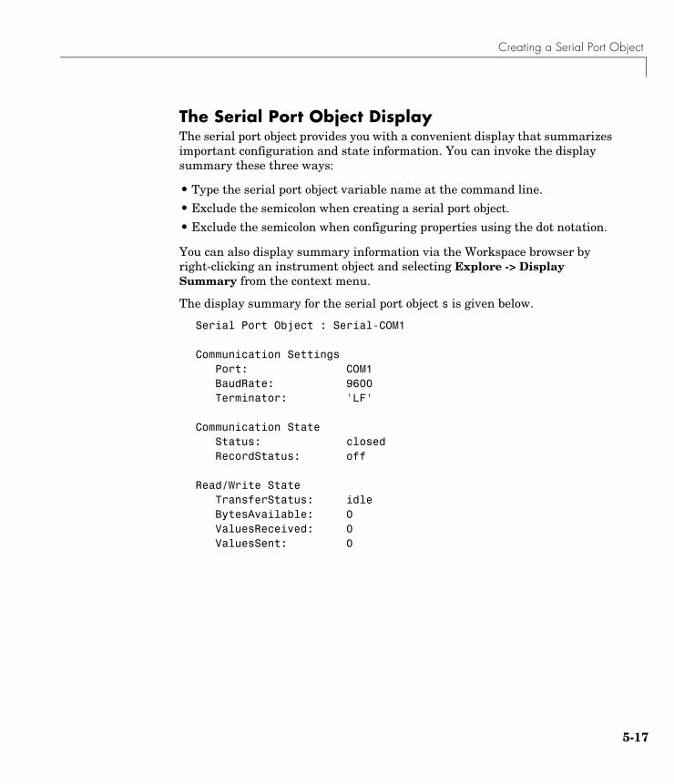
Creating a Serial Port Object
5-17
The Serial Port Object DisplayThe serial port object provides you with a convenient display that summarizes important configuration and state information. You can invoke the display summary these three ways:
• Type the serial port object variable name at the command line.
• Exclude the semicolon when creating a serial port object.
• Exclude the semicolon when configuring properties using the dot notation.
You can also display summary information via the Workspace browser by right-clicking an instrument object and selecting Explore -> Display Summary from the context menu.
The display summary for the serial port object s is given below.
Serial Port Object : Serial-COM1
Communication Settings Port: COM1BaudRate: 9600Terminator: 'LF'
Communication State Status: closedRecordStatus: off
Read/Write State TransferStatus: idleBytesAvailable: 0ValuesReceived: 0ValuesSent: 0
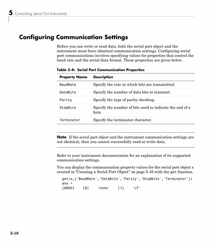
5 Controlling Serial Port Instruments
5-18
Configuring Communication SettingsBefore you can write or read data, both the serial port object and the instrument must have identical communication settings. Configuring serial port communications involves specifying values for properties that control the baud rate and the serial data format. These properties are given below.
Note If the serial port object and the instrument communication settings are not identical, then you cannot successfully read or write data.
Refer to your instrument documentation for an explanation of its supported communication settings.
You can display the communication property values for the serial port object s created in “Creating a Serial Port Object” on page 5-16 with the get function.
get(s,{'BaudRate','DataBits','Parity','StopBits','Terminator'})ans = [9600] [8] 'none' [1] 'LF'
Table 5-4: Serial Port Communication Properties
Property Name Description
BaudRate Specify the rate at which bits are transmitted.
DataBits Specify the number of data bits to transmit.
Parity Specify the type of parity checking.
StopBits Specify the number of bits used to indicate the end of a byte.
Terminator Specify the terminator character.
Writing and Reading Data
5-19
Writing and Reading DataThis section describes interface-specific issues related to writing and reading data with a serial port object. Topics include
• Asynchronous write and read operations
• Rules for completing write and read operations
• An example that illustrates writing and reading text data
For a general overview about writing and reading data, as well as a list of all associated functions and properties, refer to “Writing and Reading Data” on page 2-12.
Asynchronous Write and Read OperationsAsynchronous write and read operations do not block access to the MATLAB command line. Additionally, while an asynchronous operation is in progress you can
• Execute a read (write) operation while an asynchronous write (read) operation is in progress. This is because serial ports have separate pins for reading and writing.
• Make use of all supported callback properties. Refer to “Events and Callbacks” on page 5-24 for more information about the callback properties supported by serial port objects.
The process of writing data asynchronously is given in “Synchronous Versus Asynchronous Write Operations” on page 2-17. The process of reading data asynchronously is described in the next section.
Asynchronous Read OperationsFor serial port objects, you specify whether read operations are synchronous or asynchronous with the ReadAsyncMode property. You can configure ReadAsyncMode to continuous or manual.
If ReadAsyncMode is continuous (the default value), the serial port object continuously queries the instrument to determine if data is available to be read. If data is available, it is asynchronously stored in the input buffer. To transfer the data from the input buffer to MATLAB, you use one of the
5 Controlling Serial Port Instruments
5-20
synchronous (blocking) read functions such as fgetl, fgets, fscanf, or fread. If data is available in the input buffer, these functions will return quickly.
s = serial('COM1');fopen(s)s.ReadAsyncMode = 'continuous';fprintf(s,'*IDN?')s.BytesAvailableans = 56out = fscanf(s);
If ReadAsyncMode is manual, the serial port object does not continuously query the instrument to determine if data is available to be read. To read data asynchronously, you use the readasync function. You then use one of the synchronous read functions to transfer data from the input buffer to MATLAB.
s.ReadAsyncMode = 'manual';fprintf(s,'*IDN?')s.BytesAvailableans = 0readasync(s)s.BytesAvailableans = 56out = fscanf(s);
Rules for Completing Write and Read OperationsThe rules for completing synchronous and asynchronous read and write operations are described below.
Completing Write OperationsA write operation using fprintf or fwrite completes when one of these conditions is satisfied:
• The specified data is written.
• The time specified by the Timeout property passes.
Writing and Reading Data
5-21
In addition to these rules, you can stop an asynchronous write operation at any time with the stopasync function.
A text command is processed by the instrument only when it receives the required terminator. For serial port objects, each occurrence of \n in the ASCII command is replaced with the Terminator property value. Because the default format for fprintf is %s\n, all commands written to the instrument will end with the Terminator value. The default value of Terminator is the line feed character. The terminator required by your instrument will be described in its documentation.
Completing Read OperationsA read operation with fgetl, fgets, fscanf, or readasync completes when one of these conditions is satisfied:
• The terminator specified by the Terminator property is read.
• The time specified by the Timeout property passes.
• The input buffer is filled.
• The specified number of values is read (fscanf and readasync only).
A read operation with fread completes when one of these conditions is satisfied:
• The time specified by the Timeout property passes.
• The specified number of values is read.
In addition to these rules, you can stop an asynchronous read operation at any time with the stopasync function.
Example: Writing and Reading Text DataThis example illustrates how to communicate with a serial port instrument by writing and reading text data.
The instrument is a Tektronix TDS 210 two-channel oscilloscope connected to the serial port COM1. Therefore, many of the commands given below are specific to this instrument. A sine wave is input into channel 2 of the oscilloscope, and your job is to measure the peak-to-peak voltage of the input signal.
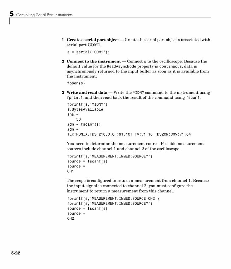
5 Controlling Serial Port Instruments
5-22
1 Create a serial port object — Create the serial port object s associated with serial port COM1.
s = serial('COM1');
2 Connect to the instrument — Connect s to the oscilloscope. Because the default value for the ReadAsyncMode property is continuous, data is asynchronously returned to the input buffer as soon as it is available from the instrument.
fopen(s)
3 Write and read data — Write the *IDN? command to the instrument using fprintf, and then read back the result of the command using fscanf.
fprintf(s,'*IDN?')s.BytesAvailableans = 56idn = fscanf(s)idn =TEKTRONIX,TDS 210,0,CF:91.1CT FV:v1.16 TDS2CM:CMV:v1.04
You need to determine the measurement source. Possible measurement sources include channel 1 and channel 2 of the oscilloscope.
fprintf(s,'MEASUREMENT:IMMED:SOURCE?')source = fscanf(s)source =CH1
The scope is configured to return a measurement from channel 1. Because the input signal is connected to channel 2, you must configure the instrument to return a measurement from this channel.
fprintf(s,'MEASUREMENT:IMMED:SOURCE CH2')fprintf(s,'MEASUREMENT:IMMED:SOURCE?')source = fscanf(s)source =CH2
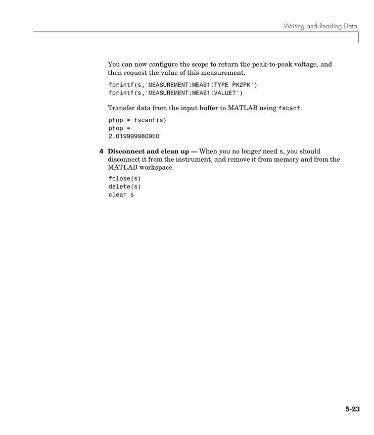
Writing and Reading Data
5-23
You can now configure the scope to return the peak-to-peak voltage, and then request the value of this measurement.
fprintf(s,'MEASUREMENT:MEAS1:TYPE PK2PK')fprintf(s,'MEASUREMENT:MEAS1:VALUE?')
Transfer data from the input buffer to MATLAB using fscanf.
ptop = fscanf(s)ptop =2.0199999809E0
4 Disconnect and clean up — When you no longer need s, you should disconnect it from the instrument, and remove it from memory and from the MATLAB workspace.
fclose(s)delete(s)clear s
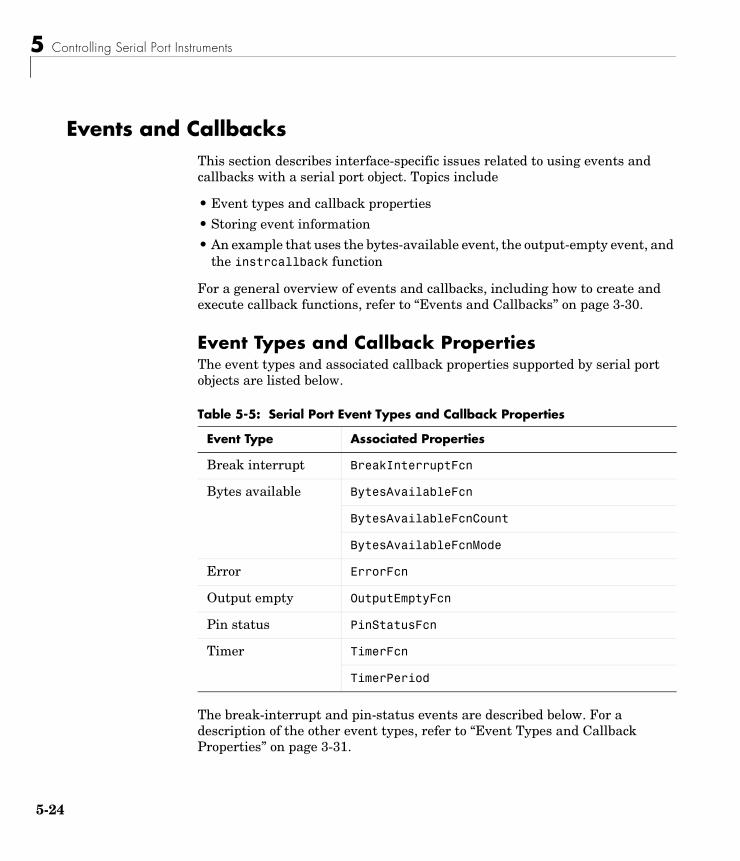
5 Controlling Serial Port Instruments
5-24
Events and CallbacksThis section describes interface-specific issues related to using events and callbacks with a serial port object. Topics include
• Event types and callback properties
• Storing event information
• An example that uses the bytes-available event, the output-empty event, and the instrcallback function
For a general overview of events and callbacks, including how to create and execute callback functions, refer to “Events and Callbacks” on page 3-30.
Event Types and Callback PropertiesThe event types and associated callback properties supported by serial port objects are listed below.
The break-interrupt and pin-status events are described below. For a description of the other event types, refer to “Event Types and Callback Properties” on page 3-31.
Table 5-5: Serial Port Event Types and Callback Properties
Event Type Associated Properties
Break interrupt BreakInterruptFcn
Bytes available BytesAvailableFcn
BytesAvailableFcnCount
BytesAvailableFcnMode
Error ErrorFcn
Output empty OutputEmptyFcn
Pin status PinStatusFcn
Timer TimerFcn
TimerPeriod
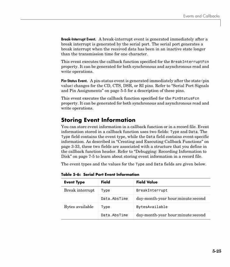
Events and Callbacks
5-25
Break-Interrupt Event. A break-interrupt event is generated immediately after a break interrupt is generated by the serial port. The serial port generates a break interrupt when the received data has been in an inactive state longer than the transmission time for one character.
This event executes the callback function specified for the BreakInterruptFcn property. It can be generated for both synchronous and asynchronous read and write operations.
Pin-Status Event. A pin-status event is generated immediately after the state (pin value) changes for the CD, CTS, DSR, or RI pins. Refer to “Serial Port Signals and Pin Assignments” on page 5-5 for a description of these pins.
This event executes the callback function specified for the PinStatusFcn property. It can be generated for both synchronous and asynchronous read and write operations.
Storing Event InformationYou can store event information in a callback function or in a record file. Event information stored in a callback function uses two fields: Type and Data. The Type field contains the event type, while the Data field contains event-specific information. As described in “Creating and Executing Callback Functions” on page 3-33, these two fields are associated with a structure that you define in the callback function header. Refer to “Debugging: Recording Information to Disk” on page 7-5 to learn about storing event information in a record file.
The event types and the values for the Type and Data fields are given below.
Table 5-6: Serial Port Event Information
Event Type Field Field Value
Break interrupt Type BreakInterrupt
Data.AbsTime day-month-year hour:minute:second
Bytes available Type BytesAvailable
Data.AbsTime day-month-year hour:minute:second
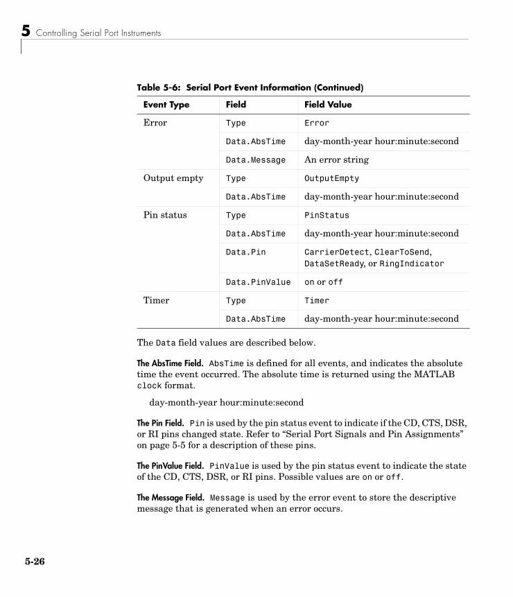
5 Controlling Serial Port Instruments
5-26
The Data field values are described below.
The AbsTime Field. AbsTime is defined for all events, and indicates the absolute time the event occurred. The absolute time is returned using the MATLAB clock format.
day-month-year hour:minute:second
The Pin Field. Pin is used by the pin status event to indicate if the CD, CTS, DSR, or RI pins changed state. Refer to “Serial Port Signals and Pin Assignments” on page 5-5 for a description of these pins.
The PinValue Field. PinValue is used by the pin status event to indicate the state of the CD, CTS, DSR, or RI pins. Possible values are on or off.
The Message Field. Message is used by the error event to store the descriptive message that is generated when an error occurs.
Error Type Error
Data.AbsTime day-month-year hour:minute:second
Data.Message An error string
Output empty Type OutputEmpty
Data.AbsTime day-month-year hour:minute:second
Pin status Type PinStatus
Data.AbsTime day-month-year hour:minute:second
Data.Pin CarrierDetect, ClearToSend, DataSetReady, or RingIndicator
Data.PinValue on or off
Timer Type Timer
Data.AbsTime day-month-year hour:minute:second
Table 5-6: Serial Port Event Information (Continued)
Event Type Field Field Value

Events and Callbacks
5-27
Example: Using Events and CallbacksThis example uses the M-file callback function instrcallback to display event-related information to the command line when a bytes-available event or an output-empty event occurs.
1 Create an instrument object — Create the serial port object s associated with serial port COM1.
s = serial('COM1');
2 Connect to the instrument — Connect s to the Tektronix TDS 210 oscilloscope. Because the default value for the ReadAsyncMode property is continuous, data is asynchronously returned to the input buffer as soon as it is available from the instrument.
fopen(s)
3 Configure properties — Configure s to execute the callback function instrcallback when a bytes-available event or an output-empty event occurs.
s.BytesAvailableFcnMode = 'terminator';s.BytesAvailableFcn = @instrcallback;s.OutputEmptyFcn = @instrcallback;
4 Write and read data — Write the RS232? command asynchronously to the oscilloscope. This command queries the RS-232 settings and returns the baud rate, the software flow control setting, the hardware flow control setting, the parity type, and the terminator.
fprintf(s,'RS232?','async')
instrcallback is called after the RS232? command is sent, and when the terminator is read. The resulting displays are shown below.
OutputEmpty event occurred at 17:37:21 for the object: Serial-COM1.
BytesAvailable event occurred at 17:37:21 for the object: Serial-COM1.
5 Controlling Serial Port Instruments
5-28
Read the data from the input buffer.
out = fscanf(s)out =9600;0;0;NONE;LF
5 Disconnect and clean up — When you no longer need s, you should disconnect it from the instrument, and remove it from memory and from the MATLAB workspace.
fclose(s)delete(s)clear s
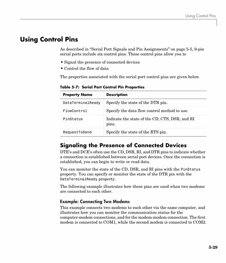
Using Control Pins
5-29
Using Control PinsAs described in “Serial Port Signals and Pin Assignments” on page 5-5, 9-pin serial ports include six control pins. These control pins allow you to
• Signal the presence of connected devices
• Control the flow of data
The properties associated with the serial port control pins are given below.
Signaling the Presence of Connected DevicesDTE’s and DCE’s often use the CD, DSR, RI, and DTR pins to indicate whether a connection is established between serial port devices. Once the connection is established, you can begin to write or read data.
You can monitor the state of the CD, DSR, and RI pins with the PinStatus property. You can specify or monitor the state of the DTR pin with the DataTerminalReady property.
The following example illustrates how these pins are used when two modems are connected to each other.
Example: Connecting Two ModemsThis example connects two modems to each other via the same computer, and illustrates how you can monitor the communication status for the computer-modem connections, and for the modem-modem connection. The first modem is connected to COM1, while the second modem is connected to COM2.
Table 5-7: Serial Port Control Pin Properties
Property Name Description
DataTerminalReady Specify the state of the DTR pin.
FlowControl Specify the data flow control method to use.
PinStatus Indicate the state of the CD, CTS, DSR, and RI pins.
RequestToSend Specify the state of the RTS pin.
5 Controlling Serial Port Instruments
5-30
1 Create the instrument objects — After the modems are powered on, the serial port object s1 is created for the first modem, and the serial port object s2 is created for the second modem.
s1 = serial('COM1');s2 = serial('COM2');
2 Connect to the instruments — s1 and s2 are connected to the modems. Because the default value for the ReadAsyncMode property is continuous, data is asynchronously returned to the input buffers as soon as it is available from the modems.
fopen(s1)fopen(s2)
Because the default value of the DataTerminalReady property is on, the computer (data terminal) is now ready to exchange data with the modems. You can verify that the modems (data sets) are ready to communicate with the computer by examining the value of the Data Set Ready pin using the PinStatus property.
s1.Pinstatusans = CarrierDetect: 'off' ClearToSend: 'on' DataSetReady: 'on' RingIndicator: 'off'
The value of the DataSetReady field is on because both modems were powered on before they were connected to the objects.
3 Configure properties — Both modems are configured for a baud rate of 2400 bits per second and a carriage return (CR) terminator.
s1.BaudRate = 2400;s1.Terminator = 'CR';s2.BaudRate = 2400;s2.Terminator = 'CR';
4 Write and read data — Write the atd command to the first modem. This command puts the modem “off the hook,” which is equivalent to manually lifting a phone receiver.
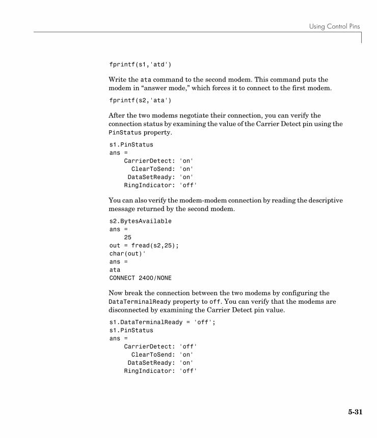
Using Control Pins
5-31
fprintf(s1,'atd')
Write the ata command to the second modem. This command puts the modem in “answer mode,” which forces it to connect to the first modem.
fprintf(s2,'ata')
After the two modems negotiate their connection, you can verify the connection status by examining the value of the Carrier Detect pin using the PinStatus property.
s1.PinStatusans = CarrierDetect: 'on' ClearToSend: 'on' DataSetReady: 'on' RingIndicator: 'off'
You can also verify the modem-modem connection by reading the descriptive message returned by the second modem.
s2.BytesAvailableans = 25out = fread(s2,25);char(out)'ans =ataCONNECT 2400/NONE
Now break the connection between the two modems by configuring the DataTerminalReady property to off. You can verify that the modems are disconnected by examining the Carrier Detect pin value.
s1.DataTerminalReady = 'off';s1.PinStatusans = CarrierDetect: 'off' ClearToSend: 'on' DataSetReady: 'on' RingIndicator: 'off'
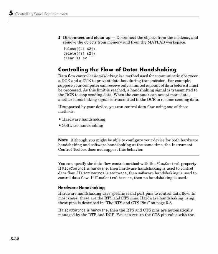
5 Controlling Serial Port Instruments
5-32
5 Disconnect and clean up — Disconnect the objects from the modems, and remove the objects from memory and from the MATLAB workspace.
fclose([s1 s2])delete([s1 s2])clear s1 s2
Controlling the Flow of Data: HandshakingData flow control or handshaking is a method used for communicating between a DCE and a DTE to prevent data loss during transmission. For example, suppose your computer can receive only a limited amount of data before it must be processed. As this limit is reached, a handshaking signal is transmitted to the DCE to stop sending data. When the computer can accept more data, another handshaking signal is transmitted to the DCE to resume sending data.
If supported by your device, you can control data flow using one of these methods:
• Hardware handshaking
• Software handshaking
Note Although you might be able to configure your device for both hardware handshaking and software handshaking at the same time, the Instrument Control Toolbox does not support this behavior.
You can specify the data flow control method with the FlowControl property. If FlowControl is hardware, then hardware handshaking is used to control data flow. If FlowControl is software, then software handshaking is used to control data flow. If FlowControl is none, then no handshaking is used.
Hardware HandshakingHardware handshaking uses specific serial port pins to control data flow. In most cases, these are the RTS and CTS pins. Hardware handshaking using these pins is described in “The RTS and CTS Pins” on page 5-8.
If FlowControl is hardware, then the RTS and CTS pins are automatically managed by the DTE and DCE. You can return the CTS pin value with the
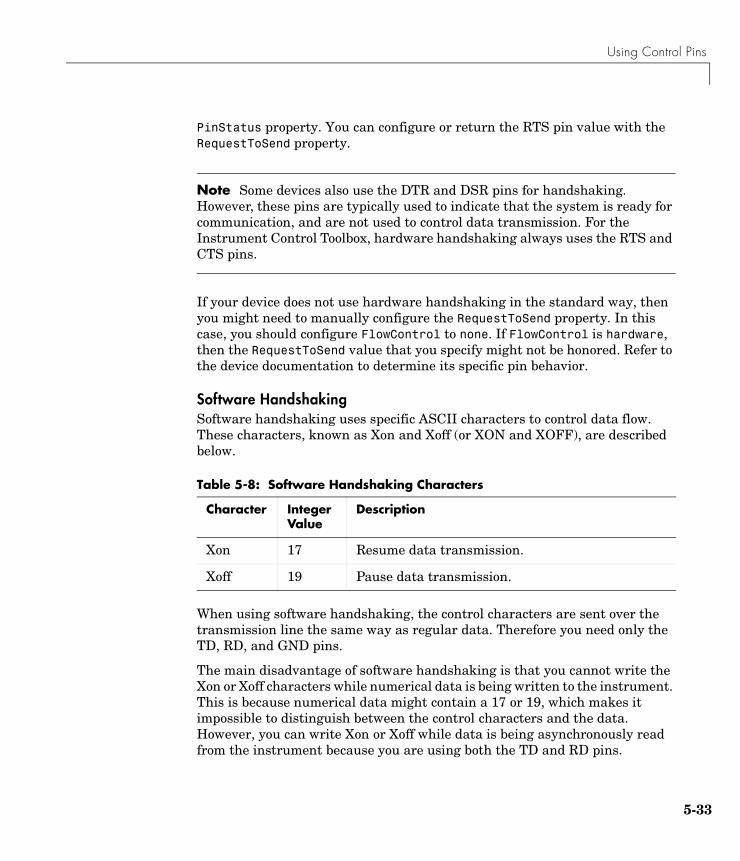
Using Control Pins
5-33
PinStatus property. You can configure or return the RTS pin value with the RequestToSend property.
Note Some devices also use the DTR and DSR pins for handshaking. However, these pins are typically used to indicate that the system is ready for communication, and are not used to control data transmission. For the Instrument Control Toolbox, hardware handshaking always uses the RTS and CTS pins.
If your device does not use hardware handshaking in the standard way, then you might need to manually configure the RequestToSend property. In this case, you should configure FlowControl to none. If FlowControl is hardware, then the RequestToSend value that you specify might not be honored. Refer to the device documentation to determine its specific pin behavior.
Software HandshakingSoftware handshaking uses specific ASCII characters to control data flow. These characters, known as Xon and Xoff (or XON and XOFF), are described below.
When using software handshaking, the control characters are sent over the transmission line the same way as regular data. Therefore you need only the TD, RD, and GND pins.
The main disadvantage of software handshaking is that you cannot write the Xon or Xoff characters while numerical data is being written to the instrument. This is because numerical data might contain a 17 or 19, which makes it impossible to distinguish between the control characters and the data. However, you can write Xon or Xoff while data is being asynchronously read from the instrument because you are using both the TD and RD pins.
Table 5-8: Software Handshaking Characters
Character Integer Value
Description
Xon 17 Resume data transmission.
Xoff 19 Pause data transmission.
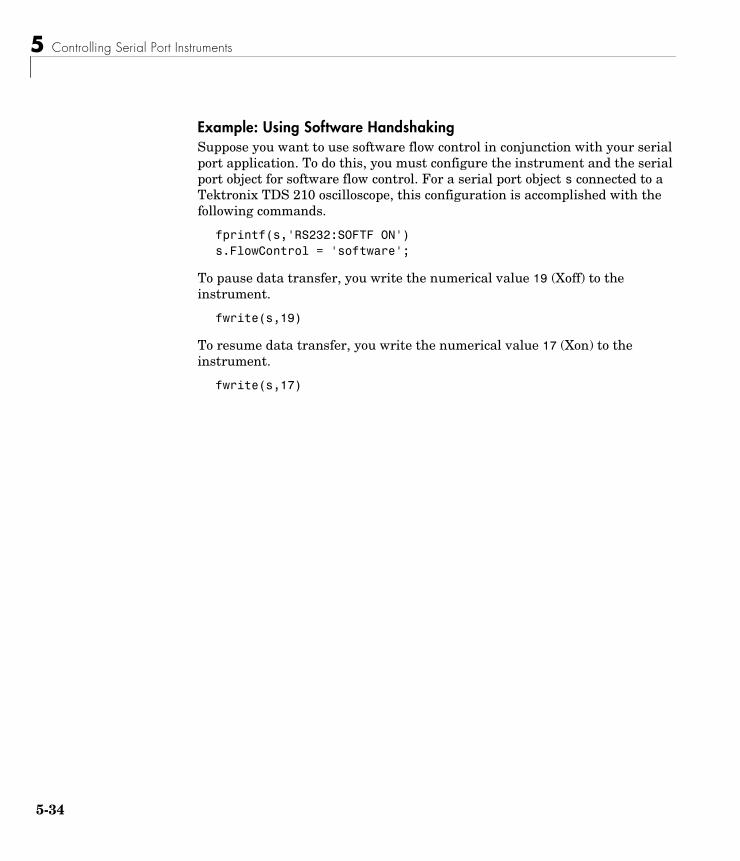
5 Controlling Serial Port Instruments
5-34
Example: Using Software HandshakingSuppose you want to use software flow control in conjunction with your serial port application. To do this, you must configure the instrument and the serial port object for software flow control. For a serial port object s connected to a Tektronix TDS 210 oscilloscope, this configuration is accomplished with the following commands.
fprintf(s,'RS232:SOFTF ON')s.FlowControl = 'software';
To pause data transfer, you write the numerical value 19 (Xoff) to the instrument.
fwrite(s,19)
To resume data transfer, you write the numerical value 17 (Xon) to the instrument.
fwrite(s,17)
6Controlling Instruments Using TCP/IP and UDP
This chapter describes specific issues related to controlling instruments that use the TCP/IP or UDP protocols. The sections are as follows.
TCP/IP and UDP Overview (p. 6-2)
A comparison between the TCP/IP and UDP protocols.
Creating a TCP/IP Object (p. 6-4)
The TCP/IP object establishes a connection between MATLAB and the remote host.
Creating a UDP Object (p. 6-8)
The UDP object establishes a connection between MATLAB and the remote host.
Writing and Reading Data (p. 6-12)
Interface-specific issues related to writing and reading data with a TCP/IP or UDP object.
Events and Callbacks (p. 6-19)
Enhance your instrument control application using events and callbacks.
6 Controlling Instruments Using TCP/IP and UDP
6-2
TCP/IP and UDP OverviewTransmission Control Protocol (TCP or TCP/IP) and User Datagram Protocol (UDP or UDP/IP) are both transport protocols layered on top of the Internet Protocol (IP). TCP/IP and UDP are compared below.
• Connection Versus Connectionless — TCP/IP is a connection-based protocol, while UDP is a connectionless protocol. In TCP/IP, the two ends of the communication link must be connected at all times during the communication. An application using UDP prepares a packet and sends it to the receiver's address without first checking to see if the receiver is ready to receive a packet. If the receiving end is not ready to receive a packet, the packet is lost.
• Stream Versus Packet — TCP/IP is a stream-oriented protocol, while UDP is a packet-oriented protocol. This means that TCP/IP is considered to be a long stream of data that is transmitted from one end of the connection to the other end, and another long stream of data flowing in the opposite direction. The TCP/IP stack is responsible for breaking the stream of data into packets and sending those packets while the stack at the other end is responsible for reassembling the packets into a data stream using information in the packet headers. UDP, on the other hand, is a packet-oriented protocol where the application itself divides the data into packets and sends them to the other end. The other end does not have to reassemble the data into a stream. Note, some applications might present the data as a stream when the underlying protocol is UDP. However, this is the layering of an additional protocol on top of UDP, and it is not something inherent in the UDP protocol itself.
• TCP/IP Is a Reliable Protocol, While UDP Is Unreliable — The packets that are sent by TCP/IP contain a unique sequence number. The starting sequence number is communicated to the other side at the beginning of communication. The receiver acknowledges each packet, and the acknowledgment contains the sequence number so that the sender knows which packet was acknowledged. This implies that any packets lost on the way can be retransmitted (the sender would know that they did not reach their destination because it had not received an acknowledgment). Also, packets that arrive out of sequence can be reassembled in the proper order by the receiver.
TCP/IP and UDP Overview
6-3
Further, timeouts can be established because the sender knows (from the first few packets) how long it takes on average for a packet to be sent and its acknowledgment received. UDP, on the other hand, sends the packets and does not keep track of them. Thus, if packets arrive out of sequence, or are lost in transmission, the receiving end (or the sending end) has no way of knowing.
Note that “unreliable” is used in the sense of “not guaranteed to succeed” as opposed to “will fail a lot of the time.” In practice, UDP is quite reliable as long as the receiving socket is active and is processing data as quickly as it arrives.
6 Controlling Instruments Using TCP/IP and UDP
6-4
Creating a TCP/IP ObjectYou create a TCP/IP object with the tcpip function. tcpip requires the name of the remote host as an input argument. In most cases, you need to specify the remote port value. If you do not specify the remote port, then 80 is used. As described in “Configuring Property Values” on page 2-9, you can also configure property values during object creation.
Each TCP/IP object is associated with one instrument. For example, to create a TCP/IP object for a Sony/Tektronix AWG520 Arbitrary Waveform Generator:
t = tcpip('sonytekawg.mathworks.com',4000);
Note that the port number is fixed and is found in the instrument's documentation.
The TCP/IP object t now exists in the MATLAB workspace. You can display the class of t with the whos command.
whos t Name Size Bytes Class
t 1x1 640 tcpip object
Grand total is 16 elements using 640 bytes
Once the TCP/IP object is created, the properties listed below are automatically assigned values. These general purpose properties provide descriptive information about the TCP/IP object based on the object type, the remote host, and the remote port.
Table 6-1: TCP/IP Descriptive Properties
Property Name Description
Name Specify a descriptive name for the TCP/IP object.
RemoteHost Specify the remote host.
RemotePort Specify the remote host port for the connection.
Type Indicate the object type.
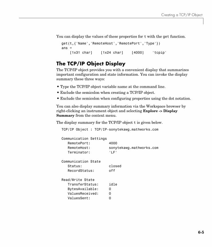
Creating a TCP/IP Object
6-5
You can display the values of these properties for t with the get function.
get(t,{'Name','RemoteHost','RemotePort','Type'})ans = [1x31 char] [1x24 char] [4000] 'tcpip'
The TCP/IP Object DisplayThe TCP/IP object provides you with a convenient display that summarizes important configuration and state information. You can invoke the display summary these three ways:
• Type the TCP/IP object variable name at the command line.
• Exclude the semicolon when creating a TCP/IP object.
• Exclude the semicolon when configuring properties using the dot notation.
You can also display summary information via the Workspace browser by right-clicking an instrument object and selecting Explore -> Display Summary from the context menu.
The display summary for the TCP/IP object t is given below.
TCP/IP Object : TCP/IP-sonytekawg.mathworks.com
Communication SettingsRemotePort: 4000RemoteHost: sonytekawg.mathworks.comTerminator: 'LF'
Communication StateStatus: closedRecordStatus: off
Read/Write StateTransferStatus: idleBytesAvailable: 0ValuesReceived: 0ValuesSent: 0
6 Controlling Instruments Using TCP/IP and UDP
6-6
Example: Server Drops the ConnectionThis example shows what happens when a TCP/IP object loses its connection with a remote server. The server is a Sony/Tektronix AWG520 Arbitrary Waveform Generator (AWG). Its address is sonytekawg.mathworks.com and its port is 4000. The AWG’s host IP address is 192.168.1.10 and is user configurable in the instrument. The associated host name is given by your network administrator. The port number is fixed and is found in the instrument's documentation.
The AWG can drop the connection because it is taken off line, it is powered down, and so on.
1 Create an instrument object — Create a TCP/IP object for the AWG.
t = tcpip('sonytekawg.mathworks.com', 4000);
2 Connect to the instrument — Connect to the remote instrument.
fopen(t)
3 Write and read data — Write a command to the instrument and read back the result.
fprintf(t,'*IDN?')fscanf(t)ans =SONY/TEK,AWG520,0,SCPI:95.0 OS:2.0 USR:2.0
Assume that the server drops the connection. If you attempt to read from the instrument, a timeout occurs and a warning is displayed.
fprintf(t,'*IDN?')fscanf(t)
Warning: A timeout occurred before the Terminator was reached.(Type "warning off instrument:fscanf:unsuccessfulRead" to suppress this warning.)ans = ''
Creating a TCP/IP Object
6-7
At this point, the object and the instrument are still connected.
get(t,'Status')ans =open
If you attempt to write to the instrument again, an error message is returned and the connection is automatically closed.
fprintf(t,'*IDN?')??? Error using ==> fprintfConnection closed by RemoteHost. Use FOPEN to connect to RemoteHost.
Note that if the TCP/IP object is connected to the local host, the warning message is not displayed. Instead, the error message is displayed following the next read operation after the connection is dropped.
4 Disconnect and clean up — When you no longer need t, you should disconnect it from the host, and remove it from memory and from the MATLAB workspace.
fclose(t)delete(t)clear t

6 Controlling Instruments Using TCP/IP and UDP
6-8
Creating a UDP ObjectYou create a UDP object with the udp function. udp does not require the name of the remote host as an input argument. However, if you are using the object to communicate with a specific instrument, you should specify the remote host and the port number. As described in “Configuring Property Values” on page 2-9, you can also configure property values during object creation.
For example, to create a UDP object associated with the remote host 127.0.0.1and the remote port 4012
u = udp('127.0.0.1',4012);
The UDP object u now exists in the MATLAB workspace. You can display the class of u with the whos command.
whos u Name Size Bytes Class
u 1x1 632 udp object
Grand total is 12 elements using 632 bytes
Once the UDP object is created, the properties listed below are automatically assigned values. These general purpose properties provide descriptive information about the UDP object based on the object type, the remote host, and the remote port.
Table 6-2: UDP Descriptive Properties
Property Name Description
Name Specify a descriptive name for the UDP object.
RemoteHost Specify the remote host.
RemotePort Specify the remote host port for the connection.
Type Indicate the object type.
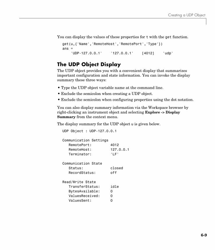
Creating a UDP Object
6-9
You can display the values of these properties for t with the get function.
get(u,{'Name','RemoteHost','RemotePort','Type'})ans = 'UDP-127.0.0.1' '127.0.0.1' [4012] 'udp'
The UDP Object DisplayThe UDP object provides you with a convenient display that summarizes important configuration and state information. You can invoke the display summary these three ways:
• Type the UDP object variable name at the command line.
• Exclude the semicolon when creating a UDP object.
• Exclude the semicolon when configuring properties using the dot notation.
You can also display summary information via the Workspace browser by right-clicking an instrument object and selecting Explore -> Display Summary from the context menu.
The display summary for the UDP object u is given below.
UDP Object : UDP-127.0.0.1
Communication Settings RemotePort: 4012RemoteHost: 127.0.0.1Terminator: 'LF'
Communication State Status: closedRecordStatus: off
Read/Write State TransferStatus: idleBytesAvailable: 0ValuesReceived: 0ValuesSent: 0
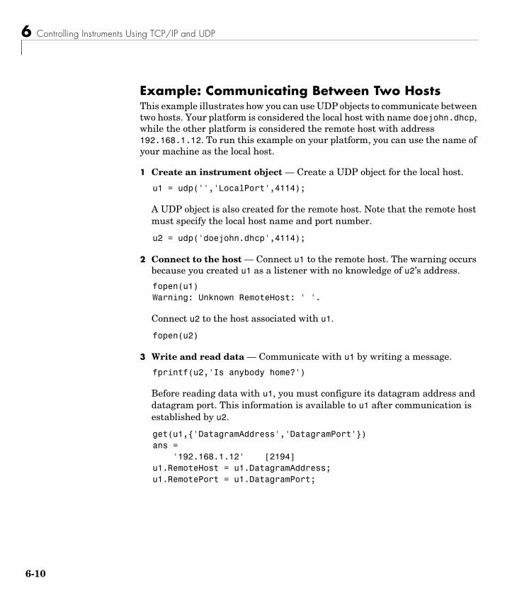
6 Controlling Instruments Using TCP/IP and UDP
6-10
Example: Communicating Between Two HostsThis example illustrates how you can use UDP objects to communicate between two hosts. Your platform is considered the local host with name doejohn.dhcp, while the other platform is considered the remote host with address 192.168.1.12. To run this example on your platform, you can use the name of your machine as the local host.
1 Create an instrument object — Create a UDP object for the local host.
u1 = udp('','LocalPort',4114);
A UDP object is also created for the remote host. Note that the remote host must specify the local host name and port number.
u2 = udp('doejohn.dhcp',4114);
2 Connect to the host — Connect u1 to the remote host. The warning occurs because you created u1 as a listener with no knowledge of u2’s address.
fopen(u1)Warning: Unknown RemoteHost: ' '.
Connect u2 to the host associated with u1.
fopen(u2)
3 Write and read data — Communicate with u1 by writing a message.
fprintf(u2,'Is anybody home?')
Before reading data with u1, you must configure its datagram address and datagram port. This information is available to u1 after communication is established by u2.
get(u1,{'DatagramAddress','DatagramPort'})ans = '192.168.1.12' [2194]u1.RemoteHost = u1.DatagramAddress;u1.RemotePort = u1.DatagramPort;
Creating a UDP Object
6-11
You can now read the message.
fscanf(u1)ans =Is anybody home?
You can also write a message to u2.
fprintf(u2,'I''m here!')
4 Disconnect and clean up — When you no longer need u1, you should disconnect it from the host, and remove it from memory and from the MATLAB workspace.
fclose(u1)delete(u1)clear u1
6 Controlling Instruments Using TCP/IP and UDP
6-12
Writing and Reading DataThis section describes interface-specific issues related to writing and reading data with TCP/IP and UDP objects. Topics include
• The rules for completing write and read operations
• Examples that illustrate writing and reading text data and binary data
For a general overview about writing and reading data, as well as a list of all associated functions and properties, refer to “Writing and Reading Data” on page 2-12.
Rules for Completing Write and Read OperationsThe rules for completing synchronous and asynchronous read and write operations are described below.
Completing Write OperationsA write operation using fprintf or fwrite completes when one of these conditions is satisfied:
• The specified data is written.
• The time specified by the Timeout property passes.
In addition to these rules, you can stop an asynchronous write operation at any time with the stopasync function.
A text command is processed by the instrument only when it receives the required terminator. For TCP/IP and UDP objects, each occurrence of \n in the ASCII command is replaced with the Terminator property value. Because the default format for fprintf is %s\n, all commands written to the instrument will end with the Terminator value. The default value of Terminator is the line feed character. The terminator required by your instrument will be described in its documentation.
Writing and Reading Data
6-13
Completing Read OperationsA read operation with fgetl, fgets, fscanf, or readasync completes when one of these conditions is satisfied:
• The terminator specified by the Terminator property is read. For UDP objects, DatagramTerminateMode must be off.
• The time specified by the Timeout property passes.
• The input buffer is filled.
• The specified number of values is read (fscanf and readasync only). For UDP objects, DatagramTerminateMode must be off.
• A datagram is received (for UDP objects, only when DatagramTerminateMode is on).
A read operation with fread completes when one of these conditions is satisfied:
• The time specified by the Timeout property passes.
• The input buffer is filled.
• The specified number of values is read. For UDP objects, DatagramTerminateMode must be off.
• A datagram is received (for UDP objects, only when DatagramTerminateMode is on).
In addition to these rules, you can stop an asynchronous read operation at any time with the stopasync function.
Example: Writing and Reading Data with a TCP/IP ObjectThis example illustrates how to use text and binary read and write operations with a TCP/IP object connected to a remote instrument. In this example, you create a vector of waveform data in MATLAB, upload the data to the instrument, and then read back the waveform.
The instrument is a Sony/Tektronix AWG520 Arbitrary Waveform Generator (AWG). Its address is sonytekawg.mathworks.com and its port is 4000. The AWG's host IP address is 192.168.1.10 and is user configurable in the instrument. The associated host name is given by your network administrator. The port number is fixed and is found in the instrument's documentation.
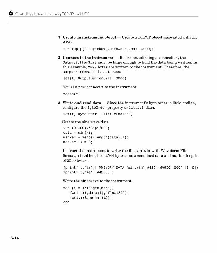
6 Controlling Instruments Using TCP/IP and UDP
6-14
1 Create an instrument object — Create a TCP/IP object associated with the AWG.
t = tcpip('sonytekawg.mathworks.com',4000);
2 Connect to the instrument — Before establishing a connection, the OutputBufferSize must be large enough to hold the data being written. In this example, 2577 bytes are written to the instrument. Therefore, the OutputBufferSize is set to 3000.
set(t,'OutputBufferSize',3000)
You can now connect t to the instrument.
fopen(t)
3 Write and read data — Since the instrument's byte order is little-endian, configure the ByteOrder property to littleEndian.
set(t,'ByteOrder','littleEndian')
Create the sine wave data.x = (0:499).*8*pi/500;data = sin(x);marker = zeros(length(data),1);marker(1) = 3;
Instruct the instrument to write the file sin.wfm with Waveform File format, a total length of 2544 bytes, and a combined data and marker length of 2500 bytes.
fprintf(t,'%s',['MMEMORY:DATA "sin.wfm",#42544MAGIC 1000' 13 10])fprintf(t,'%s','#42500')
Write the sine wave to the instrument.
for (i = 1:length(data)),fwrite(t,data(i),'float32');fwrite(t,marker(i));
end
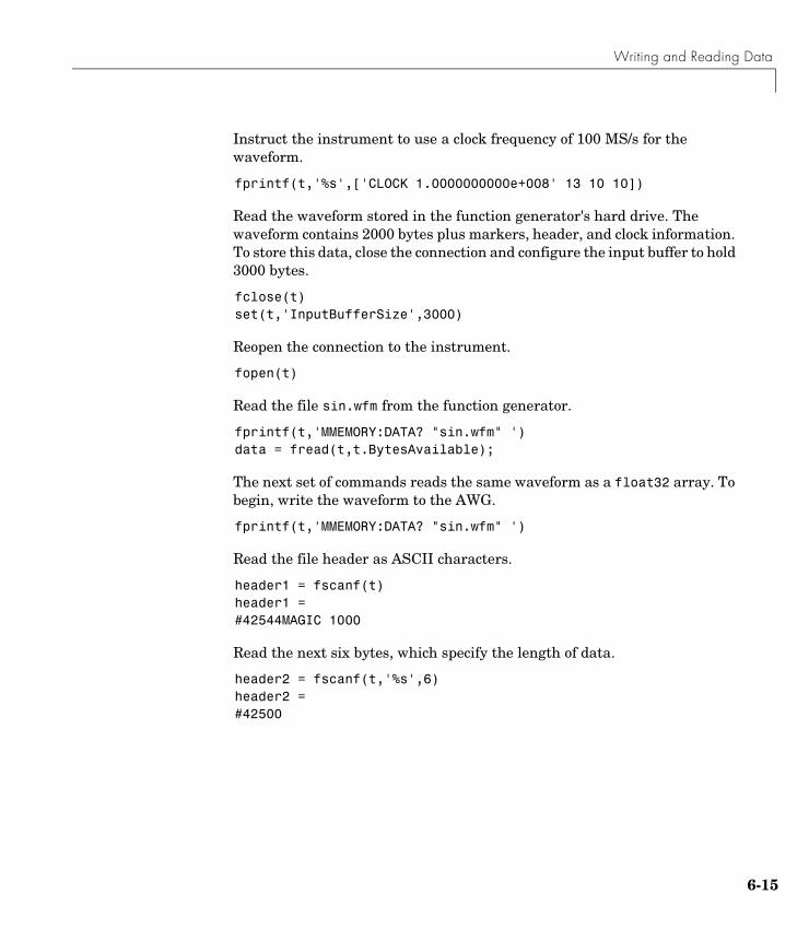
Writing and Reading Data
6-15
Instruct the instrument to use a clock frequency of 100 MS/s for the waveform.
fprintf(t,'%s',['CLOCK 1.0000000000e+008' 13 10 10])
Read the waveform stored in the function generator's hard drive. The waveform contains 2000 bytes plus markers, header, and clock information. To store this data, close the connection and configure the input buffer to hold 3000 bytes.
fclose(t)set(t,'InputBufferSize',3000)
Reopen the connection to the instrument.
fopen(t)
Read the file sin.wfm from the function generator.
fprintf(t,'MMEMORY:DATA? "sin.wfm" ')data = fread(t,t.BytesAvailable);
The next set of commands reads the same waveform as a float32 array. To begin, write the waveform to the AWG.
fprintf(t,'MMEMORY:DATA? "sin.wfm" ')
Read the file header as ASCII characters.
header1 = fscanf(t)header1 =#42544MAGIC 1000
Read the next six bytes, which specify the length of data.
header2 = fscanf(t,'%s',6)header2 =#42500
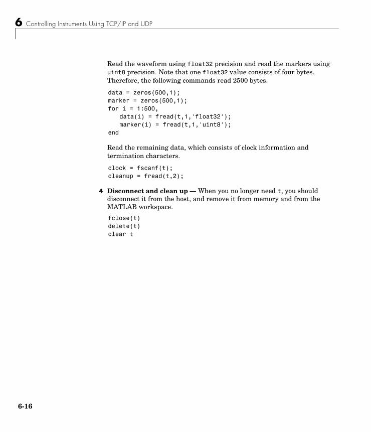
6 Controlling Instruments Using TCP/IP and UDP
6-16
Read the waveform using float32 precision and read the markers using uint8 precision. Note that one float32 value consists of four bytes. Therefore, the following commands read 2500 bytes.
data = zeros(500,1);marker = zeros(500,1);for i = 1:500,
data(i) = fread(t,1,'float32');marker(i) = fread(t,1,'uint8');
end
Read the remaining data, which consists of clock information and termination characters.
clock = fscanf(t);cleanup = fread(t,2);
4 Disconnect and clean up — When you no longer need t, you should disconnect it from the host, and remove it from memory and from the MATLAB workspace.
fclose(t)delete(t)clear t
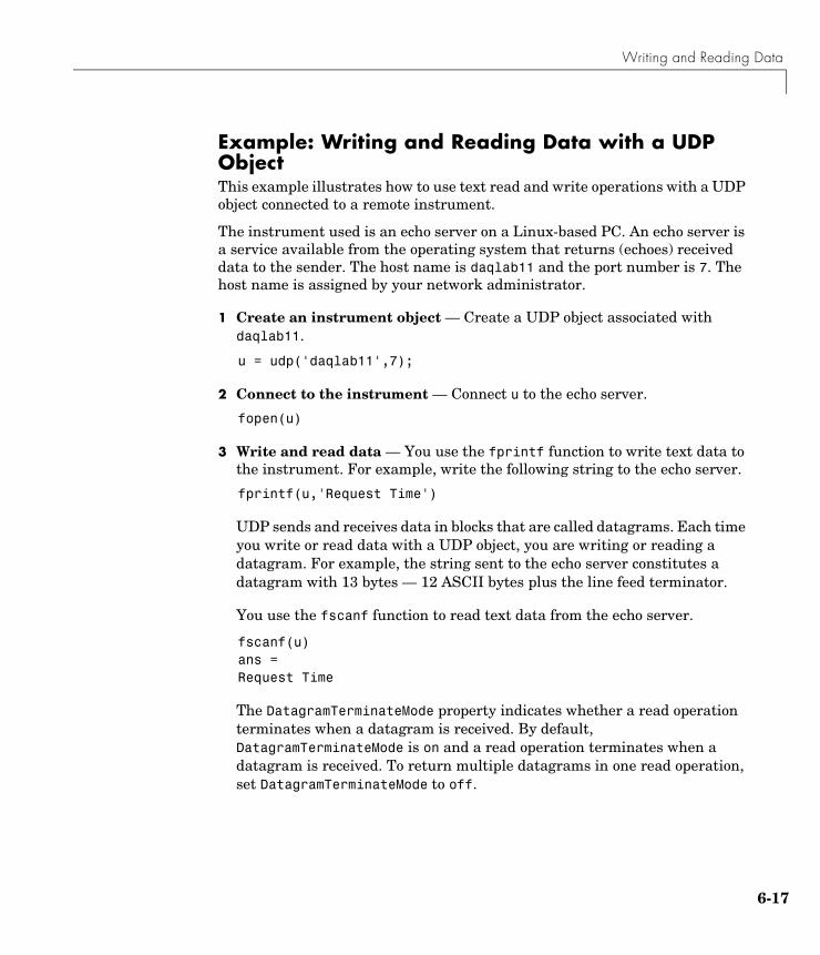
Writing and Reading Data
6-17
Example: Writing and Reading Data with a UDP ObjectThis example illustrates how to use text read and write operations with a UDP object connected to a remote instrument.
The instrument used is an echo server on a Linux-based PC. An echo server is a service available from the operating system that returns (echoes) received data to the sender. The host name is daqlab11 and the port number is 7. The host name is assigned by your network administrator.
1 Create an instrument object — Create a UDP object associated with daqlab11.
u = udp('daqlab11',7);
2 Connect to the instrument — Connect u to the echo server.
fopen(u)
3 Write and read data — You use the fprintf function to write text data to the instrument. For example, write the following string to the echo server.
fprintf(u,'Request Time')
UDP sends and receives data in blocks that are called datagrams. Each time you write or read data with a UDP object, you are writing or reading a datagram. For example, the string sent to the echo server constitutes a datagram with 13 bytes — 12 ASCII bytes plus the line feed terminator.
You use the fscanf function to read text data from the echo server.
fscanf(u)ans =Request Time
The DatagramTerminateMode property indicates whether a read operation terminates when a datagram is received. By default, DatagramTerminateMode is on and a read operation terminates when a datagram is received. To return multiple datagrams in one read operation, set DatagramTerminateMode to off.
6 Controlling Instruments Using TCP/IP and UDP
6-18
The following commands write two datagrams. Note that only the second datagram sends the terminator character.
fprintf(u,'%s','Request Time')fprintf(u,'%s\n','Request Time')
Since DatagramTerminateMode is off, fscanf reads across datagram boundaries until the terminator character is received.
set(u,'DatagramTerminateMode','off')data = fscanf(u)data =Request TimeRequest Time
4 Disconnect and clean up — When you no longer need u, you should disconnect it from the host, and remove it from memory and from the MATLAB workspace.
fclose(u)delete(u)clear u
Events and Callbacks
6-19
Events and CallbacksThis section describes interface-specific issues related to using events and callbacks with a TCP/IP or UDP object. Topics include
• Event types and callback properties
• Storing event information
• An example that uses the datagram-received event and the instrcallback function
For a general overview of events and callbacks, including how to create and execute callback functions, refer to “Events and Callbacks” on page 3-30.
Event Types and Callback PropertiesThe event types and associated callback properties supported by TCP/IP and UDP objects are listed below.
The datagram-received event is described below. For a description of the other event types, refer to “Event Types and Callback Properties” on page 3-31.
Table 6-3: TCP/IP and UDP Event Types and Callback Properties
Event Type Associated Properties
Bytes available BytesAvailableFcn
BytesAvailableFcnCount
BytesAvailableFcnMode
Datagram received DatagramReceivedFcn (UDP objects only)
Error ErrorFcn
Output empty OutputEmptyFcn
Timer TimerFcn
TimerPeriod
6 Controlling Instruments Using TCP/IP and UDP
6-20
Datagram-received Event. A datagram-received event is generated immediately after a complete datagram is received in the input buffer.
This event executes the callback function specified for the DatagramReceivedFcn property. It can be generated for both synchronous and asynchronous read operations.
Storing Event InformationYou can store event information in a callback function or in a record file. Event information stored in a callback function uses two fields: Type and Data. The Type field contains the event type, while the Data field contains event-specific information. As described in “Creating and Executing Callback Functions” on page 3-33, these two fields are associated with a structure that you define in the callback function header. Refer to “Debugging: Recording Information to Disk” on page 7-5 to learn about storing event information in a record file.
The event types and the values for the Type and Data fields are given below.
Table 6-4: TCP/IP and UDP Event Information
Event Type Field Field Value
Bytes available Type BytesAvailable
Data.AbsTime day-month-year hour:minute:second
Datagram received
Type DatagramReceived
Data.AbsTime day-month-year hour:minute:second
Error Type Error
Data.AbsTime day-month-year hour:minute:second
Data.Message An error string
Output empty Type OutputEmpty
Data.AbsTime day-month-year hour:minute:second
Timer Type Timer
Data.AbsTime day-month-year hour:minute:second
Events and Callbacks
6-21
The Data field values are described below.
The AbsTime Field. AbsTime is defined for all events, and indicates the absolute time the event occurred. The absolute time is returned using the MATLAB clock format.
day-month-year hour:minute:second
The Message Field. Message is used by the error event to store the descriptive message that is generated when an error occurs.
Example: Using Events and CallbacksThis example extends “Example: Communicating Between Two Hosts” on page 6-10 to include a datagram received callback. The callback function is instrcallback, which displays information to the command line indicating that a datagram has been received.
The following command configures the callback for the UDP object u1.
u1.DatagramReceivedFcn = @instrcallback;
When a datagram is received, the following message is displayed.
DatagramReceived event occurred at 10:26:20 for the object: UDP-192.168.1.12.17 bytes were received from address 192.168.1.12, port 2194.

6 Controlling Instruments Using TCP/IP and UDP
6-22
7Saving and Loading the Session
This chapter describes how to save and load information associated with an instrument control session. The sections are as follows.
Saving and Loading Instrument Objects (p. 7-2)
Save instrument objects and their associated property values to disk as an M-file or as a MAT-file.
Debugging: Recording Information to Disk (p. 7-5)
Save information to disk as a text file. The saved information includes the data transferred to and from the instrument, and event information.
7 Saving and Loading the Session
7-2
Saving and Loading Instrument ObjectsYou can save an instrument object to disk using two possible formats:
• As an M-file using the obj2mfile function
• As a MAT-file using the save command
You can also save data transferred between the object and the instrument using these two functions. However, it is easier to use the record function for this purpose as described in “Debugging: Recording Information to Disk” on page 7-5.
Saving Instrument Objects to an M-FileYou can save an instrument object to an M-file using the obj2mfile function. obj2mfile provides you with these options:
• Save all property values or save only those property values that differ from their default values.
Read-only property values are not saved. Therefore, read-only properties use their default values when you load the instrument object into the MATLAB workspace. To determine if a property is read-only, use the propinfo function or examine the property reference pages.
• Save property values using the set syntax or the dot notation.
If the UserData property is not empty, or if a callback property is set to a cell array of values or a function handle, then the data stored in these properties is written to a MAT-file when the instrument object is saved. The MAT-file has the same name as the M-file containing the instrument object code.
For example, suppose you create the GPIB object g, return instrument identification information to the variable out, and store out in the UserData property.
g = gpib('ni',0,1);g.Tag = 'My GPIB object';fopen(g)cmd = '*IDN?';fprintf(g,cmd)out = fscanf(g);g.UserData = out;
Saving and Loading Instrument Objects
7-3
The following command saves g and the modified property values to the M-file mygpib.m. Because the UserData property is not empty, its value is automatically written to the MAT-file mygpib.mat.
obj2mfile(g,'mygpib.m');
Use the type command to display mygpib.m at the command line.
Loading the Instrument ObjectTo load an instrument object that was saved as an M-file into the MATLAB workspace, type the name of the M-file at the command line. For example, to load g from the M-file mygpib.m:
g = mygpib
The display summary for g is shown below. Note that the read-only properties such as Status, BytesAvailable, ValuesReceived, and ValuesSent are restored to their default values.
GPIB Object Using NI Adaptor : GPIB0-1
Communication Address BoardIndex: 0PrimaryAddress: 1SecondaryAddress: 0
Communication State Status: closedRecordStatus: off
Read/Write State TransferStatus: idleBytesAvailable: 0ValuesReceived: 0ValuesSent: 0
When loading g into the workspace, the MAT-file mygpib.mat is automatically loaded and the UserData property value is restored.
g.UserDataans =TEKTRONIX,TDS 210,0,CF:91.1CT FV:v1.16 TDS2CM:CMV:v1.04
7 Saving and Loading the Session
7-4
Saving Objects to a MAT-FileYou can save an instrument object to a MAT-file just as you would any workspace variable — using the save command. For example, to save the GPIB object g, and the variables cmd and out defined in the preceding section to the MAT-file mygpib1.mat:
save mygpib1 g cmd out
Read-only property values are not saved. Therefore, read-only properties use their default values when you load the instrument object into the MATLAB workspace. To determine if a property is read-only, use the propinfo function or examine the property reference pages.
Loading the Instrument ObjectTo load an instrument object that was saved to a MAT-file into the MATLAB workspace, use the load command. For example, to load g, cmd, and out from MAT-file mygpib1.mat:
load mygpib1
The display summary for g is shown below. Note that the read-only properties such as Status, BytesAvailable, ValuesReceived, and ValuesSent are restored to their default values.
GPIB Object Using NI Adaptor : GPIB0-1
Communication Address BoardIndex: 0PrimaryAddress: 1SecondaryAddress: 0
Communication State Status: closedRecordStatus: off
Read/Write State TransferStatus: idleBytesAvailable: 0ValuesReceived: 0ValuesSent: 0
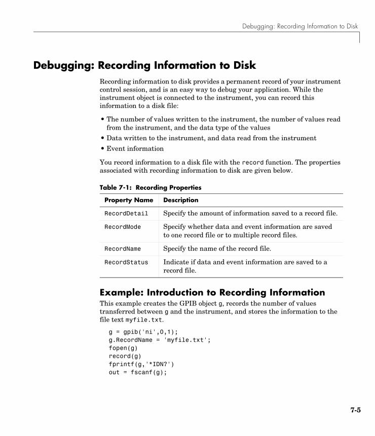
Debugging: Recording Information to Disk
7-5
Debugging: Recording Information to DiskRecording information to disk provides a permanent record of your instrument control session, and is an easy way to debug your application. While the instrument object is connected to the instrument, you can record this information to a disk file:
• The number of values written to the instrument, the number of values read from the instrument, and the data type of the values
• Data written to the instrument, and data read from the instrument
• Event information
You record information to a disk file with the record function. The properties associated with recording information to disk are given below.
Example: Introduction to Recording InformationThis example creates the GPIB object g, records the number of values transferred between g and the instrument, and stores the information to the file text myfile.txt.
g = gpib('ni',0,1);g.RecordName = 'myfile.txt';fopen(g)record(g)fprintf(g,'*IDN?')out = fscanf(g);
Table 7-1: Recording Properties
Property Name Description
RecordDetail Specify the amount of information saved to a record file.
RecordMode Specify whether data and event information are saved to one record file or to multiple record files.
RecordName Specify the name of the record file.
RecordStatus Indicate if data and event information are saved to a record file.
7 Saving and Loading the Session
7-6
End the instrument control session.
fclose(g)delete(g)clear g
Use the type command to display myfile.txt at the command line.
Creating Multiple Record FilesWhen you initiate recording with the record function, the RecordMode property determines if a new record file is created or if new information is appended to an existing record file.
You can configure RecordMode to overwrite, append, or index. If RecordMode is overwrite, then the record file is overwritten each time recording is initiated. If RecordMode is append, then the new information is appended to the file specified by RecordName. If RecordMode is index, a different disk file is created each time recording is initiated. The rules for specifying a record filename are discussed in the next section.
Specifying a FilenameYou specify the name of the record file with the RecordName property. You can specify any value for RecordName, including a directory path, provided the filename is supported by your operating system. Additionally, if RecordMode is index, then the filename follows these rules:
• Indexed filenames are identified by a number. This number precedes the filename extension and is increased by 1 for successive record files.
• If no number is specified as part of the initial filename, then the first record file does not have a number associated with it. For example, if RecordName is myfile.txt, then myfile.txt is the name of the first record file, myfile01.txt is the name of the second record file, and so on.
• RecordName is updated after the record file is closed.
• If the specified filename already exists, then the existing file is overwritten.
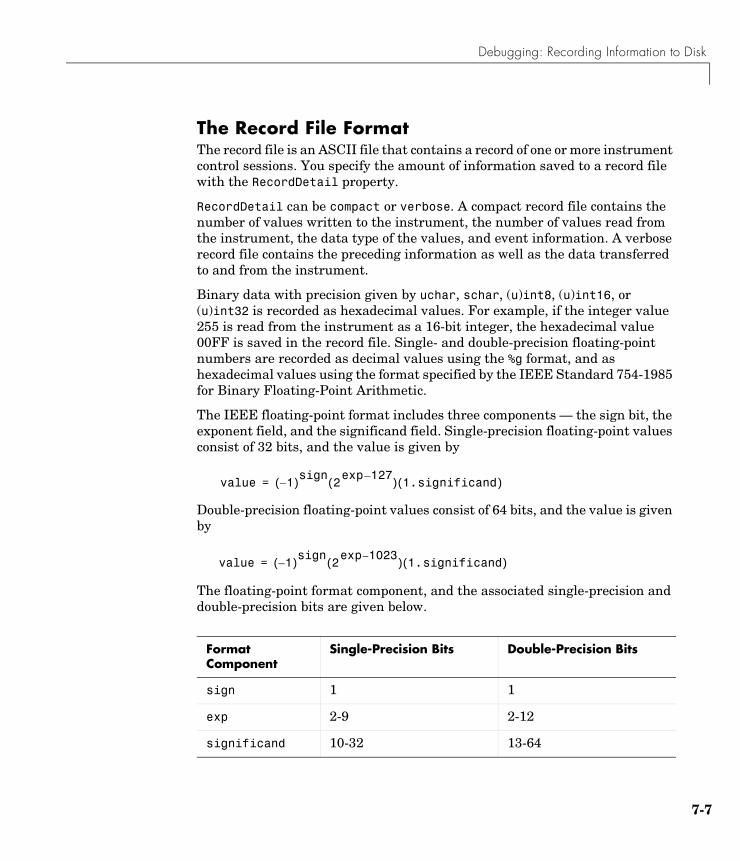
Debugging: Recording Information to Disk
7-7
The Record File FormatThe record file is an ASCII file that contains a record of one or more instrument control sessions. You specify the amount of information saved to a record file with the RecordDetail property.
RecordDetail can be compact or verbose. A compact record file contains the number of values written to the instrument, the number of values read from the instrument, the data type of the values, and event information. A verbose record file contains the preceding information as well as the data transferred to and from the instrument.
Binary data with precision given by uchar, schar, (u)int8, (u)int16, or (u)int32 is recorded as hexadecimal values. For example, if the integer value 255 is read from the instrument as a 16-bit integer, the hexadecimal value 00FF is saved in the record file. Single- and double-precision floating-point numbers are recorded as decimal values using the %g format, and as hexadecimal values using the format specified by the IEEE Standard 754-1985 for Binary Floating-Point Arithmetic.
The IEEE floating-point format includes three components — the sign bit, the exponent field, and the significand field. Single-precision floating-point values consist of 32 bits, and the value is given by
Double-precision floating-point values consist of 64 bits, and the value is given by
The floating-point format component, and the associated single-precision and double-precision bits are given below.
Format Component
Single-Precision Bits Double-Precision Bits
sign 1 1
exp 2-9 2-12
significand 10-32 13-64
value 1–( )sign 2127–exp( ) 1.significand( )=
value 1–( )sign 21023–exp( ) 1.significand( )=

7 Saving and Loading the Session
7-8
For example, suppose you record the decimal value 4.25 using the single-precision format. The record file stores 4.25 as the hex value 40880000, which is calculated from the IEEE single-precision floating-point format. To reconstruct the original value, convert the hex value to a decimal value using hex2dec:
dval = hex2dec('40880000')dval = 1.082654720000000e+009
Convert the decimal value to a binary value using dec2bin:
bval = dec2bin(dval,32)bval =01000000100010000000000000000000
The interpretation of bval is given by the preceding table. The left most bit indicates the value is positive because (-1)0 = 1. The next 8 bits correspond to the exponent, which is given by
exp = bval(2:9)exp =10000001
The decimal value of exp is 27+20 = 129. The remaining bits correspond to the significand, which is given by
significand = bval(10:32)significand =00010000000000000000000
The decimal value of significand is 2-4 = 0.0625. You reconstruct the original value by plugging the decimal values of exp and significand into the formula for IEEE singles:
value = (-1)0(2129 - 127)(1.0625)value = 4.25
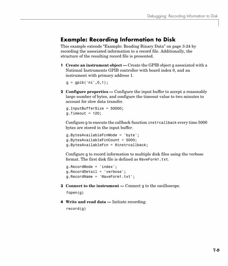
Debugging: Recording Information to Disk
7-9
Example: Recording Information to DiskThis example extends “Example: Reading Binary Data” on page 3-24 by recording the associated information to a record file. Additionally, the structure of the resulting record file is presented.
1 Create an instrument object — Create the GPIB object g associated with a National Instruments GPIB controller with board index 0, and an instrument with primary address 1.
g = gpib('ni',0,1);
2 Configure properties — Configure the input buffer to accept a reasonably large number of bytes, and configure the timeout value to two minutes to account for slow data transfer.
g.InputBufferSize = 50000;g.Timeout = 120;
Configure g to execute the callback function instrcallback every time 5000 bytes are stored in the input buffer.
g.BytesAvailableFcnMode = 'byte';g.BytesAvailableFcnCount = 5000;g.BytesAvailableFcn = @instrcallback;
Configure g to record information to multiple disk files using the verbose format. The first disk file is defined as WaveForm1.txt.
g.RecordMode = 'index';g.RecordDetail = 'verbose';g.RecordName = 'WaveForm1.txt';
3 Connect to the instrument — Connect g to the oscilloscope.
fopen(g)
4 Write and read data — Initiate recording.
record(g)
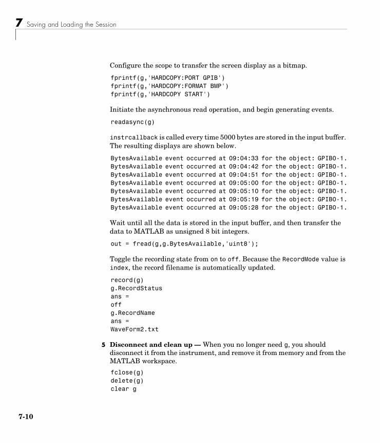
7 Saving and Loading the Session
7-10
Configure the scope to transfer the screen display as a bitmap.
fprintf(g,'HARDCOPY:PORT GPIB')fprintf(g,'HARDCOPY:FORMAT BMP')fprintf(g,'HARDCOPY START')
Initiate the asynchronous read operation, and begin generating events.
readasync(g)
instrcallback is called every time 5000 bytes are stored in the input buffer. The resulting displays are shown below.
BytesAvailable event occurred at 09:04:33 for the object: GPIB0-1.BytesAvailable event occurred at 09:04:42 for the object: GPIB0-1.BytesAvailable event occurred at 09:04:51 for the object: GPIB0-1.BytesAvailable event occurred at 09:05:00 for the object: GPIB0-1.BytesAvailable event occurred at 09:05:10 for the object: GPIB0-1.BytesAvailable event occurred at 09:05:19 for the object: GPIB0-1.BytesAvailable event occurred at 09:05:28 for the object: GPIB0-1.
Wait until all the data is stored in the input buffer, and then transfer the data to MATLAB as unsigned 8 bit integers.
out = fread(g,g.BytesAvailable,'uint8');
Toggle the recording state from on to off. Because the RecordMode value is index, the record filename is automatically updated.
record(g)g.RecordStatusans =offg.RecordNameans =WaveForm2.txt
5 Disconnect and clean up — When you no longer need g, you should disconnect it from the instrument, and remove it from memory and from the MATLAB workspace.
fclose(g)delete(g)clear g
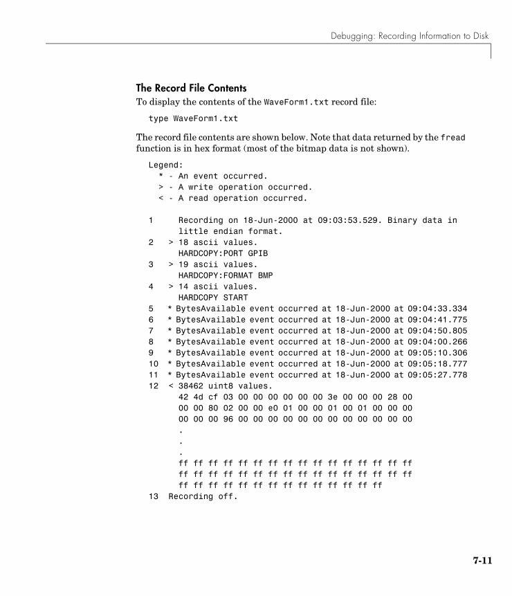
Debugging: Recording Information to Disk
7-11
The Record File ContentsTo display the contents of the WaveForm1.txt record file:
type WaveForm1.txt
The record file contents are shown below. Note that data returned by the fread function is in hex format (most of the bitmap data is not shown).
Legend: * - An event occurred. > - A write operation occurred. < - A read operation occurred. 1 Recording on 18-Jun-2000 at 09:03:53.529. Binary data in
little endian format.2 > 18 ascii values.
HARDCOPY:PORT GPIB3 > 19 ascii values.
HARDCOPY:FORMAT BMP4 > 14 ascii values.
HARDCOPY START5 * BytesAvailable event occurred at 18-Jun-2000 at 09:04:33.3346 * BytesAvailable event occurred at 18-Jun-2000 at 09:04:41.7757 * BytesAvailable event occurred at 18-Jun-2000 at 09:04:50.8058 * BytesAvailable event occurred at 18-Jun-2000 at 09:04:00.2669 * BytesAvailable event occurred at 18-Jun-2000 at 09:05:10.30610 * BytesAvailable event occurred at 18-Jun-2000 at 09:05:18.77711 * BytesAvailable event occurred at 18-Jun-2000 at 09:05:27.77812 < 38462 uint8 values.
42 4d cf 03 00 00 00 00 00 00 3e 00 00 00 28 00 00 00 80 02 00 00 e0 01 00 00 01 00 01 00 00 00 00 00 00 96 00 00 00 00 00 00 00 00 00 00 00 00 ...ff ff ff ff ff ff ff ff ff ff ff ff ff ff ff ff ff ff ff ff ff ff ff ff ff ff ff ff ff ff ff ffff ff ff ff ff ff ff ff ff ff ff ff ff ff
13 Recording off.

7 Saving and Loading the Session
7-12
8
Function Reference
This chapter describes the toolbox M-file functions that you use directly. A number of other M-file helper functions are provided with this toolbox to support the functions listed below. These helper functions are not documented because they are not intended for direct use.
Functions – By Category (p. 8-2)
Contains a series of tables that group functions by category
Functions – Alphabetical List (p. 8-7)
Lists all the functions alphabetically
8
8-2
Functions – By CategoryThis section contains brief descriptions of all toolbox functions. The functions are divided into these two groups:
• Base functions
• Object-specific functions
Base FunctionsBase functions apply to all supported instrument objects (GPIB, VISA-VXI, and so on). For example, the fscanf function is supported for all instrument objects. The base functions are organized into the following categories.
Creating Instrument Objects
State Change
Reading and Writing Data
gpib Create a GPIB object
serial Create a serial port object
tcpip Create a TCP/IP object
udp Create a UDP object
visa Create a VISA object
fclose Disconnect an instrument object from the instrument
fopen Connect an instrument object to the instrument
record Record data and event information to a file
binblockread Read binblock data from the instrument
binblockwrite Write binblock data to the instrument
fgetl Read one line of text from the instrument and discard the terminator

Functions – By Category
8-3
Getting and Setting Properties
Getting Information and Help
Graphical Tools
fgets Read one line of text from the instrument and include the terminator
fprintf Write text to the instrument
fread Read binary data from the instrument
fscanf Read data from the instrument, and format as text
fwrite Write binary data to the instrument
query Write text to the instrument, and read data from the instrument
readasync Read data asynchronously from the instrument
scanstr Read data from the instrument, format as text, and parse
stopasync Stop asynchronous read and write operations
get Return instrument object properties
inspect Open Property Inspector
set Configure or display instrument object properties
instrhelp Return instrument object function and property help
instrhwinfo Return information about available hardware
instrschool Interface for displaying toolbox tutorials
propinfo Return instrument object property information
instrcomm Graphical tool for communicating with an instrument using text data
instrcreate Graphical tool for creating and configuring an instrument object
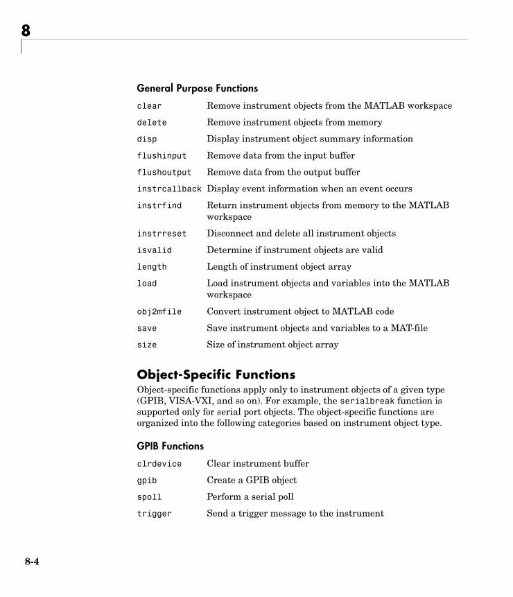
8
8-4
General Purpose Functions
Object-Specific FunctionsObject-specific functions apply only to instrument objects of a given type (GPIB, VISA-VXI, and so on). For example, the serialbreak function is supported only for serial port objects. The object-specific functions are organized into the following categories based on instrument object type.
GPIB Functions
clear Remove instrument objects from the MATLAB workspace
delete Remove instrument objects from memory
disp Display instrument object summary information
flushinput Remove data from the input buffer
flushoutput Remove data from the output buffer
instrcallback Display event information when an event occurs
instrfind Return instrument objects from memory to the MATLAB workspace
instrreset Disconnect and delete all instrument objects
isvalid Determine if instrument objects are valid
length Length of instrument object array
load Load instrument objects and variables into the MATLAB workspace
obj2mfile Convert instrument object to MATLAB code
save Save instrument objects and variables to a MAT-file
size Size of instrument object array
clrdevice Clear instrument buffer
gpib Create a GPIB object
spoll Perform a serial poll
trigger Send a trigger message to the instrument

Functions – By Category
8-5
Serial Port Functions
TCP/IP Functions
UDP Functions
VISA-GPIB Functions
VISA-VXI Functions
freeserial Release MATLAB's hold on a serial port
serial Create a serial port object
serialbreak Send a break to the instrument
echotcpip Start or stop a TCP/IP echo server
tcpip Create a TCP/IP object
resolvehost Return network name or network address
echoudp Start or stop a UDP echo server
udp Create a UDP object
clrdevice Clear instrument buffer
trigger Send a trigger message to the instrument
visa Create a VISA object
clrdevice Clear instrument buffer
memmap Map memory for low-level memory read and write operations
mempeek Low-level memory read from VXI register
mempoke Low-level memory write to VXI register
memread High-level memory read from VXI register
memunmap Unmap memory for low-level memory read and write operations
memwrite High-level memory write to VXI register
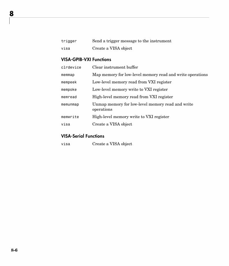
8
8-6
VISA-GPIB-VXI Functions
VISA-Serial Functions
trigger Send a trigger message to the instrument
visa Create a VISA object
clrdevice Clear instrument buffer
memmap Map memory for low-level memory read and write operations
mempeek Low-level memory read from VXI register
mempoke Low-level memory write to VXI register
memread High-level memory read from VXI register
memunmap Unmap memory for low-level memory read and write operations
memwrite High-level memory write to VXI register
visa Create a VISA object
visa Create a VISA object
Functions – Alphabetical List
8-7
Functions – Alphabetical ListThis section contains detailed descriptions of all toolbox functions. Each function reference page contains some or all of this information:
• The function name
• The function purpose
• The function syntax
All valid input argument and output argument combinations are shown. In some cases, an ellipsis (. . .) is used for the input arguments. This means that all preceding input argument combinations are valid for the specified output argument(s).
• A description of each argument
• A description of each function syntax
• Additional remarks about usage
• An example of usage
• Related functions and properties
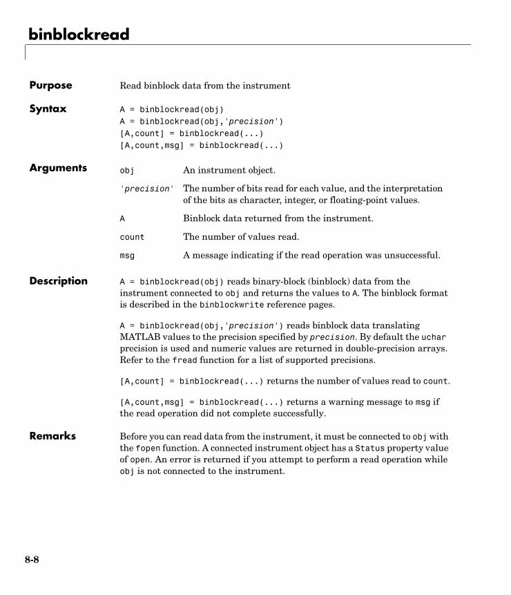
binblockread
8-8
8binblockreadPurpose Read binblock data from the instrument
Syntax A = binblockread(obj)A = binblockread(obj,'precision')[A,count] = binblockread(...)[A,count,msg] = binblockread(...)
Arguments
Description A = binblockread(obj) reads binary-block (binblock) data from the instrument connected to obj and returns the values to A. The binblock format is described in the binblockwrite reference pages.
A = binblockread(obj,'precision') reads binblock data translating MATLAB values to the precision specified by precision. By default the uchar precision is used and numeric values are returned in double-precision arrays. Refer to the fread function for a list of supported precisions.
[A,count] = binblockread(...) returns the number of values read to count.
[A,count,msg] = binblockread(...) returns a warning message to msg if the read operation did not complete successfully.
Remarks Before you can read data from the instrument, it must be connected to obj with the fopen function. A connected instrument object has a Status property value of open. An error is returned if you attempt to perform a read operation while obj is not connected to the instrument.
obj An instrument object.
'precision' The number of bits read for each value, and the interpretation of the bits as character, integer, or floating-point values.
A Binblock data returned from the instrument.
count The number of values read.
msg A message indicating if the read operation was unsuccessful.
binblockread
8-9
binblockread blocks the MATLAB command line until one of the following occurs:
• The data is completely read.
• The time specified by the Timeout property passes.
If msg is not included as an output argument and the read operation was not successful, then a warning message is returned to the command line.
The ValuesReceived property value is increased by the number of values read, each time binblockread is issued.
Example Create the GPIB object g associated with a National Instruments GPIB controller with board index 0, and a Tektronix TDS 210 oscilloscope with primary address 2.
g = gpib('ni',0,2);g.InputBufferSize = 3000;
Connect g to the instrument, and write string commands that configure the scope to transfer binary waveform data from memory location A.
fopen(g)fprintf(g,'DATA:DESTINATION REFA');fprintf(g,'DATA:ENCDG SRPbinary');fprintf(g,'DATA:WIDTH 1');fprintf(g,'DATA:START 1');
Write the CURVE? command, which prepares the scope to transfer data, and read the data using the binblock format.
fprintf(g,'CURVE?')data = binblockread(g);
See Also Functionsbinblockwrite, fopen, fread, instrhelp
PropertiesBytesAvailable, InputBufferSize, Status, ValuesReceived

binblockwrite
8-10
8binblockwritePurpose Write binblock data to the instrument
Syntax binblockwrite(obj,A)binblockwrite(obj,A,'precision')
Arguments
Description binblockwrite(obj,A) writes the data specified by A to the instrument connected to obj as a binary-block (binblock). The binblock format is defined as #<N><D><A> where
• N specifies the number of digits D that follow.
• D specifies the number of data bytes A that follow.
• A is the data written to the instrument.
For example, if A is given by [0 5 5 0 5 5 0], the binblock would be defined as [double('#') 1 7 0 5 5 0 5 5 0].
binblockwrite(obj,A,'precision') writes binblock data translating MATLAB values to the precision specified by precision. By default the uchar precision is used. Refer to the fwrite function for a list of supported precisions.
Remarks Before you can write data to the instrument, it must be connected to obj with the fopen function. A connected instrument object has a Status property value of open. An error is returned if you attempt to perform a write operation while obj is not connected to the instrument.
The ValuesSent property value is increased by the number of values written each time binblockwrite is issued.
An error occurs if the output buffer cannot hold all the data to be written. You can specify the size of the output buffer with the OutputBufferSize property.
obj An instrument object.
A The data to be written using the binblock format.
'precision' The number of bits written for each value, and the interpretation of the bits as character, integer, or floating-point values.
binblockwrite
8-11
Example Create the GPIB object g associated with a National Instruments GPIB controller with board index 0, and a Tektronix TDS 210 oscilloscope with primary address 2.
g = gpib('ni',0,2);g.OutputBufferSize = 3000;
Connect g to the instrument, and write string commands that configure the scope to transfer binary waveform data to memory location A.
fopen(g)fprintf(g,'DATA:DESTINATION REFA');fprintf(g,'DATA:ENCDG SRPbinary');fprintf(g,'DATA:WIDTH 1');fprintf(g,'DATA:START 1');
Create the waveform data.
t = linspace(0,25,2500);data = round(sin(t)*90 + 127);
Write the binblock data to the scope.
cmd = double('CURVE #42500');binblockwrite(g,[cmd data])
See Also Functionsbinblockread, fopen, fwrite, instrhelp
PropertiesOutputBufferSize, OutputEmptyFcn, Status, Timeout, TransferStatus, ValuesSent

clear
8-12
8clearPurpose Remove instrument objects from the MATLAB workspace
Syntax clear obj
Arguments
Description clear obj removes obj from the MATLAB workspace.
Remarks If obj is connected to the instrument and it is cleared from the workspace, then obj remains connected to the instrument. You can restore obj to the workspace with the instrfind function. An object connected to the instrument has a Status property value of open.
To disconnect obj from the instrument, use the fclose function. To remove obj from memory, use the delete function. You should remove invalid instrument objects from the workspace with clear.
Example This example creates the GPIB object g, copies g to a new variable gcopy, and clears g from the MATLAB workspace. g is then restored to the workspace with instrfind and is shown to be identical to gcopy.
g = gpib('ni',0,1);gcopy = g;clear gg = instrfind;isequal(gcopy,g)ans = 1
See Also Functionsdelete, fclose, instrfind, instrhelp, isvalid
PropertiesStatus
obj An instrument object or an array of instrument objects.
clrdevice
8-13
8clrdevicePurpose Clear instrument buffer
Syntax clrdevice(obj)
Arguments
Description clrdevice(obj) clears the hardware buffer of the instrument connected to obj.
Remarks Before you can clear the hardware buffer, the instrument must be connected to obj with the fopen function. A connected object has a Status property value of open. If you issue clrdevice when obj is disconnected from the instrument, then an error is returned.
You can clear the software input buffer using the flushinput function. You can clear the software output buffer using the flushoutput function.
See Also Functionsflushinput, flushoutput, fopen
PropertiesStatus
obj A GPIB, VISA-GPIB, VISA-VXI, or VISA-GPIB-VXI object.
delete
8-14
8deletePurpose Remove instrument objects from memory
Syntax delete(obj)
Arguments
Description delete(obj) removes obj from memory.
Remarks When you delete obj, it becomes an invalid object. Because you cannot connect an invalid object to the instrument, you should remove it from the workspace with the clear command. If multiple references to obj exist in the workspace, then deleting one reference invalidates the remaining references.
If obj is connected to the instrument, it has a Status property value of open. If you issue delete while obj is connected, then the connection is automatically broken. You can also disconnect obj from the instrument with the fclose function.
Example This example creates the GPIB object g, connects g to the instrument, writes and reads text data, disconnects g, removes g from memory using delete, and then removes g from the workspace using clear.
g = gpib('ni',0,1);fopen(g)fprintf(g,'*IDN?')idn = fscanf(g);fclose(g)delete(g)clear g
See Also Functionsclear, fclose, instrhelp, isvalid, stopasync
PropertiesStatus
obj An instrument object or an array of instrument objects.
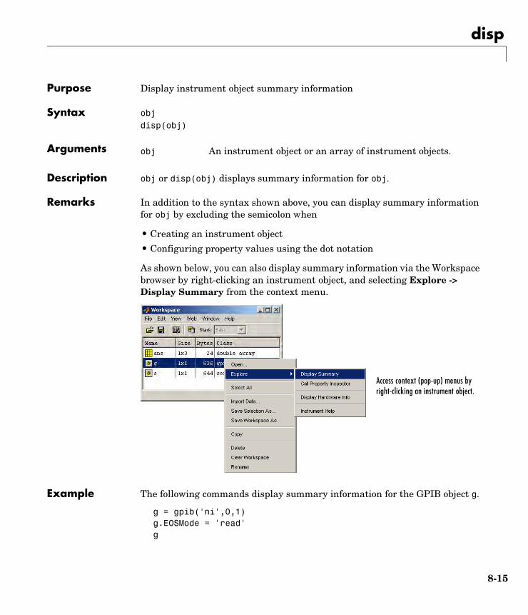
disp
8-15
8dispPurpose Display instrument object summary information
Syntax objdisp(obj)
Arguments
Description obj or disp(obj) displays summary information for obj.
Remarks In addition to the syntax shown above, you can display summary information for obj by excluding the semicolon when
• Creating an instrument object
• Configuring property values using the dot notation
As shown below, you can also display summary information via the Workspace browser by right-clicking an instrument object, and selecting Explore -> Display Summary from the context menu.
Example The following commands display summary information for the GPIB object g.
g = gpib('ni',0,1)g.EOSMode = 'read'g
obj An instrument object or an array of instrument objects.
Access context (pop-up) menus by right-clicking an instrument object.
echotcpip
8-16
8echotcpipPurpose Start or stop a TCP/IP echo server
Syntax echotcpip('state',port)echotcpip('state')
Arguments
Description echotcpip('state',port) starts a TCP/IP server with port number specified by port. state can only be on.
echotcpip('state') stops the echo server. state can only be off.
Example Start the echo server and create a TCP/IP object.
echotcpip('on',4000)t = tcpip('localhost',4000);
Connect the TCP/IP object to the host.
fopen(t)
Write to the host and read from the host.
fprintf(t,'echo this string.')data = fscanf(t);
Stop the echo server and disconnect the TCP/IP object from the host.
echotcpip('off')fclose(t)
See Also Functionsechoudp, tcpip, udp
'state' Turn the server on or off.
port Port number of the server.
echoudp
8-17
8echoudpPurpose Start or stop a UDP echo server
Syntax echoudp('state',port)echoudp('state')
Arguments
Description echoudp('state',port) starts a UDP server with port number specified by port. state can only be on.
echoudp('state') stops the echo server. state can only be off.
Example Start the echo server and create a UDP object.
echoudp('on',4012)u = udp('127.0.0.1',4012);
Connect the UDP object to the host.
fopen(u)
Write to the host and read from the host.
fwrite(u,65:74)A = fread(u,10);
Stop the echo server and disconnect the UDP object from the host.
echoudp('off')fclose(u)
See Also Functionsechotcpip, tcpip, udp
'state' Turn the server on or off.
port Port number of the server.
fclose
8-18
8fclosePurpose Disconnect an instrument object from the instrument
Syntax fclose(obj)
Arguments
Description fclose(obj) disconnects obj from the instrument.
Remarks If obj was successfully disconnected, then the Status property is configured to closed and the RecordStatus property is configured to off. You can reconnect obj to the instrument using the fopen function.
An error is returned if you issue fclose while data is being written asynchronously. In this case, you should abort the write operation with the stopasync function, or wait for the write operation to complete.
Example This example creates the GPIB object g, connects g to the instrument, writes and reads text data, and then disconnects g from the instrument using fclose.
g = gpib('ni',0,1);fopen(g)fprintf(g,'*IDN?')idn = fscanf(g);fclose(g)
At this point, you can once again connect an instrument object to the instrument. If you no longer need g, you should remove it from memory with the delete function, and remove it from the workspace with the clear command.
See Also Functionsclear, delete, fopen, instrhelp, record, stopasync
PropertiesRecordStatus, Status
obj An instrument object or an array of instrument objects.
fgetl
8-19
8fgetlPurpose Read one line of text from the instrument and discard the terminator
Syntax tline = fgetl(obj)[tline,count] = fgetl(obj)[tline,count,msg] = fgetl(obj)
Arguments
Description tline = fgetl(obj) reads one line of text from the instrument connected to obj, and returns the data to tline. The returned data does not include the terminator with the text line. To include the terminator, use fgets.
[tline,count] = fgetl(obj) returns the number of values read to count.
[tline,count,msg] = fgetl(obj) returns a warning message to msg if the read operation was unsuccessful.
Remarks Before you can read text from the instrument, it must be connected to obj with the fopen function. A connected instrument object has a Status property value of open. An error is returned if you attempt to perform a read operation while obj is not connected to the instrument.
If msg is not included as an output argument and the read operation was not successful, then a warning message is returned to the command line.
The ValuesReceived property value is increased by the number of values read — including the terminator — each time fgetl is issued.
obj An instrument object.
tline The text read from the instrument, excluding the terminator.
count The number of values read, including the terminator.
msg A message indicating if the read operation was unsuccessful.
fgetl
8-20
Rules for Completing a Read Operation with fgetlA read operation with fgetl blocks access to the MATLAB command line until
• The terminator is read. For serial port, TCP/IP, UDP, and VISA-serial objects, the terminator is given by the Terminator property. Note that for UDP objects, DatagramTerminateMode must be off.
For all other instrument objects except VISA-RSIB, the terminator is given by the EOSCharCode property.
• The EOI line is asserted (GPIB and VXI instruments only).
• A datagram has been received (UDP objects only if DatagramTerminateMode is on).
• The time specified by the Timeout property passes.
• The input buffer is filled.
More About the GPIB and VXI TerminatorThe EOSCharCode property value is recognized only when the EOSMode property is configured to read or read&write. For example, if EOSMode is configured to read and EOSCharCode is configured to LF, then one of the ways that the read operation terminates is when the line feed character is received.
If EOSMode is none or write, then there is no terminator defined for read operations. In this case, fgetl will complete execution and return control to the command line when another criterion, such as a timeout, is met.
Example Create the GPIB object g, connect g to a Tektronix TDS 210 oscilloscope, configure g to complete read operations when the End-Of-String character is read, and write the *IDN? command with the fprintf function. *IDN? instructs the scope to return identification information.
g = gpib('ni',0,1);fopen(g)g.EOSMode = 'read';fprintf(g,'*IDN?')

fgetl
8-21
Asynchronously read the identification information from the instrument.
readasync(g)g.BytesAvailableans = 56
Use fgetl to transfer the data from the input buffer to the MATLAB workspace, and discard the terminator.
idn = fgetl(g)idn =TEKTRONIX,TDS 210,0,CF:91.1CT FV:v1.16 TDS2CM:CMV:v1.04
length(idn)ans = 55
Disconnect g from the scope, and remove g from memory and the workspace.
fclose(g)delete(g)clear g
See Also Functionsfgets, fopen, instrhelp
PropertiesBytesAvailable, EOSCharCode, EOSMode, InputBufferSize, Status, Terminator, Timeout, ValuesReceived
fgets
8-22
8fgetsPurpose Read one line of text from the instrument and include the terminator
Syntax tline = fgets(obj)[tline,count] = fgets(obj)
[tline,count,msg] = fgets(obj)
Arguments
Description tline = fgets(obj) reads one line of text from the instrument connected to obj, and returns the data to tline. The returned data includes the terminator with the text line. To exclude the terminator, use fgetl.
[tline,count] = fgets(obj) returns the number of values read to count.
[tline,count,msg] = fgets(obj) returns a warning message to msg if the read operation was unsuccessful.
Remarks Before you can read text from the instrument, it must be connected to obj with the fopen function. A connected instrument object has a Status property value of open. An error is returned if you attempt to perform a read operation while obj is not connected to the instrument.
If msg is not included as an output argument and the read operation was not successful, then a warning message is returned to the command line.
The ValuesReceived property value is increased by the number of values read — including the terminator — each time fgets is issued.
obj An instrument object.
tline The text read from the instrument, including the terminator.
count The number of values read.
msg A message indicating that the read operation did not complete successfully.
fgets
8-23
Rules for Completing a Read Operation with fgetsA read operation with fgets blocks access to the MATLAB command line until
• The terminator is read. For serial port, TCP/IP, UDP, and VISA-serial objects, the terminator is given by the Terminator property. Note that for UDP objects, DatagramTerminateMode must be off.
For all other instrument objects except VISA-RSIB, the terminator is given by the EOSCharCode property.
• The EOI line is asserted (GPIB and VXI instruments only).
• A datagram has been received (UDP objects only if DatagramTerminateMode is on).
• The time specified by the Timeout property passes.
• The input buffer is filled.
More About the GPIB and VXI TerminatorThe EOSCharCode property value is recognized only when the EOSMode property is configured to read or read&write. For example, if EOSMode is configured to read and EOSCharCode is configured to LF, then one of the ways that the read operation terminates is when the line feed character is received.
If EOSMode is none or write, then there is no terminator defined for read operations. In this case, fgets will complete execution and return control to the command line when another criterion, such as a timeout, is met.
Example Create the GPIB object g, connect g to a Tektronix TDS 210 oscilloscope, configure g to complete read operations when the End-Of-String character is read, and write the *IDN? command with the fprintf function. *IDN? instructs the scope to return identification information.
g = gpib('ni',0,1);fopen(g)g.EOSMode = 'read';fprintf(g,'*IDN?')

fgets
8-24
Asynchronously read the identification information from the instrument.
readasync(g)g.BytesAvailableans = 56
Use fgets to transfer the data from the input buffer to the MATLAB workspace, and include the terminator.
idn = fgets(g)idn =TEKTRONIX,TDS 210,0,CF:91.1CT FV:v1.16 TDS2CM:CMV:v1.04length(idn)ans = 56
Disconnect g from the scope, and remove g from memory and the workspace.
fclose(g)delete(g)clear g
See Also Functionsfgetl, fopen, instrhelp, query
PropertiesBytesAvailable, EOSCharCode, EOSMode, InputBufferSize, Status, Terminator, Timeout, ValuesReceived

flushinput
8-25
8flushinputPurpose Remove data from the input buffer
Syntax flushinput(obj)
Arguments
Description flushinput(obj) removes data from the input buffer associated with obj.
Remarks After the input buffer is flushed, the BytesAvailable property is automatically configured to 0.
If flushinput is called during an asynchronous (nonblocking) read operation, the data currently stored in the input buffer is flushed and the read operation continues. You can read data asynchronously from the instrument using the readasync function.
The input buffer is automatically flushed when you connect an object to the instrument with the fopen function.
You can clear the output buffer with the flushoutput function. You can clear the hardware buffer for GPIB and VXI instruments with the clrdevice function.
See Also Functionsclrdevice, flushoutput, fopen, readasync
PropertiesBytesAvailable
obj An instrument object or an array of instrument objects.
flushoutput
8-26
8flushoutputPurpose Remove data from the output buffer
Syntax flushoutput(obj)
Arguments
Description flushoutput(obj) removes data from the output buffer associated with obj.
Remarks After the output buffer is flushed, the BytesToOutput property is automatically configured to 0.
If flushoutput is called during an asynchronous (nonblocking) write operation, the data currently stored in the output buffer is flushed and the write operation is aborted. Additionally, the M-file callback function specified for the OutputEmptyFcn property is executed. You can write data asynchronously to the instrument using the fprintf or fwrite functions.
The output buffer is automatically flushed when you connect an object to the instrument with the fopen function.
You can clear the input buffer with the flushinput function. You can clear the hardware buffer for GPIB and VXI instruments with the clrdevice function.
See Also Functionsclrdevice, flushinput, fopen, fprintf, fwrite
PropertiesBytesToOutput, OutputEmptyFcn
obj An instrument object or an array of instrument objects.
fopen
8-27
8fopenPurpose Connect an instrument object to the instrument
Syntax fopen(obj)
Arguments
Description fopen(obj) connects obj to the instrument.
Remarks Before you can perform a read or write operation, obj must be connected to the instrument with the fopen function. When obj is connected to the instrument
• Data remaining in the input buffer or the output buffer is flushed.
• The Status property is set to open.
• The BytesAvailable, ValuesReceived, ValuesSent, and BytesToOutput properties are set to 0.
An error is returned if you attempt to perform a read or write operation while obj is not connected to the instrument. You can connect only one instrument object to the same instrument. For example, you can connect only one serial port object to an instrument associated with the COM1 port. Similarly, you can connect only one GPIB object to an instrument with a given board index, primary address, and secondary address.
Some properties are read-only while the instrument object is open (connected), and must be configured before using fopen. Examples include InputBufferSize and OutputBufferSize. Refer to the property reference pages or use the propinfo function to determine which properties have this constraint.
The values for some properties are verified only after obj is connected to the instrument. If any of these properties are incorrectly configured, then an error is returned when fopen is issued and obj is not connected to the instrument. Properties of this type include BaudRate and SecondaryAddress, and are associated with instrument settings.
obj An instrument object or an array of instrument objects.
fopen
8-28
Example This example creates the GPIB object g, connects g to the instrument using fopen, writes and reads text data, and then disconnects g from the instrument.
g = gpib('ni',0,1);fopen(g)fprintf(g,'*IDN?')idn = fscanf(g);fclose(g)
See Also Functionsfclose, instrhelp, propinfo
PropertiesBytesAvailable, BytesToOutput, Status, ValuesReceived, ValuesSent
fprintf
8-29
8fprintfPurpose Write text to the instrument
Syntax fprintf(obj,'cmd')fprintf(obj,'format','cmd')fprintf(obj,'cmd','mode')fprintf(obj,'format','cmd','mode')
Arguments
Description fprintf(obj,'cmd') writes the string cmd to the instrument connected to obj. The default format is %s\n. The write operation is synchronous and blocks the command line until execution is complete.
fprintf(obj,'format','cmd') writes the string using the format specified by format.
format is a C language conversion specification. Conversion specifications involve the % character and the conversion characters d, i, o, u, x, X, f, e, E, g, G, c, and s. Refer to the sprintf file I/O format specifications or a C manual for more information.
fprintf(obj,'cmd','mode') writes the string with command-line access specified by mode. If mode is sync, cmd is written synchronously and the command line is blocked. If mode is async, cmd is written asynchronously and the command line is not blocked. If mode is not specified, the write operation is synchronous.
fprintf(obj,'format','cmd','mode') writes the string using the specified format. If mode is sync, cmd is written synchronously. If mode is async, cmd is written asynchronously.
obj An instrument object.
'cmd' The string written to the instrument.
'format' C language conversion specification.
'mode' Specifies whether data is written synchronously or asynchronously.
fprintf
8-30
Remarks Before you can write text to the instrument, it must be connected to obj with the fopen function. A connected instrument object has a Status property value of open. An error is returned if you attempt to perform a write operation while obj is not connected to the instrument.
The ValuesSent property value is increased by the number of values written each time fprintf is issued.
An error occurs if the output buffer cannot hold all the data to be written. You can specify the size of the output buffer with the OutputBufferSize property.
Synchronous Versus Asynchronous Write OperationsBy default, text is written to the instrument synchronously and the command line is blocked until the operation completes. You can perform an asynchronous write by configuring the mode input argument to be async. For asynchronous writes,
• The BytesToOutput property value is continuously updated to reflect the number of bytes in the output buffer.
• The M-file callback function specified for the OutputEmptyFcn property is executed when the output buffer is empty.
You can determine whether an asynchronous write operation is in progress with the TransferStatus property.
Synchronous and asynchronous write operations are discussed in more detail in “Synchronous Versus Asynchronous Write Operations” on page 2-17.
Rules for Completing a Write Operation with fprintfA write operation using fprintf completes when
• The specified data is written.
• The time specified by the Timeout property passes.
Rules for Writing the TerminatorFor serial port, TCP/IP, UDP, and VISA-serial objects, all occurrences of \n in cmd are replaced with the Terminator property value. Therefore, when using the default format %s\n, all commands written to the instrument will end with this property value.
fprintf
8-31
For GPIB, VISA-GPIB, VISA-VXI, and VISA-GPIB-VXI objects, all occurrences of \n in cmd are replaced with the EOSCharCode property value if the EOSMode property is set to write or read&write. For example, if EOSMode is set to write and EOSCharCode is set to LF, then all occurrences of \n are replaced with a line feed character. Additionally, for GPIB objects, the End Or Identify (EOI) line is asserted when the terminator is written out.
Note The terminator required by your instrument will be described in its documentation.
Example Create the serial port object s, connect s to a Tektronix TDS 210 oscilloscope, and write the RS232? command with the fprintf function. RS232? instructs the scope to return serial port communications settings.
s = serial('COM1');fopen(s)fprintf(s,'RS232?')settings = fscanf(s)settings =9600;1;0;NONE;LF
Because the default format for fprintf is %s\n, the terminator specified by the Terminator property was automatically written. However, in some cases you might want to suppress writing the terminator. To do so, you must explicitly specify a format for the data that does not include the terminator, or configure the terminator to empty.
fprintf(s,'%s','RS232?')
See Also Functionsfopen, fwrite, instrhelp, query, sprintf
PropertiesBytesToOutput, EOSCharCode, EOSMode, OutputBufferSize, OutputEmptyFcn, Status, TransferStatus, ValuesSent
fread
8-32
8freadPurpose Read binary data from the instrument
Syntax A = fread(obj,size)A = fread(obj,size,'precision')[A,count] = fread(...)[A,count,msg] = fread(...)[A,count,msg,datagramaddress] = fread(obj,...)[A,count,msg,datagramaddress,datagramport] = fread(obj,...)
Arguments
Description A = fread(obj,size) reads binary data from the instrument connected to obj, and returns the data to A. The maximum number of values to read is specified by size. Valid options for size are
size cannot be inf, and an error is returned if the specified number of values cannot be stored in the input buffer. You specify the size, in bytes, of the input buffer with the InputBufferSize property. A value is defined as a byte multiplied by the precision (see below).
obj An instrument object.
size The number of values to read.
'precision' The number of bits read for each value, and the interpretation of the bits as character, integer, or floating-point values.
A Binary data returned from the instrument.
count The number of values read.
msg A message indicating if the read operation was unsuccessful.
datagramaddress The address of the datagram sender.
datagramport The port of the datagram sender.
n Read at most n values into a column vector.
[m,n] Read at most m–by–n values filling an m–by–n matrix in column order.
fread
8-33
If obj is a UDP object and DatagramTerminateMode is off, the size value is honored. If size is less than the length of the datagram, only size values are read. If size is greater than the length of the datagram, a warning is issued stating that a complete datagram was read before size values was reached.
A = fread(obj,size,'precision') reads binary data with precision specified by precision.
precision controls the number of bits read for each value and the interpretation of those bits as integer, floating-point, or character values. If precision is not specified, uchar (an 8-bit unsigned character) is used. By default, numeric values are returned in double-precision arrays. The supported values for precision are listed below in Remarks.
[A,count] = fread(...) returns the number of values read to count.
[A,count,msg] = fread(...) returns a warning message to msg if the read operation was unsuccessful.
[A,count,msg,datagramaddress] = fread(obj,...) returns the datagram address to datagramaddress if obj is a UDP object. If more than one datagram is read, datagramaddress is ' '.
[A,count,msg,datagramaddress,datagramport] = fread(obj,...) returns the datagram port to datagramport if obj is a UDP object. If more than one datagram is read, datagramport is [ ].
Remarks Before you can read data from the instrument, it must be connected to obj with the fopen function. A connected instrument object has a Status property value of open. An error is returned if you attempt to perform a read operation while obj is not connected to the instrument.
If msg is not included as an output argument and the read operation was not successful, then a warning message is returned to the command line.
The ValuesReceived property value is increased by the number of values read, each time fread is issued.
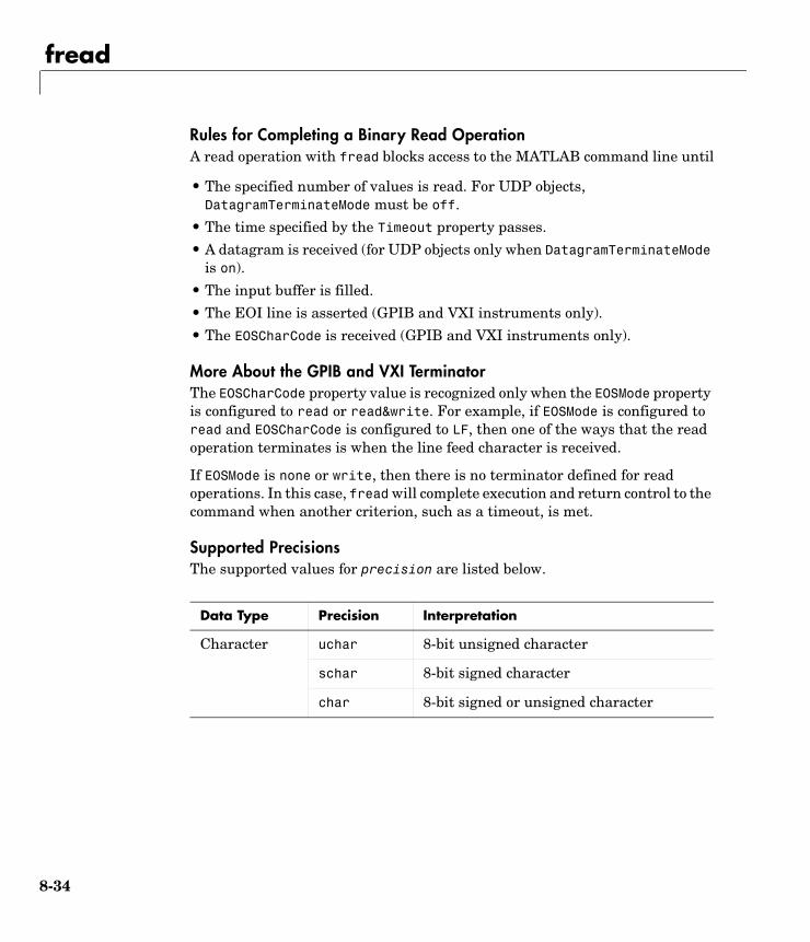
fread
8-34
Rules for Completing a Binary Read OperationA read operation with fread blocks access to the MATLAB command line until
• The specified number of values is read. For UDP objects, DatagramTerminateMode must be off.
• The time specified by the Timeout property passes.
• A datagram is received (for UDP objects only when DatagramTerminateMode is on).
• The input buffer is filled.
• The EOI line is asserted (GPIB and VXI instruments only).
• The EOSCharCode is received (GPIB and VXI instruments only).
More About the GPIB and VXI TerminatorThe EOSCharCode property value is recognized only when the EOSMode property is configured to read or read&write. For example, if EOSMode is configured to read and EOSCharCode is configured to LF, then one of the ways that the read operation terminates is when the line feed character is received.
If EOSMode is none or write, then there is no terminator defined for read operations. In this case, fread will complete execution and return control to the command when another criterion, such as a timeout, is met.
Supported PrecisionsThe supported values for precision are listed below.
Data Type Precision Interpretation
Character uchar 8-bit unsigned character
schar 8-bit signed character
char 8-bit signed or unsigned character
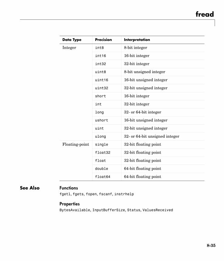
fread
8-35
See Also Functionsfgetl, fgets, fopen, fscanf, instrhelp
PropertiesBytesAvailable, InputBufferSize, Status, ValuesReceived
Integer int8 8-bit integer
int16 16-bit integer
int32 32-bit integer
uint8 8-bit unsigned integer
uint16 16-bit unsigned integer
uint32 32-bit unsigned integer
short 16-bit integer
int 32-bit integer
long 32- or 64-bit integer
ushort 16-bit unsigned integer
uint 32-bit unsigned integer
ulong 32- or 64-bit unsigned integer
Floating-point single 32-bit floating point
float32 32-bit floating point
float 32-bit floating point
double 64-bit floating point
float64 64-bit floating point
Data Type Precision Interpretation
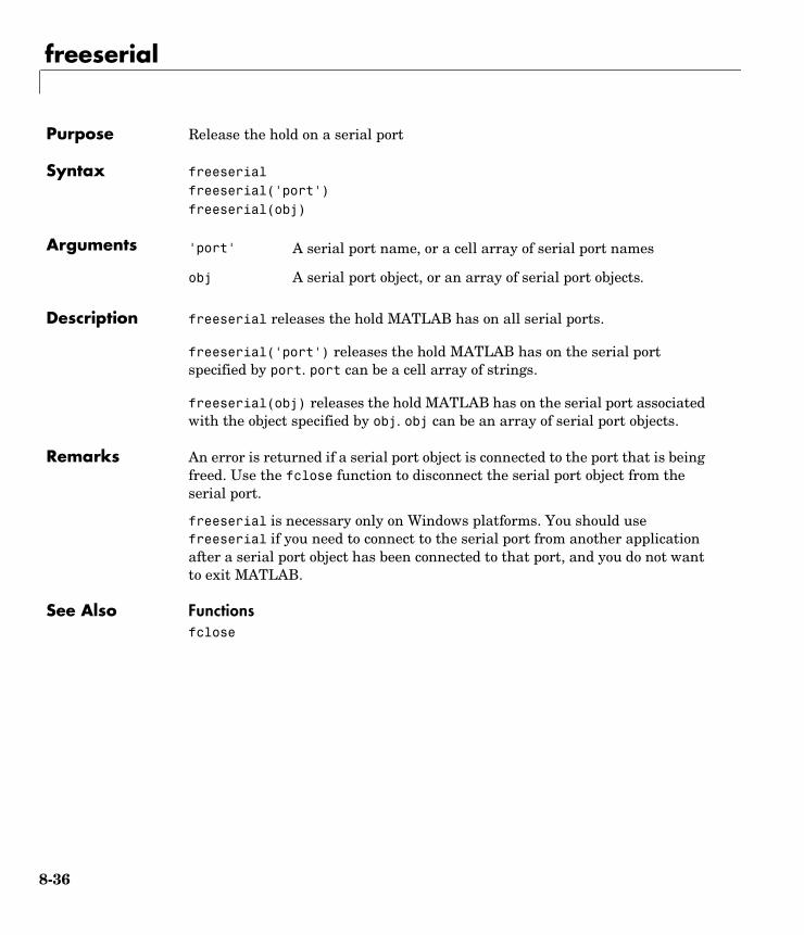
freeserial
8-36
8freeserialPurpose Release the hold on a serial port
Syntax freeserialfreeserial('port')freeserial(obj)
Arguments
Description freeserial releases the hold MATLAB has on all serial ports.
freeserial('port') releases the hold MATLAB has on the serial port specified by port. port can be a cell array of strings.
freeserial(obj) releases the hold MATLAB has on the serial port associated with the object specified by obj. obj can be an array of serial port objects.
Remarks An error is returned if a serial port object is connected to the port that is being freed. Use the fclose function to disconnect the serial port object from the serial port.
freeserial is necessary only on Windows platforms. You should use freeserial if you need to connect to the serial port from another application after a serial port object has been connected to that port, and you do not want to exit MATLAB.
See Also Functionsfclose
'port' A serial port name, or a cell array of serial port names
obj A serial port object, or an array of serial port objects.
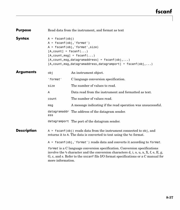
fscanf
8-37
8fscanfPurpose Read data from the instrument, and format as text
Syntax A = fscanf(obj)A = fscanf(obj,'format')A = fscanf(obj,'format',size)[A,count] = fscanf(...)[A,count,msg] = fscanf(...)[A,count,msg,datagramaddress] = fscanf(obj,...)[A,count,msg,datagramaddress,datagramport] = fscanf(obj,...)
Arguments
Description A = fscanf(obj) reads data from the instrument connected to obj, and returns it to A. The data is converted to text using the %c format.
A = fscanf(obj,'format') reads data and converts it according to format.
format is a C language conversion specification. Conversion specifications involve the % character and the conversion characters d, i, o, u, x, X, f, e, E, g, G, c, and s. Refer to the sscanf file I/O format specifications or a C manual for more information.
obj An instrument object.
'format' C language conversion specification.
size The number of values to read.
A Data read from the instrument and formatted as text.
count The number of values read.
msg A message indicating if the read operation was unsuccessful.
datagramaddress
The address of the datagram sender.
datagramport The port of the datagram sender.
fscanf
8-38
A = fscanf(obj,'format',size) reads the number of values specified by size. Valid options for size are
size cannot be inf, and an error is returned if the specified number of values cannot be stored in the input buffer. If size is not of the form [m,n], and a character conversion is specified, then A is returned as a row vector. You specify the size, in bytes, of the input buffer with the InputBufferSize property. An ASCII value is one byte.
If obj is a UDP object and DatagramTerminateMode is off, the size value is honored. If size is less than the length of the datagram, only size values are read. If size is greater than the length of the datagram, a warning is issued stating that a complete datagram was read before size values was reached.
[A,count] = fscanf(...) returns the number of values read to count.
[A,count,msg] = fscanf(...) returns a warning message to msg if the read operation did not complete successfully.
[A,count,msg,datagramaddress] = fscanf(obj,...) returns the datagram address to datagramaddress if obj is a UDP object. If more than one datagram is read, datagramaddress is ' '.
[A,count,msg,datagramaddress,datagramport] = fscanf(obj,...)returns the datagram port to datagramport if obj is a UDP object. If more than one datagram is read, datagramport is [ ].
Remarks Before you can read data from the instrument, it must be connected to obj with the fopen function. A connected instrument object has a Status property value of open. An error is returned if you attempt to perform a read operation while obj is not connected to the instrument.
If msg is not included as an output argument and the read operation was not successful, then a warning message is returned to the command line.
n Read at most n values into a column vector.
[m,n] Read at most m–by–n values filling an m–by–n matrix in column order.
fscanf
8-39
The ValuesReceived property value is increased by the number of values read — including the terminator — each time fscanf is issued.
Rules for Completing a Read Operation with fscanfA read operation with fscanf blocks access to the MATLAB command line until
• The terminator is read. For serial port, TCP/IP, UDP, and VISA-serial objects, the terminator is given by the Terminator property. If Terminator is empty, fscanf will complete execution and return control when another criterion is met. For UDP objects, DatagramTerminateMode must be off.
For all other instrument objects, the terminator is given by the EOSCharCode property.
• The time specified by the Timeout property passes.
• The number of values specified by size is read. For UDP objects, DatagramTerminateMode must be off.
• A datagram is received (for UDP objects only when DatagramTerminateMode is on).
• The input buffer is filled.
• The EOI line is asserted (GPIB and VXI instruments only).
More About the GPIB and VXI TerminatorThe EOSCharCode property value is recognized only when the EOSMode property is configured to read or read&write. For example, if EOSMode is configured to read and EOSCharCode is configured to LF, then one of the ways that the read operation terminates is when the line feed character is received.
If EOSMode is none or write, then there is no terminator defined for read operations. In this case, fscanf will complete execution and return control to the command when another criterion, such as a timeout, is met.
Example Create the serial port object s and connect s to a Tektronix TDS 210 oscilloscope, which is displaying a sine wave.
s = serial('COM1');fopen(s)
fscanf
8-40
Use the fprintf function to configure the scope to measure the peak-to-peak voltage of the sine wave, return the measurement type, and return the peak-to-peak voltage.
fprintf(s,'MEASUREMENT:IMMED:TYPE PK2PK')fprintf(s,'MEASUREMENT:IMMED:TYPE?')fprintf(s,'MEASUREMENT:IMMED:VAL?')
Because the default value for the ReadAsyncMode property is continuous, data associated with the two query commands is automatically returned to the input buffer.
s.BytesAvailableans = 13
Use fscanf to read the measurement type. The operation will complete when the first terminator is read.
meas = fscanf(s)meas =PK2PK
Use fscanf to read the peak-to-peak voltage as a floating-point number, and exclude the terminator.
pk2pk = fscanf(s,'%e',6)pk2pk = 2.0200
Disconnect s from the scope, and remove s from memory and the workspace.
fclose(s)delete(s)clear s
See Also Functionsfgetl, fgets, fopen, fread, instrhelp, scanstr, sscanf
PropertiesBytesAvailable, BytesAvailableFcn, EOSCharCode, EOSMode, InputBufferSize, Status, Terminator, Timeout, TransferStatus
fwrite
8-41
8fwritePurpose Write binary data to the instrument
Syntax fwrite(obj,A)fwrite(obj,A,'precision')fwrite(obj,A, mode')fwrite(obj,A,'precision', mode')
Arguments
Description fwrite(obj,A) writes the binary data A to the instrument connected to obj.
fwrite(obj,A,'precision') writes binary data with precision specified by precision.
precision controls the number of bits written for each value and the interpretation of those bits as integer, floating-point, or character values. If precision is not specified, uchar (an 8-bit unsigned character) is used. The supported values for precision are listed below in Remarks.
fwrite(obj,A,'mode') writes binary data with command line access specified by mode. If mode is sync, A is written synchronously and the command line is blocked. If mode is async, A is written asynchronously and the command line is not blocked. If mode is not specified, the write operation is synchronous.
fwrite(obj,A,'precision','mode') writes binary data with precision specified by precision and command line access specified by mode.
Remarks Before you can write data to the instrument, it must be connected to obj with the fopen function. A connected instrument object has a Status property value of open. An error is returned if you attempt to perform a write operation while obj is not connected to the instrument.
obj An instrument object.
A The binary data written to the instrument.
'precision' The number of bits written for each value, and the interpretation of the bits as character, integer, or floating-point values.
'mode' Specifies whether data is written synchronously or asynchronously.
fwrite
8-42
The ValuesSent property value is increased by the number of values written each time fwrite is issued.
An error occurs if the output buffer cannot hold all the data to be written. You can specify the size of the output buffer with the OutputBufferSize property.
Synchronous Versus Asynchronous Write OperationsBy default, data is written to the instrument synchronously and the command line is blocked until the operation completes. You can perform an asynchronous write by configuring the mode input argument to be async. For asynchronous writes,
• The BytesToOutput property value is continuously updated to reflect the number of bytes in the output buffer.
• The M-file callback function specified for the OutputEmptyFcn property is executed when the output buffer is empty.
You can determine whether an asynchronous write operation is in progress with the TransferStatus property.
Synchronous and asynchronous write operations are discussed in more detail in “Synchronous Versus Asynchronous Write Operations” on page 2-17.
Rules for Completing a Write Operation with fwriteA binary write operation using fwrite completes when
• The specified data is written.
• The time specified by the Timeout property passes.
Note The Terminator and EOSCharCode properties are not used with binary write operations.
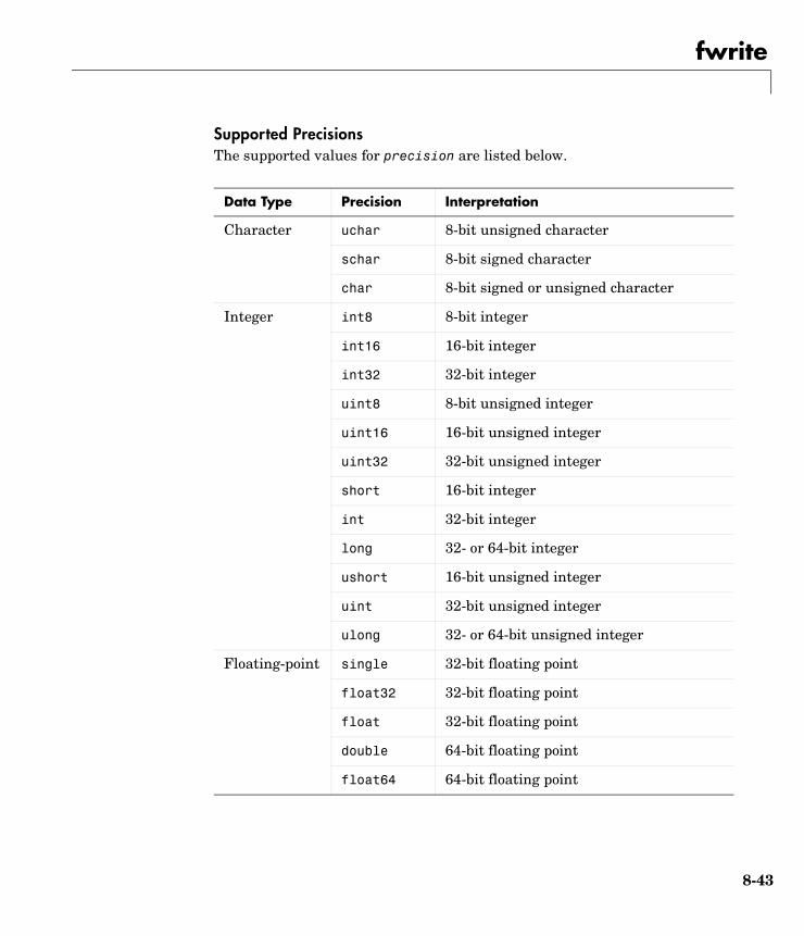
fwrite
8-43
Supported PrecisionsThe supported values for precision are listed below.
Data Type Precision Interpretation
Character uchar 8-bit unsigned character
schar 8-bit signed character
char 8-bit signed or unsigned character
Integer int8 8-bit integer
int16 16-bit integer
int32 32-bit integer
uint8 8-bit unsigned integer
uint16 16-bit unsigned integer
uint32 32-bit unsigned integer
short 16-bit integer
int 32-bit integer
long 32- or 64-bit integer
ushort 16-bit unsigned integer
uint 32-bit unsigned integer
ulong 32- or 64-bit unsigned integer
Floating-point single 32-bit floating point
float32 32-bit floating point
float 32-bit floating point
double 64-bit floating point
float64 64-bit floating point

fwrite
8-44
See Also Functionsfopen, fprintf, instrhelp
PropertiesOutputBufferSize, OutputEmptyFcn, Status, Timeout, TransferStatus, ValuesSent
get
8-45
8getPurpose Return instrument object properties
Syntax get(obj)out = get(obj)out = get(obj,'PropertyName')
Arguments
Description get(obj) returns all property names and their current values to the command line for obj. The properties are divided into two sections. The base properties are listed first and the object-specific properties are listed second.
out = get(obj) returns the structure out where each field name is the name of a property of obj, and each field contains the value of that property.
out = get(obj,'PropertyName') returns the value out of the property specified by PropertyName for obj. If PropertyName is replaced by a 1-by-n or n-by-1 cell array of strings containing property names, then get returns a 1-by-n cell array of values to out. If obj is an array of instrument objects, then out will be a m-by-n cell array of property values where m is equal to the length of obj and n is equal to the number of properties specified.
Remarks When you specify a property name, you can do so without regard to case, and you can make use of property name completion. For example, if g is a GPIB object, then these commands are all valid.
out = get(g,'EOSMode');out = get(g,'eosmode');out = get(g,'EOSM');
obj An instrument object or an array of instrument objects.
'PropertyName' A property name or a cell array of property names.
out A single property value, a structure of property values, or a cell array of property values.
get
8-46
Example This example illustrates some of the ways you can use get to return property values for the GPIB object g.
g = gpib('ni',0,1);out1 = get(g);out2 = get(g,{'PrimaryAddress','EOSCharCode'});get(g,'EOIMode')ans =on
See Also Functionsinstrhelp, propinfo, set
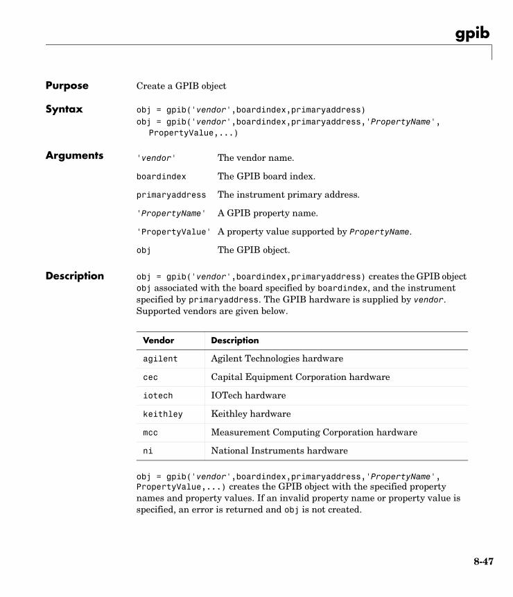
gpib
8-47
8gpibPurpose Create a GPIB object
Syntax obj = gpib('vendor',boardindex,primaryaddress)obj = gpib('vendor',boardindex,primaryaddress,'PropertyName',
PropertyValue,...)
Arguments
Description obj = gpib('vendor',boardindex,primaryaddress) creates the GPIB object obj associated with the board specified by boardindex, and the instrument specified by primaryaddress. The GPIB hardware is supplied by vendor. Supported vendors are given below.
obj = gpib('vendor',boardindex,primaryaddress,'PropertyName', PropertyValue,...) creates the GPIB object with the specified property names and property values. If an invalid property name or property value is specified, an error is returned and obj is not created.
'vendor' The vendor name.
boardindex The GPIB board index.
primaryaddress The instrument primary address.
'PropertyName' A GPIB property name.
'PropertyValue' A property value supported by PropertyName.
obj The GPIB object.
Vendor Description
agilent Agilent Technologies hardware
cec Capital Equipment Corporation hardware
iotech IOTech hardware
keithley Keithley hardware
mcc Measurement Computing Corporation hardware
ni National Instruments hardware
gpib
8-48
Remarks At any time, you can use the instrhelp function to view a complete listing of properties and functions associated with GPIB objects.
instrhelp gpib
When you create a GPIB object, these property value are automatically configured:
• The Type property is given by gpib.
• The Name property is given by concatenating GPIB with the board index and the primary address specified in the gpib function. If the secondary address is specified, then this value is also used in Name.
• The BoardIndex and PrimaryAddress property values are given by the values supplied to gpib.
You can specify the property names and property values using any format supported by the set function. For example, you can use property name/property value cell array pairs. Additionally, you can specify property names without regard to case, and you can make use of property name completion. For example, these commands are all valid:
g = gpib(ni,0,1,'SecondaryAddress',96)g = gpib(ni,0,1,'secondaryaddress',96)g = gpib(ni,0,1,'SECOND',96)
Before you can communicate with the instrument, it must be connected to obj with the fopen function. A connected instrument object has a Status property value of open. An error is returned if you attempt to perform a read or write operation while obj is not connected to the instrument.
You cannot connect multiple GPIB objects to the same instrument. A GPIB instrument is uniquely identified by its board index, primary address, and secondary address.
Example This example creates the GPIB object g1 associated with a National Instruments board at index 0 with primary address 1, and then connects g1 to the instrument.
g1 = gpib('ni',0,1);fopen(g1)
gpib
8-49
The Type, Name, BoardIndex, and PrimaryAddress properties are automatically configured.
get(g1, {'Type','Name','BoardIndex','PrimaryAddress'})ans = 'gpib' 'GPIB0-1' [0] [1]
To specify the secondary address during object creation:
g2 = gpib('ni',0,1,'SecondaryAddress',96);
See Also Functionsfopen, instrhelp, instrhwinfo
PropertiesBoardIndex, Name, PrimaryAddress, SecondaryAddress, Status, Type
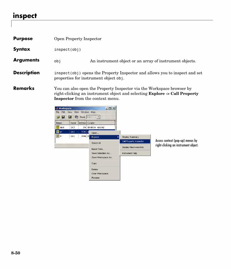
inspect
8-50
8inspectPurpose Open Property Inspector
Syntax inspect(obj)
Arguments
Description inspect(obj) opens the Property Inspector and allows you to inspect and set properties for instrument object obj.
Remarks You can also open the Property Inspector via the Workspace browser by right-clicking an instrument object and selecting Explore -> Call Property Inspector from the context menu.
obj An instrument object or an array of instrument objects.
Access context (pop-up) menus by right-clicking an instrument object.
instrcallback
8-51
8instrcallbackPurpose Display event information when an event occurs
Syntax instrcallback(obj,event)
Arguments
Description instrcallback(obj,event) displays a message that contains the event type, the time the event occurred, and the name of the instrument object that caused the event to occur.
For error events, the error message is also displayed. For pin status events, the pin that changed value and its value are also displayed. For trigger events, the trigger line is also displayed. For datagram received events, the number of bytes received and the datagram address and port are also displayed.
Remarks You should use instrcallback as a template from which you create callback functions that suit your specific application needs.
Example The following example creates the serial port objects s, and configures s to execute instrcallback when an output-empty event occurs. The event occurs after the *IDN? command is written to the instrument.
s = serial('COM1');set(s,'OutputEmptyFcn',@instrcallback)fopen(s)fprintf(s,'*IDN?','async')
The resulting display from instrcallback is shown below.
OutputEmpty event occurred at 08:37:49 for the object: Serial-COM1
Read the identification information from the input buffer and end the serial port session.
idn = fscanf(s);fclose(s)delete(s)clear s
obj An instrument object.
event The event that caused the callback to execute.

instrcomm
8-52
8instrcommPurpose Graphical tool for communicating with an instrument using text data
Syntax instrcomm(obj)
instrcomm
Arguments
Description instrcomm(obj) launches the Instrument Control ASCII Communication Tool for the instrument object obj. instrcomm provides you with these features and capabilities:
• Connect obj to the instrument, and disconnect obj from the instrument.
• Initiate and terminate recording.
• Perform synchronous read, write, and query operations for text commands. A history of transferred data is also provided.
• Flush the input buffer.
• Monitor the values sent and values received.
instrcomm launches the Instrument Control Configuration Tool, instrcreate. After you create an instrument object, it is automatically passed to the Instrument Control ASCII Communication Tool.
Example This example uses instrcomm to communicate with a Tektronix TDS 210 oscilloscope, and saves the data to a record file. The read and write operations are taken from “Example: Writing and Reading Text Data” on page 3-22.
First, create the GPIB object g at the command line. Note that you can also create this object using instrcreate.
g = gpib('ni',0,1);
Launch the Instrument Control ASCII Communication Tool for g.
instrcomm(g)
obj An instrument object

instrcomm
8-53
The initial instrcomm window is shown below. Note that the object name is displayed in the figure title.
The communication session follows these steps:
1 In the Communication State panel, select the Connect button to connect g to the instrument, and select the Start button to initiate recording.
2 Input the instrument commands one at a time, and select the Write, Read, or Query button as needed for each command.
You can specify the command and data format using the Format parameters, and you can clear the commands and data from the interface tool using the Clear Commands and Clear Data buttons, respectively.

instrcomm
8-54
The complete communication session is shown below. The most recent command written to the instrument is at the top of the Command list, while the most recent command response read from the instrument is at the bottom of the Data list.
See Also Functionsinstrcreate
instrcreate
8-55
8instrcreatePurpose Graphical tool for creating and configuring an instrument object
Syntax instrcreateobj = instrcreate
Arguments
Description instrcreate launches the Instrument Control Configuration Tool. Using this tool, you can create and configure an instrument object. You can then save the instrument object to the MATLAB workspace, convert it to the equivalent M-code, or save it to a MAT-file. Using this syntax, you have access to the MATLAB command line.
After the object is created, you can use it from the command line, or use it in conjunction with the Instrument Control ASCII Communication Tool, instrcomm. instrcreate is automatically launched if you call instrcomm without an input argument.
obj = instrcreate saves the configured instrument object to obj if the The MATLAB workspace check box is selected (see example below). Otherwise, obj is empty. Using this syntax, you do not have access to the MATLAB command line until you save the instrument object to the workspace, convert it to the equivalent M-Code, save it to a MAT-file, or select the Close button.
Example This example uses instrcreate to create a GPIB object that will communicate with a Tektronix TDS 210 oscilloscope. The configuration steps are taken from “Example: Reading Binary Data” on page 3-24.
The first step is to launch the Instrument Control Configuration Tool:
instrcreate
obj An instrument object.
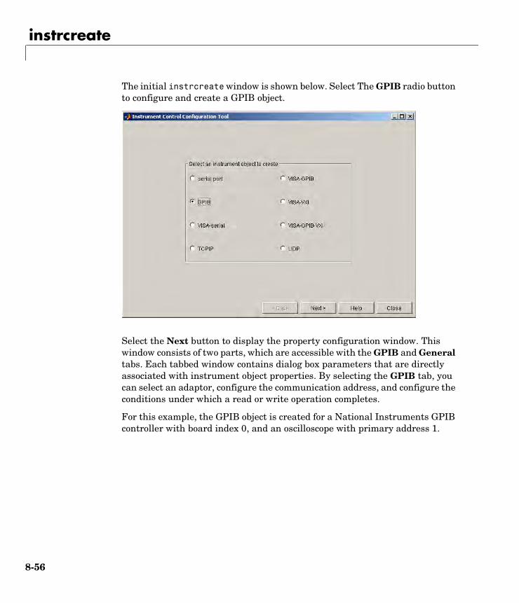
instrcreate
8-56
The initial instrcreate window is shown below. Select The GPIB radio button to configure and create a GPIB object.
Select the Next button to display the property configuration window. This window consists of two parts, which are accessible with the GPIB and General tabs. Each tabbed window contains dialog box parameters that are directly associated with instrument object properties. By selecting the GPIB tab, you can select an adaptor, configure the communication address, and configure the conditions under which a read or write operation completes.
For this example, the GPIB object is created for a National Instruments GPIB controller with board index 0, and an oscilloscope with primary address 1.
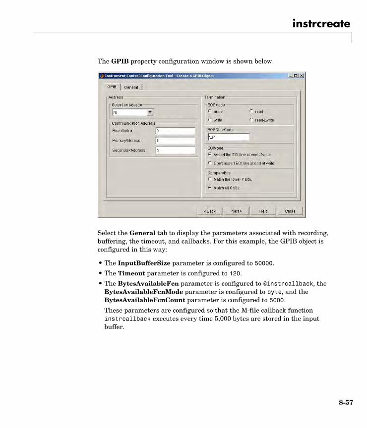
instrcreate
8-57
The GPIB property configuration window is shown below.
Select the General tab to display the parameters associated with recording, buffering, the timeout, and callbacks. For this example, the GPIB object is configured in this way:
• The InputBufferSize parameter is configured to 50000.
• The Timeout parameter is configured to 120.
• The BytesAvailableFcn parameter is configured to @instrcallback, the BytesAvailableFcnMode parameter is configured to byte, and the BytesAvailableFcnCount parameter is configured to 5000.
These parameters are configured so that the M-file callback function instrcallback executes every time 5,000 bytes are stored in the input buffer.
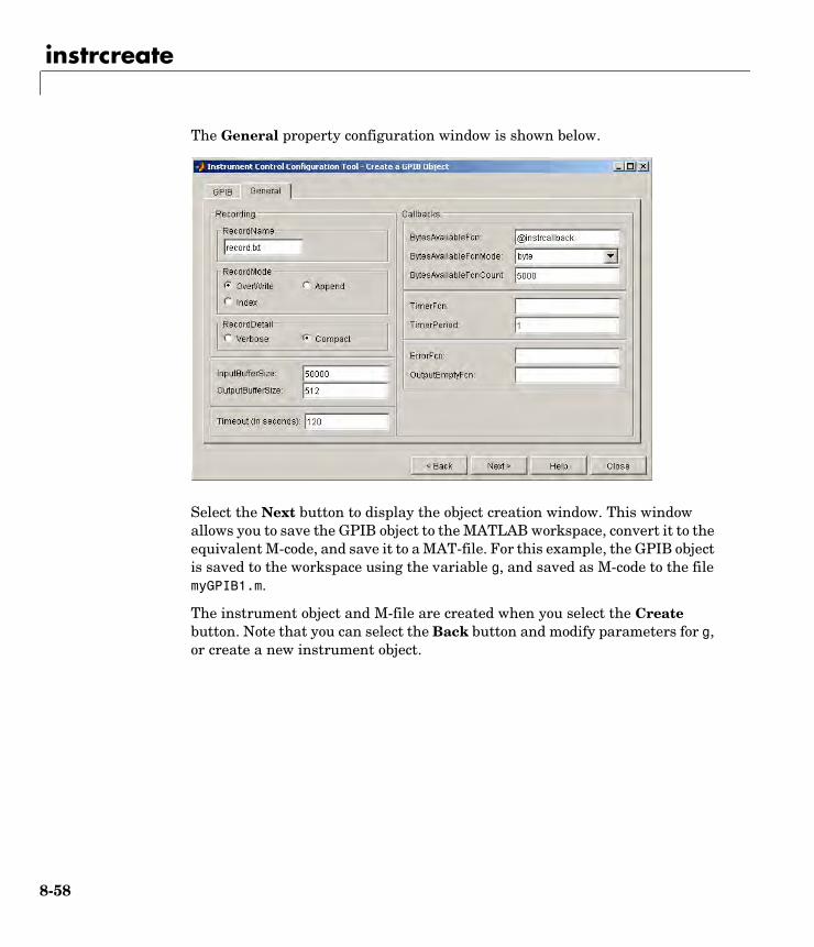
instrcreate
8-58
The General property configuration window is shown below.
Select the Next button to display the object creation window. This window allows you to save the GPIB object to the MATLAB workspace, convert it to the equivalent M-code, and save it to a MAT-file. For this example, the GPIB object is saved to the workspace using the variable g, and saved as M-code to the file myGPIB1.m.
The instrument object and M-file are created when you select the Create button. Note that you can select the Back button and modify parameters for g, or create a new instrument object.

instrcreate
8-59
The object creation window is shown below.
After the GPIB object is configured and created, you can use it to communicate with your instrument via the command line or via the Instrument Control ASCII Communication Tool, instrcomm. Note that instrcomm does not support asynchronous read and write operations. Therefore, the bytes-available events will not be generated.
See Also Functionsinstrcomm
instrfind
8-60
8instrfindPurpose Return instrument objects from memory to the MATLAB workspace
Syntax out = instrfind out = instrfind('PropertyName',PropertyValue,...) out = instrfind(S)out = instrfind(obj,'PropertyName',PropertyValue,...)
Arguments
Description out = instrfind returns all valid instrument objects as an array to out.
out = instrfind('PropertyName',PropertyValue,...) returns an array of instrument objects whose property names and property values match those specified.
out = instrfind(S) returns an array of instrument objects whose property names and property values match those defined in the structure S. The field names of S are the property names, while the field values are the associated property values.
out = instrfind(obj,'PropertyName',PropertyValue,...) restricts the search for matching property name/property value pairs to the instrument objects listed in obj.
Remarks You must specify property values using the same format as the get function returns. For example, if get returns the Name property value as MyObject, instrfind will not find an object with a Name property value of myobject. However, this is not the case for properties that have a finite set of string values. For example, instrfind will find an object with a Parity property value of Even or even. You can use the propinfo function to determine if a property has a finite set of string values.
'PropertyName' A property name for obj.
PropertyValue A property value supported by PropertyName.
S A structure of property names and property values.
obj An instrument object, or an array of instrument objects.
out An array of instrument objects.

instrfind
8-61
You can use property name/property value string pairs, structures, and cell array pairs in the same call to instrfind.
Example Suppose you create the following two GPIB objects.
g1 = gpib('ni',0,1);g2 = gpib('ni',0,2);g2.EOSCharCode = 'CR';fopen([g1 g2])
You can use instrfind to return instrument objects based on property values.
out1 = instrfind('Type','gpib');out2 = instrfind({'Type','EOSCharCode'},{'gpib','CR'});
You can also use instrfind to return cleared instrument objects to the MATLAB workspace.
clear g1 g2newobjs = instrfind
Instrument Object Array Index: Type: Status: Name: 1 gpib open GPIB0-1 2 gpib open GPIB0-2
Assign the instrument objects their original names.
g1 = newobjs(1);g2 = newobjs(2);
Close both g1 and g2.
fclose(newobjs)
See Also Functionsclear, get, propinfo

instrhelp
8-62
8instrhelpPurpose Return instrument object function and property help
Syntax instrhelpinstrhelp('name')out = instrhelp('name') instrhelp(obj)instrhelp(obj,'name')out = instrhelp(obj,'name')
Arguments
Description instrhelp returns a complete listing of instrument object functions, with a brief description of each.
instrhelp('name') returns help for the function, property, or interface specified by name.
You can return specific instrument object information by specifying name in the form object/function or object.property. For example, to return the help for a serial port object's fprintf function, name would be serial/fprintf. To return the help for a serial port object's Parity property, name would be serial.parity.
out = instrhelp('name') returns the help text to out.
instrhelp(obj) returns a complete listing of functions and properties for obj, with a brief description of each. Help for the constructor is also returned.
instrhelp(obj,'name') returns help for the function or property specified by name associated with obj.
out = instrhelp(obj,'name') returns the help text to out.
'name' A function name, property name, or interface type.
obj An instrument object.
out Contains the text string.
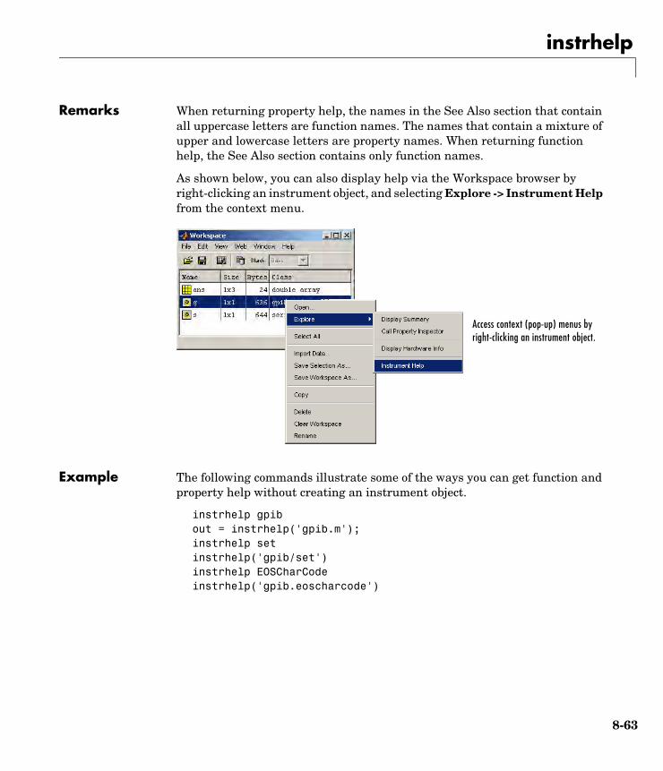
instrhelp
8-63
Remarks When returning property help, the names in the See Also section that contain all uppercase letters are function names. The names that contain a mixture of upper and lowercase letters are property names. When returning function help, the See Also section contains only function names.
As shown below, you can also display help via the Workspace browser by right-clicking an instrument object, and selecting Explore -> Instrument Help from the context menu.
Example The following commands illustrate some of the ways you can get function and property help without creating an instrument object.
instrhelp gpibout = instrhelp('gpib.m');instrhelp setinstrhelp('gpib/set')instrhelp EOSCharCodeinstrhelp('gpib.eoscharcode')
Access context (pop-up) menus by right-clicking an instrument object.

instrhelp
8-64
The following commands illustrate some of the ways you can get function and property help for an existing instrument object.
g = gpib('ni',0,1);instrhelp(g)instrhelp(g,'EOSMode');out = instrhelp(g,'trigger');
See Also Functionspropinfo
instrhwinfo
8-65
8instrhwinfoPurpose Return information about available hardware
Syntax out = instrhwinfoout = instrhwinfo('interface') out = instrhwinfo('interface','adaptor')out = instrhwinfo('interface','adaptor','type')out = instrhwinfo(obj)out = instrhwinfo(obj,'FieldName')
Arguments
Description out = instrhwinfo returns hardware information to the structure out. This information includes the toolbox version, MATLAB version and supported interfaces.
out = instrhwinfo('interface') returns information related to the interface specified by interface. interface can be serial, gpib, tcpip, udp, or visa. For the GPIB and VISA interfaces, the information includes the installed adaptors. For the serial port interface, the information includes the available ports and the object constructor name. For the TCP/IP and UDP interfaces, the information includes the local host address.
out = instrhwinfo('interface','adaptor') returns information related to the adaptor specified by adaptor, and for the interface specified by interface. interface can be gpib or visa. The returned information includes the adaptor version and available hardware. The GPIB adaptors are agilent, cec, iotech, keithley, mcc, and ni. The VISA adaptors are agilent, ni, and tek.
out = instrhwinfo('interface','adaptor','type') returns a structure, out, which contains information on the specified type, type. interface can only be visa. adaptor can be agilent, ni, or tek. type can be gpib, vxi, gpib-vxi, serial, or rsib.
'interface' A supported instrument interface.
'adaptor' A supported GPIB or VISA adaptor.
obj An instrument object or array of instrument objects.
'FieldName' A field name or cell array of field names associated with obj.
out A structure or array containing hardware information.

instrhwinfo
8-66
out = instrhwinfo(obj) returns information on the adaptor and vendor-supplied DLL associated with the VISA or GPIB object obj. If obj is a serial port, TCP/IP, or UDP object, then JAR file information is returned. If obj is an array of instrument objects, then out is a 1-by-n cell array of structures where n is the length of obj.
out = instrhwinfo(obj,'FieldName') returns hardware information for the field name specified by FieldName. FieldName can be a single string or a cell array of strings. out is a m-by-n cell array where m is the length of obj and n is the length of FieldName. You can return the supported values for FieldName using the instrhwinfo(obj) syntax.
Remarks As shown below, you can also display hardware information via the Workspace browser by right-clicking an instrument object, and selecting Explore -> Display Hardware Info from the context menu.
Example The following commands illustrate some of the ways you can get hardware-related information without creating an instrument object.
out1 = instrhwinfo;out2 = instrhwinfo('serial');out3 = instrhwinfo('gpib','ni');out4 = instrhwinfo('visa','agilent');
Access context (pop-up) menus by right-clicking an instrument object.
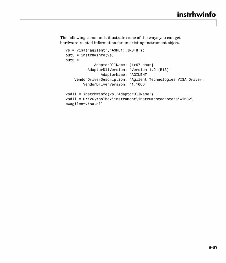
instrhwinfo
8-67
The following commands illustrate some of the ways you can get hardware-related information for an existing instrument object.
vs = visa('agilent','ASRL1::INSTR');out5 = instrhwinfo(vs)out5 = AdaptorDllName: [1x67 char] AdaptorDllVersion: 'Version 1.2 (R13)' AdaptorName: 'AGILENT' VendorDriverDescription: 'Agilent Technologies VISA Driver' VendorDriverVersion: '1.1000'
vsdll = instrhwinfo(vs,'AdaptorDllName')vsdll = D:\V6\toolbox\instrument\instrumentadaptors\win32\ mwagilentvisa.dll
instrreset
8-68
8instrresetPurpose Disconnect and delete all instrument objects
Syntax instrreset
Description instrreset disconnects and deletes all instrument objects.
Remarks If data is being written or read asynchronously, the asynchronous operation is stopped.
instrreset is equivalent to issuing the stopasync (if needed), fclose, and delete functions for all instrument objects.
When you delete an instrument object, it becomes invalid. Because you cannot connect an invalid object to the instrument, you should remove it from the workspace with the clear command.
See Also Functionsclear, delete, fclose, isvalid, stopasync
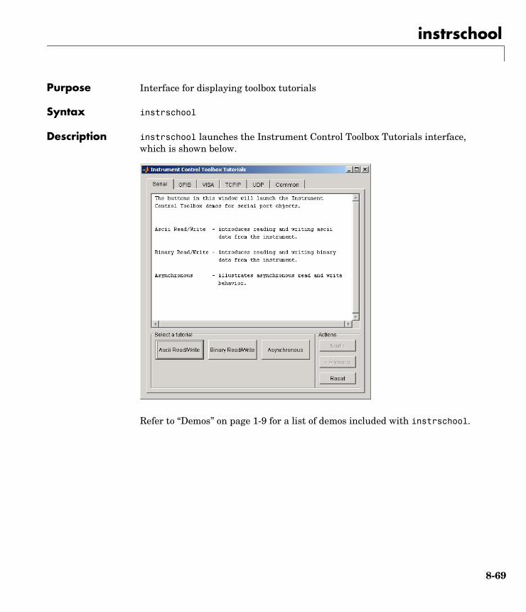
instrschool
8-69
8instrschoolPurpose Interface for displaying toolbox tutorials
Syntax instrschool
Description instrschool launches the Instrument Control Toolbox Tutorials interface, which is shown below.
Refer to “Demos” on page 1-9 for a list of demos included with instrschool.
isvalid
8-70
8isvalidPurpose Determine if instrument objects are valid
Syntax out = isvalid(obj)
Arguments
Description out = isvalid(obj) returns the logical array out, which contains a 0 where the elements of obj are invalid instrument objects and a 1 where the elements of obj are valid instrument objects.
Remarks obj becomes invalid after it is removed from memory with the delete function. Because you cannot connect an invalid object to the instrument, you should remove it from the workspace with the clear command.
Example Suppose you create the following two GPIB objects:
g1 = gpib('ni',0,1);g2 = gpib('ni',0,2);
g2 becomes invalid after it is deleted.
delete(g2)
isvalid verifies that g1 is valid and g2 is invalid.
garray = [g1 g2];isvalid(garray)ans = 1 0
See Also Functionsclear, delete
obj An instrument object or array of instrument objects.
out A logical array.
length
8-71
8lengthPurpose Length of instrument object array
Syntax length(obj)
Arguments
Description length(obj) returns the length of obj. It is equivalent to the command max(size(obj)).
See Also Functionsinstrhelp, size
obj An instrument object or an array of instrument objects.

load
8-72
8loadPurpose Load instrument objects and variables into the MATLAB workspace
Syntax load filenameload filename obj1 obj2 ...out = load('filename','obj1','obj2',...)
Arguments
Description load filename returns all variables from the MAT-file specified by filename into the MATLAB workspace.
load filename obj1 obj2 ... returns the instrument objects specified by obj1 obj2... from the MAT-file filename into the MATLAB workspace.
out = load('filename','obj1','obj2',...) returns the specified instrument objects from the MAT-file filename as a structure to out instead of directly loading them into the workspace. The field names in out match the names of the loaded instrument objects.
Remarks Values for read-only properties are restored to their default values upon loading. For example, the Status property is restored to closed. To determine if a property is read-only, examine its reference pages or use the propinfo function.
Example Suppose you create the GPIB objects g1 and g2, configure a few properties for g1, and connect both objects to their associated instruments.
g1 = gpib('ni',0,1);g2 = gpib('ni',0,2);set(g1,'EOSMode','read','EOSCharCode','CR')fopen([g1 g2])
filename The MAT-file name.
obj1 obj2 ... Instrument objects or arrays of instrument objects.
out A structure containing the specified instrument objects.
load
8-73
The read-only Status property is automatically configured to open.
get([g1 g2],'Status')ans = 'open' 'open'
Save g1 and g2 to the file MyObject.mat, and then load the objects into the MATLAB workspace.
save MyObject g1 g2load MyObject g1 g2
Values for read-only properties are restored to their default values upon loading, while all other property values are honored.
get([g1 g2],{'EOSMode','EOSCharCode','Status'})ans = 'read' 'CR' 'closed' 'none' 'LF' 'closed'
See Also Functionsinstrhelp, propinfo, save
memmap
8-74
8memmapPurpose Map memory for low-level memory read and write operations
Syntax memmap(obj,'adrspace',offset,size)
Arguments
Description memmap(obj,'adrspace',offset,size) maps the amount of memory specified by size in address space, adrspace with an offset, offset. You can configure adrspace to A16 (A16 address space), A24 (A24 address space), or A32 (A32 address space).
Remarks Before you can map memory, obj must be connected to the instrument with the fopen function. A connected instrument object has a Status property value of open. An error is returned if you attempt to map memory while obj is not connected to the instrument.
To unmap the memory, use the memunmap function. If memory is mapped and fclose is called, the memory is unmapped before the object is disconnected from the instrument.
The MappedMemorySize property returns the size of the memory space mapped. You must map the memory space before using the mempoke or mempeek function.
Example Create the VISA-VXI object vv associated with a VXI chassis with index 0, and an Agilent E1432A digitizer with logical address 130.
vv = visa('agilent','VXI0::130::INSTR');fopen(vv)
Use memmap to map 16 bytes in the A16 address space.
memmap(vv,'A16',0,16)
obj A VISA-VXI or VISA-GPIB-VXI object.
'adrspace' The memory address space.
offset Offset for the memory address space.
size Number of bytes to map.
memmap
8-75
Read the first and second instrument registers.
reg1 = mempeek(vv,0,'uint16');reg2 = mempeek(vv,2,'uint16');
Unmap the memory and disconnect vv from the instrument.
memunmap(vv)fclose(vv)
See Also Functionsfopen, fclose, mempeek, mempoke, memunmap
PropertiesMappedMemorySize, Status
mempeek
8-76
8mempeekPurpose Low-level memory read from VXI register
Syntax out = mempeek(obj,offset)out = mempeek(obj,offset,'precision')
Arguments
Description out = mempeek(obj,offset) reads a uint8 value from the mapped memory space specified by offset for the object obj. The value is returned to out.
out = mempeek(obj,offset,'precision') reads the number of bits specified by precision, from the mapped memory space specified by offset. precision can be uint8, uint16, or uint32, which instructs mempeek to read 8-, 16-, or 32-bit values, respectively. precision can also be single, which instructs mempeek to read single precision values.
Remarks Before you can read from the VXI register, obj must be connected to the instrument with the fopen function. A connected instrument object has a Status property value of open. An error is returned if you attempt a read operation while obj is not connected to the instrument.
You must map the memory space using the memmap function before using mempeek. The MappedMemorySize property returns the size of the memory space mapped.
offset indicates the offset in the mapped memory space from which the data is read. For example, if the mapped memory space begins at 200H, the offset is 2, and the precision is uint8, then the data is read from memory location 202H. If the precision is uint16, the data is read from 202H and 203H.
To increase speed, mempeek does not return error messages from the instrument.
obj A VISA-VXI or VISA-GPIB-VXI object.
offset The offset in the mapped memory space from which the data is read.
'precision' The number of bits to read from the memory address.
out An array containing the returned value.
mempeek
8-77
Example Create the VISA-VXI object vv associated with a VXI chassis with index 0, and an Agilent E1432A digitizer with logical address 130.
vv = visa('agilent','VXI0::130::INSTR');fopen(vv)
Use memmap to map 16 bytes in the A16 address space.
memmap(vv,'A16',0,16)
Perform a low-level read the first and second instrument registers.
reg1 = mempeek(vv,0,'uint16')reg1 = 53247reg2 = mempeek(vv,2,'uint16')reg2 = 20993
Unmap the memory and disconnect vv from the instrument.
memunmap(vv)fclose(vv)
Refer to “Example: Using High-Level Memory Functions” on page 4-16 for a description of the first four registers of the E1432A digitizer.
See Also Functionsfopen, memmap, mempoke, memunmap
PropertiesMappedMemorySize, MemoryIncrement, Status
mempoke
8-78
8mempokePurpose Low-level memory write to VXI register
Syntax mempoke(obj,data,offset)mempoke(obj,data,offset,'precision')
Arguments
Description mempoke(obj,data,offset) writes the uint8 value specified by data to the mapped memory address specified by offset for the object obj.
mempoke(obj,data,offset,'precision') writes data using the number of bits specified by precision. precision can be uint8, uint16, or uint32, which instructs mempoke to write data as 8-, 16-, or 32-bit values, respectively. precision can also be single, which instructs mempoke to write data as single precision values.
Remarks Before you can write to the VXI register, obj must be connected to the instrument with the fopen function. A connected instrument object has a Status property value of open. An error is returned if you attempt a write operation while obj is not connected to the instrument.
You must map the memory space using the memmap function before using mempoke. The MappedMemorySize property returns the size of the memory space mapped.
offset indicates the offset in the mapped memory space to which the data is written. For example, if the mapped memory space begins at 200H, the offset is 2, and the precision is uint8, then the data is written to memory location 202H. If the precision is uint16, the data is written to 202H and 203H.
To increase speed, mempoke does not return error messages from the instrument.
obj A VISA-VXI or VISA-GPIB-VXI object.
data The data written to the memory address.
offset The offset in the mapped memory space to which the data is written.
'precision' The number of bits to write to the memory address.
mempoke
8-79
Example Create the VISA-VXI object vv associated with a VXI chassis with index 0, and an Agilent E1432A digitizer with logical address 130.
vv = visa('agilent','VXI0::130::INSTR');fopen(vv)
Use memmap to map 16 bytes in the A16 address space.
memmap(vv,'A16',0,16)
Perform a low-level write to the fourth instrument register, which has an offset of 6.
mempoke(vv,45056,6,'uint16')
Unmap the memory and disconnect vv from the instrument.
memunmap(vv)fclose(vv)
Refer to “Example: Using High-Level Memory Functions” on page 4-16 for a description of the first four registers of the E1432A digitizer.
See Also Functionsfopen, memmap, mempeek
PropertiesMappedMemorySize, MemoryIncrement, Status
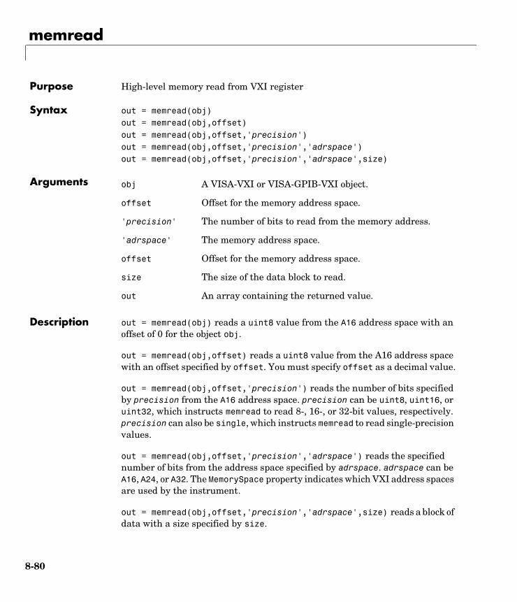
memread
8-80
8memreadPurpose High-level memory read from VXI register
Syntax out = memread(obj)out = memread(obj,offset)out = memread(obj,offset,'precision')out = memread(obj,offset,'precision','adrspace')out = memread(obj,offset,'precision','adrspace',size)
Arguments
Description out = memread(obj) reads a uint8 value from the A16 address space with an offset of 0 for the object obj.
out = memread(obj,offset) reads a uint8 value from the A16 address space with an offset specified by offset. You must specify offset as a decimal value.
out = memread(obj,offset,'precision') reads the number of bits specified by precision from the A16 address space. precision can be uint8, uint16, or uint32, which instructs memread to read 8-, 16-, or 32-bit values, respectively. precision can also be single, which instructs memread to read single-precision values.
out = memread(obj,offset,'precision','adrspace') reads the specified number of bits from the address space specified by adrspace. adrspace can be A16, A24, or A32. The MemorySpace property indicates which VXI address spaces are used by the instrument.
out = memread(obj,offset,'precision','adrspace',size) reads a block of data with a size specified by size.
obj A VISA-VXI or VISA-GPIB-VXI object.
offset Offset for the memory address space.
'precision' The number of bits to read from the memory address.
'adrspace' The memory address space.
offset Offset for the memory address space.
size The size of the data block to read.
out An array containing the returned value.
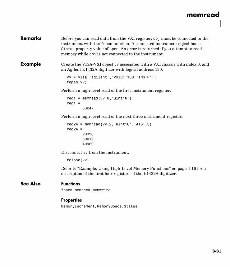
memread
8-81
Remarks Before you can read data from the VXI register, obj must be connected to the instrument with the fopen function. A connected instrument object has a Status property value of open. An error is returned if you attempt to read memory while obj is not connected to the instrument.
Example Create the VISA-VXI object vv associated with a VXI chassis with index 0, and an Agilent E1432A digitizer with logical address 130.
vv = visa('agilent','VXI0::130::INSTR');fopen(vv)
Perform a high-level read of the first instrument register.
reg1 = memread(vv,0,'uint16')reg1 = 53247
Perform a high-level read of the next three instrument registers.
reg24 = memread(vv,2,'uint16','A16',3)reg24 = 20993 50012 40960
Disconnect vv from the instrument.
fclose(vv)
Refer to “Example: Using High-Level Memory Functions” on page 4-16 for a description of the first four registers of the E1432A digitizer.
See Also Functionsfopen, mempeek, memwrite
PropertiesMemoryIncrement, MemorySpace, Status
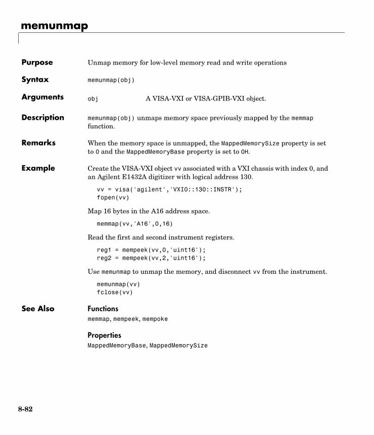
memunmap
8-82
8memunmapPurpose Unmap memory for low-level memory read and write operations
Syntax memunmap(obj)
Arguments
Description memunmap(obj) unmaps memory space previously mapped by the memmap function.
Remarks When the memory space is unmapped, the MappedMemorySize property is set to 0 and the MappedMemoryBase property is set to 0H.
Example Create the VISA-VXI object vv associated with a VXI chassis with index 0, and an Agilent E1432A digitizer with logical address 130.
vv = visa('agilent','VXI0::130::INSTR');fopen(vv)
Map 16 bytes in the A16 address space.
memmap(vv,'A16',0,16)
Read the first and second instrument registers.
reg1 = mempeek(vv,0,'uint16');reg2 = mempeek(vv,2,'uint16');
Use memunmap to unmap the memory, and disconnect vv from the instrument.
memunmap(vv)fclose(vv)
See Also Functionsmemmap, mempeek, mempoke
PropertiesMappedMemoryBase, MappedMemorySize
obj A VISA-VXI or VISA-GPIB-VXI object.
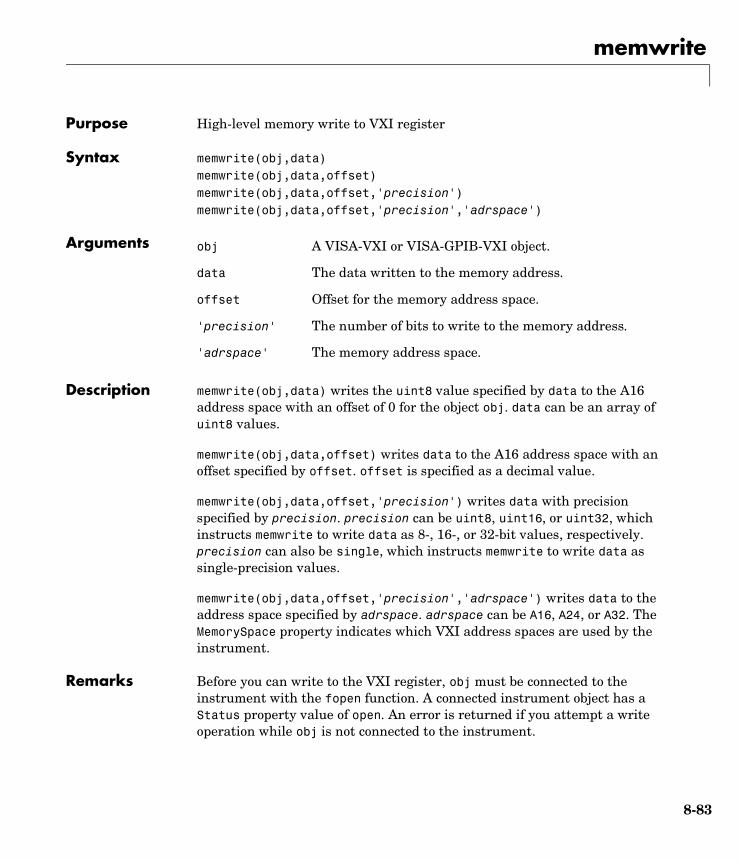
memwrite
8-83
8memwritePurpose High-level memory write to VXI register
Syntax memwrite(obj,data)memwrite(obj,data,offset)memwrite(obj,data,offset,'precision')memwrite(obj,data,offset,'precision','adrspace')
Arguments
Description memwrite(obj,data) writes the uint8 value specified by data to the A16 address space with an offset of 0 for the object obj. data can be an array of uint8 values.
memwrite(obj,data,offset) writes data to the A16 address space with an offset specified by offset. offset is specified as a decimal value.
memwrite(obj,data,offset,'precision') writes data with precision specified by precision. precision can be uint8, uint16, or uint32, which instructs memwrite to write data as 8-, 16-, or 32-bit values, respectively. precision can also be single, which instructs memwrite to write data as single-precision values.
memwrite(obj,data,offset,'precision','adrspace') writes data to the address space specified by adrspace. adrspace can be A16, A24, or A32. The MemorySpace property indicates which VXI address spaces are used by the instrument.
Remarks Before you can write to the VXI register, obj must be connected to the instrument with the fopen function. A connected instrument object has a Status property value of open. An error is returned if you attempt a write operation while obj is not connected to the instrument.
obj A VISA-VXI or VISA-GPIB-VXI object.
data The data written to the memory address.
offset Offset for the memory address space.
'precision' The number of bits to write to the memory address.
'adrspace' The memory address space.
memwrite
8-84
Example Create the VISA-VXI object vv associated with a VXI chassis with index 0, and an Agilent E1432A digitizer with logical address 130.
vv = visa('agilent','VXI0::130::INSTR');fopen(vv)
Perform a high-level write to the fourth instrument register, which has an offset of 6.
memwrite(vv,45056,6,'uint16','A16')
Disconnect vv from the instrument.
fclose(vv)
Refer to “Example: Using High-Level Memory Functions” on page 4-16 for a description of the first four registers of the E1432A digitizer.
See Also Functionsfopen, memread, mempoke
PropertiesMemoryIncrement, MemorySpace, Status
obj2mfile
8-85
8obj2mfilePurpose Convert instrument object to MATLAB code
Syntax obj2mfile(obj,'filename') obj2mfile(obj,'filename','syntax') obj2mfile(obj,'filename','mode')obj2mfile(obj,'filename','syntax','mode')
Arguments
Description obj2mfile(obj,'filename') converts obj to the equivalent MATLAB code using the set syntax and saves the code to filename. Only those properties not set to their default value are saved.
obj2mfile(obj,'filename','syntax') converts obj to the equivalent MATLAB code using the syntax specified by syntax. You can specify syntax to be set or dot. set uses the set syntax, while dot uses the dot notation.
obj2mfile(obj,'filename','mode') converts the properties specified by mode. You can specify mode to be all or modified. If mode is all, then all properties are converted to code. If mode is modified, then only those properties not set to their default value are converted to code.
obj2mfile(obj,'filename','syntax','mode') converts the specified properties to code using the specified syntax.
Remarks You can recreate a saved instrument object by typing the name of the M-file at the MATLAB command line.
obj An instrument object or an array of instrument objects.
'filename' The name of the file that the MATLAB code is written to. You can specify the full pathname. If an extension is not specified, the .m extension is used.
'syntax' Syntax of the converted MATLAB code. By default, the set syntax is used. If dot is specified, then the dot notation is used.
'mode' Specifies whether all properties are converted to code, or only modified properties are converted to code.
obj2mfile
8-86
If the UserData property is not empty or if any of the callback properties are set to a cell array of values or a function handle, then the data stored in those properties is written to a MAT-file when the instrument object is converted and saved. The MAT-file has the same name as the M-file containing the instrument object code (see the example below).
Read-only properties are restored with their default values. For example, suppose an instrument object is saved with a Status property value of open. When the object is recreated, Status is set to its default value of closed.
Example Suppose you create the GPIB object g, and configure several property values.
g = gpib('ni',0,1);set(g,'Tag','MyGPIB object','EOSMode','read','EOSCharCode','CR')set(g,'UserData',{'test',2,magic(10)})
The following command writes MATLAB code to the files MyGPIB.m and MyGPIB.mat.
obj2mfile(g,'MyGPIB.m','dot')
MyGPIB.m contains code that recreates the commands shown above using the dot notation for all properties that have their default values changed. Because UserData is set to a cell array of values, this property appears in MyGPIB.m as
obj1.UserData = userdata1;
It is saved in MyGPIB.mat as
userdata = {'test', 2, magic(10)};
To recreate g in the MATLAB workspace using a new variable, gnew:
gnew = MyGPIB;
The associated MAT-file, MyGPIB.mat, is automatically run and UserData is assigned the appropriate values.
gnew.UserDataans = 'test' [2] [10x10 double]
See Also Functionspropinfo
propinfo
8-87
8propinfoPurpose Return instrument object property information
Syntax out = propinfo(obj)out = propinfo(obj,'PropertyName')
Arguments
Description out = propinfo(obj) returns the structure out with field names given by the property names for obj. Each property name in out contains the fields shown below.
out = propinfo(obj,'PropertyName') returns the structure out for the property specified by PropertyName. The field names of out are given in the
obj An instrument object.
'PropertyName' A property name or cell array of property names.
out A structure containing property information.
Field Name Description
Type The property data type. Possible values are any, ASCII value, callback, double, string, and struct.
Constraint The type of constraint on the property value. Possible values are ASCII value, bounded, callback, enum, and none.
ConstraintValue Property value constraint. The constraint can be a range of valid values or a list of valid string values.
DefaultValue The property default value.
ReadOnly The condition under which a property is read-only. Possible values are always, never, whileOpen, and whileRecording.
InterfaceSpecific
If the property is interface-specific, a 1 is returned. If a 0 is returned, the property is supported for all interfaces.
propinfo
8-88
table shown above. If PropertyName is a cell array of property names, a cell array of structures is returned for each property.
Remarks You can get help for instrument object properties with the instrhelp function.
You can display all instrument object property names and their current values using the get function. You can display all configurable properties and their possible values using the set function.
When you specify property names, you can do so without regard to case, and you can make use of property name completion. For example, if g is a GPIB object, then the following commands are all valid.
out = propinfo(g,'EOSMode');out = propinfo(g,'eosmode');out = propinfo(g,'EOSM');
Example To return all property information for the GPIB object g:
g = gpib('ni',0,1);out = propinfo(g);
To display all the property information for the InputBufferSize property:
out.InputBufferSizeans = Type: 'double' Constraint: 'none' ConstraintValue: '' DefaultValue: 512 ReadOnly: 'whileOpen'InterfaceSpecific: 0
To display the default value for the EOSMode property:
out.EOSMode.DefaultValueans =none
See Also Functionsget, instrhelp, set

query
8-89
8queryPurpose Write text to the instrument, and read data from the instrument
Syntax out = query(obj,'cmd')out = query(obj,'cmd','wformat')out = query(obj,'cmd','wformat','rformat')[out,count] = query(...)[out,count,msg] = query(...)
Arguments
Description out = query(obj,'cmd') writes the string cmd to the instrument connected to obj. The data read from the instrument is returned to out. By default, the %s\n format is used for cmd, and the %c format is used for the returned data.
out = query(obj,'cmd','wformat') writes the string cmd using the format specified by wformat.
wformat is a C language conversion specification. Conversion specifications involve the % character and the conversion characters d, i, o, u, x, X, f, e, E, g, G, c, and s. Refer to the sprintf file I/O format specifications or a C manual for more information.
out = query(obj,'cmd','wformat','rformat') writes the string cmd using the format specified by wformat. The data read from the instrument is returned to out using the format specified by rformat.
rformat is a C language conversion specification. The supported conversion specifications are identical to those supported by wformat.
obj An instrument object.
'cmd' String that is written to the instrument.
'wformat' Format for written data.
'rformat' Format for read data.
out Contains data read from the instrument.
count The number of values read.
msg A message indicating if the read operation was unsuccessful.
query
8-90
[A,count] = query(...) returns the number of values read to count.
[A,count,msg] = query(...) returns a warning message to msg if the read operation did not complete successfully.
Remarks Before you can write or read data, obj must be connected to the instrument with the fopen function. A connected instrument object has a Status property value of open. An error is returned if you attempt to perform a query operation while obj is not connected to the instrument.
query operates only in synchronous mode, and blocks the command line until the write and read operations complete execution.
Using query is equivalent to using the fprintf and fgets functions. The rules for completing a write operation are described in the fprintf reference pages. The rules for completing a read operation are described in the fgets reference pages.
Example This example creates the GPIB object g, connects g to a Tektronix TDS 210 oscilloscope, writes and reads text data using query, and then disconnects g from the instrument.
g = gpib('ni',0,1);fopen(g)idn = query(g,'*IDN?')idn =TEKTRONIX,TDS 210,0,CF:91.1CT FV:v1.16 TDS2CM:CMV:v1.04fclose(g)
See Also Functionsfopen, fprintf, fgets, sprintf
PropertiesStatus
readasync
8-91
8readasyncPurpose Read data asynchronously from the instrument
Syntax readasync(obj)readasync(obj,size)
Arguments
Description readasync(obj) initiates an asynchronous read operation.
readasync(obj,size) asynchronously reads, at most, the number of bytes specified by size. If size is greater than the difference between the InputBufferSize property value and the BytesAvailable property value, an error is returned.
Remarks Before you can read data, you must connect obj to the instrument with the fopen function. A connected instrument object has a Status property value of open. An error is returned if you attempt to perform a read operation while obj is not connected to the instrument.
For serial port, TCP/IP, UDP, and VISA-serial objects, you should use readasync only when you configure the ReadAsyncMode property to manual. readasync is ignored if used when ReadAsyncMode is continuous.
The TransferStatus property indicates if an asynchronous read or write operation is in progress. For all instrument objects, you cannot use readasync while a read operation is in progress. For serial port and VISA-serial objects, you can write data while an asynchronous read is in progress because serial ports have separate read and write pins. You can stop asynchronous read and write operations with the stopasync function.
You can monitor the amount of data stored in the input buffer with the BytesAvailable property. Additionally, you can use the BytesAvailableFcn property to execute an M-file callback function when the terminator or the specified amount of data is read.
obj An instrument object.
size The number of bytes to read from the instrument.
readasync
8-92
Rules for Completing an Asynchronous Read OperationAn asynchronous read operation with readasync completes when one of these conditions is met:
• The terminator is read. For serial port, TCP/IP, UDP, and VISA-serial objects, the terminator is given by the Terminator property. Note that for UDP objects, DatagramTerminateMode must be off.
For all other instrument objects except VISA-RSIB, the terminator is given by the EOSCharCode property.
• The time specified by the Timeout property passes.
• The specified number of bytes is read.
• The input buffer is filled.
• A datagram has been received (UDP objects only if DatagramTerminateMode is on)
• The EOI line is asserted (GPIB and VXI instruments only).
For serial port, TCP/IP, UDP, and VISA-serial objects, readasync can be slow because it checks for the terminator. To increase speed, you might want to configure ReadAsyncMode to continuous and continuously return data to the input buffer as soon as it is available from the instrument.
Example This example creates the serial port object s, connects s to a Tektronix TDS 210 oscilloscope, configures s to read data asynchronously only if readasync is issued, and configures the instrument to return the peak-to-peak value of the signal on channel 1.
s = serial('COM1');fopen(s)s.ReadAsyncMode = 'manual';fprintf(s,'Measurement:Meas1:Source CH1')fprintf(s,'Measurement:Meas1:Type Pk2Pk')fprintf(s,'Measurement:Meas1:Value?')
Initially, there is no data in the input buffer.
s.BytesAvailableans = 0
readasync
8-93
Begin reading data asynchronously from the instrument using readasync. When the read operation is complete, return the data to the MATLAB workspace using fscanf.
readasync(s)s.BytesAvailableans = 15out = fscanf(s)out =2.0399999619E0fclose(s)
See Also Functionsfopen, stopasync
PropertiesBytesAvailable, BytesAvailableFcn, ReadAsyncMode, Status, TransferStatus

record
8-94
8recordPurpose Record data and event information to a file
Syntax record(obj)record(obj,'switch')
Arguments
Description record(obj) toggles the recording state for obj.
record(obj,'switch') initiates or terminates recording for obj. switch can be on or off. If switch is on, recording is initiated. If switch is off, recording is terminated.
Remarks Before you can record information to disk, obj must be connected to the instrument with the fopen function. A connected instrument object has a Status property value of open. An error is returned if you attempt to record information while obj is not connected to the instrument. Each instrument object must record information to a separate file. Recording is automatically terminated when obj is disconnected from the instrument with fclose.
The RecordName and RecordMode properties are read-only while obj is recording, and must be configured before using record.
For a detailed description of the record file format and the properties associated with recording data and event information to a file, refer to “Debugging: Recording Information to Disk” on page 7-5.
Example This example creates the GPIB object g, connects g to the instrument, and configures g to record detailed information to the disk file MyGPIBFile.txt.
g = gpib('ni',0,1);fopen(g)g.RecordDetail = 'verbose';g.RecordName = 'MyGPIBFile.txt';
obj An instrument object.
'switch' Switch recording capabilities on or off.

record
8-95
Initiate recording, write the *IDN? command to the instrument, and read back the identification information.
record(g,'on')fprintf(g,'*IDN?')out = fscanf(g);
Terminate recording and disconnect g from the instrument.
record(g,'off')fclose(g)
See Also Functionsfclose, fopen, propinfo
PropertiesRecordMode, RecordName, RecordStatus, Status
resolvehost
8-96
8resolvehostPurpose Return network name or network address
Syntax name = resolvehost('host')[name,address] = resolvehost('host')out = resolvehost('host','returntype')
Arguments
Description name = resolvehost('host') returns the name of the specified host. You can specify host as either a network name or a network address. For example, www.mathworks.com is a network name and 144.212.100.10 is a network address.
[name,address] = resolvehost('host') returns the name and address of the specified host.
out = resolvehost('host','returntype') returns the host name if returntype is name and returns the host address if returntype is address.
Example The following commands show how you can return the host name and address.
[name,address] = resolvehost('144.212.100.10')name = resolvehost('144.212.100.10','name')address = resolvehost('www.mathworks.com','address')
See Also Functionstcpip, udp
'host' The network name or network address of host.
'returntype' Return either the name or address of host
name Network name of host
address Network address of host
save
8-97
8savePurpose Save instrument objects and variables to a MAT-file
Syntax save filenamesave filename obj1 obj2...
Arguments
Description save filename saves all MATLAB variables to the MAT-file filename. If an extension is not specified for filename, then a .mat extension is used.
save filename obj1 obj2,... saves the instrument objects obj1 obj2 ... to the MAT-file filename.
Remarks You can use save in the functional form as well as the command form shown above. When using the functional form, you must specify the filename and instrument objects as strings. For example, to save the serial port object s to the file MySerial.mat:
s = serial('COM1');save('MySerial','s')
Any data that is associated with the instrument object is not automatically stored in the MAT-file. For example, suppose there is data in the input buffer for obj. To save that data to a MAT-file, you must bring the data into the MATLAB workspace using one of the synchronous read functions, and then save the data to the MAT-file using a separate variable name. You can also save data to a text file with the record function.
You return objects and variables to the MATLAB workspace with the load command. Values for read-only properties are restored to their default values upon loading. For example, the Status property is restored to closed. To determine if a property is read-only, examine its reference pages or use the propinfo function.
filename The MAT-file name.
obj1 obj2... Instrument objects or arrays of instrument objects.
save
8-98
Example This example illustrates how to use the command form and the functional form of save.
s = serial('COM1');set(s,'BaudRate',2400,'StopBits',1)save MySerial1 sset(s,'BytesAvailableFcn',@mycallback)save('MySerial2','s')
See Also Functionsinstrhelp, load, propinfo, record
PropertiesStatus

scanstr
8-99
8scanstrPurpose Read data from the instrument, format as text, and parse
Syntax A = scanstr(obj)A = scanstr(obj,'delimiter')A = scanstr(obj,'delimiter','format')[A,count] = scanstr(...)[A,count,msg] = scanstr(...)
Arguments
Description A = scanstr(obj) reads formatted data from the instrument connected to obj, parses the data using both a comma and a semicolon delimiter, and returns the data to the cell array A. Each element of the cell array is determined to be either a double or a string.
A = scanstr(obj,'delimiter') parses the data into separate variables based on the specified delimiter. delimiter can be a single character or a string array. If delimiter is a string array, then each character in the array is used as a delimiter.
A = scanstr(obj,'delimiter','format') converts the data according to the specified format. A can be a matrix or a cell array depending on format. See the textread M-file help for complete details. format is a string containing C language conversion specifications.
Conversion specifications involve the % character and the conversion characters d, i, o, u, x, X, f, e, E, g, G, c, and s. See the sscanf file I/O format specifications or a C manual for complete details.
If format is not specified, then the best format (either a double or a string) is chosen.
obj An instrument object.
'delimiter' One or more delimiters used to parse the data.
'format' C language conversion specification.
A Data read from the instrument and formatted as text.
count The number of values read.
msg A message indicating if the read operation was unsuccessful.
scanstr
8-100
[A,count] = scanstr(...) returns the number of values read to count.
[A,count,msg] = scanstr(...) returns a warning message to msg if the read operation did not complete successfully.
Remarks Before you can read data from the instrument, it must be connected to obj with the fopen function. A connected instrument object has a Status property value of open. An error is returned if you attempt to perform a read operation while obj is not connected to the instrument.
If msg is not included as an output argument and the read operation was not successful, then a warning message is returned to the command line.
The ValuesReceived property value is increased by the number of values read — including the terminator — each time scanstr is issued.
Example Create the GPIB object g associated with a National Instruments board with index 0 and primary address 2, and connect g to a Tektronix TDS 210 oscilloscope.
g = gpib('ni',0,2);fopen(g)
Return identification information to separate elements of a cell array using the default delimiters.
fprintf(g,'*IDN?');idn = scanstr(g)idn = 'TEKTRONIX' 'TDS 210' [ 0] 'CF:91.1CT FV:v1.16 TDS2CM:CMV:v1.04'
See Also Functionsfopen, fscanf, instrhelp, sscanf, textread
PropertiesEOSCharCode, EOSMode, Status, Terminator, ValuesReceived
serial
8-101
8serialPurpose Create a serial port object
Syntax obj = serial('port')obj = serial('port','PropertyName',PropertyValue,...)
Arguments
Description obj = serial('port') creates a serial port object associated with the serial port specified by port. If port does not exist, or if it is in use, you will not be able to connect the serial port object to the instrument with the fopen function.
obj = serial('port','PropertyName',PropertyValue,...) creates a serial port object with the specified property names and property values. If an invalid property name or property value is specified, an error is returned and the serial port object is not created.
Remarks At any time, you can use the instrhelp function to view a complete listing of properties and functions associated with serial port objects.
instrhelp serial
When you create a serial port object, these property values are automatically configured:
• The Type property is given by serial.
• The Name property is given by concatenating Serial with the port specified in the serial function.
• The Port property is given by the port specified in the serial function.
You can specify the property names and property values using any format supported by the set function. For example, you can use property name/property value cell array pairs. Additionally, you can specify property names
'port' The serial port name.
'PropertyName' A serial port property name.
PropertyValue A property value supported by PropertyName.
obj The serial port object.
serial
8-102
without regard to case, and you can make use of property name completion. For example, the following commands are all valid.
s = serial('COM1','BaudRate',4800)s = serial('COM1','baudrate',4800)s = serial('COM1','BAUD',4800)
Before you can communicate with the instrument, it must be connected to obj with the fopen function. A connected serial port object has a Status property value of open. An error is returned if you attempt a read or write operation while obj is not connected to the instrument. You can connect only one serial port object to a given serial port.
Example This example creates the serial port object s1 associated with the serial port COM1.
s1 = serial('COM1');
The Type, Name, and Port properties are automatically configured.
get(s1,{'Type','Name','Port'})ans = 'serial' 'Serial-COM1' 'COM1'
To specify properties during object creation:
s2 = serial('COM2','BaudRate',1200,'DataBits',7);
See Also Functionsfclose, fopen, propinfo
PropertiesName, Port, Status, Type
serialbreak
8-103
8serialbreakPurpose Send a break to the instrument
Syntax serialbreak(obj)serialbreak(obj,time)
Arguments
Description serialbreak(obj) sends a break of 10 milliseconds to the instrument connected to obj.
serialbreak(obj,time) sends a break to the instrument with a duration, in milliseconds, specified by time. Note that the duration of the break might be inaccurate under some operating systems.
Remarks For some instruments, the break signal provides a way to clear the hardware buffer.
Before you can send a break to the instrument, it must be connected to obj with the fopen function. A connected serial port object has a Status property value of open. An error is returned if you attempt to send a break while obj is not connected to the instrument.
serialbreak is a synchronous function, and blocks the command line until execution is complete.
If you issue serialbreak while data is being asynchronously written, an error is returned. In this case, you must call the stopasync function or wait for the write operation to complete.
See Also Functionsfopen, stopasync
PropertiesStatus
obj A serial port object.
time The duration of the break, in milliseconds.
set
8-104
8setPurpose Configure or display instrument object properties
Syntax set(obj)props = set(obj)set(obj,'PropertyName')props = set(obj,'PropertyName')set(obj,'PropertyName',PropertyValue,...)set(obj,PN,PV)set(obj,S)
Arguments
Description set(obj) displays all configurable properties values for obj. If a property has a finite list of possible string values, then these values are also displayed.
props = set(obj) returns all configurable properties and their possible values for obj to props. props is a structure whose field names are the property names of obj, and whose values are cell arrays of possible property values. If the property does not have a finite set of possible values, then the cell array is empty.
set(obj,'PropertyName') displays the valid values for PropertyName if it possesses a finite list of string values.
props = set(obj,'PropertyName') returns the valid values for PropertyName to props. props is a cell array of possible string values or an empty cell array if PropertyName does not have a finite list of possible values.
obj An instrument object or an array of instrument objects.
'PropertyName' A property name for obj.
PropertyValue A property value supported by PropertyName.
PN A cell array of property names.
PV A cell array of property values.
S A structure with property names and property values.
props A structure array whose field names are the property names for obj, or cell array of possible values.
set
8-105
set(obj,'PropertyName',PropertyValue,...) configures multiple property values with a single command.
set(obj,PN,PV) configures the properties specified in the cell array of strings PN to the corresponding values in the cell array PV. PN must be a vector. PV can be m-by-n where m is equal to the number of instrument objects in obj and n is equal to the length of PN.
set(obj,S) configures the named properties to the specified values for obj. S is a structure whose field names are instrument object properties, and whose field values are the values of the corresponding properties.
Remarks You can use any combination of property name/property value pairs, structure arrays, and cell arrays in one call to set. Additionally, you can specify a property name without regard to case, and you can make use of property name completion. For example, if g is a GPIB object, then the following commands are all valid.
set(g,'EOSMode')set(g,'eosmode')set(g,'EOSM')
Examples This example illustrates some of the ways you can use set to configure or return property values for the GPIB object g.
g = gpib('ni',0,1);set(g,'EOSMode','read','OutputBufferSize',50000)set(g,{'EOSCharCode','RecordName'},{13,'sydney.txt'})set(g,'EOIMode')[ {on} | off ]
See Also Functionsget, instrhelp, propinfo
size
8-106
8sizePurpose Size of instrument object array
Syntax d = size(obj)[m,n] = size(obj)[m1,m2,...,mn] = size(obj)m = size(obj,dim)
Arguments
Description d = size(obj) returns the two-element row vector d containing the number of rows and columns in obj.
[m,n] = size(obj) returns the number of rows and columns in separate output variables.
[m1,m2,m3,...,mn] = size(obj) returns the length of the first n dimensions of obj.
m = size(obj,dim) returns the length of the dimension specified by the scalar dim. For example, size(obj,1) returns the number of rows.
See Also Functionsinstrhelp, length
obj An instrument object or an array of instrument objects.
dim The dimension of obj.
d The number of rows and columns in obj.
m The number of rows in obj, or the length of the dimension specified by dim.
n The number of columns in obj.
m1,m2,...,mn The length of the first N dimensions of obj.
spoll
8-107
8spollPurpose Perform a serial poll
Syntax out = spoll(obj)out = spoll(obj,val)
Arguments
Description out = spoll(obj) performs a serial poll on the instruments associated with obj. out contains the GPIB objects that are ready for servicing. If no objects are ready for servicing, then out is empty.
out = spoll(obj,val) performs a serial poll and waits until the instruments specified by val are ready for servicing. An error is returned if a value specified in val does not match an index value in obj.
Using this syntax, spoll blocks access to the MATLAB command line until the objects specified by val are ready for servicing, or a timeout occurs for each instrument object specified by val. The timeout period is specified by the Timeout property.
Remarks Serial polling is a method of obtaining specific information from GPIB objects when they request service. When you perform a serial poll, out contains the GPIB object that has asserted its service request (SRQ) line.
If obj is an array of GPIB objects
• Each element of obj must have the same BoardIndex property value.
• Each element of obj is polled to determine if the instrument is ready for servicing.
Example If obj is a four-element array and val is set to [1 3], then spoll will block access to the MATLAB command line until the instruments connected to the first and third GPIB objects have both asserted their SRQ line, or a timeout occurs.
obj A GPIB object or an array of GPIB objects.
val A numeric array containing the indices of the objects in obj, that must be ready for servicing before control is returned to MATLAB.
out The GPIB objects ready for servicing.

spoll
8-108
See Also Functionsgpib, length
PropertiesBoardIndex, Timeout
stopasync
8-109
8stopasyncPurpose Stop asynchronous read and write operations
Syntax stopasync(obj)
Arguments
Description stopasync(obj) stops any asynchronous read or write operation that is in progress for obj.
Remarks You can write data asynchronously using the fprintf or fwrite functions. You can read data asynchronously using the readasync function, or by configuring the ReadAsyncMode property to continuous (serial port, TCP/IP, UDP, and VISA-serial objects). In-progress asynchronous operations are indicated by the TransferStatus property.
If obj is an array of instrument objects and one of the objects cannot be stopped, the remaining objects in the array are stopped and a warning is returned. After an object stops,
• Its TransferStatus property is configured to idle.
• Its ReadAsyncMode property is configured to manual (serial port, TCP/IP, UDP, and VISA-serial objects).
• The data in its output buffer is flushed.
Data in the input buffer is not flushed. You can return this data to the MATLAB workspace using any of the synchronous read functions. If you execute the readasync function, or configure the ReadAsyncMode property to continuous, then the new data is appended to the existing data in the input buffer.
See Also Functionsfprintf, fwrite, readasync
PropertiesReadAsyncMode, TransferStatus
obj An instrument object or an array of instrument objects.
tcpip
8-110
8tcpipPurpose Create a TCP/IP object
Syntax obj = tcpip('rhost')obj = tcpip('rhost',rport)obj = tcpip(...,'PropertyName',PropertyValue,...)
Arguments
Description obj = tcpip('rhost') creates a TCP/IP object, obj, associated with remote host, rhost, and the default remote port value of 80.
obj = tcpip('rhost',rport) creates a TCP/IP object with remote port value, rport.
obj = tcpip(...,'PropertyName',PropertyValue,...) creates a TCP/IP object with the specified property name/property value pairs. If an invalid property name or property value is specified, the object is not created.
Remarks At any time, you can use the instrhelp function to view a complete listing of properties and functions associated with TCP/IP objects.
instrhelp tcpip
When you create a TCP/IP object, these property values are automatically configured:
• The Type property is given by tcpip.
• The Name property is given by concatenating TCP/IP with the remote host name specified in the tcpip function.
• The RemoteHost and RemotePort properties are given by the values specified in the tcpip function.
'rhost' The remote host.
rport The remote port.
'PropertyName' A TCP/IP property name.
PropertyValue A property value supported by PropertyName.
obj The TCP/IP object.
tcpip
8-111
You can specify the property names and property values using any format supported by the set function. For example, you can use property name/property value cell array pairs. Additionally, you can specify property names without regard to case, and you can make use of property name completion. For example, the following commands are all valid.
t = tcpip('144.212.113.252','InputBufferSize',1024)t = tcpip('144.212.113.252','inputbuffersize',1024)t = tcpip('144.212.113.252','Input',1024)
When the TCP/IP object is constructed, the Status property value is closed. Once the object is connected to the host with the fopen function, the Status property is configured to open.
The default local host in multihome hosts is the system’s default. The LocalPort property defaults to a value of [] and it causes any free local port to be used. LocalPort is updated when fopen is issued.
Example Start a TCP/IP echo server and create a TCP/IP object.
echotcpip('on',4012)t = tcpip('localhost',4012);
Connect the TCP/IP object to the host.
fopen(t)
Write to the host and read from the host.
fwrite(t,65:74)A = fread(t, 10);
Disconnect the TCP/IP object from the host and stop the echo server.
fclose(t)echotcpip('off')
See Also Functionsfopen, sendmail, udp, urlread, urlwrite
PropertiesLocalHost, LocalPort, LocalPortMode, Name, RemoteHost, RemotePort, Status, Type

trigger
8-112
8triggerPurpose Send a trigger message to the instrument
Syntax trigger(obj)
Arguments
Description trigger(obj) sends a trigger message to the instrument connected to obj.
Remarks Before you can use trigger, obj must be connected to the instrument with the fopen function. A connected instrument object has a Status property value of open. An error is returned if you attempt to use trigger while obj is not connected to the instrument.
For GPIB and VISA-GPIB objects, the Group Execute Trigger (GET) message is sent to the instrument.
For VISA-VXI objects, if the TriggerType property is configured to software, the Word Serial Trigger command is sent to the instrument. If TriggerType is configured to hardware, a hardware trigger is sent on the line specified by the TriggerLine property.
See Also Functionsfopen
PropertiesStatus, TriggerLine, TriggerType
obj A GPIB, VISA-GPIB, or VISA-VXI object.
udp
8-113
8udpPurpose Create a UDP object
Syntax obj = udp('')obj = udp('rhost')obj = udp('rhost',rport)obj = udp(...,'PropertyName',PropertyValue,...)
Arguments
Description obj = udp('') creates a UDP object, obj, not associated with a remote host.
obj = udp('rhost') creates a UDP object associated with remote host rhost.
obj = udp('rhost',rport) creates a UDP object with remote port value, rport. The default remote port is 9090.
obj = udp(...,'PropertyName',PropertyValue,...) creates a UDP object with the specified property name/property value pairs. If an invalid property name or property value is specified, the object is not created.
Remarks At any time, you can use the instrhelp function to view a complete listing of properties and functions associated with UDP objects.
instrhelp udp
When you create a UDP object, these properties are automatically configured:
• The Type property is given by udp.
• The Name property is given by concatenating UDP with the remote host name specified in the udp function.
• The RemoteHost and RemotePort properties are given by the values specified in the udp function.
'rhost' The remote host.
rport The remote port.
'PropertyName' A UDP property name.
PropertyValue A property value supported by PropertyName.
obj The UDP object.
udp
8-114
You can specify the property names and property values using any format supported by the set function. For example, you can use property name/property value cell array pairs. Additionally, you can specify property names without regard to case, and you can make use of property name completion. For example, the following commands are all valid.
u = udp('144.212.113.252','InputBufferSize',1024)u = udp('144.212.113.252','inputbuffersize',1024)u = udp('144.212.113.252','Input',1024)
The UDP object must be bound to the local socket with the fopen function. The default remote port is 9090. The default local host in multihome hosts is the system’s default. The LocalPort property defaults to a value of [] and it causes any free local port to be used. LocalPort is updated when fopen is issued. When the UDP object is constructed, the Status property value is closed. Once the object is bound to the local socket with fopen, Status is configured to open.
The maximum packet size for reading is 8192 bytes. The input buffer can hold as many packets as defined by the InputBufferSize property value. You can write any data size to the output buffer. The data will be sent in packets of at most 4096 bytes.
Example Start the echo server and create a UDP object.
echoudp('on',4012)u = udp('127.0.0.1',4012);
Connect the UDP object to the host.
fopen(u)
Write to the host and read from the host.
fwrite(u,65:74)A = fread(u,10);
Stop the echo server and disconnect the UDP object from the host.
echoudp('off')fclose(u)

udp
8-115
See Also Functionsfopen
PropertiesLocalHost, LocalPort, LocalPortMode, Name, RemoteHost, RemotePort, Status, Type
visa
8-116
8visaPurpose Create a VISA object
Syntax obj = visa('vendor','rsrcname')obj = visa('vendor','rsrcname','PropertyName',PropertyValue,...)
Arguments
Description obj = visa('vendor','rsrcname') creates the VISA object obj with a resource name given by rsrcname for the vendor specified by vendor. If an invalid vendor or resource name is specified, an error is returned and the VISA object is not created. The supported values for vendor are given below.
The format for rsrcname is given below for the supported VISA interfaces. The values indicated by brackets are optional.
'vendor' A supported VISA vendor.
'rsrcname' The resource name of the VISA instrument.
'PropertyName' A VISA property name.
PropertyValue A property value supported by PropertyName.
obj The VISA object.
Vendor Description
agilent Agilent Technologies VISA
ni National Instruments VISA
tek Tektronix VISA
Interface Resource Name
GPIB GPIB[board]::primary_address::[secondary_address]::INSTR
VXI VXI[chassis]::VXI_logical_address::INSTR
GPIB-VXI GPIB-VXI[chassis]::VXI_logical_address::INSTR
visa
8-117
The rsrcname parameters are described below.
obj = visa('vendor','rsrcname','PropertyName',PropertyValue,...)creates the VISA object with the specified property names and property values. If an invalid property name or property value is specified, an error is returned and the VISA object is not created.
Remarks At any time, you can use the instrhelp function to view a complete listing of properties and functions associated with VISA objects.
instrhelp visa
You can specify the property names and property values using any format supported by the set function. For example, you can use property name/property value cell array pairs. Additionally, you can specify property names without regard to case, and you can make use of property name completion. For example, the following commands are all valid.
v = visa('ni','GPIB0::1::INSTR','SecondaryAddress', 96);
RSIB RSIB::remote_host::INSTR (provided by NI VISA only)
Serial ASRL[port_number]::INSTR
Parameter Description
board Board index (optional – defaults to 0)
chassis VXI chassis index (optional – defaults to 0)
port_number Serial port number (optional – defaults to 1)
primary_address Primary address of the GPIB instrument
remote_host Host name or IP address of the instrument.
secondary_address Secondary address of the GPIB instrument (optional – defaults to 0)
VXI_logical_address Logical address of the VXI instrument
Interface Resource Name
visa
8-118
v = visa('ni','GPIB0::1::INSTR','secondaryaddress', 96);v = visa('ni','GPIB0::1::INSTR','SECOND', 96);
Before you can communicate with the instrument, it must be connected to obj with the fopen function. A connected instrument object has a Status property value of open. An error is returned if you attempt a read or write operation while obj is not connected to the instrument. You cannot connect multiple VISA objects to the same instrument.
Creating a VISA-GPIB ObjectWhen you create a VISA-GPIB object, these properties are automatically configured:
• Type is given by visa-gpib.
• Name is given by concatenating VISA-GPIB with the board index, the primary address, and the secondary address.
• The BoardIndex, PrimaryAddress, SecondaryAddress, and RsrcName values are given by the values specified during object creation.
Creating a VISA-VXI ObjectWhen you create a VISA-VXI object, these properties are automatically configured:
• Type is given by visa-vxi.
• Name is given by concatenating VISA-VXI with the chassis index and the logical address specified in the visa function.
• The ChassisIndex, LogicalAddress, and RsrcName values are given by the values specified during object creation.
Creating a VISA-GPIB-VXI ObjectWhen you create a VISA-GPIB-VXI object, these properties are automatically configured:
• Type is given by visa-gpib-vxi.
• Name is given by concatenating VISA-GPIB-VXI with the chassis index and the logical address specified in the visa function.
• The ChassisIndex, LogicalAddress, and RsrcName values are given by the values specified during object creation.

visa
8-119
• The BoardIndex, PrimaryAddress, and SecondaryAddress values are given by the visa driver after the object is connected to the instrument with fopen.
Creating a VISA-Serial ObjectWhen you create a VISA-serial object, these properties are automatically configured:
• Type is given by visa-serial.
• Name is given by concatenating VISA-Serial with the port specified in the visa function.
• The Port and RsrcName values are given by the values specified during object creation.
Example Create a VISA-serial object connected to serial port COM1 using National Instruments VISA interface.
vs = visa('ni','ASRL1::INSTR');
Create a VISA-GPIB object connected to board 0 with primary address 1 and secondary address 30 using Agilent Technologies VISA interface.
vg = visa('agilent','GPIB0::1::30::INSTR');
Create a VISA-VXI object connected to a VXI instrument located at logical address 8 in the first VXI chassis.
vv = visa('agilent','VXI0::8::INSTR');
Create a VISA-GPIB-VXI object connected to a GPIB-VXI instrument located at logical address 72 in the second VXI chassis.
vgv = visa('agilent','GPIB-VXI1::72::INSTR');
See Also Functionsfclose, fopen, instrhelp, instrhwinfo
PropertiesBoardIndex, ChassisIndex, LogicalAddress, Name, Port, PrimaryAddress, RsrcName, SecondaryAddress, Status, Type

visa
8-120
9
Property Reference
This section describes the instrument object properties in detail.
Properties – By Category (p. 9-2)
Contains a series of tables that group properties by category
Properties – Alphabetical List (p. 9-10)
Lists all the properties alphabetically
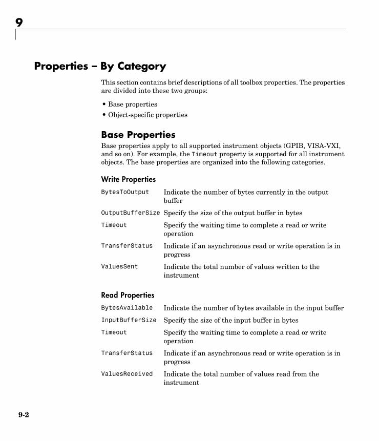
9
9-2
Properties – By CategoryThis section contains brief descriptions of all toolbox properties. The properties are divided into these two groups:
• Base properties
• Object-specific properties
Base PropertiesBase properties apply to all supported instrument objects (GPIB, VISA-VXI, and so on). For example, the Timeout property is supported for all instrument objects. The base properties are organized into the following categories.
Write Properties
Read Properties
BytesToOutput Indicate the number of bytes currently in the output buffer
OutputBufferSize Specify the size of the output buffer in bytes
Timeout Specify the waiting time to complete a read or write operation
TransferStatus Indicate if an asynchronous read or write operation is in progress
ValuesSent Indicate the total number of values written to the instrument
BytesAvailable Indicate the number of bytes available in the input buffer
InputBufferSize Specify the size of the input buffer in bytes
Timeout Specify the waiting time to complete a read or write operation
TransferStatus Indicate if an asynchronous read or write operation is in progress
ValuesReceived Indicate the total number of values read from the instrument
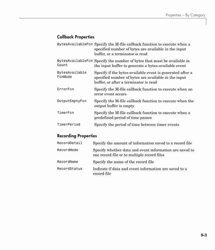
Properties – By Category
9-3
Callback Properties
Recording Properties
BytesAvailableFcn Specify the M-file callback function to execute when a specified number of bytes are available in the input buffer, or a terminator is read
BytesAvailableFcnCount
Specify the number of bytes that must be available in the input buffer to generate a bytes-available event
BytesAvailableFcnMode
Specify if the bytes-available event is generated after a specified number of bytes are available in the input buffer, or after a terminator is read
ErrorFcn Specify the M-file callback function to execute when an error event occurs
OutputEmptyFcn Specify the M-file callback function to execute when the output buffer is empty
TimerFcn Specify the M-file callback function to execute when a predefined period of time passes
TimerPeriod Specify the period of time between timer events
RecordDetail Specify the amount of information saved to a record file
RecordMode Specify whether data and event information are saved to one record file or to multiple record files
RecordName Specify the name of the record file
RecordStatus Indicate if data and event information are saved to a record file

9
9-4
General Purpose Properties
Object-Specific PropertiesObject-specific properties apply only to instrument objects of a given type (GPIB, VISA-VXI, and so on). For example, the BreakInterruptFcn property is supported only for serial port objects. The object-specific properties are organized into the following categories based on instrument object type.
GPIB Properties
ByteOrder Specify the order in which the instrument stores bytes
Name Specify a descriptive name for the instrument object
Status Indicate if the instrument object is connected to the instrument
Tag Specify a label to associate with a instrument object
Type Indicate the object type
UserData Specify data that you want to associate with a instrument object
BoardIndex Specify the index number of the GPIB board
BusManagementStatus
Indicate the state of the GPIB bus management lines
CompareBits Specify the number of bits that must match the EOS character to complete a read operation, or to assert the EOI line
EOIMode Specify if the EOI line is asserted at the end of a write operation
EOSCharCode Specify the EOS character
EOSMode Specify when the EOS character is written or read
HandshakeStatus Indicate the state of the GPIB handshake lines
PrimaryAddress Specify the primary address of the GPIB instrument
SecondaryAddress Specify the secondary address of the GPIB instrument
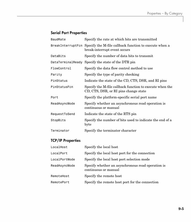
Properties – By Category
9-5
Serial Port Properties
TCP/IP Properties
BaudRate Specify the rate at which bits are transmitted
BreakInterruptFcn Specify the M-file callback function to execute when a break-interrupt event occurs
DataBits Specify the number of data bits to transmit
DataTerminalReady Specify the state of the DTR pin
FlowControl Specify the data flow control method to use
Parity Specify the type of parity checking
PinStatus Indicate the state of the CD, CTS, DSR, and RI pins
PinStatusFcn Specify the M-file callback function to execute when the CD, CTS, DSR, or RI pins change state
Port Specify the platform-specific serial port name
ReadAsyncMode Specify whether an asynchronous read operation is continuous or manual
RequestToSend Indicate the state of the RTS pin
StopBits Specify the number of bits used to indicate the end of a byte
Terminator Specify the terminator character
LocalHost Specify the local host
LocalPort Specify the local host port for the connection
LocalPortMode Specify the local host port selection mode
ReadAsyncMode Specify whether an asynchronous read operation is continuous or manual
RemoteHost Specify the remote host
RemotePort Specify the remote host port for the connection

9
9-6
UDP Properties
VISA-GPIB Properties
Terminator Specify the terminator character
TransferDelay Specify the use of the TCP segment transfer algorithm
DatagramAddress Indicate the IP dotted decimal address of the received datagram sender
DatagramPort Indicate the port number of the datagram sender
DatagramReceivedFcn
Specify the M-file callback function to execute whenever a datagram has been received
DatagramTerminateMode
Configure the terminate read mode when reading datagrams
LocalHost Specify the local host
LocalPort Specify the local host port for the connection
LocalPortMode Specify the local port selection mode
ReadAsyncMode Specify whether an asynchronous read operation is continuous or manual
RemoteHost Specify the remote host
RemotePort Specify the remote host port for the connection
Terminator Specify the terminator character
BoardIndex Specify the index number of the GPIB board
EOIMode Specify if the EOI line is asserted at the end of a write operation
EOSCharCode Specify the EOS character
EOSMode Specify when the EOS character is written or read
PrimaryAddress Specify the primary address of the GPIB instrument
RsrcName Indicate the resource name for a VISA instrument
SecondaryAddress Specify the secondary address of the GPIB instrument

Properties – By Category
9-7
VISA-VXI Properties
ChassisIndex Indicate the index number of the VXI chassis
EOIMode Specify if the EOI line is asserted at the end of a write operation
EOSCharCode Specify the EOS character
EOSMode Specify when the EOS character is written or read
InterruptFcn Specify the M-file callback function to execute when an interrupt event occurs
LogicalAddress Specify the logical address of the VXI instrument
MappedMemoryBase Indicate the base memory address of the mapped memory
MappedMemorySize Indicate the size of the mapped memory for low-level read and write operations
MemoryBase Indicate the base address of the A24 or A32 space
MemoryIncrement Specify if the VXI register offset increments after data is transferred
MemorySize Indicate the size of the memory requested in the A24 or A32 address space
MemorySpace Define the address space used by the instrument
RsrcName Indicate the resource name for a VISA instrument
Slot Indicate the slot location of the VXI instrument
TriggerFcn Specify the M-file callback function to execute when a trigger event occurs
TriggerLine Specify the trigger line on the VXI instrument
TriggerType Specify the trigger type
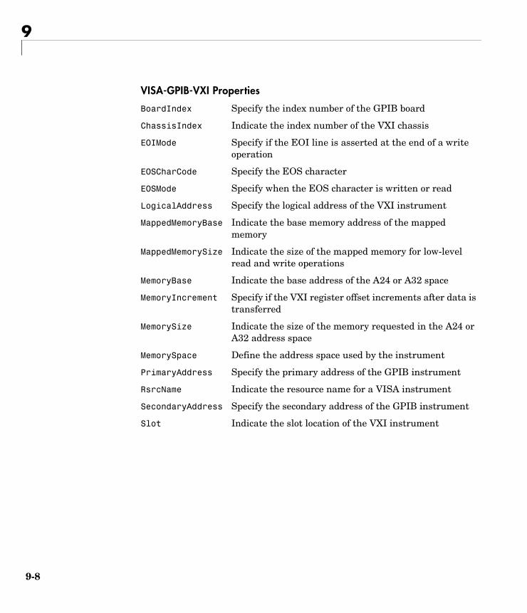
9
9-8
VISA-GPIB-VXI Properties
BoardIndex Specify the index number of the GPIB board
ChassisIndex Indicate the index number of the VXI chassis
EOIMode Specify if the EOI line is asserted at the end of a write operation
EOSCharCode Specify the EOS character
EOSMode Specify when the EOS character is written or read
LogicalAddress Specify the logical address of the VXI instrument
MappedMemoryBase Indicate the base memory address of the mapped memory
MappedMemorySize Indicate the size of the mapped memory for low-level read and write operations
MemoryBase Indicate the base address of the A24 or A32 space
MemoryIncrement Specify if the VXI register offset increments after data is transferred
MemorySize Indicate the size of the memory requested in the A24 or A32 address space
MemorySpace Define the address space used by the instrument
PrimaryAddress Specify the primary address of the GPIB instrument
RsrcName Indicate the resource name for a VISA instrument
SecondaryAddress Specify the secondary address of the GPIB instrument
Slot Indicate the slot location of the VXI instrument
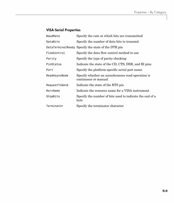
Properties – By Category
9-9
VISA-Serial Properties
BaudRate Specify the rate at which bits are transmitted
DataBits Specify the number of data bits to transmit
DataTerminalReady Specify the state of the DTR pin
FlowControl Specify the data flow control method to use
Parity Specify the type of parity checking
PinStatus Indicate the state of the CD, CTS, DSR, and RI pins
Port Specify the platform-specific serial port name
ReadAsyncMode Specify whether an asynchronous read operation is continuous or manual
RequestToSend Indicate the state of the RTS pin
RsrcName Indicate the resource name for a VISA instrument
StopBits Specify the number of bits used to indicate the end of a byte
Terminator Specify the terminator character

9
9-10
Properties – Alphabetical ListThis section contains detailed descriptions of all toolbox properties. Each property reference page contains some or all of this information:
• The property name
• A description of the property
• The property characteristics, including:
- Usage — the instrument object(s) the property is associated with
- Read only — the condition under which the property is read-only
A property can be read-only always, never, while the instrument object is open, or while the instrument object is recording. You can configure a property value using the set command or dot notation. You can return the current property value using the get command or dot notation.
- Data type — the property data type
This is the data type you use when specifying a property value
• Valid property values including the default value
When property values are given by a predefined list, the default value is usually indicated by {} (curly braces).
• An example using the property
• Related properties and functions
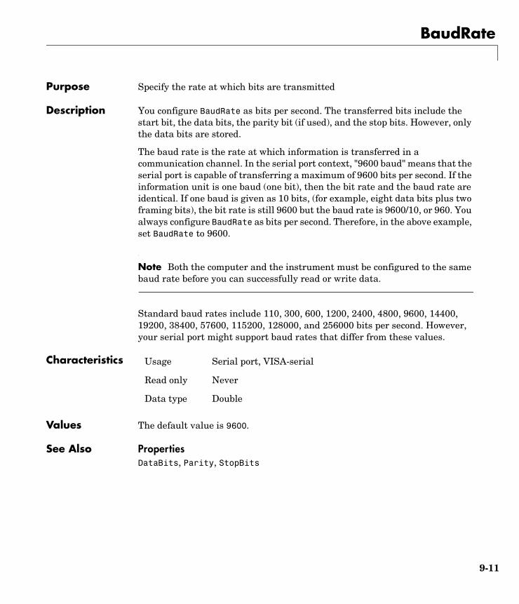
BaudRate
9-11
9BaudRatePurpose Specify the rate at which bits are transmitted
Description You configure BaudRate as bits per second. The transferred bits include the start bit, the data bits, the parity bit (if used), and the stop bits. However, only the data bits are stored.
The baud rate is the rate at which information is transferred in a communication channel. In the serial port context, "9600 baud" means that the serial port is capable of transferring a maximum of 9600 bits per second. If the information unit is one baud (one bit), then the bit rate and the baud rate are identical. If one baud is given as 10 bits, (for example, eight data bits plus two framing bits), the bit rate is still 9600 but the baud rate is 9600/10, or 960. You always configure BaudRate as bits per second. Therefore, in the above example, set BaudRate to 9600.
Note Both the computer and the instrument must be configured to the same baud rate before you can successfully read or write data.
Standard baud rates include 110, 300, 600, 1200, 2400, 4800, 9600, 14400, 19200, 38400, 57600, 115200, 128000, and 256000 bits per second. However, your serial port might support baud rates that differ from these values.
Characteristics
Values The default value is 9600.
See Also PropertiesDataBits, Parity, StopBits
Usage Serial port, VISA-serial
Read only Never
Data type Double

BoardIndex
9-12
9BoardIndexPurpose Specify the index number of the GPIB board
Description You configure BoardIndex to be the index number of the GPIB board associated with your instrument. When you create a GPIB or VISA-GPIB object, BoardIndex is automatically assigned the value specified in the gpib or visa function.
For GPIB objects, the Name property is automatically updated to reflect the BoardIndex value. For VISA-GPIB objects, the Name and RsrcName properties are automatically updated to reflect the BoardIndex value.
You can configure BoardIndex only when the object is disconnected from the instrument. You disconnect a connected object with the fclose function. A disconnected object has a Status property value of closed.
Characteristics
Values The value is defined after the instrument object is created.
Example Suppose you create a VISA-GPIB object associated with board 4, primary address 1, and secondary address 8.
vg = visa('agilent','GPIB4::1::8::INSTR');
The BoardIndex, Name, and RsrcName properties reflect the GPIB board index number.
get(vg,{'BoardIndex','Name','RsrcName'})ans = [4] 'VISA-GPIB4-1-8' 'GPIB4::1::8::INSTR'
See Also Functionsfclose, gpib, visa
PropertiesName, RsrcName, Status
Usage GPIB, VISA-GPIB, VISA-GPIB-VXI
Read only While open (GPIB, VISA-GPIB), always (VISA-GPIB-VXI)
Data type double
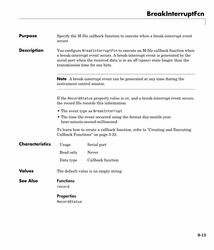
BreakInterruptFcn
9-13
9BreakInterruptFcnPurpose Specify the M-file callback function to execute when a break-interrupt event occurs
Description You configure BreakInterruptFcn to execute an M-file callback function when a break-interrupt event occurs. A break-interrupt event is generated by the serial port when the received data is in an off (space) state longer than the transmission time for one byte.
Note A break-interrupt event can be generated at any time during the instrument control session.
If the RecordStatus property value is on, and a break-interrupt event occurs, the record file records this information:
• The event type as BreakInterrupt
• The time the event occurred using the format day-month-year hour:minute:second:millisecond
To learn how to create a callback function, refer to “Creating and Executing Callback Functions” on page 3-33.
Characteristics
Values The default value is an empty string.
See Also Functionsrecord
PropertiesRecordStatus
Usage Serial port
Read only Never
Data type Callback function
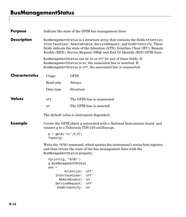
BusManagementStatus
9-14
9BusManagementStatusPurpose Indicate the state of the GPIB bus management lines
Description BusManagementStatus is a structure array that contains the fields Attention, InterfaceClear, RemoteEnable, ServiceRequest, and EndOrIdentify. These fields indicate the state of the Attention (ATN), Interface Clear (IFC), Remote Enable (REN), Service Request (SRQ) and End Or Identify (EOI) GPIB lines.
BusManagementStatus can be on or off for any of these fields. If BusManagementStatus is on, the associated line is asserted. If BusManagementStatus is off, the associated line is unasserted.
Characteristics
Values
The default value is instrument dependent.
Example Create the GPIB object g associated with a National Instruments board, and connect g to a Tektronix TDS 210 oscilloscope.
g = gpib('ni',0,0);fopen(g)
Write the *STB? command, which queries the instrument’s status byte register, and then return the state of the bus management lines with the BusManagementStatus property.
fprintf(g,'*STB?')g.BusManagementStatusans = Attention: 'off' InterfaceClear: 'off' RemoteEnable: 'on' ServiceRequest: 'off' EndOrIdentify: 'on'
Usage GPIB
Read only Always
Data type Structure
off The GPIB line is unasserted
on The GPIB line is asserted

BusManagementStatus
9-15
REN is asserted because the system controller placed the scope in the remote enable mode, while EOI is asserted to mark the end of the command.
Now read the result of the *STB? command, and return the state of the bus management lines.
out = fscanf(g)out =0g.busmanagementstatusans = Attention: 'on' InterfaceClear: 'off' RemoteEnable: 'on' ServiceRequest: 'off' EndOrIdentify: 'off'
ATN is asserted because a multiline response was read from the scope.
fclose(g)delete(g)clear g
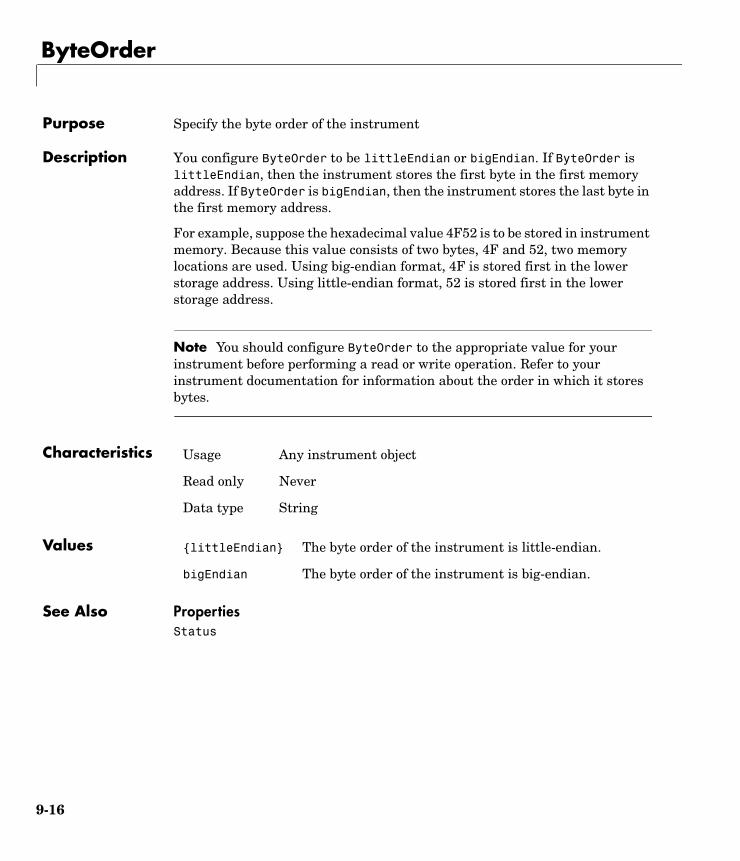
ByteOrder
9-16
9ByteOrderPurpose Specify the byte order of the instrument
Description You configure ByteOrder to be littleEndian or bigEndian. If ByteOrder is littleEndian, then the instrument stores the first byte in the first memory address. If ByteOrder is bigEndian, then the instrument stores the last byte in the first memory address.
For example, suppose the hexadecimal value 4F52 is to be stored in instrument memory. Because this value consists of two bytes, 4F and 52, two memory locations are used. Using big-endian format, 4F is stored first in the lower storage address. Using little-endian format, 52 is stored first in the lower storage address.
Note You should configure ByteOrder to the appropriate value for your instrument before performing a read or write operation. Refer to your instrument documentation for information about the order in which it stores bytes.
Characteristics
Values
See Also PropertiesStatus
Usage Any instrument object
Read only Never
Data type String
{littleEndian} The byte order of the instrument is little-endian.
bigEndian The byte order of the instrument is big-endian.
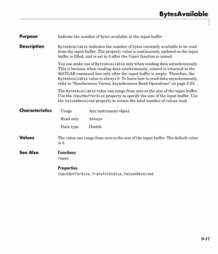
BytesAvailable
9-17
9BytesAvailablePurpose Indicate the number of bytes available in the input buffer
Description BytesAvailable indicates the number of bytes currently available to be read from the input buffer. The property value is continuously updated as the input buffer is filled, and is set to 0 after the fopen function is issued.
You can make use of BytesAvailable only when reading data asynchronously. This is because when reading data synchronously, control is returned to the MATLAB command line only after the input buffer is empty. Therefore, the BytesAvailable value is always 0. To learn how to read data asynchronously, refer to “Synchronous Versus Asynchronous Read Operations” on page 2-23.
The BytesAvailable value can range from zero to the size of the input buffer. Use the InputBufferSize property to specify the size of the input buffer. Use the ValuesReceived property to return the total number of values read.
Characteristics
Values The value can range from zero to the size of the input buffer. The default value is 0.
See Also Functionsfopen
PropertiesInputBufferSize, TransferStatus, ValuesReceived
Usage Any instrument object
Read only Always
Data type Double
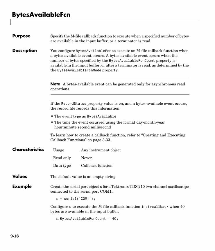
BytesAvailableFcn
9-18
9BytesAvailableFcnPurpose Specify the M-file callback function to execute when a specified number of bytes are available in the input buffer, or a terminator is read
Description You configure BytesAvailableFcn to execute an M-file callback function when a bytes-available event occurs. A bytes-available event occurs when the number of bytes specified by the BytesAvailableFcnCount property is available in the input buffer, or after a terminator is read, as determined by the the BytesAvailableFcnMode property.
Note A bytes-available event can be generated only for asynchronous read operations.
If the RecordStatus property value is on, and a bytes-available event occurs, the record file records this information:
• The event type as BytesAvailable
• The time the event occurred using the format day-month-year hour:minute:second:millisecond
To learn how to create a callback function, refer to “Creating and Executing Callback Functions” on page 3-33.
Characteristics
Values The default value is an empty string.
Example Create the serial port object s for a Tektronix TDS 210 two-channel oscilloscope connected to the serial port COM1.
s = serial('COM1');
Configure s to execute the M-file callback function instrcallback when 40 bytes are available in the input buffer.
s.BytesAvailableFcnCount = 40;
Usage Any instrument object
Read only Never
Data type Callback function
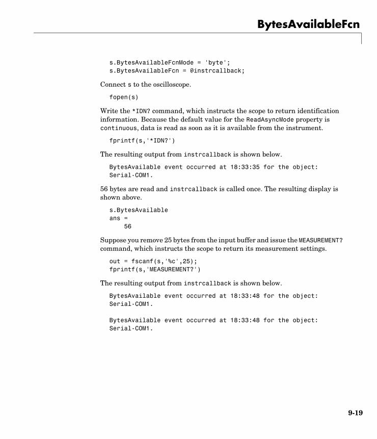
BytesAvailableFcn
9-19
s.BytesAvailableFcnMode = 'byte';s.BytesAvailableFcn = @instrcallback;
Connect s to the oscilloscope.
fopen(s)
Write the *IDN? command, which instructs the scope to return identification information. Because the default value for the ReadAsyncMode property is continuous, data is read as soon as it is available from the instrument.
fprintf(s,'*IDN?')
The resulting output from instrcallback is shown below.
BytesAvailable event occurred at 18:33:35 for the object: Serial-COM1.
56 bytes are read and instrcallback is called once. The resulting display is shown above.
s.BytesAvailableans = 56
Suppose you remove 25 bytes from the input buffer and issue the MEASUREMENT? command, which instructs the scope to return its measurement settings.
out = fscanf(s,'%c',25);fprintf(s,'MEASUREMENT?')
The resulting output from instrcallback is shown below.
BytesAvailable event occurred at 18:33:48 for the object: Serial-COM1.
BytesAvailable event occurred at 18:33:48 for the object: Serial-COM1.

BytesAvailableFcn
9-20
There are now 102 bytes in the input buffer, 31 of which are left over from the *IDN? command. instrcallback is called twice; once when 40 bytes are available and once when 80 bytes are available.
s.BytesAvailableans = 102
See Also Functionsrecord
PropertiesBytesAvailableFcnCount, BytesAvailableFcnMode, EOSCharCode, RecordStatus, Terminator, TransferStatus
BytesAvailableFcnCount
9-21
9BytesAvailableFcnCountPurpose Specify the number of bytes that must be available in the input buffer to generate a bytes-available event
Description You configure BytesAvailableFcnCount to the number of bytes that must be available in the input buffer before a bytes-available event is generated.
Use the BytesAvailableFcnMode property to specify whether the bytes-available event occurs after a certain number of bytes are available or after a terminator is read.
The bytes-available event executes the M-file callback function specified for the BytesAvailableFcn property.
You can configure BytesAvailableFcnCount only when the object is disconnected from the instrument. You disconnect an object with the fclose function. A disconnected object has a Status property value of closed.
Characteristics
Values The default value is 48.
See Also Functionsfclose
PropertiesBytesAvailableFcn, BytesAvailableFcnMode, EOSCharCode, Status, Terminator
Usage Any instrument object
Read only While open
Data type Double
BytesAvailableFcnMode
9-22
9BytesAvailableFcnModePurpose Specify if the bytes-available event is generated after a specified number of bytes are available in the input buffer, or after a terminator is read
Description For serial port, TCP/IP, UDP, or VISA-serial objects, you can configure BytesAvailableFcnMode to be terminator or byte. For all other instrument objects, you can configure BytesAvailableFcnMode to be eosCharCode or byte.
If BytesAvailableFcnMode is terminator, a bytes-available event occurs when the terminator specified by the Terminator property is read. If BytesAvailableFcnMode is eosCharCode, a bytes-available event occurs when the End-Of-String character specified by the EOSCharCode property is read. If BytesAvailableFcnMode is byte, a bytes-available event occurs when the number of bytes specified by the BytesAvailableFcnCount property is available.
The bytes-available event executes the M-file callback function specified for the BytesAvailableFcn property.
You can configure BytesAvailableFcnMode only when the object is disconnected from the instrument. You disconnect an object with the fclose function. A disconnected object has a Status property value of closed.
Characteristics
Values Serial, TCP/IP, UDP, and VISA-serial
Usage Any instrument object
Read only While open
Data type String
{terminator} A bytes-available event is generated when the terminator is reached.
byte A bytes-available event is generated when the specified number of bytes available.
BytesAvailableFcnMode
9-23
GPIB, VISA-GPIB, VISA-VXI, and VISA-GPIB-VXI
See Also Functionsfclose
PropertiesBytesAvailableFcn, BytesAvailableFcnCount, EOSCharCode, Status, Terminator
{eosCharCode} A bytes-available event is generated when the EOS (End-Of-String) character is reached.
byte A bytes-available event is generated when the specified number of bytes available.
BytesToOutput
9-24
9BytesToOutputPurpose Indicate the number of bytes currently in the output buffer
Description BytesToOutput indicates the number of bytes currently in the output buffer waiting to be written to the instrument. The property value is continuously updated as the output buffer is filled and emptied, and is set to 0 after the fopen function is issued.
You can make use of BytesToOutput only when writing data asynchronously. This is because when writing data synchronously, control is returned to the MATLAB command line only after the output buffer is empty. Therefore, the BytesToOutput value is always 0. To learn how to write data asynchronously, Refer to “Synchronous Versus Asynchronous Write Operations” on page 2-17.
Use the ValuesSent property to return the total number of values written to the instrument.
Note If you attempt to write out more data than can fit in the output buffer, then an error is returned and BytesToOutput is 0. You specify the size of the output buffer with the OutputBufferSize property.
Characteristics
Values The default value is 0.
See Also Functionsfopen
PropertiesOutputBufferSize, TransferStatus, ValuesSent
Usage Any instrument object
Read only Always
Data type Double
ChassisIndex
9-25
9ChassisIndexPurpose Specify the index number of the VXI chassis
Description You configure ChassisIndex to be the index number of the VXI chassis associated with your instrument.
When you create a VISA-VXI or VISA-GPIB-VXI object, ChassisIndex is automatically assigned the value specified in the visa function. For both object types, the Name and RsrcName properties are automatically updated to reflect the ChassisIndex value.
You can configure ChassisIndex only when the object is disconnected from the instrument. You disconnect a connected object with the fclose function. A disconnected object has a Status property value of closed.
Characteristics
Values The value is defined after the instrument object is created.
Example Suppose you create a VISA-GPIB-VXI object associated with chassis 0 and logical address 32.
v = visa('agilent','GPIB-VXI0::32::INSTR');
The ChassisIndex, Name, and RsrcName properties reflect the VXI chassis index number.
get(v,{'ChassisIndex','Name','RsrcName'})ans = [0] 'VISA-GPIB-VXI0-32' 'GPIB-VXI0::32::INSTR'
See Also Functionsfclose, visa
PropertiesName, RsrcName, Status
Usage VISA-VXI, VISA-GPIB-VXI
Read only While open
Data type double
CompareBits
9-26
9CompareBitsPurpose Specify the number of bits that must match the EOS character to complete a read operation, or to assert the EOI line
Description You can configure CompareBits to be 7 or 8. If CompareBits is 7, the read operation completes when a byte that matches the low seven bits of the End-Of-String (EOS) character is received. The End Or Identify (EOI) line is asserted when a byte that matches the low seven bits of the EOS character is written. If CompareBits is 8, the read operation completes when a byte that matches all eight bits of the EOS character is received. The EOI line is asserted when a byte that matches all eight bits of the EOS character is written.
You can specify the EOS character with the EOSCharCode property. You can specify when the EOS character is used (read operation, write operation, or both) with the EOSMode property.
Characteristics
Values
See Also PropertiesEOSCharCode, EOSMode
Usage GPIB
Read only Never
Data type Double
{8} Compare all eight EOS bits.
7 Compare the lower seven EOS bits.
DataBits
9-27
9DataBitsPurpose Specify the number of data bits to transmit
Description You can configure DataBits to be 5, 6, 7, or 8. Data is transmitted as a series of five, six, seven, or eight bits with the least significant bit sent first. At least seven data bits are required to transmit ASCII characters. Eight bits are required to transmit binary data. Five and six bit data formats are used for specialized communication equipment.
Note Both the computer and the instrument must be configured to transmit the same number of data bits.
In addition to the data bits, the serial data format consists of a start bit, one or two stop bits, and possibly a parity bit. You specify the number of stop bits with the StopBits property, and the type of parity checking with the Parity property.
Characteristics
Values DataBits can be 5, 6, 7, or 8. The default value is 8.
See Also PropertiesParity, StopBits
Usage Serial port, VISA-serial
Read only Never
Data type Double

DatagramAddress
9-28
9DatagramAddressPurpose Indicate the IP dotted decimal address of the received datagram sender
Description DatagramAddress is the datagram sender IP address of the next datagram to be read from the input buffer. An example of an IP dotted decimal address string is 144.212.100.10.
When you read a datagram from the input buffer, DatagramAddress is updated.
Characteristics
Values The default value is ''.
See Also Functionsudp
PropertiesDatagramPort, RemotePort
Usage UDP
Read only Always
Data type String
DatagramPort
9-29
9DatagramPortPurpose Indicate the port number of the datagram sender
Description DatagramPort is the port number of the datagram to be read next from the input buffer. When you read a datagram from the input buffer, DatagramPort is updated.
Characteristics
Values The default value is [].
See Also Functionsudp
PropertiesDatagramAddress
Usage UDP
Read only Never
Data type Double
DatagramReceivedFcn
9-30
9DatagramReceivedFcnPurpose Specify the M-file callback function to execute whenever a datagram has been received
Description You configure DatagramReceivedFcn to execute an M-file callback function when a datagram has been received. The callback executes when a complete datagram is received in the input buffer.
Note A datagram-received event can be generated at any time during the instrument control session.
If the RecordStatus property value is on, and a datagram-received event occurs, the record file records this information:
• The event type as DatagramReceived
• The time the event occurred using the format day-month-year hour:minute:second:millisecond
To learn how to create a callback function, refer to “Creating and Executing Callback Functions” on page 3-33
Characteristics
Values The default value is ''.
See Also Functionsreadasync, udp
PropertiesDatagramAddress, DatagramPort, ReadAsyncMode
Usage UDP
Read only Never
Data type Callback
DatagramTerminateMode
9-31
9DatagramTerminateModePurpose Configure the terminate read mode when reading datagrams
Description DatagramTerminateMode defines how fread and fscanf read operations terminate. You can configure DatagramTerminateMode to be on or off.
If DatagramTerminateMode is on, the read operation terminates when a datagram is read. When DatagramTerminateMode is off, fread and fscanf read across datagram boundaries.
Characteristics
Values
See Also Functionsfread, fscanf, udp
Usage UDP
Read only Never
Data type String
{on} The read operation terminates when a datagram is read.
off The read operation spans datagram boundaries.

DataTerminalReady
9-32
9DataTerminalReadyPurpose Specify the state of the DTR pin
Description You can configure DataTerminalReady to be on or off. If DataTerminalReady is on, the Data Terminal Ready (DTR) pin is asserted. If DataTerminalReady is off, the DTR pin is unasserted.
In normal usage, the DTR and Data Set Ready (DSR) pins work together, and are used to signal if instruments are connected and powered. However, there is nothing in the RS-232 standard that states the DTR pin must be used in any specific way. For example, DTR and DSR might be used for handshaking. You should refer to your instrument documentation to determine its specific pin behavior.
You can return the value of the DSR pin with the PinStatus property. Handshaking is described in “The Control Pins” on page 5-8.
Characteristics
Values
See Also PropertiesFlowControl, PinStatus
Usage Serial port, VISA-serial
Read only Never
Data type String
{on} The DTR pin is asserted.
off The DTR pin is unasserted.
EOIMode
9-33
9EOIModePurpose Specify if the EOI line is asserted at the end of a write operation
Description You can configure EOIMode to be on or off. If EOIMode is on, the End Or Identify (EOI) line is asserted at the end of a write operation. If EOIMode is off, the EOI line is not asserted at the end of a write operation. EOIMode applies to both binary and text write operations.
Characteristics
Values
See Also PropertiesBusManagementStatus
Usage GPIB, VISA-GPIB, VISA-VXI, VISA-GPIB-VXI
Read only Never
Data type String
{on} The EOI line is asserted at the end of a write operation.
off The EOI line is not asserted at the end of a write operation.
EOSCharCode
9-34
9EOSCharCodePurpose Specify the EOS character
Description You can configure EOSCharCode to an integer value ranging from 0 to 255, or to the equivalent ASCII character. For example, to configure EOSCharCode to a carriage return, you specify the value to be CR or 13.
EOSCharCode replaces \n wherever it appears in the ASCII command sent to the instrument. Note that %s\n is the default format for the fprintf function.
For many practical applications, you will configure both EOSCharCode and the EOSMode property. EOSMode specifies when the EOS character is used. If EOSMode is write or read&write (writing is enabled), the EOI line is asserted every time the EOSCharCode value is written to the instrument. If EOSMode is read or read&write (reading is enabled), then the read operation might terminate when the EOSCharCode value is detected. For GPIB objects, the CompareBits property specifies the number of bits that must match the EOS character to complete a read or write operation.
To see how EOSCharCode and EOSMode work together, refer to the example given in the EOSMode property description.
Characteristics
Values An integer value ranging from 0 to 255 or the equivalent ASCII character. The default value is LF, which corresponds to a line feed.
See Also Functionsfprintf
PropertiesCompareBits, EOSMode
Usage GPIB, VISA-GPIB, VISA-VXI, VISA-GPIB-VXI
Read only Never
Data type ASCII value
EOSMode
9-35
9EOSModePurpose Specify when the EOS character is written or read
Description For GPIB, VISA-GPIB, VISA-VXI, and VISA-GPIB-VXI objects, you can configure EOSMode to be none, read, write, or read&write.
If EOSMode is none, the End-Of-String (EOS) character is ignored. If EOSMode is read, the EOS character is used to terminate a read operation. If EOSMode is write, the EOS character is appended to the ASCII command being written whenever \n is encountered. When the EOS character is written to the instrument, the End Or Identify (EOI) line is asserted. If EOSMode is read&write, the EOS character is used in both read and write operations.
The EOS character is specified by the EOSCharCode property. For GPIB objects, the CompareBits property specifies the number of bits that must match the EOS character to complete a read operation, or to assert the EOI line.
Rules for Completing a Read OperationFor any EOSMode value, the read operation completes when
• The EOI line is asserted.
• Specified number of values is read.
• A timeout occurs.
Additionally, if EOSMode is read or read&write (reading is enabled), then the read operation can complete when the EOSCharCode property value is detected.
Rules for Completing a Write OperationRegardless of the EOSMode value, a write operation completes when
• The specified number of values is written.
• A timeout occurs.
Additionally, if EOSMode is write or read&write, the EOI line is asserted each time the EOSCharCode property value is written to the instrument.
Characteristics Usage GPIB, VISA-GPIB, VISA-VXI, VISA-GPIB-VXI
Read only Never
Data type String
EOSMode
9-36
Values
Example Suppose you input a nominal voltage signal of 2.0 volts into a function generator, and read back the voltage value using fscanf.
g = gpib('ni',0,1); fopen(g) fprintf(g,'Volt?') out = fscanf(g) out = +2.00000E+00
The EOSMode and EOSCharCode properties are configured to terminate the read operation when an E character is encountered.
set(g,'EOSMode','read')set(g,'EOSCharCode','E') fprintf(g,'Volt?')out = fscanf(g)out = +2.00000
See Also PropertiesCompareBits, EOIMode, EOSCharCode
{none} The EOS character is ignored.
read The EOS character is used for each read operation.
write The EOS character is used for each write operation.
read&write The EOS character is used for each read and write operation.
ErrorFcn
9-37
9ErrorFcnPurpose Specify the M-file callback function to execute when an error event occurs
Description You configure ErrorFcn to execute an M-file callback function when an error event occurs.
Note An error event is generated only for asynchronous read and write operations.
An error event is generated when a timeout occurs. A timeout occurs if a read or write operation does not successfully complete within the time specified by the Timeout property. An error event is not generated for configuration errors such as setting an invalid property value.
If the RecordStatus property value is on, and an error event occurs, the record file records this information:
• The event type as Error
• The error message
• The time the event occurred using the format day-month-year hour:minute:second:millisecond
To learn how to create a callback function, refer to “Creating and Executing Callback Functions” on page 3-33.
Characteristics
Values The default value is an empty string.
See Also Functionsrecord
PropertiesRecordStatus, Timeout
Usage Any instrument object
Read only Never
Data type Callback function

FlowControl
9-38
9FlowControlPurpose Specify the data flow control method to use
Description You can configure FlowControl to be none, hardware, or software. If FlowControl is none, then data flow control (handshaking) is not used. If FlowControl is hardware, then hardware handshaking is used to control data flow. If FlowControl is software, then software handshaking is used to control data flow.
Hardware handshaking typically utilizes the Request to Send (RTS) and Clear to Send (CTS) pins to control data flow. Software handshaking uses control characters (Xon and Xoff) to control data flow. To learn more about hardware and software handshaking, refer to “Using Control Pins” on page 5-29.
You can return the value of the CTS pin with the PinStatus property. You can specify the value of the RTS pin with the RequestToSend property. However, if FlowControl is hardware, and you specify a value for RequestToSend, then that value might not be honored.
Note Although you might be able to configure your instrument for both hardware handshaking and software handshaking at the same time, the toolbox does not support this behavior.
Characteristics
Values
See Also PropertiesPinStatus, RequestToSend
Usage Serial port, VISA-serial
Read only Never
Data type String
{none} No flow control is used.
hardware Hardware flow control is used.
software Software flow control is used.
HandshakeStatus
9-39
9HandshakeStatusPurpose Indicate the state of the GPIB handshake lines
Description HandshakeStatus is a structure array that contains the fields DataValid, NotDataAccepted, and NotReadyForData. These fields indicate the state of the Data Valid (DAV), Not Data Accepted (NDAC) and Not Ready For Data (NRFD) GPIB lines, respectively.
HandshakeStatus can be on or off for any of these fields. A value of on indicates the associated line is asserted. A value of off indicates the associated line is unasserted.
Characteristics
Values
The default value is instrument dependent.
Usage GPIB
Read only Never
Data type Structure
on The associated handshake line is asserted
off The associated handshake line is unasserted
InputBufferSize
9-40
9InputBufferSizePurpose Specify the size of the input buffer in bytes
Description You configure InputBufferSize as the total number of bytes that can be stored in the software input buffer during a read operation.
A read operation is terminated if the amount of data stored in the input buffer equals the InputBufferSize value. You can read text data with the fgetl, fgets, or fscanf functions. You can read binary data with the fread function.
You can configure InputBufferSize only when the instrument object is disconnected from the instrument. You disconnect an object with the fclose function. A disconnected object has a Status property value of closed.
If you configure InputBufferSize while there is data in the input buffer, then that data is flushed.
Characteristics
Values The default value is 512.
See Also Functionsfclose, fgetl, fgets, fopen, fread, fscanf
PropertiesStatus
Usage Any instrument object
Read only While open
Data type Double
InterruptFcn
9-41
9InterruptFcnPurpose Specify the M-file callback function to execute when an interrupt event occurs
Description You configure InterruptFcn to execute an M-file callback function when an interrupt event occurs. An interrupt event is generated when a VXI bus signal or a VXI bus interrupt is received from the instrument.
Note An interrupt event can be generated at any time during the instrument control session.
If the RecordStatus property value is on, and an interrupt event occurs, the record file records
• The event type as Interrupt
• The time the event occurred using the format day-month-year hour:minute:second:millisecond
Characteristics
Values The default value is an empty string.
See Also Functionsrecord
PropertiesRecordStatus
Usage VISA-VXI
Read only Never
Data type String
LocalHost
9-42
9LocalHostPurpose Specify the local host
Description LocalHost specifies the local host name or the IP dotted decimal address. An example dotted decimal address is 144.212.100.10. If you have only one address or you do not specify this property, the object uses the default IP address when you connect to the hardware with the fopen function.
You can configure LocalHost only when the object is disconnected from the hardware. You disconnect a connected object with the fclose function. A disconnected object has a Status property value of closed.
Characteristics
Values The default value is ''.
See Also Functionsfclose, fopen, tcpip, udp
PropertiesLocalPort, RemoteHost, Status
Usage TCP/IP, UDP
Read only While open
Data type String
LocalPort
9-43
9LocalPortPurpose Specify the local host port for the connection
Description You configure LocalPort to be the port value of the local host. The default value is [].
If LocalPortMode is set to auto or if LocalPort is [], the property is assigned any free port when you connect the object to the hardware with the fopen function. If LocalPortMode is set to manual, the specified LocalPort value is used when you issue fopen. If you explicitly configure LocalPort, LocalPortMode is automatically set to manual.
You can configure LocalPort only when the object is disconnected from the hardware. You disconnect a connected object with the fclose function. A disconnected object has a Status property value of closed.
Characteristics
Values The default value is [].
See Also Functionsfclose, fopen, tcpip, udp
PropertiesLocalHost, LocalPortMode, Status
Usage TCP/IP, UDP
Read only While open
Data type Double
LocalPortMode
9-44
9LocalPortModePurpose Specify the local host port selection mode
Description LocalPortMode specifies the selection mode for the LocalPort property when you connect a TCP/IP or UDP object.
If LocalPortMode is set to auto, MATLAB uses any free local port. If LocalPortMode is set to manual, the specified LocalPort value is used when you issue the fopen function. If you explicitly specify a value for LocalPort, LocalPortMode is automatically set to manual.
Characteristics
Values
See Also Functionsfclose, fopen, tcpip, udp
PropertiesLocalHost, LocalPort, Status
Usage TCP/IP, UDP
Read only While open
Data type String
{auto} Use any free local port.
manual Use the specified local port value.

LogicalAddress
9-45
9LogicalAddressPurpose Specify the logical address of the VXI instrument
Description For VISA-VXI and VISA-GPIB-VXI objects, you configure LogicalAddress to be the logical address of the VXI instrument. You must include the logical address as part of the resource name during object creation using the visa function.
The Name and RsrcName properties are automatically updated to reflect the LogicalAddress value.
You can configure LogicalAddress only when the object is disconnected from the instrument. You disconnect a connected object with the fclose function. A disconnected object has a Status property value of closed.
Characteristics
Values The value is defined when the instrument object is created.
Example This example creates a VISA-VXI object associated with chassis 4 and logical address 1, and then returns the logical address.
vv = visa('agilent','VXI4::1::INSTR');vv.LogicalAddressans = 1
See Also Functionsfclose, visa
PropertiesName, RsrcName, Status
Usage VISA-VXI, VISA-GPIB-VXI
Read only While open
Data type Double
MappedMemoryBase
9-46
9MappedMemoryBasePurpose Indicate the base memory address of the mapped memory
Description MappedMemoryBase is the base address of the mapped memory used for low level read and write operations.
The memory address is returned as a string representing a hexadecimal value. For example, if the mapped memory base is 200000, then MappedMemoryBase returns 200000H. If no memory is mapped, MappedMemoryBase is 0H.
Use the memmap function to map the specified amount of memory in the specified address space (A16, A24, or A32) with the specified offset. Use the memunmap function to unmap the memory space.
Characteristics
Values The default value is 0H.
Example Create the VISA-VXI object vv associated with a VXI chassis with index 0, and an Agilent E1432A digitizer with logical address 130.
vv = visa('agilent','VXI0::130::INSTR');fopen(vv)
Map 16 bytes in the A16 address space with no offset, and then return the base address of the mapped memory.
memmap(vv,'A16',0,16)vv.MappedMemoryBaseans = 16737610H
See Also Functionsmemmap, memunmap
PropertiesMappedMemorySize
Usage VISA-VXI, VISA-GPIB-VXI
Read only Always
Data type String
MappedMemorySize
9-47
9MappedMemorySizePurpose Indicate the size of the mapped memory for low-level read and write operations
Description MappedMemorySize indicates the amount of memory mapped for low-level read and write operations.
Use the memmap function to map the specified amount of memory in the specified address space (A16, A24, or A32) with the specified offset. Use the memunmap function to unmap the memory space.
Characteristics
Values The default value is 0.
Example Create the VISA-VXI object vv associated with a VXI chassis with index 0, and an Agilent E1432A digitizer with logical address 130.
vv = visa('agilent','VXI0::130::INSTR');fopen(vv)
Map 16 bytes in the A16 address space with no offset, and then return the size of the mapped memory.
memmap(vv,'A16',0,16)vv.MappedMemorySizeans = 16
See Also Functionsmemmap, memunmap
PropertiesMappedMemoryBase
Usage VISA-VXI, VISA-GPIB-VXI
Read only Always
Data type Double
MemoryBase
9-48
9MemoryBasePurpose Indicate the base address of the A24 or A32 space
Description MemoryBase indicates the base address of the A24 or A32 space. The value is returned as a string representing a hexadecimal value.
All VXI instruments have an A16 address space that is 16 bits wide. There are also 24- and 32-bit wide address spaces known as A24 and A32. Some instruments require the additional memory associated with the A24 or A32 address space when the 64 bytes of A16 space are insufficient for performing necessary functions. A bit in the A16 address space is set allowing the instrument to recognize commands to its A24 or A32 space.
An instrument cannot use both the A24 and A32 address space. The address space is given by the MemorySpace property. If MemorySpace is A16, then MemoryBase is 0H.
Characteristics
Values The default value is 0H.
Example Create the VISA-VXI object vv associated with a VXI chassis with index 0, and an Agilent E1432A digitizer with logical address 130.
vv = visa('agilent','VXI0::130::INSTR');fopen(vv)
The MemorySpace property indicates that the A24 memory space is supported.
vv.MemorySpaceans =A16/A24
Usage VISA-VXI, VISA-GPIB-VXI
Read only Always
Data type String

MemoryBase
9-49
The base address of the A24 space is
vv.MemoryBaseans ='200000H'
See Also PropertiesMemorySpace
MemoryIncrement
9-50
9MemoryIncrementPurpose Specify if the VXI register offset increments after data is transferred
Description You can configure MemoryIncrement to be block or FIFO. If MemoryIncrement is block, the memread and memwrite functions increment the offset after every read and write operation, and data is transferred from or to consecutive memory elements. If MemoryIncrement is FIFO, the memread and memwrite functions do not increment the VXI register offset, and data is always read from or written to the same memory element.
Characteristics
Values
Example Create the VISA-VXI object v associated with a VXI chassis with index 0, and an instrument with logical address 8.
v = visa('ni','VXI0::8::INSTR');fopen(v)
Configure the hardware for a FIFO read and write operation.
set(v,'MemoryIncrement','FIFO')
Write two values to the VXI register starting at offset 16. Because MemoryIncrement is FIFO, the VXI register offset does not change and both values are written to offset 16.
memwrite(v,[1984 2000],16,'uint32','A16')
Read the value at offset 16. The value returned is the second value written with the memwrite function.
memread(v,16,'uint32')ans =2000
Usage VISA-VXI, VISA-GPIB-VXI
Read only Never
Data type String
{block} Increment the VXI register offset.
FIFO Do not increment the VXI register offset.

MemoryIncrement
9-51
Read two values starting at offset 16. Note that both values are read at offset 16.
memread(v,16,'uint32','A16',2);ans =20002000
Configure the hardware for a block read and write operation.
set(v,'MemoryIncrement','block')
Write two values to the VXI register starting at offset 16. The first value is written to offset 16 and the second value is written to offset 20 because a uint32 value consists of four bytes.
memwrite(v,[1984 2000],16,'uint32','A16')
Read the value at offset 16. The value returned is the first value written with the memwrite function.
memread(v,16,'uint32')ans =1984
Read two values starting at offset 16. The first value is read at offset 16 and the second value is read at offset 20.
memread(v,16,'uint32','A16',2);ans =19842000
See Also Functionsmempeek, mempoke, memread, memwrite
MemorySize
9-52
9MemorySizePurpose Indicate the size of the memory requested in the A24 or A32 address space
Description MemorySize indicates the size of the memory requested by the instrument in the A24 or A32 address space.
Some instruments use the A24 or A32 address space when the 64 bytes of A16 space are not enough for performing necessary functions. An instrument cannot use both the A24 and A32 address space. The address space is given by the MemorySpace property. If MemorySpace is A16, then MemorySize is 0.
Characteristics
Values The default value is 0.
Example Create the VISA-VXI object vv associated with a VXI chassis with index 0, and an Agilent E1432A digitizer with logical address 130.
vv = visa('agilent','VXI0::130::INSTR');fopen(vv)
The MemorySpace property indicates that the A24 memory space is supported.
vv.MemorySpaceans =A16/A24
The size of the A24 space is
vv.MemorySizeans =262144
See Also PropertiesMemorySpace
Usage VISA-VXI, VISA-GPIB-VXI
Read only Always
Data type Double
MemorySpace
9-53
9MemorySpacePurpose Indicate the address space used by the instrument
Description MemorySpace indicates the address space requested by the instrument. MemorySpace can be A16, A16/A24, or A16/A32. If MemorySpace is A16, the instrument uses only the A16 address space. If MemorySpace is A16/A24, the instrument uses the A16 and A24 address space. If MemorySpace is A16/A32, the instrument uses the A16 and A32 address space.
All VXI instruments have an A16 address space that is 16 bits wide. There are also 24- and 32-bit wide address spaces known as A24 and A32, respectively. Some instruments use this memory when the 64 bytes of A16 space are not enough for performing necessary functions. An instrument cannot use both the A24 and A32 address space.
The size of the memory is given by the MemorySize property. The base address of the memory is given by the MemoryBase property.
Characteristics
Values
Example Create the VISA-VXI object vv associated with a VXI chassis with index 0, and an Agilent E1432A digitizer with logical address 130.
vv = visa('agilent','VXI0::130::INSTR');fopen(vv)
Return the memory space supported by the instrument.
vv.MemorySpaceans =A16/A24
Usage VISA-VXI, VISA-GPIB-VXI
Read only Always
Data type String
{A16} The instrument uses the A16 address space.
A16/A24 The instrument uses the A16 and A24 address space.
A16/A32 The instrument uses the A16 and A32 address space.

MemorySpace
9-54
This value indicates that the instrument supports A24 memory space in addition to the A16 memory space.
See Also PropertiesMemoryBase, MemorySize
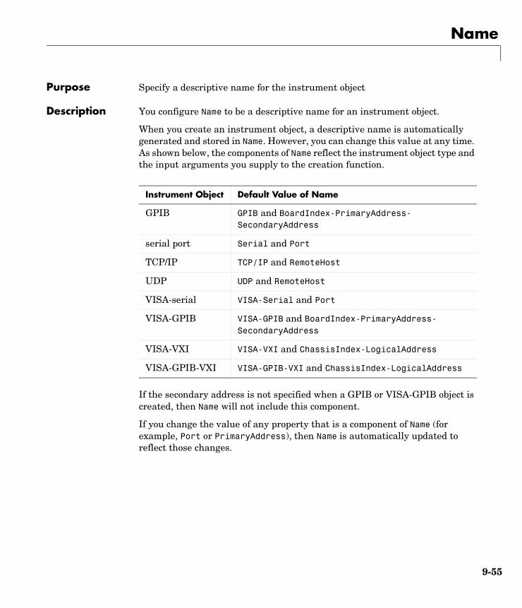
Name
9-55
9NamePurpose Specify a descriptive name for the instrument object
Description You configure Name to be a descriptive name for an instrument object.
When you create an instrument object, a descriptive name is automatically generated and stored in Name. However, you can change this value at any time. As shown below, the components of Name reflect the instrument object type and the input arguments you supply to the creation function.
If the secondary address is not specified when a GPIB or VISA-GPIB object is created, then Name will not include this component.
If you change the value of any property that is a component of Name (for example, Port or PrimaryAddress), then Name is automatically updated to reflect those changes.
Instrument Object Default Value of Name
GPIB GPIB and BoardIndex-PrimaryAddress- SecondaryAddress
serial port Serial and Port
TCP/IP TCP/IP and RemoteHost
UDP UDP and RemoteHost
VISA-serial VISA-Serial and Port
VISA-GPIB VISA-GPIB and BoardIndex-PrimaryAddress- SecondaryAddress
VISA-VXI VISA-VXI and ChassisIndex-LogicalAddress
VISA-GPIB-VXI VISA-GPIB-VXI and ChassisIndex-LogicalAddress
Name
9-56
Characteristics
Values Name is automatically defined at object creation time. The value of Name depends on the specific instrument object you create.
Usage Any instrument object
Read only Never
Data type String
OutputBufferSize
9-57
9OutputBufferSizePurpose Specify the size of the output buffer in bytes
Description You configure OutputBufferSize as the total number of bytes that can be stored in the software output buffer during a write operation.
An error occurs if the output buffer cannot hold all the data to be written. You write text data with the fprintf function. You write binary data with the fwrite function.
You can configure OutputBufferSize only when the instrument object is disconnected from the instrument. You disconnect an object with the fclose function. A disconnected object has a Status property value of closed.
Characteristics
Values The default value is 512.
See Also Functionsfprintf, fwrite
PropertiesStatus
Usage Any instrument object
Read only While open
Data type Double

OutputEmptyFcn
9-58
9OutputEmptyFcnPurpose Specify the M-file callback function to execute when the output buffer is empty
Description You configure OutputEmptyFcn to execute an M-file callback function when an output-empty event occurs. An output-empty event is generated when the last byte is sent from the output buffer to the instrument.
Note An output-empty event can be generated only for asynchronous write operations.
If the RecordStatus property value is on, and an output-empty event occurs, the record file records this information:
• The event type as OutputEmpty
• The time the event occurred using the format day-month-year hour:minute:second:millisecond
To learn how to create a callback function, refer to “Creating and Executing Callback Functions” on page 3-33.
Characteristics
Values The default value is an empty string.
See Also Functionsrecord
PropertiesRecordStatus
Usage Any instrument object
Read only Never
Data type Callback function
Parity
9-59
9ParityPurpose Specify the type of parity checking
Description You can configure Parity to be none, odd, even, mark, or space. If Parity is none, parity checking is not performed and the parity bit is not transmitted. If Parity is odd, the number of mark bits (1’s) in the data is counted, and the parity bit is asserted or unasserted to obtain an odd number of mark bits. If Parity is even, the number of mark bits in the data is counted, and the parity bit is asserted or unasserted to obtain an even number of mark bits. If Parity is mark, the parity bit is asserted. If Parity is space, the parity bit is unasserted.
Parity checking can detect errors of one bit only. An error in two bits might cause the data to have a seemingly valid parity, when in fact it is incorrect. To learn more about parity checking, refer to “The Parity Bit” on page 5-12.
In addition to the parity bit, the serial data format consists of a start bit, between five and eight data bits, and one or two stop bits. You specify the number of data bits with the DataBits property, and the number of stop bits with the StopBits property.
Characteristics
Values
See Also PropertiesDataBits, StopBits
Usage Serial port, VISA-serial
Read only Never
Data type String
{none} No parity checking
odd Odd parity checking
even Even parity checking
mark Mark parity checking
space Space parity checking

PinStatus
9-60
9PinStatusPurpose Indicate the state of the CD, CTS, DSR, and RI pins
Description PinStatus is a structure array that contains the fields CarrierDetect, ClearToSend, DataSetReady and RingIndicator. These fields indicate the state of the Carrier Detect (CD), Clear to Send (CTS), Data Set Ready (DSR) and Ring Indicator (RI) pins, respectively. Refer to “The Control Pins” on page 5-8 to learn more about these pins.
PinStatus can be on or off for any of these fields. A value of on indicates the associated pin is asserted. A value of off indicates the associated pin is unasserted. For serial port objects, a pin status event occurs when any of these pins changes its state. A pin status event executes the M-file specified by PinStatusFcn.
In normal usage, the Data Terminal Ready (DTR) and DSR pins work together, while the Request To Send (RTS) and CTS pins work together. You can specify the state of the DTR pin with the DataTerminalReady property. You can specify the state of the RTS pin with the RequestToSend property.
Refer to “Example: Connecting Two Modems” on page 5-29 for an example that uses PinStatus.
Characteristics
Values
The default value is instrument dependent.
See Also PropertiesDataTerminalReady, PinStatusFcn, RequestToSend
Usage Serial port, VISA-serial
Read only Always
Data type Structure
off The associated pin is asserted
on The associated pin is asserted
PinStatusFcn
9-61
9PinStatusFcnPurpose Specify the M-file callback function to execute when the CD, CTS, DSR, or RI pin changes state
Description You configure PinStatusFcn to execute an M-file callback function when a pin status event occurs. A pin status event occurs when the Carrier Detect (CD), Clear to Send (CTS), Data Set Ready (DSR) or Ring Indicator (RI) pin changes state. A serial port pin changes state when it is asserted or unasserted. Information about the state of these pins is recorded in the PinStatus property.
Note A pin status event can be generated at any time during the instrument control session.
If the RecordStatus property value is on, and a pin status event occurs, the record file records this information:
• The event type as PinStatus
• The pin that changed its state, and pin state as either on or off
• The time the event occurred using the format day-month-year hour:minute:second:millisecond
To learn how to create a callback function, refer to “Creating and Executing Callback Functions” on page 3-33.
Characteristics
Values The default value is an empty string.
See Also Functionsrecord
PropertiesPinStatus, RecordStatus
Usage Serial port
Read only Never
Data type Callback function

Port
9-62
9PortPurpose Specify the platform-specific serial port name
Description You configure Port to be the name of a serial port on your platform. Port specifies the physical port associated with the object and the instrument.
When you create a serial port or VISA-serial object, Port is automatically assigned the port name specified for the serial or visa function.
You can configure Port only when the object is disconnected from the instrument. You disconnect an object with the fclose function. A disconnected object has a Status property value of closed.
Characteristics
Values The value is determined when the instrument object is created.
Example Suppose you create a serial port and VISA-serial object associated with serial port COM1.
s = serial('COM1') vs = visa('ni','ASRL1::INSTR')
The Port property values are given below.
get([s vs],'Port')ans = 'COM1' 'ASRL1'
See Also Functionsfclose, serial, visa
PropertiesName, RsrcName, Status
Usage Serial port, VISA-serial
Read only While open
Data type String
PrimaryAddress
9-63
9PrimaryAddressPurpose Specify the primary address of the GPIB instrument
Description For GPIB and VISA-GPIB objects, you configure PrimaryAddress to be the GPIB primary address associated with your instrument. The primary address can range from 0 to 30, and you must specify it during object creation using the gpib or visa function. For VISA-GPIB-VXI objects, PrimaryAddress is read-only, and the value is returned automatically by the VISA interface after the object is connected to the instrument with the fopen function.
For GPIB and VISA-GPIB objects, the Name property is automatically updated to reflect the PrimaryAddress value. For VISA-GPIB objects, the RsrcName property is automatically updated to reflect the PrimaryAddress value.
You can configure PrimaryAddress only when the GPIB or VISA-GPIB object is disconnected from the instrument. You disconnect a connected object with the fclose function. A disconnected object has a Status property value of closed.
Characteristics
Values PrimaryAddress can range from 0 to 30. The value is determined when the instrument object is created.
Example This example creates a VISA-GPIB object associated with board 0, primary address 1, and secondary address 8, and then returns the primary address.
vg = visa('agilent','GPIB0::1::8::INSTR');vg.PrimaryAddressans = 1
See Also Functionsfclose, gpib, visa
PropertiesName, RsrcName, Status
Usage GPIB, VISA-GPIB, VISA-GPIB-VXI
Read only While open (GPIB, VISA-GPIB), always (VISA-GPIB-VXI)
Data type Double
ReadAsyncMode
9-64
9ReadAsyncModePurpose Specify whether an asynchronous read operation is continuous or manual
Description You can configure ReadAsyncMode to be continuous or manual. If ReadAsyncMode is continuous, the object continuously queries the instrument to determine if data is available to be read. If data is available, it is automatically read and stored in the input buffer. If issued, the readasync function is ignored.
If ReadAsyncMode is manual, the object will not query the instrument to determine if data is available to be read. Instead, you must manually issue the readasync function to perform an asynchronous read operation. Because readasync checks for the terminator, this function can be slow. To increase speed, you should configure ReadAsyncMode to continuous.
Note If the instrument is ready to transmit data, then it will do so regardless of the ReadAsyncMode value. Therefore, if ReadAsyncMode is manual and a read operation is not in progress, then data can be lost. To guarantee that all transmitted data is stored in the input buffer, you should configure ReadAsyncMode to continuous.
You can determine the amount of data available in the input buffer with the BytesAvailable property. For either ReadAsyncMode value, you can bring data into the MATLAB workspace with one of the synchronous read functions such as fscanf, fgetl, fgets, or fread.
Characteristics
Values
Usage Serial port, TCP/IP, UDP, VISA-serial
Read only Never
Data type String
{continuous} Continuously query the instrument to determine if data is available to be read.
manual Manually read data from the instrument using the readasync function.
ReadAsyncMode
9-65
See Also Functionsfgetl, fgets, fread, fscanf, readasync
PropertiesBytesAvailable, InputBufferSize
RecordDetail
9-66
9RecordDetailPurpose Specify the amount of information saved to a record file
Description You can configure RecordDetail to be compact or verbose. If RecordDetail is compact, the number of values written to the instrument, the number of values read from the instrument, the data type of the values, and event information are saved to the record file. If RecordDetail is verbose, the data transferred to and from the instrument is also saved to the record file.
The verbose record file structure is shown in “Example: Recording Information to Disk” on page 7-9.
Characteristics
Values
See Also Functionsrecord
PropertiesRecordMode, RecordName, RecordStatus
Usage Any instrument object
Read only Never
Data type String
{compact} The number of values written to the instrument, the number of values read from the instrument, the data type of the values, and event information are saved to the record file.
verbose The data written to the instrument, and the data read from the instrument are also saved to the record file.
RecordMode
9-67
9RecordModePurpose Specify whether data and event information are saved to one record file or to multiple record files
Description You can configure RecordMode to be overwrite, append, or index. If RecordMode is overwrite, then the record file is overwritten each time recording is initiated. If RecordMode is append, then data is appended to the record file each time recording is initiated. If RecordMode is index, a different record file is created each time recording is initiated, each with an indexed filename.
You can configure RecordMode only when the object is not recording. You terminate recording with the record function. A object that is not recording has a RecordStatus property value of off.
You specify the record filename with the RecordName property. The indexed filename follows a prescribed set of rules. Refer to “Specifying a Filename” on page 7-6 for a description of these rules.
Characteristics
Values
Example Suppose you create the serial port object s associated with the serial port COM1.
s = serial('COM1');fopen(s)
Specify the record filename with the RecordName property, configure RecordMode to index, and initiate recording.
s.RecordName = 'myrecord.txt';
Usage Any instrument object
Read only While recording
Data type String
{overwrite} The record file is overwritten.
append Data is appended to the record file.
index Multiple record files are written, each with an indexed filename.
RecordMode
9-68
s.RecordMode = 'index';record(s)
The record filename is automatically updated with an indexed filename after recording is turned off.
record(s,'off')s.RecordNameans =myrecord01.txt
Disconnect s from the instrument, and remove s from memory and from the MATLAB workspace.
fclose(s)delete(s)clear s
See Also Functionsrecord
PropertiesRecordDetail, RecordName, RecordStatus
RecordName
9-69
9RecordNamePurpose Specify the name of the record file
Description You configure RecordName to be the name of the record file. You can specify any value for RecordName — including a directory path — provided the filename is supported by your operating system.
MATLAB supports any filename supported by your operating system. However, if you access the file through MATLAB, you might need to specify the filename using single quotes. For example, suppose you name the record file my record.txt. To type this file at the MATLAB command line, you must include the name in quotes.
type('my record.txt')
You can specify whether data and event information are saved to one disk file or to multiple disk files with the RecordMode property. If RecordMode is index, then the filename follows a prescribed set of rules. Refer to “Specifying a Filename” on page 7-6 for a description of these rules.
You can configure RecordName only when the object is not recording. You terminate recording with the record function. An object that is not recording has a RecordStatus property value of off.
Characteristics
Values The default record file name is record.txt.
See Also Functionsrecord
PropertiesRecordDetail, RecordMode, RecordStatus
Usage Any instrument object
Read only While recording
Data type String
RecordStatus
9-70
9RecordStatusPurpose Indicate if data and event information are saved to a record file
Description You can configure RecordStatus to be off or on with the record function. If RecordStatus is off, then data and event information are not saved to a record file. If RecordStatus is on, then data and event information are saved to the record file specified by RecordName.
Use the record function to initiate or complete recording. RecordStatus is automatically configured to reflect the recording state.
Characteristics
Values
See Also Functionsrecord
PropertiesRecordDetail, RecordMode, RecordName
Usage Any instrument object
Read only Always
Data type String
{off} Data and event information are not written to a record file
on Data and event information are written to a record file

RemoteHost
9-71
9RemoteHostPurpose Specify the remote host
Description RemoteHost specifies the remote host name or IP dotted decimal address. An example dotted decimal address is 144.212.100.10.
For TCP/IP objects, you can configure RemoteHost only when the object is disconnected from the hardware. You disconnect a connected object with the fclose function. A disconnected object has a Status property value of closed.
For UDP objects, you can configure RemoteHost at any time. If the object is open, a warning is issued if the remote address is invalid.
Characteristics
Values The value is defined when you create the TCP/IP or UDP object.
See Also Functionsfclose, fopen, tcpip, udp
PropertiesLocalHost, RemotePort, Status
Usage TCP/IP, UDP
Read only While open (TCP/IP), Never (UDP)
Data type String

RemotePort
9-72
9RemotePortPurpose Specify the remote host port for the connection
Description You can configure RemotePort to be any port number between 1 and 65535. The default value is 80 for TCP/IP objects and 9090 for UDP objects.
For TCP/IP objects, you can configure RemotePort only when the object is disconnected from the hardware. You disconnect a connected object with the fclose function. A disconnected object has a Status property value of closed.
For UDP objects, you can configure RemotePort at any time.
Characteristics
Values Any port number between 1 and 65535. The default value is 80 for TCP/IP objects and 9090 for UDP objects.
See Also Functionsfclose, fopen, tcpip, udp
PropertiesRemoteHost, LocalPort, Status
Usage TCP/IP, UDP
Read only While open (TCP/IP), Never (UDP)
Data type Double
RequestToSend
9-73
9RequestToSendPurpose Specify the state of the RTS pin
Description You can configure RequestToSend to be on or off. If RequestToSend is on, the Request to Send (RTS) pin is asserted. If RequestToSend is off, the RTS pin is unasserted.
In normal usage, the RTS and Clear to Send (CTS) pins work together, and are used as standard handshaking pins for data transfer. In this case, RTS and CTS are automatically managed by the DTE and DCE. However, there is nothing in the RS-232 standard that states the RTS pin must to be used in any specific way. Therefore, if you manually configure the RequestToSend value, it is probably for nonstandard operations.
If your instrument does not use hardware handshaking in the standard way, and you need to manually configure RequestToSend, then you should configure the FlowControl property to none. Otherwise, the RequestToSend value that you specify might not be honored. Refer to your instrument documentation to determine its specific pin behavior.
You can return the value of the CTS pin with the PinStatus property. Handshaking is described in “The Control Pins” on page 5-8.
Characteristics
Values
See Also PropertiesFlowControl, PinStatus
Usage Serial port, VISA-serial
Read only Never
Data type String
{on} The RTS pin is asserted.
off The RTS pin is unasserted.
RsrcName
9-74
9RsrcNamePurpose Indicate the resource name for a VISA instrument
Description RsrcName indicates the resource name for a VISA instrument. When you create a VISA object, RsrcName is automatically assigned the value specified in the visa function.
The resource name is a symbolic name for the instrument. The resource name you supply to visa depends on the interface and has the format shown below. The components in brackets are optional and have a default value of 0 except port_number, which has a default value of 1.
If you change the BoardIndex, PrimaryAddress, SecondaryAddress, ChassisIndex, LogicalAddress, or Port property values, RsrcName is automatically updated to reflect these changes.
Characteristics
Values The value is defined when the instrument object is created.
Example To create a VISA-GPIB object associated with a GPIB controller with board index 0 and an instrument with primary address 1, you supply the following resource name to the visa function.
vg = visa('ni','GPIB0::1::INSTR');
Interface Resource Name
GPIB GPIB[board]::primary_address::[secondary_address]::INSTR
VXI VXI[chassis]::VXI_logical_address::INSTR
GPIB-VXI GPIB-VXI[chassis]::VXI_logical_address::INSTR
Serial ASRL[port_number]::INSTR
Usage VISA-GPIB, VISA-VXI, VISA-GPIB-VXI, VISA-serial
Read only Always
Data type String
RsrcName
9-75
To create a VISA-VXI object associated with a VXI chassis with index 0 and an instrument with logical address 130, you supply the following resource name to the visa function.
vv = visa('agilent','VXI0::130::INSTR');
To create a VISA-GPIB-VXI object associated with a VXI chassis with index 0 and an instrument with logical address 80, you supply the following resource name to the visa function.
vgv = visa('agilent','GPIB-VXI0::80::INSTR');
To create a VISA-serial object associated with the COM1 serial port, you supply the following resource name to the visa function.
vs = visa('ni','ASRL1::INSTR');
See Also Functionsvisa
PropertiesBoardIndex, ChassisIndex, LogicalAddress, Port, PrimaryAddress, SecondaryAddress
SecondaryAddress
9-76
9SecondaryAddressPurpose Specify the secondary address of the GPIB instrument
Description For GPIB and VISA-GPIB objects, you configure SecondaryAddress to be the GPIB secondary address associated with your instrument. You can initially specify the secondary address during object creation using the gpib or visa function. For VISA-GPIB-VXI objects, SecondaryAddress is read-only, and the value is returned automatically by the VISA interface after the object is connected to the instrument with the fopen function.
For GPIB objects, SecondaryAddress can range from 96 to 126, or it can be 0 indicating that no secondary address is used. For VISA-GPIB objects, SecondaryAddress can range from 0 to 30. If your instrument does not have a secondary address, then SecondaryAddress is 0.
For GPIB and VISA-GPIB objects, the Name property is automatically updated to reflect the SecondaryAddress value. For VISA-GPIB objects, the RsrcName property is automatically updated to reflect the SecondaryAddress value.
You can configure SecondaryAddress only when the GPIB or VISA-GPIB object is disconnected from the instrument. You disconnect a connected object with the fclose function. A disconnected object has a Status property value of closed.
Characteristics
Values For GPIB objects, SecondaryAddress can range from 96 to 126, or it can be 0. For VISA-GPIB objects, SecondaryAddress can range from 0 to 30. The default value is 0.
Usage GPIB, VISA-GPIB, VISA-GPIB-VXI
Read only While open (GPIB, VISA-GPIB), always (VISA-GPIB-VXI)
Data type Double
SecondaryAddress
9-77
Example This example creates a VISA-GPIB object associated with board 0, primary address 1, and secondary address 8, and then returns the secondary address.
vg = visa('agilent','GPIB0::1::8::INSTR');vg.SecondaryAddressans = 8
See Also Functionsfclose, gpib, visa
PropertiesName, RsrcName, Status
Slot
9-78
9SlotPurpose Indicate the slot location of the VXI instrument
Description Slot indicates the physical slot of the VXI instrument. Slot can be any value between 0 and 12.
Characteristics
Values The property value is defined when the instrument object is connected.
Usage VISA-VXI, VISA-GPIB-VXI
Read only Always
Data type Double
Status
9-79
9StatusPurpose Indicate if the object is connected to the instrument
Description Status can be open or closed. If Status is closed, the object is not connected to the instrument. If Status is open, the object is connected to the instrument.
Before you can write or read data, you must connect the object to the instrument with the fopen function. You use the fclose function to disconnect an object from the instrument.
Characteristics
Values
See Also Functionsfclose, fopen
Usage Any instrument object
Read only Always
Data type String
{closed} The object is not connected to the instrument.
open The object is connected to the instrument.
StopBits
9-80
9StopBitsPurpose Specify the number of bits used to indicate the end of a byte
Description You can configure StopBits to be 1, 1.5, or 2 for serial port objects, or 1 or 2 for VISA-serial objects If StopBits is 1, one stop bit is used to indicate the end of data transmission. If StopBits is 2, two stop bits are used to indicate the end of data transmission. If StopBits is 1.5, the stop bit is transferred for 150% of the normal time used to transfer one bit.
Note Both the computer and the instrument must be configured to transmit the same the number of stop bits.
In addition to the stop bits, the serial data format consists of a start bit, between five and eight data bits, and possibly a parity bit. You specify the number of data bits with the DataBits property, and the type of parity checking with the Parity property.
Characteristics
Values Serial Port
VISA-serial
See Also PropertiesDataBits, Parity
Usage Serial port, VISA-serial
Read only Never
Data type double
{1} One stop bit is transmitted to indicate the end of a byte.
1.5 The stop bit is transferred for 150% of the normal time used to transfer one bit.
2 Two stop bits are transmitted to indicate the end of a byte.
{1} One stop bit is transmitted to indicate the end of a byte.
2 Two stop bits are transmitted to indicate the end of a byte
Tag
9-81
9TagPurpose Specify a label to associate with an instrument object
Description You configure Tag to be a string value that uniquely identifies an instrument object.
Tag is particularly useful when constructing programs that would otherwise need to define the instrument object as a global variable, or pass the object as an argument between callback routines.
You can return the instrument object with the instrfind function by specifying the Tag property value.
Characteristics
Values The default value is an empty string.
Example Suppose you create a serial port object associated with the serial port COM1.
s = serial('COM1');fopen(s);
You can assign s a unique label using Tag.
set(s,'Tag','MySerialObj')
You can access s in the MATLAB workspace or in an M-file using the instrfind function and the Tag property value.
s1 = instrfind('Tag','MySerialObj');
See Also Functionsinstrfind
Usage Any instrument object
Read only Never
Data type String
Terminator
9-82
9TerminatorPurpose Specify the terminator character
Description For serial port., TCP/IP, UDP, and VISA-serial objects, you can configure Terminator to an integer value ranging from 0 to 127, to the equivalent ASCII character, or to empty (''). For example, to configure Terminator to a carriage return, you specify the value to be CR or 13. To configure Terminator to a line feed, you specify the value to be LF or 10. For serial port objects, you can also set Terminator to CR/LF or LF/CR. If Terminator is CR/LF, the terminator is a carriage return followed by a line feed. If Terminator is LF/CR, the terminator is a line feed followed by a carriage return. Note that there are no integer equivalents for these two values.
Additionally, you can set Terminator to a 1-by-2 cell array. The first element of the cell is the read terminator and the second element of the cell array is the write terminator.
When performing a write operation using the fprintf function, all occurrences of \n are replaced with the Terminator value. Note that %s\n is the default format for fprintf. A read operation with fgetl, fgets, or fscanf completes when the Terminator value is read. The terminator is ignored for binary operations.
You can also use the terminator to generate a bytes-available event when the BytesAvailableFcnMode is set to terminator.
Characteristics
Values An integer value ranging from 0 to 127, the equivalent ASCII character, or empty (''). For serial port objects, CR/LF and LF/CR are also accepted values. You specify different read and write terminators as a 1-by-2 cell array.
See Also Functionsfgetl, fgets, fprintf, fscanf
PropertiesBytesAvailableFcnMode
Usage Serial port, TCP/IP, UDP, VISA-serial
Read only Never
Data type ASCII value
Timeout
9-83
9TimeoutPurpose Specify the waiting time to complete a read or write operation
Description You configure Timeout to be the maximum time (in seconds) to wait to complete a read or write operation.
If a timeout occurs, then the read or write operation aborts. Additionally, if a timeout occurs during an asynchronous read or write operation, then
• An error event is generated.
• The M-file callback function specified for ErrorFcn is executed.
Characteristics
Values The default value is 10 seconds.
See Also PropertiesErrorFcn
Usage Any instrument object
Read only Never
Data type Double
TimerFcn
9-84
9TimerFcnPurpose Specify the M-file callback function to execute when a predefined period of time passes
Description You configure TimerFcn to execute an M-file callback function when a timer event occurs. A timer event occurs when the time specified by the TimerPeriod property passes. Time is measured relative to when the object is connected to the instrument with fopen.
Note A timer event can be generated at any time during the instrument control session.
If the RecordStatus property value is on, and a timer event occurs, the record file records this information:
• The event type as Timer
• The time the event occurred using the format day-month-year hour:minute:second:millisecond
Some timer events might not be processed if your system is significantly slowed or if the TimerPeriod value is too small.
To learn how to create a callback function, refer to “Creating and Executing Callback Functions” on page 3-33.
Characteristics
Values The default value is an empty string.
See Also Functionsfopen, record
PropertiesRecordStatus, TimerPeriod
Usage Any instrument object
Read only Never
Data type Callback function
TimerPeriod
9-85
9TimerPeriodPurpose Specify the period of time between timer events
Description TimerPeriod specifies the time, in seconds, that must pass before the callback function specified for TimerFcn is called. Time is measured relative to when the object is connected to the instrument with fopen.
Some timer events might not be processed if your system is significantly slowed or if the TimerPeriod value is too small.
Characteristics
Values The default value is 1 second. The minimum value is 0.01 second.
See Also Functionsfopen
PropertiesTimerFcn
Usage Any instrument object
Read only Never
Data type Callback function
TransferDelay
9-86
9TransferDelayPurpose Specify the use of the TCP segment transfer algorithm
Description You can configure TransferDelay to on or off. If TransferDelay is on, small segments of outstanding data are collected and sent in a single packet when acknowledgment (ACK) arrives from the server. If TransferDelay is off, data is sent immediately to the network.
If a network is slow, you can improve its performance by configuring TransferDelay to on. However, on a fast network acknowledgments arrive quickly and there is negligible difference between configuring TransferDelay to on or off.
Note that the segment transfer algorithm used by TransferDelay is Nagle's algorithm.
Characteristics
Values
See Also Functionstcpip
Usage TCP/IP
Read only Never
Data type String
{on} Use the TCP segment transfer algorithm.
off Do no use the TCP segment transfer algorithm.
TransferStatus
9-87
9TransferStatusPurpose Indicate if an asynchronous read or write operation is in progress
Description TransferStatus can be idle, read, write, or read&write. If TransferStatus is idle, then no asynchronous read or write operations are in progress. If TransferStatus is read, then an asynchronous read operation is in progress. If TransferStatus is write, then an asynchronous write operation is in progress. If TransferStatus is read&write, then both an asynchronous read and an asynchronous write operation are in progress.
You can write data asynchronously using the fprintf or fwrite functions. You can read data asynchronously using the readasync function, or by configuring ReadAsyncMode to continuous (serial, TCP/IP, UDP, and VISA-serial objects only). For detailed information about asynchronous read and write operations, refer to “Writing and Reading Data” on page 2-12.
While readasync is executing for any instrument object, TransferStatus might indicate that data is being read even though data is not filling the input buffer. However, if ReadAsyncMode is continuous, TransferStatus indicates that data is being read only when data is actually filling the input buffer.
Characteristics
Values
See Also Functionsfprintf, fwrite, readasync
PropertiesReadAsyncMode
Usage Any instrument object
Read only Always
Data type String
{idle} No asynchronous operations are in progress.
read An asynchronous read operation is in progress.
write An asynchronous write operation is in progress.
read&write Asynchronous read and write operations are in progress.
TriggerFcn
9-88
9TriggerFcnPurpose Specify the M-file callback function to execute when a trigger event occurs
Description You configure TriggerFcn to execute an M-file callback function when a trigger event occurs. A trigger event is generated when a trigger occurs in software, or on one of the VXI hardware trigger lines. You configure the trigger type with the TriggerType property.
Note A trigger event can be generated at any time during the instrument control session.
If the RecordStatus property value is on, and a trigger event occurs, the record file records
• The event type as Trigger
• The time the event occurred using the format day-month-year hour:minute:second:millisecond
Characteristics
Values The default value is an empty string.
See Also Functionsrecord
PropertiesRecordStatus, TriggerLine, TriggerType
Usage VISA-VXI
Read only Never
Data type String
TriggerLine
9-89
9TriggerLinePurpose Specify the trigger line on the VXI instrument
Description You can configure TriggerLine to be TTL0 through TTL7, ECL0, or ECL1. You can use only one trigger line at a time.
You can specify the trigger type with the TriggerType property. When TriggerType is hardware, the line triggered is given by the TriggerLine value. When the TriggerType is software, the TriggerLine value is ignored.
You execute a trigger for a VISA-VXI object with the trigger function.
Characteristics
Values TriggerLine can be TTL0 through TTL7, ECL0, or ECL1. The default value is TTL0.
See Also Functionstrigger
PropertiesTriggerType
Usage VISA-VXI
Read only Never
Data type String
TriggerType
9-90
9TriggerTypePurpose Specify the trigger type
Description You can configure TriggerType to be software or hardware. If TriggerType is software, then a software trigger is used. If TriggerType is hardware, then the trigger line specified by the TriggerLine property is used.
You execute a trigger for a VISA-VXI object with the trigger function.
Characteristics
Values
See Also Functionstrigger
PropertiesTriggerLine
Usage VISA-VXI
Read only Never
Data type String
{hardware} A hardware trigger is used.
software A software trigger is used.
Type
9-91
9TypePurpose Indicate the instrument object type
Description Type indicates the type of the object. Type is automatically defined after the instrument object is created with the serial, gpib, or visa function.
Using the instrfind function and the Type value, you can quickly identify instrument objects of a given type.
Characteristics
Values
The value is automatically determined when the instrument object is created.
Example Create a serial port object associated with the serial port COM1. The value of the Type property is serial, which is the object class.
s = serial('COM1');s.Typeans =serial
See Also Functionsinstrfind, gpib, serial, tcpip, udp, visa
Usage Any instrument object
Read only Always
Data type String
gpib The object type is GPIB.
serial The object type is serial port.
tcpip The object type is TCP/IP.
udp The object type is UDP.
visa-gpib The object type is VISA-GPIB.
visa-vxi The object type is VISA-VXI.
visa-gpib-vxi The object type is VISA-GPIB-VXI.
visa-serial The object type is VISA-serial.

UserData
9-92
9UserDataPurpose Specify data that you want to associate with an instrument object
Description You configure UserData to store data that you want to associate with an instrument object. The object does not use this data directly, but you can access it using the get function or the dot notation.
Characteristics
Values The default value is an empty vector.
Example Suppose you create the serial port object associated with the serial port COM1.
s = serial('COM1');
You can associate data with s by storing it in UserData.
coeff.a = 1.0;coeff.b = -1.25;s.UserData = coeff
Usage Any instrument object
Read only Never
Data type Any type
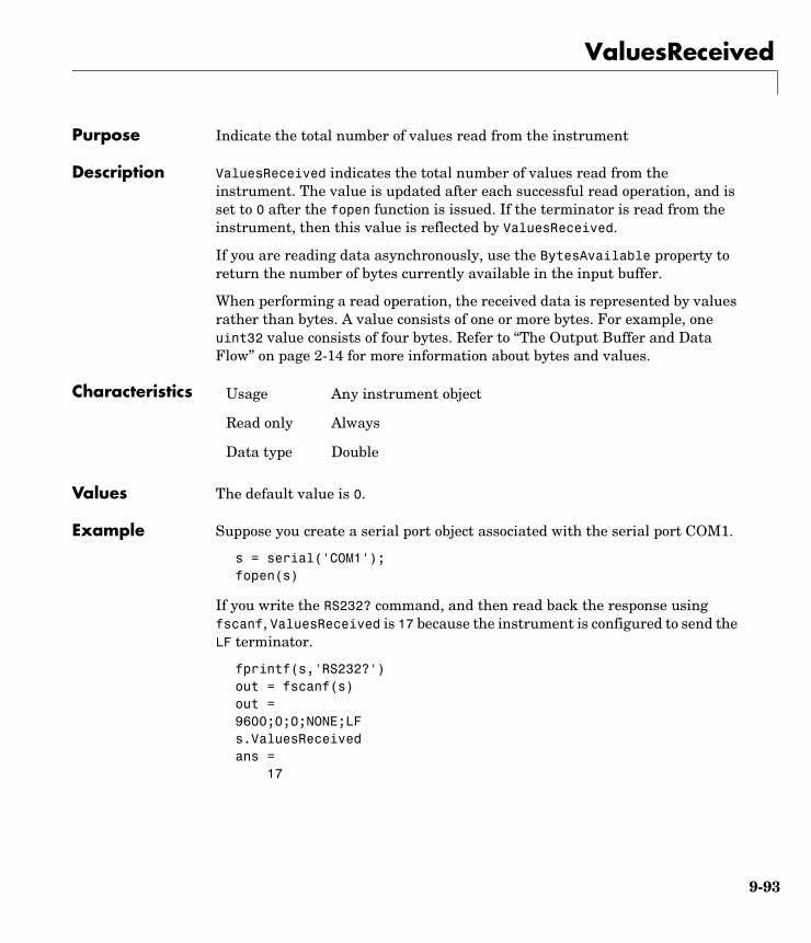
ValuesReceived
9-93
9ValuesReceivedPurpose Indicate the total number of values read from the instrument
Description ValuesReceived indicates the total number of values read from the instrument. The value is updated after each successful read operation, and is set to 0 after the fopen function is issued. If the terminator is read from the instrument, then this value is reflected by ValuesReceived.
If you are reading data asynchronously, use the BytesAvailable property to return the number of bytes currently available in the input buffer.
When performing a read operation, the received data is represented by values rather than bytes. A value consists of one or more bytes. For example, one uint32 value consists of four bytes. Refer to “The Output Buffer and Data Flow” on page 2-14 for more information about bytes and values.
Characteristics
Values The default value is 0.
Example Suppose you create a serial port object associated with the serial port COM1.
s = serial('COM1');fopen(s)
If you write the RS232? command, and then read back the response using fscanf, ValuesReceived is 17 because the instrument is configured to send the LF terminator.
fprintf(s,'RS232?')out = fscanf(s)out =9600;0;0;NONE;LFs.ValuesReceivedans = 17
Usage Any instrument object
Read only Always
Data type Double
ValuesReceived
9-94
See Also Functionsfopen
PropertiesBytesAvailable
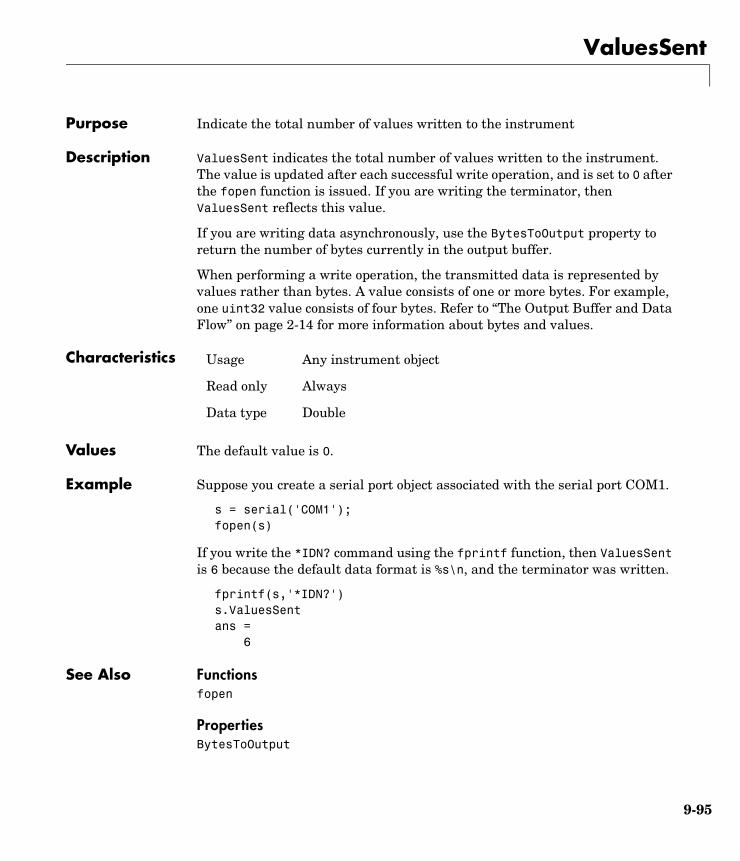
ValuesSent
9-95
9ValuesSentPurpose Indicate the total number of values written to the instrument
Description ValuesSent indicates the total number of values written to the instrument. The value is updated after each successful write operation, and is set to 0 after the fopen function is issued. If you are writing the terminator, then ValuesSent reflects this value.
If you are writing data asynchronously, use the BytesToOutput property to return the number of bytes currently in the output buffer.
When performing a write operation, the transmitted data is represented by values rather than bytes. A value consists of one or more bytes. For example, one uint32 value consists of four bytes. Refer to “The Output Buffer and Data Flow” on page 2-14 for more information about bytes and values.
Characteristics
Values The default value is 0.
Example Suppose you create a serial port object associated with the serial port COM1.
s = serial('COM1');fopen(s)
If you write the *IDN? command using the fprintf function, then ValuesSent is 6 because the default data format is %s\n, and the terminator was written.
fprintf(s,'*IDN?')s.ValuesSentans = 6
See Also Functionsfopen
PropertiesBytesToOutput
Usage Any instrument object
Read only Always
Data type Double

ValuesSent
9-96

A
Selected Bibliography

A
A-2
[1] Axelson, Jan, Serial Port Complete, Lakeview Research, Madison, WI, 1998.
[2] Courier High Speed Modems User’s Manual, U.S. Robotics, Inc., Skokie, IL, 1994.
[3] TIA/EIA-232-F, Interface Between Data Terminal Equipment and Data Circuit-Terminating Equipment Employing Serial Binary Data Interchange.
[4] Getting Started with Your AT Serial Hardware and Software for Windows 98/95, National Instruments, Inc., Austin, TX, 1998.
[5] HP E1432A User’s Guide, Hewlett-Packard Company, Palo Alto, CA, 1997.
[6] HP 33120A Function Generator/Arbitrary Waveform Generator User’s Guide, Hewlett-Packard Company, Palo Alto, CA, 1997.
[7] HP VISA User’s Guide, Hewlett-Packard Company, Palo Alto, CA, 1998.
[8] NI-488.2MTM User Manual for Windows 95 and Windows NT, National Instruments, Inc., Austin, TX, 1996.
[9] NI-VISATM User Manual, National Instruments, Inc., Austin, TX, 1998.
[10] IEEE Std 488.2-1992, IEEE Standard Codes, Formats, Protocols, and Common Commands for Use with IEEE Std 4881.-1987, IEEE Standard Digital Interface for Programmable Instrumentation, Institute of Electrical and Electronics Engineers, New York, NY, 1992.
[11] Instrument Communication Handbook, IOTech, Inc., Cleveland, OH, 1991.
[12] TDS 200-Series Two Channel Digital Oscilloscope Programmer Manual, Tektronix, Inc., Wilsonville, OR.
[13] Stevens, W. Richard. TCP/IP Illustrated, Volume 1, Addison-Wesley, Boston, MA, 1994.
I-1
Index
AA16/A24/A32 memory space 4-14active state, serial port 5-6adaptors 1-4
finding with instrhwinfo 1-13address configuration
GPIB object 3-20VISA-GPIB object 4-7VISA-GPIB-VXI object 4-24VISA-VXI object 4-12
Agilent Technologiesadaptors 1-4E1432A registers, example of 4-16VISA Assistant tool 4-3
array, instrument objectcreating 2-3example of 3-39
ASCIIcontrol characters 5-33read operations 2-22, 3-22serial data 5-9write operations 2-16, 3-22
ASCII Communication Tool 8-52asynchronous
read operations 2-23readasync, example of 3-24, 3-35ReadAsyncMode, example of 5-20
serial port 5-10write operations 2-17
ATN line 3-6serial poll 3-1, 3-39
Bbase properties 2-6
list of all 9-2BaudRate property 9-11
binaryfloating-point arithmetic standard 7-7read operations 2-22, 3-24write operations 2-16
binblockread function 8-8binblockwrite function 8-10BoardIndex
GPIB object 3-20VISA-GPIB object 4-8VISA-GPIB-VXI object 4-25
BoardIndex property 9-12break-interrupt event 5-25, 6-20BreakInterruptFcn property 9-13buffer
clearing hardware 3-29input 2-20output 2-14values versus bytes 2-14
bus and connector, GPIB 3-3BusManagementStatus
GPIB interface management lines 3-7BusManagementStatus property 9-14
example of 9-14ByteOrder property 9-16bytes versus values 2-14BytesAvailable
example of 2-24input buffer 2-20
bytes-available event 3-31example of 3-35
BytesAvailable property 9-17BytesAvailableFcn property 9-18BytesAvailableFcnCount property 9-21BytesAvailableFcnMode property 9-22BytesToOutput
output buffer 2-14
Index
I-2
BytesToOutput property 9-24
Ccallback functions
creating 3-33enabling after they error 3-34executing 3-33instrcallback, example of 3-30
callback propertiesGPIB object 3-31saving property values to a MAT-file 7-2serial port object 5-24, 6-19
CD pin 5-9ChassisIndex property 9-25clear
cleaning up the MATLAB environment 2-25clear function 8-12clrdevice
example of 3-29clrdevice function 8-13CompareBits property 9-26Configuration Tool 8-55configuring property values 2-9connecting to the instrument 2-5constructor 2-2
finding with instrhwinfo 1-14Contents 1-9control characters 5-33control pins 5-8, 5-29controllers, GPIB 3-3creation function 2-2CTS pin 5-8
Ddata bits 5-12
data formatserial port 5-9
data lines 3-6DataBits property 9-27DatagramAddress property 9-28DatagramPort property 9-29DatagramReceivedFcn property 9-30DatagramTerminateMode property 9-31DataTerminalReady property 9-32DAV line 3-7DCE 5-3dec2bin 7-8default property values 2-10delete
cleaning up the MATLAB environment 2-25delete function 8-14demos 1-9DIO lines 3-6disconnecting from the instrument 2-25disp function 8-15display summary
GPIB object 3-19serial port object 5-17TCP/IP object 6-5UDP object 6-9VISA-GPIB object 4-6VISA-GPIB-VXI object 4-23VISA-serial object 4-27VISA-VXI object 4-11
documentation examples 1-9dot notation
configuring property values 2-9returning property values 2-8saving property values to an M-file 7-2
DSR pin 5-8DTE 5-3DTR pin 5-8
Index
I-3
Eechotcpip function 8-16echoudp function 8-17enable registers 3-9EOI line 3-6
example of 3-27EOIMode
example of 3-27EOIMode property 9-33EOS character 3-27
EOSCharCode 9-34EOSCharCode
example of 3-27EOSCharCode property 9-34EOSMode
example of 3-27EOSMode property 9-35error event 3-31ErrorFcn property 9-37ESER 3-12even parity 5-12event reporting 3-9event types
GPIB object 3-31serial port object 5-24, 6-19
events 1-3example index 1-9examples
communicating with a GPIB instrument 1-5communicating with a GPIB-VXI instrument
1-6communicating with a serial port instrument
1-7connecting two modems 5-29executing a serial poll 3-39executing a trigger, GPIB 3-37parsing input data using scanstr 3-26
reading binary data, GPIB 3-24reading text data versus reading binary data
2-22recording information to disk 7-9understanding EOI and EOS 3-27using events and callbacks, GPIB 3-35using events and callbacks, serial port 5-27using software handshaking 5-34writing and reading text data, GPIB 3-22writing and reading text data, serial port 5-21writing text data versus writing binary data
2-16
Ffclose
disconnecting from the instrument 2-25fclose function 8-18fgetl
reading text data 2-22fgetl function 8-19
example of 8-20fgets
reading text data 2-22fgets function 8-22
example of 8-23FlowControl
example of 5-34FlowControl property 9-38flushinput function 8-25flushoutput function 8-26fopen
connecting to the instrument 2-5fopen function 8-27format
record file 7-7serial data 5-9

Index
I-4
fprintf
example of 3-23writing text data 2-16
fprintf function 8-29fread
example of 3-24reading binary data 2-22
fread function 8-32free serial port from MATLAB 8-36freeserial function 8-36fscanf
example of 3-23reading text data 2-22
fscanf function 8-37full-duplex 5-7function handles 3-33functions
binblockread 8-8binblockwrite 8-10clear 2-25, 8-12clrdevice 3-29, 8-13delete 2-25, 8-14disp 8-15echotcpip 8-16echoudp 8-17fclose 2-25, 8-18fgetl 2-22, 8-19fgets 2-22, 8-22flushinput 8-25flushoutput 8-26fopen 2-5, 8-27fprintf 2-16, 3-23, 8-29fread 2-22, 3-24, 8-32freeserial 8-36fscanf 2-22, 3-23, 8-37fwrite 2-16, 8-41get 2-7, 8-45
gpib 3-18, 8-47inspect 8-50instrbreak 8-103instrcallback 3-30, 3-35, 8-51instrcomm 8-52instrcreate 8-55instrfind 8-60instrhelp 1-17, 8-62instrhwinfo 1-13, 8-65instrreset 8-68instrschool 1-9, 8-69isvalid 8-70length 8-71load 7-4, 8-72memmap 8-74mempeek 8-76mempoke 8-78memread 8-80memunmap 8-82memwrite 8-83obj2mfile 7-2, 8-85propinfo 1-18, 8-87query 8-89readasync 2-23, 3-24, 3-35, 8-91record 7-9, 8-94resolvehost 8-96save 8-97scanstr 8-99serial 5-16, 8-101set 2-6, 2-9, 8-104size 8-106spoll 3-40, 8-107stopasync 8-109tcpip 6-4, 8-110trigger 3-37, 8-112udp 6-8, 8-113visa 8-116
Index
I-5
fwrite
example of 2-17writing binary data 2-16
fwrite function 8-41
Gget
GPIB object properties 2-7get function 8-45gpib
creating a GPIB object 3-18gpib function 8-47GPIB object
address configuration 3-20base properties 9-2callback properties 3-31creation 3-18display summary 3-19event types 3-31events and callbacks 3-30object-specific properties 9-4
GPIB standard 3-2bus and connector 3-3controllers 3-3data 3-4data lines 3-6enable registers 3-9event reporting 3-9handshake lines 3-7interface management lines 3-6listeners 3-3status registers 3-9talkers 3-3
GPIB-VXI interface 4-21graphical tools
instrcomm 8-52
instrcreate 8-55Measurement & Automation tool, NI 3-14VISA Assistant tool, Agilent 4-3VISA Interactive Control tool, NI 4-4
Group Execute Trigger 3-37GUI
instrcomm 8-52instrcreate 8-55Property Inspector 2-11
Hhalf-duplex 5-7handshake lines 3-7HandshakeStatus
GPIB handshake lines 3-9HandshakeStatus property 9-39handshaking
hardware 5-32serial port object 5-32software 5-33
hardware handshaking 5-32hardware resources 1-13help 1-17hex2dec 7-8hexadecimal values
converting to decimal values 7-8saved to record file 7-11
high-level memory functions, VXI 4-16HP-IB 3-2
IIEEE
488 standard 3-2754 standard 7-7format saved to record file 7-7
Index
I-6
IFC line 3-6inactive state, serial port 5-6input buffer 2-20InputBufferSize
input buffer 2-20InputBufferSize property 9-40inspect function 8-50instrbreak function 8-103instrcallback
example of 3-30, 3-35instrcallback function 8-51instrcomm function 8-52instrcreate function 8-55instrfind
example of 8-61instrfind function 8-60instrhelp
example of 1-17instrhelp function 8-62instrhwinfo
adaptors, finding 1-13example of 1-13object constructors, finding 1-14
instrhwinfo function 8-65instrreset function 8-68instrschool
example of 1-9instrschool function 8-69instrument control session 2-1
loading 7-2saving 7-2
instrument object 2-2array
creating 2-3example of 3-39
base properties 9-2configuring property values 2-9
during object creation 2-3connecting to instrument 2-5creating 2-2disconnecting from instrument 2-25input buffer 2-20invalid 2-25loading 7-2object-specific properties 9-4output buffer 2-14reading data 2-19returning from memory 8-60returning property values 2-6saving 7-2specifying property names 2-9writing data 2-13
interfacedriver adaptor 1-4GPIB object 3-18serial port object 5-16TCP/IP object 6-4UDP object 6-8VISA-GPIB object 4-5VISA-GPIB-VXI object 4-22VISA-serial object 4-26VISA-VXI object 4-10
interface management lines 3-6InterruptFcn property 9-41invalid instrument object 2-25isvalid function 8-70
Llength function 8-71listeners 3-3load 7-4load function 8-72
Index
I-7
loading instrument objectsMAT-file, from 7-4M-file, from 7-3
LocalHost property 9-42LocalPort property 9-43LocalPortMode property 9-44logical unit 3-20LogicalAddress property 9-45low-level memory functions, VXI 4-18
MMappedMemoryBase property 9-46MappedMemorySize property 9-47mark parity 5-12MAT-file
instrument objects, saving to 7-4properties, saving to 7-2
Measurement & Automation tool, NI 3-14memmap function 8-74memory mapping, VXI 4-18MemoryBase property 9-48MemoryIncrement property 9-50MemorySize property 9-52MemorySpace property 9-53mempeek function 8-76mempoke function 8-78memread function 8-80memunmap function 8-82memwrite function 8-83message-based communication, VXI 4-13
NNagle’s algorithm 9-86Name property 9-55National Instruments
adaptors 1-4Measurement & Automation tool 3-14VISA Interactive Control tool 4-4
NDAC line 3-7NRFD line 3-7null modem cable 5-4
Oobj2mfile
example of 7-2obj2mfile function 8-85object constructor 2-2
finding with instrhwinfo 1-14object-specific properties 2-6
list by object type 9-4odd parity 5-12online help 1-17output buffer 2-14OutputBufferSize
output buffer 2-14OutputBufferSize property 9-57output-empty event 3-32OutputEmptyFcn property 9-58
Pparity bit 5-12Parity property 9-59parsing input data 3-26PinStatus
example of 5-30pin-status event 5-25PinStatus property 9-60PinStatusFcn property 9-61Port property 9-62

Index
I-8
PrimaryAddress
GPIB object 3-20VISA-GPIB object 4-8VISA-GPIB-VXI object 4-25
PrimaryAddress property 9-63properties
BaudRate 9-11BoardIndex 3-20, 9-12BreakInterruptFcn 9-13BusManagementStatus 3-7, 9-14ByteOrder 9-16BytesAvailable 2-20, 9-17BytesAvailableFcn 9-18BytesAvailableFcnCount 9-21BytesAvailableFcnMode 9-22BytesToOutput 2-14, 9-24characteristics 1-18ChassisIndex 9-25CompareBits 9-26DataBits 9-27DatagramAddress 9-28DatagramPort 9-29DatagramReceivedFcn 9-30DatagramTerminateMode 9-31DataTerminalReady 9-32EOIMode 3-27, 9-33EOSCharCode 3-27, 9-34EOSMode 3-27, 9-35ErrorFcn 9-37FlowControl 9-38HandshakeStatus 3-9, 9-39InputBufferSize 2-20, 9-40InterruptFcn 9-41LocalHost 9-42LocalPort 9-43LocalPortMode 9-44LogicalAddress 9-45
MappedMemoryBase 9-46MappedMemorySize 9-47MemoryBase 9-48MemoryIncrement 9-50MemorySize 9-52MemorySpace 9-53Name 3-18, 9-55OutputBufferSize 2-14, 9-57OutputEmptyFcn 9-58Parity 9-59PinStatus 9-60PinStatusFcn 9-61Port 9-62PrimaryAddress 3-20, 9-63ReadAsyncMode 9-64RecordDetail 7-7, 7-9, 9-66RecordMode 7-6, 7-9, 9-67RecordName 7-6, 7-9, 9-69RecordStatus 9-70RemoteHost 9-71RemotePort 9-72RequestToSend 9-73RsrcName 9-74SecondaryAddress 3-20, 9-76Slot 9-78Status 2-5, 9-79StopBits 9-80Tag 9-81Terminator 5-30, 9-82Timeout 9-83TimerFcn property 9-84TimerPeriod property 9-85TransferDelay 9-86TransferStatus 9-87TriggerFcn 9-88TriggerLine 9-89TriggerType 9-90
Index
I-9
Type 3-18, 9-91UserData 9-92ValuesReceived 9-93ValuesSent 9-95
Property Inspector 2-10property values
base 2-6, 9-2configuring 2-9
during object creation 2-3default 2-10object-specific 2-6, 9-4returning 2-6saving 7-2specifying names 2-9
propinfo
example of 1-18propinfo function 8-87
Qquery function 8-89
Rread operations
asynchronous 2-23, 3-24, 3-35binary 2-22, 3-24completing
GPIB object 3-22, 6-13serial port object 5-21
GPIB registers 3-13register-based, VXI 4-13synchronous 2-23text 2-22, 3-22
readasync
asynchronous read operations 2-23example of 3-24, 3-35
readasync function 8-91ReadAsyncMode
asynchronous read operations 5-19example of 5-20
ReadAsyncMode property 9-64record
example of 7-9record file
creating multiple files 7-6filename 7-6format 7-7
record function 8-94RecordDetail
example of 7-9format, record file 7-7
RecordDetail property 9-66RecordMode
example of 7-9multiple record files, creating 7-6
RecordMode property 9-67RecordName
example of 7-9specifying a record file name 7-6
RecordName property 9-69RecordStatus property 9-70register-based communication, VXI 4-13
high-level memory functions, example of 4-16low-level memory functions, example of 4-18
registersAgilent E1432A, example of 4-16reading and writing 3-13, 3-40Service Request Enable 3-11Standard Event Status 3-12Standard Event Status Enable 3-12Status Byte 3-11
release serial port from MATLAB 8-36RemoteHost property 9-71
Index
I-10
RemotePort property 9-72REN line 3-6RequestToSend 9-73resolvehost function 8-96resource name
finding with vendor tools 4-3visa input argument 8-116
returning objects from memory 8-60returning property values 2-6RI pin 5-9RS-232 standard 5-2RsrcName property 9-74RTS pin 5-8
Ssave function 8-97saving instrument objects
MAT-file, to 7-4M-file, to 7-2
SBR 3-11scanstr 3-26scanstr function 8-99SCPI 3-2SecondaryAddress
GPIB object 3-20VISA-GPIB object 4-8VISA-GPIB-VXI object 4-25
SecondaryAddress property 9-76serial
creating a serial port object 5-16serial function 8-101serial poll 3-39serial port
configuring via operating system 5-13connecting two devices 5-3data format 5-9
release from MATLAB 8-36RS-232 standard 5-2signal and pin assignments 5-5
serial port objectbase properties 9-2callback properties 5-24, 6-19configuring communications 5-18control pins 5-8, 5-29creation 5-16display summary 5-17event types 5-24, 6-19events and callbacks 5-24handshaking 5-32object-specific properties 9-5writing data 5-19, 6-12
Service Request Enable Register 3-11SESR 3-12session 2-1
loading 7-2saving 7-2
set
configuring property values 2-9GPIB object properties 2-6saving property values to an M-file 7-2
set function 8-104setserial 5-15signal state
GPIB 3-5serial port 5-6
size function 8-106Slot property 9-78software handshaking 5-33space parity 5-12spoll 3-40spoll function 8-107SRER 3-11
Index
I-11
SRQ line 3-6serial poll 3-1, 3-39
Standard Event Status Enable Register 3-12Standard Event Status Register 3-12start bit 5-11Status 2-5Status Byte Register 3-11Status property 9-79status registers 3-9stop bit 5-11stopasync function 8-109StopBits property 9-80stty 5-15synchronous
read operations 2-23serial port 5-10write operations 2-17
TTag property 9-81talkers 3-3TCP/IP object
creation 6-4display summary 6-5
tcpip
creating a TCP/IP object 6-4tcpip function 8-110tcpip object
object-specific properties 9-5, 9-6termination
EOSCharCode, example of 3-28read operations
GPIB object 3-22, 6-13serial port object 5-21
Terminator, example of 5-30write operations
GPIB object 3-21serial port object 5-20, 6-12
Terminator
example of 5-30Terminator property 9-82text
read operations 2-22, 3-22write operations 2-16, 3-22
Timeout property 9-83timer event 3-32toolbox components
interface driver adaptor 1-4M-files 1-3
TransferDelay property 9-86TransferStatus property 9-87trigger
example of 3-37trigger function 8-112TriggerFcn property 9-88TriggerLine property 9-89TriggerType property 9-90troubleshooting
GPIB instruments 3-14serial ports 5-13VISA instruments 4-3
Type property 9-91
Uudp function 8-113UDP object
creation 6-8display summary 6-9
udpl
creating a UDP object 6-8UserData
saving values to a MAT-file 7-2
Index
I-12
UserData property 9-92
Vvalues versus bytes 2-14ValuesReceived property 9-93ValuesSent property 9-95vendor tools
Measurement & Automation tool, NI 3-14VISA Assistant tool, Agilent 4-3VISA Interactive Control tool, NI 4-4
VISA Assistant tool, Agilent 4-3visa function 8-116VISA Interactive Control tool, NI 4-4VISA-GPIB object
address configuration 4-7base properties 9-2creation 4-5display summary 4-6object-specific properties 9-6
VISA-GPIB-VXI objectaddress configuration 4-24base properties 9-2creation 4-22display summary 4-23object-specific properties 9-8
VISA-serial objectbase properties 9-2communication configuration 4-28creation 4-26display summary 4-27object-specific properties 9-9
VISA-VXI objectaddress configuration 4-12base properties 9-2creation 4-10display summary 4-11
object-specific properties 9-7register-based communication 4-13
VXI interface 4-9
WWorkspace browser
Display Hardware Info 1-16Display Summary 3-19Instrument Help 1-17Property Inspector 2-10
write operationsasynchronous 2-17binary 2-16completing
GPIB object 3-21serial port object 5-20, 6-12
GPIB registers 3-13, 3-40register-based, VXI 4-13synchronous 2-17text 2-16, 3-22values versus bytes 2-14
XXoff 5-33Xon 5-33