Instructions-Parts ProProProXp™Xp™Xp™Electrostatic ......Instructions-Parts...
94
Instructions - Parts Pro Pro Pro Xp™ Xp™ Xp™ Electrostatic Electrostatic Electrostatic Air Air Air Spray Spray Spray Gun Gun Gun 3A2494N EN For For For use use use in in in Class Class Class I, I, I, Div. Div. Div. I Hazardous Hazardous Hazardous Locations Locations Locations using using using Group Group Group D materials. materials. materials. For For For use use use in in in Group Group Group II, II, II, Zone Zone Zone 1 Explosive Explosive Explosive Atmosphere Atmosphere Atmosphere Locations Locations Locations using using using Group Group Group IIA IIA IIA materials. materials. materials. For For For professional professional professional use use use only. only. only. Important Important Important Safety Safety Safety Instructions Instructions Instructions This equipment could present hazards if not operated according to the information in this manual. Read all warnings and instructions in this manual before using the equipment. Save Save Save these these these instructions. instructions. instructions. 100 psi (0.7 MPa, 7.0 bar) Maximum Fluid Working Pressure 100 psi (0.7 MPa, 7.0 bar) Maximum Air Working Pressure See page 3 for model part numbers and approval information. PROVEN QUALITY. LEADING TECHNOLOGY.
Transcript of Instructions-Parts ProProProXp™Xp™Xp™Electrostatic ......Instructions-Parts...

Instructions - Parts
ProProPro Xp™Xp™Xp™ ElectrostaticElectrostaticElectrostaticAirAirAir SpraySpraySpray GunGunGun 3A2494N
EN
ForForFor useuseuse ininin ClassClassClass I,I,I, Div.Div.Div. III HazardousHazardousHazardous LocationsLocationsLocations usingusingusing GroupGroupGroup DDD materials.materials.materials.ForForFor useuseuse ininin GroupGroupGroup II,II,II, ZoneZoneZone 111 ExplosiveExplosiveExplosive AtmosphereAtmosphereAtmosphere LocationsLocationsLocations usingusingusing GroupGroupGroup IIAIIAIIA materials.materials.materials. ForForFor professionalprofessionalprofessionaluseuseuse only.only.only.
ImportantImportantImportant SafetySafetySafety InstructionsInstructionsInstructionsThis equipment could present hazards if not operated according tothe information in this manual. Read all warnings and instructions inthis manual before using the equipment. SaveSaveSave thesethesethese instructions.instructions.instructions.
100 psi (0.7 MPa, 7.0 bar) MaximumFluid Working Pressure100 psi (0.7 MPa, 7.0 bar) Maximum AirWorking PressureSee page 3 for model part numbers andapproval information.
PROVEN QUALITY. LEADING TECHNOLOGY.

ContentsContentsContentsModels............................................................... 3Approvals........................................................... 7Related Manuals ................................................ 7Warnings ........................................................... 8Gun Overview .................................................... 11
How the Electrostatic Spray GunWorks ............................................ 11
Controls, Indicators, and Components ........... 12Smart Guns ................................................. 13
Installation.......................................................... 18Warning Sign............................................... 18Ventilate the Spray Booth ............................. 18Air Supply Line ............................................ 19Fluid Supply Line ......................................... 19Grounding ................................................... 21
Gun Setup.......................................................... 25Gun Setup Procedure................................... 25Soft Spray Gun Setup Procedure .................. 28HVLP Gun Setup Procedure ......................... 29Round Spray Gun Setup Procedure .............. 31Abrasive Material Gun Setup
Procedure ...................................... 33Check Gun Electrical Grounding ................... 34Check Fluid Resistivity ................................. 35Check Fluid Viscosity ................................... 35Flush Before Using Equipment...................... 35
Operation........................................................... 36Pressure Relief Procedure............................ 36Startup ........................................................ 37Shutdown .................................................... 37
Maintenance ...................................................... 38Daily Care and Cleaning Checklist ................ 38Flushing ...................................................... 38Clean the Gun Daily ..................................... 40Daily System Care ....................................... 41
Electrical Tests ................................................... 42Test Gun Resistance.................................... 42Test Power Supply Resistance ..................... 43Test Electrode Resistance ............................ 43
Troubleshooting.................................................. 44Spray Pattern Troubleshooting...................... 44Gun Operation Troubleshooting .................... 45Electrical Troubleshooting ............................ 46
Repair................................................................ 47Prepare the Gun for Service ......................... 47Air Cap and Nozzle Replacement.................. 48
Electrode Replacement ................................ 49Fluid Packing Rod Removal.......................... 50Packing Rod Repair ..................................... 50Barrel Removal ............................................ 52Barrel Installation ......................................... 52Power Supply Removal and
Replacement .................................. 53Alternator Removal and Replacement ........... 54Fluid Tube Removal and Replacement ........... 56Fan Air Adjustment Valve Repair .................. 57Atomizing Air Restrictor Valve Repair ............ 58ES On-Off and Fluid Adjustment Valve
Repair............................................ 59Air Valve Repair........................................... 60Smart Module Replacement.......................... 61Air Swivel and Exhaust Valve
Replacement .................................. 62Parts.................................................................. 63
Gun Models with Standard Display................ 63Gun Models with Smart Display .................... 66Packing Rod Assembly................................. 69Alternator Assembly ..................................... 70ES On-Off and Fluid Adjustment Valve ........... 71Fan Air Adjustment Valve Assembly.............. 72Atomizing Air Restrictor Valve
Assembly ....................................... 72Smart Module Assembly............................... 73Round Spray Assembly ................................ 74High Conductivity Fluid Tube
Assembly ....................................... 76Fluid Nozzles ..................................................... 77
Fluid Nozzle Selection Chart......................... 77Fluid Nozzle Performance Charts.................. 78
Air Caps............................................................. 80Air Cap Selection Guide ............................... 80Air Consumption Charts ............................... 85
Electrode Selection Chart.................................... 86Repair Kits and Accessories................................ 87
Gun Accessories.......................................... 87Operator Accessories................................... 88System Accessories..................................... 88Signs .......................................................... 88Test Equipment ........................................... 89Hoses ......................................................... 90
Dimensions ........................................................ 91Notes ................................................................ 92Technical Specifications...................................... 93
2 3A2494N

Models
ModelsModelsModels
GeneralGeneralGeneral GunGunGun ModelsModelsModels
Equipped with standard electrode, nozzle, air cap and fluid tube. For applying a Class A finish with standardand specialty coatings.
PartPartPart No.No.No. SeriesSeriesSeries kVkVkV DisplayDisplayDisplay ElectrodeElectrodeElectrode NozzleNozzleNozzle(mm)(mm)(mm)
AirAirAir CapCapCap FluidFluidFluid TubeTubeTube
L40M10 A 40 Smart Std 1.5 Std Std Std
L40T10 C 40 Std Std 1.5 Std Std Std
L40T12 A 40 Std Std 1.2 Std Std Std
L60M10 C 60 Smart Std 1.5 Std Std Std
L60M12 C 60 Smart Std 1.2 Std Std Std
L60T10 C 60 Std Std 1.5 Std Std Std
L60T12 C 60 Std Std 1.2 Std Std Std
L60T21 A 60 Std Std 1.0 Std Std Std
L85M10 C 85 Smart Std 1.5 Std Std Std
L85M12 A 85 Smart Std 1.2 Std Std Std
L85T10 C 85 Std Std 1.5 Std Std Std
L85T12 A 85 Std Std 1.2 Std Std Std
L85T50* A 85 Std Std 1.5 Std Std Std
*Equipped with a quick-adjust fan valve
3A2494N 3

Models
HighHighHigh ConductivityConductivityConductivity GunGunGun ModelsModelsModels
Equipped with a longer High Conductivity fluid tube for spraying lower resistivity material. Most models arealso equipped with high wear electrode, precision high wear nozzle, and standard air cap. For applying aclass A finish with abrasive and metallic coatings.
PartPartPart No.No.No. SeriesSeriesSeries kVkVkV DisplayDisplayDisplay ElectrodeElectrodeElectrode NozzleNozzleNozzle(mm)(mm)(mm)
AirAirAir CapCapCap FluidFluidFluid TubeTubeTube
L40M16 A 40 Smart HW 1.5 PHW Std HC
L40T13 B 40 Std HW 1.5 Std Std HC
L40T16 C 40 Std HW 1.5 PHW Std HC
L40T26 A 40 Std HW 1.2 PHW Std HC
L60M26 A 60 Smart HW 1.2 PHW Std HC
L60M16 C 60 Smart HW 1.5 PHW Std HC
L60T26 A 60 Std HW 1.2 PHW Std HC
L60T13 B 60 Std HW 1.5 Std Std HC
L60T16 C 60 Std HW 1.5 PHW Std HC
L85M16 C 85 Smart HW 1.5 PHW Std HC
L85M26 A 85 Smart HW 1.2 PHW Std HC
L85T16 C 85 Std HW 1.5 PHW Std HC
L85T26 A 85 Std HW 1.2 PHW Std HC
L85T56* A 85 Std HW 1.5 PHW Std HC
*Equipped with a quick-adjust fan valve
kVkVkV BoosterBoosterBooster GunGunGun ModelsModelsModels
The 40 kV Booster provides the transfer efficiency of a 60 kV gun in a smaller, more compact size.
PartPartPart No.No.No. SeriesSeriesSeries kVkVkV DisplayDisplayDisplay ElectrodeElectrodeElectrode NozzleNozzleNozzle(mm)(mm)(mm)
AirAirAir CapCapCap FluidFluidFluid TubeTubeTube
L40M14 A 40 Smart Std 1.5 Std Std Std
L40M15 A 40 Smart HW 1.5 PHW Std HC
L40T14 C 40 Std Std 1.5 Std Std Std
L40T15 C 40 Std HW 1.5 PHW Std HC
4 3A2494N

Models
RoundRoundRound SpraySpraySpray GunGunGun ModelsModelsModels
Equipped with round spray nozzle and air cap. For round spray pattern applications.
PartPartPart No.No.No. SeriesSeriesSeries kVkVkV DisplayDisplayDisplay ElectrodeElectrodeElectrode NozzleNozzleNozzle(mm)(mm)(mm)
AirAirAir CapCapCap FluidFluidFluid TubeTubeTube
L40T31 A 40 Std Std Small Pattern Std
L40T32 A 40 Std Std Medium Pattern Std
L60T11 C 60 Std Std Large Pattern Std
L60T31 A 60 Std Std Small Pattern Std
L60T32 A 60 Std Std Medium Pattern Std
L85T31 A 85 Std Std Small Pattern Std
L85T32 A 85 Std Std Medium Pattern Std
SoftSoftSoft SpraySpraySpray GunGunGun ModelsModelsModels
Equipped with soft spray air cap. For applying a class A finish to small, lightweight parts.
PartPartPart No.No.No. SeriesSeriesSeries kVkVkV DisplayDisplayDisplay ElectrodeElectrodeElectrode NozzleNozzleNozzle(mm)(mm)(mm)
AirAirAir CapCapCap FluidFluidFluid TubeTubeTube
L40T71 A 40 Std Std 1.0 Std Soft Spray Std
L60M71 A 60 Smart Std 1.0 Std Soft Spray Std
L60M72 A 60 Smart Std 1.2 Std Soft Spray Std
L60T71 A 60 Std Std 1.0 Std Soft Spray Std
L60T72 A 60 Std Std 1.2 Std Soft Spray Std
L85M71 A 85 Smart Std 1.0 Std Soft Spray Std
L85T71 A 85 Std Std 1.0 Std Soft Spray Std
AerospaceAerospaceAerospace GunGunGun ModelsModelsModels
Equipped with aerospace air cap, high wear electrode, and precision high wear nozzle. For applying highsolids and aerospace coatings.
PartPartPart No.No.No. SeriesSeriesSeries kVkVkV DisplayDisplayDisplay ElectrodeElectrodeElectrode NozzleNozzleNozzle(mm)(mm)(mm)
AirAirAir CapCapCap FluidFluidFluid TubeTubeTube
L85T73 A 85 Std HW 1.2 PHW AERO Std
L85T75 A 85 Std HW 1.5 PHW AERO Std
L85T78 A 85 Std HW 1.8 PHW AERO Std
3A2494N 5
Models
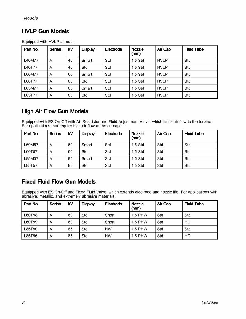
HVLPHVLPHVLP GunGunGun ModelsModelsModels
Equipped with HVLP air cap.
PartPartPart No.No.No. SeriesSeriesSeries kVkVkV DisplayDisplayDisplay ElectrodeElectrodeElectrode NozzleNozzleNozzle(mm)(mm)(mm)
AirAirAir CapCapCap FluidFluidFluid TubeTubeTube
L40M77 A 40 Smart Std 1.5 Std HVLP Std
L40T77 A 40 Std Std 1.5 Std HVLP Std
L60M77 A 60 Smart Std 1.5 Std HVLP Std
L60T77 A 60 Std Std 1.5 Std HVLP Std
L85M77 A 85 Smart Std 1.5 Std HVLP Std
L85T77 A 85 Std Std 1.5 Std HVLP Std
HighHighHigh AirAirAir FlowFlowFlow GunGunGun ModelsModelsModels
Equipped with ES On-Off with Air Restrictor and Fluid Adjustment Valve, which limits air flow to the turbine.For applications that require high air flow at the air cap.
PartPartPart No.No.No. SeriesSeriesSeries kVkVkV DisplayDisplayDisplay ElectrodeElectrodeElectrode NozzleNozzleNozzle(mm)(mm)(mm)
AirAirAir CapCapCap FluidFluidFluid TubeTubeTube
L60M57 A 60 Smart Std 1.5 Std Std Std
L60T57 A 60 Std Std 1.5 Std Std Std
L85M57 A 85 Smart Std 1.5 Std Std Std
L85T57 A 85 Std Std 1.5 Std Std Std
FixedFixedFixed FluidFluidFluid FlowFlowFlow GunGunGun ModelsModelsModels
Equipped with ES On-Off and Fixed Fluid Valve, which extends electrode and nozzle life. For applications withabrasive, metallic, and extremely abrasive materials.
PartPartPart No.No.No. SeriesSeriesSeries kVkVkV DisplayDisplayDisplay ElectrodeElectrodeElectrode NozzleNozzleNozzle(mm)(mm)(mm)
AirAirAir CapCapCap FluidFluidFluid TubeTubeTube
L60T98 A 60 Std Short 1.5 PHW Std Std
L60T99 A 60 Std Short 1.5 PHW Std HC
L85T90 A 85 Std HW 1.5 PHW Std Std
L85T96 A 85 Std HW 1.5 PHW Std HC
6 3A2494N

Approvals
ApprovalsApprovalsApprovals
2575IIIIII 222 GGG
0.24 mJ T6
FM12ATEX0068
EN 50050-1
Ta 0°C – 50°C
RelatedRelatedRelated ManualsManualsManualsManualManualManual No.No.No. DescriptionDescriptionDescription
3A2498 Round Spray Kit, Instructions (large pattern)
3A6929 Round Spray Kit, Instructions (small and medium pattern)
3A6833 HVLP Verification Kit, Instructions
307263 Probe and Meter, Instructions
308393 Gun Washer Kit, Instructions
309227 Gun Flush Box Module, Instructions
309455 Test Fixture, High Voltage Probe, and kV Meter, Instructions
406999 Voltage Tester Conversion Kit, Instructions
3A2494N 7

Warnings
WarningsWarningsWarningsThe following warnings are for the setup, use, grounding, maintenance, and repair of this equipment. Theexclamation point symbol alerts you to a general warning and the hazard symbols refer to procedure-specificrisks. When these symbols appear in the body of this manual or on warning labels, refer back to theseWarnings. Product-specific hazard symbols and warnings not covered in this section may appear throughoutthe body of this manual where applicable.
WARNINGWARNINGWARNINGFIRE,FIRE,FIRE, EXPLOSION,EXPLOSION,EXPLOSION, ANDANDAND ELECTRICELECTRICELECTRIC SHOCKSHOCKSHOCK HAZARDHAZARDHAZARD
Flammable fumes, such as solvent and paint fumes, in work area can ignite or explode. Paintor solvent flowing through the equipment can cause static sparking. To help prevent fire,explosion, and electric shock:
• Electrostatic equipment must be used only by trained, qualified personnel who understandthe requirements of this manual.
• Ground all equipment, personnel, object being sprayed, and conductive objects in or close tospray area. Resistance must not exceed 1 megohm. See GroundingGroundingGrounding instructions.
• Only use grounded Graco conductive air supply hoses.• Do not use pail liners unless they are conductive and grounded.• StopStopStop operationoperationoperation immediatelyimmediatelyimmediately if static sparking occurs or you feel a shock. Do not useequipment until you identify and correct the problem.
• Check gun resistance, hose resistance, and electrical grounding daily.• Use and clean equipment only in well ventilated area.• Interlock the gun air and fluid supply to prevent operation unless ventilation air flow is abovethe minimum required value.
• Use only Group IIA or Group D materials.• Use cleaning solvents with highest possible flash point when flushing or cleaning equipment.• Never spray or flush solvent at high pressure.• To clean the exterior of the equipment, cleaning solvents must have a flash point at least 15°C or 59° F above ambient temperature. Non-ignitable fluids are preferred.
• Always turn the electrostatics off when flushing, cleaning or servicing equipment.• Eliminate all ignition sources such as pilot lights, cigarettes, portable electric lamps, andplastic drop cloths (potential static sparking).
• Do not plug or unplug power cords or turn lights on or off when flammable fumes are present.• Keep work area free of debris, including solvent, rags and gasoline.• Keep the spray area clean at all times. Use non-sparking tools to clean residue from thebooth and hangers.
• Keep a working fire extinguisher in the work area.
8 3A2494N
Warnings
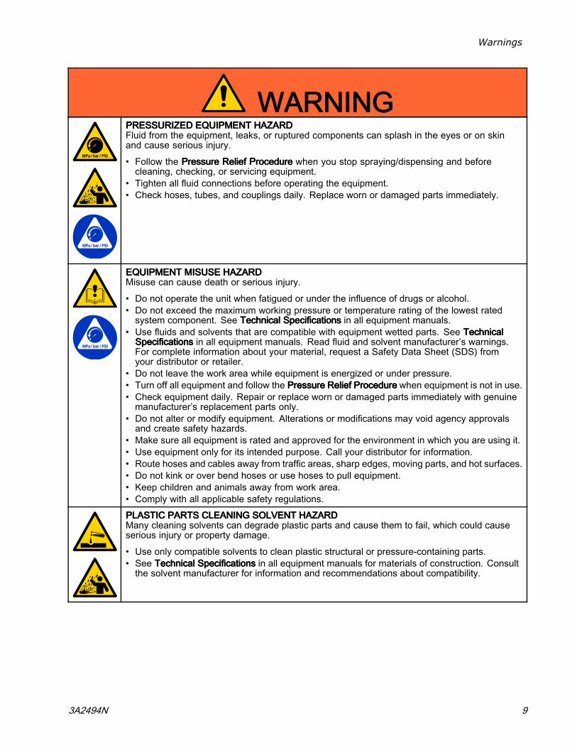
WARNINGWARNINGWARNINGPRESSURIZEDPRESSURIZEDPRESSURIZED EQUIPMENTEQUIPMENTEQUIPMENT HAZARDHAZARDHAZARDFluid from the equipment, leaks, or ruptured components can splash in the eyes or on skinand cause serious injury.
• Follow the PressurePressurePressure ReliefReliefRelief ProcedureProcedureProcedure when you stop spraying/dispensing and beforecleaning, checking, or servicing equipment.
• Tighten all fluid connections before operating the equipment.• Check hoses, tubes, and couplings daily. Replace worn or damaged parts immediately.
EQUIPMENTEQUIPMENTEQUIPMENT MISUSEMISUSEMISUSE HAZARDHAZARDHAZARDMisuse can cause death or serious injury.
• Do not operate the unit when fatigued or under the influence of drugs or alcohol.• Do not exceed the maximum working pressure or temperature rating of the lowest ratedsystem component. See TechnicalTechnicalTechnical SpecificationsSpecificationsSpecifications in all equipment manuals.
• Use fluids and solvents that are compatible with equipment wetted parts. See TechnicalTechnicalTechnicalSpecificationsSpecificationsSpecifications in all equipment manuals. Read fluid and solvent manufacturer’s warnings.For complete information about your material, request a Safety Data Sheet (SDS) fromyour distributor or retailer.
• Do not leave the work area while equipment is energized or under pressure.• Turn off all equipment and follow the PressurePressurePressure ReliefReliefRelief ProcedureProcedureProcedure when equipment is not in use.• Check equipment daily. Repair or replace worn or damaged parts immediately with genuinemanufacturer’s replacement parts only.
• Do not alter or modify equipment. Alterations or modifications may void agency approvalsand create safety hazards.
• Make sure all equipment is rated and approved for the environment in which you are using it.• Use equipment only for its intended purpose. Call your distributor for information.• Route hoses and cables away from traffic areas, sharp edges, moving parts, and hot surfaces.• Do not kink or over bend hoses or use hoses to pull equipment.• Keep children and animals away from work area.• Comply with all applicable safety regulations.
PLASTICPLASTICPLASTIC PARTSPARTSPARTS CLEANINGCLEANINGCLEANING SOLVENTSOLVENTSOLVENT HAZARDHAZARDHAZARDMany cleaning solvents can degrade plastic parts and cause them to fail, which could causeserious injury or property damage.
• Use only compatible solvents to clean plastic structural or pressure-containing parts.• See TechnicalTechnicalTechnical SpecificationsSpecificationsSpecifications in all equipment manuals for materials of construction. Consultthe solvent manufacturer for information and recommendations about compatibility.
3A2494N 9

Warnings
WARNINGWARNINGWARNINGTOXICTOXICTOXIC FLUIDFLUIDFLUID OROROR FUMESFUMESFUMES HAZARDHAZARDHAZARDToxic fluids or fumes can cause serious injury or death if splashed in the eyes or on skin,inhaled, or swallowed.
• Read Safety Data Sheet (SDS) to know the specific hazards of the fluids you are using.• Store hazardous fluid in approved containers, and dispose of it according to applicableguidelines.
PERSONALPERSONALPERSONAL PROTECTIVEPROTECTIVEPROTECTIVE EQUIPMENTEQUIPMENTEQUIPMENTWear appropriate protective equipment when in the work area to help prevent serious injury,including eye injury, hearing loss, inhalation of toxic fumes, and burns. This protectiveequipment includes but is not limited to:
• Protective eyewear, and hearing protection.• Respirators, protective clothing, and gloves as recommended by the fluid and solventmanufacturer.
10 3A2494N

Gun Overview
GunGunGun OverviewOverviewOverview
HowHowHow thethethe ElectrostaticElectrostaticElectrostatic SpraySpraySpray GunGunGun WorksWorksWorks
The air hose supplies air to the spray gun. Part ofthe air operates the alternator turbine and the restof the air atomizes the fluid being sprayed. Thealternator generates power, which is converted bythe power cartridge to supply high voltage to thegun’s electrode.
The pump supplies fluid to the fluid hose and gun,where the fluid is electrostatically charged as itpasses the electrode. The charged fluid is attractedto the grounded workpiece, wrapping around andevenly coating all surfaces.
3A2494N 11

Gun Overview
Controls,Controls,Controls, Indicators,Indicators,Indicators, andandand ComponentsComponentsComponents
The electrostatic gun includes the following controls, indicators, and components (see Fig. 1). For informationon Smart guns, see Smart Guns, page 13.
Figure 1 Gun Overview
ItemItemItem DescriptionDescriptionDescription PurposePurposePurpose
A Air Swivel Inlet 1/4 npsm(m) left-hand thread, for Graco grounded air supply hose.
B Fluid Inlet 3/8 npsm(m), for fluid supply hose.
C Turbine AirExhaust
Barbed fitting, for supplied exhaust tube.
D Air Cap and Nozzle Shapes the spray pattern. See Air Caps, page 80 andFluid Nozzles, page 77 for available sizes.
E Electrode Needle Supplies electrostatic charge to the fluid. SeeElectrode Selection Chart, page 86.
F Fan Air AdjustmentValve
Adjusts fan size and shape. Can be used to decrease pattern length.
G Atomizing AirRestrictor Valve
Restricts air cap air flow. Replace with plug (included) if desired.
H Fluid AdjustmentKnob
Adjusts fluid flow by limiting fluid needle travel. Use only in low flowconditions, to reduce wear.
J ES On-Off Valve Turns electrostatics ON (I) or OFF (O).
K ES Indicator (stan-dard gun only; forSmart gun indica-tor, see OperatingMode, page 13)
Lit when ES is ON (I). Color indicates alternator frequency. See the LEDindicator table in the Gun Setup Procedure, page 25.
12 3A2494N

Gun Overview
SmartSmartSmart GunsGunsGuns
The Smart Gun module displays spraying voltage,current, alternator speed, and the voltage setting (lowor high). It also allows the user to change to a lowerspraying voltage. The module has two modes:
• Operating Mode• Diagnostic Mode
OperatingOperatingOperating ModeModeMode
BarBarBar GraphGraphGraph
See Fig. 2 and Smart Gun Key, page 15. TheOperating Mode displays gun data during normalspraying. The display uses a bar graph to show thevoltage level in kiloVolts (kV) and the current level inmicroAmperes (uA). The bar graph range is from 0to 100% for each value.
If the bar graph LEDs are blue, the gun is ready tospray. If the LEDs are yellow or red, the current istoo high. The fluid may be too conductive, or seeElectrical Troubleshooting, page 46 for other possiblecauses.
HzHzHz IndicatorIndicatorIndicator
The Hz indicator functions the same as the ESindicator on standard guns. The indicator lights toshow the alternator speed status, and has threecolors:
• Green indicates the alternator speed is correct.• If the indicator changes to amber after one second,increase the air pressure.
• If the indicator changes to red after one second,the air pressure is too high. Decrease air pressureuntil the indicator is green. To maintain a higherair pressure, install ES On/Off Valve Restrictor Kit26A160. Then, adjust the pressure as needed toensure the indicator remains green.
VoltageVoltageVoltage AdjustmentAdjustmentAdjustment SwitchSwitchSwitch
The voltage adjustment switch (VA) allows theoperator to change from low to high voltage.
• The high voltage setting is determined by themaximum voltage of the gun and is not adjustable.
• The low voltage indicator (LO) lightswhen the switch is set to LO. The lowvoltage setting is user adjustable. SeeAdjusting the Low Voltage Setting, page 14.
NOTE:NOTE:NOTE: If the Error display appears, the Smart modulehas lost communication with the power supply. SeeError Display, page 14, for further information.
Figure 2 Smart Gun Module in Operating Mode
3A2494N 13

Gun Overview
ErrorErrorError DisplayDisplayDisplay
If the Smart module loses communication withthe power supply, the Error display appears, theHz indicator turns red, and the Smart module isdisabled. See Fig. 3 and Smart Gun Key, page 15.This can occur in Operating Mode or DiagnosticMode. See Electrical Troubleshooting, page 46.Communication must be restored to make the Smartmodule functional.NOTE:NOTE:NOTE: It takes 8 seconds for the Error display toappear. If the gun has been disassembled, wait 8seconds before spraying to ensure that an Errorcondition has not occurred.NOTE:NOTE:NOTE: If there is no power to the gun, the Errordisplay will not appear.
Figure 3 Error Display
AdjustingAdjustingAdjusting thethethe LowLowLow VoltageVoltageVoltage SettingSettingSetting
The low voltage setting is user adjustable. To accessthe low voltage setting screen when in OperatingMode, press the LO SET button (LS) momentarily.The screen will display the current low voltagesetting. See Fig. 4 and Smart Gun Key, page 15.The possible ranges are:• 85 kV guns: 40–85 kV• 60 kV guns: 30–60 kV• 40 kV guns: 20–40 kVSet the Voltage Adjustment switch (VA) to LO. Pressthe LO SET button repeatedly to increase the settingin increments of 5. When the display reaches themaximum setting it will return to the minimum setting
for your gun. Continue pressing the button until youreach the desired setting.
NOTE:NOTE:NOTE: After 2 seconds of inactivity the display willreturn to the Operating Screen.
NOTE:NOTE:NOTE: The low voltage setting may be locked. SeeLock Symbol, page 14.
Figure 4 Low Voltage Setting Screen (Unlocked)
LockLockLock SymbolSymbolSymbol
The low voltage setting may be locked. When locked,an image (LK) appears on the screen. See Fig. 5and Smart Gun Key, page 15.
• When in HI mode, the low voltage setting is alwaysalwaysalwayslocked. The lock symbol will appear when the LOSET button is pressed.
• When in LO mode, the lock symbol willonlyonlyonly appear if the lock is enabled. SeeLow Voltage Lock Screen, page 17, to lock orunlock the low voltage setting.
Figure 5 Low Voltage Setting Screen (Locked)
14 3A2494N

Gun Overview
SmartSmartSmart GunGunGun KeyKeyKey
TableTableTable 111 KeyKeyKey forforfor Figs.Figs.Figs. 2–9.2–9.2–9.
ItemItemItem DescriptionDescriptionDescription PurposePurposePurpose
VA Voltage Adjustment Switch Two-position switch sets Smart gun voltage to low setting (LO) orhigh setting (HI). This switch is functional in Operating Mode and inDiagnostic Mode.
LO Low Voltage ModeIndicator
Lights (blue) when the Smart gun is set to Low Voltage.
kV Voltage (kV) Display Displays actual spraying voltage of the gun, in kV. In Operating Mode,display is a bar graph. In Diagnostic Mode, voltage is displayed asa number.
uA Current (uA) Display Displays actual spraying current of the gun, in uA. In Operating Mode,display is a bar graph. In Diagnostic Mode, current is displayed asa number.
LS LO SET button Press momentarily to enter the Low Voltage Setting screen.
Press and hold for approximately 5 seconds to enter or exit DiagnosticMode.
While in Diagnostic Mode, press momentarily to advance throughscreens.
While on the Low Voltage Lock Screen (in Diagnostic Mode), pressand hold to turn the lock on or off.
LV Low Voltage Display Displays the low voltage setting as a number. The setting can bechanged. See Fig. 4.
LK Low Voltage Locked Appears if the low voltage setting is locked. See Fig. 5 and Fig. 9.
LD LO Display Appears on the Low Voltage Lock Screen. See Fig. 9.
ER Error Display Appears if the Smart module loses communication with the powersupply. See Fig. 3.
VI Voltage Indicator In Diagnostic Mode, the two top right LEDs of the screen light,indicating that the value displayed is in kV. See Fig. 6.
CI Current Indicator In Diagnostic Mode, the two bottom right LEDs of the screen light,indicating that the value displayed is in uA. See Fig. 7.
AS Alternator Speed Display In Diagnostic Mode, Hz level is displayed as a number. See Fig. 8.
Hz Alternator Speed Indicator In Operating Mode, indicator color varies to show the alternator speedstatus:
• Green indicates the alternator speed is at the correct level.• If the indicator changes to amber after one second, the alternatorspeed is too low.
• If the indicator changes to red after one second, the alternator speedis too high. The indicator also turns red if the Error display appears.
In Diagnostic Mode, the indicator is green when in the AlternatorSpeed (Hertz) screen.
3A2494N 15

Gun Overview
DiagnosticDiagnosticDiagnostic ModeModeMode
Diagnostic Mode includes four screens which displaygun data:
• Voltage (kiloVolts) Screen• Current (microAmperes) Screen• Alternator Speed (Hertz) Screen• Low Voltage Lock Screen
NOTE:NOTE:NOTE: You must be in Operating Mode to adjust thelow voltage setting; the setting is not adjustable inDiagnostic Mode. However, the voltage adjustmentswitch (VA) can be set to HI or LO in Operating Modeand in Diagnostic Mode.
To enter Diagnostic Mode, press and hold the LO SET(LS) button for approximately 5 seconds. The displaywill go to the Voltage (kiloVolts) Screen, page 16.
To advance to the next screen, press the LO SETbutton again.
To exit Diagnostic Mode, press and hold the LO SETbutton for approximately 5 seconds. The screen willreturn to Operating Mode.
NOTE:NOTE:NOTE: If the gun is detriggered while in DiagnosticMode, the last screen viewed will be displayed whenthe gun is retriggered.
NOTE:NOTE:NOTE: Diagnostic Mode cannot be exitedfrom the Low Voltage Lock Screen. SeeLow Voltage Lock Screen, page 17 for details.
VoltageVoltageVoltage (kiloVolts)(kiloVolts)(kiloVolts) ScreenScreenScreen
The Voltage (kiloVolts) Screen is the first screen toappear after entering Diagnostic Mode. See Fig. 6and Smart Gun Key, page 15. To enter this screen,press and hold the LO SET button for approximately5 seconds while in the Operating Mode.
This screen displays the spraying voltage of thegun as a number (kV), rounded to the nearest 5 kV.The two top right LEDs (VI) of the display panellight, indicating that the Voltage (kiloVolts) Screenis displayed. The display is a readout and cannotbe changed.
Press the LO SET button to advance to theCurrent (microAmperes) Screen, page 16. Pressand hold for approximately 5 seconds to return toOperating Mode.
Figure 6 Voltage (kiloVolts) Screen
CurrentCurrentCurrent (microAmperes)(microAmperes)(microAmperes) ScreenScreenScreen
The Current (microAmperes) Screen is the secondscreen in the Diagnostic Mode. See Fig. 7 andSmart Gun Key, page 15. To enter this screen, pressthe LO SET button while in the Voltage (kiloVolts)Screen.
This screen displays the spraying current of the gunas a number (uA), rounded to the nearest 5 uA. Thetwo bottom right LEDs (CI) of the display panel light,indicating that the Current (microAmperes) Screenis displayed. The display is a readout and cannotbe changed.
Press the LO SET button to advance to theAlternator Speed (Hertz) Screen, page 17. Pressand hold for approximately 5 seconds to return toOperating Mode.
Figure 7 Current (microAmperes) Screen
16 3A2494N

Gun Overview
AlternatorAlternatorAlternator SpeedSpeedSpeed (Hertz)(Hertz)(Hertz) ScreenScreenScreen
The Alternator Speed (Hertz) Screen is the thirdscreen in the Diagnostic Mode. See Fig. 8 andSmart Gun Key, page 15. To enter this screen,press the LO SET button while in the Current(microAmperes) Screen.
This screen displays the alternator speed as a 3 digitnumber (AS), rounded to the nearest 10 Hz. Thedisplay is a readout and cannot be changed. If thealternator speed is greater than 999 Hz, the displaywill show 999.
The Hz indicator lights green to show that you areviewing the Alternator Speed (Hertz) Screen.
Press the LO SET button to advance to theLow Voltage Lock Screen, page 17. Press and holdfor approximately 5 seconds to return to OperatingMode.
Figure 8 Alternator Speed (Hertz) Screen
LowLowLow VoltageVoltageVoltage LockLockLock ScreenScreenScreen
The Low Voltage Lock Screen is the fourthscreen in the Diagnostic Mode. See Fig. 9 andSmart Gun Key, page 15. To enter this screen, pressthe LO SET button while in the Alternator Speed(Hertz) Screen.
This screen displays the status of the Low VoltageLock. If the setting is locked, the lock image (LK)appears to the left of the Lo display (LD). If the settingis unlocked, the lock image does not appear.
To change the lock status, press and hold theLO SET button until the lock image appears ordisappears. If the lock is set, the image will alsoappear on the Low Voltage Setting Screen when inlow voltage mode (see Fig. 4).
NOTE:NOTE:NOTE: Diagnostic Mode cannot be exited from thisscreen, because pressing and holding the LO SETbutton is used to turn the lock on or off. To exit,press LO SET momentarily to return to the Voltage(kiloVolts) Screen, then exit Diagnostic Mode fromthere.
Figure 9 Low Voltage Lock Screen
3A2494N 17

Installation
InstallationInstallationInstallation
Installing and servicing this equipment requiresaccess to parts which may cause electric shockor other serious injury if work is not performedproperly.
• Do not install or service this equipment unlessyou are trained and qualified.
• Be sure your installation complies with local,state, and national codes for the installationof electrical apparatus in a Class I, Div. I,hazardous location or a Group II, Zone Iexplosive atmosphere location.
• Comply with all local codes and regulations.
Fig. 10 (Typical Installation) shows a typicalelectrostatic air spray system. It is not an actualsystem design. For assistance in designing a systemto suit your particular needs, contact your Gracodistributor.
WarningWarningWarning SignSignSign
Mount warning signs in the spray area where theycan easily be seen and read by all operators. AnEnglish Warning Sign is provided with the gun.
VentilateVentilateVentilate thethethe SpraySpraySpray BoothBoothBooth
Do not operate the gun unless ventilating air flow isabove the minimum required value. Provide freshair ventilation to avoid the buildup of flammable ortoxic vapors when spraying, flushing, or cleaningthe gun. Interlock the gun air and fluid supplyto prevent operation unless ventilating air flow isabove the minimum required value.
The spray booth must have a ventilation system.
Electrically interlock the gun air and fluid supply withthe ventilators to prevent gun operation any time thatthe ventilation air flow falls below minimum values.Check and follow all local codes and regulationsregarding air exhaust velocity requirements. Verifythe operation of the interlock at least once a year.
NOTE: The minimum allowable air exhaustvelocity is 60 feet/minute (19 linear meters/minute).High-velocity air exhaust will decrease the operatingefficiency of the electrostatic system.
18 3A2494N

Installation
AirAirAir SupplySupplySupply LineLineLine
To reduce the risk of electric shock, the air supplyhose must be electrically connected to a true earthground. UseUseUse onlyonlyonly GracoGracoGraco GroundedGroundedGrounded AirAirAir SupplySupplySupplyHose.Hose.Hose.
1. See Fig. 10. Use the Graco Grounded Air SupplyHose (AH) to supply air to the gun. The gun airinlet fitting has a left-hand thread. The air supplyhose ground wire (AG) must be connected to atrue earth ground. Do not connect the air supplyhose to the gun air inlet yet.
2. Install an air line filter/water separator (AF) on thegun air line to ensure a dry, clean air supply to thegun. Dirt and moisture can ruin the appearanceof your finished workpiece and can cause thegun to malfunction.
3. Install bleed-type air regulators (PR, GR) onthe pump and gun air supply lines to control airpressure to the pump and gun.
Trapped air can cause the pump to cycleunexpectedly, which can result in seriousinjury, including splashing fluid in the eyes oron the skin. Do not operate the equipmentwithout the bleed-type air valve (BV) installed.
4. Install a bleed-type air valve (BV) on the pumpair supply line. The bleed-type air valve (BV) isrequired in your system to shut off air to the pumpand relieve air trapped between the valve andthe pump after the air regulator is shut off. Installan additional bleed-type air valve on the main airline (MA) to isolate the accessories for servicing.
5. Install an air bleed valve (BV) on each gun airsupply line to shut off air to the gun(s) and relieveair trapped between the valve and the gun afterthe air regulator is shut off.
FluidFluidFluid SupplySupplySupply LineLineLine
1. Blow out the fluid line (FL) with air and flush itwith solvent. Use solvent which is compatiblewith the fluid to be sprayed. Do not connect thefluid supply line to the gun fluid inlet yet.
2. Install a fluid regulator (FR) on the fluid line tocontrol fluid pressure to the gun.
3. Install a fluid filter (FF) near the pump outlet, toremove particles and sediment which could clogthe spray nozzle.
To reduce the risk of serious injury, includingsplashing fluid in the eyes or on the skin, donot operate equipment without the fluid drainvalve (FD) installed.
4. The fluid drain valve (FD) is required in yoursystem to assist in relieving fluid pressure in thedisplacement pump, hose, and gun. Triggeringthe gun to relieve pressure may not be sufficient.Install a drain valve close to the pump's fluidoutlet.
3A2494N 19

Installation
NONNONNON---HAZARDOUSHAZARDOUSHAZARDOUS LOCATIONLOCATIONLOCATION HAZARDOUSHAZARDOUSHAZARDOUS LOCATIONLOCATIONLOCATION
Figure 10 Typical Installation
TypicalTypicalTypical InstallationInstallationInstallation KeyKeyKey
ItemItemItem DescriptionDescriptionDescription
AD Air Line Drain Valve
AF Air Filter/Water Separator
AG* Gun Air Hose Ground Wire
AH* Graco Grounded Air Hose (left-handthreads)
AL Pump Air Line Lubricator
BV* Pump Bleed-Type Air Shutoff Valve
EG Electrostatic Air Spray Gun
FD* Fluid Drain Valve
FF Fluid Filter
FL Fluid Supply Line
FR Fluid Pressure Regulator
ItemItemItem DescriptionDescriptionDescription
FV Fluid Shutoff Valve
GR Gun Air Pressure Regulator
MA Main Air Supply Line
PG* Pump Ground Wire
PR Pump Air Pressure Regulator
SP Supply Pump
SV* Ventilation Fan Interlock Solenoid Valve.NOTE:NOTE:NOTE: The solenoid valve is not offeredas a Graco accessory.
* These items are required for safe operation. Theymust be purchased separately.
20 3A2494N

Installation
GroundingGroundingGrounding
The equipment must be grounded to reduce therisk of static sparking and electric shock. Electricor static sparking can cause fumes to ignite orexplode. Improper grounding can cause electricshock. Ground all equipment, personnel, objectsbeing sprayed, and conductive objects in or closeto the spray area. The resistance must not exceed1 megohm. Grounding provides an escape wirefor the electric current.
When operating the electrostatic gun, anyungrounded objects (such as people, containers, andtools) in the spray location can become electricallycharged.
The following are minimum grounding requirementsfor a basic electrostatic system. Your system mayinclude other equipment or objects which must begrounded. Your system must be connected to atrue earth ground. Check ground connections daily.Check your local electrical codes and regulations fordetailed grounding instructions.
• All persons entering the spray area must wearshoes having conductive soles such as leather,or wear personal grounding straps. Do notwear shoes with non-conductive soles such asrubber or plastic. If gloves are necessary, wearthe conductive gloves supplied with the gun. Ifnon-Graco gloves are worn, cut off fingers or palmarea of gloves to ensure your hand contacts thegrounded gun handle. Conductive gloves andfootwear must not exceed 100 megohm per ENISO 20344, EN 1149–5.
• Object being sprayed: Keep the workpiece hangersclean and grounded at all times.
• Electrostatic Air Spray Gun: Ground the gunby connecting the Graco Grounded Air Hose(AH) to the gun, and connecting the air hoseground wire to a true earth ground. SeeCheck Gun Electrical Grounding, page 34.
• Pump/fluid source: Ground the pump/fluid sourceby connecting its ground wire to a true earthground.
• All electrically conductive objects or devices in thespray area must be properly grounded.
• Fluid and waste containers: Ground all fluid andwaste containers in the spray area. Do not use pailliners unless they are conductive and grounded.When flushing the spray gun, the container usedto catch the excess fluid must be electricallyconductive and grounded.
• Air compressors: Ground the equipment accordingto the manufacturer's recommendations.
• All air and fluid lines must be properly grounded.Use only grounded hoses with a maximum of 100feet (30.5 m) combined hose length to ensuregrounding continuity.
3A2494N 21

Installation
• The floor of the spray area must be electricallyconductive and grounded. Do not cover the floorwith cardboard or any non-conductive materialwhich would interrupt grounding continuity.
• Flammable liquids in the spray area must be keptin approved, grounded containers. Do not useplastic containers. Do not store more than thequantity needed for one shift.
• All solvent pails: Use only approved, groundedmetal containers, which are conductive. Do notuse plastic containers. Use only non-flammablesolvents. Do not store more than the quantityneeded for one shift.
22 3A2494N

Installation
Figure 11 Ground the Operator Operator is grounded through bare skin contact withthe gun handle and conductive shoes. A conductiveglove can also be used.
Figure 12 Ground the Object Being Sprayed Object being sprayed is grounded through contactwith the hanger and conveyor system.
3A2494N 23

Installation
Figure 13 Ground the Gun Gun is grounded through the conductive air hose.
Figure 14 Ground the Fluid Supply Fluid supply line and source must be grounded.
24 3A2494N

Gun Setup
GunGunGun SetupSetupSetup
GunGunGun SetupSetupSetup ProcedureProcedureProcedure
For additional steps to set up specialty guns,see Soft Spray Gun Setup Procedure, page 28,Round Spray Gun Setup Procedure, page 31,HVLP Gun Setup Procedure, page 29, andAbrasive Material Gun Setup Procedure, page 33.
See the figure below to locate the electrostatic guncontrols.
Figure 15 Electrostatic Gun Controls
1. The gun is shipped with the fluid nozzle and aircap installed. Check that the retaining ring istight.NOTE:NOTE:NOTE: To select a differentsize fluid nozzle or air cap, seeFluid Nozzle Selection Chart, page 77 andAir Cap Selection Guide, page 80.To install the nozzle and air cap, seeAir Cap and Nozzle Replacement, page 48.
2. Turn OFF (O) the ES On-Off switch (J).
3. Shut off the air bleed valve to the gun.
4. Check gun resistance. Follow the steps inTest Gun Resistance, page 42.
5. Connect the Graco grounded air hose to the gunair inlet. The gun air inlet fitting has left-handthreads.
6. Follow all steps in Grounding, page 21.7. Follow all steps in
Check Gun Electrical Grounding, page 34.Reading must be less than 1 megohm.
8. Verify that the material resistivity meetsrequirements for electrostatic spray. SeeCheck Fluid Resistivity, page 35.
9. Connect the exhaust tube and secure with theclamp provided.
10. Connect the fluid hose to the gun fluid inlet.
11. Flush if needed. See Flushing, page 38.12. Position the air cap as needed.
3A2494N 25

Gun Setup
13. Fully open the fan air adjustment valve (F)counterclockwise.
14. Fully open the fluid adjustment valve (H)counterclockwise.
15. Fully open the atomizing air restrictor valve (G)clockwise.
16. Turn ON (I) the ES On-Off switch (J).
17. Set the gun air regulator to deliver a minimum45 psi (0.32 MPa, 3.2 bar) at the gun whentriggered, to ensure full spraying voltage.
TableTableTable 222 ... PressurePressurePressure DropDropDrop
AirAirAir HoseHoseHoseLengthLengthLength ininin ftftft (m)(m)(m)usingusingusing 5/165/165/16 inchinchinch (8(8(8mm)mm)mm) diameterdiameterdiameter hosehosehose
AirAirAir RegulatorRegulatorRegulator SettingSettingSettingininin psipsipsi (MPa,(MPa,(MPa, bar)bar)bar)withwithwith gungungun triggeredtriggeredtriggered
15 (4.6) 55 (0.38, 3.8)
25 (7.6) 65 (0.45, 4.5)
50 (15.3) 80 (0.56, 5.6)
18. Verify that the ES indicator (K) [Hz indicator onSmart guns] is lit.
TableTableTable 333 ... LEDLEDLED IndicatorIndicatorIndicator ColorsColorsColors
IndicatorIndicatorIndicatorColorColorColor
DescriptionDescriptionDescription
Green When spraying, the indicatorshould remain green, indicatingsufficient air pressure to thealternator turbine.
Amber If the indicator changes to amberafter one second, the air pressureis too low. Increase air pressureuntil the indicator is green.
Red If the indicator changes to redafter one second, the air pressureis too high. Decrease air pressureuntil the indicator is green. Tomaintain a higher application airpressure, install ES On/Off ValveRestrictor Kit 26A160. Adjust thepressure as needed to ensure theindicator remains green.
26 3A2494N

Gun Setup
19. Shut off the air to the gun. Turn OFF (O) the ESOn-Off switch (J).
20. Start the pump. Adjust the fluid regulator until thestream from the gun travels 8-12 in. (200-300mm) before falling off. Typically, if fluid pressureis below 5 psi (.04 MPa, 0.4 bar) or above 30 psi(0.21 MPa, 2.1 bar), a change of nozzle size isrecommended.
21. Turn on the air to the gun. Turn ON (I) the ESOn-Off switch (J).
22. Spray a test pattern. Check the atomization.
• If over-atomization occurs at minimumpressure, adjust the atomizing air restrictorvalve.
• If atomization is inadequate, increase airpressure or decrease fluid flow.
23. Adjust the fan air adjustment valve.
• Fully open the fan air adjustment valve,counterclockwise, for the longest pattern.
• Turn the valve clockwise to restrict the fan airand create a shorter pattern.
24. Spray a test piece. Examine the edgesfor coverage. If wrap is poor, seeTroubleshooting, page 44.
3A2494N 27

Gun Setup
SoftSoftSoft SpraySpraySpray GunGunGun SetupSetupSetup ProcedureProcedureProcedure
To achieve a soft spray pattern for small or lightweightparts, do the following:
1. Select a soft spray gun model. SeeSoft Spray Gun Models, page 5 .
• To convert a gun for soft spray,install a soft spray air cap. SeeAir Cap Selection Guide, page 80.
• For best results, install a 1.0mm or 1.2 mm nozzle. SeeFluid Nozzle Selection Chart, page 77.
2. Follow steps 1–14 in theGun Setup Procedure, page 25.
3. Adjust the atomizing air. Fully close the atomizingair restrictor valve (G) counterclockwise. Then,open the atomizing air restrictor valve (G) onehalf turn to one turn.
4. Turn ON (I) the ES On-Off switch (J).
5. Set the gun air regulator to deliver a minimum45 psi (0.32 MPa, 3.2 bar) at the gun whentriggered, to ensure full spraying voltage.
TableTableTable 444 ... PressurePressurePressure DropDropDrop
AirAirAir HoseHoseHoseLengthLengthLength ininin ftftft (m)(m)(m)usingusingusing 5/165/165/16 inchinchinch (8(8(8mm)mm)mm) diameterdiameterdiameter hosehosehose
AirAirAir RegulatorRegulatorRegulator SettingSettingSettingininin psipsipsi (MPa,(MPa,(MPa, bar)bar)bar)withwithwith gungungun triggeredtriggeredtriggered
15 (4.6) 55 (0.38, 3.8)
25 (7.6) 65 (0.45, 4.5)
50 (15.3) 80 (0.56, 5.6)
6. Verify that the ES indicator (K) [Hz indicator onSmart guns] is lit.
TableTableTable 555 ... LEDLEDLED IndicatorIndicatorIndicator ColorsColorsColors
IndicatorIndicatorIndicatorColorColorColor
DescriptionDescriptionDescription
Green When spraying, the indicatorshould remain green, indicatingsufficient air pressure to thealternator turbine.
Amber If the indicator changes to amberafter one second, the air pressureis too low. Increase air pressureuntil the indicator is green.
Red If the indicator changes to redafter one second, the air pressureis too high. Decrease air pressureuntil the indicator is green. Tomaintain a higher application airpressure, install ES On/Off ValveRestrictor Kit 26A160. Adjust thepressure as needed to ensure theindicator remains green.
7. Continue with steps 19–24 in theGun Setup Procedure, page 25.NOTE:NOTE:NOTE: The soft spray air cap is optimized for aproduction rate of 3.5 oz/min (100 cc/min). Forbest soft spray results, limit the production rateto 7 oz/min (200 cc/min) or less.NOTE:NOTE:NOTE: If the object being sprayed is moving toomuch, adjust the atomizing air restrictor valve(G) counterclockwise slightly to limit the air flow.To improve atomization, adjust the atomizing airrestrictor valve (G) clockwise slightly to increasethe air flow or decrease the fluid flow.
28 3A2494N

Gun Setup
HVLPHVLPHVLP GunGunGun SetupSetupSetup ProcedureProcedureProcedure
To spray HVLP, air pressure at the air cap must be10 PSI (0.07 MPa, 0.7 bar) or less. To set up anHVLP gun, do the following:1. Select an HVLP gun model. See
HVLP Gun Models, page 6 .To convert a gun for HVLP, install an HVLP aircap. See Air Cap Selection Guide, page 80.
2. Follow steps 1–12 in theGun Setup Procedure, page 25.
3. Fully open the fluid adjustment valve (H)counterclockwise.
4. Adjust the air in the air cap.a. Fully close the fan air adjustment valve (F)
clockwise, then open it counterclockwise twoturns.
b. Fully close the atomizing air restrictor valve(G) counterclockwise, then open it clockwiseone turn.
c. Turn ON (I) the ES On-Off switch (J).
d. Set the gun air regulator to deliver a minimum45 psi (0.32 MPa, 3.2 bar) at the gun whentriggered, to ensure full spraying voltage.
TableTableTable 666 ... PressurePressurePressure DropDropDrop
AirAirAir HoseHoseHoseLengthLengthLength ininin ftftft (m)(m)(m)usingusingusing 5/165/165/16 inchinchinch (8(8(8mm)mm)mm) diameterdiameterdiameter hosehosehose
AirAirAir RegulatorRegulatorRegulatorSettingSettingSetting ininin psipsipsi(MPa,(MPa,(MPa, bar)bar)bar)
withwithwith gungungun triggeredtriggeredtriggered
15 (4.6) 55 (0.38, 3.8)
25 (7.6) 65 (0.45, 4.5)
50 (15.3) 80 (0.56, 5.6)
NOTE:NOTE:NOTE: The HVLP air cap requires a highvolume of air to atomize paint at lowpressure. Gun air regulator static pressuresettings of 70 PSI or higher are typicallyrequired. To achieve the required gun airpressures, use a shorter length air hose or alarger diameter air hose. See Grounded AirHoses in Hoses, page 90.
e. Verify that the ES indicator (K) [Hz indicatoron Smart guns] is lit.
3A2494N 29

Gun Setup
TableTableTable 777 ... LEDLEDLED IndicatorIndicatorIndicator ColorsColorsColors
IndicatorIndicatorIndicatorColorColorColor
DescriptionDescriptionDescription
Green When spraying, the indicatorshould remain green, indicatingsufficient air pressure to thealternator turbine.
Amber If the indicator changes toamber after one second, the airpressure is too low. Increaseair pressure until the indicatoris green.
Red If the indicator changes tored after one second, the airpressure is too high. Decreaseair pressure until the indicatoris green. To maintain a higherapplication air pressure, installES On/Off Valve Restrictor Kit26A160. Adjust the pressureas needed to ensure theindicator remains green.
f. Verify that the air cap pressures meet HVLPrequirements of 10 PSI (0.07 MPa, 0.7bar) or less using the HVLP verification kit25E919. See manual 3A6833. Adjust thefan air adjustment valve (F) and atomizingair restrictor valve to achieve 10 PSI or lessas needed.
g. Verify that the ES indicator (K) [Hz indicatoron Smart guns] remains green.
5. Continue with steps 19–24 in theGun Setup Procedure, page 25.
30 3A2494N

Gun Setup
RoundRoundRound SpraySpraySpray GunGunGun SetupSetupSetup ProcedureProcedureProcedure
To achieve a round spray pattern, do the following:
1. Select a round spray gun model or convert anexisting gun to round spray.
• To select a round spray gun model, seeRound Spray Gun Models, page 5 .
• To convert a gun for round spray, install around spray kit. See Round Spray Accessoriesin Gun Accessories, page 87.
• To achieve a soft pattern for small partsor increased transfer efficiency, select themedium pattern or small pattern models.
2. Follow steps 1–11 in theGun Setup Procedure, page 25.
3. Fully open the fluid adjustment valve (H)counterclockwise.
4. Adjust the air in the air cap.
a. Fully close the atomizing air restrictor valve(G) counterclockwise. Then, open theatomizing air restrictor valve (G) one turn.
b. Fully close the fan air adjustment valve (F)clockwise.
5. Turn ON (I) the ES On-Off switch (J).
6. Set the gun air regulator to deliver a minimum45 psi (0.32 MPa, 3.2 bar) at the gun whentriggered, to ensure full spraying voltage.
TableTableTable 888 ... PressurePressurePressure DropDropDrop
AirAirAir HoseHoseHoseLengthLengthLength ininin ftftft (m)(m)(m)usingusingusing 5/165/165/16 inchinchinch (8(8(8mm)mm)mm) diameterdiameterdiameter hosehosehose
AirAirAir RegulatorRegulatorRegulator SettingSettingSettingininin psipsipsi (MPa,(MPa,(MPa, bar)bar)bar)withwithwith gungungun triggeredtriggeredtriggered
15 (4.6) 55 (0.38, 3.8)
25 (7.6) 65 (0.45, 4.5)
50 (15.3) 80 (0.56, 5.6)
3A2494N 31

Gun Setup
7. Verify that the ES indicator (K) [Hz indicator onSmart guns] is lit.
TableTableTable 999 ... LEDLEDLED IndicatorIndicatorIndicator ColorsColorsColors
IndicatorIndicatorIndicatorColorColorColor
DescriptionDescriptionDescription
Green When spraying, the indicatorshould remain green, indicatingsufficient air pressure to thealternator turbine.
Amber If the indicator changes to amberafter one second, the air pressureis too low. Increase air pressureuntil the indicator is green.
Red If the indicator changes to redafter one second, the air pressureis too high. Decrease air pressureuntil the indicator is green. Tomaintain a higher application airpressure, install ES On/Off ValveRestrictor Kit 26A160. Adjust thepressure as needed to ensure theindicator remains green.
8. Shut off the air to the gun. Turn OFF (O) the ESOn-Off switch (J).
9. Start the pump. Adjust the fluid regulator toachieve the production rate that you want.NOTE:NOTE:NOTE: The round spray air cap is optimized fora production rate of 5 oz/min (150 cc/min). Forbest round spray results, limit the production rateto 10 oz/min (300 cc/min) or less.
10. Turn on the air to the gun. Turn ON (I) the ESOn-Off switch (J).
11. Spray a test pattern. Check the atomization.NOTE:NOTE:NOTE: If the atomization is too fine, or if theobject being sprayed is moving too much,adjust the atomizing air restrictor valve (G)counterclockwise slightly to limit the air flow. Toimprove atomization, adjust the atomizing airrestrictor valve (G) clockwise slightly to increasethe air flow or decrease the fluid flow.
12. Adjust the pattern size.
• For the largest spray pattern, fully close the fanair adjustment valve (F) clockwise.
• For the smallest spray pattern, fully open thefan air adjustment valve (F) counterclockwise.
13. Spray a test piece. Examine the edgesfor coverage. If wrap is poor, seeTroubleshooting, page 44.
32 3A2494N

Gun Setup
AbrasiveAbrasiveAbrasive MaterialMaterialMaterial GunGunGun SetupSetupSetup ProcedureProcedureProcedure
NOTE:NOTE:NOTE: To extend wear life, perform the followingtasks each day:
• Clean the gun. See Clean the Gun Daily, page 40.• Inspect the electrode and replace if damaged. SeeElectrode Replacement, page 49.
To extend wear life with abrasive, metallic, andextremely abrasive materials, do the following:
1. Select a high conductivity orfixed fluid flow gun model. SeeHigh Conductivity Gun Models, page 4 andFixed Fluid Flow Gun Models, page 6 .
2. To convert a gun for abrasive materials:
• Select a high wear, short,or hardened electrode. SeeElectrode Selection Chart, page 86.
• Select a precision high wearor high wear nozzle. SeeFluid Nozzle Selection Chart, page 77.Size the nozzle properly to reduce fluidpressure below 30 psi (0.21 MPA, 2.1 bar),producing an 8-12 in (200-300 mm) fluidstream.
• Use 24N632 ES On-Off and Fixed Fluid Valve.3. Follow steps 1–19 in the
Gun Setup Procedure, page 25.4. Start the pump. Adjust the fluid regulator until the
stream from the gun travels 8-12 in. (200-300mm) before falling off. Typically, if fluid pressureis below 5 psi (.04 MPa, 0.4 bar) or above 30 psi(0.21 MPa, 2.1 bar), a change of nozzle size isrecommended.
NOTE:NOTE:NOTE: Operate the gun with the fluid adjustmentknob in the full flow position at all times orinstall 24N632 ES On-Off and Fixed Fluid Valve.Always use an external fluid regulator. Do notuse the fluid adjustment knob to set the fluidpressure.
5. Turn on the air to the gun. Turn ON (I) the ESOn-Off switch (J).
6. Spray a test pattern. Check the atomization. Ifover-atomization occurs at minimum pressure,adjust the atomizing air restrictor valve. Ifatomization is inadequate, increase air pressureor decrease fluid flow.
NOTE:NOTE:NOTE: Use the minimum atomizing air pressureto extend electrode wire wear life. Reduce thegun inlet air pressure or adjust the atomizing airrestrictor valve (G) counterclockwise to reduceatomizing air when the application allows.
7. Adjust the fan air adjustment valve.
• Fully open the fan air adjustment valve,counterclockwise, for the longest pattern.
• Turn the valve clockwise to restrict the fan airand create a shorter pattern.
NOTE:NOTE:NOTE: Use the minimum fan air pressure toextend electrode wire wear life. Reduce the guninlet air pressure or adjust the fan air adjustmentvalve (F) clockwise to reduce fan air when theapplication allows.
8. Spray a test piece. Examine the edgesfor coverage. If wrap is poor, seeTroubleshooting, page 44.
3A2494N 33

Gun Setup
CheckCheckCheck GunGunGun ElectricalElectricalElectrical GroundingGroundingGrounding
Megohmmeter Part No. 241079 (AA-see Fig. 16)is not approved for use in a hazardous location.To reduce the risk of sparking, do not use themegohmmeter to check electrical groundingunless:
• The gun has been removed from the hazardouslocation;
• Or all spraying devices in the hazardouslocation are turned off, ventilation fans in thehazardous location are operating, and there areno flammable vapors in the area (such as opensolvent containers or fumes from spraying).
Failure to follow this warning could cause fire,explosion, and electric shock and result in seriousinjury and property damage.
Graco Part No. 241079 Megohmmeter is availableas an accessory to check that the gun is properlygrounded.
1. Have a qualified electrician check the electricalgrounding continuity of the spray gun and airhose.
2. Turn OFF (O) the ES On-Off switch.
3. Turn off the air and fluid supply to the gun. Followthe Pressure Relief Procedure, page 36.
4. Disconnect the fluid hose.
5. Make sure the grounded air hose (AH) isconnected and the hose ground wire isconnected to a true earth ground.
6. Measure the resistance between the gun handle(BB) and a true earth ground (CC). Use anapplied voltage of 500 minimum to 1000 voltsmaximum. The resistance should not exceed 1megohm. See Fig. 16.
7. If the resistance is greater than 1 megohm, checkthe tightness of the ground connections and besure the air hose ground wire is connected to atrue earth ground. If the resistance is still toohigh, replace the air hose.
Figure 16 Check Gun Electrical Grounding
34 3A2494N
Gun Setup
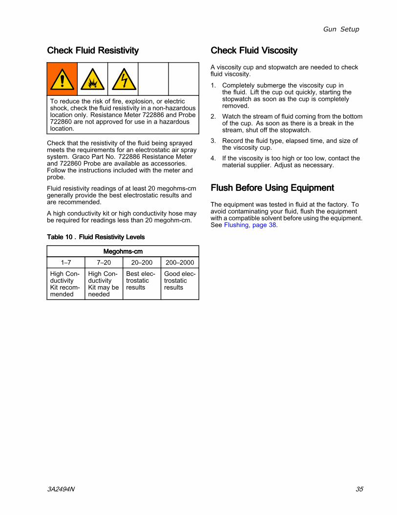
CheckCheckCheck FluidFluidFluid ResistivityResistivityResistivity
To reduce the risk of fire, explosion, or electricshock, check the fluid resistivity in a non-hazardouslocation only. Resistance Meter 722886 and Probe722860 are not approved for use in a hazardouslocation.
Check that the resistivity of the fluid being sprayedmeets the requirements for an electrostatic air spraysystem. Graco Part No. 722886 Resistance Meterand 722860 Probe are available as accessories.Follow the instructions included with the meter andprobe.
Fluid resistivity readings of at least 20 megohms-cmgenerally provide the best electrostatic results andare recommended.
A high conductivity kit or high conductivity hose maybe required for readings less than 20 megohm-cm.
TableTableTable 101010 ... FluidFluidFluid ResistivityResistivityResistivity LevelsLevelsLevels
MegohmsMegohmsMegohms---cmcmcm
1–7 7–20 20–200 200–2000
High Con-ductivityKit recom-mended
High Con-ductivityKit may beneeded
Best elec-trostaticresults
Good elec-trostaticresults
CheckCheckCheck FluidFluidFluid ViscosityViscosityViscosity
A viscosity cup and stopwatch are needed to checkfluid viscosity.
1. Completely submerge the viscosity cup inthe fluid. Lift the cup out quickly, starting thestopwatch as soon as the cup is completelyremoved.
2. Watch the stream of fluid coming from the bottomof the cup. As soon as there is a break in thestream, shut off the stopwatch.
3. Record the fluid type, elapsed time, and size ofthe viscosity cup.
4. If the viscosity is too high or too low, contact thematerial supplier. Adjust as necessary.
FlushFlushFlush BeforeBeforeBefore UsingUsingUsing EquipmentEquipmentEquipment
The equipment was tested in fluid at the factory. Toavoid contaminating your fluid, flush the equipmentwith a compatible solvent before using the equipment.See Flushing, page 38.
3A2494N 35

Operation
OperationOperationOperation
PressurePressurePressure ReliefReliefRelief ProcedureProcedureProcedure
This equipment stays pressurized until pressureis manually relieved. To help prevent seriousinjury from pressurized fluid, such as splashing,follow the Pressure Relief Procedure when youstop spraying and before cleaning, checking, orservicing the equipment.
1. Turn OFF (O) the ES On/Off switch.
2. Turn off the air bleed valves to the fluid sourceand to the gun.
3. Trigger the gun into a grounded metal wastecontainer to relieve the fluid pressure.
4. Open the pump drain valve, having a wastecontainer ready to catch the drainage. Leavethe pump drain valve open until you are readyto spray again.
5. If the nozzle or hose is completely clogged orpressure is not fully relieved, slowly loosen thehose end coupling. Now clear the nozzle or hose.
36 3A2494N

Operation
StartupStartupStartup
Follow all steps under Gun Setup Procedure, page 25.
Before operating the system, check the following listdaily to ensure safe, efficient operation.
• All operators are properly trained to safely operatean electrostatic air spray system as instructed inthis manual.
• All operators are trained in thePressure Relief Procedure, page 36.
• The warning sign provided with the gun is mountedin the spray area where it can be easily seen andread by all operators.
• The system is thoroughly grounded and theoperator and all persons entering the spray areaare properly grounded. See Grounding, page 21.
• The condition of the gun’s electricalcomponents has been checked as instructed inElectrical Tests, page 42.
• Ventilation fans are operating properly.• Workpiece hangers are clean and grounded.• All debris (including flammable fluids and rags) isremoved from the spray area.
• All flammable fluids in the spray booth are inapproved, grounded containers.
• All conductive objects in the spray area areelectrically grounded and the floor of the sprayarea is electrically conductive and grounded.
ShutdownShutdownShutdown
To reduce the risk of an injury, follow thePressure Relief Procedure, page 36 whenever youare instructed to relieve the pressure.
1. Flush the gun. Follow the steps inFlushing, page 38.
2. Follow the Pressure Relief Procedure, page 36.3. Hang the gun from its hook, with the nozzle
pointing down.
3A2494N 37

Maintenance
MaintenanceMaintenanceMaintenance
To reduce the risk of an injury, follow thePressure Relief Procedure, page 36, wheneveryou are instructed to relieve the pressure.
DailyDailyDaily CareCareCare andandand CleaningCleaningCleaning ChecklistChecklistChecklist
Check the following list daily upon completion ofequipment usage.
⃞ Flush the gun. See Flushing, page 38.⃞ Clean the fluid and air line filters.⃞ Clean the outside of the gun. See
Clean the Gun Daily, page 40.⃞ Clean the air cap and fluid nozzle daily,
at a minimum. Some applications requiremore frequent cleaning. Replace the spraytip and air cap if they are damaged. SeeClean the Gun Daily, page 40.
⃞ Check the electrode and replaceif broken or damaged. SeeElectrode Replacement, page 49.
⃞ Check for fluid leakage from the gun and fluidhoses. Tighten fittings or replace equipmentas needed.
⃞ Check electrical grounding. SeeCheck Gun Electrical Grounding, page 34.
FlushingFlushingFlushing
• Flush before changing fluids, before fluid can dryin the equipment, at the end of the day, beforestoring, and before repairing equipment.
• Flush at the lowest pressure possible. Checkconnectors for leaks and tighten as necessary.
• Flush with a fluid that is compatible with the fluidbeing dispensed and the equipment wetted parts.
To reduce the risk of fire, explosion, or electricshock:
• Turn OFF (O) the ES On-Off switch beforeflushing the gun.
• Always ground equipment and waste containers.• Flush equipment only in a well-ventilated area.• Use only Group IIA flushing materials.Non-ignitable fluids are preferred.
• To avoid static sparking and injury fromsplashing, always flush at the lowest possiblepressure.
NOTICENOTICENOTICEDo not use methylene chloride as a flushing orcleaning solvent with this gun as it will damagenylon components.
1. Turn OFF (O) the ES On-Off switch.
38 3A2494N

Maintenance
2. Follow the Pressure Relief Procedure, page 36.
3. Change the fluid source to solvent, or disconnectthe fluid line and connect a solvent supply lineto the gun.
4. Point the gun into a grounded metal pail. Flushuntil clean solvent flows from the gun.
5. Follow the Pressure Relief Procedure, page 36.
6. Shut off or disconnect the solvent line.7. Hang the gun from its hook, with the nozzle
pointing down.
8. When ready to spray again, reconnectthe fluid supply line. Follow theGun Setup Procedure, page 25.
3A2494N 39
Maintenance
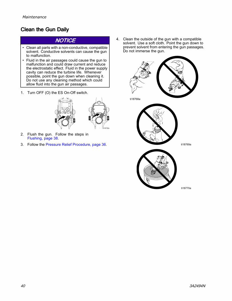
CleanCleanClean thethethe GunGunGun DailyDailyDaily
NOTICENOTICENOTICE• Clean all parts with a non-conductive, compatiblesolvent. Conductive solvents can cause the gunto malfunction.
• Fluid in the air passages could cause the gun tomalfunction and could draw current and reducethe electrostatic effect. Fluid in the power supplycavity can reduce the turbine life. Wheneverpossible, point the gun down when cleaning it.Do not use any cleaning method which couldallow fluid into the gun air passages.
1. Turn OFF (O) the ES On-Off switch.
2. Flush the gun. Follow the steps inFlushing, page 38.
3. Follow the Pressure Relief Procedure, page 36.
4. Clean the outside of the gun with a compatiblesolvent. Use a soft cloth. Point the gun down toprevent solvent from entering the gun passages.Do not immerse the gun.
40 3A2494N

Maintenance
5. Clean the air cap.
a. Remove the air cap.
b. Clean the air cap, retaining ring, and nozzlewith a soft brush and compatible solvent.
c. If necessary, use a toothpick or other softtool to clean the air cap holes. Do not usemetal tools.
d. Reinstall the air cap. Tighten securely.
DailyDailyDaily SystemSystemSystem CareCareCare1. Follow the Pressure Relief Procedure, page 36.2. Clean the fluid and air filters.3. Check for fluid leaks. Tighten all fittings.
4. Clean workpiece hangers. Use non-sparkingtools.
5. Check the movement of the trigger and valves.Lubricate if necessary.
6. Check Gun Electrical Grounding, page 34.7. Hang the gun from its hook, with the nozzle
pointing down.
3A2494N 41
Electrical Tests
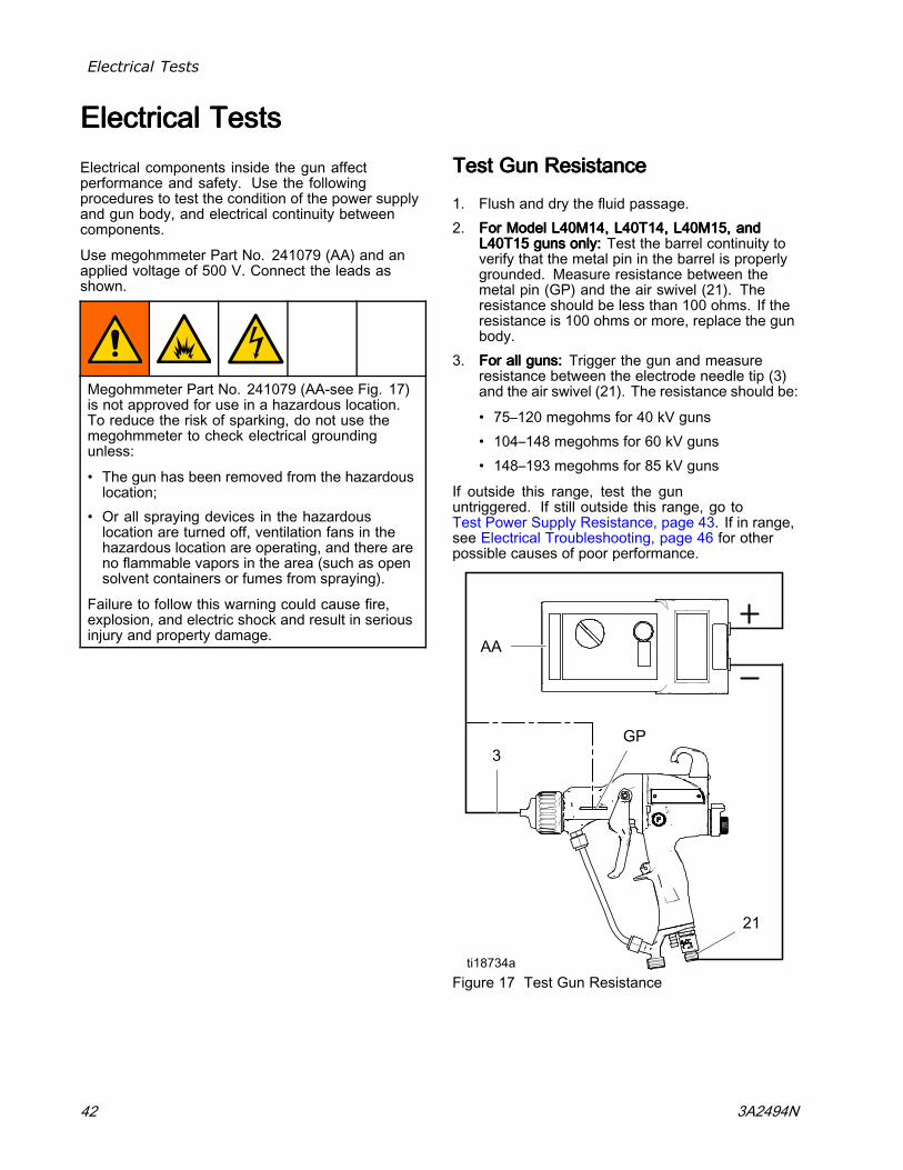
ElectricalElectricalElectrical TestsTestsTestsElectrical components inside the gun affectperformance and safety. Use the followingprocedures to test the condition of the power supplyand gun body, and electrical continuity betweencomponents.
Use megohmmeter Part No. 241079 (AA) and anapplied voltage of 500 V. Connect the leads asshown.
Megohmmeter Part No. 241079 (AA-see Fig. 17)is not approved for use in a hazardous location.To reduce the risk of sparking, do not use themegohmmeter to check electrical groundingunless:
• The gun has been removed from the hazardouslocation;
• Or all spraying devices in the hazardouslocation are turned off, ventilation fans in thehazardous location are operating, and there areno flammable vapors in the area (such as opensolvent containers or fumes from spraying).
Failure to follow this warning could cause fire,explosion, and electric shock and result in seriousinjury and property damage.
TestTestTest GunGunGun ResistanceResistanceResistance
1. Flush and dry the fluid passage.2. ForForFor ModelModelModel L40M14,L40M14,L40M14, L40T14,L40T14,L40T14, L40M15,L40M15,L40M15, andandand
L40T15L40T15L40T15 gunsgunsguns only:only:only: Test the barrel continuity toverify that the metal pin in the barrel is properlygrounded. Measure resistance between themetal pin (GP) and the air swivel (21). Theresistance should be less than 100 ohms. If theresistance is 100 ohms or more, replace the gunbody.
3. ForForFor allallall guns:guns:guns: Trigger the gun and measureresistance between the electrode needle tip (3)and the air swivel (21). The resistance should be:
• 75–120 megohms for 40 kV guns• 104–148 megohms for 60 kV guns• 148–193 megohms for 85 kV guns
If outside this range, test the gununtriggered. If still outside this range, go toTest Power Supply Resistance, page 43. If in range,see Electrical Troubleshooting, page 46 for otherpossible causes of poor performance.
Figure 17 Test Gun Resistance
42 3A2494N

Electrical Tests
TestTestTest PowerPowerPower SupplySupplySupply ResistanceResistanceResistance
1. Remove the power supply (11). Follow the stepsin Power Supply Removal and Replacement,page 53.
2. Remove the alternator (15)from the power supply. SeeAlternator Removal and Replacement, page 54.
3. Measure resistance from the power supply'sground strips (EE) to the spring (11a). Theresistance should be:
• 60–85 megohms for 40 kV guns• 86–110 megohms for 60 kV guns• 130–160 megohms for 85 kV guns
4. If outside this range, replace thepower supply. If in range, go toTest Electrode Resistance, page 43.
5. If you still have problems, refer toElectrical Troubleshooting, page 46 forother possible causes of poor performance, orcontact your Graco distributor.
6. Be sure the spring (11a) is in place beforereinstalling the power supply.
Figure 18 Test Power Supply Resistance
TestTestTest ElectrodeElectrodeElectrode ResistanceResistanceResistance
Remove the electrode (3). SeeElectrode Replacement, page 49. Measurethe resistance between the contact (HH) and theelectrode wire (GG). The resistance should be 8-30megohms. If out of range, replace the electrode.
NOTE:NOTE:NOTE: If the gun resistance is still out of range aftertesting the power supply and electrode:
• Check that the conductive o-ring (4a) is makingcontact with the barrel pin.
• Check that the power supply spring (11a) is makingcontact with the barrel pin.
Figure 19 Test Electrode Resistance
3A2494N 43

Troubleshooting
TroubleshootingTroubleshootingTroubleshooting
Installing and servicing this equipment requiresaccess to parts which may cause an electric shockor other serious injury if the work is not performedproperly. Do not install or repair this equipmentunless you are trained and qualified.
To reduce the risk of an injury, follow thePressure Relief Procedure, page 36, wheneveryou are instructed to relieve the pressure.
Check all possible remedies in the Troubleshooting Chart before disassembling the gun.
SpraySpraySpray PatternPatternPattern TroubleshootingTroubleshootingTroubleshooting
Some spray pattern problems are caused by the improper balance between air and fluid.
ProblemProblemProblem CauseCauseCause SolutionSolutionSolution
No fluid. Refill supply.
Loose, dirty, damagednozzle/seat.
Clean or replace nozzle. SeeClean the Gun Daily, page 40, orAir Cap and Nozzle Replacement,page 48.
Fluttering or spitting spray.
Air in fluid supply. Check fluid source. Refill.
Improper spray pattern. Damaged or dirty nozzle or air cap. Clean or replace. See Air Cap andNozzle Replacement, page 48.
Fluid buildup on air cap or nozzle. Clean. SeeClean the Gun Daily, page 40.
Fan air pressure too high. Decrease.
Fluid too thin. Increase viscosity.
Fluid pressure too low. Increase.
Fan air pressure too low. Increase.
Fluid too thick. Reduce viscosity.
Too much fluid. Decrease flow.
Did not apply 50% overlap. Overlap strokes 50%.Streaks.
Dirty or damaged air cap. Clean or replace air cap. SeeClean the Gun Daily, page 40, orAir Cap and Nozzle Replacement,page 48.
44 3A2494N

Troubleshooting
GunGunGun OperationOperationOperation TroubleshootingTroubleshootingTroubleshooting
ProblemProblemProblem CauseCauseCause SolutionSolutionSolution
Atomizing air pressure too high. Close restrictor valve part way, ordecrease air pressure as low aspossible; minimum 45 psi (0.32MPa, 3.2 bar) needed at gun forfull voltage.
Excessive spray fog.
Fluid too thin, or fluid flow is toolow.
Increase viscosity or increase fluidflow rate.
Atomizing air pressure too low. Open atomizing air valve more orincrease gun air inlet pressure;use lowest air pressure necessary.
Poorly mixed or filtered fluid. Remix or refilter fluid.
“Orange Peel” finish.
Fluid too thick. Reduce viscosity.
Fluid leaks from the fluid packingarea.
Worn packings or rod. Replace packings. SeePacking Rod Repair, page 50.
Air leaks from the front of the gun. Air valve is not seating properly. Replace air valve. SeeAir Valve Repair, page 60.
Worn or damaged fluid packingrod or electrode.
Replace packing rod (2e)or electrode (3). SeePacking Rod Repair, page 50 orElectrode Replacement, page 49.
Worn fluid nozzle seat. Replace nozzle (4). SeeAir Cap and Nozzle Replacement,page 48.
Loose fluid nozzle. Tighten.
Fluid leakage from the front of thegun.
Damaged nozzle o-ring. Replace o-ring. See Air Cap andNozzle Replacement, page 48.
Low fluid supply. Add fluid if necessary.
Dirty or clogged fluid nozzle. Clean. SeeClean the Gun Daily, page 40.
Gun does not spray.
Closed or damaged fluidadjustment valve.
Open valve, or seeES On-Off and Fluid AdjustmentValve Repair, page 59.
Dirty air cap. Misaligned air cap and fluid nozzle. Clean fluid buildup off air capand fluid nozzle seat. SeeClean the Gun Daily, page 40.
Poor grounding. See Grounding, page 21.Excessive paint wrap back tooperator.
Incorrect distance from gun to part. Should be 8–12 in. (200–300 mm).
3A2494N 45

Troubleshooting
ElectricalElectricalElectrical TroubleshootingTroubleshootingTroubleshooting
ProblemProblemProblem CauseCauseCause SolutionSolutionSolution
ES On/Off switch is OFF (O). Turn ON (I).
Gun air pressure too low (ES indicatoris amber).
Check air pressure to gun; minimum 45psi (0.32 MPa, 3.2 bar) needed at gunfor full voltage.
Atomizing air pressure too high. Decrease.
Incorrect distance from gun to part. Should be 8-12 in. (200-300 mm).
Poorly grounded parts. Resistance must be 1 megohm or less.Clean workpiece hangers.
Faulty gun resistance. See Test Gun Resistance, page 42.
Low fluid resistivity. See Check Fluid Resistivity, page 35.
Fluid leaks from the packing (2c) andcauses a short.
See Packing Rod Repair, page 50.
Poor wrap.
Faulty alternator. See Alternator Removal andReplacement, page 54.
ES On/Off switch is OFF (O). Turn ON (I).ES or Hz indicator is notlit. No power. Check power supply, alterna-
tor, and alternator ribbon cable.See Power Supply Removal andReplacement, page 53 and AlternatorRemoval and Replacement, page 54.
Operator not grounded or is nearungrounded object.
See Grounding, page 21.Operator gets mild shock.
Gun not grounded. See Check Gun ElectricalGrounding, page 34, andTest Gun Resistance, page 42.
Operator gets shock fromworkpiece.
Workpiece not grounded. Resistance must be 1 megohm or less.Clean workpiece hangers.
Gun is too close to the part beingsprayed.
Gun should be 8–12 in. (200–300 mm)from the part.
Check fluid resistivity. See Check Fluid Resistivity, page 35.
Voltage/current displaystays red (Smart gunsonly).
Dirty gun. See Clean the Gun Daily, page 40.
ES or HZ indicator isamber.
Alternator speed is too low. Increase air pressure until indicatoris green. To avoid over-atomization,use the atomizing air restrictor valve toreduce the atomizing air to the air cap.
ES or Hz indicator is red. Alternator speed is too high. Decrease air pressure until indicator isgreen.
Error display appearsand Hz indicator is red(Smart guns only).
Smart module has lost communicationwith the power supply.
Check for good connectionsbetween the Smart Moduleand the power supply. SeeSmart Module Replacement, page 61 a-nd Power Supply Removal andReplacement, page 53.
46 3A2494N

Repair
RepairRepairRepair
PreparePreparePrepare thethethe GunGunGun forforfor ServiceServiceService
Installing and repairing this equipment requiresaccess to parts that may cause electric shock orother serious injury if the work is not performedproperly. Do not install or service this equipmentunless you are trained and qualified.
To reduce the risk of injury, follow the PressureRelief Procedure before checking or servicing anypart of the system and whenever you are instructedto relieve the pressure.
• Check all possible remediesin Troubleshooting, page 44 before disassemblingthe gun.
• Use a vise with padded jaws to prevent damageto plastic parts.
• Lubricate some packing rod parts (2) and certainfluid fittings with dielectric grease (44), as specifiedin the text.
• Lightly lubricate o-rings and seals with non-siliconegrease. Order Part No. 111265 Lubricant. Do notover-lubricate.
• Only use genuine Graco parts. Do not mix or useparts from other Pro Gun models.
• Air Seal Repair Kit 24N789 is available. Thekit must be purchased separately. Kit parts aremarked with an asterisk, for example (6a*).
• Fluid Seal Repair Kit 24N790 is available. Thekit must be purchased separately. Kit parts aremarked with a symbol, for example (2a‡).
1. Flush the gun. Follow the steps inFlushing, page 38.
2. Relieve the pressure. Follow thePressure Relief Procedure, page 36.
3. Disconnect the gun air and fluid lines.4. Remove the gun from the worksite. Repair area
must be clean.
3A2494N 47

Repair
AirAirAir CapCapCap andandand NozzleNozzleNozzle ReplacementReplacementReplacement
NOTICENOTICENOTICETrigger the gun while removing the nozzle to helpdrain the gun and prevent any paint or solvent leftin the gun from entering the air passages.
1. Follow the steps inPrepare the Gun for Service, page 47.
2. Remove the retaining ring (6) and air cap (5).3. Trigger the gun while removing the fluid nozzle
(4) assembly with the multi-tool (41).
The nozzle contact ring (4a) is a conductivecontact ring, not a sealing o-ring. To reducethe risk of sparking or electric shock, do notremove the nozzle contact ring (4a) except toreplace it and never operate the gun withoutthe contact ring in place. Do not replace thecontact ring with anything but a genuine Gracopart.
NOTE:NOTE:NOTE: Use non-silicone grease, Part No.111265, on the small o-ring (4b). Do notover-lubricate. Do not lubricate the conductivecontact ring (4a). Excessive grease can mix withpaint and blemish the finish on the workpiece.
4. Make sure the conductive contact ring (4a) andthe small o-ring (4b) are in place on the nozzle(4). Lightly lubricate the small o-ring (4b).NOTE:NOTE:NOTE: The conductive contact ring (4a) mayshow some wear at the point where it makescontact with the barrel pin. This is normal anddoes not require replacement.
5. Make sure the electrode needle (3) is finger-tight.6. Trigger the gun while installing the fluid nozzle
(4) with the multi-tool (41). Tighten until the fluidnozzle seats in the gun barrel (1/8 to 1/4 turnpast hand-tight).
7. Install the air cap (5) and retaining ring (6). Makesure the u-cup (6a*) is in place with the lips facingforward.
8. Follow the steps in Test Gun Resistance, page 42.
Figure 20 Air Cap and Nozzle Replacement
48 3A2494N

Repair
ElectrodeElectrodeElectrode ReplacementReplacementReplacement
1. Follow the steps inPrepare the Gun for Service, page 47.
2. Remove the air cap and nozzle. SeeAir Cap and Nozzle Replacement, page 48.
3. Unscrew the electrode (3) with the multi-tool (41).4. Apply low-strength (purple) threadlocker to the
electrode and packing rod threads. Install theelectrode finger-tight. Do not overtighten.
5. Install the fluid nozzle and air cap. SeeAir Cap and Nozzle Replacement, page 48.
NOTICENOTICENOTICETo avoid damaging the plastic threads, be verycareful when installing the electrode.
6. Follow the steps in Test Gun Resistance, page 42.
Figure 21 Electrode Replacement
3A2494N 49

Repair
FluidFluidFluid PackingPackingPacking RodRodRod RemovalRemovalRemoval
1. Follow the steps inPrepare the Gun for Service, page 47.
2. Remove the air cap and fluid nozzle. SeeAir Cap and Nozzle Replacement, page 48.
3. Remove the electrode. SeeElectrode Replacement, page 49.
4. Loosen the trigger screws (13) and remove thetrigger (12).
5. Remove the packing rod (2), using the multi-tool(41). Remove the spring (17).
6. Check all parts for wear or damage and replaceif necessary.
Figure 22 Fluid Packing Rod Removal
PackingPackingPacking RodRodRod RepairRepairRepair
NOTE:NOTE:NOTE: You may replace the packing rod as individualparts or as an assembly.
AdjustAdjustAdjust thethethe AirAirAir FlowFlowFlow LeadLeadLead andandand LagLagLag
NOTE:NOTE:NOTE: The gun begins emitting air before the fluidis discharged and the fluid stops before the air flowstops. The packing rod assembly is pre-adjusted atthe factory for proper air lead and lag. Adjust onlyif necessary, as follows.
1. Remove the spring (17) from the nut (2k).2. Use a hex wrench to hold the end of the packing
rod. Turn both adjustment nuts (2j, 2k) out toincrease the lead/lag time for the air flow. Therecommended adjustment is one half turn andnot more than one full turn.
3. Tighten the nuts together to fix them in the newposition.
50 3A2494N

Repair
ReassembleReassembleReassemble thethethe PackingPackingPacking RodRodRod
NOTE:NOTE:NOTE: Before installing the fluid packing rod into thegun barrel, make sure the internal surfaces of thebarrel are clean. Remove any residue with a softbrush or cloth. Check the inside of the barrel formarks from high voltage arcing. If marks are present,replace the barrel.
1. Place the packing nut (2f) and seal (2b‡) on thefluid rod (2e). Flats on the packing nut must facethe back of the fluid rod. The seal o-ring mustface away from the packing nut.
2. Fill the inner cavity of the spacer (2h‡) withdielectric grease (44). Place the spacer on thefluid rod (2e) in the direction shown. Generouslyapply dielectric grease to the outside of thespacer.
3. Place the fluid packing (2c‡) on the packing rod(2e) with its lips facing the front of the rod. Installthe needle packing (2d‡) with the male endtoward the fluid packing, then install the housing(2g) .
4. Lightly tighten the packing nut (2f). The packingnut is properly tightened when there is 3 lb (13.3N) of drag force when sliding the packing housing(2g) assembly along the rod. Tighten or loosenthe packing nut as needed.
5. Install the o-ring (2a‡) on the outside of housing(2g). Lubricate the o-ring with non-siliconegrease, Part No. 111265. Do not over-lubricate.
6. Install the spring (17) against the nut (2j) asshown.
7. Install the packing rod assembly (2) into thegun barrel. Using the multi-tool (41), tighten theassembly until just snug.
8. Install the electrode. SeeElectrode Replacement, page 49, step 4.
9. Install the nozzle and air cap. SeeAir Cap and Nozzle Replacement, page 48,steps 5–7.
10. Install the trigger (12) and screws (13).11. Follow the steps in Test Gun Resistance, page 42.
Figure 23 Packing Rod
3A2494N 51

Repair
BarrelBarrelBarrel RemovalRemovalRemoval
1. Follow the steps inPrepare the Gun for Service, page 47.
2. Carefully loosen the nut (N) from the bracket fluidfitting (20). Pull the tube (T) out of the fitting.Make sure both ferrules (7, 8) and the nut staywith the tube.
3. Loosen the two screws (27).
NOTICENOTICENOTICETo avoid damaging the power supply (11), pullthe gun barrel (1) straight away from the gunhandle (16). If necessary, gently move the gunbarrel from side to side to free it from the gunhandle.
4. Hold the gun handle (16) with one hand and pullthe barrel (1) straight off the handle.
NOTE:NOTE:NOTE: If the power supply remains in the barrel,remove the alternator/power supply assembly fromthe barrel.
Figure 24 Barrel Removal
BarrelBarrelBarrel InstallationInstallationInstallation1. Be sure the gasket (28*) and grounding spring
(18) are in place. Make sure the gasket airholes are aligned properly. Replace the gasket ifdamaged.
2. Make sure the spring (11a) is in place on the tip ofthe power supply (11). LiberallyLiberallyLiberally apply dielectricgrease (44) to the tip of the power supply. Placethe barrel (1) over the power supply and onto thegun handle (16).
3. Tighten the two screws (27) oppositely andevenly (about a half turn past snug or 15–25 in-lb,1.7–2.8 N•m).
NOTICENOTICENOTICETo avoid damaging the gun barrel, do notover-tighten the screws (27).
4. Assemble the fluid tube (T) into the bracket fitting(20). Ensure that the ferrules (7, 8) are in place.Tighten the nut (N) securely onto the fitting.Make sure the top fitting remains tight.
5. Follow the steps in Test Gun Resistance, page 42.
Figure 25 Barrel Installation
52 3A2494N

Repair
PowerPowerPower SupplySupplySupply RemovalRemovalRemoval andandandReplacementReplacementReplacement
• Inspect the gun handle power supply cavity for dirtor moisture. Clean with a clean, dry rag.
• Do not expose gasket (28) to solvents. Replacethe gasket if damaged.
1. Follow the steps inPrepare the Gun for Service, page 47.
2. Follow the steps in Barrel Removal, page 52.
NOTICENOTICENOTICEBe careful when handling the power supply(11) to avoid damaging it.
3. Grasp the power supply (11) with your hand.With a gentle side to side motion, free the powersupply/alternator assembly from the gun handle(16), then carefully pull it straight out. On SmartModels only, disconnect the flexible circuit (24)from the socket at the top of the handle.
4. Inspect the power supply and alternator fordamage.
5. To separate the power supply (11) from thealternator (15), disconnect the 3-wire ribbonconnector (PC) from the power supply. On SmartModels only, disconnect the 6–pin flexible circuit(24) from the power supply. Slide the alternatorup and off the power supply.
6. Follow the steps inTest Power Supply Resistance, page 43.Replace the power supply if necessary.To repair the alternator, seeAlternator Removal and Replacement, page 54.
NOTICENOTICENOTICETo prevent damage to the cable and possibleinterruption of the ground continuity, bend thealternator’s 3-wire ribbon cable (PC) upwardand back, so the bend faces the power supplyand the connector is at the top.
7. Smart models only: connect the 6–pin flexiblecircuit (24) to the power supply.
8. Connect the 3-wire ribbon connector (PC) to thepower supply. Tuck the ribbon forward, underthe power supply. Slide the alternator (15) downonto the power supply (11).
9. Insert the power supply/alternator assembly inthe gun handle (16). Make sure the ground strips(EE) make contact with the handle. On Smartmodels, align the connector of the 6–pin flexiblecircuit (24) with the socket (CS) at the top of thehandle. Push the connector securely into thesocket as you slide the power supply/alternatorassembly into the handle.
Figure 26 Connect Flexible Circuit10. Make sure the gasket (28*), ground spring (18),
and power supply spring (11a) are in place.Assemble the barrel (1) to the handle (16). SeeBarrel Installation, page 52.
11. Follow the steps in Test Gun Resistance, page 42.
Figure 27 Power Supply
3A2494N 53

Repair
AlternatorAlternatorAlternator RemovalRemovalRemoval andandand ReplacementReplacementReplacement
NOTE:NOTE:NOTE: Replace alternator bearings after 2000 hoursof operation. Order Part No. 24N706 Bearing Kit.Parts included in the kit are marked with a symbol (♦).
1. Follow the steps inPrepare the Gun for Service, page 47.
2. Remove the power supply/alternator assemblyand disconnect the alternator. See Power SupplyRemoval and Replacement, page 53.
3. Measure resistance between the two outerterminals of the 3-wire connector (PC); it shouldbe 2.0–6.0 ohms. If outside this range, replacethe alternator coil (15a).
4. Using a flat blade screwdriver, pry the clip (15h)off the housing (15d). Remove the cap (15f),using a thin blade or screwdriver.
5. If necessary, rotate the fan (15e) so its bladesclear the four bearing tabs (T) of the housing(15d).
Figure 28 Fan Orientation
6. Push the fan and coil assembly (15a) out thefront of the housing (15d).
Figure 29 Alternator Cross-Section(Ref. 28♦ is not shown in the figure.)
NOTICENOTICENOTICEDo not scratch or damage the magnet (M) orshaft (S). Do not pinch or damage the 3–wireconnector (PC) when disassembling andreassembling the bearings.
7. Hold the coil assembly (15a) on a workbenchwith the fan end facing up. Using a wide bladescrewdriver, pry the fan (15e) off the shaft (S).
8. Remove the top bearing (15b2).9. Remove the bottom bearing (15b1).10. Install the new bottom bearing (15b1♦) on the
long end of the shaft (S). The flatter side of thebearing must face away from the magnet (M).Install in the coil (15a) so the bearing blades areflush with the surface of the coil.
11. Press the new top bearing (15b2♦) onto the shortend of the shaft so the bearing blades are flushwith the surface of the coil (15a). The flatter sideof the bearing must face away from the coil.
54 3A2494N

Repair
12. Hold the coil assembly (15a) on a workbenchwith the fan end facing up. Press the fan (15e♦)onto the long end of the shaft (S). The fan bladesmust be oriented as shown.
13. Carefully press the coil assembly (15a) into thefront of the housing (15d♦) while aligning thepin on the coil with the slot in the housing. The3–wire connector (PC) must be positioned belowthe wider notch (W) of the housing tabs, asshown in Fig. 45. Be sure the coil alignment pins(P) are positioned as shown in Fig. 44.
14. Rotate the fan (15e) so its blades clear the fourbearing tabs (T) at the back of the housing.Ensure that the blades of the bottom bearing(15b1♦) align with the tabs.
15. Seat the coil fully into the housing (15d♦). Securewith the clip (15h♦), ensuring that its tabs engagethe slots in the housing.
16. Ensure that the o-ring (15g) is in place. Installthe cap (15f♦).
17. Install the alternator on the power supply, andinstall both parts in the handle. See PowerSupply Removal and Replacement, page 53.
Figure 30 Alternator
3A2494N 55

Repair
FluidFluidFluid TubeTubeTube RemovalRemovalRemoval andandand ReplacementReplacementReplacement
1. Follow the Pressure Relief Procedure, page 36.2. Remove the nut (22) from the bracket (20).3. Inspect the tube and fittings for damage. Replace
as needed.4. Loosen the fitting (9) to remove the fluid tube
(14) from the barrel (1).5. Optionally, on high conductivity models, the cap
and cover can be removed. Use a long rod downthe center of the coiled tube to force the cap offthe cover, then slide the cover off the coil.
6. Apply dielectric grease (44) to the threads of thefitting (9) and the o-ring (10), and along the insidediameter of the fitting (9). Slide the fitting (9) ontothe fluid tube (14)NOTE:NOTE:NOTE: On 40 kV guns, the o–ring (10★) is notused, and ferrules (7★) and (8★) are part of thetop fitting (9).NOTE:NOTE:NOTE: On 60 kV and 85 kV guns, check that thesleeve (SL) is in place near the top of the fluidtube.
7. Verify that the ferrules (7★) and (8★) are inplace. Push the fluid tube into the barrel inlet andhold it in place while threading the fitting into thebarrel (1). Torque to 25–35 in-lb (2.8–3.9 N•m).
8. With the ferrules (7, 8) seated to the bracket (20),screw the nut (22) securely onto the bracket.Make sure the top fitting remains tight.
Figure 31 Fluid Tube
Figure 32 Fluid Tube, HC Models
56 3A2494N

Repair
FanFanFan AirAirAir AdjustmentAdjustmentAdjustment ValveValveValve RepairRepairRepair
1. Follow the steps inPrepare the Gun for Service, page 47.
2. Place a wrench on the flats of the valve housing(30a) and unscrew the valve from the handle(16).NOTE:NOTE:NOTE: You may replace the valve as anassembly (go to step 9) or replace only the o-ring(steps 3–9).
3. Remove the retaining ring (30d).4. Turn the valve shaft (30b) counterclockwise until
it comes free from the valve housing (30a).5. Inspect the o-ring (30c). Remove if damaged.6. Clean all parts and inspect for wear or damage.
NOTE:NOTE:NOTE: Use non-silicone grease, Part No.111265. Do not over-lubricate.
7. When reassembling the fan air valve (30), lightlylubricate the valve threads and screw the shaft(30b) fully into the housing (30a) until bottomed.Install the o-ring (30c*), lubricate, and unscrewthe valve stem until the o-ring enters the housing.
8. Reassemble the retaining ring (30d). Unscrewthe valve stem from the housing until it is stoppedby the retaining ring.
9. Screw the valve assembly (30) into the gunhandle (16), using a wrench on the flats of thehousing. Torque to 15 in-lb (1.7 N•m).
Figure 33 Fan Air Adjustment Valve
3A2494N 57

Repair
AtomizingAtomizingAtomizing AirAirAir RestrictorRestrictorRestrictor ValveValveValve RepairRepairRepair
1. Follow the steps inPrepare the Gun for Service, page 47.
2. Place a wrench on the flats of the valve housing(29a) and unscrew the valve from the handle(16).NOTE:NOTE:NOTE: You may replace the valve as anassembly (go to step 9) or replace only the o-ring(steps 3–9).
3. Unscrew the valve stem (29e). Remove theretaining ring (29d).
4. Turn the valve body (29b) counterclockwise untilit comes free from the valve housing (29a).
5. Inspect the o-ring (29c). Remove if damaged.6. Clean all parts and inspect for wear or damage.
NOTE:NOTE:NOTE: Use non-silicone grease, Part No.111265. Do not over-lubricate.
7. When reassembling the atomizing air restrictorvalve (29), lightly lubricate the o-ring (29c) andpush the valve body (29b) fully into the housing(29a) until bottomed.
8. Reassemble the retaining ring (29d). Thread thevalve stem (29e) halfway into the valve body(29b).
9. Align the slot (S) in the valve stem with the rib (R)in the gun handle. Screw the valve assembly (29)into the gun handle (16), using a wrench on theflats of the housing. Torque to 15 in-lb (1.7 N•m).
NOTE:NOTE:NOTE: If the atomizing air restrictor valve is notdesired, install the supplied plug (42).
Figure 34 Atomizing Air Restrictor Valve
Figure 35 Align Valve Stem
58 3A2494N

Repair
ESESES OnOnOn---OffOffOff andandand FluidFluidFluid AdjustmentAdjustmentAdjustment ValveValveValve RepairRepairRepair
1. Follow the steps inPrepare the Gun for Service, page 47.
2. Loosen the captive screw (26p). Remove thevalve (26) from the handle.
3. Lubricate the o-rings (26b* and 26m*) withnon-silicone grease, Part No. 111265. Do notover-lubricate.NOTE:NOTE:NOTE: Do not over-lubricate parts. Excessivelubricant on the o-rings can be pushed into thegun air passage and blemish the finish on theworkpiece.
4. Clean and inspect parts for damage. Replaceif necessary.NOTE:NOTE:NOTE: The protrusion on the retainer plate (26h)must point upward.
5. Reinstall the valve. Torque the screw (27) to15-25 in-lb (1.7-2.8 N•m).
Figure 36 ES On-Off Valve Repair, 24N630 and26A160
Figure 37 ES On-Off Valve Repair, 24N632
3A2494N 59

Repair
AirAirAir ValveValveValve RepairRepairRepair
1. Follow the steps inPrepare the Gun for Service, page 47.
2. Follow the steps in Barrel Removal, page 52.3. Remove the screws (13) and trigger (12).4. Remove the ES On-Off Valve. See ES On-Off
and Fluid Adjustment Valve Repair, page 59,steps 1 and 2.
5. Remove the spring (34).6. Push on the front of the air valve shaft to force it
out the back of the handle. Inspect the rubberseal (23a*) and replace if damaged.
7. Inspect the u-cup (35). Do not remove the u-cupunless damaged. If removed, install the new onewith its lips facing into the gun handle (16). Placethe u-cup on the shaft of the air valve to help seatit in the gun handle.
Figure 38 Install U-Cup
8. Install the air valve (23) and spring (34) into thegun handle (16).
9. Install the ES On-Off Valve. See ES On-Off andFluid Adjustment Valve Repair, page 59, steps3 and 5.
10. Install the trigger (12) and screws (13).11. Follow the steps in Barrel Installation, page 52.
Figure 39 Air Valve
60 3A2494N

Repair
SmartSmartSmart ModuleModuleModule ReplacementReplacementReplacement
If the Error display appears, the Smart Module haslost communication with the power supply. Check forgood connections between the Smart Module andthe power supply.
If the module’s LEDs are not lighting, replace themodule.
1. Follow the steps inPrepare the Gun for Service, page 47.
2. Remove the pivot screw (31e), o-ring (31f), andES HI/LO switch (31c) at the bottom left corner ofthe Smart Module cartridge (31a).
3. Remove the remaining three screws (31d) fromthe cartridge.
4. Pull the Smart Module out the back of the gun.Disconnect the ribbon cable (RC) from theconnector (GC) in the gun handle.
5. Remove the gasket (31b).6. Install a new gasket (31b) on the new cartridge
(31a). Make sure the notched corners of thegasket are at the top.
7. Align the module’s ribbon cable (RC) withthe gun’s cable (GC) and slide them securelytogether, as shown. Tuck the connected cablesinto the recess of the gun handle. Install themodule flush to the back of the gun handle.
8. Install the pivot screw (31e), o-ring (31f), andES HI/LO switch in the bottom left corner of thecartridge (31a).
9. Install the three remaining screws (31d). Torqueto 7–9 in-lb (0.8–1.0 N•m).
Figure 40 Smart Module
Figure 41 Align Ribbon Cables
3A2494N 61
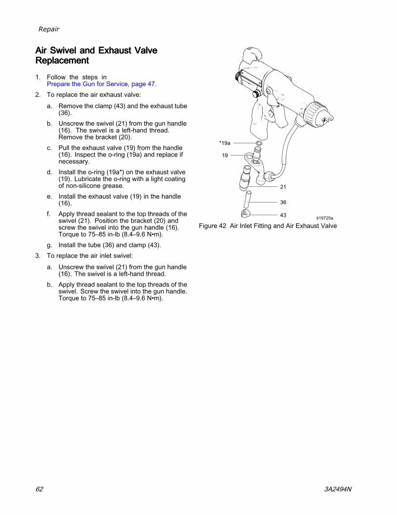
Repair
AirAirAir SwivelSwivelSwivel andandand ExhaustExhaustExhaust ValveValveValveReplacementReplacementReplacement
1. Follow the steps inPrepare the Gun for Service, page 47.
2. To replace the air exhaust valve:
a. Remove the clamp (43) and the exhaust tube(36).
b. Unscrew the swivel (21) from the gun handle(16). The swivel is a left-hand thread.Remove the bracket (20).
c. Pull the exhaust valve (19) from the handle(16). Inspect the o-ring (19a) and replace ifnecessary.
d. Install the o-ring (19a*) on the exhaust valve(19). Lubricate the o-ring with a light coatingof non-silicone grease.
e. Install the exhaust valve (19) in the handle(16).
f. Apply thread sealant to the top threads of theswivel (21). Position the bracket (20) andscrew the swivel into the gun handle (16).Torque to 75–85 in-lb (8.4–9.6 N•m).
g. Install the tube (36) and clamp (43).3. To replace the air inlet swivel:
a. Unscrew the swivel (21) from the gun handle(16). The swivel is a left-hand thread.
b. Apply thread sealant to the top threads of theswivel. Screw the swivel into the gun handle.Torque to 75–85 in-lb (8.4–9.6 N•m).
Figure 42 Air Inlet Fitting and Air Exhaust Valve
62 3A2494N

Parts
PartsPartsParts
GunGunGun ModelsModelsModels withwithwith StandardStandardStandard DisplayDisplayDisplay
1 Torque to 20 in-lb (2 N•m).
3A2494N 63

Parts
GunGunGun ModelsModelsModels withwithwith StandardStandardStandard DisplayDisplayDisplay
To identify components, see Models, page 3 .
Ref.Ref.Ref.No.No.No.
PartPartPart No.No.No. DescriptionDescriptionDescription QtyQtyQty
24N665 BODY, gun; 40 kV gun 1
24N666 BODY, gun; 60 kV gun 1
24N667 BODY, gun; 85 kV gun 1
1■
24N668 BODY, gun; 40 kV booster gun 1
2 See Packing Rod Assembly, page 69 1
See Electrode Selection Chart, page 86
24N651 ELECTRODE, standard 1
24N704 ELECTRODE, high wear 1
3
25N856 ELECTRODE, short 1
4 NOZZLE; includes 4a and 4b. SeeFluid Nozzle Selection Chart, page 77.
4a 24N645 O-RING, conductive 1
4b 111507 O-RING; fluoroelastomer 1
5 See Air Cap Selection Guide, page 80.
6 24N644 RING, retainer; includes 6a 1
6a* 198307 PACKING, u-cup; UHMWPE 1
111286 FERRULE, front; 40 kV gun 17‡★
111286 FERRULE, front; 60 and 85 kVguns
2
111285 FERRULE, back; 40 kV gun 18‡★
111285 FERRULE, back; 60 and 85 kVguns
2
24N656 FITTING, fluid; 40 kV gun 1
24N657 FITTING, fluid; 60 kV gun 1
24N658 FITTING, fluid; 85 kV gun 1
25N852 FITTING, fluid; 60 kV gun, HCfluid tube
1
9
25N851 FITTING, fluid; 85 kV gun, HCfluid tube
1
10★ 102982 PACKING, o-ring; 60 and 85kV guns only
1
24N659 POWER SUPPLY, 40 kV gun 1
24N660 POWER SUPPLY, 60 kV gun 1
11
24N661 POWER SUPPLY, 85 kV gun 1
11a 24N979 SPRING 1
12 24N663 TRIGGER; includes item 13 1
13 24A445 SCREW, trigger; package of 2 1
Ref.Ref.Ref.No.No.No.
PartPartPart No.No.No. DescriptionDescriptionDescription QtyQtyQty
24N695 TUBE, fluid, STD; 40 kV gun 1
24N696 TUBE, fluid, STD, with sleeve;60 kV gun
1
24N697 TUBE, fluid, STD, with sleeve;85 kV gun
1
25N844 TUBE, fluid; HC, 40 kV gun withcover; includes 7,8,9,10,22;see High Conductivity FluidTube Assembly, page 76.
1
25N843 TUBE, fluid; HC, 60 kV gun withcover; includes 7,8,9,10,22;see High Conductivity FluidTube Assembly, page 76.
1
14
25N842 TUBE, fluid; HC, 85 kV gun withcover; includes 7,8,9,10,22;see High Conductivity FluidTube Assembly, page 76.
1
15 24N664 SeeAlternator Assembly, page 70
1
24N751 HANDLE; 40 kV gun 1
24N752 HANDLE; 60 kV gun 1
16
24N753 HANDLE; 85 kV gun 1
17 185111 SPRING, compression 1
18 197624 SPRING, compression 1
19 249323 VALVE, exhaust 1
19a* 112085 O-RING 1
20 24N741 BRACKET 1
21 24N626 SWIVEL, air inlet; M12 x 1/4npsm(m); left-hand thread
1
22 24N698 NUT 1
23 24N633 VALVE, air 1
23a* 276733 SEAL, air valve 1
See ES On-Off and Fluid Adjustment Valve,page 71
24N630 VALVE, ES On/Off and FluidAdjustment Valve; for allmodels except as noted
1
26A160 VALVE, ES On-Off with AirRestrictor and Fluid AdjustmentValve; for High Air Flow gunmodels
1
26
24N632 VALVE, ES On-Off and FixedFluid Valve; for Fixed FluidFlow models
1
64 3A2494N

Parts
Ref.Ref.Ref.No.No.No.
PartPartPart No.No.No. DescriptionDescriptionDescription QtyQtyQty
27 24N740 SCREW, hex socket; sst;package of 2
1
28* 25N921 GASKET, barrel 1
See Atomizing Air Restrictor Valve Assembly,page 72
24T304 VALVE, air restrictor; for allother guns
1
29
24N733 VALVE, air restrictor; forL60T11
1
See Fan Air Adjustment Valve Assembly, page 72
24N634 VALVE, fan air; for all otherguns
1
24N732 VALVE, fan air; for L60T11 1
30
25N919 VALVE, fan air; quick adjustwith spring return
1
34 185116 SPRING, compression 1
35* 188749 PACKING, u-cup 1
36 185103 TUBE, exhaust; 1/4 in. (6 mm)ID (shipped loose)
1
40 107460 TOOL, wrench, ball end; 4 mm(shipped loose)
1
Ref.Ref.Ref.No.No.No.
PartPartPart No.No.No. DescriptionDescriptionDescription QtyQtyQty
41 276741 MULTI-TOOL (shipped loose) 1
42 24N786 PLUG, restrictor (shippedloose; for use instead of item29)
1
43 110231 CLAMP, exhaust tube (shippedloose)
1
44 116553 GREASE, dielectric; 1 oz (30ml) tube (not shown)
1
45 117824 GLOVE, conductive, medium;package of 12; also availablein small (117823) and large(117825)
1
24N603 COVER, gun, 40 and 60 kVguns; package of 10
146
24N604 COVER, gun, 85 kV guns;package of 10
1
47▲ 179791 TAG, warning (not shown) 1
48▲ 16P802 SIGN, warning (not shown) 1
50 24N783 HOOK; includes screw 1
▲ Replacement Danger and Warning labels, tags, andcards are available at no cost.
* These parts are included in Air Seal Repair Kit 24N789(purchase separately).
‡ These parts are included in Fluid Seal Repair Kit 24N790(purchase separately).
■ Gun bodies (Ref. 1) include the barrel gasket (Ref. 28).
NOTE:NOTE:NOTE: On 40 kV guns, the o–ring (10★) is not used, andferrules (7★) and (8★) are part of the top fitting (9).
3A2494N 65
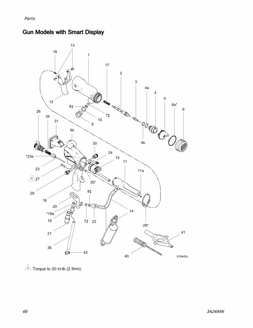
Parts
GunGunGun ModelsModelsModels withwithwith SmartSmartSmart DisplayDisplayDisplay
1 Torque to 20 in-lb (2 N•m).
66 3A2494N

Parts
GunGunGun ModelsModelsModels withwithwith SmartSmartSmart DisplayDisplayDisplay
To identify components, see Models, page 3 .
Ref.Ref.Ref.No.No.No.
PartPartPart No.No.No. DescriptionDescriptionDescription QtyQtyQty
24N665 BODY, gun; 40 kV gun 1
24N666 BODY, gun; 60 kV gun 1
24N667 BODY, gun; 85 kV gun 1
1■
24N668 BODY, gun; 40 kV booster gun 1
2 See Packing Rod Assembly, page 69 1
See Electrode Selection Chart, page 86
24N651 ELECTRODE, standard 1
3
24N704 ELECTRODE, high wear 1
4 NOZZLE; includes 4a and 4b. SeeFluid Nozzle Selection Chart, page 77.
4a 24N645 O-RING, conductive 1
4b 111507 O-RING; fluoroelastomer 1
5 AIR CAP; see Air Cap Selection Guide, page 80
6 24N644 RING, retainer; includes 6a 1
6a* 198307 PACKING, u-cup; UHMWPE 1
7‡ 111286 FERRULE, front 2
8‡ 111285 FERRULE, back 2
24N656 FITTING, fluid; 40 kV gun 1
24N657 FITTING, fluid; 60 kV gun 1
24N658 FITTING, fluid; 85 kV gun 1
25N852 FITTING, fluid; 60 kV gun, HCfluid tube
1
9
25N851 FITTING, fluid; 85 kV gun, HCfluid tube
1
10 102982 PACKING, o-ring 1
24N659 POWER SUPPLY, 40 kV gun 1
24N660 POWER SUPPLY, 60 kV gun 1
11
24N661 POWER SUPPLY, 85 kV gun 1
11a 24N979 SPRING 1
12 24N663 TRIGGER; includes item 13 1
13 24A445 SCREW, trigger; package of 2 1
Ref.Ref.Ref.No.No.No.
PartPartPart No.No.No. DescriptionDescriptionDescription QtyQtyQty
See High Conductivity Fluid Tube Assembly,page 76
24N695 TUBE, fluid, STD; 40 kV gun 1
24N696 TUBE, fluid, STD, with sleeve;60 kV gun
1
24N697 TUBE, fluid, STD, with sleeve;85 kV gun
1
25N844 TUBE, fluid; HC, 40 kV gun withcover; includes 7,8,9,10,22;see High Conductivity FluidTube Assembly, page 76.
1
25N843 TUBE, fluid; HC, 60 kV gun withcover; includes 7,8,9,10,22;see High Conductivity FluidTube Assembly, page 76.
1
14
25N842 TUBE, fluid; HC, 85 kV gun withcover; includes 7,8,9,10,22;see High Conductivity FluidTube Assembly, page 76.
1
15 24N664 SeeAlternator Assembly, page 70
1
25N850 HANDLE, smart; 40 kV gun 1
24N754 HANDLE, smart; 60 kV gun 1
16
24N755 HANDLE, smart; 85 kV gun 1
17 185111 SPRING, compression 1
18 197624 SPRING, compression 1
19 249323 VALVE, exhaust 1
19a* 112085 O-RING 1
20 24N741 BRACKET 1
21 24N626 SWIVEL, air inlet; M12 x 1/4npsm(m); left-hand thread
1
22 24N698 NUT 1
23 24N633 VALVE, air 1
23a* 276733 SEAL, air valve 1
24 245265 CIRCUIT, flexible 1
24N630 See ES On-Off and FluidAdjustment Valve, page 71
126
26A160 See ES On-Off and FluidAdjustment Valve, page 71
1
27 24N740 SCREW, hex socket; sst;package of 2
1
28* 25N921 GASKET, barrel 1
3A2494N 67

Parts
Ref.Ref.Ref.No.No.No.
PartPartPart No.No.No. DescriptionDescriptionDescription QtyQtyQty
29 24T304 See Atomizing Air RestrictorValve Assembly, page 72
1
30 24N634 See Fan Air Adjustment ValveAssembly, page 72
1
31 24N756 See Smart Module Assembly,page 73
1
34 185116 SPRING, compression 1
35* 188749 PACKING, u-cup 1
36 185103 TUBE, exhaust; 1/4 in. (6 mm)ID (shipped loose)
1
40 107460 TOOL, wrench, ball end; 4 mm(shipped loose)
1
41 276741 MULTI-TOOL (shipped loose) 1
42 24N786 PLUG, restrictor (shippedloose; for use instead of item29)
1
Ref.Ref.Ref.No.No.No.
PartPartPart No.No.No. DescriptionDescriptionDescription QtyQtyQty
43 110231 CLAMP, exhaust tube 1
44 116553 GREASE, dielectric; 1 oz (30ml) tube (not shown)
1
45 117824 GLOVE, conductive, medium;package of 12; also availablein small (117823) and large(117825)
1
24N603 COVER, gun, 60 kV guns;package of 10
146
24N604 COVER, gun, 85 kV guns;package of 10
1
47▲ 179791 TAG, warning (not shown) 1
48▲ 16P802 SIGN, warning (not shown) 1
50 24N783 HOOK; includes screw 1
▲ Replacement Danger and Warning labels, tags, andcards are available at no cost.
* These parts are included in Air Seal Repair Kit 24N789(purchase separately).
‡ These parts are included in Fluid Seal Repair Kit 24N790(purchase separately).
■ Gun bodies (Ref. 1) include the barrel gasket (Ref. 28).
68 3A2494N

Parts
PackingPackingPacking RodRodRod AssemblyAssemblyAssembly
PartPartPart No.No.No. 24N65324N65324N653 404040 kVkVkV PackingPackingPacking RodRodRod AssemblyAssemblyAssemblyIncludes items 2a-2kPartPartPart No.No.No. 24N65424N65424N654 606060 kVkVkV PackingPackingPacking RodRodRod AssemblyAssemblyAssemblyIncludes items 2a-2kPartPartPart No.No.No. 24N65524N65524N655 858585 kVkVkV PackingPackingPacking RodRodRod AssemblyAssemblyAssemblyIncludes items 2a-2k
Ref.Ref.Ref.No.No.No.
PartPartPart No.No.No. DescriptionDescriptionDescription QtyQtyQty
2a‡ 111316 O-RING 1
2b‡ 116905 SEAL 1
2c‡ 178409 PACKING, fluid 1
2d‡ 178763 PACKING, needle 1
24N701 ROD, packing, 40 kV guns(includes items 2j and 2k)
1
24N702 ROD, packing, 60 kV guns(includes items 2j and 2k)
1
2e
24N703 ROD, packing, 85 kV guns(includes items 2j and 2k)
1
Ref.Ref.Ref.No.No.No.
PartPartPart No.No.No. DescriptionDescriptionDescription QtyQtyQty
2f 197641 NUT, packing 1
2g 185495 HOUSING, packing 1
2h‡ 186069 SPACER, packing 1
2j◆ — —— NUT, trigger adjustment (partof item 2e)
1
2k◆ — —— NUT, trigger adjustment (partof item 2e)
1
‡ These parts are included in Fluid Seal Repair Kit24N790 (purchase separately).
◆ These parts are included in Trigger Adjustment NutKit 24N700 (purchase separately).
Parts labeled — —— are not available separately.
3A2494N 69

Parts
AlternatorAlternatorAlternator AssemblyAssemblyAssembly
PartPartPart No.No.No. 24N66424N66424N664 AlternatorAlternatorAlternator AssemblyAssemblyAssembly
Ref.Ref.Ref.No.No.No.
PartPartPartNo.No.No.
DescriptionDescriptionDescription QtyQtyQty
15a 24N705 COIL, alternator 1
15b♦ 24N706 BEARING KIT (includes twobearings, item 15d housing,item 15e fan, item 15f cap,and one item 15h clip)
1
15c 24Y264 SHAFT KIT (includes shaftand magnet)
1
15d♦ 24N707 HOUSING; includes item 15f 1
Ref.Ref.Ref.No.No.No.
PartPartPartNo.No.No.
DescriptionDescriptionDescription QtyQtyQty
15e♦ ——— FAN; part of item 15b 1
15f♦ ——— CAP, housing; part of item15d
1
15g* 110073 O-RING 1
15h♦ 24N709 CLIP; package of 5 (one clipincluded with item 15b)
1
28♦* 25N921 GASKET, barrel (not shown) 1
* These parts are included in Air Seal Repair Kit24N789 (purchase separately).
♦ These parts are included in Bearing Kit 24N706(purchase separately).
Parts labeled — —— are not available separately.
70 3A2494N

Parts
ESESES OnOnOn---OffOffOff andandand FluidFluidFluid AdjustmentAdjustmentAdjustment ValveValveValve
PartPartPart No.No.No. 24N63024N63024N630 ESESES On-OffOn-OffOn-Off andandand FluidFluidFluid AdjustmentAdjustmentAdjustmentValveValveValvePartPartPart No.No.No. 26A16026A16026A160 ESESES On-OffOn-OffOn-Off withwithwith AirAirAir RestrictorRestrictorRestrictor andandandFluidFluidFluid AdjustmentAdjustmentAdjustment ValveValveValve
PartPartPart No.No.No. 24N63224N63224N632 ESESES On-OffOn-OffOn-Off andandand FixedFixedFixed FluidFluidFluid ValveValveValve
Ref.Ref.Ref.No.No.No.
PartPartPart No.No.No. DescriptionDescriptionDescription QtyQtyQty
26a — — — HOUSING, valve; black formodels 24N630 and 24N632,blue for restricted model26A160
1
26b* 15D371 O-RING 2
26c — — — PISTON, valve 1
24N649 LEVER, ES on-off; includes26g; models 24N630 and26A160
126f
24N650 LEVER, ES on-off; includes26g; model 24N632
1
26g GC2081 SCREW, set, socket head 2
26h 24N631 PLATE, retaining 1
24N648 KNOB, adjustment, fluid,black; includes 26g; model24N630
126j
25E767 KNOB, adjustment, fluid; blue;includes 26g; model 26A160
1
26m* 113746 O-RING 1
26p 24N740 SCREW, captive; pack of 2 1
* These parts are included in Air Seal Repair Kit24N789 (purchase separately).
Parts labeled — —— are not available separately.
3A2494N 71

Parts
FanFanFan AirAirAir AdjustmentAdjustmentAdjustment ValveValveValve AssemblyAssemblyAssembly
PartPartPart No.No.No. 24N63424N63424N634 FanFanFan AirAirAir AdjustmentAdjustmentAdjustment ValveValveValve AssemblyAssemblyAssembly(shown)(shown)(shown)
PartPartPart No.No.No. 24N73224N73224N732 FanFanFan AirAirAir AdjustmentAdjustmentAdjustment ValveValveValve AssemblyAssemblyAssembly(for(for(for largelargelarge patternpatternpattern roundroundround spraysprayspray guns,guns,guns, notnotnot shown)shown)shown)
Ref.Ref.Ref.No.No.No.
PartPartPart No.No.No. DescriptionDescriptionDescription QtyQtyQty
30a — —— NUT, valve 1— —— STEM, valve 130b— —— STEM, valve; round spray only 1
30c* 111504 O-RING 1
30d 24N646 RING, retaining; package of 6 1
* These parts are included in Air Seal Repair Kit24N789 (purchase separately).
Parts labeled — —— are not available separately.
AtomizingAtomizingAtomizing AirAirAir RestrictorRestrictorRestrictor ValveValveValveAssemblyAssemblyAssembly
PartPartPart No.No.No. 24T30424T30424T304 AtomizingAtomizingAtomizing AirAirAir RestrictorRestrictorRestrictor ValveValveValveAssemblyAssemblyAssembly (shown)(shown)(shown)
PartPartPart No.No.No. 24N73324N73324N733 AtomizingAtomizingAtomizing AirAirAir RestrictorRestrictorRestrictor ValveValveValveAssemblyAssemblyAssembly (for(for(for largelargelarge patternpatternpattern roundroundround spraysprayspray guns,guns,guns, notnotnotshown)shown)shown)
Ref.Ref.Ref.No.No.No.
PartPartPart No.No.No. DescriptionDescriptionDescription QtyQtyQty
29a — —— HOUSING, valve 1— —— BODY, valve 129b— —— BODY, valve; round spray only 1
29c* 111516 O-RING 1
29d 118907 RING, retaining 1
29e — —— STEM, valve 1
29f — — — KNOB, shaft; round spray only 1
29g — —— SETSCREW, knob; roundspray only
1
* These parts are included in Air Seal Repair Kit24N789 (purchase separately).
Parts labeled — —— are not available separately.
72 3A2494N

Parts
SmartSmartSmart ModuleModuleModule AssemblyAssemblyAssembly
PartPartPart No.No.No. 24N75624N75624N756 SmartSmartSmart ModuleModuleModule AssemblyAssemblyAssembly Ref.Ref.Ref.No.No.No.
PartPartPart No.No.No. DescriptionDescriptionDescription QtyQtyQty
31a — — — CARTRIDGE 1
31b 24P433 GASKET 1
31c 24N787 SWITCH, ES HI/LO 1
31d♦ — —— SCREW 3
31e♦ — —— SCREW, pivot 1
31f 112319 O-RING 1
Parts labeled — —— are not available separately.
♦ These parts are included in Smart Module ScrewKit 24N757 (purchase separately).
3A2494N 73

Parts
RoundRoundRound SpraySpraySpray AssemblyAssemblyAssembly
PartPartPart No.No.No. 24N31824N31824N318 largelargelarge patternpatternpattern
NOTE:NOTE:NOTE: Items marked with a ★ are shown forreference and are not included in the kit.
Ref.Ref.Ref.No.No.No.
PartPartPart No.No.No. DescriptionDescriptionDescription QtyQtyQty
4 24N729 NOZZLE, round spray; in-cludes 4a and 4b. SeeFluid Nozzle Selection Chart,page 77.
1
4a 24N645 O-RING, conductive 14b 111507 O-RING; fluoroelastomer 15 24N731 AIR CAP, round spray. See
Air Cap Selection Guide, page80.
1
29 24N733 ATOMIZING AIRRESTRICTOR VALVE,round spray
1
30 24N732 FAN AIR ADJUSTMENTVALVE, round spray
1
49 24N730 DIFFUSER, round spray 1
74 3A2494N

Parts
PartPartPart No.No.No. 25N83625N83625N836 smallsmallsmall patternpatternpattern
PartPartPart No.No.No. 25N83725N83725N837 mediummediummedium patternpatternpattern
NOTE:NOTE:NOTE: Items marked with a ★ are shown forreference and are not included in the kit.
Ref.Ref.Ref.No.No.No.
PartPartPart No.No.No. DescriptionDescriptionDescription QtyQtyQty
25N838 AIR CAP, inner, small pattern;includes 3a–3c
13
25N839 AIR CAP, inner, mediumpattern; includes 3a–3c
1
25N938 DEFLECTOR, small pattern 13a25N939 DEFLECTOR, medium pattern 1113137 O-RING, small pattern 13b113746 O-RING, medium pattern 1— — — DIFFUSER, small pattern 13c— — — DIFFUSER, medium pattern 1
4 25N835 NOZZLE, round spray;includes 4a–4d
1
4a 24N645 O-RING, conductive 14b 111507 O-RING; fluoroelastomer 14c 117610 O-RING 14d 111516 CONDUCTIVE CONTACT
RING1
25N840 AIR CAP, small pattern 1525N841 AIR CAP, medium pattern 1
6 — — — RETAINING RING 1
3A2494N 75
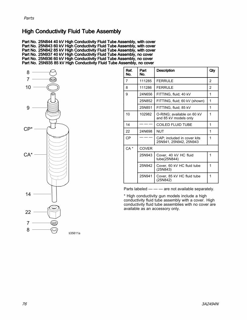
Parts
HighHighHigh ConductivityConductivityConductivity FluidFluidFluid TubeTubeTube AssemblyAssemblyAssembly
PartPartPart No.No.No. 25N84425N84425N844 404040 kVkVkV HighHighHigh ConductivityConductivityConductivity FluidFluidFluid TubeTubeTube Assembly,Assembly,Assembly, withwithwith covercovercoverPartPartPart No.No.No. 25N84325N84325N843 606060 kVkVkV HighHighHigh ConductivityConductivityConductivity FluidFluidFluid TubeTubeTube Assembly,Assembly,Assembly, withwithwith covercovercoverPartPartPart No.No.No. 25N84225N84225N842 858585 kVkVkV HighHighHigh ConductivityConductivityConductivity FluidFluidFluid TubeTubeTube Assembly,Assembly,Assembly, withwithwith covercovercoverPartPartPart No.No.No. 25N93725N93725N937 404040 kVkVkV HighHighHigh ConductivityConductivityConductivity FluidFluidFluid TubeTubeTube Assembly,Assembly,Assembly, nonono covercovercoverPartPartPart No.No.No. 25N93625N93625N936 606060 kVkVkV HighHighHigh ConductivityConductivityConductivity FluidFluidFluid TubeTubeTube Assembly,Assembly,Assembly, nonono covercovercoverPartPartPart No.No.No. 25N93525N93525N935 858585 kVkVkV HighHighHigh ConductivityConductivityConductivity FluidFluidFluid TubeTubeTube Assembly,Assembly,Assembly, nonono covercovercover
Ref.Ref.Ref.No.No.No.
PartPartPartNo.No.No.
DescriptionDescriptionDescription QtyQtyQty
7 111285 FERRULE 2
8 111286 FERRULE 2
24N656 FITTING, fluid; 40 kV 1
25N852 FITTING, fluid; 60 kV (shown) 1
9
25N851 FITTING, fluid; 85 kV 1
10 102982 O-RING; available on 60 kVand 85 kV models only
1
14 — —— COILED FLUID TUBE 1
22 24N698 NUT 1
CP — —— CAP; included in cover kits25N941, 25N942, 25N943
1
COVER
25N943 Cover, 40 kV HC fluidtube(25N844)
1
25N942 Cover, 60 kV HC fluid tube(25N843)
1
CA *
25N941 Cover, 85 kV HC fluid tube(25N842)
1
Parts labeled — —— are not available separately.
* High conductivity gun models include a highconductivity fluid tube assembly with a cover. Highconductivity fluid tube assemblies with no cover areavailable as an accessory only.
76 3A2494N

Fluid Nozzles
FluidFluidFluid NozzlesNozzlesNozzles
FluidFluidFluid NozzleNozzleNozzle SelectionSelectionSelection ChartChartChart
To reduce the risk of an injury, follow the Pressure Relief Procedure, page 36, before removing or installinga fluid nozzle and/or air cap.
FluidFluidFluid NozzleNozzleNozzlePartPartPart No.No.No.
OrificeOrificeOrifice SizeSizeSizemmmmmm (in.)(in.)(in.)
ColorColorColor DescriptionDescriptionDescription
24N619 0.55 (.022) Black
24N613 0.75 (.029) Black
25N895 1.0 (.042) Green
25N896 1.2 (.047) Gray
24N616 1.5 (.055) Black
25N897 1.8 (.070) Brown
24N618 2.0 (.079) Black
StandardStandardStandard nozzlesnozzlesnozzles (STD)(STD)(STD)for standard coatings
25N831 1.0 (.042) Green
25N832 1.2 (.047) Gray
25N833 1.5 (.055) Black
25N834 1.8 (.070) Brown
PrecisionPrecisionPrecision highhighhigh wearwearwear nozzlesnozzlesnozzles (PHW)(PHW)(PHW)with hardened SST seat and damage resistant SST tip; forstandard coatings, abrasives, and metallics
24N620 0.75 (.029)
24N621 1.0 (.042)
24N622 1.2 (.047)
24N623 1.5 (.055)
24N624 1.8 (.070)
24N625 2.0 (.079)
Blue HighHighHigh wearwearwear nozzlesnozzlesnozzles (HW)(HW)(HW)with hardened ceramic seat, for abrasives and metallics
24N729 — — —Black RoundRoundRound spraysprayspray largelargelarge patternpatternpattern nozzlenozzlenozzle
for use with large pattern round spray air cap only
25N835 — — —Black RoundRoundRound SpraySpraySpray mediummediummedium ororor smallsmallsmall patternpatternpattern nozzlenozzlenozzle
for use with medium or small pattern round spray air caps only
3A2494N 77

Fluid Nozzles
FluidFluidFluid NozzleNozzleNozzle PerformancePerformancePerformance ChartsChartsCharts
Use the following procedure to select the proper fluid nozzle for your application.
1. For each fluid nozzle chart, find the point on thegraph corresponding to your desired flow rateand viscosity. Mark the point on each graph witha pencil.
2. The thick vertical line in each graph representsthe target flow rate for that nozzle size. Findthe graph that has the marked point closest tothe thick vertical line. This is the recommendednozzle size for your application. Significantlyexceeding the target flow rate may result inlower spray performance due to excessive fluidvelocity.
3. From the marked point, move across to thevertical scale to find the required fluid pressure.If the required pressure is too high, use the nextlargest nozzle size. If the fluid pressure is too low(< 0.35 bar, 3.5 kPa, 5 psi), use the next smallestnozzle size.
KeyKeyKey tototo FluidFluidFluid NozzleNozzleNozzle PerformancePerformancePerformance ChartsChartsCharts
NOTE:NOTE:NOTE: Fluid pressures are measured at the spray gun inlet.
260 Centipoise Fluid
160 Centipoise Fluid
70 Centipoise Fluid
20 Centipoise Fluid
TableTableTable 111111 ... OrificeOrificeOrifice Size:Size:Size: 0.550.550.55 mmmmmm (0.022(0.022(0.022 in.)in.)in.)
50.5
1.0
1.5
2.0
2.5
3.0
0 1 2
60 120 180 240 300
3 4 5 6 7 8 9 10
10
15
20
25
30
35
40
45
50
FLUIDFLUIDFLUIDPRES-PRES-PRES-SURE:SURE:SURE:
bar,psi
FLUIDFLUIDFLUID FLOW:FLOW:FLOW:
oz/min, cc/min
TableTableTable 121212 ... OrificeOrificeOrifice Size:Size:Size: 0.750.750.75 mmmmmm (0.030(0.030(0.030 in.)in.)in.)
FLUIDFLUIDFLUIDPRES-PRES-PRES-SURE:SURE:SURE:
bar,psi
FLUIDFLUIDFLUID FLOW:FLOW:FLOW:
oz/min, cc/min
78 3A2494N

Fluid Nozzles
TableTableTable 131313 ... OrificeOrificeOrifice Size:Size:Size: 1.01.01.0 mmmmmm (0.040(0.040(0.040 in.)in.)in.)
FLUIDFLUIDFLUIDPRES-PRES-PRES-SURE:SURE:SURE:
bar,psi
FLUIDFLUIDFLUID FLOW:FLOW:FLOW:
oz/min, cc/min
TableTableTable 141414 ... OrificeOrificeOrifice Size:Size:Size: 1.21.21.2 mmmmmm (0.047(0.047(0.047 in.)in.)in.)
FLUIDFLUIDFLUIDPRES-PRES-PRES-SURE:SURE:SURE:
bar,psi
FLUIDFLUIDFLUID FLOW:FLOW:FLOW:
oz/min, cc/min
TableTableTable 151515 ... OrificeOrificeOrifice Size:Size:Size: 1.51.51.5 mmmmmm (0.059(0.059(0.059 in.)in.)in.)
FLUIDFLUIDFLUIDPRES-PRES-PRES-SURE:SURE:SURE:
bar,psi
FLUIDFLUIDFLUID FLOW:FLOW:FLOW:
oz/min, cc/min
TableTableTable 161616 ... OrificeOrificeOrifice Size:Size:Size: 1.81.81.8 mmmmmm (0.070(0.070(0.070 in.)in.)in.)
FLUIDFLUIDFLUIDPRES-PRES-PRES-SURE:SURE:SURE:
bar,psi
FLUIDFLUIDFLUID FLOW:FLOW:FLOW:
oz/min, cc/min
TableTableTable 171717 ... OrificeOrificeOrifice Size:Size:Size: 2.02.02.0 mmmmmm (0.080(0.080(0.080 in.)in.)in.)
FLUIDFLUIDFLUIDPRES-PRES-PRES-SURE:SURE:SURE:
bar,psi
FLUIDFLUIDFLUID FLOW:FLOW:FLOW:
oz/min, cc/min
3A2494N 79
Air Caps
AirAirAir CapsCapsCaps
AirAirAir CapCapCap SelectionSelectionSelection GuideGuideGuide
To reduce the risk of an injury, follow thePressure Relief Procedure, page 36, beforeremoving or installing a fluid nozzle and/or air cap.
The charts in this section can assist you in selectingan air cap.
• Keep in mind that more than one air cap can meetyour finish requirements.
• When selecting an air cap, consider coatingproperties, part geometry, pattern shape, patternsize, and operator preferences.
MeasurementsMeasurementsMeasurements
All air cap pattern shapes and lengths in the followingcharts were measured under the following conditions,unless otherwise noted:
NOTE:NOTE:NOTE: Pattern shape and length arematerial-dependent.
• Distance to target: 10 in. (254 mm)• Inlet air pressure: 50 psi (34 kPa, 3.4 bar)• Fan air: adjusted for maximum length• Fluid flow rate: 10 oz/min (300 cc/min)
80 3A2494N
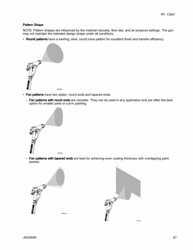
Air Caps
PatternPatternPattern ShapeShapeShape
NOTE: Pattern shapes are influenced by the material viscosity, flow rate, and air pressure settings. The gunmay not maintain the intended design shape under all conditions.
• RoundRoundRound patternspatternspatterns have a swirling, slow, round cone pattern for excellent finish and transfer efficiency.
• FanFanFan patternspatternspatterns have two styles: round ends and tapered ends.
– FanFanFan patternspatternspatterns withwithwith roundroundround endsendsends are versatile. They can be used in any application and are often the bestoption for smaller parts or cut-in painting.
– FanFanFan patternspatternspatterns withwithwith taperedtaperedtapered endsendsends are best for achieving even coating thickness with overlapping paintpasses.
3A2494N 81
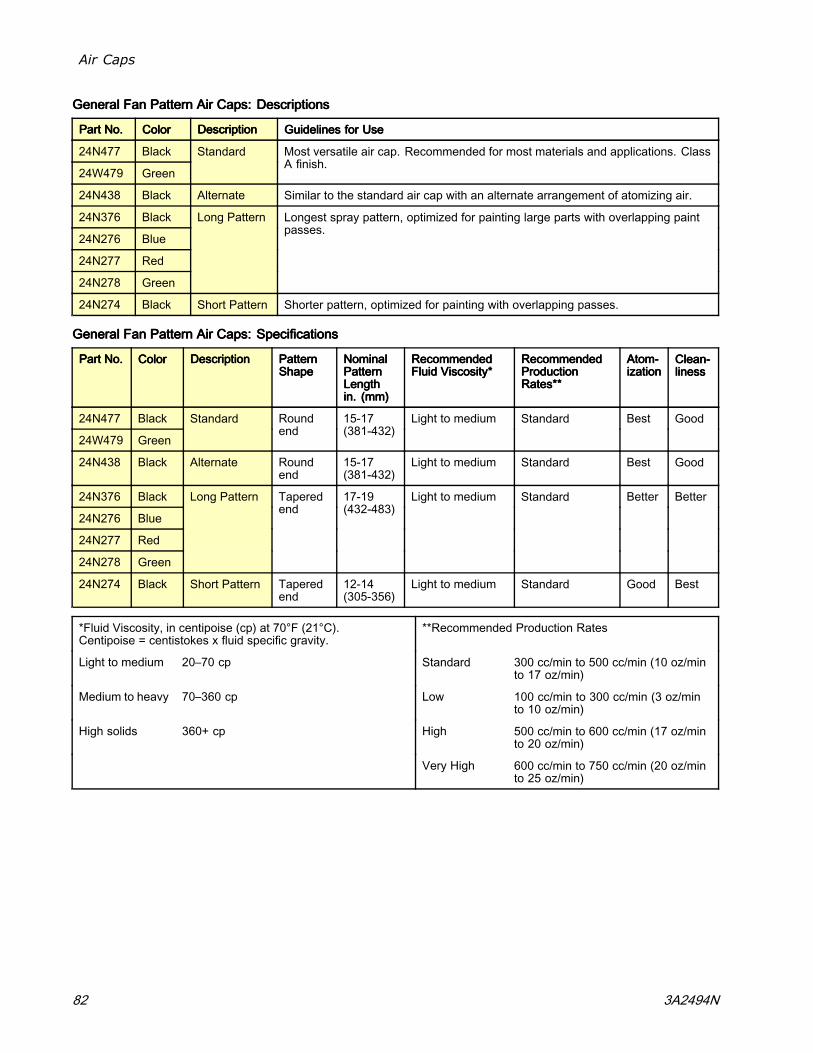
Air Caps
GeneralGeneralGeneral FanFanFan PatternPatternPattern AirAirAir Caps:Caps:Caps: DescriptionsDescriptionsDescriptions
PartPartPart No.No.No. ColorColorColor DescriptionDescriptionDescription GuidelinesGuidelinesGuidelines forforfor UseUseUse
24N477 Black
24W479 Green
Standard Most versatile air cap. Recommended for most materials and applications. ClassA finish.
24N438 Black Alternate Similar to the standard air cap with an alternate arrangement of atomizing air.
24N376 Black
24N276 Blue
24N277 Red
24N278 Green
Long Pattern Longest spray pattern, optimized for painting large parts with overlapping paintpasses.
24N274 Black Short Pattern Shorter pattern, optimized for painting with overlapping passes.
GeneralGeneralGeneral FanFanFan PatternPatternPattern AirAirAir Caps:Caps:Caps: SpecificationsSpecificationsSpecifications
PartPartPart No.No.No. ColorColorColor DescriptionDescriptionDescription PatternPatternPatternShapeShapeShape
NominalNominalNominalPatternPatternPatternLengthLengthLengthin.in.in. (mm)(mm)(mm)
RecommendedRecommendedRecommendedFluidFluidFluid Viscosity*Viscosity*Viscosity*
RecommendedRecommendedRecommendedProductionProductionProductionRates**Rates**Rates**
Atom-Atom-Atom-izationizationization
Clean-Clean-Clean-linesslinessliness
24N477 Black
24W479 Green
Standard Roundend
15-17(381-432)
Light to medium Standard Best Good
24N438 Black Alternate Roundend
15-17(381-432)
Light to medium Standard Best Good
24N376 Black
24N276 Blue
24N277 Red
24N278 Green
Long Pattern Taperedend
17-19(432-483)
Light to medium Standard Better Better
24N274 Black Short Pattern Taperedend
12-14(305-356)
Light to medium Standard Good Best
*Fluid Viscosity, in centipoise (cp) at 70°F (21°C).Centipoise = centistokes x fluid specific gravity.
**Recommended Production Rates
Light to medium 20–70 cp Standard 300 cc/min to 500 cc/min (10 oz/minto 17 oz/min)
Medium to heavy 70–360 cp Low 100 cc/min to 300 cc/min (3 oz/minto 10 oz/min)
High solids 360+ cp High 500 cc/min to 600 cc/min (17 oz/minto 20 oz/min)
Very High 600 cc/min to 750 cc/min (20 oz/minto 25 oz/min)
82 3A2494N

Air Caps
SpecialtySpecialtySpecialty FanFanFan PatternPatternPattern AirAirAir Caps:Caps:Caps: DescriptionsDescriptionsDescriptions
PartPartPart No.No.No. ColorColorColor DescriptionDescriptionDescription GuidelinesGuidelinesGuidelines forforfor UseUseUse
25E670 Black Soft Spray For painting small, lightweight parts with a slow-moving spray pattern. Optimizedfor low production rates.
24N275 Black Aerospace Optimized for aerospace coatings.
• Class A finish• Light, medium, and heavy viscosity, and high solid coatings• Very high production rates
24N279 Black Solids Optimized for medium and heavy viscosity and high solid coatings at standardproduction rates.
24N439 Black Solids HighFlow
Required for use with 2.0 mm nozzles. Optimized for medium and heavy viscosityand high solid coatings at high production rates.
25E671 Black HVLP For applications where HVLP is required.
SpecialtySpecialtySpecialty FanFanFan PatternPatternPattern AirAirAir Caps:Caps:Caps: SpecificationsSpecificationsSpecifications
PartPartPart No.No.No. ColorColorColor DescriptionDescriptionDescription PatternPatternPatternShapeShapeShape
NominalNominalNominalPatternPatternPatternLengthLengthLengthin.in.in. (mm)(mm)(mm)
RecommendedRecommendedRecommended FluidFluidFluidViscosity*Viscosity*Viscosity*
RecommendedRecommendedRecommendedProductionProductionProductionRates**Rates**Rates**
Atom-Atom-Atom-iza-iza-iza-tiontiontion
Clean-Clean-Clean-linesslinessliness
25E670 Black Soft Spray Roundend
10-12(254-305)***
Light to medium Low Better Good
24N275 Black Aerospace Taperedend
14-16(356-406)
Light, medium, andheavy viscosity, andhigh solids
Very High Good Best
24N279 Black Solids Roundend
14-16(356-406)
Medium to heavyviscosity and highsolids
Standard Better Good
24N439 Black Solids HighFlow
Taperedend
11-13(279-330)
Medium to heavyviscosity and highsolids
High Best Better
25E671 Black HVLP Roundend
11-13(279-330)
Light to medium Standard Good Good
*Fluid Viscosity, in centipoise (cp) at 70°F (21°C).Centipoise = centistokes x fluid specific gravity.
**Recommended Production Rates
Light to medium 20–70 cp Standard 300 cc/min to 500 cc/min (10 oz/minto 17 oz/min)
Medium to heavy 70–360 cp Low 100 cc/min to 300 cc/min (3 oz/minto 10 oz/min)
High solids 360+ cp High 500 cc/min to 600 cc/min (17 oz/minto 20 oz/min)
Very High 600 cc/min to 750 cc/min (20 oz/minto 25 oz/min)
***The soft spray air cap was measured with the fluid flow rate adjusted to 3.5 oz/min (100 cc/min).
3A2494N 83

Air Caps
RoundRoundRound PatternPatternPattern AirAirAir Caps:Caps:Caps: DescriptionsDescriptionsDescriptions
PartPartPart No.No.No. ColorColorColor DescriptionDescriptionDescription GuidelinesGuidelinesGuidelines forforfor UseUseUse
24N318 Black LargePattern
Conventional round pattern design for larger patterns up to 8 in (20 cm). Swirling,slow, round cone pattern for excellent finish and transfer efficiency.
25N837 Black MediumPattern
Dual inner and outer atomizing air design for improved atomization at low air flows.For medium patterns up to 6 inches (15cm). Swirling, slow, round cone pattern forexcellent finish and transfer efficiency.
25N836 Black SmallPattern
Dual inner and outer atomizing air design for improved atomization at low air flows.For small patterns up to 4 inches (10cm). Swirling, slow, round cone pattern forexcellent finish and transfer efficiency.
RoundRoundRound PatternPatternPattern AirAirAir Caps:Caps:Caps: SpecificationsSpecificationsSpecifications
PartPartPart No.No.No. ColorColorColor DescriptionDescriptionDescription PatternPatternPatternShapeShapeShape
NominalNominalNominalPatternPatternPatternDiameterDiameterDiameterin.in.in. (mm)(mm)(mm)
RecommendedRecommendedRecommended FluidFluidFluidViscosity*Viscosity*Viscosity*
RecommendedRecommendedRecommendedProductionProductionProductionRates**Rates**Rates**
Atom-Atom-Atom-iza-iza-iza-tiontiontion
Clean-Clean-Clean-linesslinessliness
24N318 Black Large Pattern Roundend
8 (203) Light to medium Low Good Good
25N837 Black MediumPattern
Roundend
6 (152) Light to medium Low Better Good
25N836 Black Small Pattern Roundend
4 (102) Light to medium Low Better Good
*Fluid Viscosity, in centipoise (cp) at 70°F (21°C).Centipoise = centistokes x fluid specific gravity.
**Recommended Production Rates
Light to medium 20–70 cp Standard 300 cc/min to 500 cc/min (10 oz/minto 17 oz/min)
Medium to heavy 70–360 cp Low 100 cc/min to 300 cc/min (3 oz/minto 10 oz/min)
High solids 360+ cp High 500 cc/min to 600 cc/min (17 oz/minto 20 oz/min)
Very High 600 cc/min to 750 cc/min (20 oz/minto 25 oz/min)
84 3A2494N

Air Caps
AirAirAir ConsumptionConsumptionConsumption ChartsChartsCharts
NOTE:NOTE:NOTE: Air consumption applies to the complete gun.
KeyKeyKey tototo AirAirAir ConsumptionConsumptionConsumption ChartsChartsCharts
TESTTESTTEST CONDITIONS:CONDITIONS:CONDITIONS: Fan valve fully open (unless otherwise noted), atomization valve fully open (unlessotherwise noted), 85kv gun.
5/16 in. x 25 ft (8 mm x 7.6 m) hose
5/16 in. x 50 ft (8 mm x 15.2 m) hose
TableTableTable 181818 ... 24N477,24N477,24N477, 24W279,24W279,24W279, 24N279,24N279,24N279, 24N376,24N376,24N376, andandand24N43824N43824N438 AirAirAir CapCapCap
600
5
10
15
20
25
62 64 66 68 70 72 74 76 78
AIRAIRAIR CON-CON-CON-SUMPTIONSUMPTIONSUMPTION
scfm
WALLWALLWALL PRESSUREPRESSUREPRESSURE
psi
TableTableTable 191919 ... 2N274,2N274,2N274, 24N275,24N275,24N275, andandand 24N43924N43924N439 AirAirAir CapCapCap
50 55 60 65 70 750
5
10
15
20
25
80
AIRAIRAIR CON-CON-CON-SUMPTIONSUMPTIONSUMPTION
scfm
WALLWALLWALL PRESSUREPRESSUREPRESSURE
psi
TableTableTable 202020 ... 25E67025E67025E670 andandand 25E67125E67125E671 AirAirAir CapCapCap
50
2
0
4
6
8
10
12
14
16
18
55 60 65 70 75 80 85
AIRAIRAIR CON-CON-CON-SUMPTIONSUMPTIONSUMPTION
scfm
WALLWALLWALL PRESSUREPRESSUREPRESSURE
psi
NOTE:NOTE:NOTE:25E670: Atomization valve opened one turn fromclose according to soft spray gun setup. SeeSoft Spray Gun Setup Procedure, page 28.
25E671: Fan valve opened two turns fromclose. Atomization valve opened one turnfrom close according to HVLP gun setup. SeeHVLP Gun Setup Procedure, page 29.
3A2494N 85

Electrode Selection Chart
ElectrodeElectrodeElectrode SelectionSelectionSelection ChartChartChart
To reduce the risk of an injury, follow the Pressure Relief Procedure, page 36, before removing or installingan electrode.
ElectrodeElectrodeElectrode PartPartPart No.No.No. ColorColorColor DescriptionDescriptionDescription GuidelinesGuidelinesGuidelines forforfor UseUseUse
24N651 Gray Standard (STD) Electrode assembly with a flexiblesnap-back wire.
The standard wire is resistant toabrasive fluid wear and also resistantto handling damage.
25N856 Gray Short Electrode assembly with a shortsnap-back wire.
The short wire has a low-profile designthat positions the wire closer to the aircap for convenience.
Use the short wire to extend wearlife of the electrode wire in extremelyabrasive materials.
24N704 Blue High wear (HW) Electrode assembly with a hard wire.
The hard wire can bend and does notsnap back if it is damaged by handling.
Use the high wear electrode to extendwear life of the wire with abrasivematerials.
25N857 Brown Hardened Electrode assembly with a hardenedcarbide wire.
The hardened wire is easier to breakwith handling than the standard orhigh wear wires.
Use the hardened electrode to extendwear life of the wire with extremelyabrasive materials.
86 3A2494N
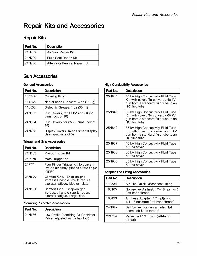
Repair Kits and Accessories
RepairRepairRepair KitsKitsKits andandand AccessoriesAccessoriesAccessories
RepairRepairRepair KitsKitsKits
PartPartPart No.No.No. DescriptionDescriptionDescription
24N789 Air Seal Repair Kit
24N790 Fluid Seal Repair Kit
24N706 Alternator Bearing Repair Kit
GunGunGun AccessoriesAccessoriesAccessories
GeneralGeneralGeneral AccessoriesAccessoriesAccessories
PartPartPart No.No.No. DescriptionDescriptionDescription
105749 Cleaning Brush
111265 Non-silicone Lubricant, 4 oz (113 g)
116553 Dielectric Grease, 1 oz (30 ml)
24N603 Gun Covers, for 40 kV and 60 kVguns (box of 10)
24N604 Gun Covers, for 85 kV guns (box of10)
24N758 Display Covers. Keeps Smart displayclean (package of 5).
TriggerTriggerTrigger andandand GripGripGrip AccessoriesAccessoriesAccessories
PartPartPart No.No.No. DescriptionDescriptionDescription
24N633 Plastic Trigger Kit
24P170 Metal Trigger Kit
24P171 Four Finger Trigger Kit, to convertPro Xp air spray guns to a four fingertrigger
24N520 Comfort Grip. Snap-on gripincreases handle size to reduceoperator fatigue. Medium size.
24N521 Comfort Grip. Snap-on gripincreases handle size to reduceoperator fatigue. Large size.
AtomizingAtomizingAtomizing AirAirAir ValveValveValve AccessoriesAccessoriesAccessories
PartPartPart No.No.No. DescriptionDescriptionDescription
24N636 Low Profile Atomizing Air RestrictorValve (adjusted with a hex tool)
HighHighHigh ConductivityConductivityConductivity AccessoriesAccessoriesAccessories
PartPartPart No.No.No. DescriptionDescriptionDescription
25N844 40 kV High Conductivity Fluid TubeKit, with cover. To convert a 40 kVgun from a standard fluid tube to anHC fluid tube.
25N843 60 kV High Conductivity Fluid TubeKit, with cover. To convert a 60 kVgun from a standard fluid tube to anHC fluid tube.
25N842 85 kV High Conductivity Fluid TubeKit, with cover. To convert an 85 kVgun from a standard fluid tube to anHC fluid tube.
25N937 40 kV High Conductivity Fluid TubeKit, no cover
25N936 60 kV High Conductivity Fluid TubeKit, no cover
25N935 85 kV High Conductivity Fluid TubeKit, no cover
AdapterAdapterAdapter andandand FittingFittingFitting AccessoriesAccessoriesAccessories
PartPartPart No.No.No. DescriptionDescriptionDescription
112534 Air Line Quick Disconnect Fitting
185105 Non-swivel Air Inlet; 1/4–18 npsm(m)(left-hand thread)
185493 Air Hose Adapter; 1/4 npt(m) x1/4–18 npsm(m) (left-hand thread)
24N642 Ball Swivel, for gun air inlet; 1/4npsm (left-hand thread)
224754 Valve, ball 1/4 npsm (left-handthread)
3A2494N 87

Repair Kits and Accessories
ESESES On/OffOn/OffOn/Off andandand FluidFluidFluid AdjustmentAdjustmentAdjustment ValveValveValve AccessoriesAccessoriesAccessories
PartPartPart No.No.No. DescriptionDescriptionDescription
26A160 ES On/Off Valve Restrictor for highatomizing air applications. Usethis accessory if the turbine lightindicator is red and you want tomaintain a higher application airpressure. Install the kit, then adjustthe pressure as needed to ensurethe indicator remains green.
24P634 ES Always ON and fluid adjustmentvalve. When this valve is installed,the electrostatics are on anytime airpressure is supplied to the gun. Fluidadjustment is possible. Must be usedwith 224754 ball valve installed at thegun air inlet. See manual 3A6840.
24N630 ES On-Off and Fluid AdjustmentValve
24N632 ES On-Off and Fixed Fluid Valve.Use to extend electrode and nozzlelife in applications with abrasive,metallic, and extremely abrasivematerials.
FanFanFan AirAirAir AdjustmentAdjustmentAdjustment ValveValveValve AccessoriesAccessoriesAccessories
PartPartPart No.No.No. DescriptionDescriptionDescription
24N634 Standard fan air adjustment valve
24N732 Fan air adjustment valve for largepattern round spray
24P172 Quick adjust fan valve for quickchange of fan size
25N919 Quick adjust fan valve with springreturn
RoundRoundRound SpraySpraySpray AccessoriesAccessoriesAccessories
PartPartPart No.No.No. DescriptionDescriptionDescription
24N318 Round Spray Kit, large pattern, toconvert a standard air spray gun toa round spray air cap. See manual3A2498.
25N837 Round Spray Kit, medium pattern, toconvert a standard air spray gun toa round spray air cap. See manual3A6829.
25N836 Round Spray Kit, small pattern, toconvert a standard air spray gun toa round spray air cap. See manual3A6829.
OperatorOperatorOperator AccessoriesAccessoriesAccessories
PartPartPart No.No.No. DescriptionDescriptionDescription
117823 Conductive Gloves, box of 12 (small)
117824 Conductive Gloves, box of 12(medium)
117825 Conductive Gloves, box of 12 (large)
SystemSystemSystem AccessoriesAccessoriesAccessories
PartPartPart No.No.No. DescriptionDescriptionDescription
222011 Ground Wire and Clamp
24N528 Gun Flush Box Adapter for 60 kVand 85 kV guns. To convert existinggun flush boxes to hold Pro Xp guns.See manual 309227.
24N529 Gun Flush Box Adapter for 40 kVguns. To convert existing gun flushboxes to hold Pro Xp guns. Seemanual 309227.
24P312 Gun Washer Kit. To convert existinggun washers to clean Pro Xp guns.See manual 308393.
SignsSignsSigns
PartPartPart No.No.No. DescriptionDescriptionDescription
16P802 English Warning Sign, available atno charge from Graco
16P798 English Daily Care Sign
16P799 English Setup Sign
88 3A2494N

Repair Kits and Accessories
TestTestTest EquipmentEquipmentEquipment
PartPartPart No.No.No. DescriptionDescriptionDescription
241079 Megohmmeter. 500 V output,0.01–2000 megohms. Use forground continuity and gun resistancetests.NotNotNot forforfor useuseuse ininin hazardoushazardoushazardouslocations.locations.locations.
722886 Paint Resistance Meter. Use for fluidresistivity test. See manual 307263.NotNotNot forforfor useuseuse ininin hazardoushazardoushazardous locations.locations.locations.
722860 Paint Probe. Use for fluid resistivitytest. See manual 307263. NotNotNot forforforuseuseuse ininin hazardoushazardoushazardous locations.locations.locations.
245277 Test Fixture, High Voltage Probe,and kV Meter. Use to test theelectrostatic voltage of the gun, andthe condition of the alternator andpower supply when being serviced.See manual 309455. Also requires24R038 Conversion Kit.
PartPartPart No.No.No. DescriptionDescriptionDescription
24R038 Voltage Tester Conversion Kit.Converts the 245277 Test Fixture foruse with the Pro Xp Gun alternator.See manual 406999.
25E919 HVLP Air Cap Verification Kit. Useto verify air pressures in air capsin HVLP applications. For usewith 25E671 air cap. See manual3A6833.
3A2494N 89

Repair Kits and Accessories
HosesHosesHoses
GroundedGroundedGrounded AirAirAir HosesHosesHoses
100 psi (0.7 MPa, 7 bar) Maximum Working Pressure0.315 in. (8 mm) ID; 1/4 npsm(f) x 1/4 npsm(f) left-hand thread
PartPartPart No.No.No. DescriptionDescriptionDescription
AirFlexAirFlexAirFlex FlexibleFlexibleFlexible GroundedGroundedGrounded AirAirAir HoseHoseHose (Gray)(Gray)(Gray)
244963 6 ft (1.8 m)
244964 15 ft (4.6 m)
244965 25 ft (7.6 m)
24J138 31 ft (9.4 m)
24N736 25 ft (7.6 m), with 112534 QuickDisconnect
244966 36 ft (11 m)
24N737 36 ft (11 m), with 112534 QuickDisconnect
244967 50 ft (15 m)
24N738 50 ft (15 m), with 112534 QuickDisconnect
244968 75 ft (23 m)
244969 100 ft (30.5 m)
PartPartPart No.No.No. DescriptionDescriptionDescription
StandardStandardStandard GroundedGroundedGrounded AirAirAir HoseHoseHose (Gray)(Gray)(Gray)
223068 6 ft (1.8 m)
223069 15 ft (4.6 m)
223070 25 ft (7.6 m)
223071 36 ft (11 m)
223072 50 ft (15 m)
223073 75 ft (23 m)
223074 100 ft (30.5 m)
0.3750.3750.375 in.in.in. (10(10(10 mm)mm)mm) ID;ID;ID; 3/83/83/8 npsm(f)npsm(f)npsm(f) xxx 1/41/41/4 npsm(f)npsm(f)npsm(f)leftleftleft---handhandhand threadthreadthread
24A225 50 ft (15 m)
24A226 75 ft (23 m)
PartPartPart No.No.No. DescriptionDescriptionDescription
GroundedGroundedGrounded AirAirAir HoseHoseHose withwithwith stainlessstainlessstainless steelsteelsteel braidbraidbraidgroundgroundground pathpathpath (Red)(Red)(Red)
235068 6 ft (1.8 m)
235069 15 ft (4.6 m)
235070 25 ft (7.6 m)
235071 36 ft (11 m)
235072 50 ft (15 m)
235073 75 ft (23 m)
235074 100 ft (30.5 m)
AirAirAir WhipWhipWhip HosesHosesHoses
100 psi (0.7 MPa, 7 bar) Maximum Working Pressure0.188 in. (5 mm) ID; 1/4 npsm(m) x 1/4 npsm(f)left-hand thread
PartPartPart No.No.No. DescriptionDescriptionDescription
AirAirAir WhipWhipWhip HoseHoseHose withwithwith stainlessstainlessstainless steelsteelsteel braidbraidbraid groundgroundgroundpathpathpath (Red)(Red)(Red)
236130 3 ft (0.9 m)
236131 6 ft (1.8 m)
FluidFluidFluid HosesHosesHoses
225 psi (1.4 MPa, 14 bar) Maximum WorkingPressure1/4 in. (6 mm) ID; 3/8 npsm(fbe); nylon
PartPartPart No.No.No. DescriptionDescriptionDescription
215637 25 ft (7.6 m)
215638 50 ft (15 m)
HighHighHigh ConductivityConductivityConductivity FluidFluidFluid HoseHoseHose
For low resistivity, high viscosity materials. ForForFor 606060kVkVkV gunsgunsguns only.only.only.
100 psi (0.7 MPa, 7 bar) Maximum Working Pressure1/4 in. (6 mm) ID; 3/8 npsm(f) x 5/8–20(m); PTFE
PartPartPart No.No.No. DescriptionDescriptionDescription
24N994 26.8 ft (8.2 m)
90 3A2494N

Dimensions
DimensionsDimensionsDimensions
DimensionsDimensionsDimensionsKVKVKV DisplayDisplayDisplay FluidFluidFluidTubeTubeTube
A,A,A, in.in.in. (mm)(mm)(mm) B,B,B, in.in.in. (mm)(mm)(mm) C,C,C, in.in.in. (mm)(mm)(mm)
Weight,Weight,Weight, ozozoz (g)(g)(g)
40 Standard Standard 8.7 (221) 9.2 (234) 2.4 (61) 19.8 (562)
40 Standard HC 8.7 (221) 9.2 (234) 2.4 (61) 20.5 (620)
40 Smart Standard 8.7 (221) 10 (254) 2.4 (61) 22.3 (632)
40 Smart HC 8.7 (221) 10 (254) 2.4 (61) 24.3 (690)
60 Standard Standard 9.5 (241) 9.2 (234) 2.4 (61) 21.1 (600)
60 Standard HC 9.5 (241) 9.2 (234) 2.4 (61) 23.3 (660)
60 Smart Standard 9.5 (241) 10 (254) 2.4 (61) 23.7 (673)
60 Smart HC 9.5 (241) 10 (254) 2.4 (61) 25.9 (733)
85 Standard Standard 10.5 (267) 9.2 (234) 2.4 (61) 23.8 (676)
85 Standard HC 10.5 (267) 9.2 (234) 2.4 (61) 26.2 (743)
85 Smart Standard 10.5 (267) 10 (254) 2.4 (61) 26.3 (746)
85 Smart HC 10.5 (267) 10 (254) 2.4 (61) 28.7 (813)
See Models, page 3 for gun part numbers.
3A2494N 91

Notes
NotesNotesNotes
92 3A2494N

Technical Specifications
TechnicalTechnicalTechnical SpecificationsSpecificationsSpecificationsElectrostaticElectrostaticElectrostatic AirAirAir SpraySpraySpray GunsGunsGuns
U.S.U.S.U.S. MetricMetricMetricMaximum Working Fluid Pressure 100 psi 0.7 MPa, 7.0 barMaximum Working Air Pressure 100 psi 0.7 MPa, 7.0 barMinimum Air Pressure at Gun Inlet 45 psi 0.32 MPa, 3.2 barAir ConsumptionRequired turbine air flow 6 scfm 170 l/minRange of total air flow undernormal spraying conditions
15–20 scfm 425–565 l/min
Maximum Fluid OperatingTemperature
120°F 48°C
Ambient Temperature 41°–122°F 5°–50°CPaint Resistivity Range 3 megohm/cm to infinity. For a table of electrostatic results at different
resistance levels, see Check Fluid Resistivity, page 35.Air Inlet Fitting 1/4 npsm(m) left-hand threadFluid Inlet Fitting 3/8 npsm(m)Output Voltage Pro Xp40 Models: 40 kV
Pro Xp60 Models: 60 kV
Pro Xp85 Models: 85 kVMaximum Current Draw 125 microamperesSound Power (measured per ISOStandard 9216)
at 40 psi: 90.4 dB(A)
at 100 psi: 105.4 dB(A)
at 0.28 MPa, 2.8 bar: 90.4 dB(A)
at 0.7 MPa, 7.0 bar: 105.4 dB(A)Sound Pressure (measured 1 mfrom gun)
at 40 psi: 87.0 dB(A)
at 100 psi: 99.0 dB(A)
at 0.28 MPa, 2.8 bar: 87.0 dB(A)
at 0.7 MPa, 7.0 bar: 99.0 dB(A)Wetted Parts PEEK, UHMWPE, FEP, PTFE, acetal, nylon, polyeth-
ylene, stainless steel
3A2494N 93

GracoGracoGraco ProProPro XpXpXp WarrantyWarrantyWarranty
Graco warrants all equipment referenced in this document which is manufactured by Graco and bearing its nameto be free from defects in material and workmanship on the date of sale to the original purchaser for use. With theexception of any special, extended, or limited warranty published by Graco, Graco will, for a period of twelve monthsfrom the date of sale, repair or replace any part of the equipment determined by Graco to be defective. However, anydeficiency in the barrel, handle, trigger, hook, internal power supply, and alternator (excluding turbine bearings) will berepaired or replaced for thirty-six months from the date of sale. This warranty applies only when the equipment isinstalled, operated and maintained in accordance with Graco’s written recommendations.
This warranty does not cover, and Graco shall not be liable for general wear and tear, or any malfunction, damageor wear caused by faulty installation, misapplication, abrasion, corrosion, inadequate or improper maintenance,negligence, accident, tampering, or substitution of non-Graco component parts. Nor shall Graco be liable formalfunction, damage or wear caused by the incompatibility of Graco equipment with structures, accessories,equipment or materials not supplied by Graco, or the improper design, manufacture, installation, operation ormaintenance of structures, accessories, equipment or materials not supplied by Graco.
This warranty is conditioned upon the prepaid return of the equipment claimed to be defective to an authorizedGraco distributor for verification of the claimed defect. If the claimed defect is verified, Graco will repair or replacefree of charge any defective parts. The equipment will be returned to the original purchaser transportation prepaid.If inspection of the equipment does not disclose any defect in material or workmanship, repairs will be made at areasonable charge, which charges may include the costs of parts, labor, and transportation.
THISTHISTHIS WARRANTYWARRANTYWARRANTY ISISIS EXCLUSIVE,EXCLUSIVE,EXCLUSIVE, ANDANDAND ISISIS INININ LIEULIEULIEU OFOFOF ANYANYANY OTHEROTHEROTHER WARRANTIES,WARRANTIES,WARRANTIES, EXPRESSEXPRESSEXPRESS OROROR IMPLIED,IMPLIED,IMPLIED,INCLUDINGINCLUDINGINCLUDING BUTBUTBUT NOTNOTNOT LIMITEDLIMITEDLIMITED TOTOTO WARRANTYWARRANTYWARRANTY OFOFOF MERCHANTABILITYMERCHANTABILITYMERCHANTABILITY OROROR WARRANTYWARRANTYWARRANTY OFOFOF FITNESSFITNESSFITNESS FORFORFOR AAAPARTICULARPARTICULARPARTICULAR PURPOSE.PURPOSE.PURPOSE.
Graco’s sole obligation and buyer’s sole remedy for any breach of warranty shall be as set forth above. The buyeragrees that no other remedy (including, but not limited to, incidental or consequential damages for lost profits, lostsales, injury to person or property, or any other incidental or consequential loss) shall be available. Any action forbreach of warranty must be brought within two (2) years of the date of sale.
GRACOGRACOGRACO MAKESMAKESMAKES NONONO WARRANTY,WARRANTY,WARRANTY, ANDANDAND DISCLAIMSDISCLAIMSDISCLAIMS ALLALLALL IMPLIEDIMPLIEDIMPLIED WARRANTIESWARRANTIESWARRANTIES OFOFOF MERCHANTABILITYMERCHANTABILITYMERCHANTABILITY ANDANDANDFITNESSFITNESSFITNESS FORFORFOR AAA PARTICULARPARTICULARPARTICULAR PURPOSE,PURPOSE,PURPOSE, INININ CONNECTIONCONNECTIONCONNECTION WITHWITHWITH ACCESSORIES,ACCESSORIES,ACCESSORIES, EQUIPMENT,EQUIPMENT,EQUIPMENT, MATERIALSMATERIALSMATERIALSOROROR COMPONENTSCOMPONENTSCOMPONENTS SOLDSOLDSOLD BUTBUTBUT NOTNOTNOT MANUFACTUREDMANUFACTUREDMANUFACTURED BYBYBY GRACO.GRACO.GRACO. These items sold, but not manufactured byGraco (such as electric motors, switches, hose, etc.), are subject to the warranty, if any, of their manufacturer. Gracowill provide purchaser with reasonable assistance in making any claim for breach of these warranties.
In no event will Graco be liable for indirect, incidental, special or consequential damages resulting from Gracosupplying equipment hereunder, or the furnishing, performance, or use of any products or other goods sold hereto,whether due to a breach of contract, breach of warranty, the negligence of Graco, or otherwise.
FOR GRACO CANADA CUSTOMERSThe Parties acknowledge that they have required that the present document, as well as all documents, notices andlegal proceedings entered into, given or instituted pursuant hereto or relating directly or indirectly hereto, be drawnup in English. Les parties reconnaissent avoir convenu que la rédaction du présente document sera en Anglais,ainsi que tous documents, avis et procédures judiciaires exécutés, donnés ou intentés, à la suite de ou en rapport,directement ou indirectement, avec les procédures concernées.
GracoGracoGraco InformationInformationInformationForForFor thethethe latestlatestlatest informationinformationinformation aboutaboutabout GracoGracoGraco products,products,products, visitvisitvisit www.graco.com.ForForFor patentpatentpatent information,information,information, seeseesee www.graco.com/patents.
ToToTo placeplaceplace ananan order,order,order, contact your Graco Distributor or call to identify the nearest distributor.
Phone:Phone:Phone: 612-623-6921 ororor TollTollToll Free:Free:Free: 1-800-328-0211 Fax:Fax:Fax: 612-378-3505
All written and visual data contained in this document reflects the latest product information available at the time of publication.
Graco reserves the right to make changes at any time without notice.
Original Instructions. This manual contains English, MM 3A2494
GracoGracoGraco Headquarters:Headquarters:Headquarters: Minneapolis
InternationalInternationalInternational Offices:Offices:Offices: Belgium, China, Japan, Korea
GRACOGRACOGRACO INC.INC.INC. ANDANDAND SUBSIDIARIESSUBSIDIARIESSUBSIDIARIES ••• P.O.P.O.P.O. BOXBOXBOX 144114411441 ••• MINNEAPOLIS,MINNEAPOLIS,MINNEAPOLIS, MNMNMN 55440-144155440-144155440-1441 ••• USAUSAUSA
CopyrightCopyrightCopyright 2012,2012,2012, GracoGracoGraco Inc.Inc.Inc. AllAllAll GracoGracoGraco manufacturingmanufacturingmanufacturing locationslocationslocations areareare registeredregisteredregistered tototo ISOISOISO 9001.9001.9001.
www.graco.com
Revision N, 2019–03