3A2494L, Pro Xp™ Electrostatic Air Spray Gun, Instructions ... · Warnings Warnings...
78
Instructions - Parts Pro Xp™ Electrostatic Air Spray Gun 3A2494L EN For use in Class I, Div. I Hazardous Locations using Group D materials. For use in Group II, Zone 1 Explosive Atmosphere Locations using Group IIA materials. For professional use only. Important Safety Instructions This equipment could present hazards if not operated according to the information in this manual. Read all warnings and instructions in this manual. Save these instructions. 100 psi (0.7 MPa, 7.0 bar) Maximum Fluid Working Pressure 100 psi (0.7 MPa, 7.0 bar) Maximum Air Working Pressure See page 3 for model part numbers and approval information. PROVEN QUALITY. LEADING TECHNOLOGY.
Transcript of 3A2494L, Pro Xp™ Electrostatic Air Spray Gun, Instructions ... · Warnings Warnings...
Instructions - Parts
Pro Xp™ Electrostatic
Air Spray Gun 3A2494LEN
For use in Class I, Div. I Hazardous Locations using Group D materials.For use in Group II, Zone 1 Explosive Atmosphere Locations using Group IIA materials. For professionaluse only.
Important Safety InstructionsThis equipment could present hazards if not operated according tothe information in this manual. Read all warnings and instructions inthis manual. Save these instructions.
100 psi (0.7 MPa, 7.0 bar) MaximumFluid Working Pressure100 psi (0.7 MPa, 7.0 bar) Maximum AirWorking Pressure
See page 3 for model part numbers andapproval information.
PROVEN QUALITY. LEADING TECHNOLOGY.
ContentsModels............................................................... 3Warnings ........................................................... 4Gun Overview .................................................... 7
How the Electrostatic Spray GunWorks ............................................ 7
Controls, Indicators, and Components ........... 8Smart Guns ................................................. 9
Installation.......................................................... 15Warning Sign............................................... 15Ventilate the Spray Booth ............................. 15Air Supply Line ............................................ 16Fluid Supply Line ......................................... 16
Gun Setup.......................................................... 18Gun Setup Checklist .................................... 18Grounding ................................................... 21Check Gun Electrical Grounding ................... 25Check Fluid Resistivity ................................. 26Check Fluid Viscosity ................................... 26Flush Before Using Equipment...................... 26Guidelines for Abrasive Materials .................. 26
Operation ........................................................... 27Pressure Relief Procedure............................ 27Startup ........................................................ 27Shutdown .................................................... 27
Maintenance ...................................................... 28Flushing ...................................................... 28Clean the Gun Daily ..................................... 29Daily System Care ....................................... 30
Electrical Tests ................................................... 31Test Gun Resistance.................................... 31Test Power Supply Resistance ..................... 32Test Electrode Resistance ............................ 32
Troubleshooting.................................................. 33Spray Pattern Troubleshooting...................... 33Gun Operation Troubleshooting .................... 34Electrical Troubleshooting ............................ 35
Repair................................................................ 37Prepare the Gun for Service ......................... 37Air Cap and Nozzle Replacement.................. 38Electrode Replacement ................................ 39Fluid Packing Rod Removal.......................... 40Packing Rod Repair ..................................... 40Barrel Removal ............................................ 42
Barrel Installation ......................................... 42Power Supply Removal and
Replacement .................................. 43Alternator Removal and Replacement ........... 44Fluid Tube Removal and Replacement ........... 46Fan Air Adjustment Valve Repair .................. 47Atomizing Air Restrictor Valve Repair ............ 48ES On-Off and Fluid Adjustment Valve
Repair............................................ 49Air Valve Repair........................................... 50Smart Module Replacement.......................... 51Air Swivel and Exhaust Valve
Replacement .................................. 52Parts.................................................................. 53
Standard Air Spray Gun Assembly ................ 53Round Spray Assembly ................................ 55Standard High Conductivity Air Spray Gun
Assembly ....................................... 56Smart High Conductivity Air Spray Gun
Assembly ....................................... 58Smart Air Spray Gun Assembly..................... 60Packing Rod Assembly................................. 62Alternator Assembly ..................................... 63ES On-Off and Fluid Adjustment Valve ........... 64Fan Air Adjustment Valve Assembly .............. 65Atomizing Air Restrictor Valve
Assembly ....................................... 65Smart Module Assembly............................... 66High Conductivity Fluid Tube
Assembly ....................................... 67Air Caps and Fluid Nozzles ................................. 68
Fluid Nozzle Selection Chart......................... 68Fluid Nozzle Performance Charts.................. 68Air Cap Selection Chart ................................ 70Air Consumption Charts ............................... 71
Repair Kits, Related Manuals, andAccessories .......................................... 73
Gun Accessories.......................................... 73Operator Accessories................................... 74System Accessories..................................... 74Test Equipment ........................................... 74Hoses ......................................................... 75
Dimensions ........................................................ 76Technical Data ................................................... 77
2 3A2494L
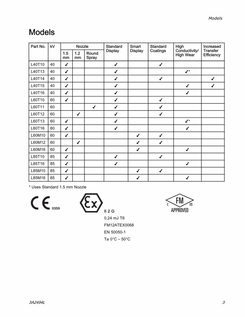
Models
ModelsNozzlePart No. kV
1.5mm
1.2mm
RoundSpray
StandardDisplay
SmartDisplay
StandardCoatings
HighConductivity/High Wear
IncreasedTransferEfficiency
L40T10 40 ✔ ✔ ✔L40T13 40 ✔ ✔ ✔*L40T14 40 ✔ ✔ ✔ ✔L40T15 40 ✔ ✔ ✔ ✔L40T16 40 ✔ ✔ ✔L60T10 60 ✔ ✔ ✔L60T11 60 ✔ ✔ ✔L60T12 60 ✔ ✔ ✔L60T13 60 ✔ ✔ ✔*L60T16 60 ✔ ✔ ✔L60M10 60 ✔ ✔ ✔L60M12 60 ✔ ✔ ✔L60M16 60 ✔ ✔ ✔L85T10 85 ✔ ✔ ✔L85T16 85 ✔ ✔ ✔L85M10 85 ✔ ✔ ✔L85M16 85 ✔ ✔ ✔
* Uses Standard 1.5 mm Nozzle
II 2 G0.24 mJ T6
FM12ATEX0068
EN 50050-1
Ta 0°C – 50°C
3A2494L 3
Warnings
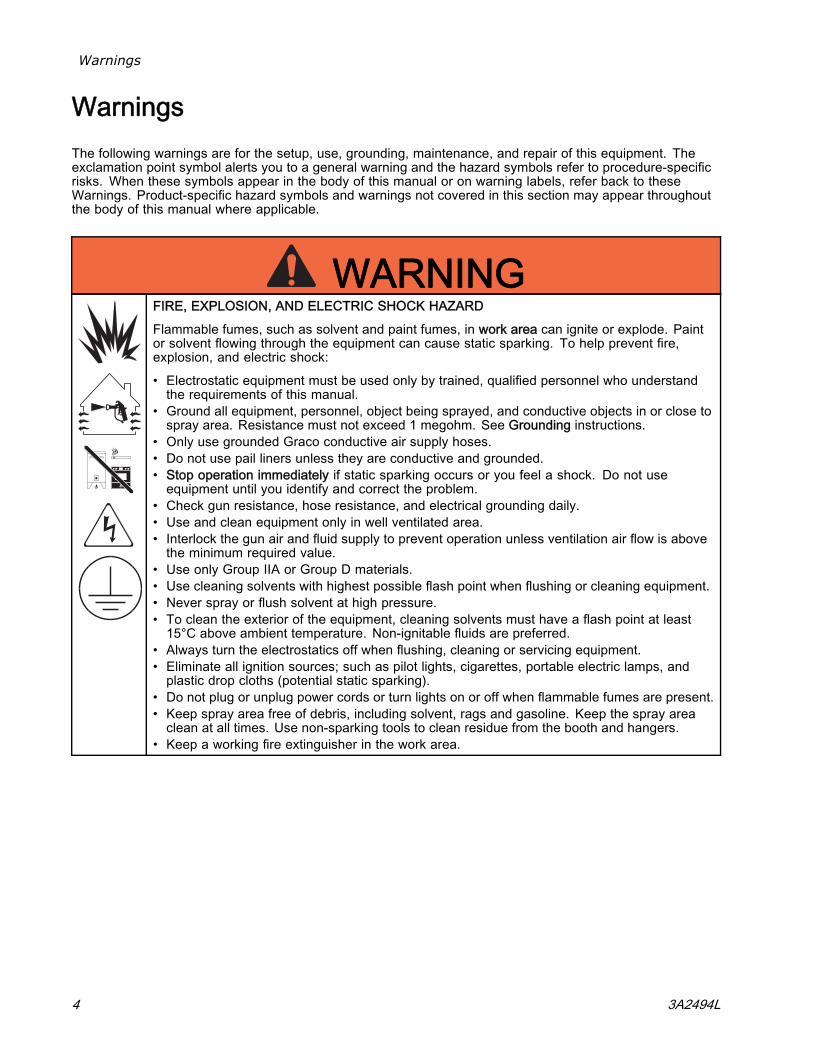
WarningsThe following warnings are for the setup, use, grounding, maintenance, and repair of this equipment. Theexclamation point symbol alerts you to a general warning and the hazard symbols refer to procedure-specificrisks. When these symbols appear in the body of this manual or on warning labels, refer back to theseWarnings. Product-specific hazard symbols and warnings not covered in this section may appear throughoutthe body of this manual where applicable.
WARNINGFIRE, EXPLOSION, AND ELECTRIC SHOCK HAZARD
Flammable fumes, such as solvent and paint fumes, in work area can ignite or explode. Paintor solvent flowing through the equipment can cause static sparking. To help prevent fire,explosion, and electric shock:
• Electrostatic equipment must be used only by trained, qualified personnel who understandthe requirements of this manual.
• Ground all equipment, personnel, object being sprayed, and conductive objects in or close tospray area. Resistance must not exceed 1 megohm. See Grounding instructions.
• Only use grounded Graco conductive air supply hoses.• Do not use pail liners unless they are conductive and grounded.• Stop operation immediately if static sparking occurs or you feel a shock. Do not useequipment until you identify and correct the problem.
• Check gun resistance, hose resistance, and electrical grounding daily.• Use and clean equipment only in well ventilated area.• Interlock the gun air and fluid supply to prevent operation unless ventilation air flow is abovethe minimum required value.
• Use only Group IIA or Group D materials.• Use cleaning solvents with highest possible flash point when flushing or cleaning equipment.• Never spray or flush solvent at high pressure.• To clean the exterior of the equipment, cleaning solvents must have a flash point at least15°C above ambient temperature. Non-ignitable fluids are preferred.
• Always turn the electrostatics off when flushing, cleaning or servicing equipment.• Eliminate all ignition sources; such as pilot lights, cigarettes, portable electric lamps, andplastic drop cloths (potential static sparking).
• Do not plug or unplug power cords or turn lights on or off when flammable fumes are present.• Keep spray area free of debris, including solvent, rags and gasoline. Keep the spray areaclean at all times. Use non-sparking tools to clean residue from the booth and hangers.
• Keep a working fire extinguisher in the work area.
4 3A2494L
Warnings
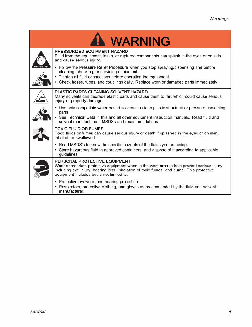
WARNINGPRESSURIZED EQUIPMENT HAZARDFluid from the equipment, leaks, or ruptured components can splash in the eyes or on skinand cause serious injury.
• Follow the Pressure Relief Procedure when you stop spraying/dispensing and beforecleaning, checking, or servicing equipment.
• Tighten all fluid connections before operating the equipment.• Check hoses, tubes, and couplings daily. Replace worn or damaged parts immediately.
PLASTIC PARTS CLEANING SOLVENT HAZARDMany solvents can degrade plastic parts and cause them to fail, which could cause seriousinjury or property damage.
• Use only compatible water-based solvents to clean plastic structural or pressure-containingparts.
• See Technical Data in this and all other equipment instruction manuals. Read fluid andsolvent manufacturer’s MSDSs and recommendations.
TOXIC FLUID OR FUMESToxic fluids or fumes can cause serious injury or death if splashed in the eyes or on skin,inhaled, or swallowed.
• Read MSDS’s to know the specific hazards of the fluids you are using.• Store hazardous fluid in approved containers, and dispose of it according to applicableguidelines.
PERSONAL PROTECTIVE EQUIPMENTWear appropriate protective equipment when in the work area to help prevent serious injury,including eye injury, hearing loss, inhalation of toxic fumes, and burns. This protectiveequipment includes but is not limited to:
• Protective eyewear, and hearing protection.• Respirators, protective clothing, and gloves as recommended by the fluid and solventmanufacturer.
3A2494L 5
Warnings
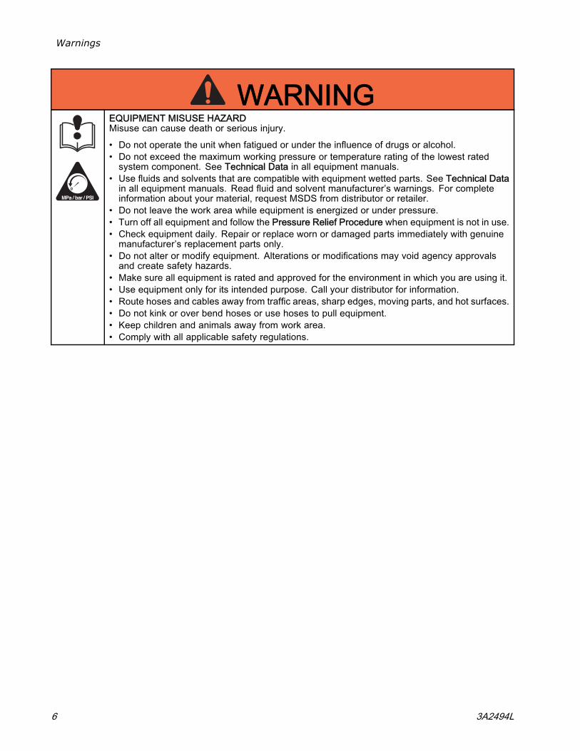
WARNINGEQUIPMENT MISUSE HAZARDMisuse can cause death or serious injury.
• Do not operate the unit when fatigued or under the influence of drugs or alcohol.• Do not exceed the maximum working pressure or temperature rating of the lowest ratedsystem component. See Technical Data in all equipment manuals.
• Use fluids and solvents that are compatible with equipment wetted parts. See Technical Datain all equipment manuals. Read fluid and solvent manufacturer’s warnings. For completeinformation about your material, request MSDS from distributor or retailer.
• Do not leave the work area while equipment is energized or under pressure.• Turn off all equipment and follow the Pressure Relief Procedure when equipment is not in use.• Check equipment daily. Repair or replace worn or damaged parts immediately with genuinemanufacturer’s replacement parts only.
• Do not alter or modify equipment. Alterations or modifications may void agency approvalsand create safety hazards.
• Make sure all equipment is rated and approved for the environment in which you are using it.• Use equipment only for its intended purpose. Call your distributor for information.• Route hoses and cables away from traffic areas, sharp edges, moving parts, and hot surfaces.• Do not kink or over bend hoses or use hoses to pull equipment.• Keep children and animals away from work area.• Comply with all applicable safety regulations.
6 3A2494L
Gun Overview
Gun Overview
How the Electrostatic Spray Gun Works
The air hose supplies air to the spray gun. Part ofthe air operates the alternator turbine and the restof the air atomizes the fluid being sprayed. Thealternator generates power, which is converted bythe power cartridge to supply high voltage to thegun’s electrode.
The pump supplies fluid to the fluid hose and gun,where the fluid is electrostatically charged as itpasses the electrode. The charged fluid is attractedto the grounded workpiece, wrapping around andevenly coating all surfaces.
3A2494L 7
Gun Overview
Controls, Indicators, and Components
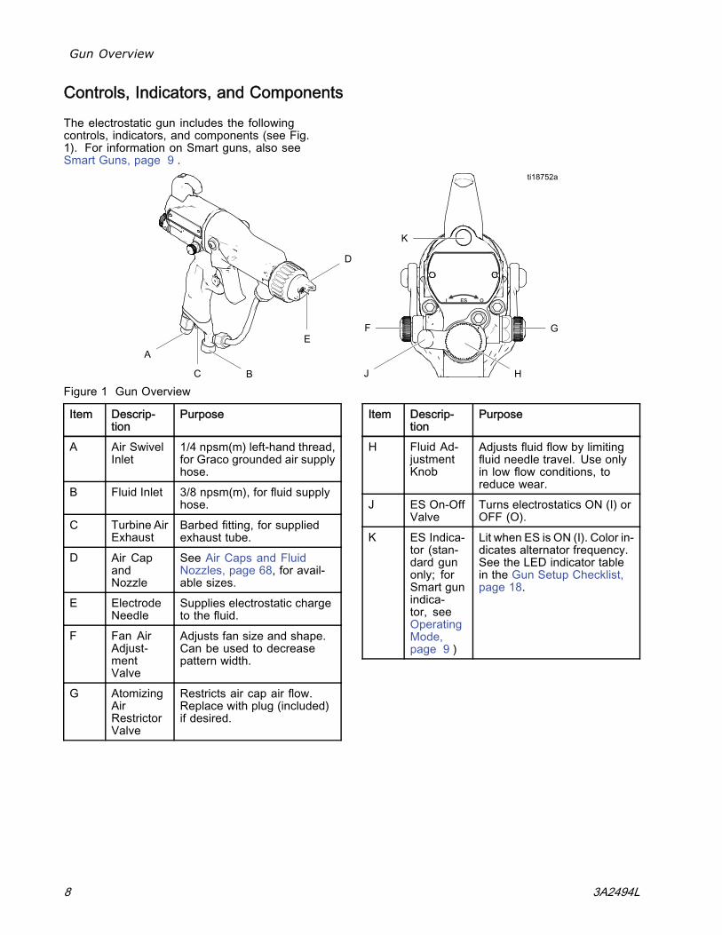
The electrostatic gun includes the followingcontrols, indicators, and components (see Fig.1). For information on Smart guns, also seeSmart Guns, page 9 .
Figure 1 Gun Overview
Item Descrip-tion
Purpose
A Air SwivelInlet
1/4 npsm(m) left-hand thread,for Graco grounded air supplyhose.
B Fluid Inlet 3/8 npsm(m), for fluid supplyhose.
C Turbine AirExhaust
Barbed fitting, for suppliedexhaust tube.
D Air CapandNozzle
See Air Caps and FluidNozzles, page 68, for avail-able sizes.
E ElectrodeNeedle
Supplies electrostatic chargeto the fluid.
F Fan AirAdjust-mentValve
Adjusts fan size and shape.Can be used to decreasepattern width.
G AtomizingAirRestrictorValve
Restricts air cap air flow.Replace with plug (included)if desired.
Item Descrip-tion
Purpose
H Fluid Ad-justmentKnob
Adjusts fluid flow by limitingfluid needle travel. Use onlyin low flow conditions, toreduce wear.
J ES On-OffValve
Turns electrostatics ON (I) orOFF (O).
K ES Indica-tor (stan-dard gunonly; forSmart gunindica-tor, seeOperatingMode,page 9 )
Lit when ES is ON (I). Color in-dicates alternator frequency.See the LED indicator tablein the Gun Setup Checklist,page 18.
8 3A2494L
Gun Overview
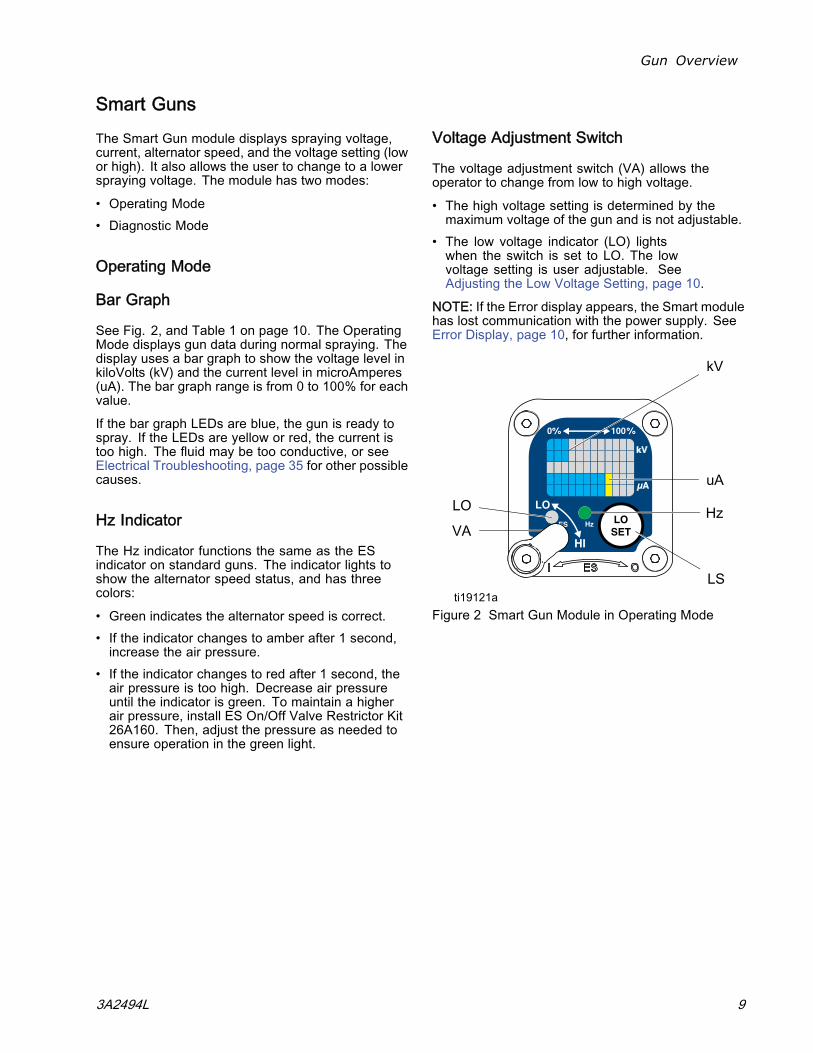
Smart GunsThe Smart Gun module displays spraying voltage,current, alternator speed, and the voltage setting (lowor high). It also allows the user to change to a lowerspraying voltage. The module has two modes:
• Operating Mode• Diagnostic Mode
Operating Mode
Bar Graph
See Fig. 2, and Table 1 on page 10. The OperatingMode displays gun data during normal spraying. Thedisplay uses a bar graph to show the voltage level inkiloVolts (kV) and the current level in microAmperes(uA). The bar graph range is from 0 to 100% for eachvalue.
If the bar graph LEDs are blue, the gun is ready tospray. If the LEDs are yellow or red, the current istoo high. The fluid may be too conductive, or seeElectrical Troubleshooting, page 35 for other possiblecauses.
Hz Indicator
The Hz indicator functions the same as the ESindicator on standard guns. The indicator lights toshow the alternator speed status, and has threecolors:
• Green indicates the alternator speed is correct.• If the indicator changes to amber after 1 second,increase the air pressure.
• If the indicator changes to red after 1 second, theair pressure is too high. Decrease air pressureuntil the indicator is green. To maintain a higherair pressure, install ES On/Off Valve Restrictor Kit26A160. Then, adjust the pressure as needed toensure operation in the green light.
Voltage Adjustment Switch
The voltage adjustment switch (VA) allows theoperator to change from low to high voltage.
• The high voltage setting is determined by themaximum voltage of the gun and is not adjustable.
• The low voltage indicator (LO) lightswhen the switch is set to LO. The lowvoltage setting is user adjustable. SeeAdjusting the Low Voltage Setting, page 10.
NOTE: If the Error display appears, the Smart modulehas lost communication with the power supply. SeeError Display, page 10, for further information.
Figure 2 Smart Gun Module in Operating Mode
3A2494L 9
Gun Overview
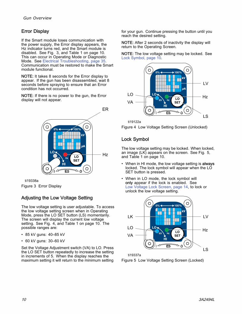
Error Display
If the Smart module loses communication withthe power supply, the Error display appears, theHz indicator turns red, and the Smart module isdisabled. See Fig. 3, and Table 1 on page 10.This can occur in Operating Mode or DiagnosticMode. See Electrical Troubleshooting, page 35.Communication must be restored to make the Smartmodule functional.NOTE: It takes 8 seconds for the Error display toappear. If the gun has been disassembled, wait 8seconds before spraying to ensure that an Errorcondition has not occurred.NOTE: If there is no power to the gun, the Errordisplay will not appear.
Figure 3 Error Display
Adjusting the Low Voltage Setting
The low voltage setting is user adjustable. To accessthe low voltage setting screen when in OperatingMode, press the LO SET button (LS) momentarily.The screen will display the current low voltagesetting. See Fig. 4, and Table 1 on page 10. Thepossible ranges are:• 85 kV guns: 40–85 kV• 60 kV guns: 30–60 kVSet the Voltage Adjustment switch (VA) to LO. Pressthe LO SET button repeatedly to increase the settingin increments of 5. When the display reaches themaximum setting it will return to the minimum setting
for your gun. Continue pressing the button until youreach the desired setting.
NOTE: After 2 seconds of inactivity the display willreturn to the Operating Screen.
NOTE: The low voltage setting may be locked. SeeLock Symbol, page 10.
Figure 4 Low Voltage Setting Screen (Unlocked)
Lock Symbol
The low voltage setting may be locked. When locked,an image (LK) appears on the screen. See Fig. 5,and Table 1 on page 10.
• When in HI mode, the low voltage setting is alwayslocked. The lock symbol will appear when the LOSET button is pressed.
• When in LO mode, the lock symbol willonly appear if the lock is enabled. SeeLow Voltage Lock Screen, page 14, to lock orunlock the low voltage setting.
Figure 5 Low Voltage Setting Screen (Locked)
10 3A2494L
Gun Overview
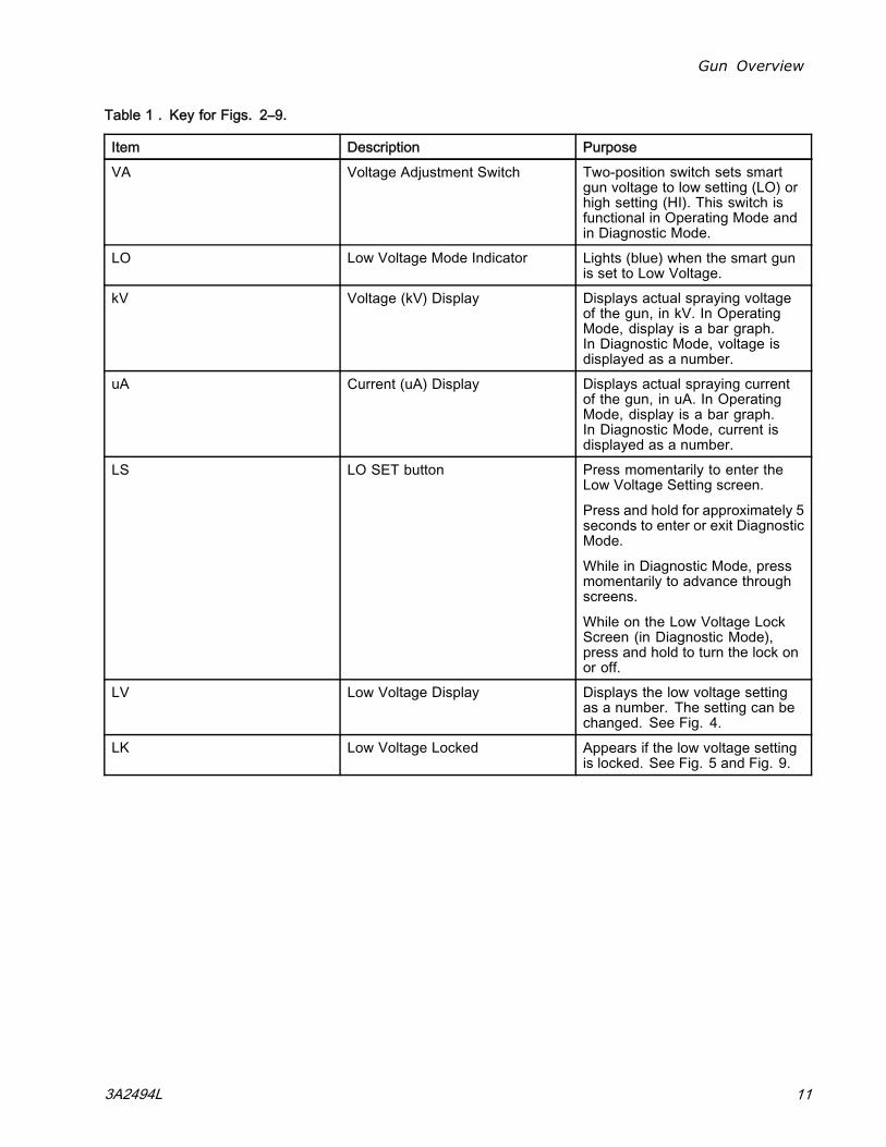
Table 1 . Key for Figs. 2–9.
Item Description PurposeVA Voltage Adjustment Switch Two-position switch sets smart
gun voltage to low setting (LO) orhigh setting (HI). This switch isfunctional in Operating Mode andin Diagnostic Mode.
LO Low Voltage Mode Indicator Lights (blue) when the smart gunis set to Low Voltage.
kV Voltage (kV) Display Displays actual spraying voltageof the gun, in kV. In OperatingMode, display is a bar graph.In Diagnostic Mode, voltage isdisplayed as a number.
uA Current (uA) Display Displays actual spraying currentof the gun, in uA. In OperatingMode, display is a bar graph.In Diagnostic Mode, current isdisplayed as a number.
LS LO SET button Press momentarily to enter theLow Voltage Setting screen.
Press and hold for approximately 5seconds to enter or exit DiagnosticMode.
While in Diagnostic Mode, pressmomentarily to advance throughscreens.
While on the Low Voltage LockScreen (in Diagnostic Mode),press and hold to turn the lock onor off.
LV Low Voltage Display Displays the low voltage settingas a number. The setting can bechanged. See Fig. 4.
LK Low Voltage Locked Appears if the low voltage settingis locked. See Fig. 5 and Fig. 9.
3A2494L 11
Gun Overview
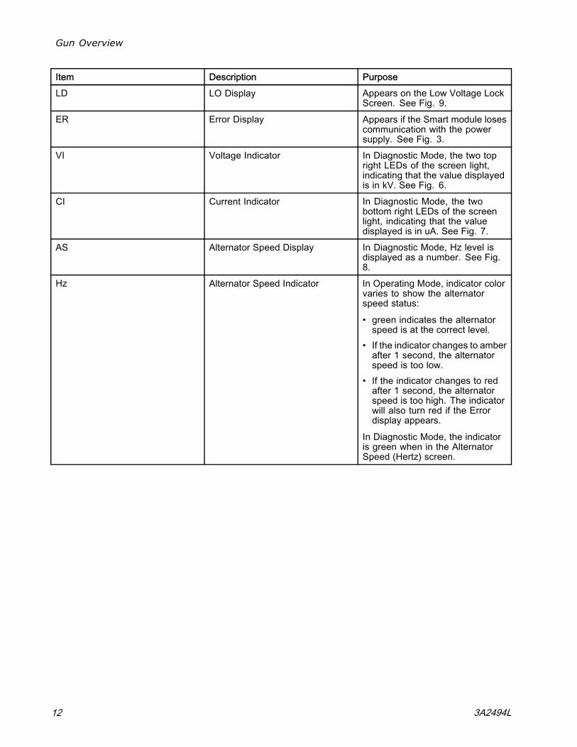
Item Description PurposeLD LO Display Appears on the Low Voltage Lock
Screen. See Fig. 9.ER Error Display Appears if the Smart module loses
communication with the powersupply. See Fig. 3.
VI Voltage Indicator In Diagnostic Mode, the two topright LEDs of the screen light,indicating that the value displayedis in kV. See Fig. 6.
CI Current Indicator In Diagnostic Mode, the twobottom right LEDs of the screenlight, indicating that the valuedisplayed is in uA. See Fig. 7.
AS Alternator Speed Display In Diagnostic Mode, Hz level isdisplayed as a number. See Fig.8.
Hz Alternator Speed Indicator In Operating Mode, indicator colorvaries to show the alternatorspeed status:
• green indicates the alternatorspeed is at the correct level.
• If the indicator changes to amberafter 1 second, the alternatorspeed is too low.
• If the indicator changes to redafter 1 second, the alternatorspeed is too high. The indicatorwill also turn red if the Errordisplay appears.
In Diagnostic Mode, the indicatoris green when in the AlternatorSpeed (Hertz) screen.
12 3A2494L
Gun Overview
Diagnostic Mode
Diagnostic Mode includes four screens which displaygun data:
• Voltage (kiloVolts) Screen• Current (microAmperes) Screen• Alternator Speed (Hertz) Screen• Low Voltage Lock Screen
NOTE: You must be in Operating Mode to adjust thelow voltage setting; the setting is not adjustable inDiagnostic Mode. However, the voltage adjustmentswitch (VA) can be set to HI or LO in Operating Modeand in Diagnostic Mode.
To enter Diagnostic Mode, press and hold the LO SET(LS) button for approximately 5 seconds. The displaywill go to the Voltage (kiloVolts) Screen, page 13.
To advance to the next screen, press the LO SETbutton again.
To exit Diagnostic Mode, press and hold the LO SETbutton for approximately 5 seconds. The screen willreturn to Operating Mode.
NOTE: If the gun is detriggered while in DiagnosticMode, the last screen viewed will be displayed whenthe gun is retriggered.
NOTE: Diagnostic Mode cannot be exitedfrom the Low Voltage Lock Screen. SeeLow Voltage Lock Screen, page 14 for details.
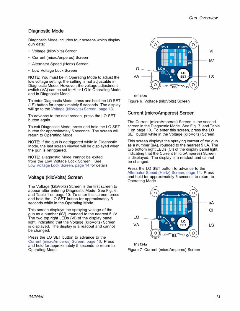
Voltage (kiloVolts) Screen
The Voltage (kiloVolts) Screen is the first screen toappear after entering Diagnostic Mode. See Fig. 6,and Table 1 on page 10. To enter this screen, pressand hold the LO SET button for approximately 5seconds while in the Operating Mode.
This screen displays the spraying voltage of thegun as a number (kV), rounded to the nearest 5 kV.The two top right LEDs (VI) of the display panellight, indicating that the Voltage (kiloVolts) Screenis displayed. The display is a readout and cannotbe changed.
Press the LO SET button to advance to theCurrent (microAmperes) Screen, page 13. Pressand hold for approximately 5 seconds to return toOperating Mode.
Figure 6 Voltage (kiloVolts) Screen
Current (microAmperes) Screen
The Current (microAmperes) Screen is the secondscreen in the Diagnostic Mode. See Fig. 7, and Table1 on page 10. To enter this screen, press the LOSET button while in the Voltage (kiloVolts) Screen.This screen displays the spraying current of the gunas a number (uA), rounded to the nearest 5 uA. Thetwo bottom right LEDs (CI) of the display panel light,indicating that the Current (microAmperes) Screenis displayed. The display is a readout and cannotbe changed.Press the LO SET button to advance to theAlternator Speed (Hertz) Screen, page 14. Pressand hold for approximately 5 seconds to return toOperating Mode.
Figure 7 Current (microAmperes) Screen
3A2494L 13
Gun Overview
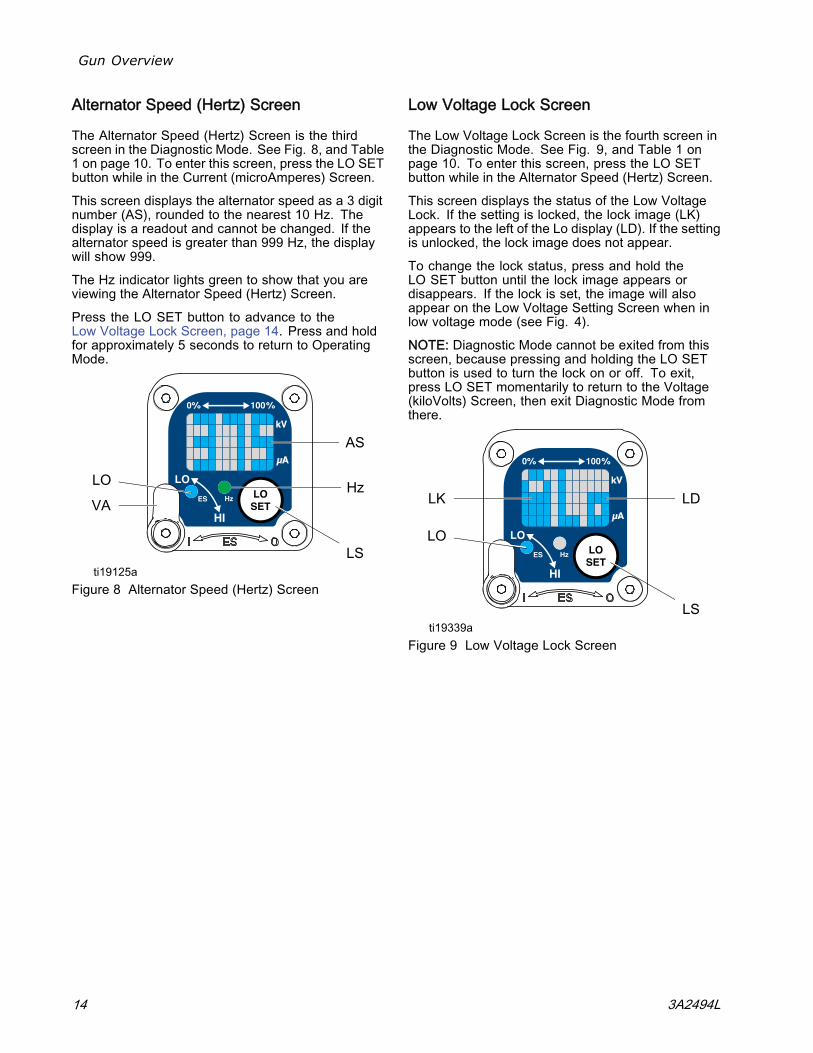
Alternator Speed (Hertz) Screen
The Alternator Speed (Hertz) Screen is the thirdscreen in the Diagnostic Mode. See Fig. 8, and Table1 on page 10. To enter this screen, press the LO SETbutton while in the Current (microAmperes) Screen.
This screen displays the alternator speed as a 3 digitnumber (AS), rounded to the nearest 10 Hz. Thedisplay is a readout and cannot be changed. If thealternator speed is greater than 999 Hz, the displaywill show 999.
The Hz indicator lights green to show that you areviewing the Alternator Speed (Hertz) Screen.
Press the LO SET button to advance to theLow Voltage Lock Screen, page 14. Press and holdfor approximately 5 seconds to return to OperatingMode.
Figure 8 Alternator Speed (Hertz) Screen
Low Voltage Lock Screen
The Low Voltage Lock Screen is the fourth screen inthe Diagnostic Mode. See Fig. 9, and Table 1 onpage 10. To enter this screen, press the LO SETbutton while in the Alternator Speed (Hertz) Screen.
This screen displays the status of the Low VoltageLock. If the setting is locked, the lock image (LK)appears to the left of the Lo display (LD). If the settingis unlocked, the lock image does not appear.
To change the lock status, press and hold theLO SET button until the lock image appears ordisappears. If the lock is set, the image will alsoappear on the Low Voltage Setting Screen when inlow voltage mode (see Fig. 4).
NOTE: Diagnostic Mode cannot be exited from thisscreen, because pressing and holding the LO SETbutton is used to turn the lock on or off. To exit,press LO SET momentarily to return to the Voltage(kiloVolts) Screen, then exit Diagnostic Mode fromthere.
Figure 9 Low Voltage Lock Screen
14 3A2494L
Installation
Installation
Installing and servicing this equipment requiresaccess to parts which may cause electric shockor other serious injury if work is not performedproperly.
• Do not install or service this equipment unlessyou are trained and qualified.
• Be sure your installation complies with local,state, and national codes for the installationof electrical apparatus in a Class I, Div. I,Hazardous Location or a Group II, Zone IExplosive Atmosphere Location.
• Comply with all applicable local, state, andnational fire, electrical, and other safetyregulations.
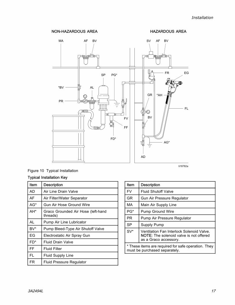
Fig. 10 shows a typical electrostatic air spray system.It is not an actual system design. For assistancein designing a system to suit your particular needs,contact your Graco distributor.
Warning Sign
Mount warning signs in the spray area where theycan easily be seen and read by all operators. AnEnglish Warning Sign is provided with the gun.
Ventilate the Spray Booth
Provide fresh air ventilation to reduce the risk of fireor explosion caused by the buildup of flammable ortoxic vapors when spraying, flushing, or cleaningthe gun. Do not operate the gun unless ventilationairflow is above the minimum requirement for localstandards.
Electrically interlock the gun air and fluid supplywith the ventilators to prevent gun operation withoutventilation airflow above the minimum requirementfor local standards. Check and follow all local, state,and national codes regarding air exhaust velocityrequirements. Verify the operation of the interlock atleast once per year.
High velocity air exhaust will decrease the operatingefficiency of the electrostatic system. Air exhaustvelocity of 100 ft/min (31 linear meters/minute) shouldbe sufficient.
3A2494L 15
Installation
Air Supply Line
To reduce the risk of electric shock, the air supplyhose must be electrically connected to a true earthground. Use only Graco Grounded Air SupplyHose.
1. See Fig. 10. Use the Graco Grounded Air SupplyHose (AH) to supply air to the gun. The gun airinlet fitting has a left-hand thread. The air supplyhose ground wire (AG) must be connected to atrue earth ground. Do not connect the air supplyhose to the gun air inlet yet.
2. Install an air line filter/water separator (AF) on thegun air line to ensure a dry, clean air supply to thegun. Dirt and moisture can ruin the appearanceof your finished workpiece and can cause thegun to malfunction.
3. Install bleed-type air regulators (PR, GR) onthe pump and gun air supply lines to control airpressure to the pump and gun.
Trapped air can cause the pump to cycleunexpectedly, which can result in seriousinjury, including splashing fluid in the eyes oron the skin. Do not operate the equipmentwithout the bleed-type air valve (BV) installed.
4. Install a bleed-type air valve (BV) on the pumpair supply line. The bleed-type air valve (BV) isrequired in your system to shut off air to the pumpand relieve air trapped between the valve andthe pump after the air regulator is shut off. Installan additional bleed-type air valve on the main airline (MA) to isolate the accessories for servicing.
5. Install an air bleed valve (BV) on each gun airsupply line to shut off air to the gun(s) and relieveair trapped between the valve and the gun afterthe air regulator is shut off.
Fluid Supply Line
1. Blow out the fluid line (FL) with air and flush itwith solvent. Use solvent which is compatiblewith the fluid to be sprayed. Do not connect thefluid supply line to the gun fluid inlet yet.
2. Install a fluid regulator (FR) on the fluid line tocontrol fluid pressure to the gun.
3. Install a fluid filter (FF) near the pump outlet, toremove particles and sediment which could clogthe spray nozzle.
To reduce the risk of serious injury, includingsplashing fluid in the eyes or on the skin, donot operate equipment without the fluid drainvalve (FD) installed.
4. The fluid drain valve (FD) is required in yoursystem to assist in relieving fluid pressure in thedisplacement pump, hose, and gun. Triggeringthe gun to relieve pressure may not be sufficient.Install a drain valve close to the pump's fluidoutlet.
16 3A2494L
Installation
NON-HAZARDOUS AREA HAZARDOUS AREA
Figure 10 Typical Installation
Typical Installation Key
Item DescriptionAD Air Line Drain ValveAF Air Filter/Water SeparatorAG* Gun Air Hose Ground WireAH* Graco Grounded Air Hose (left-hand
threads)AL Pump Air Line LubricatorBV* Pump Bleed-Type Air Shutoff ValveEG Electrostatic Air Spray GunFD* Fluid Drain ValveFF Fluid FilterFL Fluid Supply LineFR Fluid Pressure Regulator
Item DescriptionFV Fluid Shutoff ValveGR Gun Air Pressure RegulatorMA Main Air Supply LinePG* Pump Ground WirePR Pump Air Pressure RegulatorSP Supply PumpSV* Ventilation Fan Interlock Solenoid Valve.
NOTE: The solenoid valve is not offeredas a Graco accessory.
* These items are required for safe operation. Theymust be purchased separately.
3A2494L 17
Gun Setup
Gun Setup
Gun Setup Checklist
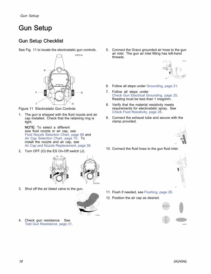
See Fig. 11 to locate the electrostatic gun controls.
Figure 11 Electrostatic Gun Controls1. The gun is shipped with the fluid nozzle and air
cap installed. Check that the retaining ring istight.NOTE: To select a differentsize fluid nozzle or air cap, seeFluid Nozzle Selection Chart, page 68 andAir Cap Selection Chart, page 70. Toinstall the nozzle and air cap, seeAir Cap and Nozzle Replacement, page 38.
2. Turn OFF (O) the ES On-Off switch (J).
3. Shut off the air bleed valve to the gun.
4. Check gun resistance. SeeTest Gun Resistance, page 31.
5. Connect the Graco grounded air hose to the gunair inlet. The gun air inlet fitting has left-handthreads.
6. Follow all steps under Grounding, page 21.7. Follow all steps under
Check Gun Electrical Grounding, page 25.Reading must be less than 1 megohm.
8. Verify that the material resistivity meetsrequirements for electrostatic spray. SeeCheck Fluid Resistivity, page 26.
9. Connect the exhaust tube and secure with theclamp provided.
10. Connect the fluid hose to the gun fluid inlet.
11. Flush if needed, see Flushing, page 28.12. Position the air cap as desired.
18 3A2494L
Gun Setup
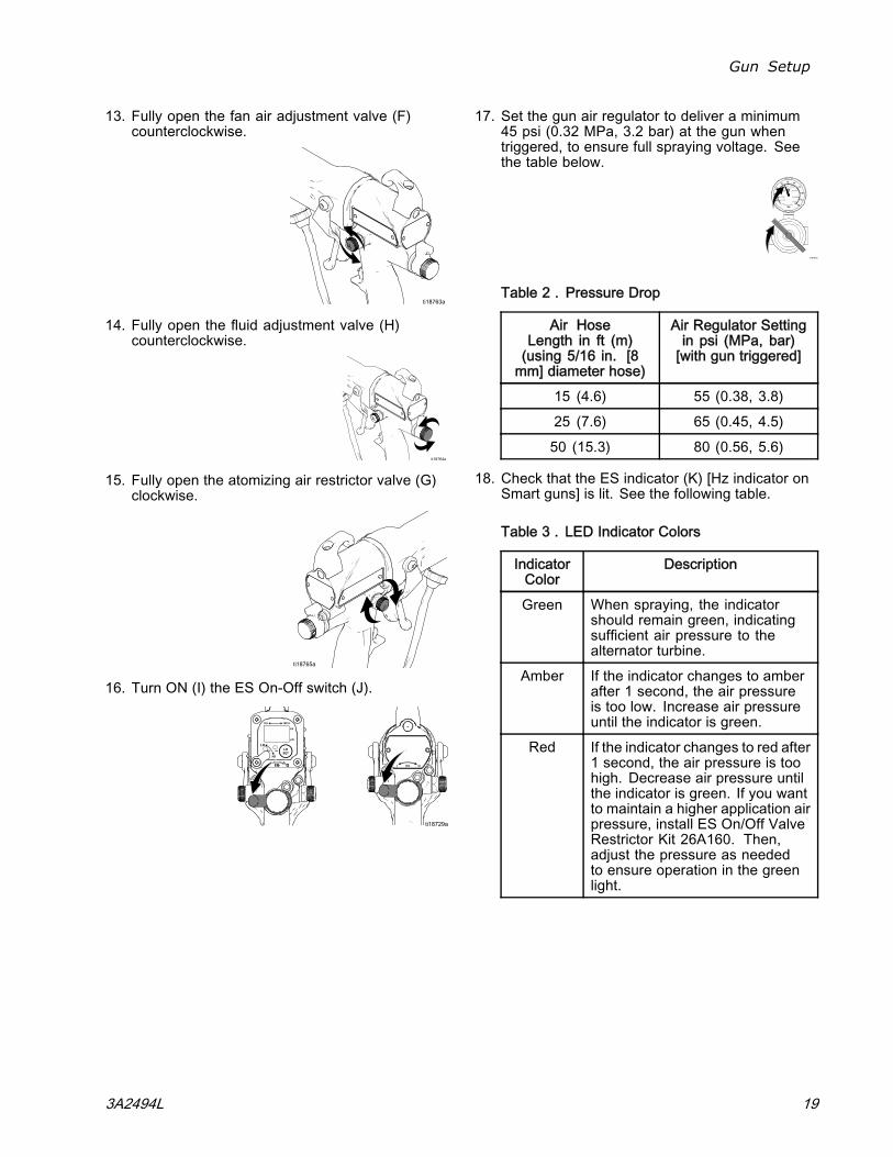
13. Fully open the fan air adjustment valve (F)counterclockwise.
14. Fully open the fluid adjustment valve (H)counterclockwise.
15. Fully open the atomizing air restrictor valve (G)clockwise.
16. Turn ON (I) the ES On-Off switch (J).
17. Set the gun air regulator to deliver a minimum45 psi (0.32 MPa, 3.2 bar) at the gun whentriggered, to ensure full spraying voltage. Seethe table below.
Table 2 . Pressure Drop
Air HoseLength in ft (m)(using 5/16 in. [8mm] diameter hose)
Air Regulator Settingin psi (MPa, bar)[with gun triggered]
15 (4.6) 55 (0.38, 3.8)25 (7.6) 65 (0.45, 4.5)50 (15.3) 80 (0.56, 5.6)
18. Check that the ES indicator (K) [Hz indicator onSmart guns] is lit. See the following table.
Table 3 . LED Indicator Colors
IndicatorColor
Description
Green When spraying, the indicatorshould remain green, indicatingsufficient air pressure to thealternator turbine.
Amber If the indicator changes to amberafter 1 second, the air pressureis too low. Increase air pressureuntil the indicator is green.
Red If the indicator changes to red after1 second, the air pressure is toohigh. Decrease air pressure untilthe indicator is green. If you wantto maintain a higher application airpressure, install ES On/Off ValveRestrictor Kit 26A160. Then,adjust the pressure as neededto ensure operation in the greenlight.
3A2494L 19
Gun Setup
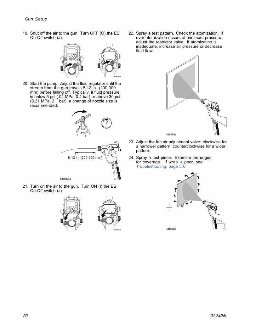
19. Shut off the air to the gun. Turn OFF (O) the ESOn-Off switch (J).
20. Start the pump. Adjust the fluid regulator until thestream from the gun travels 8-12 in. (200-300mm) before falling off. Typically, if fluid pressureis below 5 psi (.04 MPa, 0.4 bar) or above 30 psi(0.21 MPa, 2.1 bar), a change of nozzle size isrecommended.
21. Turn on the air to the gun. Turn ON (I) the ESOn-Off switch (J).
22. Spray a test pattern. Check the atomization. Ifover-atomization occurs at minimum pressure,adjust the restrictor valve. If atomization isinadequate, increase air pressure or decreasefluid flow.
23. Adjust the fan air adjustment valve: clockwise fora narrower pattern, counterclockwise for a widerpattern.
24. Spray a test piece. Examine the edgesfor coverage. If wrap is poor, seeTroubleshooting, page 33.
20 3A2494L
Gun Setup
Grounding
When operating the electrostatic gun, anyungrounded objects in the spray area (people,containers, tools, etc.) can become electricallycharged. Improper grounding can result in staticsparking, which can cause a fire, explosion, orelectric shock. Ground all equipment, personnel,object being sprayed, and conductive objectsin or close to the spray area. Resistance mustnot exceed 1 megohm. Follow the groundinginstructions below.
The following are minimum grounding requirementsfor a basic electrostatic system (see Figs. 12–15).Your system may include other equipment or objectswhich must be grounded. Check your local electricalcode for detailed grounding instructions. Your systemmust be connected to a true earth ground.
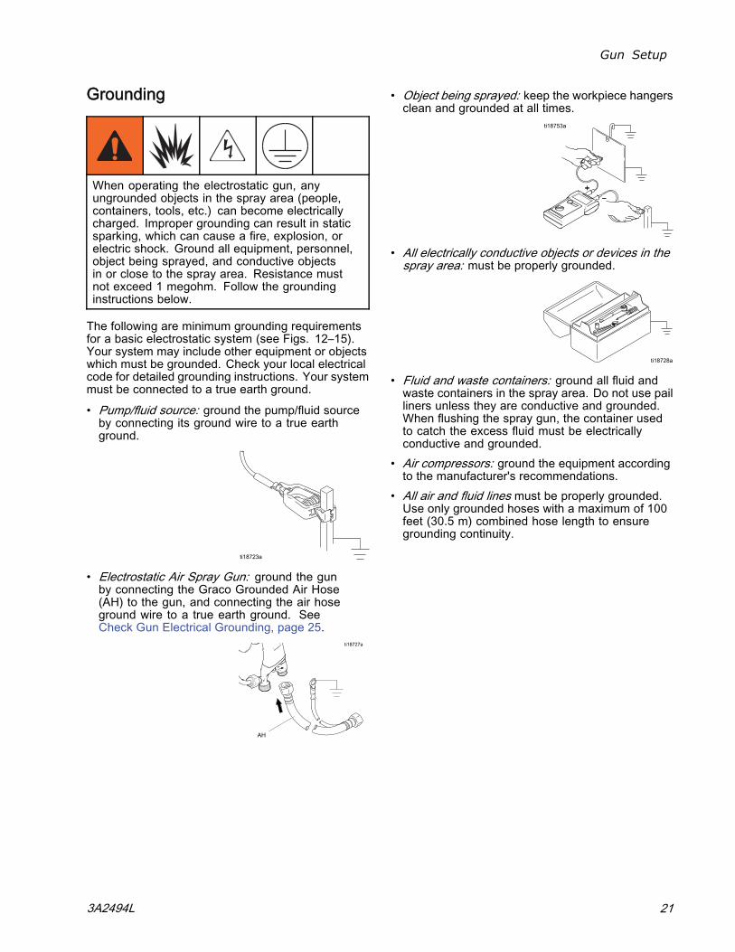
• Pump/fluid source: ground the pump/fluid sourceby connecting its ground wire to a true earthground.
• Electrostatic Air Spray Gun: ground the gunby connecting the Graco Grounded Air Hose(AH) to the gun, and connecting the air hoseground wire to a true earth ground. SeeCheck Gun Electrical Grounding, page 25.
• Object being sprayed: keep the workpiece hangersclean and grounded at all times.
• All electrically conductive objects or devices in thespray area: must be properly grounded.
• Fluid and waste containers: ground all fluid andwaste containers in the spray area. Do not use pailliners unless they are conductive and grounded.When flushing the spray gun, the container usedto catch the excess fluid must be electricallyconductive and grounded.
• Air compressors: ground the equipment accordingto the manufacturer's recommendations.
• All air and fluid lines must be properly grounded.Use only grounded hoses with a maximum of 100feet (30.5 m) combined hose length to ensuregrounding continuity.
3A2494L 21
Gun Setup
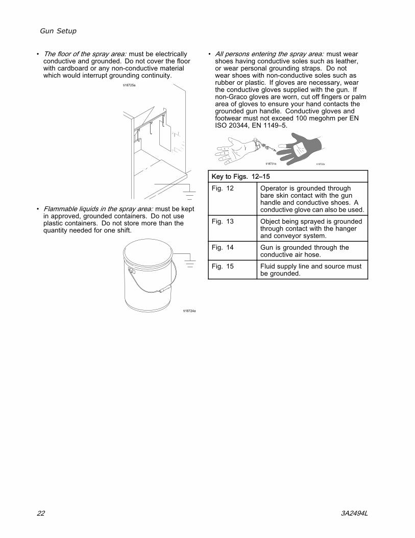
• The floor of the spray area: must be electricallyconductive and grounded. Do not cover the floorwith cardboard or any non-conductive materialwhich would interrupt grounding continuity.
• Flammable liquids in the spray area: must be keptin approved, grounded containers. Do not useplastic containers. Do not store more than thequantity needed for one shift.
• All persons entering the spray area: must wearshoes having conductive soles such as leather,or wear personal grounding straps. Do notwear shoes with non-conductive soles such asrubber or plastic. If gloves are necessary, wearthe conductive gloves supplied with the gun. Ifnon-Graco gloves are worn, cut off fingers or palmarea of gloves to ensure your hand contacts thegrounded gun handle. Conductive gloves andfootwear must not exceed 100 megohm per ENISO 20344, EN 1149–5.
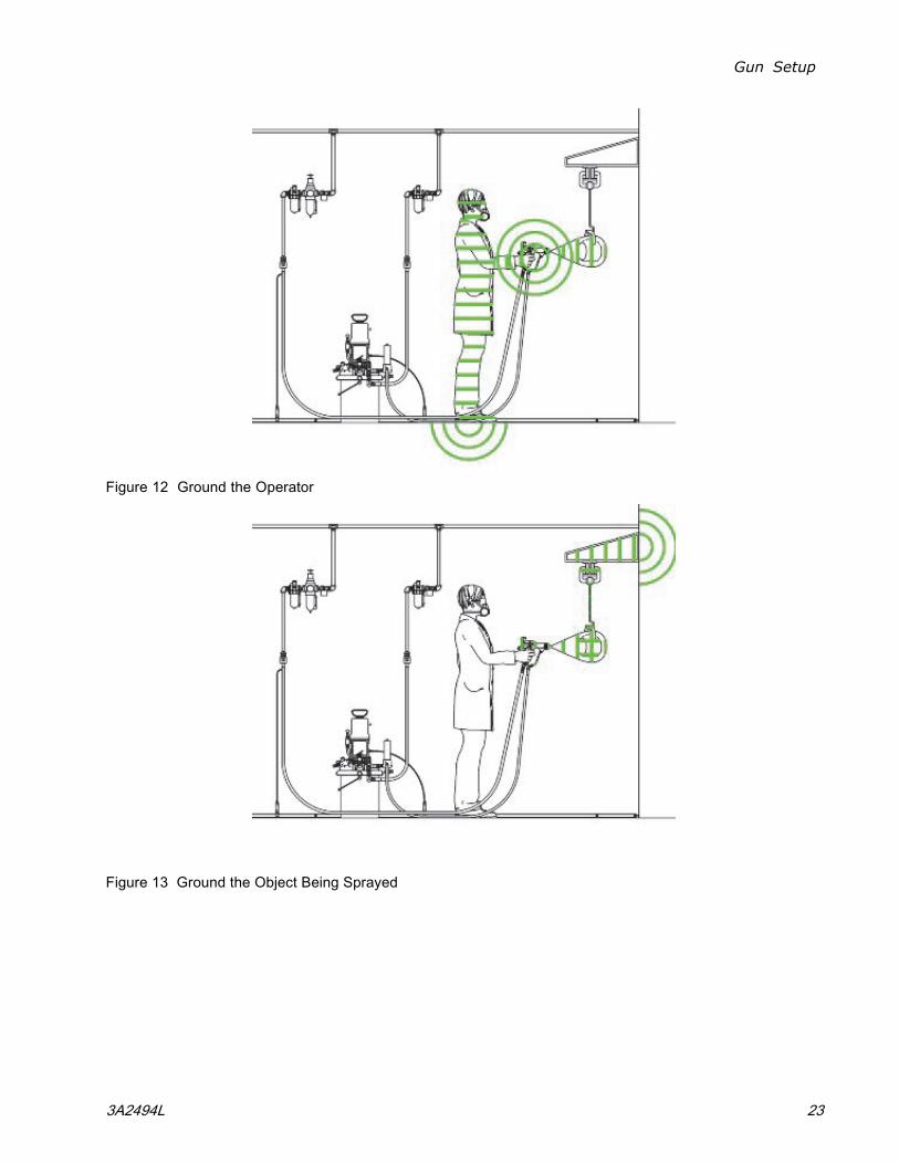
Key to Figs. 12–15Fig. 12 Operator is grounded through
bare skin contact with the gunhandle and conductive shoes. Aconductive glove can also be used.
Fig. 13 Object being sprayed is groundedthrough contact with the hangerand conveyor system.
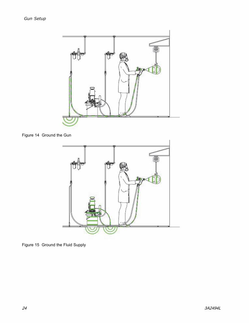
Fig. 14 Gun is grounded through theconductive air hose.
Fig. 15 Fluid supply line and source mustbe grounded.
22 3A2494L
Gun Setup
Figure 12 Ground the Operator
Figure 13 Ground the Object Being Sprayed
3A2494L 23
Gun Setup
Figure 14 Ground the Gun
Figure 15 Ground the Fluid Supply
24 3A2494L
Gun Setup
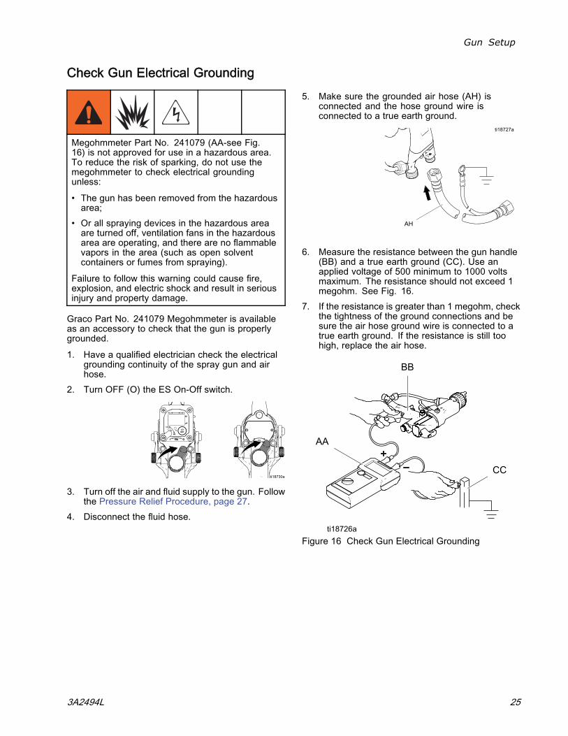
Check Gun Electrical Grounding
Megohmmeter Part No. 241079 (AA-see Fig.16) is not approved for use in a hazardous area.To reduce the risk of sparking, do not use themegohmmeter to check electrical groundingunless:
• The gun has been removed from the hazardousarea;
• Or all spraying devices in the hazardous areaare turned off, ventilation fans in the hazardousarea are operating, and there are no flammablevapors in the area (such as open solventcontainers or fumes from spraying).
Failure to follow this warning could cause fire,explosion, and electric shock and result in seriousinjury and property damage.
Graco Part No. 241079 Megohmmeter is availableas an accessory to check that the gun is properlygrounded.
1. Have a qualified electrician check the electricalgrounding continuity of the spray gun and airhose.
2. Turn OFF (O) the ES On-Off switch.
3. Turn off the air and fluid supply to the gun. Followthe Pressure Relief Procedure, page 27.
4. Disconnect the fluid hose.
5. Make sure the grounded air hose (AH) isconnected and the hose ground wire isconnected to a true earth ground.
6. Measure the resistance between the gun handle(BB) and a true earth ground (CC). Use anapplied voltage of 500 minimum to 1000 voltsmaximum. The resistance should not exceed 1megohm. See Fig. 16.
7. If the resistance is greater than 1 megohm, checkthe tightness of the ground connections and besure the air hose ground wire is connected to atrue earth ground. If the resistance is still toohigh, replace the air hose.
Figure 16 Check Gun Electrical Grounding
3A2494L 25

Gun Setup
Check Fluid Resistivity
To reduce the risk of fire, explosion, or electricshock, check the fluid resistivity in a non-hazardousarea only. Resistance Meter 722886 and Probe722860 are not approved for use in a hazardousarea.
Failure to follow this warning could cause fire,explosion, or electric shock and result in seriousinjury and property damage.
Graco Part No. 722886 Resistance Meter and722860 Probe are available as accessories to checkthat the resistivity of the fluid being sprayed meetsthe requirements of an electrostatic air spray system.
Follow the instructions included with the meterand probe. Readings of 20 megohms-cm andabove provide the best electrostatic results and arerecommended.
A high conductivity kit or high conductivity hose maybe required for readings less than 20 megohm-cm.
Table 4 . Fluid Resistivity Levels
Megohms-cm1–7 7–20 20–200 200–2000
High Con-ductivityKit recom-mended
High Con-ductivityKit may beneeded
Best elec-trostaticresults
Good elec-trostaticresults
Check Fluid Viscosity
To check fluid viscosity you will need:
• a viscosity cup• a stopwatch.
1. Completely submerge the viscosity cup inthe fluid. Lift the cup out quickly, starting thestopwatch as soon as the cup is completelyremoved.
2. Watch the stream of fluid coming from the bottomof the cup. As soon as there is a break in thestream, shut off the stopwatch.
3. Record the fluid type, elapsed time, and size ofthe viscosity cup.
4. If the viscosity is too high or too low, contact thematerial supplier. Adjust as necessary.
Flush Before Using EquipmentThe equipment was tested in fluid at the factory. Toavoid contaminating your fluid, flush the equipmentwith a compatible solvent before using the equipment.
Guidelines for Abrasive MaterialsWhen spraying abrasive materials, follow theseguidelines:
• Order Part No. 24N704 Electrode (blue) forabrasive materials.
• Size the nozzle properly to reduce fluid pressurebelow 30 psi (0.21 MPa, 2.1 bar), producing an8–12 in. (200–300 mm) fluid stream.
• Operate the gun with the fluid adjustment knob inthe full flow position at all times. Use an externalfluid regulator, not the fluid adjustment knob, to setthe fluid pressure.
• Use the minimum atomizing and fan air pressurespossible to achieve a good pattern.
• Follow all procedures underClean the Gun Daily, page 29.
• Inspect the electrode daily and replace if damaged.See Electrode Replacement, page 39.
26 3A2494L
Operation
Operation
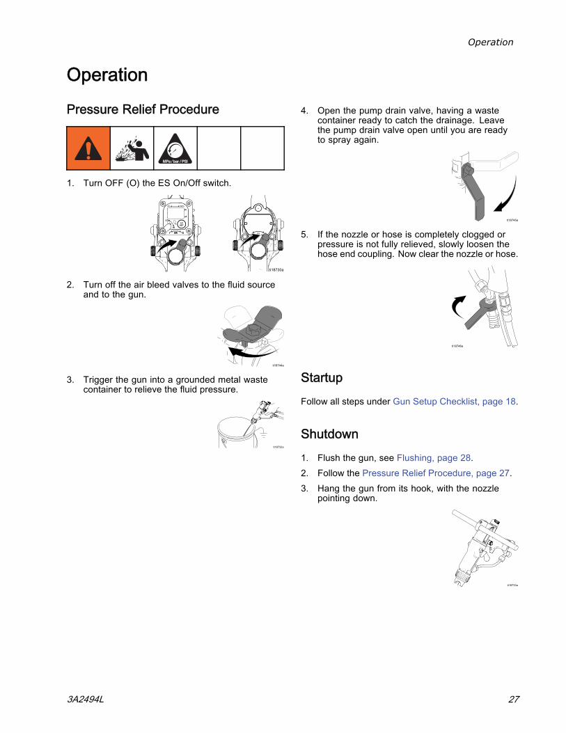
Pressure Relief Procedure
1. Turn OFF (O) the ES On/Off switch.
2. Turn off the air bleed valves to the fluid sourceand to the gun.
3. Trigger the gun into a grounded metal wastecontainer to relieve the fluid pressure.
4. Open the pump drain valve, having a wastecontainer ready to catch the drainage. Leavethe pump drain valve open until you are readyto spray again.
5. If the nozzle or hose is completely clogged orpressure is not fully relieved, slowly loosen thehose end coupling. Now clear the nozzle or hose.
StartupFollow all steps under Gun Setup Checklist, page 18.
Shutdown1. Flush the gun, see Flushing, page 28.2. Follow the Pressure Relief Procedure, page 27.3. Hang the gun from its hook, with the nozzle
pointing down.
3A2494L 27
Maintenance
Maintenance
Flushing
• Flush before changing fluids, before fluid can dryin the equipment, at the end of the day, beforestoring, and before repairing equipment.
• Flush at the lowest pressure possible. Checkconnectors for leaks and tighten as necessary.
• Flush with a fluid that is compatible with the fluidbeing dispensed and the equipment wetted parts.
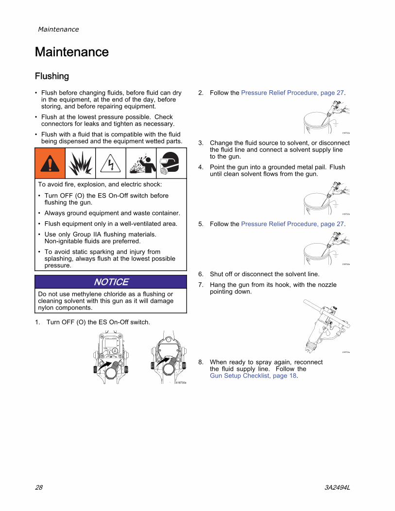
To avoid fire, explosion, and electric shock:
• Turn OFF (O) the ES On-Off switch beforeflushing the gun.
• Always ground equipment and waste container.• Flush equipment only in a well-ventilated area.• Use only Group IIA flushing materials.Non-ignitable fluids are preferred.
• To avoid static sparking and injury fromsplashing, always flush at the lowest possiblepressure.
NOTICEDo not use methylene chloride as a flushing orcleaning solvent with this gun as it will damagenylon components.
1. Turn OFF (O) the ES On-Off switch.
2. Follow the Pressure Relief Procedure, page 27.
3. Change the fluid source to solvent, or disconnectthe fluid line and connect a solvent supply lineto the gun.
4. Point the gun into a grounded metal pail. Flushuntil clean solvent flows from the gun.
5. Follow the Pressure Relief Procedure, page 27.
6. Shut off or disconnect the solvent line.7. Hang the gun from its hook, with the nozzle
pointing down.
8. When ready to spray again, reconnectthe fluid supply line. Follow theGun Setup Checklist, page 18.
28 3A2494L
Maintenance
Clean the Gun Daily
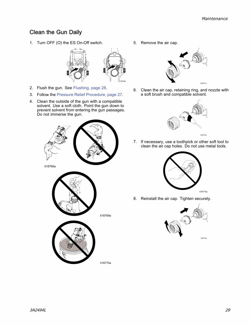
1. Turn OFF (O) the ES On-Off switch.
2. Flush the gun. See Flushing, page 28.3. Follow the Pressure Relief Procedure, page 27.4. Clean the outside of the gun with a compatible
solvent. Use a soft cloth. Point the gun down toprevent solvent from entering the gun passages.Do not immerse the gun.
5. Remove the air cap.
6. Clean the air cap, retaining ring, and nozzle witha soft brush and compatible solvent.
7. If necessary, use a toothpick or other soft tool toclean the air cap holes. Do not use metal tools.
8. Reinstall the air cap. Tighten securely.
3A2494L 29
Maintenance
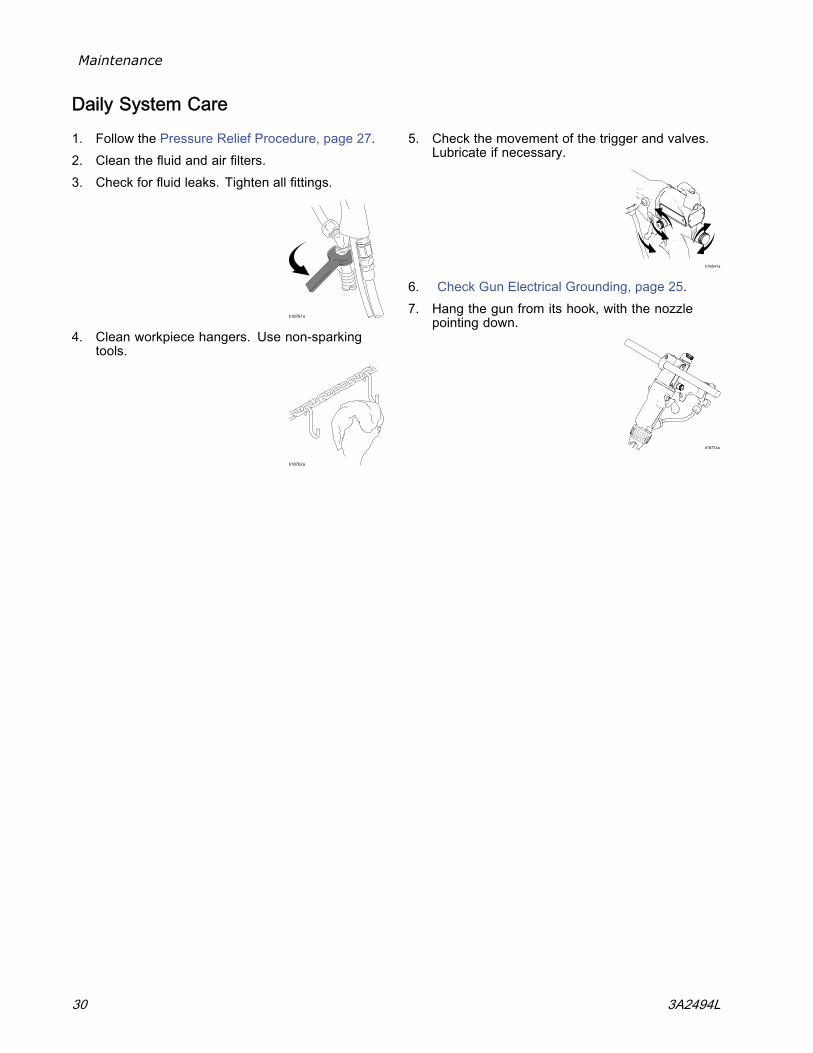
Daily System Care
1. Follow the Pressure Relief Procedure, page 27.2. Clean the fluid and air filters.3. Check for fluid leaks. Tighten all fittings.
4. Clean workpiece hangers. Use non-sparkingtools.
5. Check the movement of the trigger and valves.Lubricate if necessary.
6. Check Gun Electrical Grounding, page 25.7. Hang the gun from its hook, with the nozzle
pointing down.
30 3A2494L
Electrical Tests
Electrical TestsUse the following procedures to test the conditionof the power supply and gun body, and electricalcontinuity between components.
Use megohmmeter Part No. 241079 (AA) and anapplied voltage of 500 V. Connect the leads asshown.
Megohmmeter Part No. 241079 (AA-see Fig.17) is not approved for use in a hazardous area.To reduce the risk of sparking, do not use themegohmmeter to check electrical groundingunless:
• The gun has been removed from the hazardousarea;
• Or all spraying devices in the hazardous areaare turned off, ventilation fans in the hazardousarea are operating, and there are no flammablevapors in the area (such as open solventcontainers or fumes from spraying).
Failure to follow this warning could cause fire,explosion, and electric shock and result in seriousinjury and property damage.
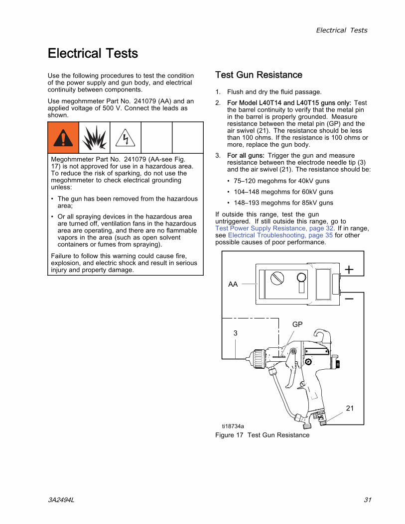
Test Gun Resistance
1. Flush and dry the fluid passage.2. For Model L40T14 and L40T15 guns only: Test
the barrel continuity to verify that the metal pinin the barrel is properly grounded. Measureresistance between the metal pin (GP) and theair swivel (21). The resistance should be lessthan 100 ohms. If the resistance is 100 ohms ormore, replace the gun body.
3. For all guns: Trigger the gun and measureresistance between the electrode needle tip (3)and the air swivel (21). The resistance should be:
• 75–120 megohms for 40kV guns• 104–148 megohms for 60kV guns• 148–193 megohms for 85kV guns
If outside this range, test the gununtriggered. If still outside this range, go toTest Power Supply Resistance, page 32. If in range,see Electrical Troubleshooting, page 35 for otherpossible causes of poor performance.
Figure 17 Test Gun Resistance
3A2494L 31
Electrical Tests
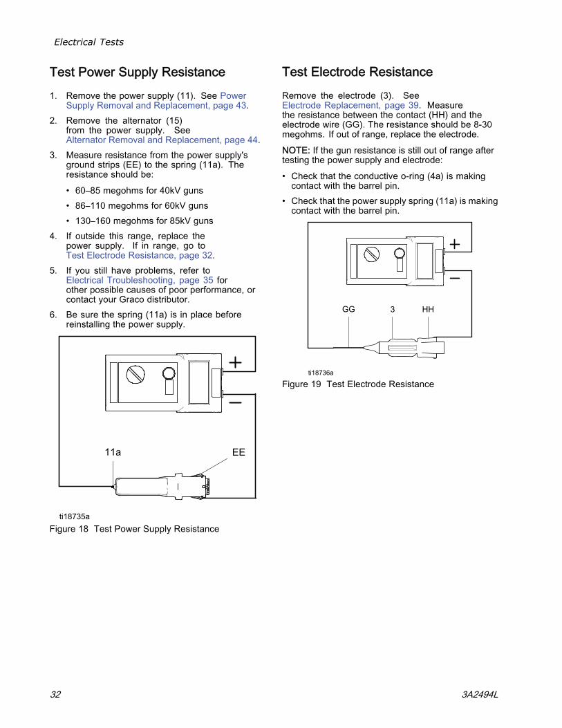
Test Power Supply Resistance
1. Remove the power supply (11). See PowerSupply Removal and Replacement, page 43.
2. Remove the alternator (15)from the power supply. SeeAlternator Removal and Replacement, page 44.
3. Measure resistance from the power supply'sground strips (EE) to the spring (11a). Theresistance should be:
• 60–85 megohms for 40kV guns• 86–110 megohms for 60kV guns• 130–160 megohms for 85kV guns
4. If outside this range, replace thepower supply. If in range, go toTest Electrode Resistance, page 32.
5. If you still have problems, refer toElectrical Troubleshooting, page 35 forother possible causes of poor performance, orcontact your Graco distributor.
6. Be sure the spring (11a) is in place beforereinstalling the power supply.
Figure 18 Test Power Supply Resistance
Test Electrode Resistance
Remove the electrode (3). SeeElectrode Replacement, page 39. Measurethe resistance between the contact (HH) and theelectrode wire (GG). The resistance should be 8-30megohms. If out of range, replace the electrode.
NOTE: If the gun resistance is still out of range aftertesting the power supply and electrode:
• Check that the conductive o-ring (4a) is makingcontact with the barrel pin.
• Check that the power supply spring (11a) is makingcontact with the barrel pin.
Figure 19 Test Electrode Resistance
32 3A2494L
Troubleshooting
Troubleshooting
Installing and servicing this equipment requiresaccess to parts which may cause an electric shockor other serious injury if the work is not performedproperly. Do not install or repair this equipmentunless you are trained and qualified.
To reduce the risk of an injury, follow thePressure Relief Procedure, page 27, wheneveryou are instructed to relieve the pressure.
Check all possible remedies in the Troubleshooting Chart before disassembling the gun.
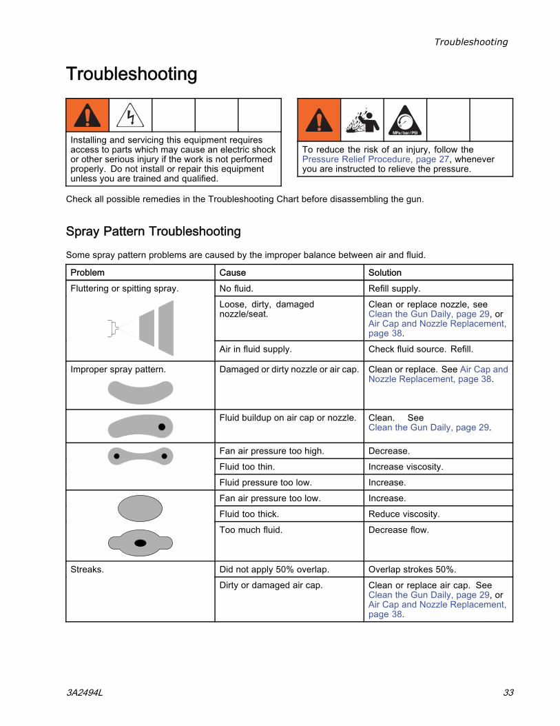
Spray Pattern Troubleshooting
Some spray pattern problems are caused by the improper balance between air and fluid.
Problem Cause SolutionNo fluid. Refill supply.Loose, dirty, damagednozzle/seat.
Clean or replace nozzle, seeClean the Gun Daily, page 29, orAir Cap and Nozzle Replacement,page 38.
Fluttering or spitting spray.
Air in fluid supply. Check fluid source. Refill.
Improper spray pattern. Damaged or dirty nozzle or air cap. Clean or replace. See Air Cap andNozzle Replacement, page 38.
Fluid buildup on air cap or nozzle. Clean. SeeClean the Gun Daily, page 29.
Fan air pressure too high. Decrease.Fluid too thin. Increase viscosity.Fluid pressure too low. Increase.Fan air pressure too low. Increase.Fluid too thick. Reduce viscosity.Too much fluid. Decrease flow.
Did not apply 50% overlap. Overlap strokes 50%.Streaks.Dirty or damaged air cap. Clean or replace air cap. See
Clean the Gun Daily, page 29, orAir Cap and Nozzle Replacement,page 38.
3A2494L 33
Troubleshooting
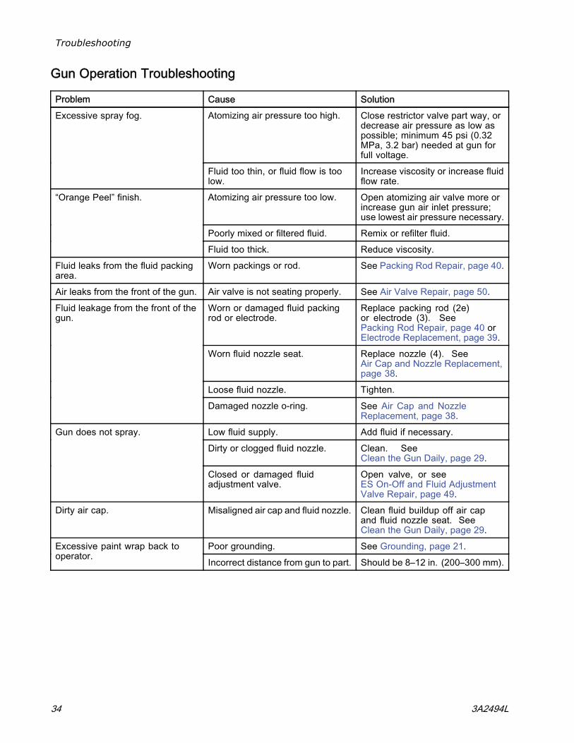
Gun Operation Troubleshooting
Problem Cause SolutionAtomizing air pressure too high. Close restrictor valve part way, or
decrease air pressure as low aspossible; minimum 45 psi (0.32MPa, 3.2 bar) needed at gun forfull voltage.
Excessive spray fog.
Fluid too thin, or fluid flow is toolow.
Increase viscosity or increase fluidflow rate.
Atomizing air pressure too low. Open atomizing air valve more orincrease gun air inlet pressure;use lowest air pressure necessary.
Poorly mixed or filtered fluid. Remix or refilter fluid.
“Orange Peel” finish.
Fluid too thick. Reduce viscosity.Fluid leaks from the fluid packingarea.
Worn packings or rod. See Packing Rod Repair, page 40.
Air leaks from the front of the gun. Air valve is not seating properly. See Air Valve Repair, page 50.Worn or damaged fluid packingrod or electrode.
Replace packing rod (2e)or electrode (3). SeePacking Rod Repair, page 40 orElectrode Replacement, page 39.
Worn fluid nozzle seat. Replace nozzle (4). SeeAir Cap and Nozzle Replacement,page 38.
Loose fluid nozzle. Tighten.
Fluid leakage from the front of thegun.
Damaged nozzle o-ring. See Air Cap and NozzleReplacement, page 38.
Low fluid supply. Add fluid if necessary.Dirty or clogged fluid nozzle. Clean. See
Clean the Gun Daily, page 29.
Gun does not spray.
Closed or damaged fluidadjustment valve.
Open valve, or seeES On-Off and Fluid AdjustmentValve Repair, page 49.
Dirty air cap. Misaligned air cap and fluid nozzle. Clean fluid buildup off air capand fluid nozzle seat. SeeClean the Gun Daily, page 29.
Poor grounding. See Grounding, page 21.Excessive paint wrap back tooperator. Incorrect distance from gun to part. Should be 8–12 in. (200–300 mm).
34 3A2494L
Troubleshooting
Electrical Troubleshooting
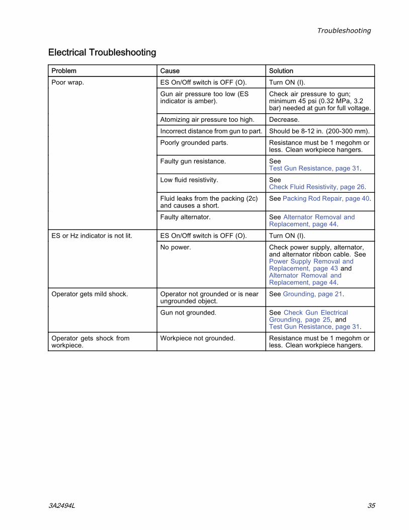
Problem Cause SolutionES On/Off switch is OFF (O). Turn ON (I).Gun air pressure too low (ESindicator is amber).
Check air pressure to gun;minimum 45 psi (0.32 MPa, 3.2bar) needed at gun for full voltage.
Atomizing air pressure too high. Decrease.Incorrect distance from gun to part. Should be 8-12 in. (200-300 mm).Poorly grounded parts. Resistance must be 1 megohm or
less. Clean workpiece hangers.Faulty gun resistance. See
Test Gun Resistance, page 31.Low fluid resistivity. See
Check Fluid Resistivity, page 26.Fluid leaks from the packing (2c)and causes a short.
See Packing Rod Repair, page 40.
Poor wrap.
Faulty alternator. See Alternator Removal andReplacement, page 44.
ES On/Off switch is OFF (O). Turn ON (I).ES or Hz indicator is not lit.No power. Check power supply, alternator,
and alternator ribbon cable. SeePower Supply Removal andReplacement, page 43 andAlternator Removal andReplacement, page 44.
Operator not grounded or is nearungrounded object.
See Grounding, page 21.Operator gets mild shock.
Gun not grounded. See Check Gun ElectricalGrounding, page 25, andTest Gun Resistance, page 31.
Operator gets shock fromworkpiece.
Workpiece not grounded. Resistance must be 1 megohm orless. Clean workpiece hangers.
3A2494L 35
Troubleshooting
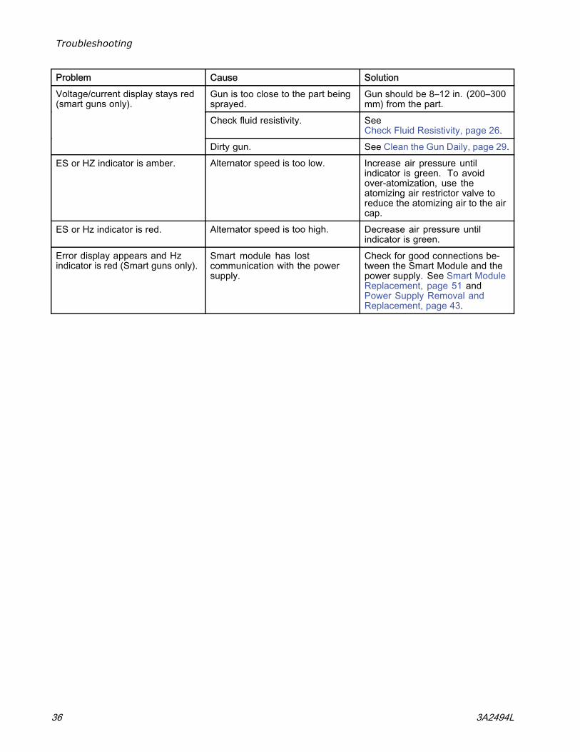
Problem Cause SolutionGun is too close to the part beingsprayed.
Gun should be 8–12 in. (200–300mm) from the part.
Check fluid resistivity. SeeCheck Fluid Resistivity, page 26.
Voltage/current display stays red(smart guns only).
Dirty gun. See Clean the Gun Daily, page 29.ES or HZ indicator is amber. Alternator speed is too low. Increase air pressure until
indicator is green. To avoidover-atomization, use theatomizing air restrictor valve toreduce the atomizing air to the aircap.
ES or Hz indicator is red. Alternator speed is too high. Decrease air pressure untilindicator is green.
Error display appears and Hzindicator is red (Smart guns only).
Smart module has lostcommunication with the powersupply.
Check for good connections be-tween the Smart Module and thepower supply. See Smart ModuleReplacement, page 51 andPower Supply Removal andReplacement, page 43.
36 3A2494L
Repair
Repair
Prepare the Gun for Service
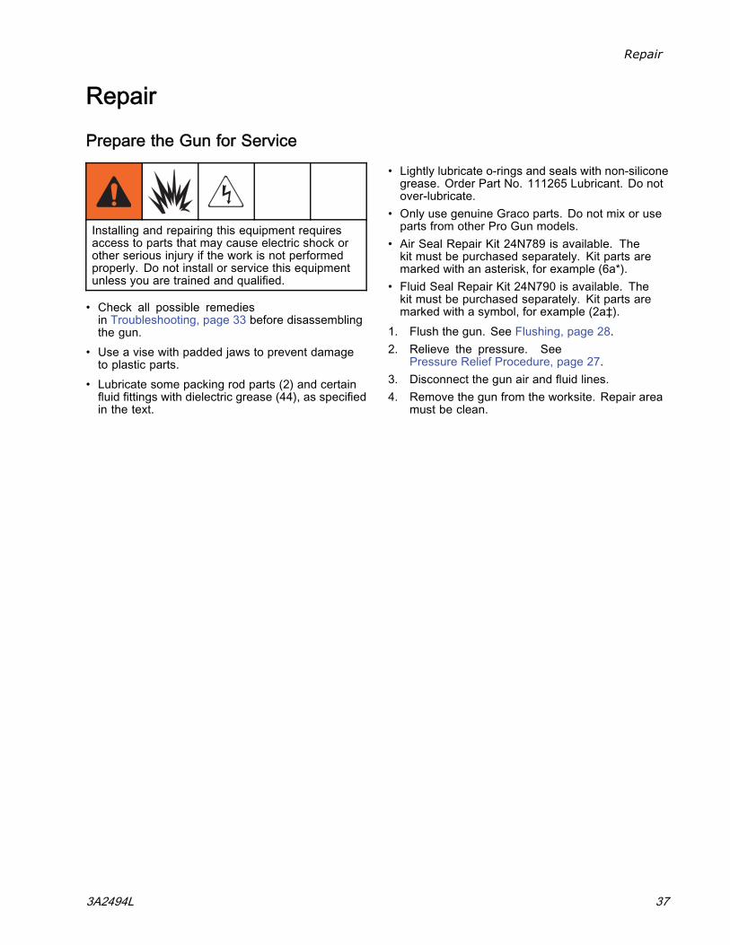
Installing and repairing this equipment requiresaccess to parts that may cause electric shock orother serious injury if the work is not performedproperly. Do not install or service this equipmentunless you are trained and qualified.
• Check all possible remediesin Troubleshooting, page 33 before disassemblingthe gun.
• Use a vise with padded jaws to prevent damageto plastic parts.
• Lubricate some packing rod parts (2) and certainfluid fittings with dielectric grease (44), as specifiedin the text.
• Lightly lubricate o-rings and seals with non-siliconegrease. Order Part No. 111265 Lubricant. Do notover-lubricate.
• Only use genuine Graco parts. Do not mix or useparts from other Pro Gun models.
• Air Seal Repair Kit 24N789 is available. Thekit must be purchased separately. Kit parts aremarked with an asterisk, for example (6a*).
• Fluid Seal Repair Kit 24N790 is available. Thekit must be purchased separately. Kit parts aremarked with a symbol, for example (2a‡).
1. Flush the gun. See Flushing, page 28.2. Relieve the pressure. See
Pressure Relief Procedure, page 27.3. Disconnect the gun air and fluid lines.4. Remove the gun from the worksite. Repair area
must be clean.
3A2494L 37
Repair
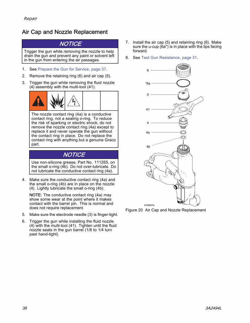
Air Cap and Nozzle Replacement
NOTICETrigger the gun while removing the nozzle to helpdrain the gun and prevent any paint or solvent leftin the gun from entering the air passages.
1. See Prepare the Gun for Service, page 37.2. Remove the retaining ring (6) and air cap (5).3. Trigger the gun while removing the fluid nozzle
(4) assembly with the multi-tool (41).
The nozzle contact ring (4a) is a conductivecontact ring, not a sealing o-ring. To reducethe risk of sparking or electric shock, do notremove the nozzle contact ring (4a) except toreplace it and never operate the gun withoutthe contact ring in place. Do not replace thecontact ring with anything but a genuine Gracopart.
NOTICEUse non-silicone grease, Part No. 111265, onthe small o-ring (4b). Do not over-lubricate. Donot lubricate the conductive contact ring (4a).
4. Make sure the conductive contact ring (4a) andthe small o-ring (4b) are in place on the nozzle(4). Lightly lubricate the small o-ring (4b).NOTE: The conductive contact ring (4a) mayshow some wear at the point where it makescontact with the barrel pin. This is normal anddoes not require replacement.
5. Make sure the electrode needle (3) is finger-tight.6. Trigger the gun while installing the fluid nozzle
(4) with the multi-tool (41). Tighten until the fluidnozzle seats in the gun barrel (1/8 to 1/4 turnpast hand-tight).
7. Install the air cap (5) and retaining ring (6). Makesure the u-cup (6a*) is in place with the lips facingforward.
8. See Test Gun Resistance, page 31.
Figure 20 Air Cap and Nozzle Replacement
38 3A2494L
Repair
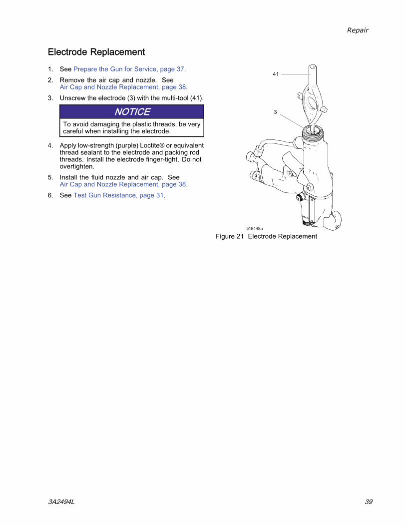
Electrode Replacement
1. See Prepare the Gun for Service, page 37.2. Remove the air cap and nozzle. See
Air Cap and Nozzle Replacement, page 38.3. Unscrew the electrode (3) with the multi-tool (41).
NOTICETo avoid damaging the plastic threads, be verycareful when installing the electrode.
4. Apply low-strength (purple) Loctite® or equivalentthread sealant to the electrode and packing rodthreads. Install the electrode finger-tight. Do notovertighten.
5. Install the fluid nozzle and air cap. SeeAir Cap and Nozzle Replacement, page 38.
6. See Test Gun Resistance, page 31.
Figure 21 Electrode Replacement
3A2494L 39
Repair
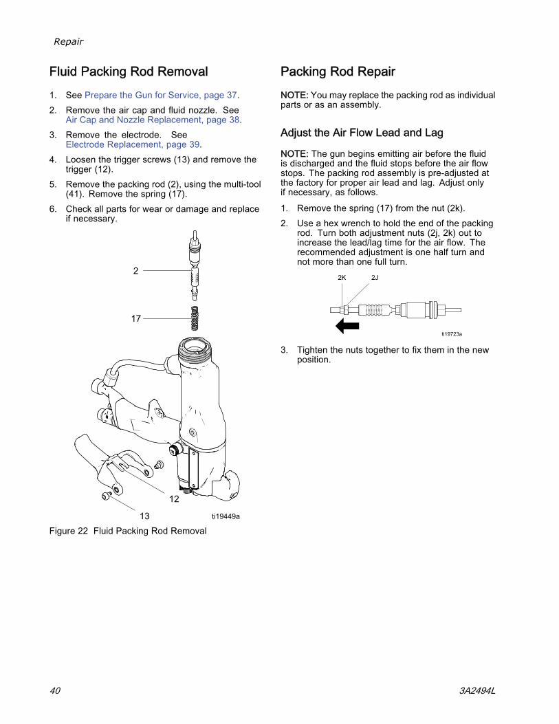
Fluid Packing Rod Removal
1. See Prepare the Gun for Service, page 37.2. Remove the air cap and fluid nozzle. See
Air Cap and Nozzle Replacement, page 38.3. Remove the electrode. See
Electrode Replacement, page 39.4. Loosen the trigger screws (13) and remove the
trigger (12).5. Remove the packing rod (2), using the multi-tool
(41). Remove the spring (17).6. Check all parts for wear or damage and replace
if necessary.
Figure 22 Fluid Packing Rod Removal
Packing Rod Repair
NOTE: You may replace the packing rod as individualparts or as an assembly.
Adjust the Air Flow Lead and Lag
NOTE: The gun begins emitting air before the fluidis discharged and the fluid stops before the air flowstops. The packing rod assembly is pre-adjusted atthe factory for proper air lead and lag. Adjust onlyif necessary, as follows.
1. Remove the spring (17) from the nut (2k).2. Use a hex wrench to hold the end of the packing
rod. Turn both adjustment nuts (2j, 2k) out toincrease the lead/lag time for the air flow. Therecommended adjustment is one half turn andnot more than one full turn.
3. Tighten the nuts together to fix them in the newposition.
40 3A2494L
Repair
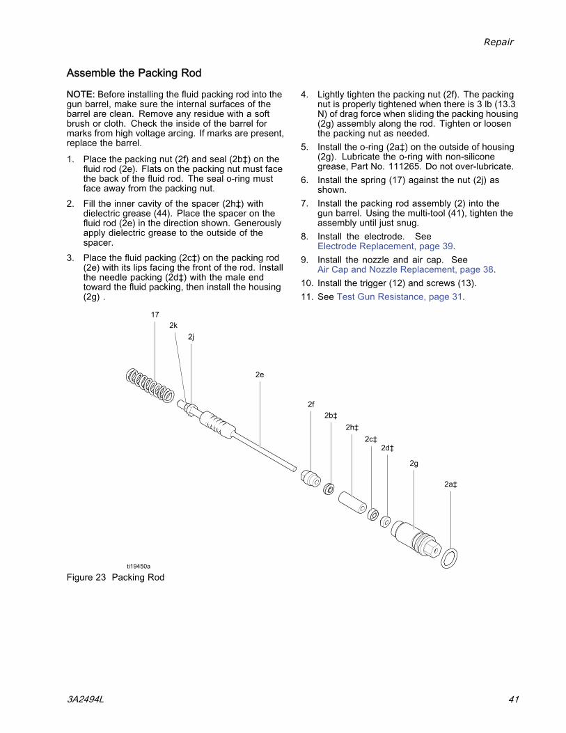
Assemble the Packing Rod
NOTE: Before installing the fluid packing rod into thegun barrel, make sure the internal surfaces of thebarrel are clean. Remove any residue with a softbrush or cloth. Check the inside of the barrel formarks from high voltage arcing. If marks are present,replace the barrel.
1. Place the packing nut (2f) and seal (2b‡) on thefluid rod (2e). Flats on the packing nut must facethe back of the fluid rod. The seal o-ring mustface away from the packing nut.
2. Fill the inner cavity of the spacer (2h‡) withdielectric grease (44). Place the spacer on thefluid rod (2e) in the direction shown. Generouslyapply dielectric grease to the outside of thespacer.
3. Place the fluid packing (2c‡) on the packing rod(2e) with its lips facing the front of the rod. Installthe needle packing (2d‡) with the male endtoward the fluid packing, then install the housing(2g) .
4. Lightly tighten the packing nut (2f). The packingnut is properly tightened when there is 3 lb (13.3N) of drag force when sliding the packing housing(2g) assembly along the rod. Tighten or loosenthe packing nut as needed.
5. Install the o-ring (2a‡) on the outside of housing(2g). Lubricate the o-ring with non-siliconegrease, Part No. 111265. Do not over-lubricate.
6. Install the spring (17) against the nut (2j) asshown.
7. Install the packing rod assembly (2) into thegun barrel. Using the multi-tool (41), tighten theassembly until just snug.
8. Install the electrode. SeeElectrode Replacement, page 39.
9. Install the nozzle and air cap. SeeAir Cap and Nozzle Replacement, page 38.
10. Install the trigger (12) and screws (13).11. See Test Gun Resistance, page 31.
Figure 23 Packing Rod
3A2494L 41
Repair
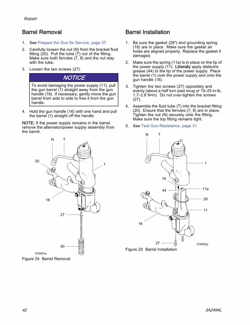
Barrel Removal
1. See Prepare the Gun for Service, page 37.2. Carefully loosen the nut (N) from the bracket fluid
fitting (20). Pull the tube (T) out of the fitting.Make sure both ferrules (7, 8) and the nut staywith the tube.
3. Loosen the two screws (27).
NOTICETo avoid damaging the power supply (11), pullthe gun barrel (1) straight away from the gunhandle (16). If necessary, gently move the gunbarrel from side to side to free it from the gunhandle.
4. Hold the gun handle (16) with one hand and pullthe barrel (1) straight off the handle.
NOTE: If the power supply remains in the barrel,remove the alternator/power supply assembly fromthe barrel.
Figure 24 Barrel Removal
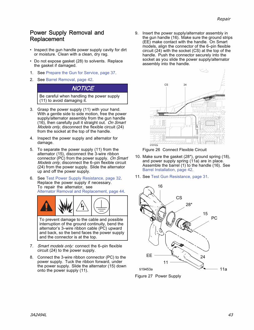
Barrel Installation
1. Be sure the gasket (28*) and grounding spring(18) are in place. Make sure the gasket airholes are aligned properly. Replace the gasket ifdamaged.
2. Make sure the spring (11a) is in place on the tip ofthe power supply (11). Liberally apply dielectricgrease (44) to the tip of the power supply. Placethe barrel (1) over the power supply and onto thegun handle (16).
3. Tighten the two screws (27) oppositely andevenly (about a half turn past snug or 15–25 in-lb,1.7–2.8 N•m). Do not over-tighten the screws(27).
4. Assemble the fluid tube (T) into the bracket fitting(20). Ensure that the ferrules (7, 8) are in place.Tighten the nut (N) securely onto the fitting.Make sure the top fitting remains tight.
5. See Test Gun Resistance, page 31.
Figure 25 Barrel Installation
42 3A2494L
Repair
Power Supply Removal andReplacement
• Inspect the gun handle power supply cavity for dirtor moisture. Clean with a clean, dry rag.
• Do not expose gasket (28) to solvents. Replacethe gasket if damaged.
1. See Prepare the Gun for Service, page 37.2. See Barrel Removal, page 42.
NOTICEBe careful when handling the power supply(11) to avoid damaging it.
3. Grasp the power supply (11) with your hand.With a gentle side to side motion, free the powersupply/alternator assembly from the gun handle(16), then carefully pull it straight out. On SmartModels only, disconnect the flexible circuit (24)from the socket at the top of the handle.
4. Inspect the power supply and alternator fordamage.
5. To separate the power supply (11) from thealternator (15), disconnect the 3-wire ribbonconnector (PC) from the power supply. On SmartModels only, disconnect the 6–pin flexible circuit(24) from the power supply. Slide the alternatorup and off the power supply.
6. See Test Power Supply Resistance, page 32.Replace the power supply if necessary.To repair the alternator, seeAlternator Removal and Replacement, page 44.
To prevent damage to the cable and possibleinterruption of the ground continuity, bend thealternator’s 3–wire ribbon cable (PC) upwardand back, so the bend faces the power supplyand the connector is at the top.
7. Smart models only: connect the 6–pin flexiblecircuit (24) to the power supply.
8. Connect the 3-wire ribbon connector (PC) to thepower supply. Tuck the ribbon forward, underthe power supply. Slide the alternator (15) downonto the power supply (11).
9. Insert the power supply/alternator assembly inthe gun handle (16). Make sure the ground strips(EE) make contact with the handle. On Smartmodels, align the connector of the 6–pin flexiblecircuit (24) with the socket (CS) at the top of thehandle. Push the connector securely into thesocket as you slide the power supply/alternatorassembly into the handle.
Figure 26 Connect Flexible Circuit10. Make sure the gasket (28*), ground spring (18),
and power supply spring (11a) are in place.Assemble the barrel (1) to the handle (16). SeeBarrel Installation, page 42.
11. See Test Gun Resistance, page 31.
Figure 27 Power Supply
3A2494L 43
Repair
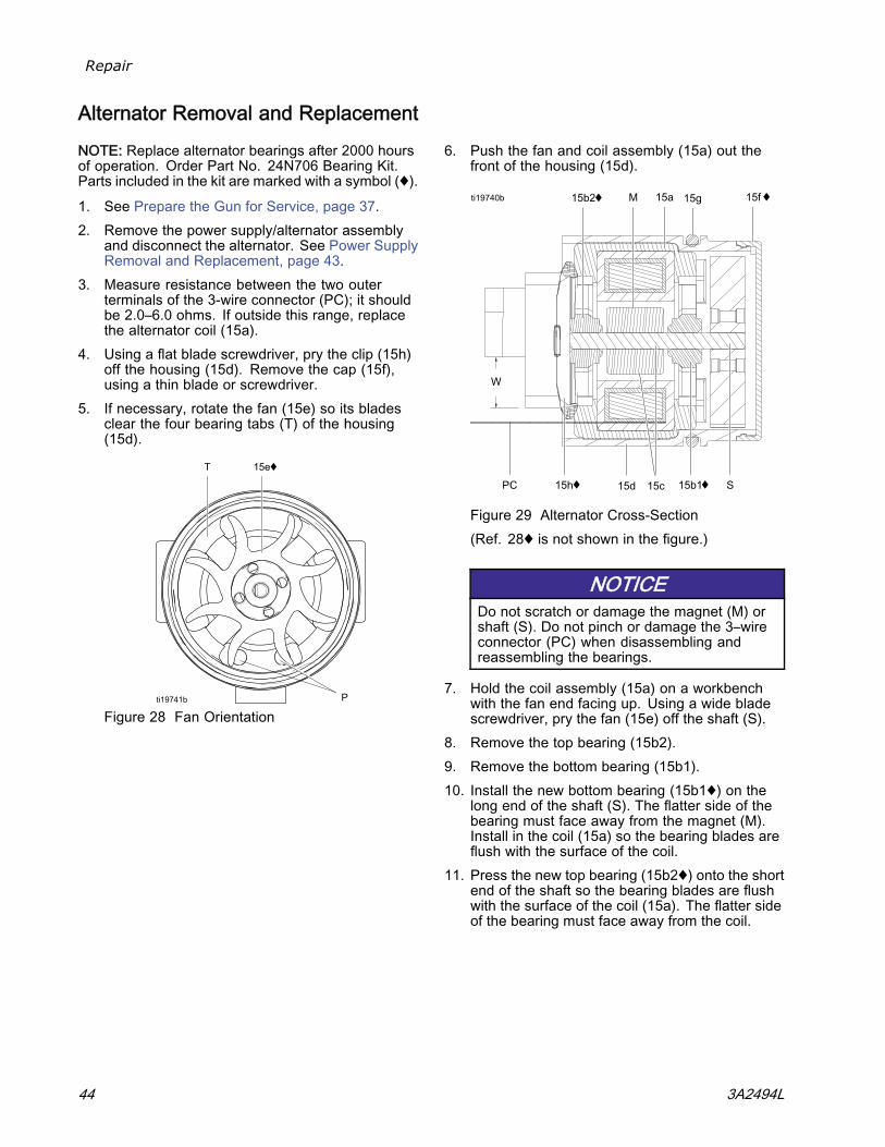
Alternator Removal and Replacement
NOTE: Replace alternator bearings after 2000 hoursof operation. Order Part No. 24N706 Bearing Kit.Parts included in the kit are marked with a symbol (♦).
1. See Prepare the Gun for Service, page 37.2. Remove the power supply/alternator assembly
and disconnect the alternator. See Power SupplyRemoval and Replacement, page 43.
3. Measure resistance between the two outerterminals of the 3-wire connector (PC); it shouldbe 2.0–6.0 ohms. If outside this range, replacethe alternator coil (15a).
4. Using a flat blade screwdriver, pry the clip (15h)off the housing (15d). Remove the cap (15f),using a thin blade or screwdriver.
5. If necessary, rotate the fan (15e) so its bladesclear the four bearing tabs (T) of the housing(15d).
Figure 28 Fan Orientation
6. Push the fan and coil assembly (15a) out thefront of the housing (15d).
Figure 29 Alternator Cross-Section(Ref. 28♦ is not shown in the figure.)
NOTICEDo not scratch or damage the magnet (M) orshaft (S). Do not pinch or damage the 3–wireconnector (PC) when disassembling andreassembling the bearings.
7. Hold the coil assembly (15a) on a workbenchwith the fan end facing up. Using a wide bladescrewdriver, pry the fan (15e) off the shaft (S).
8. Remove the top bearing (15b2).9. Remove the bottom bearing (15b1).10. Install the new bottom bearing (15b1♦) on the
long end of the shaft (S). The flatter side of thebearing must face away from the magnet (M).Install in the coil (15a) so the bearing blades areflush with the surface of the coil.
11. Press the new top bearing (15b2♦) onto the shortend of the shaft so the bearing blades are flushwith the surface of the coil (15a). The flatter sideof the bearing must face away from the coil.
44 3A2494L
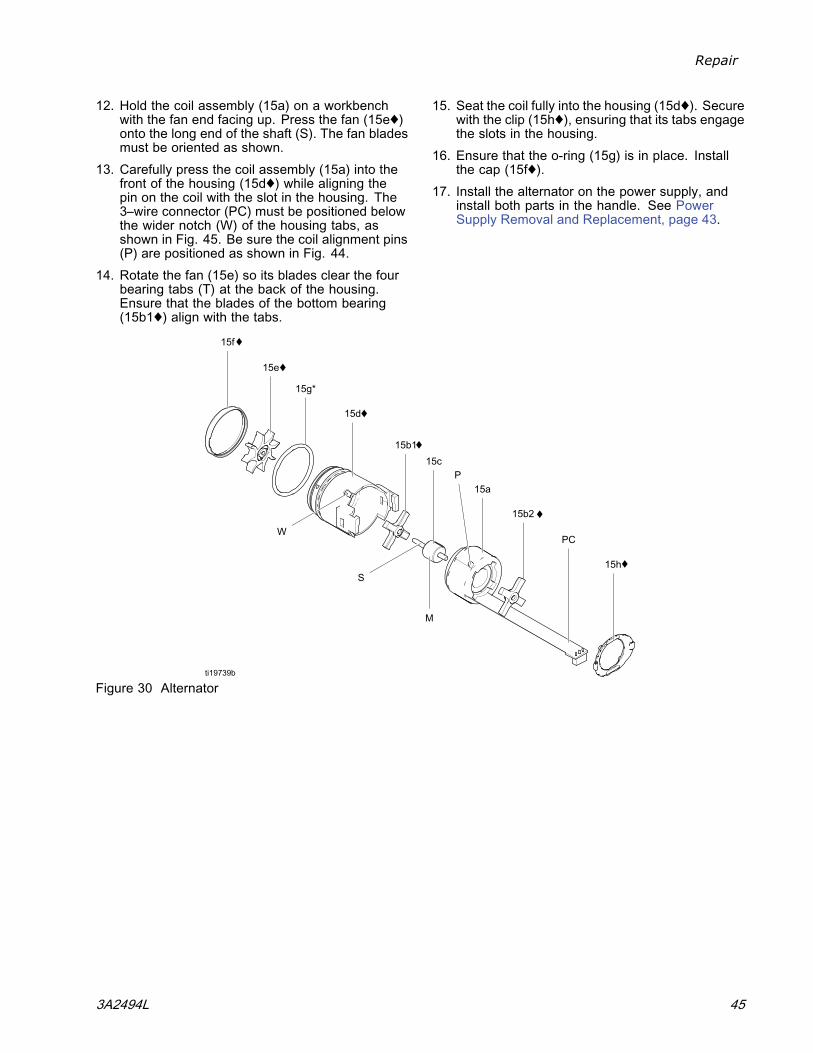
Repair
12. Hold the coil assembly (15a) on a workbenchwith the fan end facing up. Press the fan (15e♦)onto the long end of the shaft (S). The fan bladesmust be oriented as shown.
13. Carefully press the coil assembly (15a) into thefront of the housing (15d♦) while aligning thepin on the coil with the slot in the housing. The3–wire connector (PC) must be positioned belowthe wider notch (W) of the housing tabs, asshown in Fig. 45. Be sure the coil alignment pins(P) are positioned as shown in Fig. 44.
14. Rotate the fan (15e) so its blades clear the fourbearing tabs (T) at the back of the housing.Ensure that the blades of the bottom bearing(15b1♦) align with the tabs.
15. Seat the coil fully into the housing (15d♦). Securewith the clip (15h♦), ensuring that its tabs engagethe slots in the housing.
16. Ensure that the o-ring (15g) is in place. Installthe cap (15f♦).
17. Install the alternator on the power supply, andinstall both parts in the handle. See PowerSupply Removal and Replacement, page 43.
Figure 30 Alternator
3A2494L 45
Repair
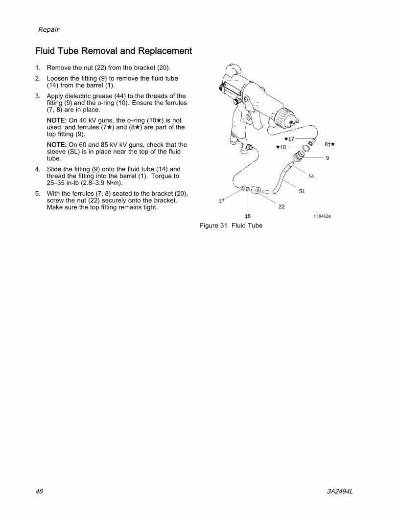
Fluid Tube Removal and Replacement
1. Remove the nut (22) from the bracket (20).2. Loosen the fitting (9) to remove the fluid tube
(14) from the barrel (1).3. Apply dielectric grease (44) to the threads of the
fitting (9) and the o-ring (10). Ensure the ferrules(7, 8) are in place.NOTE: On 40 kV guns, the o–ring (10★) is notused, and ferrules (7★) and (8★) are part of thetop fitting (9).NOTE: On 60 and 85 kV kV guns, check that thesleeve (SL) is in place near the top of the fluidtube.
4. Slide the fitting (9) onto the fluid tube (14) andthread the fitting into the barrel (1). Torque to25–35 in-lb (2.8–3.9 N•m).
5. With the ferrules (7, 8) seated to the bracket (20),screw the nut (22) securely onto the bracket.Make sure the top fitting remains tight.
Figure 31 Fluid Tube
46 3A2494L
Repair
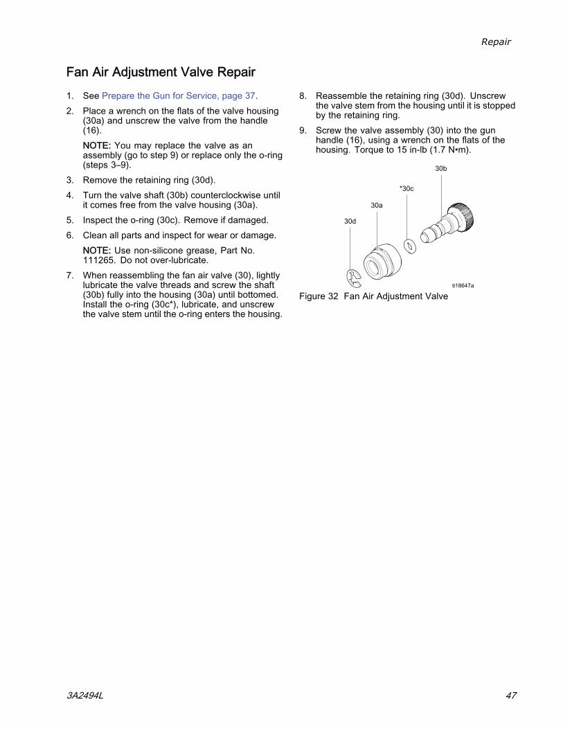
Fan Air Adjustment Valve Repair
1. See Prepare the Gun for Service, page 37.2. Place a wrench on the flats of the valve housing
(30a) and unscrew the valve from the handle(16).NOTE: You may replace the valve as anassembly (go to step 9) or replace only the o-ring(steps 3–9).
3. Remove the retaining ring (30d).4. Turn the valve shaft (30b) counterclockwise until
it comes free from the valve housing (30a).5. Inspect the o-ring (30c). Remove if damaged.6. Clean all parts and inspect for wear or damage.
NOTE: Use non-silicone grease, Part No.111265. Do not over-lubricate.
7. When reassembling the fan air valve (30), lightlylubricate the valve threads and screw the shaft(30b) fully into the housing (30a) until bottomed.Install the o-ring (30c*), lubricate, and unscrewthe valve stem until the o-ring enters the housing.
8. Reassemble the retaining ring (30d). Unscrewthe valve stem from the housing until it is stoppedby the retaining ring.
9. Screw the valve assembly (30) into the gunhandle (16), using a wrench on the flats of thehousing. Torque to 15 in-lb (1.7 N•m).
Figure 32 Fan Air Adjustment Valve
3A2494L 47
Repair
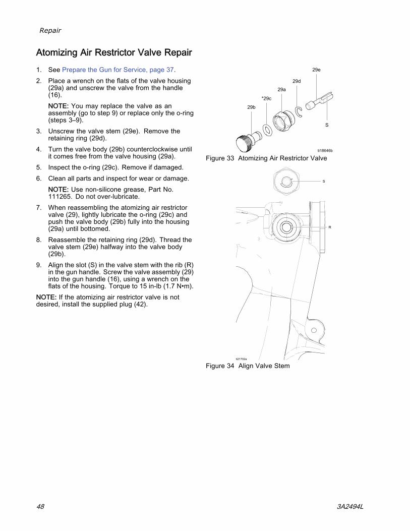
Atomizing Air Restrictor Valve Repair
1. See Prepare the Gun for Service, page 37.2. Place a wrench on the flats of the valve housing
(29a) and unscrew the valve from the handle(16).NOTE: You may replace the valve as anassembly (go to step 9) or replace only the o-ring(steps 3–9).
3. Unscrew the valve stem (29e). Remove theretaining ring (29d).
4. Turn the valve body (29b) counterclockwise untilit comes free from the valve housing (29a).
5. Inspect the o-ring (29c). Remove if damaged.6. Clean all parts and inspect for wear or damage.
NOTE: Use non-silicone grease, Part No.111265. Do not over-lubricate.
7. When reassembling the atomizing air restrictorvalve (29), lightly lubricate the o-ring (29c) andpush the valve body (29b) fully into the housing(29a) until bottomed.
8. Reassemble the retaining ring (29d). Thread thevalve stem (29e) halfway into the valve body(29b).
9. Align the slot (S) in the valve stem with the rib (R)in the gun handle. Screw the valve assembly (29)into the gun handle (16), using a wrench on theflats of the housing. Torque to 15 in-lb (1.7 N•m).
NOTE: If the atomizing air restrictor valve is notdesired, install the supplied plug (42).
Figure 33 Atomizing Air Restrictor Valve
Figure 34 Align Valve Stem
48 3A2494L
Repair
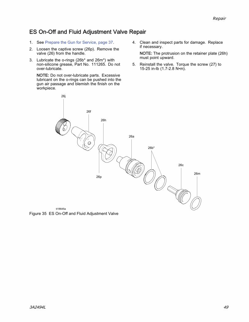
ES On-Off and Fluid Adjustment Valve Repair
1. See Prepare the Gun for Service, page 37.2. Loosen the captive screw (26p). Remove the
valve (26) from the handle.3. Lubricate the o-rings (26b* and 26m*) with
non-silicone grease, Part No. 111265. Do notover-lubricate.NOTE: Do not over-lubricate parts. Excessivelubricant on the o-rings can be pushed into thegun air passage and blemish the finish on theworkpiece.
4. Clean and inspect parts for damage. Replaceif necessary.NOTE: The protrusion on the retainer plate (26h)must point upward.
5. Reinstall the valve. Torque the screw (27) to15-25 in-lb (1.7-2.8 N•m).
Figure 35 ES On-Off and Fluid Adjustment Valve
3A2494L 49
Repair
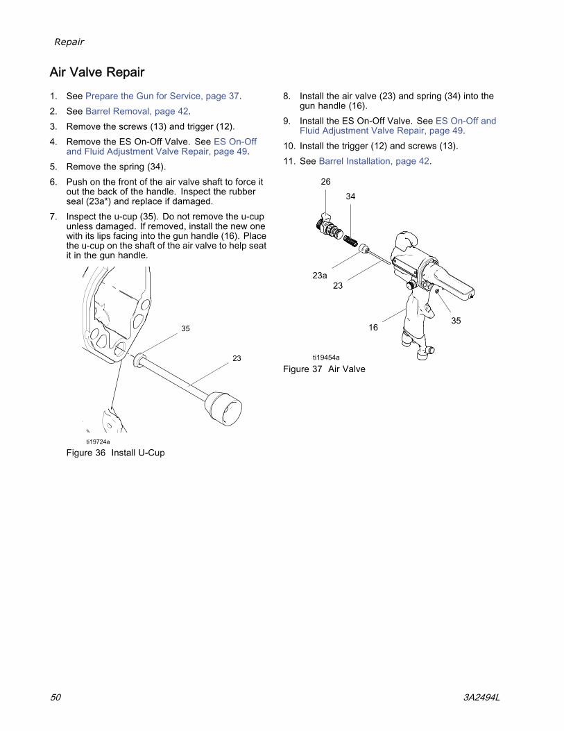
Air Valve Repair
1. See Prepare the Gun for Service, page 37.2. See Barrel Removal, page 42.3. Remove the screws (13) and trigger (12).4. Remove the ES On-Off Valve. See ES On-Off
and Fluid Adjustment Valve Repair, page 49.5. Remove the spring (34).6. Push on the front of the air valve shaft to force it
out the back of the handle. Inspect the rubberseal (23a*) and replace if damaged.
7. Inspect the u-cup (35). Do not remove the u-cupunless damaged. If removed, install the new onewith its lips facing into the gun handle (16). Placethe u-cup on the shaft of the air valve to help seatit in the gun handle.
Figure 36 Install U-Cup
8. Install the air valve (23) and spring (34) into thegun handle (16).
9. Install the ES On-Off Valve. See ES On-Off andFluid Adjustment Valve Repair, page 49.
10. Install the trigger (12) and screws (13).11. See Barrel Installation, page 42.
Figure 37 Air Valve
50 3A2494L
Repair
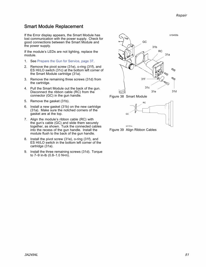
Smart Module Replacement
If the Error display appears, the Smart Module haslost communication with the power supply. Check forgood connections between the Smart Module andthe power supply.
If the module’s LEDs are not lighting, replace themodule.
1. See Prepare the Gun for Service, page 37.2. Remove the pivot screw (31e), o-ring (31f), and
ES HI/LO switch (31c) at the bottom left corner ofthe Smart Module cartridge (31a).
3. Remove the remaining three screws (31d) fromthe cartridge.
4. Pull the Smart Module out the back of the gun.Disconnect the ribbon cable (RC) from theconnector (GC) in the gun handle.
5. Remove the gasket (31b).6. Install a new gasket (31b) on the new cartridge
(31a). Make sure the notched corners of thegasket are at the top.
7. Align the module’s ribbon cable (RC) withthe gun’s cable (GC) and slide them securelytogether, as shown. Tuck the connected cablesinto the recess of the gun handle. Install themodule flush to the back of the gun handle.
8. Install the pivot screw (31e), o-ring (31f), andES HI/LO switch in the bottom left corner of thecartridge (31a).
9. Install the three remaining screws (31d). Torqueto 7–9 in-lb (0.8–1.0 N•m).
Figure 38 Smart Module
Figure 39 Align Ribbon Cables
3A2494L 51
Repair
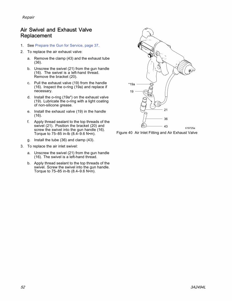
Air Swivel and Exhaust ValveReplacement
1. See Prepare the Gun for Service, page 37.2. To replace the air exhaust valve:
a. Remove the clamp (43) and the exhaust tube(36).
b. Unscrew the swivel (21) from the gun handle(16). The swivel is a left-hand thread.Remove the bracket (20).
c. Pull the exhaust valve (19) from the handle(16). Inspect the o-ring (19a) and replace ifnecessary.
d. Install the o-ring (19a*) on the exhaust valve(19). Lubricate the o-ring with a light coatingof non-silicone grease.
e. Install the exhaust valve (19) in the handle(16).
f. Apply thread sealant to the top threads of theswivel (21). Position the bracket (20) andscrew the swivel into the gun handle (16).Torque to 75–85 in-lb (8.4–9.6 N•m).
g. Install the tube (36) and clamp (43).3. To replace the air inlet swivel:
a. Unscrew the swivel (21) from the gun handle(16). The swivel is a left-hand thread.
b. Apply thread sealant to the top threads of theswivel. Screw the swivel into the gun handle.Torque to 75–85 in-lb (8.4–9.6 N•m).
Figure 40 Air Inlet Fitting and Air Exhaust Valve
52 3A2494L
Parts
Parts
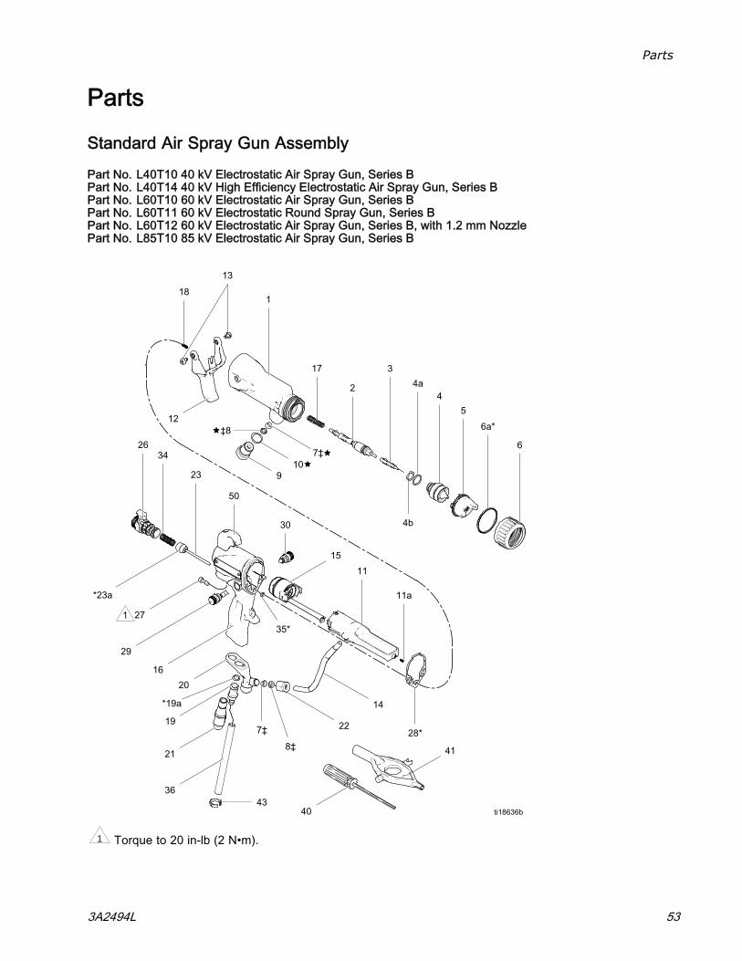
Standard Air Spray Gun Assembly
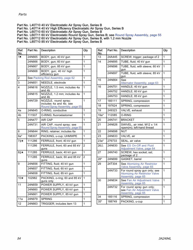
Part No. L40T10 40 kV Electrostatic Air Spray Gun, Series BPart No. L40T14 40 kV High Efficiency Electrostatic Air Spray Gun, Series BPart No. L60T10 60 kV Electrostatic Air Spray Gun, Series BPart No. L60T11 60 kV Electrostatic Round Spray Gun, Series BPart No. L60T12 60 kV Electrostatic Air Spray Gun, Series B, with 1.2 mm NozzlePart No. L85T10 85 kV Electrostatic Air Spray Gun, Series B
1 Torque to 20 in-lb (2 N•m).
3A2494L 53
Parts
Part No. L40T10 40 kV Electrostatic Air Spray Gun, Series BPart No. L40T14 40 kV High Efficiency Electrostatic Air Spray Gun, Series BPart No. L60T10 60 kV Electrostatic Air Spray Gun, Series BPart No. L60T11 60 kV Electrostatic Round Spray Gun, Series B; see Round Spray Assembly, page 55Part No. L60T12 60 kV Electrostatic Air Spray Gun, Series B, with 1.2 mm NozzlePart No. L85T10 85 kV Electrostatic Air Spray Gun, Series B
Ref.No.
Part No. Description Qty
24N665 BODY, gun; 40 kV gun 124N666 BODY, gun; 60 kV gun 124N667 BODY, gun; 85 kV gun 1
1■
24N668 BODY, gun; 40 kV highefficiency gun
1
2 See Packing Rod Assembly, page 62 13 24N651 NEEDLE, electrode 1
24N616 NOZZLE, 1.5 mm; includes 4aand 4b
1
24N615 NOZZLE, 1.2 mm; includes 4aand 4b
1
4
24N729 NOZZLE, round spray;includes 4a and 4b; seeRound Spray Assembly, page 55
1
4a 24N645 O-RING, conductive 14b 111507 O-RING; fluoroelastomer 1
24N477 AIR CAP 1524N731 AIR CAP, round spray; see
Round Spray Assembly, page 551
6 24N644 RING, retainer; includes 6a 16a* 198307 PACKING, u-cup; UHMWPE 1
111286 FERRULE, front; 40 kV gun 17‡★111286 FERRULE, front; 60 and 85 kV
guns2
111285 FERRULE, back; 40 kV gun 18‡★111285 FERRULE, back; 60 and 85 kV
guns2
24N656 FITTING, fluid; 40 kV gun 124N657 FITTING, fluid; 60 kV gun 1
9
24N658 FITTING, fluid; 85 kV gun 110★ 102982 PACKING, o-ring; 60 and 85 kV
guns only1
24N659 POWER SUPPLY, 40 kV gun 124N660 POWER SUPPLY, 60 kV gun 1
11
24N661 POWER SUPPLY, 85 kV gun 111a 24N979 SPRING 112 24N663 TRIGGER; includes item 13 1
Ref.No.
Part No. Description Qty
13 24A445 SCREW, trigger; package of 2 124N695 TUBE, fluid; 40 kV gun 124N696 TUBE, fluid, with sleeve; 60 kV
gun1
14
24N697 TUBE, fluid, with sleeve; 85 kVgun
1
15 24N664 SeeAlternator Assembly, page 63
1
24N751 HANDLE; 40 kV gun 124N752 HANDLE; 60 kV gun 1
16
24N753 HANDLE; 85 kV gun 117 185111 SPRING, compression 118 197624 SPRING, compression 119 249323 VALVE, exhaust 119a* 112085 O-RING 120 24N741 BRACKET 121 24N626 SWIVEL, air inlet; M12 x 1/4
npsm(m); left-hand thread1
22 24N698 NUT 123 24N633 VALVE, air 123a* 276733 SEAL, air valve 126⁂ 24N630 See ES On-Off and Fluid
Adjustment Valve, page 641
27 24N740 SCREW, hex socket; sst;package of 2
1
28* 24N699 GASKET, barrel 124T304 See Atomizing Air Restrictor
Valve Assembly, page 65129
24N733 For round spray gun only; seeAtomizing Air Restrictor ValveAssembly, page 65
1
24N634 See Fan Air Adjustment ValveAssembly, page 65
130
24N732 For round spray gun only;see Fan Air Adjustment ValveAssembly, page 65
1
34 185116 SPRING, compression 135* 188749 PACKING, u-cup 1
54 3A2494L
Parts
Ref.No.
Part No. Description Qty
36 185103 TUBE, exhaust; 1/4 in. (6 mm)ID (shipped loose)
1
40 107460 TOOL, wrench, ball end; 4 mm(shipped loose)
1
41 276741 MULTI-TOOL (shipped loose) 142 24N786 PLUG, restrictor (shipped loose;
for use instead of item 29)1
43 110231 CLAMP, exhaust tube (shippedloose)
1
44 116553 GREASE, dielectric; 1 oz (30ml) tube (not shown)
1
45 117824 GLOVE, conductive, medium;package of 12; also availablein small (117823) and large(117825)
1
Ref.No.
Part No. Description Qty
24N603 COVER, gun, 40 and 60 kVguns; package of 10
146
24N604 COVER, gun, 85 kV guns;package of 10
1
47▲ 179791 TAG, warning (not shown) 148▲ 16P802 SIGN, warning (not shown) 149 24N730 DIFFUSER, for round
spray gun only; seeRound Spray Assembly, page 55
1
50 24N783 HOOK; includes screw 1
▲ Replacement Danger and Warning labels, tags,and cards are available at no cost.
* These parts are included in Air Seal Repair Kit24N789 (purchase separately).
‡ These parts are included in Fluid Seal Repair Kit24N790 (purchase separately).
■ Gun bodies (Ref. 1) include the barrel gasket (Ref.28).
⁂ EX On/Off Valve Restrictor Kit 26A160 is availablefor customers with high atomization air pressureapplications. Use this accessory if the turbine lightindicator is red and you want to maintain a higherapplication air pressure. Install the kit, then adjustthe pressure as needed to ensure operation in thegreen light.
NOTE: On 40 kV guns, the o–ring (10★) is not used,and ferrules (7★) and (8★) are part of the top fitting(9).
Round Spray Assembly
3A2494L 55
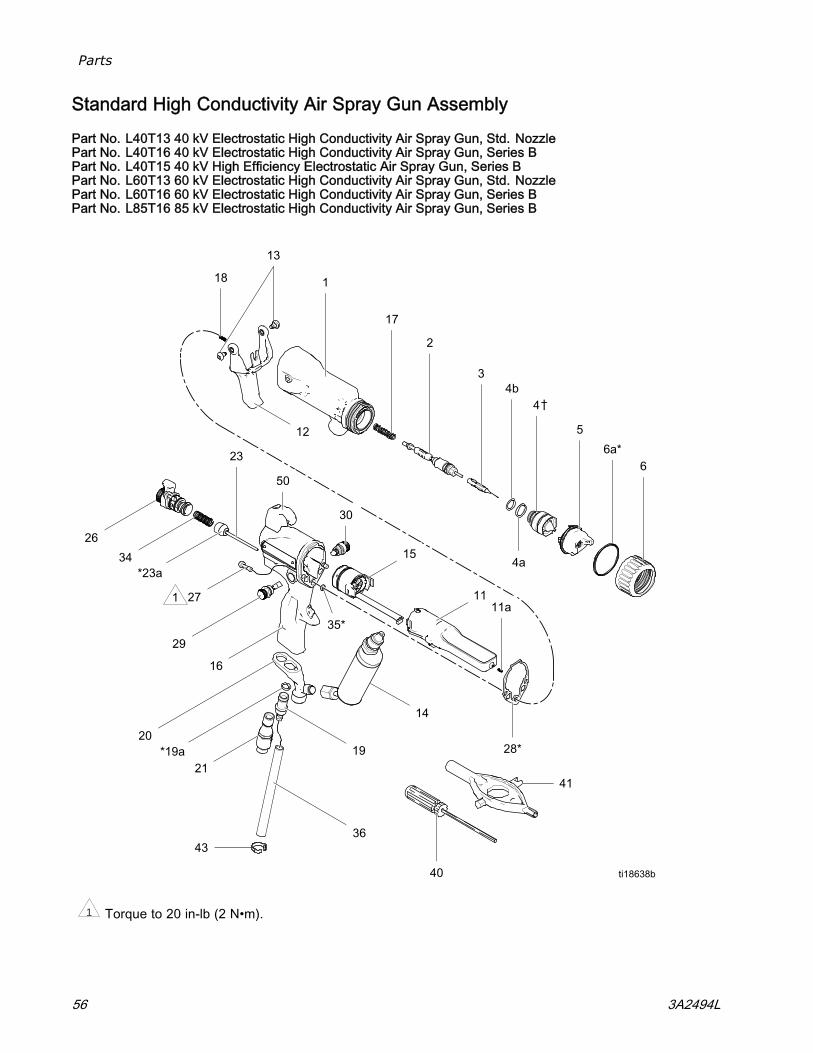
Parts
Standard High Conductivity Air Spray Gun Assembly
Part No. L40T13 40 kV Electrostatic High Conductivity Air Spray Gun, Std. NozzlePart No. L40T16 40 kV Electrostatic High Conductivity Air Spray Gun, Series BPart No. L40T15 40 kV High Efficiency Electrostatic Air Spray Gun, Series BPart No. L60T13 60 kV Electrostatic High Conductivity Air Spray Gun, Std. NozzlePart No. L60T16 60 kV Electrostatic High Conductivity Air Spray Gun, Series BPart No. L85T16 85 kV Electrostatic High Conductivity Air Spray Gun, Series B
1 Torque to 20 in-lb (2 N•m).
56 3A2494L
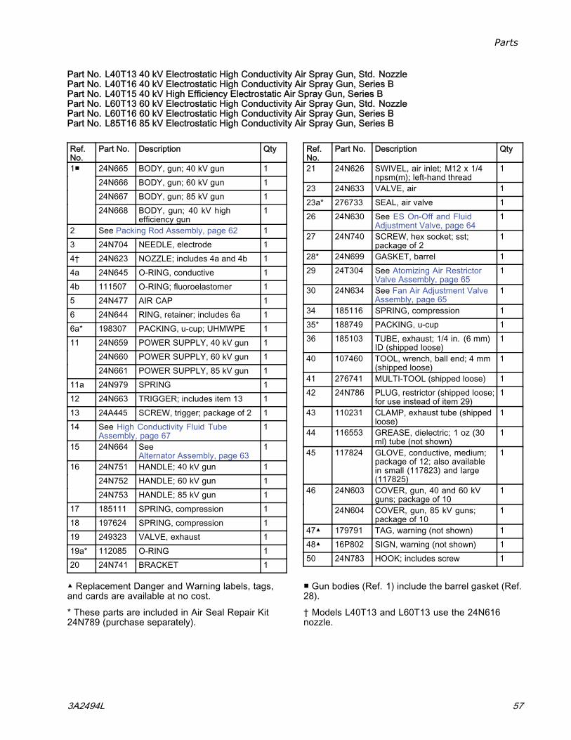
Parts
Part No. L40T13 40 kV Electrostatic High Conductivity Air Spray Gun, Std. NozzlePart No. L40T16 40 kV Electrostatic High Conductivity Air Spray Gun, Series BPart No. L40T15 40 kV High Efficiency Electrostatic Air Spray Gun, Series BPart No. L60T13 60 kV Electrostatic High Conductivity Air Spray Gun, Std. NozzlePart No. L60T16 60 kV Electrostatic High Conductivity Air Spray Gun, Series BPart No. L85T16 85 kV Electrostatic High Conductivity Air Spray Gun, Series B
Ref.No.
Part No. Description Qty
24N665 BODY, gun; 40 kV gun 124N666 BODY, gun; 60 kV gun 124N667 BODY, gun; 85 kV gun 1
1■
24N668 BODY, gun; 40 kV highefficiency gun
1
2 See Packing Rod Assembly, page 62 13 24N704 NEEDLE, electrode 14† 24N623 NOZZLE; includes 4a and 4b 14a 24N645 O-RING, conductive 14b 111507 O-RING; fluoroelastomer 15 24N477 AIR CAP 16 24N644 RING, retainer; includes 6a 16a* 198307 PACKING, u-cup; UHMWPE 1
24N659 POWER SUPPLY, 40 kV gun 124N660 POWER SUPPLY, 60 kV gun 1
11
24N661 POWER SUPPLY, 85 kV gun 111a 24N979 SPRING 112 24N663 TRIGGER; includes item 13 113 24A445 SCREW, trigger; package of 2 114 See High Conductivity Fluid Tube
Assembly, page 671
15 24N664 SeeAlternator Assembly, page 63
1
24N751 HANDLE; 40 kV gun 124N752 HANDLE; 60 kV gun 1
16
24N753 HANDLE; 85 kV gun 117 185111 SPRING, compression 118 197624 SPRING, compression 119 249323 VALVE, exhaust 119a* 112085 O-RING 120 24N741 BRACKET 1
Ref.No.
Part No. Description Qty
21 24N626 SWIVEL, air inlet; M12 x 1/4npsm(m); left-hand thread
1
23 24N633 VALVE, air 123a* 276733 SEAL, air valve 126 24N630 See ES On-Off and Fluid
Adjustment Valve, page 641
27 24N740 SCREW, hex socket; sst;package of 2
1
28* 24N699 GASKET, barrel 129 24T304 See Atomizing Air Restrictor
Valve Assembly, page 651
30 24N634 See Fan Air Adjustment ValveAssembly, page 65
1
34 185116 SPRING, compression 135* 188749 PACKING, u-cup 136 185103 TUBE, exhaust; 1/4 in. (6 mm)
ID (shipped loose)1
40 107460 TOOL, wrench, ball end; 4 mm(shipped loose)
1
41 276741 MULTI-TOOL (shipped loose) 142 24N786 PLUG, restrictor (shipped loose;
for use instead of item 29)1
43 110231 CLAMP, exhaust tube (shippedloose)
1
44 116553 GREASE, dielectric; 1 oz (30ml) tube (not shown)
1
45 117824 GLOVE, conductive, medium;package of 12; also availablein small (117823) and large(117825)
1
24N603 COVER, gun, 40 and 60 kVguns; package of 10
146
24N604 COVER, gun, 85 kV guns;package of 10
1
47▲ 179791 TAG, warning (not shown) 148▲ 16P802 SIGN, warning (not shown) 150 24N783 HOOK; includes screw 1
▲ Replacement Danger and Warning labels, tags,and cards are available at no cost.
* These parts are included in Air Seal Repair Kit24N789 (purchase separately).
■ Gun bodies (Ref. 1) include the barrel gasket (Ref.28).
† Models L40T13 and L60T13 use the 24N616nozzle.
3A2494L 57
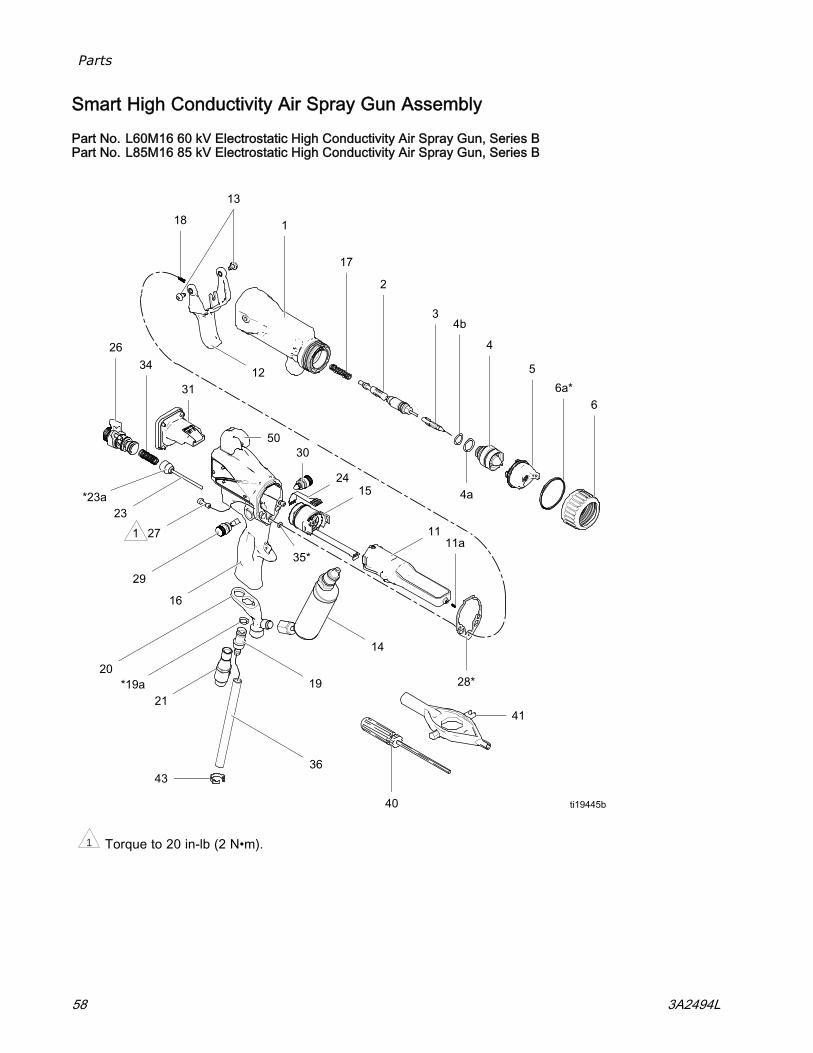
Parts
Smart High Conductivity Air Spray Gun Assembly
Part No. L60M16 60 kV Electrostatic High Conductivity Air Spray Gun, Series BPart No. L85M16 85 kV Electrostatic High Conductivity Air Spray Gun, Series B
1 Torque to 20 in-lb (2 N•m).
58 3A2494L
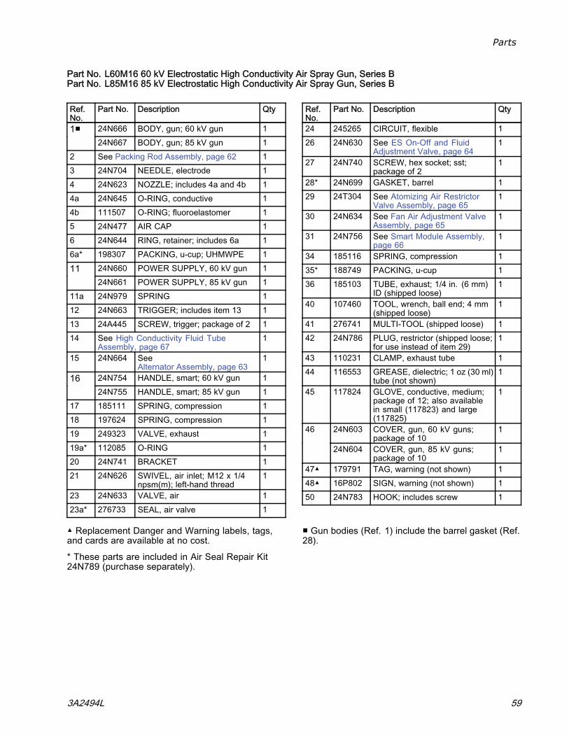
Parts
Part No. L60M16 60 kV Electrostatic High Conductivity Air Spray Gun, Series BPart No. L85M16 85 kV Electrostatic High Conductivity Air Spray Gun, Series B
Ref.No.
Part No. Description Qty
24N666 BODY, gun; 60 kV gun 11■24N667 BODY, gun; 85 kV gun 1
2 See Packing Rod Assembly, page 62 13 24N704 NEEDLE, electrode 14 24N623 NOZZLE; includes 4a and 4b 14a 24N645 O-RING, conductive 14b 111507 O-RING; fluoroelastomer 15 24N477 AIR CAP 16 24N644 RING, retainer; includes 6a 16a* 198307 PACKING, u-cup; UHMWPE 1
24N660 POWER SUPPLY, 60 kV gun 11124N661 POWER SUPPLY, 85 kV gun 1
11a 24N979 SPRING 112 24N663 TRIGGER; includes item 13 113 24A445 SCREW, trigger; package of 2 114 See High Conductivity Fluid Tube
Assembly, page 671
15 24N664 SeeAlternator Assembly, page 63
1
24N754 HANDLE, smart; 60 kV gun 11624N755 HANDLE, smart; 85 kV gun 1
17 185111 SPRING, compression 118 197624 SPRING, compression 119 249323 VALVE, exhaust 119a* 112085 O-RING 120 24N741 BRACKET 121 24N626 SWIVEL, air inlet; M12 x 1/4
npsm(m); left-hand thread1
23 24N633 VALVE, air 123a* 276733 SEAL, air valve 1
Ref.No.
Part No. Description Qty
24 245265 CIRCUIT, flexible 126 24N630 See ES On-Off and Fluid
Adjustment Valve, page 641
27 24N740 SCREW, hex socket; sst;package of 2
1
28* 24N699 GASKET, barrel 129 24T304 See Atomizing Air Restrictor
Valve Assembly, page 651
30 24N634 See Fan Air Adjustment ValveAssembly, page 65
1
31 24N756 See Smart Module Assembly,page 66
1
34 185116 SPRING, compression 135* 188749 PACKING, u-cup 136 185103 TUBE, exhaust; 1/4 in. (6 mm)
ID (shipped loose)1
40 107460 TOOL, wrench, ball end; 4 mm(shipped loose)
1
41 276741 MULTI-TOOL (shipped loose) 142 24N786 PLUG, restrictor (shipped loose;
for use instead of item 29)1
43 110231 CLAMP, exhaust tube 144 116553 GREASE, dielectric; 1 oz (30 ml)
tube (not shown)1
45 117824 GLOVE, conductive, medium;package of 12; also availablein small (117823) and large(117825)
1
24N603 COVER, gun, 60 kV guns;package of 10
146
24N604 COVER, gun, 85 kV guns;package of 10
1
47▲ 179791 TAG, warning (not shown) 148▲ 16P802 SIGN, warning (not shown) 150 24N783 HOOK; includes screw 1
▲ Replacement Danger and Warning labels, tags,and cards are available at no cost.
* These parts are included in Air Seal Repair Kit24N789 (purchase separately).
■ Gun bodies (Ref. 1) include the barrel gasket (Ref.28).
3A2494L 59
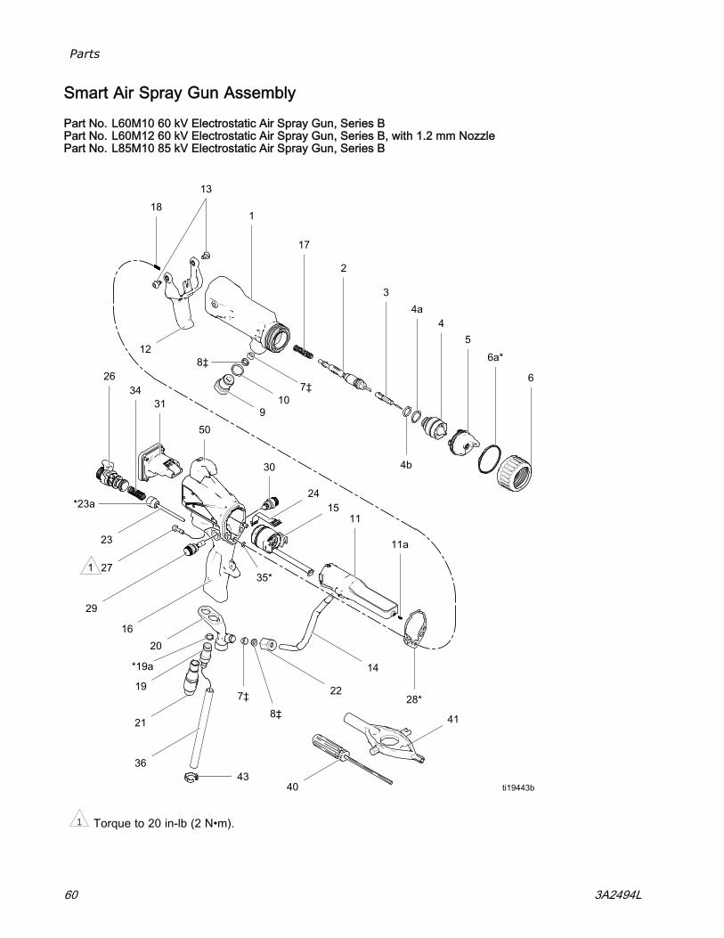
Parts
Smart Air Spray Gun Assembly
Part No. L60M10 60 kV Electrostatic Air Spray Gun, Series BPart No. L60M12 60 kV Electrostatic Air Spray Gun, Series B, with 1.2 mm NozzlePart No. L85M10 85 kV Electrostatic Air Spray Gun, Series B
1 Torque to 20 in-lb (2 N•m).
60 3A2494L
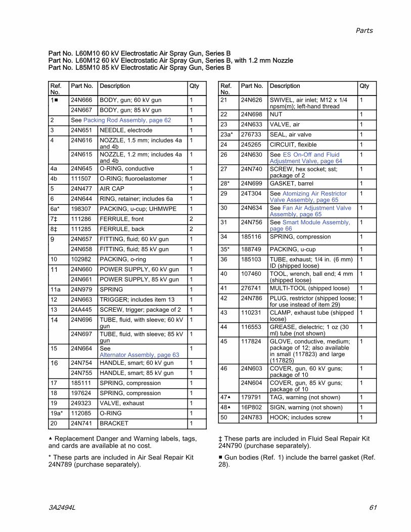
Parts
Part No. L60M10 60 kV Electrostatic Air Spray Gun, Series BPart No. L60M12 60 kV Electrostatic Air Spray Gun, Series B, with 1.2 mm NozzlePart No. L85M10 85 kV Electrostatic Air Spray Gun, Series B
Ref.No.
Part No. Description Qty
24N666 BODY, gun; 60 kV gun 11■24N667 BODY, gun; 85 kV gun 1
2 See Packing Rod Assembly, page 62 13 24N651 NEEDLE, electrode 1
24N616 NOZZLE, 1.5 mm; includes 4aand 4b
14
24N615 NOZZLE, 1.2 mm; includes 4aand 4b
1
4a 24N645 O-RING, conductive 14b 111507 O-RING; fluoroelastomer 15 24N477 AIR CAP 16 24N644 RING, retainer; includes 6a 16a* 198307 PACKING, u-cup; UHMWPE 17‡ 111286 FERRULE, front 28‡ 111285 FERRULE, back 2
24N657 FITTING, fluid; 60 kV gun 1924N658 FITTING, fluid; 85 kV gun 1
10 102982 PACKING, o-ring 124N660 POWER SUPPLY, 60 kV gun 11124N661 POWER SUPPLY, 85 kV gun 1
11a 24N979 SPRING 112 24N663 TRIGGER; includes item 13 113 24A445 SCREW, trigger; package of 2 1
24N696 TUBE, fluid, with sleeve; 60 kVgun
114
24N697 TUBE, fluid, with sleeve; 85 kVgun
1
15 24N664 SeeAlternator Assembly, page 63
1
24N754 HANDLE, smart; 60 kV gun 11624N755 HANDLE, smart; 85 kV gun 1
17 185111 SPRING, compression 118 197624 SPRING, compression 119 249323 VALVE, exhaust 119a* 112085 O-RING 120 24N741 BRACKET 1
Ref.No.
Part No. Description Qty
21 24N626 SWIVEL, air inlet; M12 x 1/4npsm(m); left-hand thread
1
22 24N698 NUT 123 24N633 VALVE, air 123a* 276733 SEAL, air valve 124 245265 CIRCUIT, flexible 126 24N630 See ES On-Off and Fluid
Adjustment Valve, page 641
27 24N740 SCREW, hex socket; sst;package of 2
1
28* 24N699 GASKET, barrel 129 24T304 See Atomizing Air Restrictor
Valve Assembly, page 651
30 24N634 See Fan Air Adjustment ValveAssembly, page 65
1
31 24N756 See Smart Module Assembly,page 66
1
34 185116 SPRING, compression 1
35* 188749 PACKING, u-cup 136 185103 TUBE, exhaust; 1/4 in. (6 mm)
ID (shipped loose)1
40 107460 TOOL, wrench, ball end; 4 mm(shipped loose)
1
41 276741 MULTI-TOOL (shipped loose) 142 24N786 PLUG, restrictor (shipped loose;
for use instead of item 29)1
43 110231 CLAMP, exhaust tube (shippedloose)
1
44 116553 GREASE, dielectric; 1 oz (30ml) tube (not shown)
1
45 117824 GLOVE, conductive, medium;package of 12; also availablein small (117823) and large(117825)
1
24N603 COVER, gun, 60 kV guns;package of 10
146
24N604 COVER, gun, 85 kV guns;package of 10
1
47▲ 179791 TAG, warning (not shown) 148▲ 16P802 SIGN, warning (not shown) 150 24N783 HOOK; includes screw 1
▲ Replacement Danger and Warning labels, tags,and cards are available at no cost.
* These parts are included in Air Seal Repair Kit24N789 (purchase separately).
‡ These parts are included in Fluid Seal Repair Kit24N790 (purchase separately).
■ Gun bodies (Ref. 1) include the barrel gasket (Ref.28).
3A2494L 61
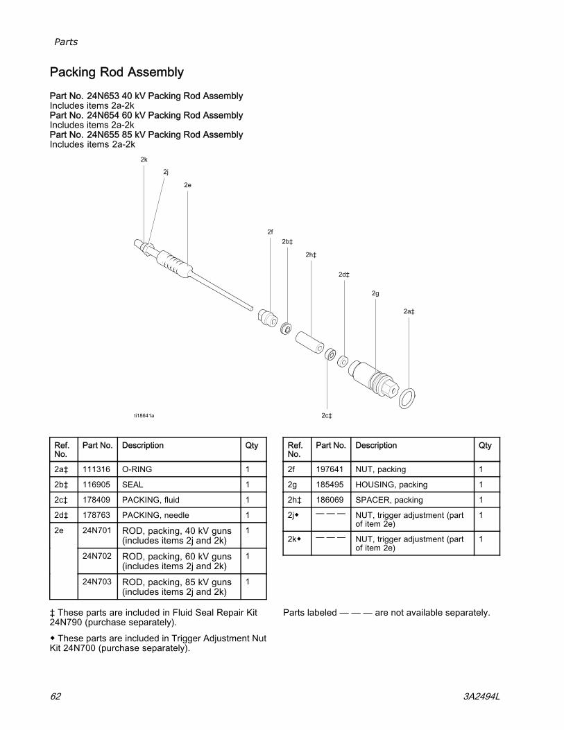
Parts
Packing Rod Assembly
Part No. 24N653 40 kV Packing Rod AssemblyIncludes items 2a-2kPart No. 24N654 60 kV Packing Rod AssemblyIncludes items 2a-2kPart No. 24N655 85 kV Packing Rod AssemblyIncludes items 2a-2k
Ref.No.
Part No. Description Qty
2a‡ 111316 O-RING 1
2b‡ 116905 SEAL 1
2c‡ 178409 PACKING, fluid 1
2d‡ 178763 PACKING, needle 1
24N701 ROD, packing, 40 kV guns(includes items 2j and 2k)
1
24N702 ROD, packing, 60 kV guns(includes items 2j and 2k)
1
2e
24N703 ROD, packing, 85 kV guns(includes items 2j and 2k)
1
Ref.No.
Part No. Description Qty
2f 197641 NUT, packing 1
2g 185495 HOUSING, packing 1
2h‡ 186069 SPACER, packing 1
2j◆ — — — NUT, trigger adjustment (partof item 2e)
1
2k◆ — — — NUT, trigger adjustment (partof item 2e)
1
‡ These parts are included in Fluid Seal Repair Kit24N790 (purchase separately).
◆ These parts are included in Trigger Adjustment NutKit 24N700 (purchase separately).
Parts labeled — — — are not available separately.
62 3A2494L
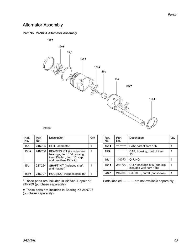
Parts
Alternator Assembly
Part No. 24N664 Alternator Assembly
Ref.No.
PartNo.
Description Qty
15a 24N705 COIL, alternator 1
15b♦ 24N706 BEARING KIT (includes twobearings, item 15d housing,item 15e fan, item 15f cap,and one item 15h clip)
1
15c 24Y264 SHAFT KIT (includes shaftand magnet)
1
15d♦ 24N707 HOUSING; includes item 15f 1
Ref.No.
PartNo.
Description Qty
15e♦ ——— FAN; part of item 15b 1
15f♦ ——— CAP, housing; part of item15d
1
15g* 110073 O-RING 1
15h♦ 24N709 CLIP; package of 5 (one clipincluded with item 15b)
1
28♦* 24N699 GASKET, barrel (not shown) 1
* These parts are included in Air Seal Repair Kit24N789 (purchase separately).
♦ These parts are included in Bearing Kit 24N706(purchase separately).
Parts labeled — — — are not available separately.
3A2494L 63
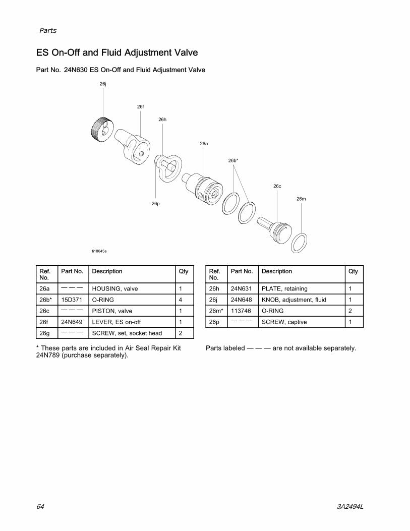
Parts
ES On-Off and Fluid Adjustment Valve
Part No. 24N630 ES On-Off and Fluid Adjustment Valve
Ref.No.
Part No. Description Qty
26a — — — HOUSING, valve 1
26b* 15D371 O-RING 4
26c — — — PISTON, valve 1
26f 24N649 LEVER, ES on-off 1
26g — — — SCREW, set, socket head 2
Ref.No.
Part No. Description Qty
26h 24N631 PLATE, retaining 1
26j 24N648 KNOB, adjustment, fluid 1
26m* 113746 O-RING 2
26p — — — SCREW, captive 1
* These parts are included in Air Seal Repair Kit24N789 (purchase separately).
Parts labeled — — — are not available separately.
64 3A2494L
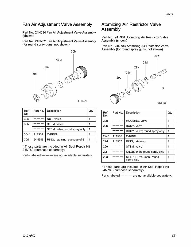
Parts
Fan Air Adjustment Valve Assembly
Part No. 24N634 Fan Air Adjustment Valve Assembly(shown)
Part No. 24N732 Fan Air Adjustment Valve Assembly(for round spray guns, not shown)
Ref.No.
Part No. Description Qty
30a — — — NUT, valve 1— — — STEM, valve 130b— — — STEM, valve; round spray only 1
30c* 111504 O-RING 1
30d 24N646 RING, retaining; package of 6 1
* These parts are included in Air Seal Repair Kit24N789 (purchase separately).
Parts labeled — — — are not available separately.
Atomizing Air Restrictor ValveAssemblyPart No. 24T304 Atomizing Air Restrictor ValveAssembly (shown)
Part No. 24N733 Atomizing Air Restrictor ValveAssembly (for round spray guns, not shown)
Ref.No.
Part No. Description Qty
29a — — — HOUSING, valve 1— — — BODY, valve 129b— — — BODY, valve; round spray only 1
29c* 111516 O-RING 1
29d 118907 RING, retaining 1
29e — — — STEM, valve 1
29f — — — KNOB, shaft; round spray only 1
29g — — — SETSCREW, knob; roundspray only
1
* These parts are included in Air Seal Repair Kit24N789 (purchase separately).
Parts labeled — — — are not available separately.
3A2494L 65
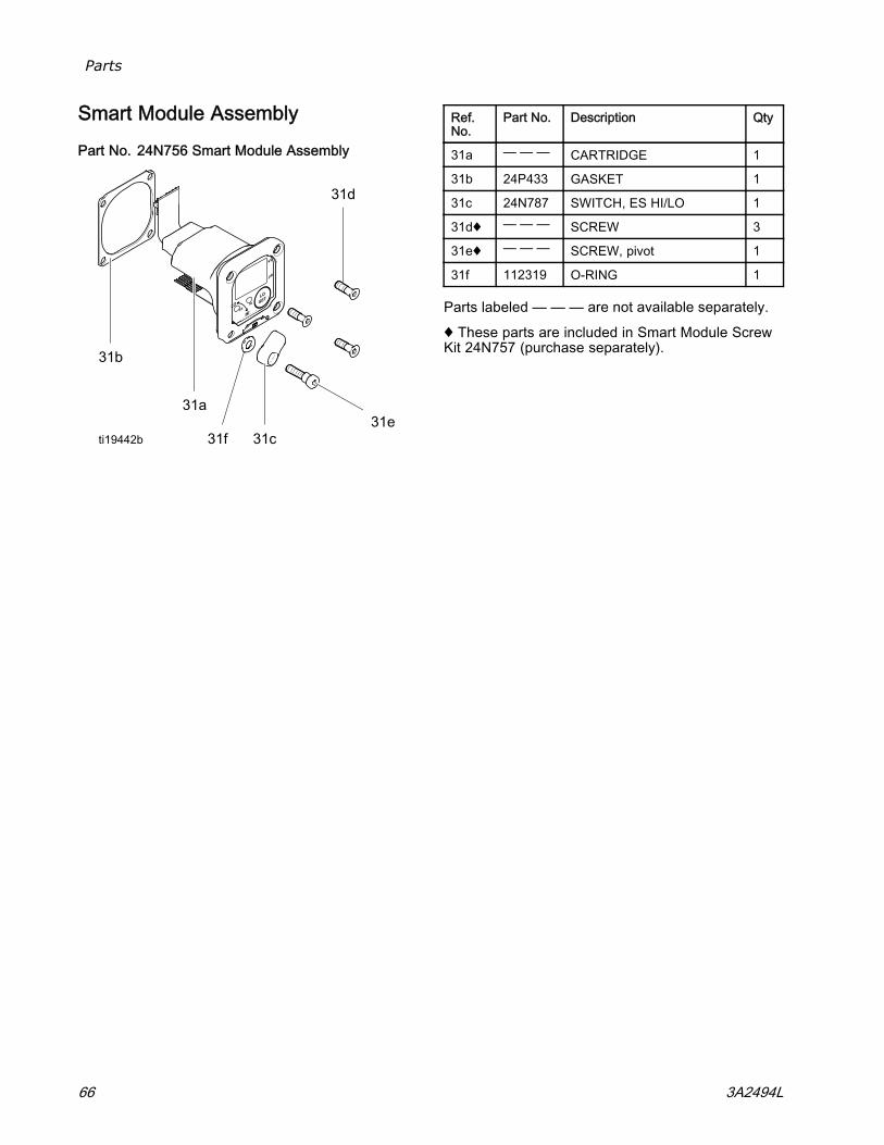
Parts
Smart Module Assembly
Part No. 24N756 Smart Module Assembly
Ref.No.
Part No. Description Qty
31a — — — CARTRIDGE 1
31b 24P433 GASKET 1
31c 24N787 SWITCH, ES HI/LO 1
31d♦ — — — SCREW 3
31e♦ — — — SCREW, pivot 1
31f 112319 O-RING 1
Parts labeled — — — are not available separately.
♦ These parts are included in Smart Module ScrewKit 24N757 (purchase separately).
66 3A2494L
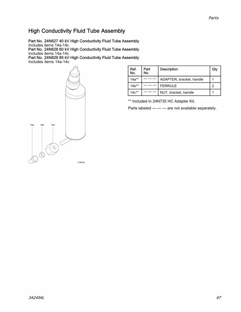
Parts
High Conductivity Fluid Tube Assembly
Part No. 24N627 40 kV High Conductivity Fluid Tube AssemblyIncludes items 14a-14cPart No. 24N628 60 kV High Conductivity Fluid Tube AssemblyIncludes items 14a-14cPart No. 24N629 85 kV High Conductivity Fluid Tube AssemblyIncludes items 14a-14c
Ref.No.
PartNo.
Description Qty
14a** — — — ADAPTER, bracket, handle 1
14b** — — — FERRULE 2
14c** — — — NUT, bracket, handle 1
** Included in 24N735 HC Adapter Kit.
Parts labeled — — — are not available separately.
3A2494L 67
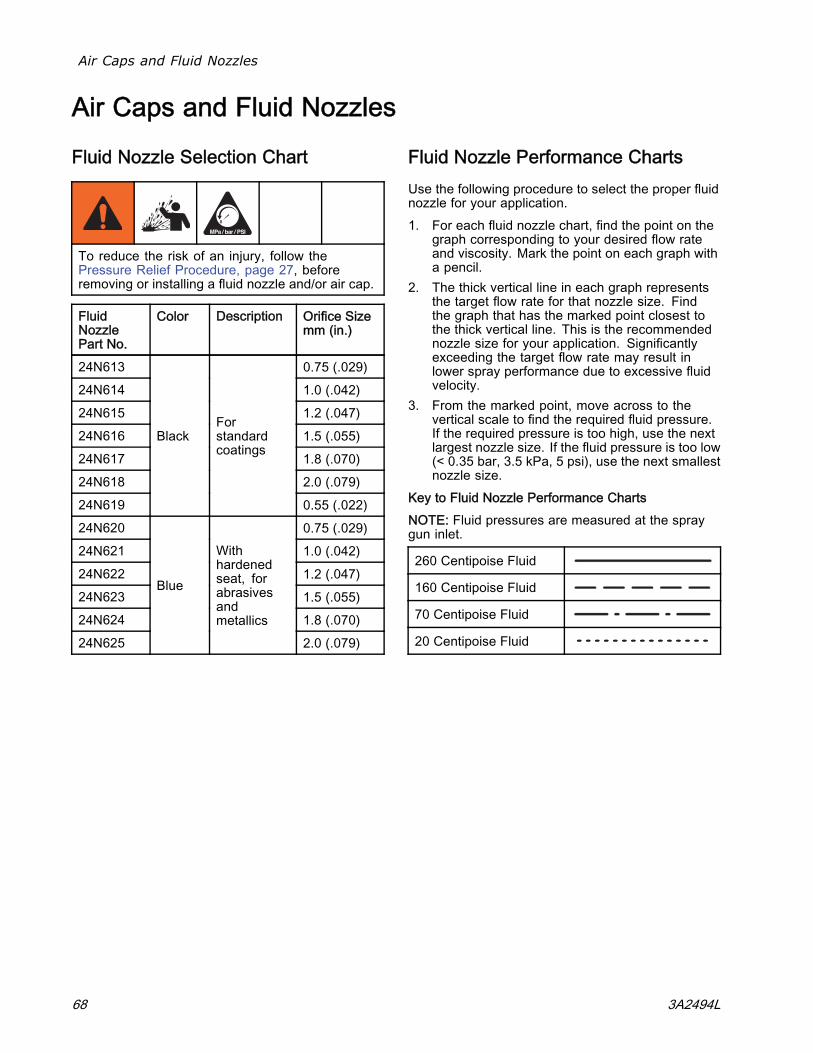
Air Caps and Fluid Nozzles
Air Caps and Fluid Nozzles
Fluid Nozzle Selection Chart
To reduce the risk of an injury, follow thePressure Relief Procedure, page 27, beforeremoving or installing a fluid nozzle and/or air cap.
FluidNozzlePart No.
Color Description Orifice Sizemm (in.)
24N613 0.75 (.029)24N614 1.0 (.042)24N615 1.2 (.047)24N616 1.5 (.055)24N617 1.8 (.070)24N618 2.0 (.079)24N619
BlackForstandardcoatings
0.55 (.022)24N620 0.75 (.029)24N621 1.0 (.042)24N622 1.2 (.047)24N623 1.5 (.055)24N624 1.8 (.070)24N625
Blue
Withhardenedseat, forabrasivesandmetallics
2.0 (.079)
Fluid Nozzle Performance ChartsUse the following procedure to select the proper fluidnozzle for your application.1. For each fluid nozzle chart, find the point on the
graph corresponding to your desired flow rateand viscosity. Mark the point on each graph witha pencil.
2. The thick vertical line in each graph representsthe target flow rate for that nozzle size. Findthe graph that has the marked point closest tothe thick vertical line. This is the recommendednozzle size for your application. Significantlyexceeding the target flow rate may result inlower spray performance due to excessive fluidvelocity.
3. From the marked point, move across to thevertical scale to find the required fluid pressure.If the required pressure is too high, use the nextlargest nozzle size. If the fluid pressure is too low(< 0.35 bar, 3.5 kPa, 5 psi), use the next smallestnozzle size.
Key to Fluid Nozzle Performance ChartsNOTE: Fluid pressures are measured at the spraygun inlet.
260 Centipoise Fluid
160 Centipoise Fluid
70 Centipoise Fluid
20 Centipoise Fluid
68 3A2494L
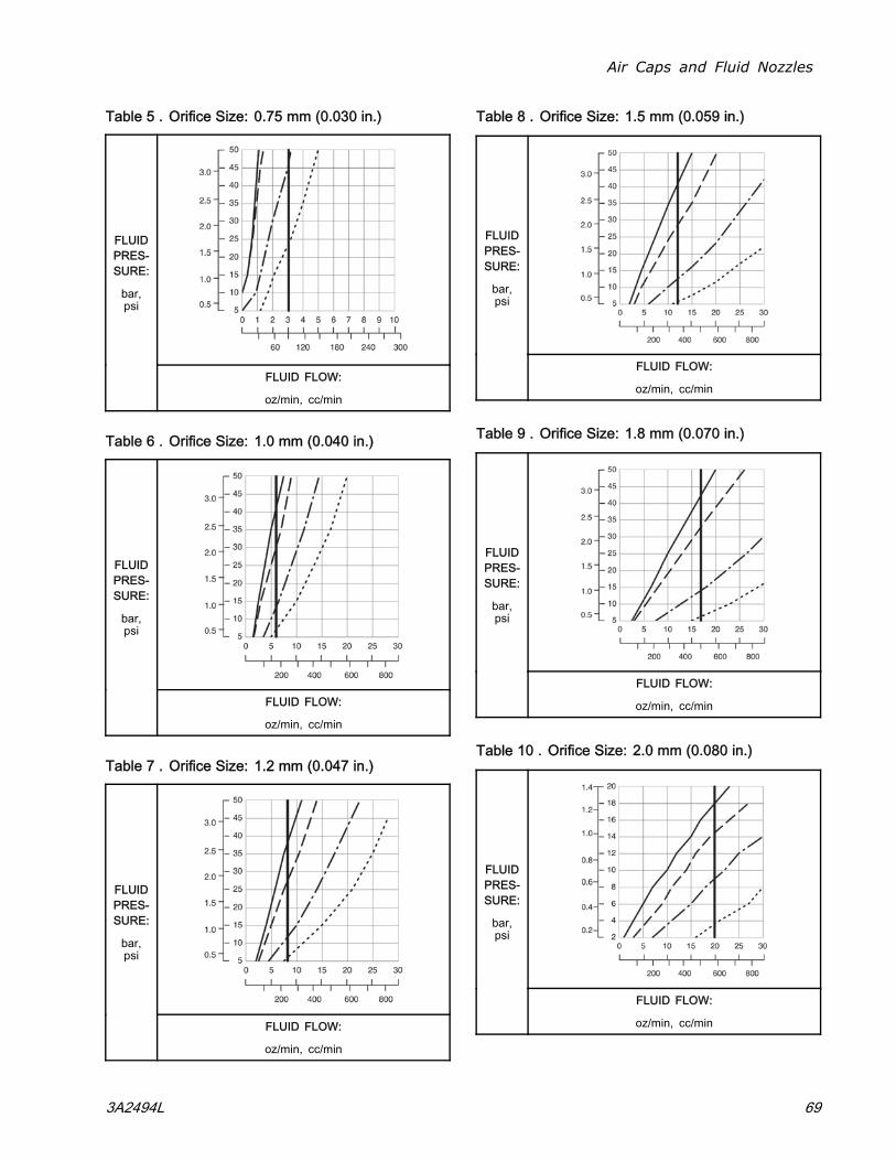
Air Caps and Fluid Nozzles
Table 5 . Orifice Size: 0.75 mm (0.030 in.)
FLUIDPRES-SURE:
bar,psi
FLUID FLOW:
oz/min, cc/min
Table 6 . Orifice Size: 1.0 mm (0.040 in.)
FLUIDPRES-SURE:
bar,psi
FLUID FLOW:
oz/min, cc/min
Table 7 . Orifice Size: 1.2 mm (0.047 in.)
FLUIDPRES-SURE:
bar,psi
FLUID FLOW:
oz/min, cc/min
Table 8 . Orifice Size: 1.5 mm (0.059 in.)
FLUIDPRES-SURE:
bar,psi
FLUID FLOW:
oz/min, cc/min
Table 9 . Orifice Size: 1.8 mm (0.070 in.)
FLUIDPRES-SURE:
bar,psi
FLUID FLOW:
oz/min, cc/min
Table 10 . Orifice Size: 2.0 mm (0.080 in.)
FLUIDPRES-SURE:
bar,psi
FLUID FLOW:
oz/min, cc/min
3A2494L 69
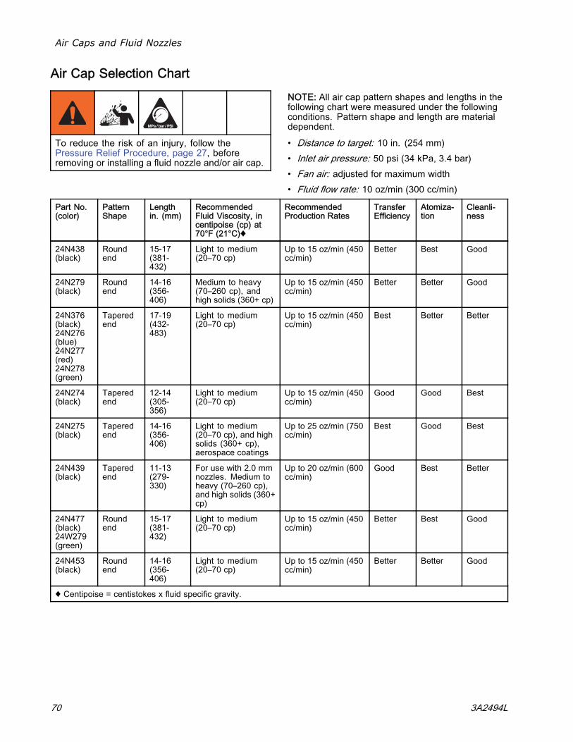
Air Caps and Fluid Nozzles
Air Cap Selection Chart
To reduce the risk of an injury, follow thePressure Relief Procedure, page 27, beforeremoving or installing a fluid nozzle and/or air cap.
NOTE: All air cap pattern shapes and lengths in thefollowing chart were measured under the followingconditions. Pattern shape and length are materialdependent.
• Distance to target: 10 in. (254 mm)• Inlet air pressure: 50 psi (34 kPa, 3.4 bar)• Fan air: adjusted for maximum width• Fluid flow rate: 10 oz/min (300 cc/min)
Part No.(color)
PatternShape
Lengthin. (mm)
RecommendedFluid Viscosity, incentipoise (cp) at70°F (21°C)♦
RecommendedProduction Rates
TransferEfficiency
Atomiza-tion
Cleanli-ness
24N438(black)
Roundend
15-17(381-432)
Light to medium(20–70 cp)
Up to 15 oz/min (450cc/min)
Better Best Good
24N279(black)
Roundend
14-16(356-406)
Medium to heavy(70–260 cp), andhigh solids (360+ cp)
Up to 15 oz/min (450cc/min)
Better Better Good
24N376(black)24N276(blue)24N277(red)24N278(green)
Taperedend
17-19(432-483)
Light to medium(20–70 cp)
Up to 15 oz/min (450cc/min)
Best Better Better
24N274(black)
Taperedend
12-14(305-356)
Light to medium(20–70 cp)
Up to 15 oz/min (450cc/min)
Good Good Best
24N275(black)
Taperedend
14-16(356-406)
Light to medium(20–70 cp), and highsolids (360+ cp),aerospace coatings
Up to 25 oz/min (750cc/min)
Best Good Best
24N439(black)
Taperedend
11-13(279-330)
For use with 2.0 mmnozzles. Medium toheavy (70–260 cp),and high solids (360+cp)
Up to 20 oz/min (600cc/min)
Good Best Better
24N477(black)24W279(green)
Roundend
15-17(381-432)
Light to medium(20–70 cp)
Up to 15 oz/min (450cc/min)
Better Best Good
24N453(black)
Roundend
14-16(356-406)
Light to medium(20–70 cp)
Up to 15 oz/min (450cc/min)
Better Better Good
♦ Centipoise = centistokes x fluid specific gravity.
70 3A2494L
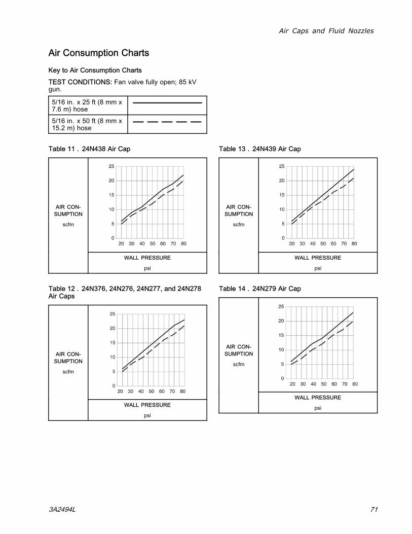
Air Caps and Fluid Nozzles
Air Consumption Charts
Key to Air Consumption Charts
TEST CONDITIONS: Fan valve fully open; 85 kVgun.
5/16 in. x 25 ft (8 mm x7.6 m) hose5/16 in. x 50 ft (8 mm x15.2 m) hose
Table 11 . 24N438 Air Cap
AIR CON-SUMPTION
scfm
WALL PRESSURE
psi
Table 12 . 24N376, 24N276, 24N277, and 24N278Air Caps
AIR CON-SUMPTION
scfm
WALL PRESSURE
psi
Table 13 . 24N439 Air Cap
AIR CON-SUMPTION
scfm
WALL PRESSURE
psi
Table 14 . 24N279 Air Cap
AIR CON-SUMPTION
scfm
WALL PRESSURE
psi
3A2494L 71
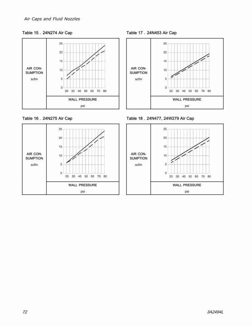
Air Caps and Fluid Nozzles
Table 15 . 24N274 Air Cap
AIR CON-SUMPTION
scfm
WALL PRESSURE
psi
Table 16 . 24N275 Air Cap
AIR CON-SUMPTION
scfm
WALL PRESSURE
psi
Table 17 . 24N453 Air Cap
AIR CON-SUMPTION
scfm
WALL PRESSURE
psi
Table 18 . 24N477, 24W279 Air Cap
AIR CON-SUMPTION
scfm
WALL PRESSURE
psi
72 3A2494L
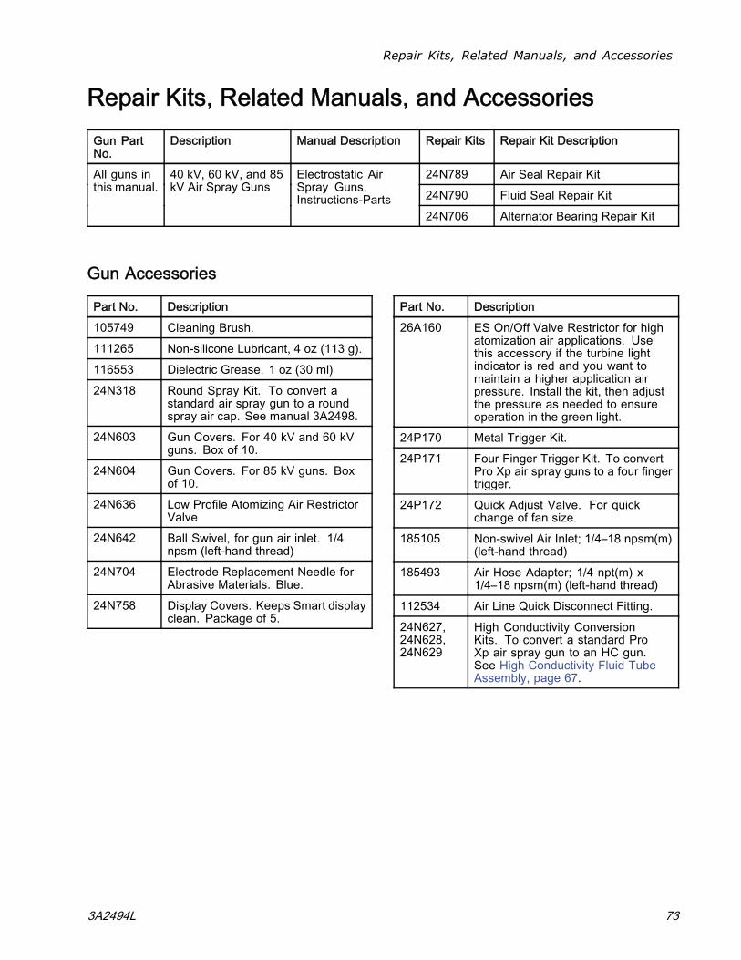
Repair Kits, Related Manuals, and Accessories
Repair Kits, Related Manuals, and AccessoriesGun PartNo.
Description Manual Description Repair Kits Repair Kit Description
24N789 Air Seal Repair Kit24N790 Fluid Seal Repair Kit
All guns inthis manual.
40 kV, 60 kV, and 85kV Air Spray Guns
Electrostatic AirSpray Guns,Instructions-Parts
24N706 Alternator Bearing Repair Kit
Gun Accessories
Part No. Description105749 Cleaning Brush.111265 Non-silicone Lubricant, 4 oz (113 g).116553 Dielectric Grease. 1 oz (30 ml)24N318 Round Spray Kit. To convert a
standard air spray gun to a roundspray air cap. See manual 3A2498.
24N603 Gun Covers. For 40 kV and 60 kVguns. Box of 10.
24N604 Gun Covers. For 85 kV guns. Boxof 10.
24N636 Low Profile Atomizing Air RestrictorValve
24N642 Ball Swivel, for gun air inlet. 1/4npsm (left-hand thread)
24N704 Electrode Replacement Needle forAbrasive Materials. Blue.
24N758 Display Covers. Keeps Smart displayclean. Package of 5.
Part No. Description26A160 ES On/Off Valve Restrictor for high
atomization air applications. Usethis accessory if the turbine lightindicator is red and you want tomaintain a higher application airpressure. Install the kit, then adjustthe pressure as needed to ensureoperation in the green light.
24P170 Metal Trigger Kit.24P171 Four Finger Trigger Kit. To convert
Pro Xp air spray guns to a four fingertrigger.
24P172 Quick Adjust Valve. For quickchange of fan size.
185105 Non-swivel Air Inlet; 1/4–18 npsm(m)(left-hand thread)
185493 Air Hose Adapter; 1/4 npt(m) x1/4–18 npsm(m) (left-hand thread)
112534 Air Line Quick Disconnect Fitting.24N627,24N628,24N629
High Conductivity ConversionKits. To convert a standard ProXp air spray gun to an HC gun.See High Conductivity Fluid TubeAssembly, page 67.
3A2494L 73
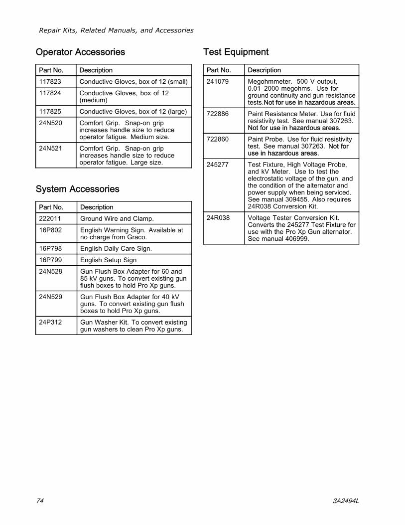
Repair Kits, Related Manuals, and Accessories
Operator Accessories
Part No. Description117823 Conductive Gloves, box of 12 (small)117824 Conductive Gloves, box of 12
(medium)117825 Conductive Gloves, box of 12 (large)24N520 Comfort Grip. Snap-on grip
increases handle size to reduceoperator fatigue. Medium size.
24N521 Comfort Grip. Snap-on gripincreases handle size to reduceoperator fatigue. Large size.
System Accessories
Part No. Description222011 Ground Wire and Clamp.16P802 English Warning Sign. Available at
no charge from Graco.16P798 English Daily Care Sign.16P799 English Setup Sign24N528 Gun Flush Box Adapter for 60 and
85 kV guns. To convert existing gunflush boxes to hold Pro Xp guns.
24N529 Gun Flush Box Adapter for 40 kVguns. To convert existing gun flushboxes to hold Pro Xp guns.
24P312 Gun Washer Kit. To convert existinggun washers to clean Pro Xp guns.
Test Equipment
Part No. Description241079 Megohmmeter. 500 V output,
0.01–2000 megohms. Use forground continuity and gun resistancetests.Not for use in hazardous areas.
722886 Paint Resistance Meter. Use for fluidresistivity test. See manual 307263.Not for use in hazardous areas.
722860 Paint Probe. Use for fluid resistivitytest. See manual 307263. Not foruse in hazardous areas.
245277 Test Fixture, High Voltage Probe,and kV Meter. Use to test theelectrostatic voltage of the gun, andthe condition of the alternator andpower supply when being serviced.See manual 309455. Also requires24R038 Conversion Kit.
24R038 Voltage Tester Conversion Kit.Converts the 245277 Test Fixture foruse with the Pro Xp Gun alternator.See manual 406999.
74 3A2494L
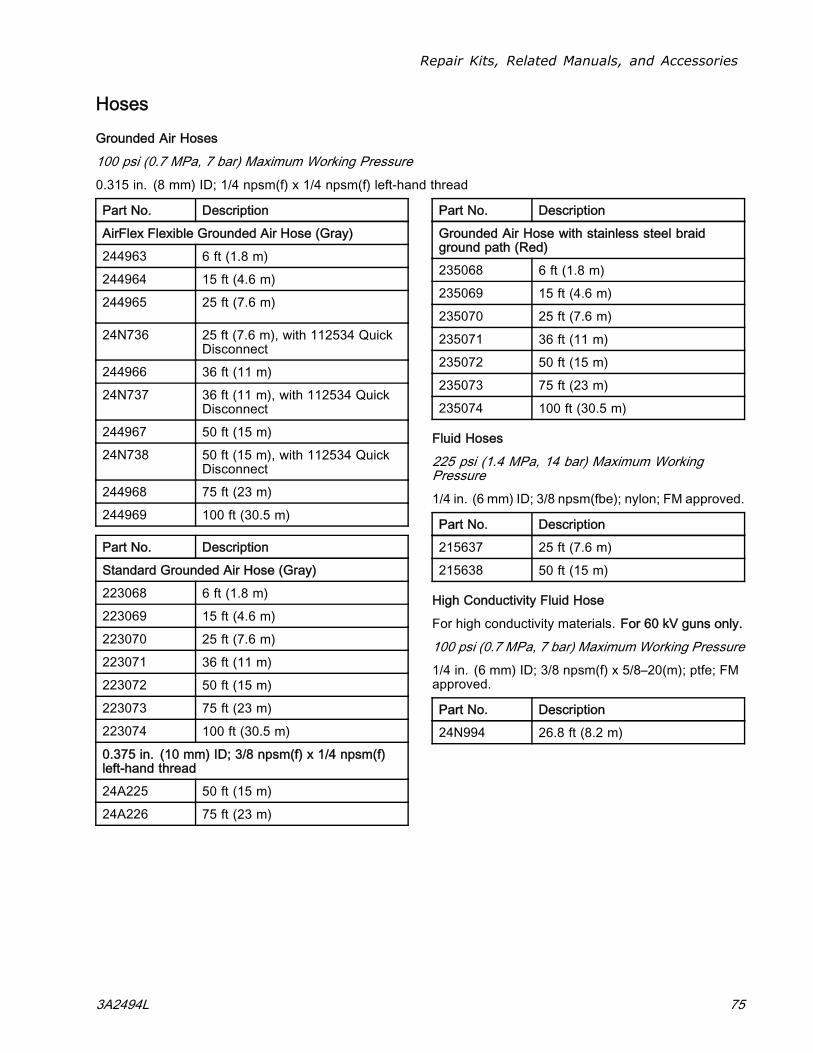
Repair Kits, Related Manuals, and Accessories
Hoses
Grounded Air Hoses
100 psi (0.7 MPa, 7 bar) Maximum Working Pressure0.315 in. (8 mm) ID; 1/4 npsm(f) x 1/4 npsm(f) left-hand thread
Part No. DescriptionAirFlex Flexible Grounded Air Hose (Gray)244963 6 ft (1.8 m)244964 15 ft (4.6 m)244965 25 ft (7.6 m)
24N736 25 ft (7.6 m), with 112534 QuickDisconnect
244966 36 ft (11 m)24N737 36 ft (11 m), with 112534 Quick
Disconnect244967 50 ft (15 m)24N738 50 ft (15 m), with 112534 Quick
Disconnect244968 75 ft (23 m)244969 100 ft (30.5 m)
Part No. DescriptionStandard Grounded Air Hose (Gray)223068 6 ft (1.8 m)223069 15 ft (4.6 m)223070 25 ft (7.6 m)223071 36 ft (11 m)223072 50 ft (15 m)223073 75 ft (23 m)223074 100 ft (30.5 m)0.375 in. (10 mm) ID; 3/8 npsm(f) x 1/4 npsm(f)left-hand thread24A225 50 ft (15 m)24A226 75 ft (23 m)
Part No. DescriptionGrounded Air Hose with stainless steel braidground path (Red)235068 6 ft (1.8 m)235069 15 ft (4.6 m)235070 25 ft (7.6 m)235071 36 ft (11 m)235072 50 ft (15 m)235073 75 ft (23 m)235074 100 ft (30.5 m)
Fluid Hoses
225 psi (1.4 MPa, 14 bar) Maximum WorkingPressure1/4 in. (6 mm) ID; 3/8 npsm(fbe); nylon; FM approved.
Part No. Description215637 25 ft (7.6 m)215638 50 ft (15 m)
High Conductivity Fluid Hose
For high conductivity materials. For 60 kV guns only.
100 psi (0.7 MPa, 7 bar) Maximum Working Pressure1/4 in. (6 mm) ID; 3/8 npsm(f) x 5/8–20(m); ptfe; FMapproved.
Part No. Description24N994 26.8 ft (8.2 m)
3A2494L 75
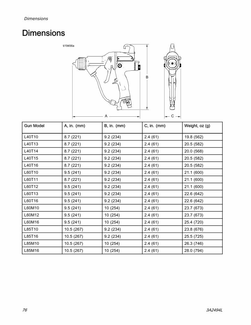
Dimensions
Dimensions
Gun Model A, in. (mm) B, in. (mm) C, in. (mm) Weight, oz (g)
L40T10 8.7 (221) 9.2 (234) 2.4 (61) 19.8 (562)L40T13 8.7 (221) 9.2 (234) 2.4 (61) 20.5 (582)L40T14 8.7 (221) 9.2 (234) 2.4 (61) 20.0 (568)L40T15 8.7 (221) 9.2 (234) 2.4 (61) 20.5 (582)L40T16 8.7 (221) 9.2 (234) 2.4 (61) 20.5 (582)L60T10 9.5 (241) 9.2 (234) 2.4 (61) 21.1 (600)L60T11 8.7 (221) 9.2 (234) 2.4 (61) 21.1 (600)L60T12 9.5 (241) 9.2 (234) 2.4 (61) 21.1 (600)L60T13 9.5 (241) 9.2 (234) 2.4 (61) 22.6 (642)L60T16 9.5 (241) 9.2 (234) 2.4 (61) 22.6 (642)L60M10 9.5 (241) 10 (254) 2.4 (61) 23.7 (673)L60M12 9.5 (241) 10 (254) 2.4 (61) 23.7 (673)L60M16 9.5 (241) 10 (254) 2.4 (61) 25.4 (720)L85T10 10.5 (267) 9.2 (234) 2.4 (61) 23.8 (676)L85T16 10.5 (267) 9.2 (234) 2.4 (61) 25.5 (725)L85M10 10.5 (267) 10 (254) 2.4 (61) 26.3 (746)L85M16 10.5 (267) 10 (254) 2.4 (61) 28.0 (794)
76 3A2494L
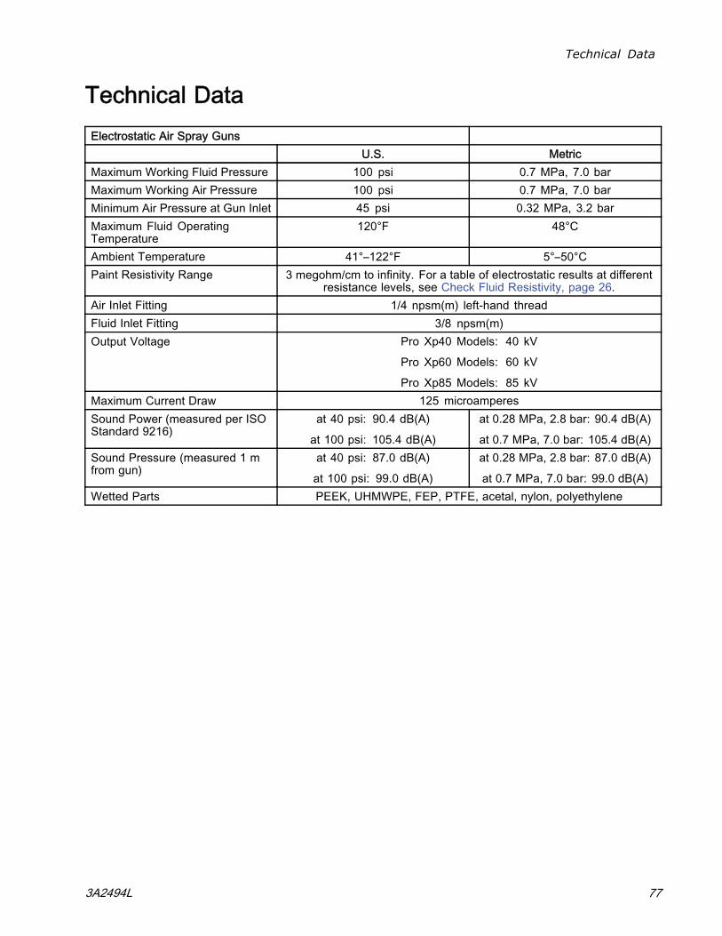
Technical Data
Technical DataElectrostatic Air Spray Guns
U.S. MetricMaximum Working Fluid Pressure 100 psi 0.7 MPa, 7.0 barMaximum Working Air Pressure 100 psi 0.7 MPa, 7.0 barMinimum Air Pressure at Gun Inlet 45 psi 0.32 MPa, 3.2 barMaximum Fluid OperatingTemperature
120°F 48°C
Ambient Temperature 41°–122°F 5°–50°CPaint Resistivity Range 3 megohm/cm to infinity. For a table of electrostatic results at different
resistance levels, see Check Fluid Resistivity, page 26.Air Inlet Fitting 1/4 npsm(m) left-hand threadFluid Inlet Fitting 3/8 npsm(m)Output Voltage Pro Xp40 Models: 40 kV
Pro Xp60 Models: 60 kV
Pro Xp85 Models: 85 kVMaximum Current Draw 125 microamperesSound Power (measured per ISOStandard 9216)
at 40 psi: 90.4 dB(A)
at 100 psi: 105.4 dB(A)
at 0.28 MPa, 2.8 bar: 90.4 dB(A)
at 0.7 MPa, 7.0 bar: 105.4 dB(A)Sound Pressure (measured 1 mfrom gun)
at 40 psi: 87.0 dB(A)
at 100 psi: 99.0 dB(A)
at 0.28 MPa, 2.8 bar: 87.0 dB(A)
at 0.7 MPa, 7.0 bar: 99.0 dB(A)Wetted Parts PEEK, UHMWPE, FEP, PTFE, acetal, nylon, polyethylene
3A2494L 77

Graco Pro Xp Warranty
Graco warrants all equipment referenced in this document which is manufactured by Graco and bearing its nameto be free from defects in material and workmanship on the date of sale to the original purchaser for use. With theexception of any special, extended, or limited warranty published by Graco, Graco will, for a period of twelve monthsfrom the date of sale, repair or replace any part of the equipment determined by Graco to be defective. However, anydeficiency in the barrel, handle, trigger, hook, internal power supply, and alternator (excluding turbine bearings) will berepaired or replaced for thirty-six months from the date of sale. This warranty applies only when the equipment isinstalled, operated and maintained in accordance with Graco’s written recommendations.This warranty does not cover, and Graco shall not be liable for general wear and tear, or any malfunction, damageor wear caused by faulty installation, misapplication, abrasion, corrosion, inadequate or improper maintenance,negligence, accident, tampering, or substitution of non-Graco component parts. Nor shall Graco be liable formalfunction, damage or wear caused by the incompatibility of Graco equipment with structures, accessories,equipment or materials not supplied by Graco, or the improper design, manufacture, installation, operation ormaintenance of structures, accessories, equipment or materials not supplied by Graco.This warranty is conditioned upon the prepaid return of the equipment claimed to be defective to an authorizedGraco distributor for verification of the claimed defect. If the claimed defect is verified, Graco will repair or replacefree of charge any defective parts. The equipment will be returned to the original purchaser transportation prepaid.If inspection of the equipment does not disclose any defect in material or workmanship, repairs will be made at areasonable charge, which charges may include the costs of parts, labor, and transportation.THIS WARRANTY IS EXCLUSIVE, AND IS IN LIEU OF ANY OTHER WARRANTIES, EXPRESS OR IMPLIED,INCLUDING BUT NOT LIMITED TO WARRANTY OF MERCHANTABILITY OR WARRANTY OF FITNESS FOR APARTICULAR PURPOSE.Graco’s sole obligation and buyer’s sole remedy for any breach of warranty shall be as set forth above. The buyeragrees that no other remedy (including, but not limited to, incidental or consequential damages for lost profits, lostsales, injury to person or property, or any other incidental or consequential loss) shall be available. Any action forbreach of warranty must be brought within two (2) years of the date of sale.GRACO MAKES NO WARRANTY, AND DISCLAIMS ALL IMPLIED WARRANTIES OF MERCHANTABILITY ANDFITNESS FOR A PARTICULAR PURPOSE, IN CONNECTION WITH ACCESSORIES, EQUIPMENT, MATERIALSOR COMPONENTS SOLD BUT NOT MANUFACTURED BY GRACO. These items sold, but not manufactured byGraco (such as electric motors, switches, hose, etc.), are subject to the warranty, if any, of their manufacturer. Gracowill provide purchaser with reasonable assistance in making any claim for breach of these warranties.In no event will Graco be liable for indirect, incidental, special or consequential damages resulting from Gracosupplying equipment hereunder, or the furnishing, performance, or use of any products or other goods sold hereto,whether due to a breach of contract, breach of warranty, the negligence of Graco, or otherwise.FOR GRACO CANADA CUSTOMERSThe Parties acknowledge that they have required that the present document, as well as all documents, notices andlegal proceedings entered into, given or instituted pursuant hereto or relating directly or indirectly hereto, be drawnup in English. Les parties reconnaissent avoir convenu que la rédaction du présente document sera en Anglais,ainsi que tous documents, avis et procédures judiciaires exécutés, donnés ou intentés, à la suite de ou en rapport,directement ou indirectement, avec les procédures concernées.
Graco InformationFor the latest information about Graco products, visit www.graco.com.For patent information, see www.graco.com/patents.
To place an order, contact your Graco Distributor or call to identify the nearest distributor.Phone: 612-623-6921 or Toll Free: 1-800-328-0211 Fax: 612-378-3505
All written and visual data contained in this document reflects the latest product information available at the time of publication.
Graco reserves the right to make changes at any time without notice.
Original Instructions. This manual contains English, MM 3A2494
Graco Headquarters: Minneapolis
International Offices: Belgium, China, Japan, Korea
GRACO INC. AND SUBSIDIARIES • P.O. BOX 1441 • MINNEAPOLIS, MN 55440-1441 • USA
Copyright 2012, Graco Inc. All Graco manufacturing locations are registered to ISO 9001.
www.graco.com
Revision L, March 2017