INSTRUCTIONS FOR SUPERIOR SLO-SYN TD SERIES BRUSHLESS ...
24
PRICE:$12.50 INSTRUCTIONS FOR SUPERIOR SLO-SYN TD SERIES BRUSHLESS SERVO DRIVES
Transcript of INSTRUCTIONS FOR SUPERIOR SLO-SYN TD SERIES BRUSHLESS ...

PRICE:$12.50
INSTRUCTIONSFOR
SUPERIOR SLO-SYNTD SERIES
BRUSHLESS SERVODRIVES

Dangerous voltages, currents, temperatures, and energy levels exist within thisunit, on certain accessible terminals, and in the servo motor(s) and motorwiring. Caution should be exercised when installing and applying this product. Only qualified personnel should attempt to utilize, install or operate thisproduct. It is essential that proper electrical practices, applicable electricalcodes, and the contents of this manual be followed.
Servo motors develop high torque and speed. Precautionary measures shouldbe used prior to performing any mechanical work or applying power to theunit. Proper preparations should be made ie. installation of limit switches, useof Following Error (in the Servo controller), power removal guards, etc. toavoid injury due to motor run away, motor oscillations, improper servo loopgains, etc..
Servo motors can have temperatures of up to or exceeding 100°°°°C. Use cautionwhen handling the motors. Where appropriate, guards should be used toprevent inadvertent contact with the motors.
ENGINEERING CHANGES
Superior Electric reserves the right to make engineering refinements on all its products. Such refinements may affectinformation given in instructions, Therefore, USE ONLY THE INSTRUCTIONS THAT ARE PACKED WITH THEPRODUCT.
©Superior Electric 1997
Warning
!Caution
!Caution

i
Table Of Contents
SECTIONS & TITLE PAGE
Things to Know Before Using This Equipment ii
1.0 - Introduction 1 1.1 - Using This Manual 1
1.2 - Product Features
2.0 - Specifications 2 2.1 - Mechanical and Environmental Specifications 2 2.2 - Electrical Specifications 2
2.3 - Signal Specifications 32.4 - LED Specifications 42.5 - Current Specifications 52.6 - Motor Specifications 5
3.0 - Installation 6 3.1 - Mounting 6 3.2 - General Wiring Guidelines 7 3.3 - AC Power Wiring 9 3.4 - Motor Wiring 10
3.5 - Regenerative Resistor Connections 11 3.6 - Control Wiring 12
4.0 - Operation 13 4.1 - Introduction 13 4.2 - Initial Start-Up 13 4.3 - Sequence of Operation 13
4.4 - Protective Features 14
5.0 - Troubleshooting Guide 15
Appendix A - CE Compliance Installation Requirements and Information 17
Warranty Information 19

ii
THINGS TO KNOW BEFORE GETTING STARTED
• Only qualified personnel should install or perform service on this equipment. Do not operate the unitwithout the enclosure as voltage present in this unit can cause serious or fatal injuries.
• Before performing any work on this unit or the wiring, allow at least 5 minutes for the capacitors to fullydischarge, to prevent electrical shock hazards.
• Motors powered by this unit develop high torque. Be sure to disconnect AC power before doing anymechanical work.
• When energizing the system, be aware that mechanical motion may occur. Be prepared to take theappropriate action to protect personnel and equipment.

Introduction 1
1.0 INTRODUCTION
1.1 Using This Manual
It is important that you understand how TD330 units operate before installing and using these products. Westrongly recommend that you read this manual completely before proceeding with the installation.
This manual is an installation and operating guide for the TD330/04 and the TD330/08 Torque ModeAmplifiers (Drives). Section 1 gives you an overview of the product functions and features. Section 2 givesdetailed information on the specifications for the product and pertinent system requirements. Section 3provides the recommended installation guidelines. Section 4 contains the recommended operatinginstructions for the system.
Other information included is a troubleshooting guide in Section 5, and warranty information.
1.2 Product Features
The TD330 drives are designed to operate hall commutation DC brushless motors. Alternatively, motorswith encoders having the appropriate commutation signals may be used. The amplifier operates in the torquemode which can be connected to a positioning system such as the Superior SLO-SYN MX2000 control. Aversion with a built-in single-axis controller is also available as the TDC330/04 and the TDC 330/08.
* Line operated 115/230 Vac input
* Switch selectable current scaling for easy installation (no potentiometers to adjust)
* Latched short circuit protection (phase to phase and phase to ground)
* Latched over temperature protection
* Latched DC bus over voltage protection
* Optically isolated inputs
* 50 ohm 50 watt regenerative energy circuit included

2 Specifications
2.0 SPECIFICATIONS
2.1 Mechanical and Environmental Specifications
Size: 2.88W x 10.63H x 8.07D (See Figure 3.1)Weight: TD330/04: 6.75 lbs.
TD330/08: 7.25 lbs.
Temperature: 0°C to 50°C (32°F to 122°F) operating -40°C to 75°C (-40°F to 167°F) storage
Max. Heatsink Temp: 70°C (158°F); forced air cooling may be necessary
Humidity: 95% maximum, non-condensing
Altitude: 10,000 feet max.
2.2 Electrical Specifications
Input Voltage: Single Phase 95 to 264 Vac, 50/60 Hz
Input Current: TD330/04, 7 amps, fuse rating: 8 amp 3AB Fast ActingTD330/08, 14 amps, fuse rating 15 amp 3AB Fast Acting
Internal Bus Voltage: 130 to 375 Vdc depending on AC Input Voltage
Motor Current: TD330/04, 4 amps continuous, 8 amps peak TD330/08, 8 amps continuous, 16 amps peak
(maximum value of a 6-step waveform)
Regenerative Energy Circuit: Internal: 50 ohm, 50 watt resistorExternal: Connections availableSee example for size selection in Section 3.5 or consult factory
Regenerative Energy Circuit Fusing: 1 amp 3AG Slo-Blo

Specifications 3
2
4
5
6
2.3 Signal Specifications
Figure 2.1I/O Signals
+5V and +5V COM: 5Vdc, 0.3 ampspower supply to be used for hall and/orencoder devices.
HALL 1, 2, 3: Optically isolated inputsfor the commutation devices. The inputsare pulled up to a +5 V supply through a1000 ohm resistor. Low level current isless than 4 milliamperes. See figure 2.1for details.
SHIELD: Connection to unit ground forcable shields.
CMD+, CMD-: The analog interface to anexternal controller. A voltage from +10 to-10 Volts between these two inputscommands the drive to deliver from +2Xfull current selected to -2X full currentselected to the motor. See figure 2.1 fordetails.
ENABLE: Optically isolated input whichwhen pulled low activates the drive. Theinput is pulled up to the +15 V supplythrough a 2200 ohm resistor. The lowlevel current is < 7 milliamps. See figure2.1 for details.
READY: A relay output with NO and NCcontacts. The relay activates when thedrive is ready. The contact current ratingis 0.5 amps at 24Vdc resistive load. See
figure 2.1 for details.
+24V & 24V COM: Isolated DC supplyfor customer use rated 24 Vdc +/- 10% and0.5 amps. See figure 2.1 for details.
1
2
3
4
5
6
7
1
3
7

4 Specifications
2.4 LED Specifications
Figure 2.2LED’s
Power LED: The power LED indicates that there is AC power applied to the driveand that the logic supply is active.
Over Current LED: The over current LED, when active, indicates the possibility of a shortcircuit from phase to ground or phase to phase. It may also be causedby a non-compatible motor being used.
Over temperature LED: This LED shows that the unit has shut down due to an overtemperature situation, which could be caused by the temperature ofthe heat sink being in excess of 70 °C (158°F) or the ambienttemperature is greater than 50 °C (122°F).
Regen on LED: When this LED is on the regenerative circuitry is active. It does notindicate a fault.
Over Current LED If the over current and the over temperature LED’s are active & this indicates that an over voltage condition has occurred, busOver temperature LED: voltage > 410VDC.
OVERCURRENT
OVERTEMPERATURE
REGEN ON
POWER
8
9
10 11
12
8
9
10
11
12

Specifications 5
2.5 Current Settings:
The current settings of the drive reflect the continuous current capability of the motor. Peak current is twicethe continuous current setting. The TD-04 has a maximum continuous current of 4 amps and a peak currentof 8 amps. The TD-08 has a maximum continuous current of 8 amps with 16 amps peak current. Thehighest DIP switch setting in the on position will be the max. continuous current supplied by the drive. Seefigure 2.3.
Figure 2.3Current Settings
2.6 Motor Specifications
Type: 3 Phase Brushless motor with Hall commutation or encoder with commutaion tracks
Voltage: Capable of withstanding bus voltages of 350 Volts.
Current: TD330/04 1 to 4 Amp continuous, 2 to 8 amp peak TD330/08 2 to 8 Amp continuous, 4 to 16 amp peak
RecommendedInductance: 4 mH minimum
NOTE: DUTY CYCLE LIMITING WILL BE REQUIRED TO KEEP THE SHELLTEMPERATURE BELOW ITS RATING.
CurrentSett ings
8.07.06.05.04.03.0
OFFON2.0 - ALL OFF
CURRENT
TD-04
TD-08

6 Installation
3.0 INSTALLATION
3.1 Mounting
The servo drive is intended to be mounted with the brackets supplied with the unit. When selecting amounting location, it is important to leave at least 2 inches unrestricted space around the top, bottom, andsides of the unit to allow for proper airflow for cooling. Keep the unit away from potential noise sourcesor sensitive electronic equipment.
NOTE: The unit should be mounted upright with the cooling fins vertical. The case temperature should notexceed 70 °C (158 °F). Forced air cooling may be required to keep the temperature within the stated limits.
Figure 3.1Outline Dimensions

Installation 7
3.2 General Wiring Guidelines
Dangerous voltages, currents, temperatures, and energy levels exist within thisunit, on certain accessible terminals, and at the servo motor. NEVER operatethe unit with its protective cover removed! Caution should be exercised wheninstalling and applying this product. Only qualified personnel should attemptto install and/or operate this product. It is essential that proper electricalpractices, applicable electrical codes and the contents of this manual be followedstrictly.
Superior SLO-SYN controls and drives use modern solid-state digital electronics to provide the featuresneeded for advanced motion control applications. Although care has been taken to ensure proper operationunder a wide range of conditions, some user equipment may produce considerable electromagneticinterference (EMI) which can cause inappropriate operation of the digital logic used in the control, drive,or other computer-type equipment in the user’s system.
In general, any equipment that causes arcs or sparks or that switches voltage or current at high frequenciescan cause interference. In addition, ac utility lines are often “polluted” with electrical noise from sourcesoutside a user’s control (such as equipment in the factory next door). Some of the more common causes ofelectrical interference are:
• power from the utility ac line• relays, contactors, and solenoids• light dimmers• arc welders• motors and motor starters• induction heaters• radio controls or transmitters• switch-mode power supplies• computer-based equipment• high frequency lighting equipment• dc servo and stepper motors and drives
The following wiring practices should be used to reduce noise interference.
Solid grounding of the system is essential. Be sure that there is a solid connection to the ac systemprotective earth ground (PE). Insure that there is a good electrical connection through the drive case to thecontrol system enclosure . A separate grounding strap may be required to properly ground the unit to thecontrol system enclosure. This strap should ideally be constructed using copper braid at least 0.5" in width. Use a single-point grounding system for all related components of the system (a “hub and spokes” arrange-ment). Keep the ground connection short and direct. Grounding through both a mechanical connection tothe control enclosure and through a grounding strap is optimal.
Warning

8 Installation
Keep power and signal wiring separated. Power wiring includes ac wiring, motor wires, etc. Signalwiring is inputs and outputs (I/O), encoder wiring, serial communications (RS232 lines), etc. If possible,use separate conduit or ducts for each. If the wires must cross, they should do so at right angles to minimizecoupling.
Use separately bundled shielded cables for the drive to motor, encoder, serial communications, analoginput, and digital I/O wiring. For motor connections, BE SURE TO GROUND THE SHIELD AT THESLO-SYN DRIVE END. For other connections it is recommended that the shields be terminated at the Slo-Syn unit as well. Shield connections are provided on the unit terminal connectors for this purpose. Allcable shielding should be terminated at ONE END ONLY. Grounding the serial communicationsconnections at the opposite end of the controller may be necessary in some systems. If the cable shield mustbe connected at the opposite end from the Slo-Syn unit, the shield should NOT also be connected at the unitas this may cause a “ground loop” and introduce electrical noise problems.
Suppress all relays as close to the coil as possible to prevent noise generation. Typical suppressors arediodes, capacitors or MOV’s. (See manufacturer's literature for complete information). Whenever possible,use solid-state relays instead of mechanical contact types to minimize noise generation.
In some extreme cases of interference, it may be necessary to add external filtering to the ac line(s) feedingthe affected equipment, or to use isolation transformers to supply their ac power.
NOTE: Superior Electric makes a wide range of ac power line conditioners that can help solve electricalinterference problems. Contact 1-800-SUP-ELEC (1-800-787-3532) for further assistance.
Installation 9
13
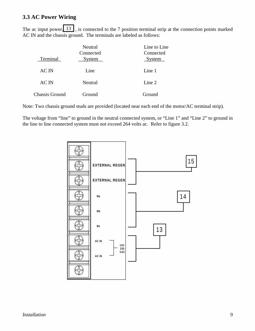
3.3 AC Power Wiring
The ac input power, , is connected to the 7 position terminal strip at the connection points markedAC IN and the chassis ground. The terminals are labeled as follows:
Neutral Line to LineConnected Connected
Terminal System System
AC IN Line Line 1
AC IN Neutral Line 2
Chassis Ground Ground Ground
Note: Two chassis ground studs are provided (located near each end of the motor/AC terminal strip).
The voltage from “line” to ground in the neutral connected system, or “Line 1” and “Line 2” to ground inthe line to line connected system must not exceed 264 volts ac. Refer to figure 3.2.
14
13
15EXTERNAL REGEN
EXTERNAL REGEN
Ma
Mb
Mc
AC IN
AC IN
115-230VAC

10 Installation
14
3.4 Motor Wiring
The motor wiring is connected to the 7 position terminal strip at the connection points marked Ma, Mb, andMc, . Refer to figure 3.2. The motor ground is connected to the Chassis Ground provided. Theterminals are marked as follows:
Terminal Connection
Ma Motor Phase A
Mb Motor Phase B
Mc Motor Phase C
Chassis Ground Motor Ground
Note: Two chassis ground studs are provided (located near each end of the motor/AC terminal strip).
Motor & Hall Sensor Commutation Table
HALL 1 HALL 2 HALL 3 MOTORVOLTAGE
+5 VDC 0V 0V Ma to Mb
0V +5VDC 0V Mb to Mc
0V 0V +5VDC Mc to Ma
The above table must be used to properly “phase” your motor’s windings to the three hall effect sensors orencoder commutation tracks.
Note: A pull-up resistor of 1Kohm to +5VDC is provided on the three HALL inputs internal to the driveunit. If an open-collector hall sensor is used, the device must be off to yield a +5VDC signal at the driveHALL terminal.
Reference figure 3.3 for additional information.

Installation 11
15
3.5 Regenerative Resistor Connections
An external regenerative resistor can be connected to the 7 position terminal strip connection points markedexternal regen, . Refer to Figure 3.2. See the following example to determine if an external regenerativeresistor is required.
For determining if the internal regenerative resistor is sufficient use the following formula:
Jrotor = Inertia of the rotor in lb-in-sec2
Jload = Inertia of the load in lb-in-sec2
P = Power of regen resistor in wattsN = Speed of the motor in RPMTfrict = Frictional torque in lb-intdecel = Deceleration timetcyc = Cycle timeE = energy in motor in joules
where: P = Power of the internal resistor = 50 W
The internal resistor is sufficient if the calculated energy is ≤ 200 Joules and the cycle time is greater thanthe calculated cycle time.
Example:Jrotor =.0026 lb in sec2
Jload = 0.130 lb in sec2
P = 50 WN = 4000Tfrict = 5 lb. in.tdecel = .25 sec
Since the energy is less than 200 joules and if the cycle time is greater than 1.9 seconds no external regenis required. If the energy is greater than 200 joules or the cycle time is less than the calculated cycle timeconsult the factory for the proper external regen resistor.
E= * (J rotor + J load ) * N 2 - * Tfrict * N * t decel
tcyc =
11 6 1 6
18 5
EP
E= * ( .0026 + . 0 1 3 0 ) * (4000) 2 - * 5 * 4000 * .25 = 95 .63
tcyc > > 1 .9
11 6 1 6
18 5
9 5 . 6 35 0

12 Installation
3.6 Control Wiring
The control wiring is grouped together on the terminal strip based on their origin. The hall sensor power andsignals get connected to the motor. The command signals, the enable, and the ready signal typically connectto the controller. (see Figure 2.1). The 24 volt supply is for customer use and is not ground referenced. Theuse of shielded cable is recommended. Refer to figure 3.3 for a typical installation utilizing a MX2000controller.
Figure 3.3Typical Control Wiring
+5V
5V COM
HALL 1
HALL 2
HALL 3
SHIELD
CMD +
CMD -
ENABLE
READY
READY
READY
+24V
24V COM
MX AnalogDrive I/O
Out
A G N D
E N +
EN-
R D Y +
RDY-

Operation 13
4.0 OPERATION
4.1 Introduction
The TD330 series operates as a torque mode amplifier. When the drive is enabled and there are no internalshutdowns, a voltage present between the CMD inputs gets translated into motor current. This currentcreates torque in the motor which yields a rotational force. When connected to a motion controller such asthe MX2000, the commanded voltage is issued from the MX2000. The drive’s output current is scaledbased on the selected dip switch setting (see Figure 2.3). The setting should be matched to the motor’sspecifications. Always refer to the controller manual to set up your motion control system.
4.2 Initial Start-Up
At this point your system should be wired including all safety devices and limit switches. The functionalityof these devices MUST be verified before proceeding with the drive activation. Be prepared to shutdownthe system in the event of servo loop problems that can include run away situations and motor oscillations.
4.3 Sequence of Operations
This section contains basic information for the start up of a drive and control system. Always refer to thecontroller manual for it’s operational characteristics.
1) Power up the controller that is connected to the TD330 drive.
ENSURE THAT THE FOLLOWING ERROR IS ENABLED TO PREVENT MOTORRUN AWAY CONDITIONS, SYSTEM DAMAGE, OR INJURY.
2) Verify the CMD signal to the drive is 0 volts and the enable signal is HIGH.
3) Power up the drive and verify the power LED is on. (There should be no motion at this time.)
4) Verify that there are no other drive LED’s on.
5) Have the controller enable the drive. BE PREPARED TO SHUTDOWN THE SYSTEM.
6) If operational problems occur, refer to the troubleshooting guide contained in this manual or in thecontroller manual.
!Caution

14 Operation
4.4 Protective Features
4.4.1 AC Line Fusing
The AC line is protected by fuses located inside the unit on the circuit card near the input terminals. Sinceaccess to the fuses requires disassembly of the unit and an open fuse would normally indicate a drivemalfunction, such as a blown output IGBT, it is recommended that the unit be returned to the factory forrepair.
4.4.2 Regen Resistor Fusing
The regen resistor is protected by a fuse located inside the unit on the heat sink. An open fuse normallyindicates a drive malfunction, such as a bad regen resistor or a failed driver transistor. Because of this factand since access to the fuse requires disassembly of the unit, if the fuse blows, return the unit to the factoryfor repair.
4.4.3 Over Current
The over current feature protects the unit from short circuits between the motor output terminals andbetween the motor output terminals and the terminals to ground. The LED will activate if either of theseconditions occur. AC power must be turned off and back on to reset the drive. Ensure the LED is off andthe source of the short circuit is corrected before reenergizing the drive.
4.4.4 Over Temperature
The drive is protected from over temperature by utilizing a thermal switch mounted on the inside of the heatsink. When the switch temperature exceeds 70 °C (158 °F), the over temperature LED will activate. ACpower must be turned off and back on to reset the drive. Fan cooling may be required to keep the drivewithin the temperature specifications listed in Section 2.1.
4.4.5 Over Voltage
The drive has over voltage protection which will activate both LED’s when the DC bus voltage exceeds 410volts. The most likely causes for this condition are too high of a regeneration energy from the servo systemor an open regen fuse. AC power must be turned off and back on to reset the drive. If the load regenerationis too high, an external regeneration resistor is required. See Section 3.5 for application details.

Troubleshooting Guide 15
5.0 Troubleshooting Guide
Dangerous high voltages exist in the TD330 drive products. Be certain the power has beenremoved for 5 minutes before any service work is performed.
Symptom: Power LED does not come on
1. Verify that the AC power to the unit is between 95 and 264 Vac.2. Ensure there are no short circuits or heavy electrical loads on the +5 Vdc or +24 Vdc supplies.3. Check for blown input fuses. Replace with same value and type listed.
In order to provide the correct levels of protection in the unit, replacement fuses must bethe same exact style and ratings as the originals in the unit. If a fuse has been blown,return the unit to the Factory for repair.
Symptom: Over current LED on
1. Power down the unit until the power and over current LED’s go out. Power the unit back up and seeif fault goes away.
2. Check the motor wiring for short circuits to ground or phase to phase.3. Verify the motor selected is one that is compatible with the drive.4. Verify the current setting on the drive matches that of the motor’s specification.
Symptom: Over temperature LED on
1. Power down the unit until the power and over temperature LED’s go out. Power the unit back up andsee if the fault goes away;
2. Check the ambient temperature to be sure it is less than 50 °C (122 °F). If the ambient temperatureis greater;
3. Check heat sink temperature to be sure it is less than 70 °C (158 °F).
Temperature of the heatsink or the unit could be hot to the touch. Caution should be usedwhen determining the temperature.
Symptom: Both the Over current and Over temperature LED’s are on
1. Power down the unit until the power and over temperature LED’s go out. Power the unit back up andsee if fault goes away.
2. If there is an external regenerative resistor:a. Insure that it is connected and connected properly.b. That the values for the wattage and the resistance are correct for the unit.
3. If there is no external regenerative resistor, one may be necessary.4. Verify that the input voltage is between 95 and 264 VAC.
!Caution
!Caution
Warning

16 Troubleshooting Guide
External regenerative resistors are a shock and temperature hazard. Regen resistorsshould be mounted and enclosed properly with safe clearances around the regen resistorenclosures. Proper ventilation must also be provided for cooling purposes.
Symptom: Motor operates erratically
1. Verify the motor is compatible with the drive.2. Verify the current setting is for the motor being utilized.3. Refer to the controller manual to obtain the proper tuning for the system and troubleshooting of
the controller.4. Verify the motor wiring.5. Verify the hall sensor wiring.
Symptom: Motor does not operate at all
1. Verify the current setting is for the motor being utilized.2. Check the drive Ready signal to be sure that there is no fault in the drive.3. Check that the Enable signal from the control is present.4. Check that the command voltage is being sent to the drive. 5. Verify the control wiring to drive.6. Verify the motor wiring.7. Verify the hall sensor wiring.
Incorrect motor phasing or encoder wiring could produce erratic operation, a runawaycondition, or system damage. Caution should always be taken when enabling the drive.
!Caution
!Caution

Appendix A – CE Compliance 17
Appendix ACE Compliance
Installation Requirements and Information
Certain practices must be followed when installing a TD servo drive or a TDC servo drive/controller in order to meetthe CE Electromagnetic Compatibility (EMC) Directive (89/336/EEC) and the Low Voltage Directive (73/23/EEC).The TD family of products are components intended for installation within other electrical systems or machines. Thesystem or machine builder must ensure their system or end product complies with all applicable standards required forthat equipment, including overall CE certification. Following these practices will help ensure (but cannot guarantee)that the machine in which these components are utilized will meet overall CE requirements.
Electromagnetic Compatibility Directive
In order to meet the various EMC Standards, all wiring must be done in accordance with the practices shown in Figure1.
With the addition of a suitable ac line filter, such as Corcom part number 15ET1 (connected externally), the TD driveand TDC drive/controller meet all the applicable EMC emission and immunity standards on a “stand-alone” basis:
EN55011, Class A: for Radiated and Conducted EmissionsIEC1000-4-3: for RF Radiated Immunity (RFRI)IEC1000-4-4: for Electrical Fast Transient Immunity (EFT)IEC1000-4-6: for RF Conducted Immunity (RFCI)
In order to achieve full CE compliance, an additional requirement must be met:IEC1000-4-2: for ESD Immunity
To meet this requirement, the TD or TDC must be placed inside a metal enclosure, as shown in Figure 1.
Low Voltage Directive
1) These drives are to be operated in a pollution degree 2 environment as described in standard EN50178.
2) All of the control inputs and outputs are isolated from the main input power with a “basic insulation rating”; e.g.,their impulse withstand voltage capability is 2.5kV (1.2 / 50 us) as referenced in EN50178. Control inputs and outputsmay need another level of protection against direct contact if such protection is required by the standards governingthe overall system or machine and its intended operating environment. It is the machine-builder’s responsibility toprovide this protection, if needed.
3) For electrical safety, and to protect personnel against direct contact with live electrical parts, the terminal cover(provided with the unit) MUST be installed over the AC input, motor output, and External REGEN terminals.
4) All cautions and warnings listed throughout the operators manual MUST be followed to insure safe systemoperation.

18 Appendix A - CE Compliance

19 Warranty
!"##"$%&'"$(')*+*%"%*,$',-')*".*)*%&!"#$%&'%( )*$+,%&+( -,.$( /0'1#234/56( 7%&8,'*6( 0'33$+,&+",6( 92%%23,8( ,'( ,.$( :&%8,( $3;( "8$%( #"%+.28$%( -,.$( /#"%+.28$%/5( ':( $<"$3,123":2+,"%$;(=4(,.$(0'1#234(,.2,(8"+.($<"$3,6(&:(3$96("3"8$;(23;(&3('%&>&32*("3'#$3$;(+2%,'38(2,(,.$(,&1$(':(#"%+.28$6(9&**(=$(:%$$:%'1(;$:$+,8( &3(12,$%&2*(23;(9'%?1238.&#("3;$%(3'%12*("8$(23;(8$%@&+$( :'%(2(#$%&';(':('3$(4$2%( :%'1(;2,$(':(8.$3,( :%'1( ,.$0'1#234A8(:2+,'%4('%(2(92%$.'"8$(':(,.$(0'1#234(&3(,.$($@$3,(,.2,(,.$($<"$3,(&8(#"%+.28$;(:%'1(,.$(0'1#234('%(:'%(2(#$%&';(':'3$(4$2%(:%'1(,.$(;2,$(':(8.$3,(:%'1(,.$(="8&3$88($8,2=*&8.1$3,(':(23(2",.'%&B$;(;&8,%&=",'%(':(,.$(0'1#234(&3(,.$($@$3,(,.2,(,.$$<"$3,(&8(#"%+.28$;(:%'1(23(2",.'%&B$;(;&8,%&=",'%C
%/0'1,+2"$&34',.)*5"%*,$'6$(0#'%/*4'!"##"$%&'4/"))'.0'4%#*1%)&'"$('071)64*80)&')*+*%0('%,'#02"*#*$5,#'#02)"1*$59'"%'%/0'-"1%,#&',#'"'40#8*10'10$%0#',-'%/0'1,+2"$&9'"$&'461/'0:6*2+0$%',-'2"#%4'%/0#0,-!/*1/'"$'"6%/,#*;0('#02#040$%"%*80',-'%/0'1,+2"$&'-*$(4'%,'.0'(0-01%*80'*$'+"%0#*")',#'!,#<+"$4/*26$(0#'$,#+")'640'"$('40#8*10'!*%/*$'461/'20#*,(',-',$0'&0"#=' '%/0'1,+2"$&'#040#804'%/0'#*5/%'%,4"%*4-&'461/',.)*5"%*,$'*$'-6))'.0'#0-6$(*$5'%/0'-6))'26#1/"40'2#*10',-'"$&'461/'(0-01%*80'0:6*2+0$%=(D.&8(92%%23,4(;'$8(3',(2##*4(,'(234($<"$3,(9.&+.(.28(=$$3(,21#$%$;(9&,.('%(2*,$%$;(&3(234(9246(9.&+.(.28(=$$3(&1#%'#$%*4(&38,2**$;'%(9.&+.(.28(=$$3(8"=E$+,(,'(1&8"8$6(3$>*$+,('%(2++&;$3,C
%/0'-,#05,*$5'!"##"$%&' *4' *$')*06',-'"$&',%/0#'!"##"$%*049'072#044',#' *+2)*0(9' *$1)6(*$59'!*%/,6%)*+*%"%*,$9'"$&'*+2)*0('!"##"$%&',-'+0#1/"$%".*)*%&',#'-*%$044'-,#'"'2"#%*16)"#'26#2,409(23;(':(234(',.$%'=*&>2,&'38('%(*&2=&*&,&$8('3(,.$(#2%,(':(,.$(0'1#234F(23;(3'(#$%8'3(&8(2",.'%&B$;(,'(288"1$(:'%(,.$(0'1#234(234(',.$%(*&2=&*&,4(9&,.(%$8#$+,,'($<"$3,(123":2+,"%$;(=4(,.$(0'1#234C((D.$(0'1#234(8.2**(.2@$(3'(*&2=&*&,4(9&,.(%$8#$+,(,'($<"$3,(3',(':(&,8(123":2+,"%$C((%/01,+2"$&' 4/"))' /"80' $,' )*".*)*%&' !/"%4,080#' *$' "$&' 080$%' -,#' 2"&+0$%' ,-' "$&' *$1*(0$%")' ,#1,$40:60$%*")'("+"5049'*$1)6(*$59'!*%/,6%')*+*%"%*,$9'("+"504'-,#'*$>6#&'%,'"$&'20#4,$',#'2#,20#%&=
G%&,,$3(2",.'%&B2,&'3( ,'( %$,"%3(234($<"$3,( '%( #2%,8( ,.$%$':(1"8,( =$( '=,2&3$;( :%'1( ,.$(0'1#234C( ( D.$(0'1#234( 8.2**( 3',( =$%$8#'38&=*$(:'%(234(,%238#'%,2,&'3(+.2%>$8C
*-'-,#'"$&'#0"4,$'"$&',-'%/0'-,#05,*$5'2#,8*4*,$4'4/"))'.0'*$0--01%*809'%/0'1,+2"$&34')*".*)*%&'-,#("+"504'"#*4*$5',6%',-'*%4'+"$6-"1%6#0',#'4")0',-'0:6*2+0$%9',#'640'%/0#0,-9'!/0%/0#'461/')*".*)*%&*4'."40(',$'!"##"$%&9'1,$%#"1%9'$05)*50$109'4%#*1%')*".*)*%&'*$'%,#%',#',%/0#!*409'4/"))'$,%'*$'"$&'080$%07100('%/0'-6))'26#1/"40'2#*10',-'461/'0:6*2+0$%=
H34(2+,&'3(2>2&38,(,.$(0'1#234(=28$;("#'3(234(*&2=&*&,4('%('=*&>2,&'3(2%&8&3>(.$%$"3;$%('%("3;$%(234(*29(2##*&+2=*$(,'(,.$(82*$(':$<"$3,6('%(,.$("8$(,.$%$':6(1"8,(=$(+'11$3+$;(9&,.&3('3$(4$2%(2:,$%(,.$(+2"8$(':(8"+.(2+,&'3(2%&8$8C
D.$(%&>.,(,'(12?$($3>&3$$%&3>(%$:&3$1$3,8('3(2**(#%';"+,8(&8(%$8$%@$;C((I&1$38&'38(23;(',.$%(;$,2&*8(2%$(8"=E$+,(,'(+.23>$C

JKKKLKMNO(P$@C(I )0Q(RNJSOS T%&3,$;(&3(UC!CHC
(?@AB?CDA?EF'1EG@AH%EH1EG@A'GFI'*FAJBFGA?EFGK
!"#$%&'%(!VWM!XQ(#%';"+,8(2%$(2@2&*2=*$(9'%*;9&;$(,.%'">.(23($Y,$38&@$(2",.'%&B$;;&8,%&=",'%(3$,9'%?C((D.$8$(;&8,%&=",'%8('::$%(*&,$%2,"%$6(,$+.3&+2*(288&8,23+$23;(2(9&;$(%23>$(':(1';$*8('::(,.$(8.$*:(:'%(:28,$8,(#'88&=*$(;$*&@$%4(23;(8$%@&+$C
Z3(2;;&,&'36(!"#$%&'%()*$+,%&+(82*$8($3>&3$$%8(2%$(+'3@$3&$3,*4(*'+2,$;(,'(#%'@&;$(#%'1#,2,,$3,&'3(,'(+"8,'1$%8A(3$$;8C((02**(,.$(3$2%$8,('::&+$(*&8,$;(:'%('%;$%&3>(23;(2##*&+2,&'3&3:'%12,&'3('%(:'%(,.$(2;;%$88(':(,.$(+*'8$8,(2",.'%&B$;(;&8,%&=",'%C
*F'6=4="='GFI'1GFGIGLNL([&;;*$(!,%$$,7%&8,'*6(0D(KSK\KD$*](NSKM^N^MJ^KK_2Y]((NSKM^N`MO\LS0"8,'1$%(!$%@&+$]((\MNKKMaNaML^LOT%';"+,(H##*&+2,&'3](\MNKKMaNaML^LOT%';"+,(V&,$%2,"%$(P$<"$8,](\MNKKMaNaML^LO_2Y](\MNKKMaSSMSLSS
*F'0DBELJG2%3$%()*$+,%&+(-Z3,C5(Z3+CV2(T&$%%$&%$0bM\KO`(c&**2%8M!,$M0%'&Y6(!9&,B$%*23;D$*](J\(O\(SL\(LL(^^_2Y]((J\(O\(SLS(Ka(KJ
999C8"#$%&'%$*$+,%&+C+'1
383 Middle Street • Bristol, CT 06010(860)585-4500 • Fax:(860)589-2136