
Instructions for Leica SP2 Confocal Equipped with UV and
31
Revised as of 08/2011 by Dianwen Zhang (Email: [email protected]) Leica Confocal - 1 Instructions for Leica SP2 Confocal Equipped with UV and Visible Laser Lines Imaging Technology Group Beckman Institute for Advanced Science and Technology University of Illinois at Urbana-Champaign
Transcript of Instructions for Leica SP2 Confocal Equipped with UV and

Revised as of 08/2011 by Dianwen Zhang (Email: [email protected])
Leica Confocal - 1
Instructions for Leica SP2 Confocal Equipped with UV and Visible
Laser Lines
Imaging Technology Group Beckman Institute for Advanced Science and Technology
University of Illinois at Urbana-Champaign

Imaging Technology Group Beckman Institute for Advanced Science and Technology University of Illinois at Urbana-Champaign
Operation manual of Leica Confocal #1
405 North Mathews, Urbana IL 61801, USA Phone: 217-244-0170; FAX: 217-244-6219
http://itg.beckman.illinois.edu/
Revision History Authors and Editors Revision Date Jon Ekman & Karl Garsba Dianwen Zhang 10/14/2011

Imaging Technology Group Beckman Institute for Advanced Science and Technology University of Illinois at Urbana-Champaign
Operation manual of Leica Confocal #1
405 North Mathews, Urbana IL 61801, USA Phone: 217-244-0170; FAX: 217-244-6219
http://itg.beckman.illinois.edu/ - I -
Table of Contents
The Leica SP2 confocal microscope system: Overview .............................................................. 1
Start up the microscope system ......................................................................................................... 3
Setup microscope for imaging ............................................................................................................ 5
Things to know before imaging ..................................................................................................................... 5
Reflected excitation light fluorescence viewing ...................................................................................... 6
Transmitted light bright field viewing ........................................................................................................ 7
Setting up the microscope ........................................................................................................................... 7
Setting up the Koehler illumination for bright field imaging ........................................................ 7
Other transmitted light parts ..................................................................................................................... 8
Confocal imaging .................................................................................................................................................. 9
Basic settings of confocal scanning with Leica confocal #2 .......................................................... 9
Setting up the LCS program ........................................................................................................................ 9
Continuous imaging .................................................................................................................................... 12
Save global confocal configuration ....................................................................................................... 14
Acquire a single image ............................................................................................................................... 14
Save data .......................................................................................................................................................... 14
Acquire volumetric datasets (Z-Series) .............................................................................................. 14
Sequential scanning (temporal separation of lasers) ................................................................... 15
Simple time-lapse series ........................................................................................................................... 16
Advanced time-lapse series for fluorescence recovery after photobleaching .................... 17
Shut down the microscope system ................................................................................................. 21
Troubleshooting ................................................................................................................................... 23
Appendix.................................................................................................................................................. 24
Dichroic beam splitters available ............................................................................................................... 24
Objectives available ......................................................................................................................................... 25
Condensers available....................................................................................................................................... 26
References............................................................................................................................................... 27
Calibration Standards ..................................................................................................................................... 27
Leica SP2 ............................................................................................................................................................... 27

Imaging Technology Group Beckman Institute for Advanced Science and Technology University of Illinois at Urbana-Champaign
Operation manual of Leica Confocal #1
405 North Mathews, Urbana IL 61801, USA Phone: 217-244-0170; FAX: 217-244-6219
http://itg.beckman.illinois.edu/ - II -
Commercial anti-fade mounting media ................................................................................................... 27
Fluorescence Microscopy Books/Papers ................................................................................................ 27
Imaging Technology Group Beckman Institute for Advanced Science and Technology University of Illinois at Urbana-Champaign
Operation manual of Leica Confocal #1
405 North Mathews, Urbana IL 61801, USA Phone: 217-244-0170; FAX: 217-244-6219
http://itg.beckman.illinois.edu/ - 1 -
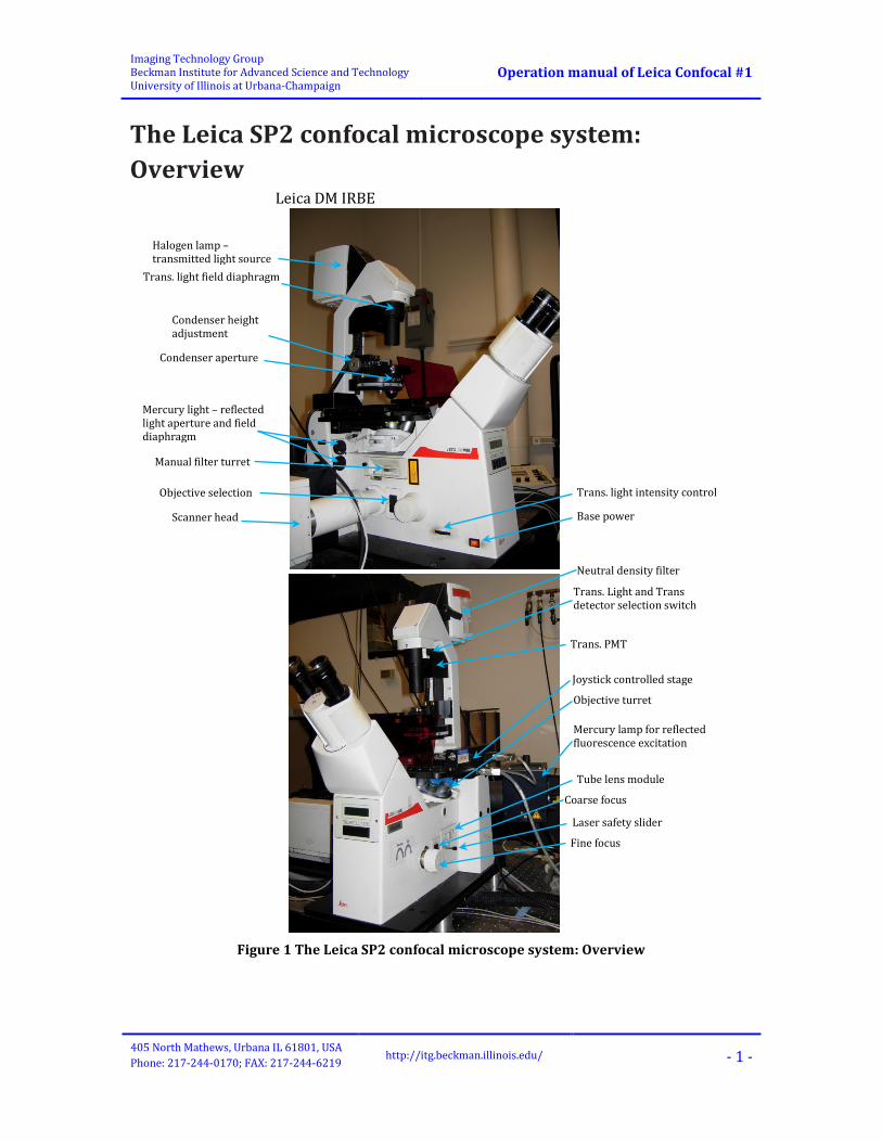
The Leica SP2 confocal microscope system: Overview
Figure 1 The Leica SP2 confocal microscope system: Overview
Leica DM IRBE
Halogen lamp – transmitted light source
Trans. light field diaphragm
Condenser height adjustment
Mercury light – reflected light aperture and field diaphragm
Scanner head
Trans. light intensity control
Base power
Condenser aperture
Objective selection
Manual filter turret
Neutral density filter
Trans. Light and Trans detector selection switch
Trans. PMT
Joystick controlled stage
Objective turret
Laser safety slider
Coarse focus
Fine focus
Tube lens module
Mercury lamp for reflected fluorescence excitation
Imaging Technology Group Beckman Institute for Advanced Science and Technology University of Illinois at Urbana-Champaign
Operation manual of Leica Confocal #1
405 North Mathews, Urbana IL 61801, USA Phone: 217-244-0170; FAX: 217-244-6219
http://itg.beckman.illinois.edu/ - 2 -
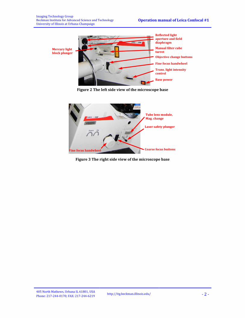
Figure 2 The left side view of the microscope base
Figure 3 The right side view of the microscope base
Tube lens module, Mag. change
Laser safety plunger
Coarse focus buttons Fine focus handwheel
Reflected light aperture and field diaphragm
Manual filter cube turret
Fine focus handwheel
Objective change buttons
Trans. light intensity control
Base power
Mercury light block plunger

Imaging Technology Group Beckman Institute for Advanced Science and Technology University of Illinois at Urbana-Champaign
Operation manual of Leica Confocal #1
405 North Mathews, Urbana IL 61801, USA Phone: 217-244-0170; FAX: 217-244-6219
http://itg.beckman.illinois.edu/ - 3 -
Start up the microscope system 1. Turn ON the scanner switch on the console. The scanner must warm up for 2 minutes
prior to starting the Leica LCS software. This will also turn ON the green (543-nm) and red (633-nm) helium/neon lasers. Note: you do not need to turn the keys labeled HeNe to start these lasers. These keys are generally left in the ON position.
2. Turn ON the red rocker switch labeled Ar/ArKr on the left-hand side of the console. This starts the cooling fan for the Ar Laser. Turn the left “Level Ar/ArKr” to the “MIN” position and
then turn the “Ar/ArKr” key above the switch to start the laser. The switch works just like a car ignition; turn the switch to the start position and then release it to the on position. At this point, the three orange lights at the top of the panel should be on, and the three rocker switches should also be lit up.
3. After 1 minute adjust the laser power dial to the tape arrow. This may already be set. For best stability, the laser will need to warm up for 15-20 minutes.
4. If you will use epifluorescence microscopy, turn ON the mercury lamp using the rocker switch on the small box on the ground under the computer table.
Console
Always left them on
Ar/ArKr laser cooling power; be aware of the note below it.
Scanner and Laser HeNe power
Ar/ArKr laser power key

Imaging Technology Group Beckman Institute for Advanced Science and Technology University of Illinois at Urbana-Champaign
Operation manual of Leica Confocal #1
405 North Mathews, Urbana IL 61801, USA Phone: 217-244-0170; FAX: 217-244-6219
http://itg.beckman.illinois.edu/ - 4 -
5. If you need the UV laser, turn on the water switch on the wall. Check the flow rate meter on the wall, and make sure it indicates a rate of ~8.4 l/min (2.2 gal/min). Locate the UV laser control console (see Figure 4) on the optical table. On this console, you should see no any red light on or flashing and then turn on the key switch. The PLASMA ON indicator will glow and emission will occur after about 15 seconds. When the laser emits, turn the left “current” knob to set the current to around 40 AMPS. Please don’t adjust change other settings on this console panel.
6. Turn ON the power to the microscope stand with the outside rocker switch located at the base of the large box on the right side of the microscope.
7. Log on to the computer. Your session will automatically be logged and databased through ITG’s logging software.
8. Launch the LCS program with the icon on the desktop; select the “Personal” software profile and press “start”. The below LCS program interface will appear. Do NEVER close the black “Leica Confocal Software” window. Select “Yes” on the “LCS” message window to enable protecting microscope condenser by limiting stage working area.
Figure 4 Stabilite UV laser control console
Adjust UV laser power by changing the laser current only.

Imaging Technology Group Beckman Institute for Advanced Science and Technology University of Illinois at Urbana-Champaign
Operation manual of Leica Confocal #1
405 North Mathews, Urbana IL 61801, USA Phone: 217-244-0170; FAX: 217-244-6219
http://itg.beckman.illinois.edu/ - 5 -
Setup microscope for imaging
Things to know before imaging 1. Check the objectives. The 10x and 20x objectives are DRY objectives, and should NEVER
have oil on them! 2. The 63× objective has aperture collar adjustment rings that control the size of aperture
opening. It should be wide open for most imaging condition. If your sample looks dim or the whole view field is not illuminated evenly when you look through the eyepieces, turn the collar to open the aperture.
3. The field diaphragm and aperture diaphragm (Figure 2 at page 2) in the excitation path of the mercury lamp are controlled by round, black dials on the left side toward the back of the microscope, and control the fluorescence illumination from the mercury lamp. For all imaging with the mercury light source, these should be set wide open by turning all the way counter-clockwise. The diaphragms are not used for laser confocal imaging.

Imaging Technology Group Beckman Institute for Advanced Science and Technology University of Illinois at Urbana-Champaign
Operation manual of Leica Confocal #1
405 North Mathews, Urbana IL 61801, USA Phone: 217-244-0170; FAX: 217-244-6219
http://itg.beckman.illinois.edu/ - 6 -
Reflected excitation light fluorescence viewing The setup procedure of reflected excitation light fluorescence viewing is as follows:
1. The switch for the mercury arc is on the power supply box sitting on the ground under the computer table. It should be turned on.
2. For fluorescence, turn OFF the transmitted light by turning the black dial (Figure 2 at page 2) away from you on the left-bottom of the microscope base. Turn away from you until the display panel (see the below graph) on front of the microscope reads 0*V.
3. The plunger on the right side of the microscope (safety shutter, see Figure 2 at page 2) should be pushed in.
4. The lower silver dial on the left side of the microscope (filter cube turret, see Figure 3 at page 2) controls filters and dichroic mirrors.
Choose proper filter set from position 1, 2 or 3: “1”→ for dual-band blue/green excitation (FITC and Texas Red). “2”→ for green excitation (TRITC, Rhodamine). “3”→ for UV excitation (DAPI, Hoechst) “4”→ for Laser, or Transmitted Light
5. Plunger on the left side (fluorescence shutter) should be pulled out to the first detent to send excitation light up through the objective. Now you should see excitation light coming from the lens, and you should be able to view focus through the oculars.
Imaging Technology Group Beckman Institute for Advanced Science and Technology University of Illinois at Urbana-Champaign
Operation manual of Leica Confocal #1
405 North Mathews, Urbana IL 61801, USA Phone: 217-244-0170; FAX: 217-244-6219
http://itg.beckman.illinois.edu/ - 7 -
Transmitted light bright field viewing
Setting up the microscope 1. Using the Fluorescent filter cube changer keys, choose the position marked with the
number ‘4’ (Laser or Transmitted light). 2. The plunger on the right side of the microscope (safety shutter, see Figure 2 at page
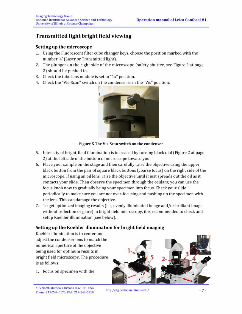
2) should be pushed in. 3. Check the tube lens module is set to “1x” position. 4. Check the “Vis-Scan” switch on the condenser is in the “Vis” position.
Figure 5 The Vis-Scan switch on the condenser
5. Intensity of bright-field illumination is increased by turning black dial (Figure 2 at page 2) at the left side of the bottom of microscope toward you.
6. Place your sample on the stage and then carefully raise the objective using the upper black button from the pair of square black buttons (coarse focus) on the right side of the microscope. If using an oil lens, raise the objective until it just spreads out the oil as it contacts your slide. Then observe the specimen through the oculars; you can use the focus knob now to gradually bring your specimen into focus. Check your slide periodically to make sure you are not over-focusing and pushing up the specimen with the lens. This can damage the objective.
7. To get optimized imaging results (i.e., evenly illuminated image and/or brilliant image without reflection or glare) in bright field microscopy, it is recommended to check and setup Koehler illumination (see below).
Setting up the Koehler illumination for bright field imaging Koehler illumination is to center and adjust the condenser lens to match the numerical aperture of the objective being used for optimum results in bright field microscopy. The procedure is as follows:
1. Focus on specimen with the

Imaging Technology Group Beckman Institute for Advanced Science and Technology University of Illinois at Urbana-Champaign
Operation manual of Leica Confocal #1
405 North Mathews, Urbana IL 61801, USA Phone: 217-244-0170; FAX: 217-244-6219
http://itg.beckman.illinois.edu/ - 8 -
objective to be used. 2. Partly close down lamp field stop [diaphragm at top (1)] while viewing. 3. Lower condenser slightly (2) until diaphragm image is in focus. 4. Center image using condenser centering screws (3). 5. Open diaphragm (1) to edge of field, fine focus and open further to just clear field. 6. Adjust contrast using condenser diaphragm (4). 7. Insert Bertrand Lens (5) and check to see that 75%-90% of visible aperture is filled with
light (more light = better resolution but less contrast).
Benefits from Koehler illumination: 1) evenly illuminated image. 2) Brilliant image without reflection or glare. 3) Minimum heating of specimen.
Other transmitted light parts Almost always, the condenser needed for transmitted light imaging is sitting next to the microscope. There is a mark on the micro- scope indicating the proper height for the condenser. Use a 3mm Allen screw driver to snug it into place. Please do not over tighten. Leica confocal 2 is installed with the S23 condenser. A higher numerical aperture condenser is used in the Leica SP2 confocal-1.
Imaging Technology Group Beckman Institute for Advanced Science and Technology University of Illinois at Urbana-Champaign
Operation manual of Leica Confocal #1
405 North Mathews, Urbana IL 61801, USA Phone: 217-244-0170; FAX: 217-244-6219
http://itg.beckman.illinois.edu/ - 9 -
Confocal imaging Ensure that the transmitted light illumination column is pulled forward to its normal upright position – this is the laser safety switch.
Basic settings of confocal scanning with Leica confocal #2 • If widefield fluorescence illumination has been used, push the plunger on the left side of the microscope (see Figure 2 at page 2) in to block extraneous light from the mercury arc excitation source.
• Turn the silver dial, left side (filter cube turret, see Figure 2 at page 2), to the “4” position.
• You may turn the silver dial, right side, lower level (compensating lens, see Figure 3 at page 2), towards you to the “1.5X” or “1X” position, which will change the image magnification.
• Pull the plunger on the right side of the microscope (safety shutter, see Figure 3 at page 2) out.
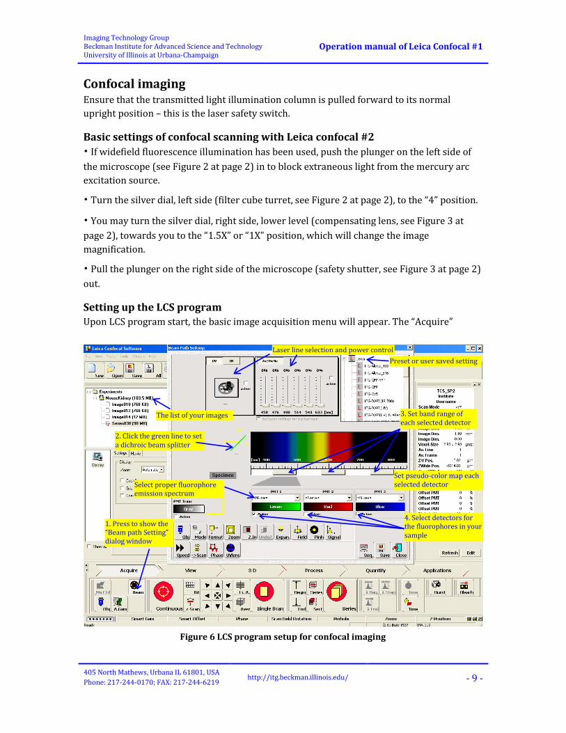
Setting up the LCS program Upon LCS program start, the basic image acquisition menu will appear. The “Acquire”
Figure 6 LCS program setup for confocal imaging
The list of your images
Laser line selection and power control
2. Click the green line to set a dichroic beam splitter
4. Select detectors for the fluorophores in your sample
3. Set band range of each selected detector
Set pseudo-color map each selected detector
1. Press to show the “Beam path Setting” dialog window
Select proper fluorophore emission spectrum
Preset or user saved setting

Imaging Technology Group Beckman Institute for Advanced Science and Technology University of Illinois at Urbana-Champaign
Operation manual of Leica Confocal #1
405 North Mathews, Urbana IL 61801, USA Phone: 217-244-0170; FAX: 217-244-6219
http://itg.beckman.illinois.edu/ - 10 -
button should appear pressed.
Some basic default settings of LCS program are summarized as follows:
Name Default setting Mode xyz Format 512*512 Zoom 1 Speed 400Hz
Initial LCS program settings for confocal imaging by following the below procedure:
1. Click “Beam” button (see Figure 7). In the “Beam path setting” dialog, 1) select a proper dichroic beamsplitter; 2) activate the proper detector (PMTs) and 3) set up the emission detector bandwidth for the fluorophores in your sample. If you need to use the “PMT Tran” detector, the Vis-Scan switch (see Figure 5 at page 7) must be set to the “Scan” position.
Note: You also can change the color scheme of individual images into any color or grey by clicking the pseudo-color box associated with PMTs on the window screen (Note: the color information will be saved with image files when saved).
4) You can also simply activate the laser lines and adjust the laser power level, but it always is highly recommended that you start to increase the laser power when you start continuous imaging (see the below section – Continuous imaging).
2. Select Mode (Default: xyz)
XYZ is the system default. Time series and Wavelength (Lambda) scan options are also available.
3. Select Format (Default: 512*512)
Click in the ‘Format’ panel and select the image x- and y-dimension in pixel.
Note: Zoom changes automatically when you change scan Speed!

Imaging Technology Group Beckman Institute for Advanced Science and Technology University of Illinois at Urbana-Champaign
Operation manual of Leica Confocal #1
405 North Mathews, Urbana IL 61801, USA Phone: 217-244-0170; FAX: 217-244-6219
http://itg.beckman.illinois.edu/ - 11 -
4. Check Zoom
As a general rule, it is good to have at least two sampling intervals (pixels) per resolvable unit. To achieve this, the table below may be of use.
Objective Zoom Format 63× ×3 1024×1024 63× ×6 512×512 40× ×6 1024×1024 40× ×10 512×512 20× ×8 1024×1024 20× ×10 512×512
Keep in mind that increasing zoom will magnify the image but also will bleach the sample faster!
5. Check Beam Expander
In most cases the standard setting “Beam Exp 6” is best. However, in experiments in which weak lasers and high-resolution objectives are used, setting the beam expander to a smaller value can improve the illumination of the objective lens.
6. Check Field Rotation
Select Field button to adjust field rotation. — Remember to set Field Rotation back to Zero (0) before logging out of software. If you forget to do this the scanhead may not initialize correctly for the next user.
7. Set Pinhole (1 Airy Unit – Airy Disc by default)
Check the pinhole size on the panel describing confocal settings. If necessary, change pinhole size to 1 Airy Disc (traditional setting used for confocal imaging). The ‘Pinhole’ button will give you the information about the absolute value of the pinhole.
8. Set Speed (the default frequency is 400Hz).
This means that the system will scan 400 lines in one second. Using a lower scan speed you get better signal- to-noise ratio (at the cost of potentially increasing photobleaching).
9. Set Scan direction
For “Scan” most people use the default (unidirectional scan). Bi-directional scan doubles the scan speed; however, recording images in bidirectional scan mode can result in a phase shift between the forward sweep and flyback of the scanning beam. To address this problem when using bi-directional scanning mode, you should click the “Phase” button to open a dialog window, which you can use to correct the shift.
10. Set z-Scan (Default: z-Galvo)

Imaging Technology Group Beckman Institute for Advanced Science and Technology University of Illinois at Urbana-Champaign
Operation manual of Leica Confocal #1
405 North Mathews, Urbana IL 61801, USA Phone: 217-244-0170; FAX: 217-244-6219
http://itg.beckman.illinois.edu/ - 12 -
To use the stage focus motor to acquire Spatial Image Series instead of Z-Galvo just select z-Wide (button next to Continuous) and then select “Z Wide Position” for focus control knob. This will change the default range of movement from 166.68 microns to 8085.01 microns and allow control of Z-depth with remote focus knob, instead of the fine focus on the microscope base.
Continuous imaging 1. Select an objective by click on the blue “Obj” button, and find the image in the objective
focal plane by using the “Reflected excitation light fluorescence viewing” or “Transmitted light bright field viewing” (See the previous chapters.)
2. Check the Basic settings of confocal scanning with Leica confocal #2 at page 9. 3. Click the red ‘Continuous’ scan button to start the scan; an image or images, depending
on the number of active detectors, will appear on the right monitor. 4. Left-click the mouse over the image channel on the “Experiment” window to select it;

Imaging Technology Group Beckman Institute for Advanced Science and Technology University of Illinois at Urbana-Champaign
Operation manual of Leica Confocal #1
405 North Mathews, Urbana IL 61801, USA Phone: 217-244-0170; FAX: 217-244-6219
http://itg.beckman.illinois.edu/ - 13 -
the selected image panel will be highlighted with a white dash line square box (see the above graph) and follow the below steps to get qualified image: 1) Make sure that the laser line to be used for the selected image channel is set to
“active” at the lowest intensity position (0%). 2) Adjust the PMT “Smart Gain” (the first knob on panel box from left, see Figure 8) to
highest possible (NOTE: don’t overload the PMT; you may be warned by “beeps” when you reach the maximum gain).
3) Gradually increase the laser intensity by dragging the laser power bar until an image appears on the image panel. Or if the image signal is still too weak when the maximum laser intensity (100%) is reached, slightly adjust the focus by using the ‘Focus’ control (the last dial on the panel box, see Figure 8); turn it clockwise and/or counter-clockwise until a good quality image is found (Hint: the objective focal plane found using eyepiece can be slightly different from that in confocal scanning).
4) Balance the PMT gain and the laser intensity. High PMT gain generates high background noise; high laser intensity can cause the sample fast photobleaching and both can result in saturation at the brightest pixels of the image (see the below note to know how to find saturation pixels in an image). Try to obtain good quality images at lower PMT gain and laser intensity. Note: Use Q-LUT to set Over/Under (adjust dynamic range of PMT ) The special ‘Glow Over/Under’ type of pseudocolor provided by pressing the ‘Q LUT’ button next to the active image is useful to adjust the brightness so that the maximum dynamic range of the PMT is made available. In this color scheme, pixels which are saturating the PMT are colored blue and pixels which have a value of 0 are colored green. The idea is to set the PMT gain so that the brightest pixels are just slightly under being saturated and the offset such that the darkest pixels are just above a value of zero.
5) After the above step 4), the image background can be further decreased by adjusting the “Smart Offset” (the second knob on panel box from left, see Figure 8). Turn the Offset knob while observing the image to achieve best signal-to-noise.
5. Repeat the above step (#3) for all image channels. 6. Stop continuous scanning by re-clicking on the ‘Continuous’ button. Now you may
change the color of the image to the appropriate hue (green, blue or red) after you adjusted everything. This can be done by selecting the color listing associated with a particular PMT. However, it is often useful to image everything in “Q-LUT” mode, watching for saturation. Also, monochromatic images, especially those colored blue, will often appear dark to the human eye. This can be remedied through the use of contrast
Figure 7 The control panel in front of the monitor

Imaging Technology Group Beckman Institute for Advanced Science and Technology University of Illinois at Urbana-Champaign
Operation manual of Leica Confocal #1
405 North Mathews, Urbana IL 61801, USA Phone: 217-244-0170; FAX: 217-244-6219
http://itg.beckman.illinois.edu/ - 14 -
expansion algorithms in postprocessing of the images. You may change the colors later, after imaging using the ‘Leica LCS Lite’ software.
Save global confocal configuration After you have done all above settings for LCS program, i.e., adjusted the image brightness, pinhole, zoom, etc., and you are satisfied with the quality of image, use the ‘Save’ button on the window with the detector settings if you wish to save your global confocal configuration. Your settings can be loaded from the User area (Highlighted as “Preset or user saved setting” in Figure 7 at page 9) of the Beam Path Settings window.
Acquire a single image 1. Choose line averaging
Image averaging is a method used to improve the signal-to-noise ratio of an image. To use image averaging, first click either “Aver” (average by frame) or “Li. A.” (Average by line) button and select the number of images to be averaged. This will reduce the apparent noise in each image. Averaging by line permits averaging during a continuous scan; averaging by frame permits the automatic switching of settings between channels during a sequential scan (see the Leica LCS documentation for more in depth information).
2. Scan image Use the red ‘Single Scan’ button to obtain single image.
Save data Remember to often save your data. There are two locations for saving your data:
1. Save to remote network share folder at zeus.itg.uiuc.edu (or Z disk by default in “My computer”);
2. Save to the local disk labeled “Workspace” (D: or E:\Workspace\”username”). A folder was created automatically at the first time login for each user. This is a useful option if the network is down.
The saved images can be viewed in other programs (Adobe Photoshop, Fiji, ImageJ, Imaris, Image, Pro Plus, etc.).
Acquire volumetric datasets (Z-Series) It is assumed that the steps in the sections of “Setting up” and “Continuous imaging” for confocal imaging have been completed before acquiring z-series images.
1. Click on the red “Continuous” button to start continuous imaging. 2. Click on the small “Series” button (see the below left graph; the big one will be used
later) to define the top and bottom of the volume of interest, both of which are identified interactively using the ‘Focus’ control (the 6th dial on the panel box). The “Setting Z/Y-Position for Spatial Image Series” window will pop up. Turn this clockwise and then counter-clockwise until you find the top and bottom of your region of interest.

Imaging Technology Group Beckman Institute for Advanced Science and Technology University of Illinois at Urbana-Champaign
Operation manual of Leica Confocal #1
405 North Mathews, Urbana IL 61801, USA Phone: 217-244-0170; FAX: 217-244-6219
http://itg.beckman.illinois.edu/ - 15 -
3. Set Begin Point
Move to the top of your sample by turning the ‘Focus’ control (the last dial on the panel box, see Figure 8 at page 13) clockwise. Click on the “Begin” button (it should turn white). This marks the beginning of your 3D image.
4. Set End point Turn the ‘Focus’ control counter-clockwise until you find the bottom end of your region of interest. Then click on the “End” button (it should turn white as well). This marks the end of your 3D volume.
5. Close the “Setting Z/Y-Position for Spatial Image Series” window and stop Continuous imaging.
6. Check the thickness of each optical section. Select the ‘Sect’ button, and choose the desired number of focal planes. If you click instead on “Others”, you may enter the focal plane spacing, and then the program will calculate the number of focal planes required to cover the distance between your endpoints marked by “Begin” and “End”. By default the software determines the number of sections which will yield the maximum optical z-resolution for an ideal sample.
7. Click on “Aver” or “Li. A.” button to set the number of averaging per frame. 8. Start z-series scan imaging – click on large ‘Series’ button (see the left-bottom image on
the previous page). The Gall. Button (Gallery display mode) on the “Experiment” Window can be selected to view series progress.
Sequential scanning (temporal separation of lasers) Sequential scanning is a method used to decrease the cross-talk of signal readings from multiple probes with overlapping emission spectra. In sequential scanning, the images of the individual channels are acquired separately, i.e., first with one excitation wavelength, then with the other.
It is assumed that the steps in the sections of “Setting up” and “Continuous imaging” for confocal imaging have been practiced or completed before acquiring sequential scanning

Imaging Technology Group Beckman Institute for Advanced Science and Technology University of Illinois at Urbana-Champaign
Operation manual of Leica Confocal #1
405 North Mathews, Urbana IL 61801, USA Phone: 217-244-0170; FAX: 217-244-6219
http://itg.beckman.illinois.edu/ - 16 -
images.
1. To set up a sequential scan you have to set all parameters for each fluorophore of your sample – Set up a condition by only activating and adjusting laser level and PMT settings for one fluorophore, and save the global configuration setting for this fluorophore (see the section “Save global confocal configuration” at page 14). Repeat the same process for the other fluorophores.
2. In the “Beam Path Setting” dialog window, click on the button labeled “Seq.” in the bottom left corner. Add the fluorophore acquisition setting one at a time by selecting them in the beam window and then click “Add” button in the “Sequential scan settings” window. Check the parameters shown in the ‘Parameter’ list box. In the ‘Mode’ list box, select one of the three sequential scan modes. This selection defines when the sequential recording methods are alternated; the ‘between lines’ option can only be used if the detector ranges do not change in between every two instrument parameter settings used in the sequential scan. Note: the ‘between lines’ mode is also the only mode which can be used for a continuous scan. You can save these sequential acquisition settings by clicking the “Save” button. Do not close the settings window.
3. Start the acquisition by clicking “Single Scan” or “Series” button depending on your imaging condition.
Simple time-lapse series Time series allows time-lapse imaging of live samples to study the changes and dynamics of your object of interest.
It is assumed that the steps in the sections of “Setting up” and “Continuous imaging” for confocal imaging have been practiced or completed before acquiring time-lapse Series images.
1. Click on “Seq.” to show the “Sequential scan settings” window
2. Select the preset setting of the fluorophore
3. Click “Add” to add the selected setting
Imaging Technology Group Beckman Institute for Advanced Science and Technology University of Illinois at Urbana-Champaign
Operation manual of Leica Confocal #1
405 North Mathews, Urbana IL 61801, USA Phone: 217-244-0170; FAX: 217-244-6219
http://itg.beckman.illinois.edu/ - 17 -
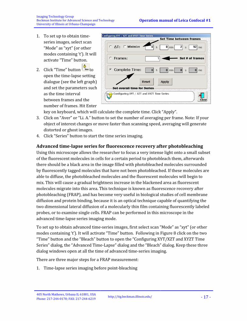
1. To set up to obtain time-series images, select scan “Mode” as “xyt” (or other modes containing ‘t’). It will activate “Time” button.
2. Click “Time” button to open the time-lapse setting dialogue (see the left graph) and set the parameters such as the time interval between frames and the number of frames. Hit Enter key on keyboard, which will calculate the complete time. Click “Apply”.
3. Click on “Aver” or “Li. A.” button to set the number of averaging per frame. Note: If your object of interest changes or move faster than scanning speed, averaging will generate distorted or ghost images.
4. Click “Series” button to start the time series imaging.
Advanced time-lapse series for fluorescence recovery after photobleaching Using this microscope allows the researcher to focus a very intense light onto a small subset of the fluorescent molecules in cells for a certain period to photobleach them, afterwards there should be a black area in the image filled with photobleached molecules surrounded by fluorescently tagged molecules that have not been photobleached. If these molecules are able to diffuse, the photobleached molecules and the fluorescent molecules will begin to mix. This will cause a gradual brightness increase in the blackened area as fluorescent molecules migrate into this area. This technique is known as fluorescence recovery after photobleaching (FRAP), and has become very useful in biological studies of cell membrane diffusion and protein binding, because it is an optical technique capable of quantifying the two dimensional lateral diffusion of a molecularly thin film containing fluorescently labeled probes, or to examine single cells. FRAP can be performed in this microscope in the advanced time-lapse series imaging mode.
To set up to obtain advanced time-series images, first select scan “Mode” as “xyt” (or other modes containing ‘t’). It will activate “Time” button. Following in Figure 8 click on the two “Time” button and the “Bleach” button to open the “Configuring XYT/XZT and XYZT Time Series” dialog, the “Advanced Time-Lapse” dialog and the “Bleach” dialog. Keep these three dialog windows open at all the time of advanced time-series imaging.
There are three major steps for a FRAP measurement:
1. Time-lapse series imaging before point-bleaching

Imaging Technology Group Beckman Institute for Advanced Science and Technology University of Illinois at Urbana-Champaign
Operation manual of Leica Confocal #1
405 North Mathews, Urbana IL 61801, USA Phone: 217-244-0170; FAX: 217-244-6219
http://itg.beckman.illinois.edu/ - 18 -
Here it is
assumed that the steps in the sections of “Setting up” and “Continuous imaging” for confocal imaging have been completed and a region of interest (ROI) for imaging is selected (e.g., Figure 9). 1) Specify the laser intensity level in the “Beam Path Setting” dialog window if
necessary; 2) Configure the dialog “Configuring XYT/XZT and XYZT Time Series” dialog” – Fill the
“Frames” box with the total number of images required prior to the point photobleaching and press “Apply”, and then the “Complete Time” should be updated automatically.
3) Configure the dialog “Advanced Time-Lapse” – Press “Reset” first if any settings on this dialog have been done before. Set for the first imaging interval (Lapse 1):
a. Click on “define” button to store all current hardware settings for this imaging interval. To see what settings have been saved for this interval, click on “Recall” at any time.
b. Deactivate the “Bleach” and “Bleach Dialog” check box.
c. If necessary, in the first list box under “Continue”, set a pause period between processing the
Figure 9 Open three dialogs for advance time-lapse imaging
Figure 8 Image before photobleaching

Imaging Technology Group Beckman Institute for Advanced Science and Technology University of Illinois at Urbana-Champaign
Operation manual of Leica Confocal #1
405 North Mathews, Urbana IL 61801, USA Phone: 217-244-0170; FAX: 217-244-6219
http://itg.beckman.illinois.edu/ - 19 -
first and the following imaging interval. d. In the second list box under “Continue”, select “Lapse 2”.
2. Point-bleaching 1) Configure the dialog “Bleach” and define the bleach points (see Figure 11).
a. Click and select the dialog “Bleach”. b. Click and Select the bleach points in the image on the “Experiment” window,
and the selected points will appear in the list of “Bleach points” on the “Bleach” dialog.
c. Click on the “Select all” button to select all bleaching points. d. Set the bleaching time in the “Duration” field. e. Increase the laser intensity to desired level for bleaching in the “Beam Path
Setting” window and click the “Define” button in the “Bleach” dialog window. 3. Time-lapse series imaging after point-bleaching
1) Specify the laser intensity level in the “Beam Path Setting” dialog window if necessary. If you want to use exactly the same laser intensity settings for “Lapse 1”, click on the “Recall” button in the first time interval “Lapse 1”.
2) Configure the dialog “Configuring XYT/XZT and XYZT Time Series” dialog” – Fill the “Frames” box with the total number of images required after the point photobleaching and press “Apply”.
3) Configure the dialog “Advanced Time-Lapse” – Set for the last imaging interval (Lapse 2):
a. Click on “define” button to store all current hardware settings for this imaging interval.
b. Activate the “Bleach” check box; deactivate the “Bleach Dialog” check box, or otherwise activate it if you want to set up the bleach points when processing to this setup.
c. In the first list box under “Continue”, set to “0”. d. In the second list box under “Continue”, select “Finished”.
Now you can start the FRAP experiment by clicking on the “Start” button of the first imaging interval “Lapse 1” on the “Advanced Time-Lapse” dialog window. The imaging interval “Lapse 1” is performed first (prebleach), following with the bleaching process (point bleach
ROI 1
ROI 2
Figure 10
Imaging Technology Group Beckman Institute for Advanced Science and Technology University of Illinois at Urbana-Champaign
Operation manual of Leica Confocal #1
405 North Mathews, Urbana IL 61801, USA Phone: 217-244-0170; FAX: 217-244-6219
http://itg.beckman.illinois.edu/ - 20 -
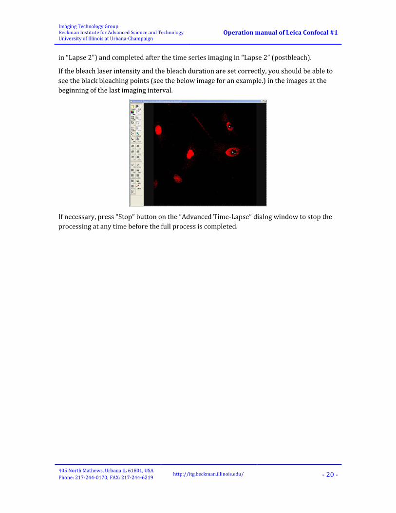
in “Lapse 2”) and completed after the time series imaging in “Lapse 2” (postbleach).
If the bleach laser intensity and the bleach duration are set correctly, you should be able to see the black bleaching points (see the below image for an example.) in the images at the beginning of the last imaging interval.
If necessary, press “Stop” button on the “Advanced Time-Lapse” dialog window to stop the processing at any time before the full process is completed.

Imaging Technology Group Beckman Institute for Advanced Science and Technology University of Illinois at Urbana-Champaign
Operation manual of Leica Confocal #1
405 North Mathews, Urbana IL 61801, USA Phone: 217-244-0170; FAX: 217-244-6219
http://itg.beckman.illinois.edu/ - 21 -
Shut down the microscope system Don’t forget to shut down the system after use. You can leave it on only in the case that you are sure the microscope must be used later either by yourself or by other users in the same day.
1. Clean any immersion oil from the objectives. 2. If the scan rotation feature was used, please remember to reset the scan rotation
through the software interface. If you forget to do this, the scanhead may not initialize
correctly for the next user. 3. Switch to the 10x objective, save your files and exit the LCS program. 4. Log off the computer − don’t forget to check the electronic logbook for accurate
recording of instrument usage time (notebook icon on desktop). 5. Turn off the microscope base and mercury lamp (under the computer table) with the
appropriate switches. 6. Turn the red Scanner switch on the console off. 7. Minimize the Ar/ArKr laser power and turn the Ar/ArKr laser key to the off position.
Console
Always left them on
Ar/ArKr laser cooling power; be aware of the note below it.
Scanner and Laser HeNe power
Ar/ArKr laser power key

Imaging Technology Group Beckman Institute for Advanced Science and Technology University of Illinois at Urbana-Champaign
Operation manual of Leica Confocal #1
405 North Mathews, Urbana IL 61801, USA Phone: 217-244-0170; FAX: 217-244-6219
http://itg.beckman.illinois.edu/ - 22 -
Wait for 5 minutes to allow the Argon laser to cool down to protect the laser from damage, and then turn off the argon cooling fan using the red rocker switch.
8. If you have used UV, turn off the key switch on the UV laser control console (see Figure 4 at page 4). Wait for at least 10 minutes to allow the laser to cool down to protect the laser from damage, and then turn off the cooling water switch on the wall.

Imaging Technology Group Beckman Institute for Advanced Science and Technology University of Illinois at Urbana-Champaign
Operation manual of Leica Confocal #1
405 North Mathews, Urbana IL 61801, USA Phone: 217-244-0170; FAX: 217-244-6219
http://itg.beckman.illinois.edu/ - 23 -
Troubleshooting
1. Occasionally a buzz can be heard emanating from the stage transducer box, this is probably because the stage is not reliably returning to the begin and end set positions. Try to turn the “Focus” dial on the panel box (see Figure 8) counter-clockwise all the way to left.
2. No mercury lamp light for reflected fluorescence viewing even after the lamp is powered on. This is probably because the lamp was just powered off by last user and the mercury lamp requires 20-30 minutes to cool down before it can be turned on again. Therefore, power it off and wait for 30 minutes.
In case of any other suspected technical problems with the microscope, please do NEVER try “Do-It-Yourself” repairs or alignment of the microscope. Contact with our ITG staff for technical assistance.
Imaging Technology Group Beckman Institute for Advanced Science and Technology University of Illinois at Urbana-Champaign
Operation manual of Leica Confocal #1
405 North Mathews, Urbana IL 61801, USA Phone: 217-244-0170; FAX: 217-244-6219
http://itg.beckman.illinois.edu/ - 24 -
Appendix
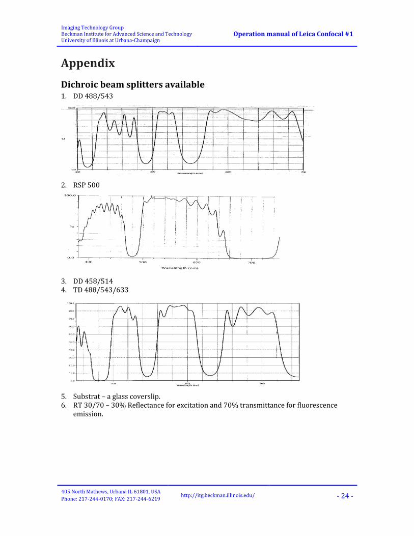
Dichroic beam splitters available 1. DD 488/543
2. RSP 500
3. DD 458/514 4. TD 488/543/633
5. Substrat – a glass coverslip. 6. RT 30/70 – 30% Reflectance for excitation and 70% transmittance for fluorescence
emission.

Imaging Technology Group Beckman Institute for Advanced Science and Technology University of Illinois at Urbana-Champaign
Operation manual of Leica Confocal #1
405 North Mathews, Urbana IL 61801, USA Phone: 217-244-0170; FAX: 217-244-6219
http://itg.beckman.illinois.edu/ - 25 -
Objectives available
Objective 10× HC PL FLUOTAR
20× HCX PLAN APO
40× HCX PL APO CS
63× PL FLUOTAR
63x HCX PL APO CS
63× HCX PL APO CS
Immersion Air Air Oil Air Water Oil N.A. 0.3 0.7 1.25 0.7 1.2 1.4-0.6
Free working distance (mm) 11.0 0.59 0.1 2.6-1.8 0.07 0.1
Coverslip thickness (mm)
With or without
coverglass 0.17 0.17 0.10-1.3 0.14-0.18 0.17
Phase ring PH1 PH2 PH3 PH2 − − DIC S1
Condenser K2 K2 K5 K5 K5 K4
DIC Obj Prism D1 C E C D E Resolution XY
(488nm) 650.7 nm 278.9 nm 156.2 nm 278.9 nm 162.7 nm 139.4 nm
Resolution Z (488nm)
4767.6 nm 768.2 nm 334.4 nm 768.2 nm 290.3 nm 235.8 nm
Part # 506507 506170 506181 506062 506212 506188 Optimized for
confocal scanning
No No Yes No Yes Yes
Note Damaged Tube length ∞, reference focal length of tube lens fB = 200 mm, parfocalizing distance 45 mm. All objectives are M25 thread. DIC Obj Prism: B2 / D wide shearing = higher contrast B1 / D1 narrow shearing = higher resolution Abbreviations: Air = No immersion media-coverslip/mountant required for optimal resolution Oil = DIN/ISO standard immersion oil with reflective index = 1.51 DIC = Differential Interference Phase Contrast

Imaging Technology Group Beckman Institute for Advanced Science and Technology University of Illinois at Urbana-Champaign
Operation manual of Leica Confocal #1
405 North Mathews, Urbana IL 61801, USA Phone: 217-244-0170; FAX: 217-244-6219
http://itg.beckman.illinois.edu/ - 26 -
Condensers available 1. S1 (DIC & Phase & BF), N.A. = 0.90
Located on Confocal #1 Objective range: 10×-100× Condenser prisms: K2-K5+K11 only with condenser top 0.90 S1 Objective prisms: A-E Prisms D wide shearing = higher contrast
2. S23 (Phase & BF), N.A. = 0.53
Located on Confocal #2 PH0, PH1, PH2, PH3 Objective range: 5×-100×
Imaging Technology Group Beckman Institute for Advanced Science and Technology University of Illinois at Urbana-Champaign
Operation manual of Leica Confocal #1
405 North Mathews, Urbana IL 61801, USA Phone: 217-244-0170; FAX: 217-244-6219
http://itg.beckman.illinois.edu/ - 27 -
References
Calibration Standards Calibration Grid Slide from Micro Brightfield: http://www.mbfbioscience.com
Fluorescent Reference Slides from Microscopy Education: http://www.microscopyeducation.com
Leica SP2 Leica Microsystems Inc.
2345 Wuakegan Road, Bannockburn IL 60015
web: http://www.leica-microsystmes.com
Commercial anti-fade mounting media • ProLong Gold Antifade Mountant: http://www.invitrogen.co.jp/products/pdf/mp36930.pdf
• Vectashield Antifade Mounting Medium: http://www.vectorlabs.com/VECTASHIELD/VECTASHIELD.html
• VECTASHIELD HardSet Mounting Medium: http://www.vectorlabs.com/products.details.asp?prodID=1483
Fluorescence Microscopy Books/Papers Allan, V., Ed., Protein Localization by Fluorescence Microscopy: A Practical Approach, Oxford Uni- versity Press (1999).
Andreeff, M. and Pinkel, D., Eds., Introduction to Fluorescence In Situ Hybridization: Principles and Clinical Applications, John Wiley and Sons (1999).
Herman, B., Fluorescence Microscopy, Second Edition, BIOS Scientific Publishers (1998).
Michalet, X., Kapanidis, A.N., Laurence, T., Pinaud, F., Doose, S., Pflughoefft, M. and Weiss S., “The power and prospects of fluorescence microscopies and spectroscopies,” Annu Rev Biophys Biomolec Struct 32, 161–182 (2003).
Murphy, D.B., Fundamentals of Light Microscopy and Electronic Imaging, John Wiley and Sons, (2001). Molecular Probes.
Spector, D.L. and Goldman, R.D., Basic Methods in Microscopy, Cold Spring Harbor Laboratory Press (2005).
Yuste, R. and Konnerth, A., Eds., Imaging in Neuroscience and Development: A Laboratory Manual, Cold Spring Harbor Laboratory Press (2004).


