Leica TCS SL Confocal Training - Ohio State...
68
Leica TCS SL Confocal Training Neuroscience Imaging Facility The Ohio State University Rightmire Hall 292-3025 Neuroscience Imaging Core Staff Core Director Anthony Brown, Ph. D. 060 Rightmire Hall 292-1205 [email protected] Facility Manager Paula Monsma 062 Rightmire Hall 292-3025 [email protected]
Transcript of Leica TCS SL Confocal Training - Ohio State...

Leica TCS SL Confocal Training
Neuroscience Imaging Facility The Ohio State University Rightmire Hall 292-3025
Neuroscience Imaging Core Staff
Core Director
Anthony Brown, Ph. D. 060 Rightmire Hall 292-1205 [email protected]
Facility Manager
Paula Monsma 062 Rightmire Hall 292-3025 [email protected]

CMN Imaging Core 1/16/2013
2
Leica TCS SL Confocal Training ......................................................... 1 Neuroscience Imaging Core Staff ....................................................... 1
Core Director ................................................................................... 1 Facility Manager .............................................................................. 1
Access ................................................................................................. 4 Access to the room.......................................................................... 4 Scheduling time ............................................................................... 4 Contact numbers ............................................................................. 5
What is fluorescence? ......................................................................... 6 How does a fluorescence microscope work? ...................................... 6 The principal behind confocal microscopy: ......................................... 7 How does a confocal microscope work? ............................................. 7 Why use Confocal Imaging .................................................................. 8 The Microscope ................................................................................... 9 Z-Galvo stage ...................................................................................... 9 Why use an inverted microscope? .................................................... 10
Benefits ......................................................................................... 10 Cautions ........................................................................................ 10
Specimen Mounting ........................................................................... 10 Fixed Specimen............................................................................. 10 Living Specimen ............................................................................ 10
Objectives .......................................................................................... 11 Understanding Objectives ................................................................. 11 Care of Objectives ............................................................................. 13 Epifluorescence Filter Cubes ............................................................. 13 Phase and DIC .................................................................................. 14 The Confocal Microscope and Workstation Layout ........................... 15 AOTF ................................................................................................. 16 Spectral Detectors ............................................................................. 16 Crosstalk ............................................................................................ 18 Getting Started .................................................................................. 19 Start the Leica Confocal Software ..................................................... 19 Left Monitor ........................................................................................ 20 Information Window ........................................................................... 21 Beam Path Setting Window ............................................................... 23 Format Button .................................................................................... 24 Mode Button ...................................................................................... 24 Obj button .......................................................................................... 25 MicCtrl Button .................................................................................... 25 Pinh Button ........................................................................................ 26 Speed Button ..................................................................................... 26 Right Monitor ..................................................................................... 27 Viewer Toolbar................................................................................... 28
CMN Imaging Core 1/16/2013
3
Collecting an image ........................................................................... 29 The Beam Path Settings Window ................................................. 30 Take the first image ....................................................................... 30 Create an overlay of the two channels .......................................... 31 Optimize the gain and offset of the two channels ......................... 32
Averaging ........................................................................................... 33 Crosstalk ............................................................................................ 34
Check for Crosstalk ....................................................................... 34 Check for crosstalk from the other laser line ................................. 35 Adjust beam path settings for crosstalk ........................................ 36 Change the detection slot ............................................................. 37
Set up a sequential scan ................................................................... 39 Optimize the settings for each channel ......................................... 39 Save the sequential setting ........................................................... 40 Load the sequential scan settings ................................................. 41 Acquire an image using the sequential scan settings ................... 43
Zoom Functions ................................................................................. 44 Zooming on a specific area ........................................................... 44 Centered Zoom ............................................................................. 45
DIC ..................................................................................................... 46 Saving the Data ................................................................................. 47
Saving the experiment .................................................................. 47 Saving the overlay image .............................................................. 49
Experiments ....................................................................................... 50 Create a new experiment .............................................................. 50 Open a saved experiment ............................................................. 51 Renaming images ......................................................................... 52 Browsing all the images in an experiment .................................... 52
Adding a scale bar ............................................................................. 53 Taking a Z series ............................................................................... 55
Set the Start and End Points ......................................................... 55 Set the number of sections ........................................................... 56 Collect the series ........................................................................... 57 Viewing the Z-series ...................................................................... 58
Create a 3D Projection and Animation .............................................. 59 Select the Projection Type ............................................................ 60 Preview the Projection .................................................................. 60
Export an Animation .......................................................................... 62 Archiving Data - Create a data disk ................................................... 63 Logging off of the computer ............................................................... 67 Shutting Down ................................................................................... 68 Alternate Shut Down Procedure: ....................................................... 68

CMN Imaging Core 1/16/2013
4
Access
Access to the Confocal Microscope
Supervised Unsupervised
Mon-Fri 9a-5p
Mon-Fri 9a-5p
Evenings and Weekends
Required Experience
Trainee
X
Seminar & minimum of 2
supervised sessions.
Advancement decided on case
by case basis Standard user
X
X
Seminar & minimum of 10 unsupervised
sessions. Advancement
decided on case by case basis
Experienced user
X
X
X
Advancement decided on case
by case basis
Access to the room
–Pick up the key in room 135
Scheduling time
–Sign up on the door for use of the confocal microscope, as well as the offline workstation or contact Paula with time and date request

CMN Imaging Core 1/16/2013
5
Contact numbers
Question about how to use the microscope, i.e. software questions –Contact Paula 292-3025 9a-5p, M-F –Leica OneCall 866-830-0735 9a-5p, M-F
Physical problem with microscope, i.e., it’s broken –Contact Paula 292-3025 9a-5p, M-F
Problem after hours
–Contact Paula 270-3239
Computers
Two workstations –Online -for imaging (Leica Confocal) –Offline -for analyzing data (Leica Offline) Windows XP operating system protected by a firewall Data storage –Send to your computer over the network –Archive to an external hard drive using firewire or USB ports –Archive to CD/DVD using CD/DVD burner • DVD+R, DVD-R, up to 8x • CD-R, CD-RW, up to 40x Users –All users will have a user name and password •User name – PI name + lab (eg, “McKinney lab”) • Password – last five digits of the lab phone number Rules – All files must be saved to the user files on the D drive , files stored elsewhere will be deleted – Files saved to the D drive will be deleted after one week

CMN Imaging Core 1/16/2013
6
What is fluorescence?
Excite with high energy photon (shorter wavelength) Emit lower energy photon (higher wavelength)
How does a fluorescence microscope work?
Emission filter
Dichroic mirror (beamsplitter)
Filter cube
Absorb high energy photon (shorter wavelength)
Emit low energy photon (longer wavelength)
Specimen
Eyepieces or camera
Excitation filter
Objective
Mercury arc lamp

CMN Imaging Core 1/16/2013
7
The principal behind confocal microscopy: Elimination of out of focus light
How does a confocal microscope work?
Most out of focus light is
rejected
Pinhole aperture in conjugate focal plane
Object out of focal plane
Object in focal plane

CMN Imaging Core 1/16/2013
8
Why use Confocal Imaging The detector in a confocal microscope is a point detector and only sees one point in the specimen at a time. By scanning that point, you create an image in which diffuse fluorescence due to out of focus signal is excluded. A series of optical sections of the specimen can be taken and processed into a three dimensional image of the specimen. Image A: Drosophila melanogaster, FITC, non-confocal Image B: Drosophila melanogaster, FITC, confocal 3D projection

CMN Imaging Core 1/16/2013
9
The Microscope
Z-Galvo stage -Sample holder that fits on the stage -Removable -Physically moves the sample up and down rapidly with high precision
-Range of 170 m -Permits a more rapid acquisition of a Z-series than using the microscope focusing mechanism (ie, moving the objectives)
Filter cube turret
Transmitted light detector
Microscope control
panel
Laser scan head
with 3 spectral detectors
Condenser lens
lens
Focus knob
Halogen lamp
Z- galvo stage
(detachable)
Side port
Eyepieces
Halogen lamp
intensity adjustment
wheel
Transmitted light illumination
column (tilts back for better
access to stage)
CMN Imaging Core 1/16/2013
10
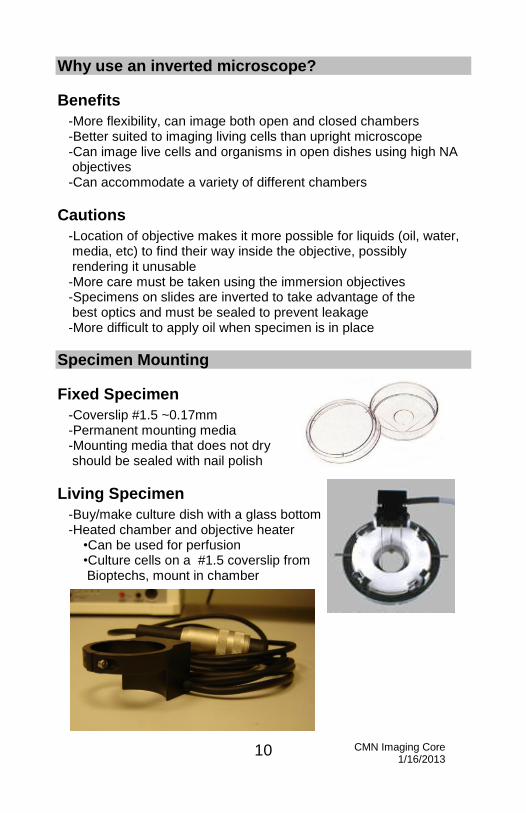
Why use an inverted microscope?
Benefits
-More flexibility, can image both open and closed chambers -Better suited to imaging living cells than upright microscope -Can image live cells and organisms in open dishes using high NA objectives -Can accommodate a variety of different chambers
Cautions
-Location of objective makes it more possible for liquids (oil, water, media, etc) to find their way inside the objective, possibly rendering it unusable -More care must be taken using the immersion objectives -Specimens on slides are inverted to take advantage of the best optics and must be sealed to prevent leakage -More difficult to apply oil when specimen is in place
Specimen Mounting
Fixed Specimen
-Coverslip #1.5 ~0.17mm -Permanent mounting media -Mounting media that does not dry should be sealed with nail polish
Living Specimen
-Buy/make culture dish with a glass bottom -Heated chamber and objective heater •Can be used for perfusion •Culture cells on a #1.5 coverslip from Bioptechs, mount in chamber

CMN Imaging Core 1/16/2013
11
Objectives The following objectives are on the objective turret: 10x HC Plan Fluotar Ph1 (dry) 40x HCX Plan Fluotar Ph2 (dry) 20x HC Plan Apo CS multi-imm 40x HCX Plan Apo CS oil 63x HCX Plan Apo CS oil 100x HCX Plan Apo CS oil We have an additional objective (63x water immersion) that can installed with Paula’s assistance.
Understanding Objectives Quality -Objectives are highest quality = expensive -Image is only as good as the objective
Numerical Aperture (NA) Measure of the width of the cone of light that the objective can gather -High NA objectives have: •High resolution •Brighter image •Shorter working distance
-NA > 1.0 – generally are immersion objectives
Correction collars -The following objectives have NA correction collars: 40x oil, 63x oil, 100x oil. Adjusting this collar will affect the resolution and brightness of the image, as well as the working distance. We recommend always leaving these collars in the maximum position. When looking at down at the objective, turning the collar completely clockwise will put collar in the maximum NA position. -The 20x objective has a correction collar for different immersion media : oil, water, glycerol.
CMN Imaging Core 1/16/2013
12
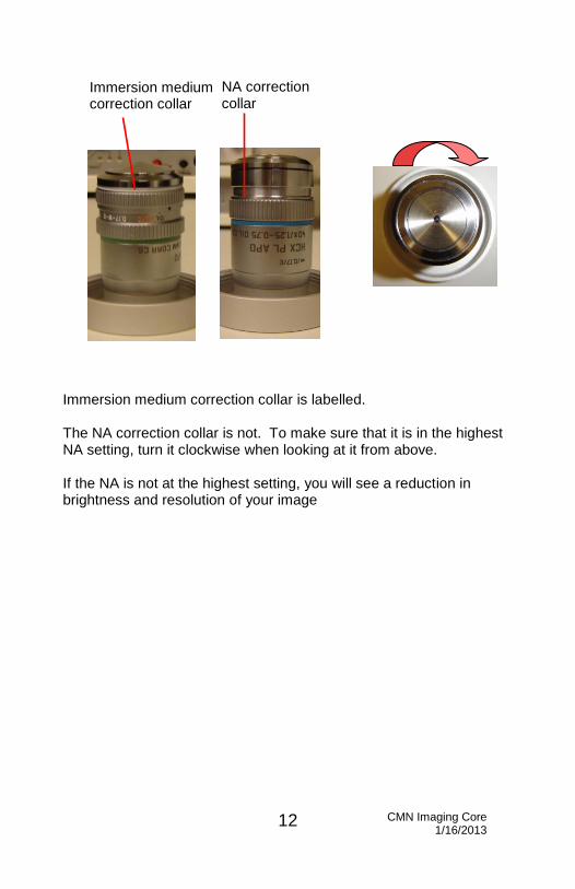
Immersion medium correction collar is labelled. The NA correction collar is not. To make sure that it is in the highest NA setting, turn it clockwise when looking at it from above. If the NA is not at the highest setting, you will see a reduction in brightness and resolution of your image
Immersion medium correction collar
NA correction collar

CMN Imaging Core 1/16/2013
13
Care of Objectives
Do not remove objectives -If you need a different objective than what is on the turret, contact Paula before scheduled use so it can be installed and available.
Immersion objectives -Use oil for all the immersion objectives -To use the 63x water objective, contact Paula for instructions -To use the 20x multi-immersion objective with water, contact Paula for instructions
Using oil -Always use Leica oil – do not mix oils -Use minimum amount necessary -Clean slides after use -Use only lens tissue to clean objectives – blot, don’t rub -Always clean objective after use with oil -Don’t drag dry objectives through the oil on the slide
Epifluorescence Filter Cubes The following filter cubes are installed on the turret. I3 – Fluorochromes: Alexa 488, Cy2, YFP N2.1 – Fluorochromes: Alexa 546, TRITC, Cy3 DAPI – Fluorochromes: DAPI We have two additional filter cubes (CFP and CY5) that can installed with Paula’s assistance.

CMN Imaging Core 1/16/2013
14
Phase and DIC Phase Contrast -Available with the dry objectives -Reveals the relative refractive index -Generates high contrast, which depends in part on the thickness of the specimen -Less suitable than DIC for overlaying with fluorescent images
DIC -Available with the immersion objectives -Reveals gradients in refractive index, so the resulting image tends to show edges -Generates low contrast -Better for overlaying with fluorescent images than phase
Blue-Green (Spirulina) Algae

CMN Imaging Core 1/16/2013
15
The Confocal Microscope and Workstation Layout
Nitrogen tank
Mercury bulb power supply (top) Microscope Power supply (bottom)
Scan Head 3 Fluorescent
PMTs
Transmitted Light PMT
Control Panel
Laser Launch -3 lasers -6 laser lines
CPU

CMN Imaging Core 1/16/2013
16
AOTF In place of excitation filters, our confocal system has an acousto-optical tunable filter -Allows for independently attenuating each laser line -Less “ Crosstalk “ with multi-color stainings -Less bleaching by optimized excitation intensity -Fast switching While the laser is scanning, it can be turned on in one spot and the next spot it can be turned off -Region-of-interest Scan Sample protection Bleaching experiments (FRAP, FRET) Activation/uncaging
Spectral Detectors In place of emission filters, our confocal system has spectral detectors. -Three confocal spectral detection channels -Stepless adjustable spectral emission bands -No limitations caused by filter characteristics -Adjust detection bandwidth manually or with pre-sets -Laser lines are blocked out

CMN Imaging Core 1/16/2013
17
This example shows two confocal spectral detectors and one transmitted light detector in an upright microscope configuration. Our confocal system has three confocal spectral detectors and one transmitted light detector in an inverted microscope configuration.
1. Laser 2. AOTF 3. Excitation Pinhole 4. Dichroic mirror (beam splitter) 5. “K”-scanner with rotator 6. Microscope and objective 7. Confocal detection pinhole 8. Prism 9. Spectral detector (PMT 1) 10. Spectral detector (PMT 2) 11. Transmitted light detector

CMN Imaging Core 1/16/2013
18
Crosstalk Fluorochromes excite and emit over a broad range of wavelengths,
so there is always the possibility of crosstalk.
Types
-Excitation Excitation wavelength activates two or more fluorophores -Emission Emission curve overlaps detection bandwidth of another fluorophore
Solutions -Dyes Choose dyes with Minimal overlap of excitation and emission spectra -Hardware Use spectral detectors Use sequential scanning -Software Adaptive Dye Separation Spectral Dye Separation
488
TRITC
Alexa 546
Spectra
Alexa 488
Spectra
TRITC
FITC
FITC
543
543
488
488

CMN Imaging Core 1/16/2013
19
Getting Started
Start the Leica Confocal Software
Double click on the Leica Confocal Software icon.
1. Turn
on the
nitrogen
tank
valve
2. Turn on the
mercury bulb
(top)
(On for 30 min,
off for 30 min)
3. Turn on the
microscope
(bottom)
4.Turn on the fans for
the lasers
(red switches)
5. Turn on the three
lasers (keys)
6. Turn on
the
computer, if
it is off.
7. Log in as
a user
CMN Imaging Core 1/16/2013
20
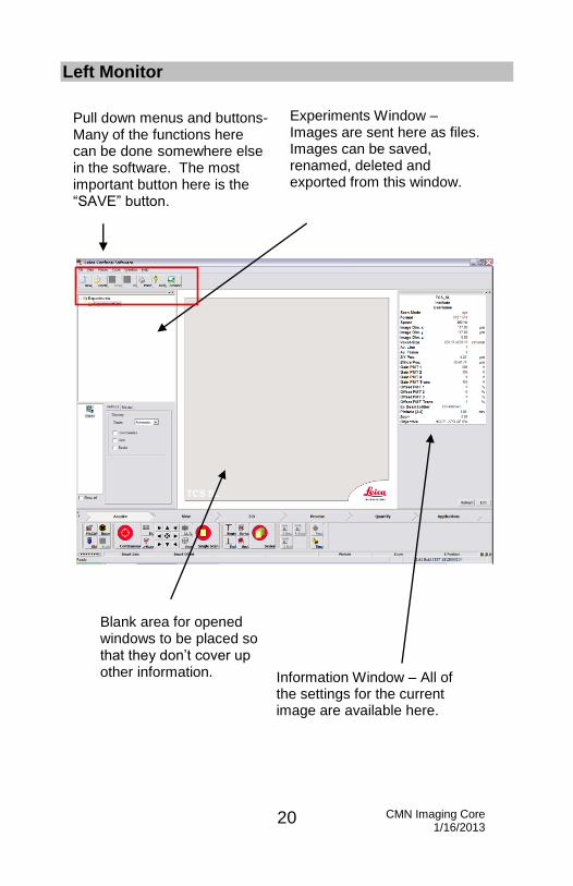
Left Monitor
Experiments Window – Images are sent here as files. Images can be saved, renamed, deleted and exported from this window.
Pull down menus and buttons- Many of the functions here can be done somewhere else in the software. The most important button here is the “SAVE” button.
Blank area for opened windows to be placed so that they don’t cover up other information. Information Window – All of
the settings for the current image are available here.

CMN Imaging Core 1/16/2013
21
Information Window

CMN Imaging Core 1/16/2013
22
Z Series controls
Menu buttons – Each opens a new set of tools. Generally, these are used in a left to right order.
Tools for acquiring images.
CMN Imaging Core 1/16/2013
23
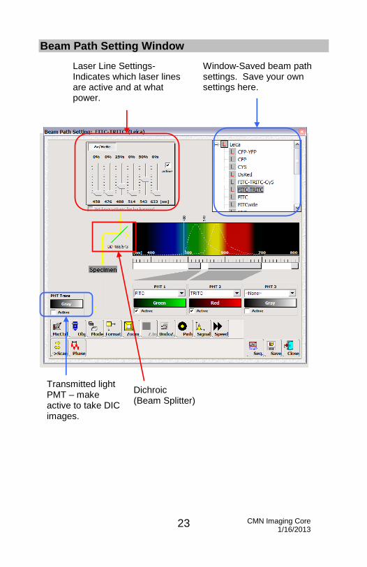
Beam Path Setting Window
Laser Line Settings-Indicates which laser lines are active and at what power.
Window-Saved beam path settings. Save your own settings here.
Dichroic (Beam Splitter)
Transmitted light PMT – make active to take DIC images.

CMN Imaging Core 1/16/2013
24
Format Button
Choose the resolution of the image to be collected. The default is 512 x 512.
Mode Button
Determines the type of scan that will occur. Default is xyz. Modes with “t” are timed.

CMN Imaging Core 1/16/2013
25
Obj button
Displays the objective currently in use. Also, can change the objective in use by clicking on the desired objective.
MicCtrl Button
To easily change the microscope settings between scanning and looking at your sample thru the eyepieces, select the “MicCtrl” button. Choose “Scan” if you want acquire images with the confocal software. Choose “Visual” if you want to look through the eyepieces of the microscope. If you get an error message when you try to acquire an image in the software check this setting to make sure that “Scan” is selected.

CMN Imaging Core 1/16/2013
26
Pinh Button
Displays the current pinhole setting. The default for each objective is 1 Airy Disk. Increasing the pinhole will increase the signal, but will also reduce the confocality of the image.
Speed Button
Displays the current scan speed, which is equivalent to exposure. Default is 400 Hz. Increasing the speed will decrease photobleaching and brightness of image, as well as the time it takes to acquire the image.

CMN Imaging Core 1/16/2013
27
Right Monitor
The Viewer Window
Viewer Toolbar- Buttons that will facilitate taking and displaying an image. Viewer Window – The
acquired images will be displayed here.

CMN Imaging Core 1/16/2013
28
Viewer Toolbar
Single, Tiled, Gall. and Ovl –Ways of determining the type of view that you would like in the viewer window.
Ch 1 thru Ch 4 – Selecting/Deselecting will determine which channels are displayed in the viewer window.
Q LUT and Lut – Buttons for optimizing the gain and offset, as well as adjusting the display of the image.
Buttons for acquiring images. Many buttons are duplications of what is under the Acquire menu.

CMN Imaging Core 1/16/2013
29
This shows a tiled view with an overlay. Three channels are displayed.
Collecting an image
Select the MicCtrl button. Set it to scan.

CMN Imaging Core 1/16/2013
30
The Beam Path Settings Window
Select the “Beam” button. The Beam Path Settings window will open. To select excitation and detection settings, double click on one of the options under the Leica directory in the Beam Path Settings window (blue arrow). The settings for FITC-TRITC are selected here.
Take the first image
Select “Single Scan” to take one scan of your image.

CMN Imaging Core 1/16/2013
31
The first scan on the right monitor. This image will be flipped on a horizontal axis as compared to what is seen through the eyepieces of the microscope.
Create an overlay of the two channels
Choose the “Ovl” button to create a merged image of the two channels.
CMN Imaging Core 1/16/2013
32
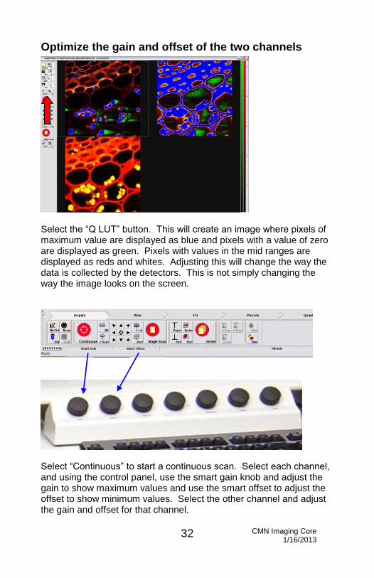
Optimize the gain and offset of the two channels
Select the “Q LUT” button. This will create an image where pixels of maximum value are displayed as blue and pixels with a value of zero are displayed as green. Pixels with values in the mid ranges are displayed as reds and whites. Adjusting this will change the way the data is collected by the detectors. This is not simply changing the way the image looks on the screen.
Select “Continuous” to start a continuous scan. Select each channel, and using the control panel, use the smart gain knob and adjust the gain to show maximum values and use the smart offset to adjust the offset to show minimum values. Select the other channel and adjust the gain and offset for that channel.

CMN Imaging Core 1/16/2013
33
This image has been adjusted, so that there are some maximum pixels and some minimum pixels, but nothing is saturated. To change the display back to colored image, simply click on Q LUT twice more. The gain and offset will need to be checked and adjusted each time a setting is changed.
Averaging
Averaging taking a single image
Select “Aver” Select single scan. Choose the number of frames you would like to average. Averaging two to four frames is most common. Select “Single Scan”. An image will be created in the Experiments window.

CMN Imaging Core 1/16/2013
34
The single scan is saved as an image in the Experiments window. The small red check on the file icon indicates that this is the image that is currently being shown on the right monitor.
Crosstalk
Check for Crosstalk
Reduce the 488 laser line to zero. Take a scan. Check the gain and offset.

CMN Imaging Core 1/16/2013
35
Because there is no signal in the FITC channel, we would say that there isn’t crosstalk in this direction.
Check for crosstalk from the other laser line
Reduce the 543 laser line to zero. Set the 488 laser line to its previous setting. Take a single scan.

CMN Imaging Core 1/16/2013
36
Because we see a signal in the TRITC channel, this shows crosstalk. Since we see signal in this channel it can mean that the 488 laser line is also exciting TRITC (excitation crosstalk) or that the emission curve for FITC is so large and the signal so strong that the detection slot for TRITC is actually detecting FITC.
Adjust beam path settings for crosstalk
Reduce the 488 laser line to 7% to see if that helps. The 488 laser line is very powerful and is generally used at a low level. Take a scan, adjust the gain and offset.

CMN Imaging Core 1/16/2013
37
There is still a large amount of crosstalk.
Change the detection slot
Using the slider, change the detection slot for the TRITC channel, so that the tail of the FITC emission is no longer being detected. Take a scan.

CMN Imaging Core 1/16/2013
38
The signal in the TRITC channel is reduced, but there is still some crosstalk. Because the emission tail of the FITC is so large and there is so much overlap into the TRITC channel, this would be a good situation to use sequential scan.

CMN Imaging Core 1/16/2013
39
Set up a sequential scan A sequential scan will take a scan with the settings for one channel and then the settings for another channel. It’s a good way to reduce crosstalk between channels.
Optimize the settings for each channel
Here, we are optimizing the settings for the FITC channel. We widened the detection slot and set the laser setting at reasonable level.
Take a scan. Optimize the gain and offset.

CMN Imaging Core 1/16/2013
40
Save the sequential setting
Select “Save” (blue arrow) in the Beam Path Settings window. The “Name of Parameter Setting” (yellow arrow) dialog will open. Name the setting (here Seq Green Convallaria) and click “OK”. The setting will be saved under “User” (red arrow) in the Beam Path Settings window.
Here we are optimizing the settings for the TRITC channel.

CMN Imaging Core 1/16/2013
41
The resulting image. Save this setting as for the other channel.
Load the sequential scan settings
Select “Seq” (blue arrow) in the Beam Path Settings window. The Sequential Scan Settings window will open. Select one of the channel settings that you saved (red arrow and highlighted) and click “Add” (yellow arrow) in the Sequential Scan Settings window. Then select the settings for the other channel and click “Add”.

CMN Imaging Core 1/16/2013
42
Here the settings for both channels have been added. Now choose a mode.

CMN Imaging Core 1/16/2013
43
Acquire an image using the sequential scan settings
With the “Sequential Scan Settings” window open, select “Single Scan” or “Continuous”. The resulting image will be collected using the sequential scan settings.
The resulting image. Check and adjust the gain and offset.
CMN Imaging Core 1/16/2013
44
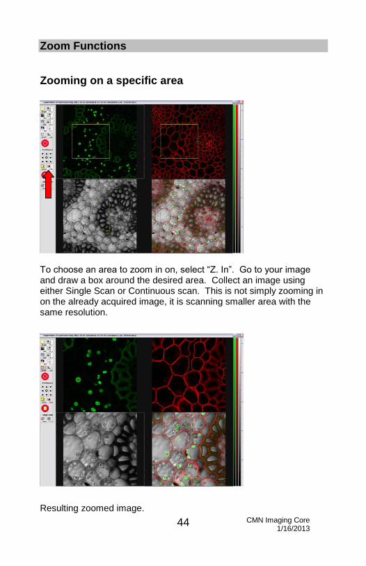
Zoom Functions
Zooming on a specific area
To choose an area to zoom in on, select “Z. In”. Go to your image and draw a box around the desired area. Collect an image using either Single Scan or Continuous scan. This is not simply zooming in on the already acquired image, it is scanning smaller area with the same resolution.
Resulting zoomed image.

CMN Imaging Core 1/16/2013
45
The amount of zoom is indicated in the information box.
Centered Zoom
Select the “Zoom” button. It will tell you what the current zoom is, as well as allow you to choose a specific zoom. This will zoom in on the center of the image. This is handy if you have several areas of interest in one larger image because you can use it to reduce the zoom to 1.00, so that you can see your original image again.

CMN Imaging Core 1/16/2013
46
DIC Take a DIC image
To take a DIC image, make sure that the the objective prism and the condenser prism are correct for the objective you are using, the transmitted light detector selection knob is set to scan, and that the analyzer is not in the light path. Then check the “Active” box for the transmitted light PMT.
DIC Image Overlay Image Take an image, adjust the gain and offset.

CMN Imaging Core 1/16/2013
47
Saving the Data
Saving the experiment
The program places all the images that you acquire in temporary memory until you save them. The images that are automatically sent to the experiment are the individual channels. If you have created an overlay of both channels, you will need to specifically save that. If the program crashes, upon restart it will notify you that there are temporary files and it will ask if you want to save them. If you exit out of the program purposely and choose not to save your images, they are not recoverable. To save the experiment
Select “Save” at the top of the screen.
Each lab will have a user folder on the D drive in the “users” folder, as well as a shortcut to that folder on the desktop. Save images only on the D drive. Here, McKinney lab is the user folder. To save, select “McKinney lab”.
Shortcut Icon on the desktop

CMN Imaging Core 1/16/2013
48
Rename the experiment (red arrow) and click “Save” (blue arrow). The experiment will be saved as a folder. The folder will contain all of the images acquired in the experiment. The software creates a file that tells what the names of the files are in the experiment folder. If you wish to change the name of your files and still be able to open those files in the Leica software, you must rename them from within the Leica software. If you go into Windows and rename the individual files there, when you try to reopen these images in the Leica software you will not be able to see them. A good way to eliminate this problem is to create a permanent archival copy of your raw data on CD or DVD. When you want to use the images, make a copy of the image and change that.

CMN Imaging Core 1/16/2013
49
Saving the overlay image
In order to save an image that looks like the Viewer window, right click on the images in the right monitor. Choose “Send to”, then “Experiment”, and then “All(snapshot)”. This will send an image that when you open it in Photoshop, will have the individual channels as well as the overlay in one composite image.
The icon for the snapshot (arrow) in the experiment window.
CMN Imaging Core 1/16/2013
50
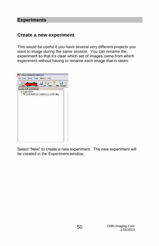
Experiments
Create a new experiment
This would be useful if you have several very different projects you want to image during the same session. You can rename the experiment so that it’s clear which set of images came from which experiment without having to rename each image that is taken.
Select “New” to create a new experiment. The new experiment will be created in the Experiment window.
CMN Imaging Core 1/16/2013
51
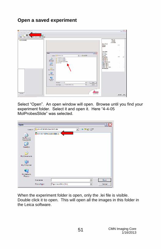
Open a saved experiment
Select “Open”. An open window will open. Browse until you find your experiment folder. Select it and open it. Here “4-4-05 MolProbesSlide” was selected.
When the experiment folder is open, only the .lei file is visible. Double click it to open. This will open all the images in this folder in the Leica software.

CMN Imaging Core 1/16/2013
52
Renaming images
To rename an image, right click on the name of the file and select rename.
Browsing all the images in an experiment
Choose “Browse”. This will display all the images in the experiment in a thumbnail format.

CMN Imaging Core 1/16/2013
53
Adding a scale bar
Check “Scale” in the Display menu, under Settings.
A scale bar will be added to your images. To format the scale bar to a specific length, choose the “Scale” button (arrow). A Scale Bar dialog will open.

CMN Imaging Core 1/16/2013
54
Type in the length of the scale bar and choose apply.
The resulting scale bar. In order to save the scale bar, you must right click on the image and send it to the experiment as a snapshot.

CMN Imaging Core 1/16/2013
55
Taking a Z series A Z series is a set of optical slices through the specimen, each at a different Z plane. It provides a more three-dimensional picture of the specimen.
Set the Start and End Points
Select the “Series” (red arrow) button. This will bring up the “Setting Z/Y-Position for Spatial Image Series” dialog. Start a Continuous scan. Using the control panel knob, change the Z position until you are at the top of the specimen. Select the “Begin” button (green arrow) to set this as the beginning of the Z series. Change the Z position in the opposite direction until you are at the bottom of the specimen and choose the “End” button (blue arrow) to set this as the end of the Z series.

CMN Imaging Core 1/16/2013
56
Set the number of sections
Here the beginning and end points have already been chosen. Select the “Sect” button to choose the number of sections or slices that will be taken. The software automatically chooses an “optimized” number of sections. To change the number of sections, select “Others” and the Z-configuration dialog will open.
Select the number of sections. A good rule of thumb is to double the optimized step size.

CMN Imaging Core 1/16/2013
57
Here, the step size has been changed to 0.24. This decreases the number of sections to 194.
Collect the series
Select the “Series” button to start the collection of the Z-series. The “Setting Z/Y-Position for Spatial Image Series” will show the progress of the Z-series. The green line in the box is the begin point. The red line in the box is the end point. The yellow line in the box is the current position.

CMN Imaging Core 1/16/2013
58
Viewing the Z-series
These are all the images in the Z-series. The select this view, choose “Gall” for the gallery view, “Single” to only have one image, both “Ch 1” and “Ch 2” since both channels are being captured and “Ovl” to have the overlay image.
The Z series file is named “Series” with a number, in this case Series027.
CMN Imaging Core 1/16/2013
59
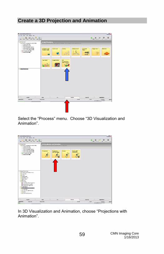
Create a 3D Projection and Animation
Select the “Process” menu. Choose “3D Visualization and Animation”.
In 3D Visualization and Animation, choose “Projections with Animation”.

CMN Imaging Core 1/16/2013
60
Select the Projection Type
There are six different choices of how the projection is created. Each of the windows displays a preview of what the projection will look like with that method. In this case, “Average Proj.” was chosen.
Preview the Projection
Choose “Preview” (blue arrow) to create a preview in the Result window. Choose “Apply” (red arrow) to create a file in the Experiments window that can be saved (red circle).
CMN Imaging Core 1/16/2013
61
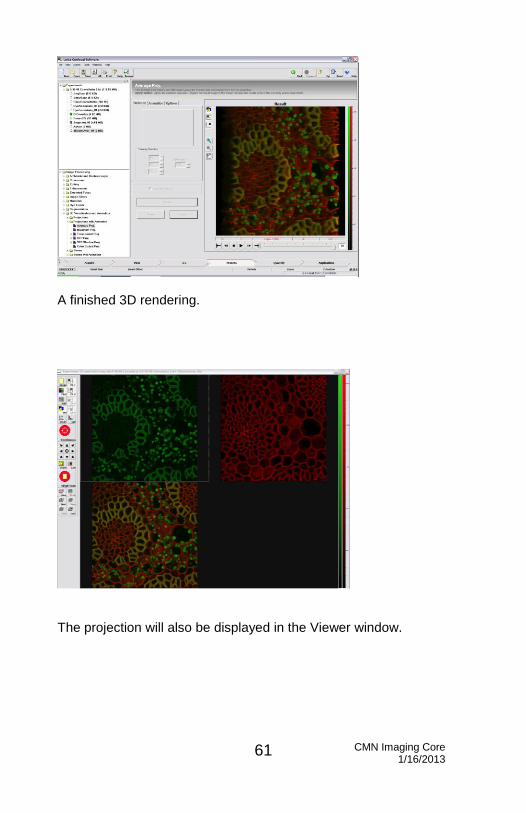
A finished 3D rendering.
The projection will also be displayed in the Viewer window.

CMN Imaging Core 1/16/2013
62
Export an Animation
Right click on the 3D Animation file in the Experiments window. Here it is named 3DAnimAver_00. Choose “Export”.
A “Save As” window will open. Name the animation and choose from the “Save as type” menu. Here “Export-Animation-Avi (*.avi) has been chosen. Choose “Save”. The animation will be saved as an AVI file.

CMN Imaging Core 1/16/2013
63
Archiving Data - Create a data disk
The computer has a CD/DVD writer as well as USB ports. Loading a CD or DVD into the CD/DVD drive will cause burning software to open automatically (the window above). If it does not open automatically, click on Nero SmartStart icon on the desktop.
Choose “Data”. Choose “Make a Data CD” or “Make a Data DVD”, depending on the type of media you are using.
Nero SmartStart icon

CMN Imaging Core 1/16/2013
64
The Nero Express Window
Open up your user folder. Select the items in the folder that you would like to save to the CD and drag them over to the CD project.
CMN Imaging Core 1/16/2013
65
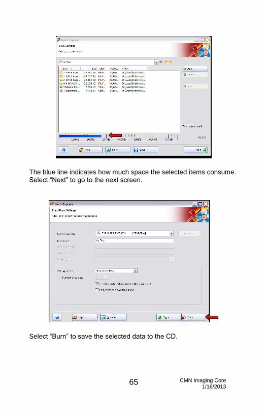
The blue line indicates how much space the selected items consume. Select “Next” to go to the next screen.
Select “Burn” to save the selected data to the CD.
CMN Imaging Core 1/16/2013
66
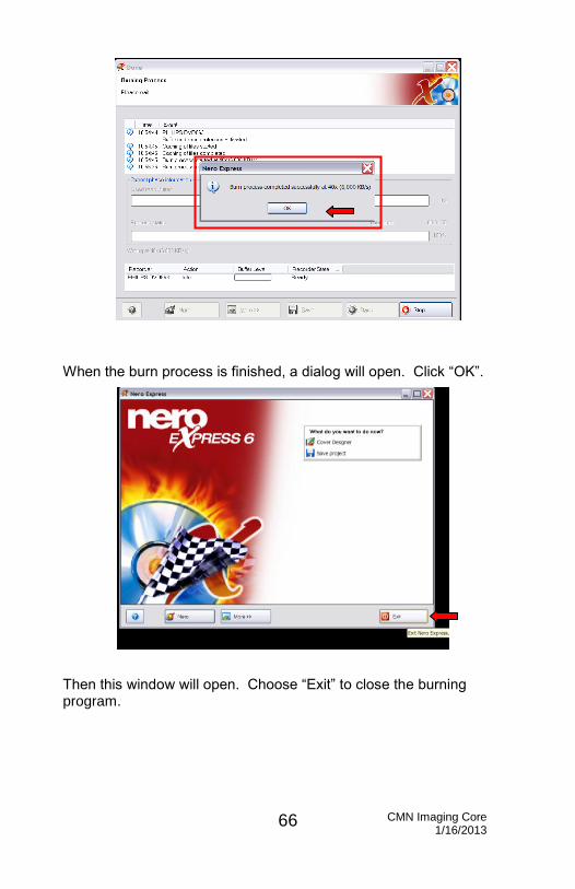
When the burn process is finished, a dialog will open. Click “OK”.
Then this window will open. Choose “Exit” to close the burning program.

CMN Imaging Core 1/16/2013
67
Logging off of the computer
After exiting out of the confocal software, log off of the computer. Click on the “Start” button.
Choose “Log Off”.

CMN Imaging Core 1/16/2013
68
Shutting Down
Alternate Shut Down Procedure: When finished taking images, shut off the lasers (the keys, step #3 above) and the mercury bulb (step #5 above). Proceed with the remainder of the steps (turn off the microscope, turn off the nitrogen tank, back up data, etc), except don’t turn off the fans (step#6)! When 15 minutes have elapsed, you may turn off the fans and cover the microscope.
7. Turn off the
nitrogen tank
4. Turn off the microscope (bottom) 5. Turn off the mercury bulb (top) 8. Put the cover back on microscope after the lamp housing has cooled
3.Turn off the lasers (keys), but not the red buttons 6. At least 15 minutes after #3! Turn off the fans for the lasers (red switches)
1. Shut down the Leica software
2. Log out as a user