Instruction Manual - GE Grid Solutions · installation instructions are applicable to the EPM 1000...
56
GE Consumer & Industrial Multilin Instruction Manual Manual P/N: 1601-0155-A7 Manual Order Code: GEK-106554F Copyright © 2007 GE Multilin GE Multilin 215 Anderson Avenue, Markham, Ontario Canada L6E 1B3 Tel: (905) 294-6222 Fax: (905) 201-2098 Internet: http://www.GEmultilin.com *1601-0155-A7* ISO9001:2000 G E M U L T I L I N R E G I S T E R E D GE Multilin's Quality Management System is registered to ISO9001:2000 QMI # 005094 UL # A3775
-
Upload
nguyenxuyen -
Category
Documents
-
view
214 -
download
0
Transcript of Instruction Manual - GE Grid Solutions · installation instructions are applicable to the EPM 1000...

GE Consumer & IndustrialMultilin
Instruction ManualManual P/N: 1601-0155-A7
Manual Order Code: GEK-106554F
Copyright © 2007 GE Multilin
GE Multilin
215 Anderson Avenue, Markham, Ontario
Canada L6E 1B3
Tel: (905) 294-6222 Fax: (905) 201-2098
Internet: http://www.GEmultilin.com
*1601-0155-A7*
ISO9001:2000GE MULT I L
I N
RE
GISTERED
GE Multilin's Quality Management System is
registered to ISO9001:2000
QMI # 005094UL # A3775

These instructions do not purport to cover all details or variations in equipment nor providefor every possible contingency to be met in connection with installation, operation, ormaintenance. Should further information be desired or should particular problems arisewhich are not covered sufficiently for the purchaser’s purpose, the matter should be referredto the General Electric Company.
To the extent required the products described herein meet applicable ANSI, IEEE, and NEMAstandards; but no such assurance is given with respect to local codes and ordinancesbecause they vary greatly.
© 2007 GE Multilin Incorporated. All rights reserved.
GE Multilin EPM 1000 Sub-Meter instruction manual.
EPM 1000 Sub-Meter is a registered trademark of GE Multilin Inc.
The contents of this manual are the property of GE Multilin Inc. This documentation is furnished on license and may not be reproduced in whole or in part without the permission of GE Multilin. The content of this manual is for informational use only and is subject to change without notice.
Part numbers contained in this manual are subject to change without notice, and should therefore be verified by GE Multilin before ordering.
Part number: 1601-0155-A7 (November 2007)

TOC
EPM 1000 SUB-METER – INSTRUCTION MANUAL TOC–1
Table of Contents
1: OVERVIEW GETTING STARTED ............................................................................................................1-1DESCRIPTION ........................................................................................................................ 1-1CONTACT INFORMATION ..................................................................................................... 1-1
APPLICATIONS ...................................................................................................................1-2STAND-ALONE METER ........................................................................................................ 1-2METERING SYSTEM .............................................................................................................. 1-2INTERIOR VIEW .................................................................................................................... 1-3CAUTIONS AND WARNINGS ............................................................................................... 1-3PROTECTIVE CONDUCTOR TERMINAL ............................................................................... 1-4PREVENTIVE MAINTENANCE ............................................................................................... 1-4
SPECIFICATIONS ................................................................................................................1-5TECHNICAL SPECIFICATIONS .............................................................................................. 1-5APPROVALS ........................................................................................................................... 1-6
ORDERING ..........................................................................................................................1-7CATALOG NUMBERS ............................................................................................................ 1-7MODIFICATIONS ................................................................................................................... 1-7ACCESSORIES ....................................................................................................................... 1-7
2: INSTALLATION GETTING READY ................................................................................................................2-1DETERMINATION OF METERING SYSTEM REQUIREMENTS .............................................. 2-1OVERVIEW OF METER WIRING .......................................................................................... 2-1
WIRING DIAGRAMS ..........................................................................................................2-2OVERVIEW ............................................................................................................................ 2-23-PHASE, 4-WIRE WYE ..................................................................................................... 2-31-PHASE, 3-WIRE CENTER-TAP-NEUTRAL 120/240 V .............................................. 2-43-PHASE, 4-WIRE CENTER-TAP-NEUTRAL 120/240 V DELTA ................................. 2-53-PHASE, 3-WIRE UNGROUNDED 480 V DELTA .......................................................... 2-63-PHASE, 3-WIRE CORNER-GROUNDED 480 V DELTA .............................................. 2-7WIRING FOR 1600 A AND 3200 A MODELS ................................................................ 2-8
INSTALLATION OF METER AND CURRENT TRANSFORMERS ..................................2-9PROCEDURE .......................................................................................................................... 2-9INTERNAL SHORTING TERMINAL ........................................................................................ 2-11
INSTALLING THE PULSE INPUTS ....................................................................................2-12PULSE INPUT OPTION ......................................................................................................... 2-12
INSTALLING THE GE TRANSPONDER ...........................................................................2-13PROCEDURE .......................................................................................................................... 2-13
3: USING THE METER MENU NAVIGATION ..........................................................................................................3-1USER INTERFACE .................................................................................................................. 3-1
CT MULTIPLIER TABLE ......................................................................................................3-4CT MULTIPLIERS .................................................................................................................. 3-4
VERIFYING METER FUNCTIONALITY .............................................................................3-5OVERVIEW ............................................................................................................................ 3-5VERIFYING VOLTAGE ........................................................................................................... 3-5VERIFYING KWH READING ................................................................................................. 3-5VERIFYING CURRENT AND ENERGY ................................................................................... 3-6
RESETTING THE DEMAND VALUES ...............................................................................3-7PROCEDURE .......................................................................................................................... 3-7

TOC–2 EPM 1000 SUB-METER – INSTRUCTION MANUAL
TOC
4: COMMUNICATIONS MODBUS COMMUNICATIONS ........................................................................................4-1RS485 WIRING FOR MODBUS ......................................................................................... 4-1RS232 WIRING FOR MODBUS ......................................................................................... 4-2MODBUS COMMANDS ......................................................................................................... 4-2FIXED MODBUS VALUES ..................................................................................................... 4-2MODBUS DATA REGISTER (R4 TYPE) GROUPS ................................................................ 4-2INSTANTANEOUS DATA ITEMS ............................................................................................ 4-332-BIT LONG AND FLOAT DATA FORMATS ..................................................................... 4-3
MODBUS ACTIVATION .....................................................................................................4-4OVERVIEW ............................................................................................................................ 4-4CONFIGURING A NEW HYPERTERMINAL SESSION .......................................................... 4-4CONFIRMING CONNECTION TO THE EPM 1000 ............................................................ 4-5LOGGING INTO THE METER ................................................................................................ 4-5ACTIVATING MODBUS COMMUNICATIONS ....................................................................... 4-6CHANGING MODBUS SETTINGS ......................................................................................... 4-7LOGGING OUT ...................................................................................................................... 4-7DISABLING MODBUS COMMUNICATIONS ......................................................................... 4-7
MODBUS MEMORY MAP ..................................................................................................4-8MEMORY MAP ...................................................................................................................... 4-8
5: MISCELLANEOUS REVISION HISTORY ...........................................................................................................5-1RELEASE DATES ................................................................................................................... 5-1CHANGES TO THE MANUAL ................................................................................................ 5-1
WARRANTY .........................................................................................................................5-4GE MULTILIN WARRANTY .................................................................................................. 5-4
INDEX

EPM 1000 SUB-METER – INSTRUCTION MANUAL 1–1
EPM 1000 Single Point Submetering System
Chapter 1: Overview
GE Consumer & IndustrialMultilin
Overview
1.1 Getting Started
1.1.1 DescriptionThank you for purchasing the GE Multilin EPM 1000 sub-meter to monitor energy for your residential, commercial, or industrial applications. At GE Multilin, we pride ourselves by providing our customers with best-in-class products, which have been carefully selected by GE to best serve your solution needs.
The EPM 1000 is sold in KWh or Demand meter versions and is available for 120/208V and 277/480V applications. An integrated liquid crystal display (LCD) is standard on all versions, providing local access to real-time and historical data. The meter provides two standard communication modes: power line communications (PLC), which utilizes existing AC power lines as the communication medium, eliminating dedicated wiring, and Modbus (RS232, RS485, modem).
The EPM 1000 is packaged with either solid or split core CTs in various amperages to suit both new construction and retrofit applications.
Note The EPM 1000 is primarily used for commercial and industrial applications and is available in voltages ranging from 120 to 600 V in both wye and delta forms. The following installation instructions are applicable to the EPM 1000 meter only.
1.1.2 Contact InformationFor assistance and contact information in connection with meter internal program setup and configuration please contact GE Multilin.

1–2 EPM 1000 SUB-METER – INSTRUCTION MANUAL
CHAPTER 1: OVERVIEW
1.2 Applications
1.2.1 Stand-Alone MeterThe GE Multilin EPM 1000 can be installed as a stand-alone device that is locally accessed via the LCD or remotely accessed via modem. A modem can be installed in each meter allowing the meter(s) to be read remotely.
1.2.2 Metering SystemThe GE Multilin EPM 1000 family of meters are ideally designed to comprise a metering system within a residential/commercial building or industrial site. This metering system can measure electrical usage for each tenant, cost center, or common area space and communicate this information over the building's power wires or dedicated communication wiring (RS485). A metering system is comprised two or more EPM 1000 meters and a communication transponder (see figure below). The transponder collects all of the metering data via the AC power lines and communicates data to an optional transponder.
FIGURE 1–1: Overview of Transponder Functionality
709704A1.CDR

CHAPTER 1: OVERVIEW
EPM 1000 SUB-METER – INSTRUCTION MANUAL 1–3
1.2.3 Interior ViewThe interior of the EPM 1000 is shown below.
FIGURE 1–2: Interior View of the EPM 1000
Note Where the and symbols are seen on the EPM 1000 meter, the manual must be consulted to determine the nature of any potential hazard and/or actions to be taken.
1.2.4 Cautions and Warnings
• Do not install if the device is damaged. Inspect the housing for obvious defects such as cracks in the housing.
• If the device is installed or used in a manner not specified by accompanying documents, the protection of the device may be impaired.
• If the device functions abnormally, proceed with caution. The protection of the device may be impaired.
• Do not install the meter around combustible gas or gas vapor.
• Do not install the meter in an electrical service with current or voltage outside of the specified limit of the device.
• Do not operate the meter with the cover removed.
• To avoid electric shock, disconnect mains before replacing fuses!
• See instructions for connection diagram.
• Risk of electric shock. Beware of working around this meter when the voltage is live.
• For continued protection against fire, replace only with fuses of specified voltage and current rating.
709703A1.CDR

1–4 EPM 1000 SUB-METER – INSTRUCTION MANUAL
CHAPTER 1: OVERVIEW
1.2.5 Protective Conductor TerminalSecurely fasten one end of the earthing wire so that the screw cuts the paint on the back box. Securely fasten other end of the wire to a true earth ground connection. When earthing to the electrical conduit, use continuous pipes, bending when necessary instead of using couplers.
1.2.6 Preventive MaintenanceThere are no necessary preventative maintenance or inspection.
A Toshiba CR2032 coin battery is used in each device and is intended to be good for decades before replacement. Return to manufacturer for replacement.

CHAPTER 1: OVERVIEW
EPM 1000 SUB-METER – INSTRUCTION MANUAL 1–5

1–6 EPM 1000 SUB-METER – INSTRUCTION MANUAL
CHAPTER 1: OVERVIEW
1.3 Specifications
1.3.1 Technical Specifications
OPERATING SPECIFICATIONSVoltage: ...............................................................120, 240, 277, 347, 480, 600 V (90% to 110%)Frequency: .........................................................60 HzPower:..................................................................2 W for 120V; 5 W for 220 to 600 V
ENVIRONMENTUsage:..................................................................For indoor use onlyTemperature: ....................................................–20°C to +60°CHumidity: ............................................................0 to 95% R.H. (non-condensing)Pollution Degree: ............................................1Maximum altitude:.........................................2000 m
CONTROL POWERInput: ....................................................................120 V phase A to neutral
277 V phase A to neutral480 V phase to phase(internally powered through metered voltage; no external source is required)
Frequency: .........................................................50 to 60 HzOperating power: ...........................................2 watts for 120 V
5 watts for 277 V and 480 VFuses: ...................................................................1 - Buss fuse 250 V / 500 V 0.25 A / 0.125 A slow-acting
3 - Buss fuse 250 V /600 V 4.0 A fast-acting
TYPE TESTSTransient/surge suppression: ..................ANSI C37.90.1-1989Installation category: III. .............................This product falls under Installation Category III because
of its distribution level, fixed installation and has smaller transient overvoltages than an Installation Category IV.
METERINGMetered Voltage: ............................................120, 220, 240, 277, 347, 380, 480, 600 V Delta or Wye, 50/
60 HzCurrent Input: ...................................................0.1 A, 5.0 ASecondary inputs: ..........................................50 to 4000 A primary availableMinimum current sensitivity:.....................0.06 A
INPUT AND OUTPUT CONNECTIONSSee installation diagram
INSULATION OF EXTERNAL CIRCUITSSee installation diagram
PHYSICALDimensions:.......................................................13.5"H × 8.5"W × 4.5"D
1.3.2 Approvals
APPROVALSANSI: .....................................................................C12.1 and C12.16 accuracy

CHAPTER 1: OVERVIEW
EPM 1000 SUB-METER – INSTRUCTION MANUAL 1–7
UL and CUL: ......................................................recognized under E204142

1–8 EPM 1000 SUB-METER – INSTRUCTION MANUAL
CHAPTER 1: OVERVIEW
1.4 Ordering
1.4.1 Catalog NumbersThe order codes for the EPM 1000 are indicated below.
For example, for demand metering applications with 277/480 V AC system voltage, 1500 A mains, 60 Hz, on an existing facility (split-core CTs), the required order code is PL1000480SP162D.
1.4.2 ModificationsThe following modifications are available:
– PL1000PULSIN10: pulse inputs
– PL1000MOD: Modbus communications
1.4.3 AccessoriesThe following accessories are available:
Table 0EPM 1000 Order CodesPL1000 – * – * – *
Base Unit PL1000 | | | EPM 1000 Sub-MeterSupplyVoltage
208 | | 120/208 volts connection480 | | 277/480 volts connection
CurrentTransformers
SP101 | Split-core, 100 A CTs (set of 3)SP201 | Split-core, 200 A CTs (set of 3)SP401 | Split-core, 400 A CTs (set of 3)SP801 | Split-core, 800 A CTs (set of 3)SP162 | Split-core, 1600 A CTs (set of 3)SP322 | Split-core, 3200 A CTs (set of 3)SL050 | Solid-core, 50 A CTs (set of 3)SL101 | Solid-core, 100 A CTs (set of 3)SL201 | Solid-core, 200 A CTs (set of 3)SL401 | Solid-core, 400 A CTs (set of 3)
DemandVersion
K kWh versionD Demand version
Transponder Models Voltage Options Description
PL MODXPONDER120V 120/208* Modem data collector for PLC
PL 485XPONDER120V 120/208 RS485 data collector for PLCPL RFXPONDER120V 120/208 Wireless data collector for PLCPL MODXPONDER277V 277/480 Modem data collector for PLCPL 485XPONDER277V 277/480 RS485 data collector for PLCPL MODXPONDER347V 347/600 Modem data collector for PLCPL 485XPONDER347V 347/600 RS485 data collector for PLC

CHAPTER 1: OVERVIEW
EPM 1000 SUB-METER – INSTRUCTION MANUAL 1–9
Note The transponder can handle up to 150 meter points (i.e. 150 EPM 1000 or 12 MC-5/12).
* same model works for 120/240 V modem has RS485 and RS232 standard

1–10 EPM 1000 SUB-METER – INSTRUCTION MANUAL
CHAPTER 1: OVERVIEW

EPM 1000 SUB-METER – INSTRUCTION MANUAL 2–1
EPM 1000 Single Point Submetering System
Chapter 2: Installation
GE Consumer & IndustrialMultilin
Installation
2.1 Getting Ready
2.1.1 Determination of Metering System RequirementsDetermine if the application is for a metering system or for a stand-alone meter. If the application is for a stand-alone meter, proceed directly to the next section. If the application is for a metering system, then please read Installing the GE Transponder on page 2–13.
2.1.2 Overview of Meter WiringAlthough this document treats the installation and certification stages separately, this does not imply that the recommended procedure is to install the entire system at once and then proceed to certification.
The recommended procedure is to install and certify the system in stages. By doing this, systematic error can be corrected before it propagates through the entire installation. To follow the recommended procedure, divide the job up into manageable stages and install and certify at each stage before proceeding to the installation of the next stage.
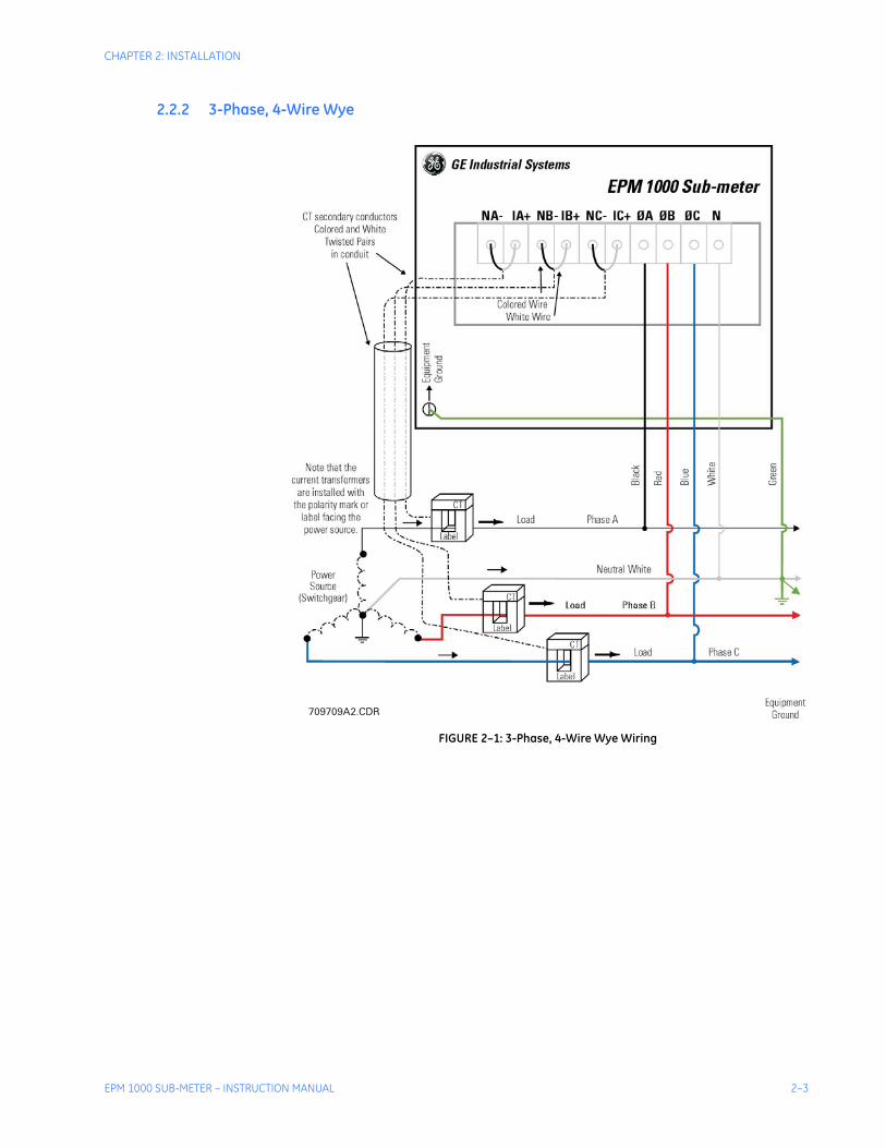
For the purposes of this discussion, the colors black, red and blue have been chosen to distinguish among the three phases of a three-phase network. White is the designated color of neutral and green is the color of earth ground. Please substitute the correct color according to local electrical code. For a two-phase installation, ignore the third phase (the blue phase in the following description).
Failure to follow the proper procedures and reference the correct wiring diagram can result in damage to the equipment and/or physical harm.

2–2 EPM 1000 SUB-METER – INSTRUCTION MANUAL
CHAPTER 2: INSTALLATION
2.2 Wiring Diagrams
2.2.1 OverviewReview the following wiring diagrams and select the one that matches your installation requirements and part number using the following table.
Table 2–1: Wiring Diagram / Model Reference
Figure Applicable Models
FIGURE 2–1: 3-Phase, 4-Wire Wye Wiring on page 2–3PL1000208S****KPL1000208S****DPL1000480S****KPL1000480S****D
FIGURE 2–2: 1-Phase, 3-Wire Center-Tap-Neutral 120/240 V Wiring on page 2–4
PL1000208S****KPL1000208S****D
FIGURE 2–3: 3-Phase, 4-Wire Center-Tap-Neutral 120/240 V Delta Wiring on page 2–5
PL1000208S****KPL1000208S****D
FIGURE 2–4: 3-Phase, 3-Wire Ungrounded 480 V Delta Wiring on page 2–6 PL1000480DELTA
FIGURE 2–5: 3-Phase, 3-Wire Corner-Grounded 480 V Delta Wiring on page 2–7 PL1000480DELTA
FIGURE 2–6: CT Terminations for 1600 A and 3200 A Models on page 2–8
PL1000***SP162*PL1000***SP322*
CHAPTER 2: INSTALLATION
EPM 1000 SUB-METER – INSTRUCTION MANUAL 2–3
2.2.2 3-Phase, 4-Wire Wye
FIGURE 2–1: 3-Phase, 4-Wire Wye Wiring
709709A2.CDR

2–4 EPM 1000 SUB-METER – INSTRUCTION MANUAL
CHAPTER 2: INSTALLATION
2.2.3 1-Phase, 3-Wire Center-Tap-Neutral 120/240 V
FIGURE 2–2: 1-Phase, 3-Wire Center-Tap-Neutral 120/240 V Wiring
709705A2.CDR

CHAPTER 2: INSTALLATION
EPM 1000 SUB-METER – INSTRUCTION MANUAL 2–5
2.2.4 3-Phase, 4-Wire Center-Tap-Neutral 120/240 V Delta
FIGURE 2–3: 3-Phase, 4-Wire Center-Tap-Neutral 120/240 V Delta Wiring
709708A1.CDR

2–6 EPM 1000 SUB-METER – INSTRUCTION MANUAL
CHAPTER 2: INSTALLATION
2.2.5 3-Phase, 3-Wire Ungrounded 480 V Delta
FIGURE 2–4: 3-Phase, 3-Wire Ungrounded 480 V Delta Wiring
709707A1.CDR

CHAPTER 2: INSTALLATION
EPM 1000 SUB-METER – INSTRUCTION MANUAL 2–7
2.2.6 3-Phase, 3-Wire Corner-Grounded 480 V Delta
FIGURE 2–5: 3-Phase, 3-Wire Corner-Grounded 480 V Delta Wiring
709706A1.CDR

2–8 EPM 1000 SUB-METER – INSTRUCTION MANUAL
CHAPTER 2: INSTALLATION
2.2.7 Wiring for 1600 A and 3200 A ModelsFor the 1600 A and 3200 A models (order codes PL1000***SP162* and PL1000***SP322*), the CT terminations are made on the HCA-2 module to allow the EPM 1000 to accept 5 A secondary current inputs. CAREFULLY observe the following figure and terminate the CT leads on the included HCA-2 module, NOT the fuse block.
FIGURE 2–6: CT Terminations for 1600 A and 3200 A Models
709717A1.CDR

CHAPTER 2: INSTALLATION
EPM 1000 SUB-METER – INSTRUCTION MANUAL 2–9
2.3 Installation of Meter and Current Transformers
2.3.1 Procedure
Note The use of the following procedure is mandatory. Certification requires a visual inspection of the current transformers and the voltage taps on the incoming feeder phase wires.
Mount the back box to the wall, or in the wall for flush mount installations. Connect the breaker panel box to the back box of the meter with a metal conduit through which the 3 or 4 feeder phase taps and the 6 CT wires will be run. Make sure to use at least a ¾-inch ID conduit to allow for all 9 or 10 wires to pass easily.
Locate the incoming feeder phase (hot) wires at the top of the breaker panel. Tape the incoming feeder wires according to phase with black, red and blue electrical tape for identification purposes.
Extend the CT wires with AWG #16 stranded with black, red and blue jackets so as to be the correct length to pass through the conduit and reach the fuse block in the meter back box. Extend the white wire of each CT with a white wire, but place a black, red or blue electrical tape on the end of the extended wire to identify the correct neutral. Refer to these CT white wires with tape as white/black, white/red and white/blue respectively.
Remove the incoming feeder hot wires one at a time and place each CT over the proper feeder wire. Make sure that the colors of the CT leads correspond to the color of the tape on the phase feeder. Make certain that the white wire from the CT is closest to the line side of the feed, away from the top of the breaker panel. For split-core CTs, make sure that the X1 is toward the line side. Run the CT secondary wires through conduit to the back box of the meter.
Tap the three feeder wires with AWG #12 stranded wire with black, red and blue jackets taking care to match the color of the insulation of the #12 wires to correspond to the color of the tape on the feeder wire.
If the service is 4-wire, tap the neutral connection with a #12 AWG stranded wire with a white jacket.
Run the six (6) current transformer wires black, white/black, red, white/red and blue, white/blue to IA+, NA–, IB+, NB–, IC+, NC– respectively on the fuse block (see Internal Fuse Block on page 2–11).

2–10 EPM 1000 SUB-METER – INSTRUCTION MANUAL
CHAPTER 2: INSTALLATION
Take the black, red, blue and white (if available) #12 AWG feeder phase tap wires and run them to ⇔A, ⇔B, ⇔C, and N (if available) respectively (see Internal Fuse Block on page 2–11).
Plug the fuse block into the meter head and hang the meter head on the back box.
Close up the breaker panel until the certification inspector arrives.

CHAPTER 2: INSTALLATION
EPM 1000 SUB-METER – INSTRUCTION MANUAL 2–11
2.3.2 Internal Shorting Terminal
FIGURE 2–7: Internal Fuse Block
709721A1.CDR

2–12 EPM 1000 SUB-METER – INSTRUCTION MANUAL
CHAPTER 2: INSTALLATION
2.4 Installing the Pulse Inputs
2.4.1 Pulse Input OptionThe EPM 1000 with the Pulse Input option will provide a 5-wire harness from the back of the meter head. The color coding on the harness is as follows and the M# and Q# refers to meter registers that will appear if the meter has pulse inputs:
• COMMON (WHITE)
• M2 Q14 (GREEN)
• M2 Q13 (ORANGE)
• M1 Q14 (RED)
• M1 Q13 (BLACK)

CHAPTER 2: INSTALLATION
EPM 1000 SUB-METER – INSTRUCTION MANUAL 2–13
2.5 Installing the GE Transponder
2.5.1 ProcedureIf your application is for a metering system, use the following procedure to install the transponder.
Plan for the transponders.
• Determine the number of services in order to determine the number of transponders. Do not rely solely on the memory of the local engineers or of the existing drawings. Drawings may not have been properly updated to reflect as-built conditions and memories are not always accurate. Use these as guidelines and then perform a survey. Open electrical cabinets as necessary and locate every master meter from the utility.
• Make careful note of the voltages of the various transponders.
Determine the number of tenant spaces.
• In residential applications, this number should be fixed. Often apartments are laid out on a grid, such as by floor and by line. In this case, the number of meters is simply the number of floors times the number of lines. This information is needed before any meters are installed or entered into the transponders.
• Determine which service feeds each metering point. This information is vital to proper system operation. Without this information, a laborious process of trial and error is necessary to determine which transponder must be used for each meter. This will increase the cost of certification and commissioning of the system.
Determine the service size and type of meter for each metering point.
• In residential applications, this is probably a constant amperage across the entire job (either 50A or 100A with Series 10 meters).
Determine the number of telephone lines required and ensure the lines are installed before the installation of any metering equipment.
Determine the number of independent services.
• Typically there is one service per distribution transformer that feeds the property, unless distribution transformers have parallel secondaries, which is rare.
Locating the best location for each transponder.
This is the closest point to the first point at which the feeders for the service branch out into sub-feeders. To find this point, follow the feeders from the secondary of the distribution transformer (or the service entrance if the transformer is off the property) and place the transponder at the last point before the feeder breaks into multiple feeders.

2–14 EPM 1000 SUB-METER – INSTRUCTION MANUAL
CHAPTER 2: INSTALLATION
Determine which of the transponders should have a telephone modem, and order a telephone line to terminate at that point. Do not proceed with the installation until the telephone line is installed.
After the telephone line is installed, install the transponder with the modem next to the telephone line. Install all three phases and the neutral to the transponder (see Installation of Meter and Current Transformers on page 2–9 for details).
If there is more than one transponder, install the other transponders and the interconnecting RS485 line, if required, which links all of the transponders (Go directly to Installation of Meter and Current Transformers on page 2–9 if there is only one transponder in the system or if each transponder in the system has a modem and telephone line connection).
• An RS485 line is a pair of wires, AWG #20 or larger in diameter, which begins at one transponder where a terminator is placed.
• The RS485 line runs from transponder to transponder ending at the final transponder, where another terminator is placed.
Note It is critically important that there should never be three RS485 pairs entering or leaving a transponder box.
• For the two transponders which have terminators, only one RS485 pair leaves each box.
• For the other transponders, if there are more than two, exactly two RS485 lines should leave the box: each line goes to another transponder in the daisy-chain. Only one modem should be installed in a data link system. If there are two or more modems in a data link system, the transponders will not communicate with each other.
• There may be no more than 32 transponders on a daisy-chain. If there are more than 32, special care must be taken, which is beyond the scope of these instructions.
If possible, run the RS485 lines in a conduit to protect them from damage.
Note It is critically important to observe the polarity of the wires. The RS485 data link uses a black and yellow color code. Match black to black and yellow to yellow; otherwise the data link will not work.
To test the data link, measure the DC voltage across the yellow to black wire. This should measure between 0.1 and 0.3 V. If it is negative or outside of that range, re-check all of the transponder boxes according to the above specifications.
EPM 1000 SUB-METER – INSTRUCTION MANUAL 3–1
EPM 1000 Single Point Submetering System
Chapter 3: Using the Meter
GE Consumer & IndustrialMultilin
Using the Meter
3.1 Menu Navigation
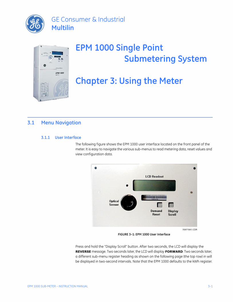
3.1.1 User InterfaceThe following figure shows the EPM 1000 user interface located on the front panel of the meter. It is easy to navigate the various sub-menus to read metering data, reset values and view configuration data.
FIGURE 3–1: EPM 1000 User Interface
Press and hold the “Display Scroll” button. After two seconds, the LCD will display the REVERSE message. Two seconds later, the LCD will display FORWARD. Two seconds later, a different sub-menu register heading as shown on the following page (the top row) in will be displayed in two-second intervals. Note that the EPM 1000 defaults to the kWh register.
709719A1.CDR

3–2 EPM 1000 SUB-METER – INSTRUCTION MANUAL
CHAPTER 3: USING THE METER
Releasing the display scroll button at a given submenu heading will allow you to cycle through the registers listed under the selected submenu heading. Pressing and releasing the display button will advance to the next block of registers in the sub-menu.
To reverse scrolling direction at either the heading level or within a submenu, press and hold the display scroll button. When REVERSE is displayed after two seconds, release the display scroll button. You can now go backwards through the menu selections by pressing and releasing the display scroll button.
To go back to the forward scrolling option, follow the same procedure, except release the display scroll button when FORWARD is displayed.

CHAPTER 3: USING THE METER
EPM 1000 SUB-METER – INSTRUCTION MANUAL 3–3
FIGURE 3–2: EPM 1000 Display Structure
709720A1.CDR

3–4 EPM 1000 SUB-METER – INSTRUCTION MANUAL
CHAPTER 3: USING THE METER
3.2 CT Multiplier Table
3.2.1 CT Multipliers
Note The following table MUST BE used to verify the correct current readings, based on the rating of the CT installed.
Note The multiplier that corresponds with the CT rating MUST BE applied to the current reading shown on the display of the EPM 1000 by multiplying that reading by the multiplier shown above. The multiplier MUST also be applied in the same manner when calculating kW and kWh. Failure to use the appropriate multiplier will result in an incorrect diagnosis of the meter's functionality and incorrect revenue billing.
Table 3–1: CT Multiplier Table
CT Size Multiplier
50 A × 0.5
100 A × 1
200 A × 2
400 A × 4
800 A × 8
1600 A × 32
3200 A × 64

CHAPTER 3: USING THE METER
EPM 1000 SUB-METER – INSTRUCTION MANUAL 3–5
3.3 Verifying Meter Functionality
3.3.1 OverviewOnce you have familiarized yourself with the EPM 1000 menu structure, it is critical to verify that the meter and CTs are properly installed.
Note To correctly diagnose the meter, there must be loads on all three phases of the meter.
3.3.2 Verifying VoltagePress and hold the Display Scroll button until the following menu heading is displayed:
Release the Display Scroll button. Scroll down by pressing and releasing the Display Scroll Button until the following submenu is displayed:
Verify that phases A, B and C are displaying voltages; i.e., for a 120 V AC, the reading should be 117 V +10%/–15%.
3.3.3 Verifying kWh ReadingPress and hold the Display Scroll button until the following menu heading is displayed:
Release the Display Scroll button. Scroll down by pressing and releasing the Display Scroll button until the following sub-menu is displayed:
Verify that the kWh value increases as you view the LCD.
Phase DiagnosticRegisters
Volts 125.3 A124.0 B 124.7 C
kWH RegistersRegisters
AllHrs kWH1.046

3–6 EPM 1000 SUB-METER – INSTRUCTION MANUAL
CHAPTER 3: USING THE METER
3.3.4 Verifying Current and EnergyPress and hold the Display Scroll button until the following menu heading is displayed:
Release the Display Scroll button. Scroll down by pressing and releasing the Display Scroll button until the following submenu is displayed:
The A(mperage) reading in the display above will always be a positive number, even if the CT was incorrectly installed. Check the reading to see if it indicates the approximate current you expected. Remember that this applies to Phase 1 only. If all the numbers on the multiplier screen were 1.00 and the current transformers are 100:0.1, your multiplier is 1 and the readings are the actual values. If the CTs are 200:0.1, multiply the current reading by 2.
The W(att) reading will also count forward as your view the LCD. A negative power reading is indicative of an incorrectly installed CT, or one that is cross-phased with the wrong voltage (phase) leg. The R(eactive) reading can be negative, depending on the nature of the load. Negative values indicate a capacitive load while positive values indicate an inductive load.
Scroll down by pressing and releasing the Display Scroll Button until the following submenu is displayed:
Under normal conditions the phase angle (x.x°) should be close to 0° and the power factor should be a number close to 1 (one). Resistive loads will have a power factor close to 1, while inductive loads will typically reflect a power factor between 0.80 to 0.95, or even lower.
If the phase angle on the lower left is a number close to 180°, it indicates the CT was installed backwards, or 180° out-of-phase. If the number is close to 120°, at least two CTs have been cross-phased, and a similar number will appear in the phase angle data in Phase 2.
To view screens for Phases 2 and 3, repeat the same steps as above.
Phase DiagnosticRegisters
Phase 1 7.468 A818.7 W 100.5 R
Ph 1 935.4 VA6.8° .875 PF

CHAPTER 3: USING THE METER
EPM 1000 SUB-METER – INSTRUCTION MANUAL 3–7
3.4 Resetting the Demand Values
3.4.1 ProcedureUse the following procedure to reset the Demand registers to zero:
Press and hold the Demand Reset button.
• The LCD will initially display a copyright message.• The LCD will then display the Dmdreset event screen:
Keep the Demand Reset button depressed until the screen updates and displays the current date and time. This signifies that the demand has been reset.
Dmdreset 120:00 06/14/2003

3–8 EPM 1000 SUB-METER – INSTRUCTION MANUAL
CHAPTER 3: USING THE METER

EPM 1000 SUB-METER– INSTRUCTION MANUAL 4–1
EPM 1000 Single Point Submetering System
Chapter 4: Communications
GE Consumer & IndustrialMultilin
Communications
4.1 Modbus Communications
4.1.1 RS485 Wiring for ModbusThe wiring for Modbus communications for two-wire and four-wire RS485 is indicated below.
For two-wire RS-485:
For four-wire RS-485:
FIGURE 4–1: RS-485 Serial Connections
Color Function DB-9 PinoutYellow RX (+) 2
Black TX (–) 8
Color Function DB-9 PinoutYellow (A) RX (+) 2
Black (B) RX (–) 3
Green (Y) TX (+) 7
Red (Z) TX (–) 8
709725A1.CDR

4–2 EPM 1000 SUB-METER– INSTRUCTION MANUAL
CHAPTER 4: COMMUNICATIONS
Note The EPM 1000 optical port is disabled for units with 2-wire RS485 connections.
4.1.2 RS232 Wiring for ModbusThe wiring for Modbus communications for RS232 is indicated below.
4.1.3 Modbus CommandsThe EPM 1000 is capable of acting as a remote slave unit to a Modbus master device via modem, RS232, RS485, or PLC. Up to 32 EPM 1000 meters (or other RS485 devices) can be daisy-chained together on a single LAN.
The EPM 1000 communicates at a default baud rate of 19200, with no parity and 1 stop bit. The default Modbus address is 100. Changes to the default baud rate or address can be accomplished through the configuration file upload.
The following Modbus commands are supported by the EPM 1000:
• 03: Read R4 type register(s)
• 06: Write single register; address “0” is used as the broadcast address
• 16: Write multiple registers; address “0” is used as the broadcast address
4.1.4 Fixed Modbus ValuesThe EPM 1000 provides fixed register values indicating the meter's serial number, the meter's version number, and the Modbus addresses.
4.1.5 Modbus Data Register (R4 Type) GroupsThe EPM 1000 has divided the supported register map (see following pages) into the following register groups for various fixed and dynamic data values:
• Setup Information
• Interval
• Average Interval Data
• Instantaneous Data
• Three-Phase Data
• Real Time Data
• Meter Configuration Data
The EPM 1000 provides access to stored-interval data channels via Modbus command. The data items as defined in the following register map are based on default data channels that include the following 3-phase-totaled values (interval average) per meter:
Color Function DB-9 PinoutBlack TX 2
Red RX 3
Green GND 5

CHAPTER 4: COMMUNICATIONS
EPM 1000 SUB-METER– INSTRUCTION MANUAL 4–3
• Real Power in kW
• Reactive Power in kvar
• Apparent Power in kVA
• Power Factor
Data is logged per the configurable time interval value. The default log interval is 15 minutes.
The Modbus master can request stored interval data by writing the interval date and time to the appropriate registers and by setting the data status register to 1. Upon the data ready flag (address 67) being written to 1, the interval data registers (addresses 100 to 107) are simultaneously updated with the appropriate values for the requested interval. The data ready flag returns a 0 for “data is ready”, or “2” for “invalid time interval requested.”
The EPM 1000 also provides registers that constantly hold the oldest stored-interval (addresses 58 to 60) and most recent stored-interval time and date stamps (addresses 61 to 63).
4.1.6 Instantaneous Data ItemsThe EPM 1000 provides registers for per-phase instantaneous values (see below). Instantaneous register values are updated once per second.
• Frequency
• Total Harmonic Distortion (% for volts)
• Voltage
• Current
• Real Power in kW
• Reactive Power in kvar
• Apparent Power in kVA
The EPM 1000 provides one-second updated inputs, including the following 3-phase-totaled values per 3-phase-meter:
• Energy: kWh and kvarh
• Power: kW, kvar, and kVA
• Power Factor
4.1.7 32-bit Long and Float Data FormatsThe EPM 1000 supports standard format for 32-bit Long (signed or unsigned). The first of the two 16-bit Modbus register set contains the HIGH order 16 bits of the 32-bit Long data. The second of the two 16-bit Modbus register set contains the LOW order 16 bits of the 32-bit Long data.
The EPM 1000 supports Intel 32 bit (IEEE) FLOAT format. That means, unlike the standard Long format, the first of the two 16-bit Modbus register set contains the LOW order 16 bits of the 32-bit Float data. The second of the two 16-bit Modbus register set contains the HIGH order 16 bits of the 32-bit Float data.

4–4 EPM 1000 SUB-METER– INSTRUCTION MANUAL
CHAPTER 4: COMMUNICATIONS
4.2 Modbus Activation
4.2.1 OverviewThe EPM 1000 is shipped with Modbus not activated. To activate the Modbus protocol, it is necessary to use the Hilgraeve HyperTerminal Private Edition software. This software is available from the following website:
http://www.hilgraeve.com/htpe
Once Modbus is activated, the meter will ignore the following ASCII commands unless the login string is sent using the “Key Macros” function within HyperTerminal. Set up “Key Macros” to send the login string (see Logging into the Meter on page 4–5) followed by [ENTER].
Note The login string must be sent without breaking up packets. A direct connection from a serial port to the EPM 1000 RS485 port (via RS232/485 converter) is highly recommended. GE's Ethernet Gateway will break up this login string into packets and prevent login.
The EPM 1000 only allows login at 9600, 19200 or 38400 baud when NOT in Modbus mode. This is displayed as HUNT in the meter display under Serial # Registers. Once in Modbus, the EPM 1000 only responds at the programmed baud rate.
4.2.2 Configuring a New HyperTerminal SessionUse the following procedure to configure a new HyperTerminal session.
Enter the New Connection Name.
Select the COM port to connect to the meter.
Select the COM port properties. The following window will appear – use the setting shown below.
Select the File > Properties > Settings > ASCII Setup menu item.
CHAPTER 4: COMMUNICATIONS
EPM 1000 SUB-METER– INSTRUCTION MANUAL 4–5
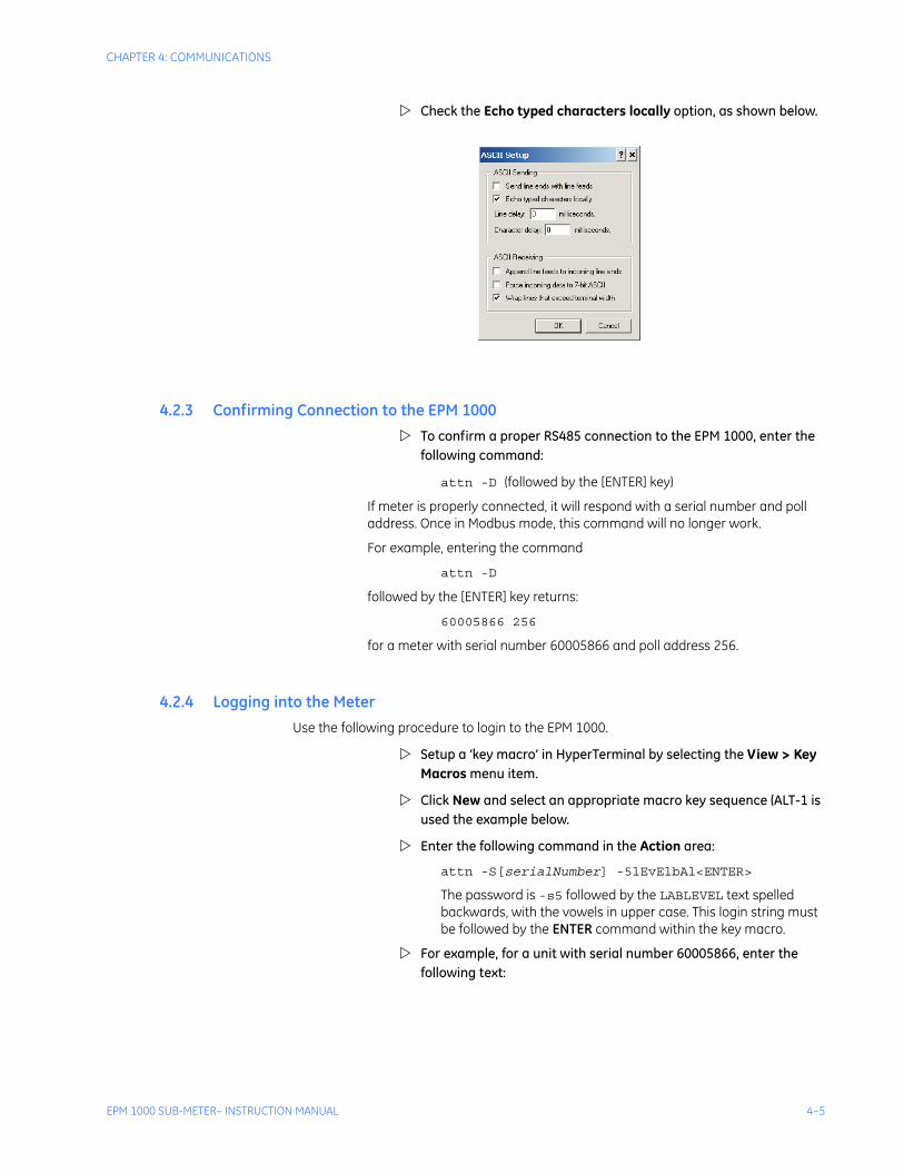
Check the Echo typed characters locally option, as shown below.
4.2.3 Confirming Connection to the EPM 1000To confirm a proper RS485 connection to the EPM 1000, enter the following command:
attn -D (followed by the [ENTER] key)
If meter is properly connected, it will respond with a serial number and poll address. Once in Modbus mode, this command will no longer work.
For example, entering the command
attn -D
followed by the [ENTER] key returns:
60005866 256
for a meter with serial number 60005866 and poll address 256.
4.2.4 Logging into the MeterUse the following procedure to login to the EPM 1000.
Setup a ‘key macro’ in HyperTerminal by selecting the View > Key Macros menu item.
Click New and select an appropriate macro key sequence (ALT-1 is used the example below.
Enter the following command in the Action area:
attn -S[serialNumber] -5lEvElbAl<ENTER>
The password is -s5 followed by the LABLEVEL text spelled backwards, with the vowels in upper case. This login string must be followed by the ENTER command within the key macro.
For example, for a unit with serial number 60005866, enter the following text:

4–6 EPM 1000 SUB-METER– INSTRUCTION MANUAL
CHAPTER 4: COMMUNICATIONS
4.2.5 Activating Modbus CommunicationsUse the following procedure to activate Modbus communications.
Enter the following command to activate Modbus:
stty -M1 (followed by [ENTER] twice)
Select the baud rate by entering the following command. The baud rate options for Modbus communication are 9600, 19200, and 38400.
stty 19200 (followed by [ENTER] twice)
Save Modbus activation by entering:
stty -W1234
Display Modbus activation by entering:
stty
This command displays meter port setting, baud rate, etc. If Modbus is active, it returns “Modbus”; if Modbus is not active, it returns “no Modbus”.
For example, consider the following set of commands sets the activates Modbus, sets the baud rate to 19200, and saves the Modbus activation. The text returned by the meter is also indicated.
CIP#sttyhunt 19200 baud 8 bits no parity no echo no modem no modbusCIP#stty -M1CIP#stty 19200CIP#stty -W1234CIP#sttyhold 19200 baud 8 bits no parity no echo no modem modbus

CHAPTER 4: COMMUNICATIONS
EPM 1000 SUB-METER– INSTRUCTION MANUAL 4–7
4.2.6 Changing Modbus SettingsUse the following procedure to change the Modbus address setting:
Enter the following command to set the Modbus address:
attn -p#
where # is replaced by the actual address desired (for example, attn -p100).
Save the Modbus address as follows
attn -W1234
Enter the following command to display and verify the Modbus address:
attn -d
This command displays the meter serial number and the poll/Modbus number.
4.2.7 Logging OutUse one of the following commands to logout of the meter:
attn or exit
Note Once Modbus is set, it is best to type [HALT] followed by [ENTER] or cycle power to the meter. Otherwise, Modbus will become active one minute after logout.
To log into meter once Modbus is active, use hot keys to program the login sequence. The login sequence must include either the serial number or the Modbus address.
Example hot key sequences are shown below:
attn -S60005866 -3Super3
attn 256 -3Super3
4.2.8 Disabling Modbus CommunicationsUse the following procedure to disable Modbus communications:
Turn off Modbus with the following command:
stty -M0
Save Modbus settings:
stty -W1234

4–8 EPM 1000 SUB-METER– INSTRUCTION MANUAL
CHAPTER 4: COMMUNICATIONS
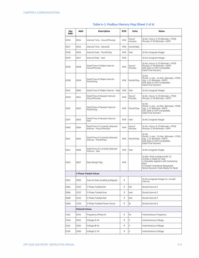
4.3 Modbus Memory Map
4.3.1 Memory MapThe Modbus memory map is shown below.
Table 4–1: Modbus Memory Map (Sheet 1 of 4)
Hex Addr
Addr Description R/W Units Notes
Fixed Value Registers (Read Only)
0000+ 0000 Meter Serial Number R 32-bit long integer
0002+ 0002 Meter Serial Number Extension R Returns same value as address 000032-bit long integer
0004+ 0004 Meter Version Number R 32-bit long integer
0006+ 0006 Meter Version Number Extension R Returns same value as address 000032-bit long integer
0008 0008 Meter Modbus Address R --- 8-bit Modbus Address in LSB
Setup Information
0009 0009 Baud Rate R
000C 0012 Meter Status R --- Always 1 for Modbus.
000D 0013 Meter Ready R --- Always 1 for Modbus.
000E 0014 Number of Meters Configured R --- Always 1 for EPM 1000
000F 0015 Number of Real-Time Points Configured R
0010 0016 Number of Interval Points Configured R Returns 0 if intervals are disabled
0011 0017 Number of Max/Min Points Configured R Always returns 0
0012 0018 Maximum Number of Intervals That Can Be Recorded R
Dependent upon the number of parameters optioned and the number of meters returned in address 0015
0013 0019 Number of slots configured for Transponder R
0014 0020 Current slot being read in Transponder R/W
Interval Setup
0031 0049 Store Interval Length R/W minutesInterval length in minutes must be evenly divisible into 60 (1, 2, 3, 4, 5, 6, 10, 12, 15, 20, 30, 60)
Read Clock
0032 0050 Internal Time - Hours/Minutes R/W hours/minutes
16-bit, Hours: 0-23 (bitmask = FF00)Minutes: 0-59 (bitmask = 00FF
0033 0051 Internal Time - Seconds R/W seconds
0034 0052 Internal Date - Month/Day R/W month/day
0035 0053 Interval Date - Year R/W year
CHAPTER 4: COMMUNICATIONS
EPM 1000 SUB-METER– INSTRUCTION MANUAL 4–9
0036 0054 Internal Time - Hours/Minutes R/W hours/minutes
16-bit, Hours: 0-23 (bitmask = FF00)Minutes: 0-59 (bitmask = 00FF
0037 0055 Internal Time - Seconds R/W month/day
0038 0056 Internal Date - Month/Day R/W Year 16-bit Unsigned Integer
0039 0057 Interval Date - Year R/W 16-bit Unsigned Integer
003A 0058 Date/Time of Oldest Interval - Hours/Minutes R/W Hours/
Minutes
16-bit, Hours: 0-23 (bitmask = FF00)Minutes: 0-59 (bitmask = 00FF)DDE Data is COM Compatible,Date/Time Numeric
003B 0059 Date/Time of Oldest Interval - Month/Day R/W Month/Day
16-bitMonth: 1=Jan., 12=Dec. (bitmask = FF00)Day: 1-31 (bitmask = 00FF)DDE Data is COM Compatible,Date/Time Numeric
003C 0060 Date/Time of Oldest Interval - Year R/W Year 16-bit Unsigned Integer
003D 0061 Date/Time of Newest Interval - Hours/Minutes R/W Hours/
Minutes16-bit, Hours: 0-23 (bitmask = FF00)Minutes: 0-59 (bitmask = 00FF)
003E 0062 Date/Time of Newest Interval - Month/Day R/W Month/Day
16-bitMonth: 1=Jan., 12=Dec. (bitmask = FF00)Day: 1-31 (bitmask = 00FF)DDE Data is COM Compatible,Date/Time Numeric
003F 0063 Date/Time of Newest Interval - Year R/W Year 16 Bit Unsigned Integer
0040 0064 Date/Time of Currently Selected Interval - Hours/Minutes R/W Hours/
Minutes16-bit, Hours: 0-23 (bitmask = FF00)Minutes: 0-59 (bitmask = 00FF
0041 0065 Date/Time of Currently Selected Interval - Month/Day R/W Month/Day
16-bitMonth: 1=Jan., 12=Dec. (bitmask = FF00)Day: 1-31 (bitmask = 00FF)DDE Data is COM Compatible,Date/Time Numeric
0042 0066 Date/Time of Currently Selected Interval - Year R/W Year 16 Bit Unsigned Integer
0043 0067 Data Ready Flag R/W
16 Bits: Mask out/ignore Bit 15.0=Data is ready for read1=Populate registers with timestamp data2=Invalid Timestamp RequestedStored Dynamic Data Ready for Read
3-Phase Totaled Values
0063 0099 Interval Data Qualifying Register R 16-bit Unsigned Integer, 8 = Invalid Interval
0064 0100 3-Phase Totaled kW R kW Stored Interval 1
0066 0102 3-Phase Totaled kvar R kvar Stored Interval 2
0068 0104 3-Phase Totaled kVA R kVA Stored Interval 3
006A 0106 3-Phase Totaled Power Factor R % Stored Interval 4
Metered Values
0162 0354 Frequency (Phase A) R Hz Instantaneous Frequency
016A 0362 Voltage (A-N) R V Instantaneous Voltage
016C 0364 Voltage (B-N) R V Instantaneous Voltage
016E 0366 Voltage (C-N) R V Instantaneous Voltage
Table 4–1: Modbus Memory Map (Sheet 2 of 4)
Hex Addr
Addr Description R/W Units Notes

4–10 EPM 1000 SUB-METER– INSTRUCTION MANUAL
CHAPTER 4: COMMUNICATIONS
0170* 0368 Voltage (CT01) R V Instantaneous Voltage
0172* 0370 Amps (CT01) R A Instantaneous Current
0174* 0372 kW (CT01) R kW Instantaneous Power
0176* 0374 kvar (CT01) R kvar Instantaneous Reactive Power
0178* 0376 kVA (CT01) R kVA Instantaneous Apparent Power
017A* 0378 Voltage (CT02) R V Instantaneous Voltage
017C* 0380 Amps (CT02) R A Instantaneous Current
017E* 0382 kW (CT02) R kW Instantaneous Power
0180* 0384 kvar (CT02) R kvar Instantaneous Reactive Power
0182* 0386 kVA (CT02) R kVA Instantaneous Apparent Power
0184* 0388 Voltage (CT03) R V Instantaneous Voltage
0186* 0390 Amps (CT03) R A Instantaneous Current
0188* 0392 kW (CT03) R kW Instantaneous Power
018A* 0394 kvar (CT03) R kvar Instantaneous Reactive Power
018C* 0396 kVA (CT03) R kVA Instantaneous Apparent Power
Three-Phase Metered Values
0288* 0648 3-Phase kWh R kWh Real Time Input 1
028A* 0650 3-Phase kvarh R kvarh Real Time Input 2
028C* 0652 3-Phase kW R kW Real Time Input 3
028E* 0654 3-Phase kvar R kvar Real Time Input 4
0290* 0656 3-Phase kVA R kVA Real Time Input 5
0292* 0658 3-Phase Power Factor R % Real Time Input 6
Total Harmonic Distortion (THD)
03E8* 1000 THD Phase A R % Total Harmonic Distortion
03EA* 1002 Phase Angle A R degrees Phase Angle
03EC* 1004 Phase-to-Phase Voltage A R V Instantaneous Voltage
03EE* 1006 THD Phase B R % Total Harmonic Distortion
03F0* 1008 Phase Angle B R degrees Phase Angle
03F2* 1010 Phase-to-Phase Voltage B R V Instantaneous Voltage
03F4* 1012 THD Phase C R % Total Harmonic Distortion
03F6* 1014 Phase Angle C R degrees Phase Angle
03F8* 1016 Phase-to-Phase Voltage C R V Instantaneous Voltage
Counters
07D0 2000 Number of phases offset 16-bit Unsigned Integer1, 2, 3, or 24 phases available
Table 4–1: Modbus Memory Map (Sheet 3 of 4)
Hex Addr
Addr Description R/W Units Notes

CHAPTER 4: COMMUNICATIONS
EPM 1000 SUB-METER– INSTRUCTION MANUAL 4–11
Note 1. 32-bit floating point numbers are as per the IEEE 754-1985 standard.
2. Registers 0X0063 to 0X025E are all read-only and cannot be modified. They break down as follows:
• Registers 0X0064 to 0X0122 are not real-time, but are populated with stored interval data based on user inputs to registers 0X0040 to 0X0043.
• Registers 0X0162 to 0X025E are all real-time data registers.
07D1 2001 Demand Window Offset 16-bit Unsigned Integer5, 15, or 30 minutes available
07D2 2002 I Multiplier Type Offset 16-bit Unsigned IntegerInternal calibration value
07D3 2003 Number of Pulse Counters Offset 16-bit Unsigned IntegerNumber of external pulse inputs installed
07D4 2004 Overlap Offset16-bit Unsigned IntegerNumber of adjacent demand windows that are averaged to determine peak demand
07D5 2005 Number TOU's Offset16-bit Unsigned IntegerNumber of different TOU periods defined in the time-of-use table
07D6 2006 MDT_M_TABLE_REG_START 16-bit Unsigned Integer
07D7 2007 NUM_MDT_M_TABLE_COLUMNS 16-bit Unsigned Integer
07D8 2008 NUM_MDT_M_TABLE_REGS 16-bit Unsigned Integer
07D9 2009 MDT_M_TABLE_REG_END 16-bit Unsigned Integer
* 32-bit floating point register.+ 32-bit long integer - Range: 00000000h to FFFFFFFFh
Table 4–1: Modbus Memory Map (Sheet 4 of 4)
Hex Addr
Addr Description R/W Units Notes

4–12 EPM 1000 SUB-METER– INSTRUCTION MANUAL
CHAPTER 4: COMMUNICATIONS

EPM 1000 SUB-METER – INSTRUCTION MANUAL 5–1
EPM 1000 Single Point Submetering System
Chapter 5: Miscellaneous
GE Consumer & IndustrialMultilin
Miscellaneous
5.1 Revision History
5.1.1 Release Dates
5.1.2 Changes to the Manual
Table 5–1: Release Dates
MANUAL GE PART NO. EPM 1000 REVISION
RELEASE DATE
GEK-106554 1601-0155-A1 1.0x 21 May 2004
GEK-106554A 1601-0155-A2 1.0x 20 October 2004
GEK-106554B 1601-0155-A3 1.0x 1 December 2004
GEK-106554C 1601-0155-A4 1.0x 14 February 2005
GEK-106554D 1601-0155-A5 1.0x 08 April 2005
GEK-106554E 1601-0155-A6 1.0x 30 June 2006
GEK-106554F 1601-0155-A7 1.0x 15 November 2007
Table 5–2: Major Updates for 1601-0155-A7 (Sheet 1 of 2)
PAGE(A6)
PAGE(A7)
CHANGE DESCRIPTION
Title Title Update Manual part number to 1601-0155-A7
5–2 EPM 1000 SUB-METER – INSTRUCTION MANUAL
CHAPTER 5: MISCELLANEOUS
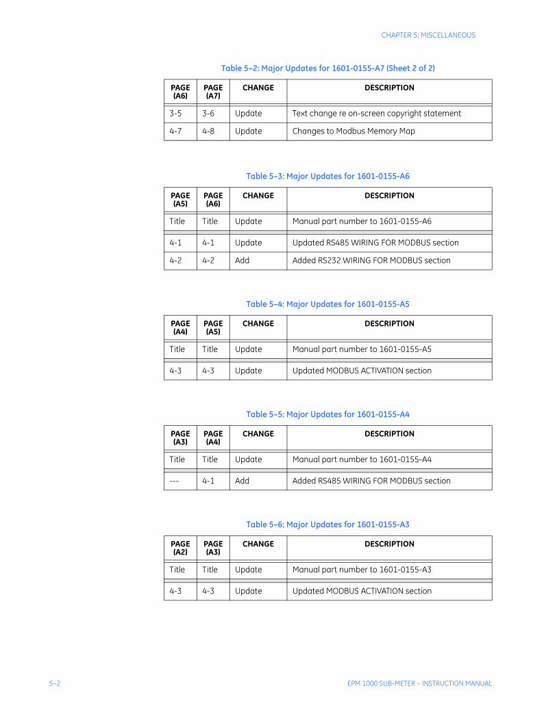
3-5 3-6 Update Text change re on-screen copyright statement
4-7 4-8 Update Changes to Modbus Memory Map
Table 5–3: Major Updates for 1601-0155-A6
PAGE(A5)
PAGE(A6)
CHANGE DESCRIPTION
Title Title Update Manual part number to 1601-0155-A6
4-1 4-1 Update Updated RS485 WIRING FOR MODBUS section
4-2 4-2 Add Added RS232 WIRING FOR MODBUS section
Table 5–4: Major Updates for 1601-0155-A5
PAGE(A4)
PAGE(A5)
CHANGE DESCRIPTION
Title Title Update Manual part number to 1601-0155-A5
4-3 4-3 Update Updated MODBUS ACTIVATION section
Table 5–5: Major Updates for 1601-0155-A4
PAGE(A3)
PAGE(A4)
CHANGE DESCRIPTION
Title Title Update Manual part number to 1601-0155-A4
--- 4-1 Add Added RS485 WIRING FOR MODBUS section
Table 5–6: Major Updates for 1601-0155-A3
PAGE(A2)
PAGE(A3)
CHANGE DESCRIPTION
Title Title Update Manual part number to 1601-0155-A3
4-3 4-3 Update Updated MODBUS ACTIVATION section
Table 5–2: Major Updates for 1601-0155-A7 (Sheet 2 of 2)
PAGE(A6)
PAGE(A7)
CHANGE DESCRIPTION

CHAPTER 5: MISCELLANEOUS
EPM 1000 SUB-METER – INSTRUCTION MANUAL 5–3
Table 5–7: Major Updates for 1601-0155-A2
PAGE(A1)
PAGE(A2)
CHANGE DESCRIPTION
Title Title Update Manual part number to 1601-0155-A2
1-3 1-3 Update Updated OPERATING SPECIFICATIONS
--- 2-7 Add Added CT TERMINATIONS FOR 1600 A AND 3200 A MODELS diagram
2-8 2-8 Update Updated INTERNAL SHORTING TERMINAL diagram and renamed to INTERNAL FUSE BLOCK
--- 4-1 Add Added MODBUS COMMUNICATIONS chapter

5–4 EPM 1000 SUB-METER – INSTRUCTION MANUAL
CHAPTER 5: MISCELLANEOUS
5.2 Warranty
5.2.1 GE Multilin WarrantyGeneral Electric Multilin (GE Multilin) warrants each device it manufactures to be free from defects in material and workmanship under normal use and service for a period of 24 months from date of shipment from factory.
In the event of a failure covered by warranty, GE Multilin will undertake to repair or replace the device providing the warrantor determined that it is defective and it is returned with all transportation charges prepaid to an authorized service centre or the factory. Repairs or replacement under warranty will be made without charge.
Warranty shall not apply to any device which has been subject to misuse, negligence, accident, incorrect installation or use not in accordance with instructions nor any unit that has been altered outside a GE Multilin authorized factory outlet.
GE Multilin is not liable for special, indirect or consequential damages or for loss of profit or for expenses sustained as a result of a device malfunction, incorrect application or adjustment.
For complete text of Warranty (including limitations and disclaimers), refer to GE Multilin Standard Conditions of Sale.

INDEX
EPM 1000 SUB-METER– INSTRUCTION MANUAL
Index
Index
A
APPLICATIONS ...............................................................................................1-2
B
CCATALOG NUMBERS ......................................................................................1-7CHANGES TO MANUAL ................................................................... 5-1, 5-2, 5-3COMMUNICATIONS
activating Modbus communications ................................................................4-6memory map .................................................................................................4-8Modbus .........................................................................................................4-2Modbus data groups ......................................................................................4-2
CT INSTALLATION ..........................................................................................2-9CT MULTIPLIERS ............................................................................................3-4CURRENT TRANSFORMER INSTALLATION ....................................................2-9CURRENT, VERIFYING ...................................................................................3-6
DDEMAND, RESETTING ....................................................................................3-7DESCRIPTION ................................................................................................1-1DIMENSIONS ..................................................................................................1-5DISPLAY STRUCTURE ....................................................................................3-3
EENERGY, VERIFYING .....................................................................................3-6ENVIRONMENTAL SPECIFICATIONS ..............................................................1-5
F
GGETTING STARTED ........................................................................................1-1
H
IINSTALLATION ....................................................................................... 2-1, 2-9INSTALLATION CATEGORY ............................................................................1-5INTERIOR VIEW..............................................................................................1-3INTERNAL FUSE BLOCK ............................................................................... 2-11

EPM 1000 SUB-METER– INSTRUCTION MANUAL
INDEX
J-L
MMENU NAVIGATION ....................................................................................... 3-1MENU STRUCTURE ....................................................................................... 3-3METER INSTALLATION .................................................................................. 2-9METERING SYSTEM REQUIREMENTS ........................................................... 2-1MODBUS
activating ..................................................................................................... 4-6commands.................................................................................................... 4-2data register groups ..................................................................................... 4-2memory map ................................................................................................ 4-8wiring ........................................................................................................... 4-1
N
OORDER CODES .............................................................................................. 1-7
PPOLLUTION DEGREE ..................................................................................... 1-5PREVENTIVE MAINTENANCE ........................................................................ 1-4PROTECTIVE CONDUCTOR TERMINAL ......................................................... 1-4PULSE INPUTS ............................................................................................ 2-12
Q
RRS232 WIRING FOR MODBUS........................................................................ 4-2RS485 WIRING FOR MODBUS........................................................................ 4-1
SSCAN TRANSPONDER
functionality .................................................................................................. 1-2installing .................................................................................................... 2-13location ...................................................................................................... 2-13
SPECIFICATIONS........................................................................................... 1-5
TTRANSIENT/SURGE SUPRESSION ................................................................ 1-5
UUSER INTERFACE ......................................................................................... 3-1

INDEX
EPM 1000 SUB-METER– INSTRUCTION MANUAL
VVERIFYING CURRENT ....................................................................................3-6VERIFYING ENERGY ......................................................................................3-6VERIFYING METER FUNCTIONALITY .............................................................3-5VERIFYING VOLTAGE.....................................................................................3-5VOLTAGE, VERIFYING....................................................................................3-5
WWARNINGS .....................................................................................................1-3WARRANTY ....................................................................................................5-4WIRING
1-phase, 3-wire center-tap-neutral .................................................................2-43-phase, 3-wire corner-grounded delta ...........................................................2-73-phase, 3-wire ungrounded delta ..................................................................2-63-phase, 4-wire center-tap-neutral delta .........................................................2-53-phase, 4-wire Wye .....................................................................................2-3diagrams.......................................................................................................2-2overview .......................................................................................................2-1
XYZ

EPM 1000 SUB-METER– INSTRUCTION MANUAL
INDEX


![Untitled-5 [] · 2020. 9. 15. · AMMETER EPM-4A 1 EPM-4C / EPM-4D / EPM-4P EPM-4D (Ammeter with Demand) : EPM-4D is designed to measure RMS value of AC current which flows from the](https://static.fdocuments.us/doc/165x107/60389b94586a40652f159b94/untitled-5-2020-9-15-ammeter-epm-4a-1-epm-4c-epm-4d-epm-4p-epm-4d-ammeter.jpg)