
Instruction Manual - ABS Engineering & Trading Sdn....
26
Instruction Manual ThinkTop ® Basic AS-Interface v.3.0 (62 nodes) 29.5 - 31.6 VDC TD 800-242_1 Patented Sensor System Registered Design Registered Trademark ESE01516-EN2 2011-01 Original manual
Transcript of Instruction Manual - ABS Engineering & Trading Sdn....
Instruction ManualThinkTop® Basic AS-Interface v.3.0 (62 nodes) 29.5 - 31.6 VDC
TD 800-242_1
Patented Sensor SystemRegistered DesignRegistered Trademark
ESE01516-EN2 2011-01
Original manual

Table of contents
The information herein is correct at the time of issue but may be subject to change without prior notice
1. EC Declaration of Conformity .. . . . . . . . . . . . . . . . . . . . . . . . . . . . . . . . . . . . . . . . . . . . . . . . . . . . . . . . . . . . . . . . . . . . . . 4
2. Safety .. . . . . . . . . . . . . . . . . . . . . . . . . . . . . . . . . . . . . . . . . . . . . . . . . . . . . . . . . . . . . . . . . . . . . . . . . . . . . . . . . . . . . . . . . . . . . . . . . . . 52.1. Important information ... . . . . . . . . . . . . . . . . . . . . . . . . . . . . . . . . . . . . . . . . . . . . . . . . . . . . . . . . . . . . . . . . . . . . . . . . . . 52.2. Warning signs ... . . . . . . . . . . . . . . . . . . . . . . . . . . . . . . . . . . . . . . . . . . . . . . . . . . . . . . . . . . . . . . . . . . . . . . . . . . . . . . . . . . 52.3. Safety precautions ... . . . . . . . . . . . . . . . . . . . . . . . . . . . . . . . . . . . . . . . . . . . . . . . . . . . . . . . . . . . . . . . . . . . . . . . . . . . . . 6
3. General information .. . . . . . . . . . . . . . . . . . . . . . . . . . . . . . . . . . . . . . . . . . . . . . . . . . . . . . . . . . . . . . . . . . . . . . . . . . . . . . . . . . 73.1. ThinkTop Basic AS-Interface in general . . . . . . . . . . . . . . . . . . . . . . . . . . . . . . . . . . . . . . . . . . . . . . . . . . . . . . . . . 7
4. Technical specifications .. . . . . . . . . . . . . . . . . . . . . . . . . . . . . . . . . . . . . . . . . . . . . . . . . . . . . . . . . . . . . . . . . . . . . . . . . . . . . 84.1. ThinkTop Basic AS-Interface ... . . . . . . . . . . . . . . . . . . . . . . . . . . . . . . . . . . . . . . . . . . . . . . . . . . . . . . . . . . . . . . . . . . 8
5. Installation .. . . . . . . . . . . . . . . . . . . . . . . . . . . . . . . . . . . . . . . . . . . . . . . . . . . . . . . . . . . . . . . . . . . . . . . . . . . . . . . . . . . . . . . . . . . . . 125.1. Installation on air actuators .. . . . . . . . . . . . . . . . . . . . . . . . . . . . . . . . . . . . . . . . . . . . . . . . . . . . . . . . . . . . . . . . . . . . . 125.2. Air connections .. . . . . . . . . . . . . . . . . . . . . . . . . . . . . . . . . . . . . . . . . . . . . . . . . . . . . . . . . . . . . . . . . . . . . . . . . . . . . . . . . . 155.3. Electrical connection, internal . . . . . . . . . . . . . . . . . . . . . . . . . . . . . . . . . . . . . . . . . . . . . . . . . . . . . . . . . . . . . . . . . . . 16
6. Setup diagram .... . . . . . . . . . . . . . . . . . . . . . . . . . . . . . . . . . . . . . . . . . . . . . . . . . . . . . . . . . . . . . . . . . . . . . . . . . . . . . . . . . . . . . 176.1. ThinkTop Basic AS-Interface setup ... . . . . . . . . . . . . . . . . . . . . . . . . . . . . . . . . . . . . . . . . . . . . . . . . . . . . . . . . . . 17
7. Maintenance ... . . . . . . . . . . . . . . . . . . . . . . . . . . . . . . . . . . . . . . . . . . . . . . . . . . . . . . . . . . . . . . . . . . . . . . . . . . . . . . . . . . . . . . . . 187.1. Dismantling of ThinkTop ... . . . . . . . . . . . . . . . . . . . . . . . . . . . . . . . . . . . . . . . . . . . . . . . . . . . . . . . . . . . . . . . . . . . . . . . 187.2. Assembly of ThinkTop ... . . . . . . . . . . . . . . . . . . . . . . . . . . . . . . . . . . . . . . . . . . . . . . . . . . . . . . . . . . . . . . . . . . . . . . . . . 20
8. Parts list and Service Kits .. . . . . . . . . . . . . . . . . . . . . . . . . . . . . . . . . . . . . . . . . . . . . . . . . . . . . . . . . . . . . . . . . . . . . . . . . . 238.1. Drawings for ThinkTop Basic AS-Interface ... . . . . . . . . . . . . . . . . . . . . . . . . . . . . . . . . . . . . . . . . . . . . . . . . . . 238.2. ThinkTop Basic AS-Interface ... . . . . . . . . . . . . . . . . . . . . . . . . . . . . . . . . . . . . . . . . . . . . . . . . . . . . . . . . . . . . . . . . . . 24
3

1 EC Declaration of Conformity
The designating company
Alfa LavalCompany Name
Albuen 31, DK-6000 Kolding, DenmarkAddress
+45 79 32 22 00Phone No.
hereby declare that
Top Unit for Valve Control & Indication ThinkTop Basic AS-InterfaceDenomination Type Year
is in conformity with the following directives with amendments:- Low Voltage Directive (LVD) 2006/95/EF- EMC Directive 2004/108/EF- ROHS Directive 2002/95/EEC
Manager, Product Centres, CompactHeat Exchangers & Fluid Handling
Bjarne Søndergaard
Title Name
Alfa Laval KoldingCompany Signature
Designation
4

2 Safety
Unsafe practices and other important information are emphasized in this manual.Warnings are emphasized by means of special signs. All warnings in the manual are summarized on this page.Pay special attention to the instructions below so that severe personal injury or damage to the top unit are avoided.
2.1 Important information
Always read the manual before using the top unit!
WARNINGIndicates that special procedures must be followed to avoid severe personal injury.
CAUTIONIndicates that special procedures must be followed to avoid damage to the ThinkTop Basic AS-Interface.
NOTEIndicates important information to simplify or clarify procedures.
2.2 Warning signs
General warning:
Dangerous electrical voltage:
Caustic agents:
5

2 Safety
Unsafe practices and other important information are emphasized in this manual.Warnings are emphasized by means of special signs. All warnings in the manual are summarized on this page.Pay special attention to the instructions below so that severe personal injury or damage to the top unit are avoided.
2.3 Safety precautions
Installation
Always read the technical data thoroughly.
Never install the ThinkTop Basic AS-Interface before valve or relay is in a safe position.
If welding close to the ThinkTop Basic AS-Interface: Always earth close to the welding area.
Disconnect the ThinkTop Basic AS-Interface.
Always have the ThinkTop Basic AS-Interface electrically connected by authorized personnel.
Maintenance
Always read the technical data thoroughly.
Always fit the seals between valve and ThinkTop Basic AS-Interface correctly.
Never install the ThinkTop Basic AS-Interface before valve or relay is in a safe position.
Never service the ThinkTop Basic AS-Interface with valve/actuator under pressure.
Never clean the ThinkTop Basic AS-Interface with high pressure cleaning equipment.
Never use cleaning agents when cleaning the ThinkTop Basic AS-Interface. Check with cleaningagent supplier.
6
3 General information
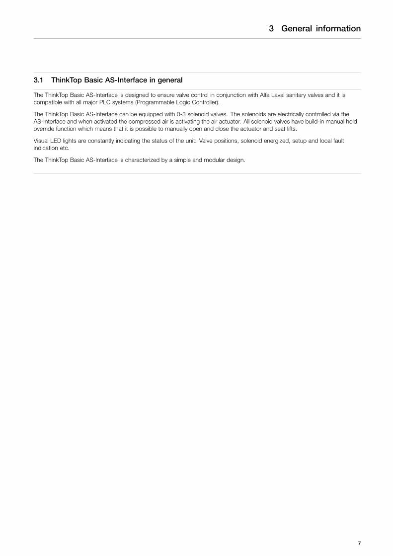
3.1 ThinkTop Basic AS-Interface in general
The ThinkTop Basic AS-Interface is designed to ensure valve control in conjunction with Alfa Laval sanitary valves and it iscompatible with all major PLC systems (Programmable Logic Controller).
The ThinkTop Basic AS-Interface can be equipped with 0-3 solenoid valves. The solenoids are electrically controlled via theAS-Interface and when activated the compressed air is activating the air actuator. All solenoid valves have build-in manual holdoverride function which means that it is possible to manually open and close the actuator and seat lifts.
Visual LED lights are constantly indicating the status of the unit: Valve positions, solenoid energized, setup and local faultindication etc.
The ThinkTop Basic AS-Interface is characterized by a simple and modular design.
7

4 Technical specifications
4.1 ThinkTop Basic AS-Interface
“No Touch” sensor system
21
3 45
6
87
911 10
1213
1617
181915 20
14
TD 800-267TD 800-267
1. Sensor board2. PLC, feedback3. Sensor unit4. PLC interface board5. N/A6. N/A7. Serial link8. LEDs9. +5 V10. Terminals
11. Terminals12. ASI +13. ASI -14. Bus Connection15. Internal connections16. Solenoid signals (DC)17. Solenoid common18. N/A19. N/A20. N/A
Type: Alfa Laval “No Touch” System. For wire connections: See 5.3 Electrical connection, internal“.
Features- Easy and simple set-up, using locally pushbottons.- No manual sensor adjustments at all.- No sensor "movements" due to vibrations.- Modular and hygienic design with exchangeabilities.- Clear LED’s for visual status indication.- Setup saved at power shutdown.
Sensor SystemUnique “No Touch” sensor system without any mechanical sensor adjustments. A magnet (indication pin) is mounted on thevalve stem and the magnetic field (axial) is detected by sensor chips inside the sensor unit. The measuring angle from eachchip is used to locate the current position of the valve stem with an accuracy of ± 0.1mm. Note that the distance to theindication pin can be 5 mm ± 3 mm.
Feedback signalsThe sensor system can be used for 2 feedback signals.
Electrical connectionDirect main cable gland entry (hard wired) PG11 (ø4 - ø10 mm).
TerminalsThe terminal row of the sensor board is equipped with screw terminals for both internal as well as external wires. The terminalsare suitable for wires up to 0.75 mm2 (AWG 19).
8

4 Technical specifications
Power SupplyThe power supply to the complete unit is taken from the AS-Interface loop. The unit is reverse polarity protected.
Supply voltage: . . . . . . . . . . . . . . . . . . . . . . 29.5 - 31.6 VDC
Typical power consumption ThinkTop Basic AS-InterfaceTest conditions = One ThinkTop Basic AS-Interface connected with 1 feedback active (on) and:
No solenoids on Supply voltage 24 VDC 30 mA1 solenoid active Supply voltage 24 VDC 75 mA2 solenoids active Supply voltage 24 VDC 120 mA3 solenoids active Supply voltage 24 VDC 165 mA
The fulfilling of the UL requirements in UL508 requires that the unit is supplied by an isolating source complying with therequirements for class 2 power units (UL1310) or class 2 and 3 transformers (UL1585).
Technical specifications sensor systemSensor accuracy: . . . . . . . . . . . . . . . . . . . ± 0.1 mm.Tolerance band: . . . . . . . . . . . . . . . . . . . . . ± 5 mm.Distance to indication pin: . . . . . . . . . . 5 ± 3 mm.Stroke length: . . . . . . . . . . . . . . . . . . . . . . . 0.1 - 80 mm.Electrical connection: . . . . . . . . . . . . . . . Direct cable gland entry
PG11 (ø4 - ø10 mm).
Slave profile v.3.0Default slave address: 0
IO code: 7 (4 bit bi-directional)ID code: AID1 code: 7ID2 code: 7Slave profile = 7.A.7.7
No. of slaves:AS-Interface specification 3.0 for max. 62 ThinkTop Basic AS-Interface units on a single master/gateway
AS-Interface bits assignment:For the AS-Interface version with 62 nodes, the following bit assignment will be used:
DI 0 . . . . . . . . . . . . . . . . . . . . . . . . . . . . . . . . . . Feedback # 1 De-Energized Position (closed position)DI 1 . . . . . . . . . . . . . . . . . . . . . . . . . . . . . . . . . . Feedback # 2 Energized Position (open position)DI 2 . . . . . . . . . . . . . . . . . . . . . . . . . . . . . . . . . . Feedback # 3 Not connectedDI 3 . . . . . . . . . . . . . . . . . . . . . . . . . . . . . . . . . . Feedback # 4 Status
DO 0 . . . . . . . . . . . . . . . . . . . . . . . . . . . . . . . . . Not connectedDO 1 . . . . . . . . . . . . . . . . . . . . . . . . . . . . . . . . . Solenoid valve 1DO 2 . . . . . . . . . . . . . . . . . . . . . . . . . . . . . . . . . Solenoid valve 2DO 3 . . . . . . . . . . . . . . . . . . . . . . . . . . . . . . . . . Solenoid valve 3
Status signal (Feedback # 4) input bit 3The status signal is used for two purposes:
- To indicate that the setup is ongoing (LED B).- To indicate an error condition (LED B). (Flashing LED = software error), (steady LED = hardware error).
9

4 Technical specifications
ThinkTop Basic AS-Interface Visual Indications LED Indications
LED A “Energized” (Yellow)
- -
LED B “Setup/Fault” (Red)
- -
LED C “Solenoid” (Yellow)
- -
TD 800-030_1
LED A
LED D
LED C
LED B
LED D “De-Energized" (Green)
Technical specifications solenoid valvesInternal connections
Terminals for wire connection of the solenoids mounted internally in the control head. The number of solenoids actually mountedin the control head could be 0 - 3.
Technical specifications
0 to 3 solenoid valves in each unit.Type 3/2 or 5/2 valve (only possible with one 5/2 valve)Air supply 300-900 kPa (3-9 bar)Filtered air, max. particles or dirt 5 μ 5-5 mg/m3
Max. flow 180 l/minMax. oil content 1 mg/m3
Max. water content 0.88 g/m3 -20 oC compressed airThroughput ø2.5 mmManual hold override. YesExternal air tube connection ø6 mm or 1/4” (specify when ordering)Silencer/filter Connection possible via ø6 mm or 1/4".
(Filter recommended in tropical regions)
Internal connections (solenoids)
The power consumption of the solenoids is being reduced via PWM (Pulse Width Modulation). The PWM can be disabled byremoving the jumper (terminal 3, 4)Nominal voltage 24 VDCNominal power 1.0 WLoad current Max. 100 mA per solenoid
Max. current from any number of energized output stagesis 200 mA
Voltage drop Max. 3 V at 50 mAActivation time 60 ± 10 ms (time with full power if PWM is enabled)PWM duty cycle 40% (after activation time if PWM is enabled)PWM frequency 2 - 5 kHz
Materials
Plastic parts Nylon PA6Steel parts Stainless steel AISI 304Seals Nitrile (NBR)Gore vent. membrane PBT plastic
10

4 Technical specifications
Micro environment demand specifications
TemperatureWorking: -20°C to +85°C IEC 68-2-1/2Storage: -40°C to +85°C IEC 68-2-1/2Temperature change: -25°C to +70°C IEC 68-2-14Vibration 10-55 Hz, 0.7 mm IEC 68-2-6
55-500 Hz, 10g3 x 30 min, 1 octave/min
Drop test IEC 68-2-32HumidityConstant humidity: +40°C, 21 days, 93% R.H. IEC 60068-2-78Cyclic humidity: +25°C/+55°C
12 cycles(working) 93% R.H.Protection class IP66 and IP67 IEC 60529Input tresholdVoltage/current: Type 1 input requirements EN 61131-2EMC Directive 2004/108/EF EN 61000-6-3, EN 61000-6-2AS-Interface Version 3.0*) EN50295UL/CSA 10-30 VDC, Class 2 input,
45 mA max. output UL 508-E203255
*) Max. 62 ThinkTop Basic AS-Interface units on a single master/gateway.
11

5 Installation
5.1 Installation on air actuators
Step 1
Always read the technical data thoroughly.
Always have the ThinkTop Basic AS-Interface electricallyconnected by authorized personnel.
Never install the ThinkTop Basic AS-Interface before valve or relayis in a safe position.
Step 21. Fit the air fittings on actuator if not mounted.2. Fit the indication pin and tighten carefully
with a spanner.
SRC only
Step 31. Place the ThinkTop Basic AS-Interface on top of the actuator.2. Make sure X-ring is mounted.
85
Step 41. Ensure that the unit is correctly mounted by pressing down on
top of the ThinkTop Basic AS-Interface.2. Tighten the two Allen screws carefully (1.50 Nm).3. Turn the actuator to have LEDs in a front view.
12

5 Installation
Step 5Fit the ø6 mm (1/4”) air tubes to ThinkTop Basic AS-Interface .(see drawing “Air connections” page 15).
Step 6Fit the air tubes to the actuator(see drawing “Air connections” page 15).
TD 800-131
Step 7Untighten the four screws and pull off cover of ThinkTop BasicAS-Interface.
TD 800-158
Step 81. Install cable (if not present) through the cable gland.2. Connect the ThinkTop Basic AS-Interface electrically
(see page 5.3 Electrical connection, internal).
TD 800-157
13
5 Installation
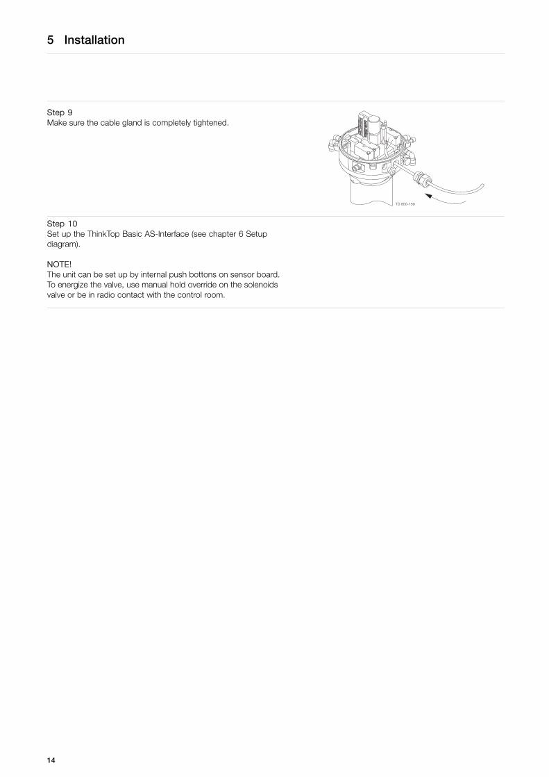
Step 9Make sure the cable gland is completely tightened.
TD 800-159
Step 10Set up the ThinkTop Basic AS-Interface (see chapter 6 Setupdiagram).
NOTE!The unit can be set up by internal push bottons on sensor board.To energize the valve, use manual hold override on the solenoidsvalve or be in radio contact with the control room.
14

5 Installation
5.2 Air connections
TD 800-184_1
A
B
C
D
E
F
G
H
I
A. Air out 1AB. Air exhaustC. Air out 1B (5/2 port solenoid valve only)D. Solenoid 3/2 or 5/2E. Solenoid valve (3/2) onlyF. Air inG. Air out 3H. Air out 2I. Manual hold override
15

5 Installation
5.3 Electrical connection, internal
TD 805-003
Electrical connections, internal
1. ASI +2. ASI -3. PWM jumper4. PWM jumper5. Solenoid common, internal connection (Brown)6. Solenoid # 1, internal connection (Blue)7. Solenoid # 2, internal connection (Blue)8. Solenoid # 3, internal connection (Blue)
Note! Remember to isolate wires that are not in use.
16
6 Setup diagram
6.1 ThinkTop Basic AS-Interface setup
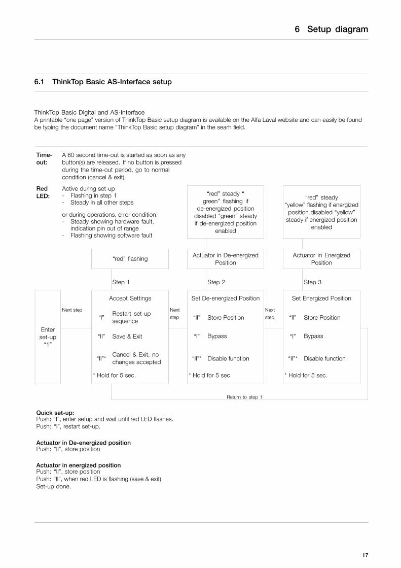
ThinkTop Basic Digital and AS-InterfaceA printable “one page” version of ThinkTop Basic setup diagram is available on the Alfa Laval website and can easily be foundbe typing the document name “ThinkTop Basic setup diagram” in the searh field.
Time-out:
A 60 second time-out is started as soon as anybutton(s) are released. If no button is pressedduring the time-out period, go to normalcondition (cancel & exit).
RedLED:
Active during set-up- Flashing in step 1- Steady in all other steps
or during operations, error condition:- Steady showing hardware fault,
indication pin out of range- Flashing showing software fault
“red” steady “green” flashing if
de-energized positiondisabled “green” steadyif de-energized position
enabled
“red” steady“yellow” flashing if energizedposition disabled “yellow”
steady if energized positionenabled
“red” flashing Actuator in De-energizedPosition
Actuator in EnergizedPosition
Step 1 Step 2 Step 3
Accept Settings Set De-energized Position Set Energized Position
Next step
“I”Restart set-upsequence
Next
step “II” Store PositionNext
step “II” Store Position
“II” Save & Exit “I” Bypass “I” Bypass
“II”*Cancel & Exit, nochanges accepted “II”* Disable function “II”* Disable function
Enterset-up
“1”
* Hold for 5 sec. * Hold for 5 sec. * Hold for 5 sec.
Return to step 1
Quick set-up:Push: “I”, enter setup and wait until red LED flashes.Push: “I”, restart set-up.
Actuator in De-energized positionPush: “II”, store position
Actuator in energized positionPush: “II”, store positionPush: “II”, when red LED is flashing (save & exit)Set-up done.
17
7 Maintenance
Study the instructions carefully.Handle scrap correctly.Always keep spare X-rings in stock.
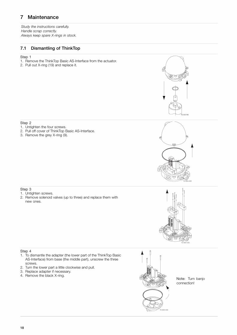
7.1 Dismantling of ThinkTop
Step 11. Remove the ThinkTop Basic AS-Interface from the actuator.2. Pull out X-ring (19) and replace it.
85
Step 21. Untighten the four screws.2. Pull off cover of ThinkTop Basic AS-Interface.3. Remove the grey X-ring (9).
TD 805-006
Step 31. Untighten screws.2. Remove solenoid valves (up to three) and replace them with
new ones.
TD 800-235
Step 41. To dismantle the adapter (the lower part of the ThinkTop Basic
AS-Interface) from base (the middle part), unscrew the threescrews.
2. Turn the lower part a little clockwise and pull.3. Replace adapter if necessary.4. Remove the black X-ring.
TD 800-230
Note: Turn banjoconnection!
18

7 Maintenance
Study the instructions carefully.Handle scrap correctly.Always keep spare X-rings in stock.
Step 5To remove the sensor unit untighten screw and pull outthe sensor unit.
TD 805-004
19

7 Maintenance
Study the instructions carefully.Handle scrap correctly.Always keep spare X-rings in stock.
7.2 Assembly of ThinkTop
Step 1Place sensor unit in base and tighten screw (torque: 1 Nm).
TD 805-005
Step 21. Replace the black X-ring.2. Assemble base with adapter by turning adapter slightly
anticlockwise and tighten the four screws (1.9 Nm).
CAUTION!Do NOT twist the X-ring in the groove!The X-ring is not square; The highest (h) partmust be placed as fig.
TD 800-233
Note:Turn banjoconnection!
Step 31. Replace solenoid valves (up to three) with new ones.2. Tighten screws (0.2 Nm).
TD 800-234
Step 41. Replace the grey X-ring.2. Replace cover of ThinkTop Basic AS-Interface and tighten
the four screws (0.6 Nm).
TD 805-007
20

7 Maintenance
Study the instructions carefully.Handle scrap correctly.Always keep spare X-rings in stock.
Step 51. Replace the black X-ring.2. Mount ThinkTop Basic AS-Interface on actuator.
85
21

.
22

8 Parts list and Service Kits
The drawings show ThinkTop Basic AS-Interface v.3.0 (62 nodes) 29.5 - 31.6 VDC.The items refer to the parts lists in the following sections
8.1 Drawings for ThinkTop Basic AS-Interface
TD 800-149
ø137 mm
H
W
171.
6 m
m
TD 805-002
5
9
8
16
15
1719
1
20
AS-Interface (+)
PWM Jumper/Diagnostic
AS-Interface (-)
Solenoid common
PWM Jumper/Diagnostic
Solenoid 1
Solenoid 2
Solenoid 3
Note! This is the basic design.Valve Type W H
Unique SSV NC 225 250SMP-SC/-BC/-TO 225 250Unique Mixproof 225 250MH 225 250SBV 225 250Unique SSV NO 225 320LKLA-T 225 300
TD 800-171
6b
6a
23

8 Parts list and Service Kits
The drawings show ThinkTop Basic AS-Interface v.3.0 (62 nodes) 29.5 - 31.6 VDC.The items refer to the parts lists in the following sections
8.2 ThinkTop Basic AS-Interface
TD 805-001
6b
6a
24

8 Parts list and Service Kits
The drawings show ThinkTop Basic AS-Interface v.3.0 (62 nodes) 29.5 - 31.6 VDC.The items refer to the parts lists in the following sections
Parts list
Pos. Qty Denomination
1 1 Shell complete3 1 Screw4 1 Washer5 1 Sensor board AS-Interface6a 1-3 Solenoid valves (3/2),6b 1 Solenoid valves (3/2 or 5/2),7 3 PT screw8 1 Base9 1 Special X-ring, grey10 1 Air fitting11 1 Blow-off valve12 1 Thread plug, PG7 ø3-ø6.5 mm13 1 Cable gland, PG11 ø4-ø10 mm14 1 Gore vent High airflow15 1 Adapter complete (Pos. 17,18,19
included)16 1 Special X-ring, black17 1 O-ring18 2 Allen screw19 1 Special X-ring20 1 Indication
Service kitsa Sensor board AS-Interface . . . . . . . . . . . . . . . . . . . . . . . . . . . . . . . . . . . . . 9613-4754-01a Solenoid valve 3/2, 24 VDC . . . . . . . . . . . . . . . . . . . . . . . . . . . . . . . . . . . . 9611-99-4635a Solenoid valve 5/2, 24 VDC . . . . . . . . . . . . . . . . . . . . . . . . . . . . . . . . . . . . 9611-99-3327a Indication pin . . . . . . . . . . . . . . . . . . . . . . . . . . . . . . . . . . . . . . . . . . . . . . . . . . . 9612-5623-01a Special indication pin, SRC-LS . . . . . . . . . . . . . . . . . . . . . . . . . . . . . . . . 9612-6370-01a Special indication pin, Unique SSV-LS: only stop valves size
63.5 - 101.6 mm/DN65-100 . . . . . . . . . . . . . . . . . . . . . . . . . . . . . . . . . . . 9613-1581-01a Special indication pin, Unique SSV High Pressure Valve size
76.1 - 101.6 mm/DN80-100 . . . . . . . . . . . . . . . . . . . . . . . . . . . . . . . . . . . 9613-1581-01a Air fitting, Ø6 mm . . . . . . . . . . . . . . . . . . . . . . . . . . . . . . . . . . . . . . . . . . . . . . 9611-99-3405a Air fitting, 1/4" . . . . . . . . . . . . . . . . . . . . . . . . . . . . . . . . . . . . . . . . . . . . . . . . . . 9611-99-3433a Gore vent . . . . . . . . . . . . . . . . . . . . . . . . . . . . . . . . . . . . . . . . . . . . . . . . . . . . . . 9611-99-4722a X-ring, pos. 9 . . . . . . . . . . . . . . . . . . . . . . . . . . . . . . . . . . . . . . . . . . . . . . . . . . 9613-4564-01a X-ring, pos. 16 . . . . . . . . . . . . . . . . . . . . . . . . . . . . . . . . . . . . . . . . . . . . . . . . . 9612-9994-01a X-ring, pos. 19 . . . . . . . . . . . . . . . . . . . . . . . . . . . . . . . . . . . . . . . . . . . . . . . . . 9612-5696-01
TD 900-565
25

How to contact Alfa LavalContact details for all countries arecontinually updated on our website.Please visit www.alfalaval.com to access the information direct.
© Alfa Laval Corporate ABThis document and its contents is owned by Alfa Laval Corporate AB and protected by laws governing intellectual property and thereto related rights. It is the responsibility of the user of thisdocument to comply with all applicable intellectual property laws. Without limiting any rights related to this document, no part of this document may be copied, reproduced or transmitted in anyform or by any means (electronic, mechanical, photocopying, recording, or otherwise), or for any purpose, without the expressed permission of Alfa Laval Corporate AB. Alfa Laval Corporate ABwill enforce its rights related to this document to the fullest extent of the law, including the seeking of criminal prosecution.


