Instruction Manual – ThinkTop® DeviceNet TM 11-25...
40
TD800100_3 The Top is identified by 4 fastening screws ESE00355-EN12 2013-07 Original manual Instruction Manual ThinkTop ® DeviceNet TM 11-25 VDC
Transcript of Instruction Manual – ThinkTop® DeviceNet TM 11-25...

TD800100_3
The Top is identified by 4 fastening screws
ESE00355-EN12 2013-07
Original manual
Instruction Manual
ThinkTop® DeviceNet TM 11-25 VDC


Table of contents
The information herein is correct at the time of issue but may be subject to change without prior notice
1. EC Declaration of Conformity .. . . . . . . . . . . . . . . . . . . . . . . . . . . . . . . . . . . . . . . . . . . . . . . . . . . . . . . . . . . . . . . . . . . . . . 4
2. Safety ... . . . . . . . . . . . . . . . . . . . . . . . . . . . . . . . . . . . . . . . . . . . . . . . . . . . . . . . . . . . . . . . . . . . . . . . . . . . . . . . . . . . . . . . . . . . . . . . . . 52.1. Important information .. . . . . . . . . . . . . . . . . . . . . . . . . . . . . . . . . . . . . . . . . . . . . . . . . . . . . . . . . . . . . . . . . . . . . . . . . . . . 52.2. Warning signs .. .. . . . . . . . . . . . . . . . . . . . . . . . . . . . . . . . . . . . . . . . . . . . . . . . . . . . . . . . . . . . . . . . . . . . . . . . . . . . . . . . . . 52.3. Safety precautions .. . .. . . . . . . . . . . . . . . . . . . . . . . . . . . . . . . . . . . . . . . . . . . . . . . . . . . . . . . . . . . . . . . . . . . . . . . . . . . . 6
3. General information .. . . . . . . . . . . . . . . . . . . . . . . . . . . . . . . . . . . . . . . . . . . . . . . . . . . . . . . . . . . . . . . . . . . . . . . . . . . . . . . . . . 73.1. DeviceNetTM in generel . . . . . . . . . . . . . . . . . . . . . . . . . . . . . . . . . . . . . . . . . . . . . . . . . . . . . . . . . . . . . . . . . . . . . . . . . . . 7
4. Technical specifications ... . . . . . . . . . . . . . . . . . . . . . . . . . . . . . . . . . . . . . . . . . . . . . . . . . . . . . . . . . . . . . . . . . . . . . . . . . . . 94.1. ThinkTop® DeviceNet TM features .. .. . . . . . . . . . . . . . . . . . . . . . . . . . . . . . . . . . . . . . . . . . . . . . . . . . . . . . . . . . . . 9
5. Installation .. . . . . . . . . . . . . . . . . . . . . . . . . . . . . . . . . . . . . . . . . . . . . . . . . . . . . . . . . . . . . . . . . . . . . . . . . . . . . . . . . . . . . . . . . . . . . 145.1. Installation on air actuators . . . . . . . . . . . . . . . . . . . . . . . . . . . . . . . . . . . . . . . . . . . . . . . . . . . . . . . . . . . . . . . . . . . . . . 145.2. Installation on Series 700 valves .. . .. . . . . . . . . . . . . . . . . . . . . . . . . . . . . . . . . . . . . . . . . . . . . . . . . . . . . . . . . . . . 175.3. Air connections .. . . . . . . . . . . . . . . . . . . . . . . . . . . . . . . . . . . . . . . . . . . . . . . . . . . . . . . . . . . . . . . . . . . . . . . . . . . . . . . . . . 185.4. Electrical connection, internal .. . . . . . . . . . . . . . . . . . . . . . . . . . . . . . . . . . . . . . . . . . . . . . . . . . . . . . . . . . . . . . . . . . 19
6. Setup diagram ... . . . . . . . . . . . . . . . . . . . . . . . . . . . . . . . . . . . . . . . . . . . . . . . . . . . . . . . . . . . . . . . . . . . . . . . . . . . . . . . . . . . . . . 206.1. ThinkTop® setup utilising IR keypad .. . . .. . . . . . . . . . . . . . . . . . . . . . . . . . . . . . . . . . . . . . . . . . . . . . . . . . . . . . . 206.2. ThinkTop® setup utilising local ’I’ and ’II’ keys .. . . . . . . . . . . . . . . . . . . . . . . . . . . . . . . . . . . . . . . . . . . . . . . . 226.3. ThinkTop® Quick setup guide ... . . . . . . . . . . . . . . . . . . . . . . . . . . . . . . . . . . . . . . . . . . . . . . . . . . . . . . . . . . . . . . . . 24
7. Troubleshooting .. . . . . . . . . . . . . . . . . . . . . . . . . . . . . . . . . . . . . . . . . . . . . . . . . . . . . . . . . . . . . . . . . . . . . . . . . . . . . . . . . . . . . . 267.1. Troubleshooting and LEDs .. . . . . . . . . . . . . . . . . . . . . . . . . . . . . . . . . . . . . . . . . . . . . . . . . . . . . . . . . . . . . . . . . . . . . . 267.2. ThinkTop® DeviceNetTM Error conditions and related response from the sensor board .. . 28
8. Maintenance .. . .. . . . . . . . . . . . . . . . . . . . . . . . . . . . . . . . . . . . . . . . . . . . . . . . . . . . . . . . . . . . . . . . . . . . . . . . . . . . . . . . . . . . . . . 298.1. Dismantling the ThinkTop® .. . . . . . . . . . . . . . . . . . . . . . . . . . . . . . . . . . . . . . . . . . . . . . . . . . . . . . . . . . . . . . . . . . . . . . 298.2. Assembling the ThinkTop® .. . . . . . . . . . . . . . . . . . . . . . . . . . . . . . . . . . . . . . . . . . . . . . . . . . . . . . . . . . . . . . . . . . . . . . 318.3. Dismantling and assembly of Series 700 valves .. .. . . . . . . . . . . . . . . . . . . . . . . . . . . . . . . . . . . . . . . . . . . . 33
9. Parts list and Service Kits .. . .. . . . . . . . . . . . . . . . . . . . . . . . . . . . . . . . . . . . . . . . . . . . . . . . . . . . . . . . . . . . . . . . . . . . . . . 349.1. Drawings for ThinkTop® DeviceNetTM 11-25 VDC ... . . . . . . . . . . . . . . . . . . . . . . . . . . . . . . . . . . . . . . . . . 349.2. ThinkTop® DeviceNetTM 11-25 VDC ... . .. . . . . . . . . . . . . . . . . . . . . . . . . . . . . . . . . . . . . . . . . . . . . . . . . . . . . . . 359.3. Drawings for ThinkTop® Series 700 Valves .. . .. . . . . . . . . . . . . . . . . . . . . . . . . . . . . . . . . . . . . . . . . . . . . . . . . 379.4. ThinkTop® Series 700 Valves .. .. . . . . . . . . . . . . . . . . . . . . . . . . . . . . . . . . . . . . . . . . . . . . . . . . . . . . . . . . . . . . . . . . 38
3

1 EC Declaration of Conformity
The designating company
Alfa LavalCompany Name
Albuen 31, DK-6000 Kolding, DenmarkAddress
+45 79 32 22 00Phone No.
hereby declares that
Top Unit for Valve Control & Indication ThinkTop®DeviceNetTM May 2012Denomination Type Year
is in conformity with the following directives with amendments:- Low Voltage Directive (LVD) 2006/95/EC- EMC Directive 2004/108/EC- ROHS Directive 2002/95/EEC
Manager, Product Centres,Compact Heat Exchangers & Fluid Handling
Bjarne Søndergaard
Title Name
Alfa Laval KoldingCompany Signature
Designation
4

2 Safety
Unsafe practices and other important information are highlighted in this manual.Warnings are highlighted by means of special signs. All warnings in the manual are summarised on this page.Pay special attention to the instructions below so that severe personal injury or damage to the top unit are avoided.
2.1 Important information
Always read the manual before using the top unit!
WARNINGIndicates that special procedures must be followed to avoid serious personal injury.
CAUTIONIndicates that special procedures must be followed to avoid damage to the ThinkTop®.
NOTEIndicates important information to simplify or clarify procedures.
2.2 Warning signs
General warning:
Dangerous electrical voltage:
Caustic agents:
5

2 Safety
Unsafe practices and other important information are highlighted in this manual.Warnings are highlighted by means of special signs. All warnings in the manual are summarised on this page.Pay special attention to the instructions below so that severe personal injury or damage to the top unit are avoided.
2.3 Safety precautions
Installation
Always read the technical data thoroughly.
Never install the ThinkTop® before valve or relay is in a safe position.
If welding close to the ThinkTop®: AAlways earth close to the welding area.
Disconnect the ThinkTop®.
Always have the ThinkTop® electrically connected by authorised personnel.
Maintenance
Always read the technical data thoroughly.
Always fit the seals between valve and ThinkTop® correctly.
Never service the ThinkTop® before valve or relay is in a safe position.
Never service the ThinkTop® with a valve/actuator under pressure.
Never clean the ThinkTop® with high-pressure cleaning equipment.
Never use cleaning agents when cleaning the ThinkTop®. Check with cleaning agent supplier.
6

3 General information
Unsafe practices and other important information are highlighted in this manual.Warnings are highlighted by means of special signs. All warnings in the manual are summarised on this page.Pay special attention to the instructions below so that severe personal injury or damage to the top unit are avoided.
3.1 DeviceNetTM in generel
DeviceNetTM is a low-cost communication link to connect industrial devices (such as limit switches, photoelectrical sensors, valvemanifolds, starter motors, process sensors, bar-code readers, variable frequency drives, display panels and operator interfaces)to a network and eliminate expensive handwiring. The direct connectivity provides improved communication between devices aswell as important device-level diagnostics not easily accessible or available through hardwired I/O interfaces. DeviceNetTM is asimple networking solution that reduces costs as well as time during the wiring and installation of industrial automation devices,while providing interchangeabillity of similar components from multiple vendors.
DeviceNetTM is an open network standard.
DeviceNetTM features and functionality
Network size Up to 63 nodesNetwork length Selectable end-to-end network distance varies with speed
Baud Rate125 Kbps250 Kbps500 Kbps
Distance500 (1,640 ft)250 (820 ft)100 (328 ft)
Data packets 0-8 bytesBus topology Linear (trunk line/drop line); power and signal on the same network cableBus addressing Peer-to-peer with multi-cast (one-to-many); multi-master and master/slave special case; polled or
change-of-state (exception-based)System features Removal and replacement of devices from the network under power
The basic trunk-line/drop-line topology provides separate twisted-pair busses for both signal and power distribution. Thick orthin cable can be used for either trunk lines or drop lines. End-to-end network distance varies with data rate and cable size.
Data rates 125 Kbps 250 Kbps 500 KbpsThick trunk length 500 m (1,640 ft) 250 m (820 ft) 100 m (328 ft)Thick trunk length 100 m (328 ft) 100 m (328 ft) 100 m (328 ft)Maximum drop length 6 m (20 ft) 6 m (20 ft) 6 m (20 ft)Cumulative drop length 156 m (512 ft) 78 m (256 ft) 39 m (128 ft)
The end-to-end network distance varies with data rate and cable thickness.
DeviceNetTM requires a terminating resistor to be installed at each end of the trunk:
- 121 ohm- 1% metal film- 1/4 Watt
Terminating resistors should not be installed at the end of a drop line, only at the two ends of the trunk-line.
For further information please see the DeviceNetTM Standard.
7

3 General information
Unsafe practices and other important information are highlighted in this manual.Warnings are highlighted by means of special signs. All warnings in the manual are summarised on this page.Pay special attention to the instructions below so that severe personal injury or damage to the top unit are avoided.
DeviceNetTM Features
Device type Generic Master/scanner NExplicit peer-to-peer messaging N I/O Slave messagingI/O peer-to-peer messaging N • Bit strobe NConfiguration consistency value N • Polling YFaulted node recovery N • Cyclic NBaud rates 125K, 250K, 500K • Change of state (COS) NConfiguration method EDS
The end-to-end network distance varies with data rate and cable thickness.
DeviceNetTM interfaceBaud rates: 125K, 250K and 500K.Polling I/O slave messaging.
Poll: 1 bytes.1 bytes = Input/outputs and alarms (class 4).
Node addressRange: 0-63.Default slave address: 63.
Power supplyThe power supply to the complete unit is taken from the DeviceNetTM.Supply voltage: 11-25 V DC, as specified for the DeviceNetTM.Supply current: Max. 45 mA (for sensor unit alone)
(excluding current to the solenoids and the external proximity switches).Electrical connection: Direct cable gland entry (hard-wired).
PG11 (ø4 - ø10 mm).PG7 (ø3 - ø6.5 mm) option, external sensor.
8

4 Technical specifications
Unsafe practices and other important information are highlighted in this manual.Warnings are highlighted by means of special signs. All warnings in the manual are summarised on this page.Pay special attention to the instructions below so that severe personal injury or damage to the top unit are avoided.
4.1 ThinkTop® DeviceNet TM features
“No Touch” sensor system
21
3 45
6
87
911 10
1213
1617
181915 20
14
TD 800-267TD 800-267
1. Sensor unit2. PLC, feedback3. Sensor board4. PLC interface board5. IR remote control6. IR Rx7. Serial link8. LEDs9. +5 V10. Terminals
11. Terminals12. ASI +13. ASI -14. Bus connection15. Internal connections16. Solenoid signals (DC)17. Solenoid common18. External seat-lift (PNP)19. Supply sensors20. External connections
Type: Alfa Laval “No Touch” System. For wiring connections: See 5.4 Electrical connection, internal“.
FFeatures- Tolerance programmes.- Self-adjustment programme (SRC/ARC valves only).- Built-in maintenance monitor.- Setup by internal push buttons or remote control (IR keypad).- Setup and local fault supervision.- Setup saved at power shutdown.- Visual LED indicator lights.
Sensor SystemUnique “No Touch” sensor system without any mechanical sensor adjustments. A magnet (indication pin) is mounted on thevalve stem and the magnetic field (axial) is detected by sensor chips inside the sensor board. The measuring angle from eachchip is used to locate the current position of the valve stem with an accuracy of ± 0.1mm. Note that the distance to theindication pin can be 5 mm ± 3 mm.
Feedback signalsInput signals (produced by the sensor unit) transmitted over the DeviceNetTM - class 4.Five feedback signals: Closed valve, open valve, seatlift 1, seatlift 2 and status.The status signal is used for five purposes:• To indicate that a setup is in progress (LED D).• To indicate an error condition (LED D), (flashing = software error), (steady = hardware error).• To indicate that maintenance is required (LED F).• To indicate if there is a conflict in the self adjustment programme (LED F).• To indicate if no communication exists between ThinkTop® and PLC (LED D, steady).
Tolerance programmeIndividual programme according to valve types.Type 0: Bypass valve type / keep present valve type.Type 1: SRC/ARC and Series 700 valves, only when self-adjustment is enabled - Not recommended.Type 2: LKB (LKLA-T).Type 3: Unique Mixproof, SMP-SC Spillage-Free and SRC-PV.Type 4: SMP-SC, SMP-TO, SMP-BC, SMP-BCA, SBV, SRC, ARC, Unique SSV, Unique SSV Aseptic, Unique-TO and Series
700 valves.Type 5: All parameters set to default (also valid for MH valve and SMP-EC (seat-lift indication not possible for SMP-EC)).
Preset and reset values: tolerance programme no./type 5 (± 5mm) and all functions are disabled.
Note! Important to select the right tolerance programme in order to ensure optimum controlled closure of valves.
9

4 Technical specifications
Unsafe practices and other important information are highlighted in this manual.Warnings are highlighted by means of special signs. All warnings in the manual are summarised on this page.Pay special attention to the instructions below so that severe personal injury or damage to the top unit are avoided.
Self-adjustment (SRC/ARC valves only)The self-adjustment feature is an exceptional aspect of the ThinkTop® design. A programme can be activated to allow anadjustment of the tolerance band if the seals in the valve are being compressed or are worn. When the tolerance band of theunit has been adjusted 0.3 mm, an alert warning will appear in the form of a status signal and a flashing maintenance LED.After 0.5 mm adjustment an alarm warning appears: loss of feedback signal, status signal and steady maintenance lightindicating a replacement of the seal.
Built-in maintenance monitorThe unit can be preset to indicate when the time for maintenance of the valve has been reached. A status signal and flashingmaintenance LED can be programmed to activate after 3, 6, 9 or 12 months or more.
Technical specificationsSensor system
Sensor accuracy: . . . . . . . . . . . . . . . . . . . . ± 0.1 mm.Distance to indication pin: . . . . . . . . . . 5 ± 3 mm.Stroke length: . . . . . . . . . . . . . . . . . . . . . . . 0.1 - 80 mm.
Electrical connection:Direct main cable gland entry (hard-wired) PG11 (ø4 - ø10 mm).
Direct external/sensor cable gland entry PG7 (ø3 - ø6.5 mm) option, external sensor.
TerminalsThe terminal row of the sensor unit is equipped with screw terminals for both internal as well as external cables and wires. Theterminals are suitable for wires up to 0.75 mm2 (AWG 19).
External sensorsThe external sensors are used for seat-lift supervision when seat-lift can not be internally detected. The sensors get their supplyvoltage from the terminal row. The output signals from the sensors are connected to two inputs on the terminal row on theinternal sensor unit. If the actual setup is set for internal seat-lift, the corresponding external signal is not used, otherwise theexternal signal logically controls the corresponding feedback to the PLC (Programmable Logic Controller).Note! If using external sensor, the sensor must be active/activated when performing a setup routine of the control head.
Supply voltage: . . . . . . . . . . . . . . . . . . . . . As specified for DeviceNetTM(typical 24VDC)Supply current: . . . . . . . . . . . . . . . . . . . . . . Max. 15 mA per sensor.Type of sensor: . . . . . . . . . . . . . . . . . . . . . . VDC, only 3-wire sensor, PNP.Cable length: . . . . . . . . . . . . . . . . . . . . . . . . Max. 3 m.
Alarm maskOutput signals received from the DeviceNetTM (consumed by the sensor unit).Four-bit mask to disable the alarm functions for the states “closed”, “open”, “seatlift 1” and “seatlift 2” respectively.
See also section 3.1.4 “ThinkTop® DeviceNetTM Attribute List”.
ThinkTop® visual indications LED indications
LED B “Open valve” (yellow)
O IR-receiver
LED D “Setup/Internal fault” (red)
LED C “Seat-lift 1/2” (yellow)
LED E “Solenoid valves” (green)
LED F “Maintenance” (orange)
LED B
LED D
LED C
LED E
LED F
LED A LED A “Closed valve” (yellow)
10

4 Technical specifications
Unsafe practices and other important information are highlighted in this manual.Warnings are highlighted by means of special signs. All warnings in the manual are summarised on this page.Pay special attention to the instructions below so that severe personal injury or damage to the top unit are avoided.
Note: If the programmer wishes to detect a physical closed valve position in an “Open Valve” sensor position, then there is nolonger any consistency between the sensor valve detection position and the visual indications on the ThinkTop®.
Technical specifications solenoid valvesSolenoid signals
Output signals received from the DeviceNet TM (consumed by the sensor unit) - class 4.
Three bits to control the solenoid drives located in the sensor unit.
Internal connections (solenoids)
The solenoid drivers are reducing the solenoid power by PWM after activation. The number of solenoids actually mountedin the control head could be 0 - 3.
Technical specifications
Up to 3 solenoid valves in each unit.Type 3/2 or 5/2 valve (only possible with one 5/2 valve).Air supply 300-900 kPa (3-9 bar).Filtered air, max. particles or dirt 5 μ 5-5 mg/m3.Max. flow 180 l/min.Max. oil content 1 mg/m3.Max. water content 0.88 g/m3 -20 oC compressed air.Throughput ø2.5 mm.Air restriction (throttle function) air inlet/outlet. Yes.Manual hold override. Yes.External air tube connection ø6 mm or 1/4” (specify when ordering).Silencer/filter Connection possible via ø6 mm or 1/4".
(Filter recommended in tropical regions).
Solenoids drive
Solenoid valve 8 VDC.O/P Voltage 8 VDC +/- 5%Power consumption 0.75W Max.Current consumption (per solenoid) 30mA Max.PWM Pull-in pulse length150ms Max. 150ms Max.PWM duty cycle 40% +/- 10%PWM frequency 2 kHz +/- 10%(PWM = Pulse width modulated)Note! Filter recommended in tropical regions.
Technical specifications aux. outputsThree aux. outputs can be used for external devices. The drivers are always NPN outputs and PWM mode is not possible. Thenumber of aux. outputs for activation of external devices can be 0-3. Clarification: all 3 outputs can be activated at the sametime but if solenoid 1 is in use, aux. 1 can not be used! If solenoid 1 and 2 are in use, aux. 1 and 2 can not be used! If solenoid1, 2 and 3 are in use, no aux. can be used! A mix of solenoid and aux. outputs is possible.
Output: NPN (sinking).Output voltage: 24 VDC ± 15%. Network power connection! User must ensure 24 VDC on the network (at the top) when
these outputs are used.Load current: Max 75 mA.
As these outputs drive constant current, using several nodes in this mode will reduce the number of nodessupported by a typical 8A network supply. The user must ensure that total network current consumptionis less than the supply rating.
11

4 Technical specifications
Unsafe practices and other important information are highlighted in this manual.Warnings are highlighted by means of special signs. All warnings in the manual are summarised on this page.Pay special attention to the instructions below so that severe personal injury or damage to the top unit are avoided.
ThinkTop®, EDS fileThe EDS file can be downloaded from www.alfalaval.com by searching "ThinkTop®" at the top of the main landing page. On theThinkTop® landing page choose Documentation in the menu and look for the EDS package. Alternatively the EDS file andfurther information on DeviceNetTM can found at www.odva.org
ThinkTop® DeviceNet TM attribute list
Path Raw dataName Attributes R/W/CS data
typelen. LSB
Release DNET 4.6 Class Inst dec. hex. “poll”Valve valueValve command
44
13
33
--
--
RR/W
ByteByte
11
--
ThinkTop® DeviceNetTM attribute list
Name Eng. Units Conv. Bit maps/datamult. divisor units byte 1 byte 2 byte 3 byte 4
Release DNET 4.6Valve valueValve command
--
--
--
PLC_imageSolenoids
--
--
--
ThinkTop® DeviceNetTM bit mappings
PLC_ImageValve value
x x x Maint. SL2 SL1 OPEN CLOSED
Solenoid 1,2 &3(Valve command)
x x x x Coil #3 Coil #2 Coil #1 x
ThinkTop® DeviceNetTM Poll command structures
Poll request message format
bitbyte 7 6 5 4 3 2 1 0
0 x x x xCoil #3
de-energizeCoil #2
de-energizeCoil #1
de-energizex
Poll response message format
bitbyte 7 6 5 4 3 2 1 0
0Travel inProgress
TimerExpired x
MAINT.ERROR
Seat #2Status
Seat #1Status
OPENStatus
CLOSEDStatus
12
4 Technical specifications
Unsafe practices and other important information are highlighted in this manual.Warnings are highlighted by means of special signs. All warnings in the manual are summarised on this page.Pay special attention to the instructions below so that severe personal injury or damage to the top unit are avoided.
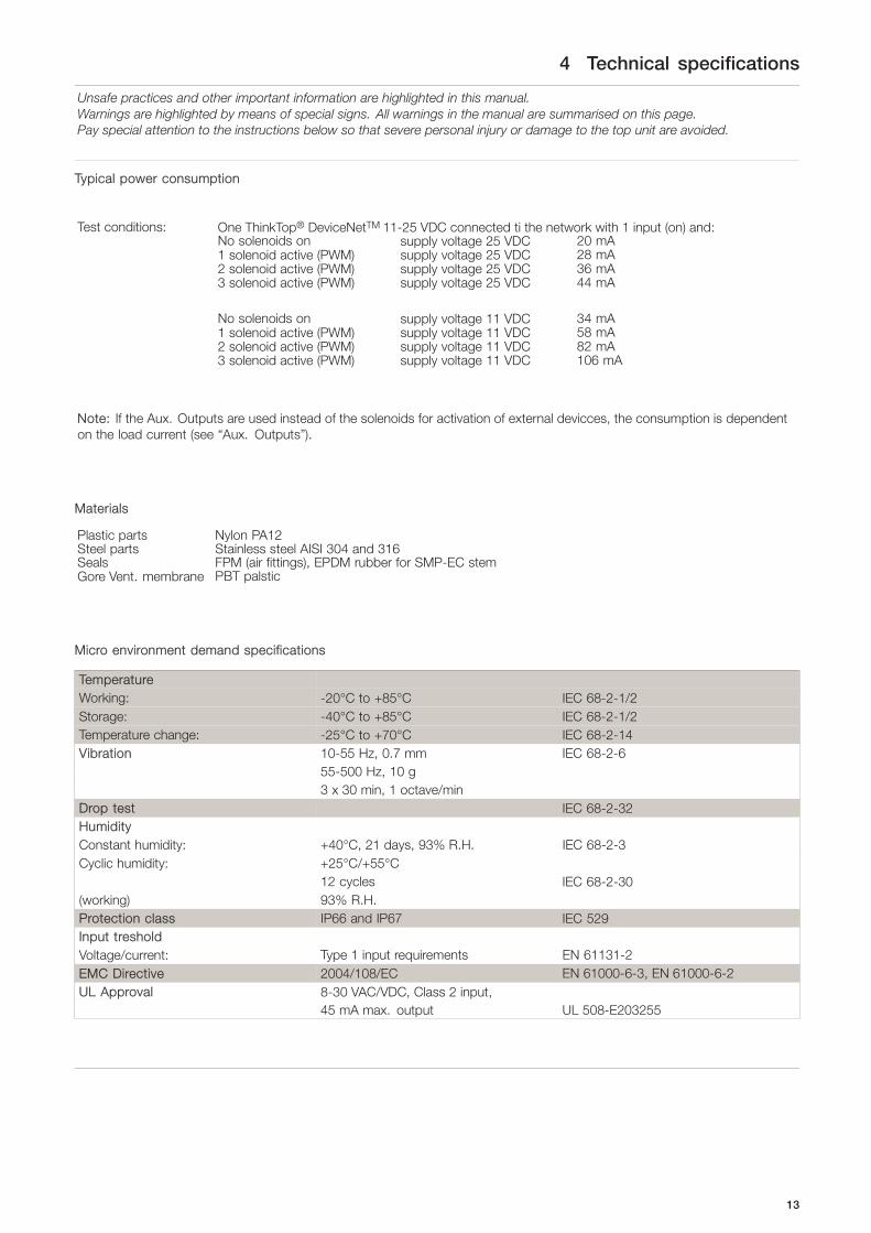
Typical power consumption
Test conditions: One ThinkTop® DeviceNetTM 11-25 VDC connected ti the network with 1 input (on) and:No solenoids on supply voltage 25 VDC 20 mA1 solenoid active (PWM) supply voltage 25 VDC 28 mA2 solenoid active (PWM) supply voltage 25 VDC 36 mA3 solenoid active (PWM) supply voltage 25 VDC 44 mA
No solenoids on supply voltage 11 VDC 34 mA1 solenoid active (PWM) supply voltage 11 VDC 58 mA2 solenoid active (PWM) supply voltage 11 VDC 82 mA3 solenoid active (PWM) supply voltage 11 VDC 106 mA
Note: If the Aux. Outputs are used instead of the solenoids for activation of external devicces, the consumption is dependenton the load current (see “Aux. Outputs”).
Materials
Plastic parts Nylon PA12Steel parts Stainless steel AISI 304 and 316Seals FPM (air fittings), EPDM rubber for SMP-EC stemGore Vent. membrane PBT palstic
Micro environment demand specifications
TemperatureWorking: -20°C to +85°C IEC 68-2-1/2Storage: -40°C to +85°C IEC 68-2-1/2Temperature change: -25°C to +70°C IEC 68-2-14Vibration 10-55 Hz, 0.7 mm IEC 68-2-6
55-500 Hz, 10 g3 x 30 min, 1 octave/min
Drop test IEC 68-2-32HumidityConstant humidity: +40°C, 21 days, 93% R.H. IEC 68-2-3Cyclic humidity: +25°C/+55°C
12 cycles IEC 68-2-30(working) 93% R.H.Protection class IP66 and IP67 IEC 529Input tresholdVoltage/current: Type 1 input requirements EN 61131-2EMC Directive 2004/108/EC EN 61000-6-3, EN 61000-6-2UL Approval 8-30 VAC/VDC, Class 2 input,
45 mA max. output UL 508-E203255
13

5 Installation
Unsafe practices and other important information are highlighted in this manual.Warnings are highlighted by means of special signs. All warnings in the manual are summarised on this page.Pay special attention to the instructions below so that severe personal injury or damage to the top unit are avoided.
5.1 Installation on air actuators
Step 1
Always read the technical data thoroughly.
Always have the ThinkTop® electrically connected by authorised personnel.
Step 21. Fit the air fittings on the actuator if not mounted.2. Fit the activator stem (magnet) and tighten ccarefully
with a spanner.
SRC only
SStep 31. Place the ThinkTop® on top of the actuator.2. Make sure X-ring is mounted.
85
SStep 41. Ensure that the unit is correctly mounted by ppressing down on
top of the ThinkTop®.2. Tighten the two Allen screws ccarefully (1.50 Nm).3. Turn the actuator to some LEDs are at the front.
14

5 Installation
Unsafe practices and other important information are highlighted in this manual.Warnings are highlighted by means of special signs. All warnings in the manual are summarised on this page.Pay special attention to the instructions below so that severe personal injury or damage to the top unit are avoided.
Step 5Fit the ø6 mm (1/4”) air tubes to the ThinkTop®.(see drawing “Air connections” page 18).
SStep 6Fit the air tubes to the actuator(see drawing “Air connections” page 18).
TD 800-131
SStep 7Loosen the four screws and pull off cover of the ThinkTop®.
2052-0003
SStep 81. Install cable (if not present) through the cable gland.2. Connect the ThinkTop® electrically
(see page 5.4 Electrical connection, internal).
2052-0004
15

5 Installation
Unsafe practices and other important information are highlighted in this manual.Warnings are highlighted by means of special signs. All warnings in the manual are summarised on this page.Pay special attention to the instructions below so that severe personal injury or damage to the top unit are avoided.
Step 9Make sure the cable gland is completely tightened.
2052-0005
SStep 10Set up the ThinkTop® (see chapter 6 Setup diagram).
NOTE!The unit can be set up with the cover installed by using the IRkeypad. To energise the valve, use a separate air tube or be inradio contact with the control room.
16

5 Installation
Unsafe practices and other important information are highlighted in this manual.Warnings are highlighted by means of special signs. All warnings in the manual are summarised on this page.Pay special attention to the instructions below so that severe personal injury or damage to the top unit are avoided.
5.2 Installation on Series 700 valves
Step 11. Remove the cover by loosening the four cover screws.2. Separate the adapter from the base by loosening the three
recessed screws on top of the base.
Installation on air actuators:
2052-0006
SStep 21. Fit air fittings onto the actuator.2. Position packing retainer in the recess on the actuator top.3. Fit the counter nut and indication pin (magnet) on actuator
rod. Engage approx. ¼” thread. Tighten the counter nut andindicator with two wrenches.
SStep 31. Place the two O-rings in the grooves in the bottom of the
adapter. Then place the adapter on the actuator top. The smallO-ring must be positioned over the air hole on the actuator.
2. Fasten the adapter with the four 5/16” Allen screws.
SStep 4Mount the base on the adapter in the position needed (can berotated 120° in both directions). Note that one of the screw towerson the adapter has a guide recess (see * on drawing).
2052-0007
17

5 Installation
Unsafe practices and other important information are highlighted in this manual.Warnings are highlighted by means of special signs. All warnings in the manual are summarised on this page.Pay special attention to the instructions below so that severe personal injury or damage to the top unit are avoided.
5.3 Air connections
1
2
3
A B
C
D
E
F
G
H
I
J
K
2052-0008
A. Air restriction (throttle function) air inlet/outletB. Air out 1AC. Air exhaustD. Air out 1B (5/2 port solenoid valve only)E. Solenoid 3/2 or 5/2F. 3/2 Solenoid valves onlyG. Air restriction (throttle function) air inlet/outletH. Air inI. Air out 3J. Air out 2K. Manual hold override
18

5 Installation
Unsafe practices and other important information are highlighted in this manual.Warnings are highlighted by means of special signs. All warnings in the manual are summarised on this page.Pay special attention to the instructions below so that severe personal injury or damage to the top unit are avoided.
5.4 Electrical connection, internal
Electrical connection
DeviceNetTM 63 node
Sensor board
Terminal strip
P2
P1 1 Power bus V- (Black)
N/C 6 2 CAN_L (Blue)
N/C 7 3 Drain (Bare)
N/C 8 4 CAN_H (White)
N/C 9 5 Power bus V+ (Red)
Bus cable
N/C 10 12 N/C
Not Connected
N/C 11 13 N/CNot connection
Earth Earth 24 Seat-lift 1 "upper"
Solenoid com.blue 20 25 Seat-lift 2 "lower"Signals from external sensors
Solenoid 1, brown 21 26 Supply +
Solenoid 2, brown 22 27 Supply-Power supply to external sensorsInternal connections
Solenoid 3, brown 23
19

6 Setup diagram
Unsafe practices and other important information are highlighted in this manual.Warnings are highlighted by means of special signs. All warnings in the manual are summarised on this page.Pay special attention to the instructions below so that severe personal injury or damage to the top unit are avoided.
6.1 ThinkTop® setup utilising IR keypad
General
Flashing LED means no value set. Steady LED means value set as shown.
Default: Step 2, factory-set tolerance band +/- 5 mmStep 3-8, disabled
D LED: Active during set-up: Flashing in step 1Steady in all other steps
Or during operations, error condition: Steady showing hardware fault, indication pin out of rangeFlashing showing software fault
Timeout: A 60 sec. timeout is started as soon as any button(s) are releasedOn timeout the setup is exited with no changes saved
IR Keypad: Remote distance 0-300 mm to ThinkTop®
Symbols
X Push key on IR keypad with the same number
Simple representation of LED indication:
Yellow BIR-ReciverRed D Steady LEDYellow CGreen EOrange FYellow A Flashing LED
GGeneral commands in each step (except step 1):
0 Next step / skip step (In step 3-6 the program automatically moves to the next stepwhen a position is stored)
5 Clear / disable step (In step 2 this resets the unit and sets the step 2-8 to default)(The command is accepted when all unit LED’s flash briefly)
IIt is recommended to reset the unit beforeperforming a setup.
Always check for correct signals after the setup.
20

6 Setup diagram
Unsafe practices and other important information are highlighted in this manual.Warnings are highlighted by means of special signs. All warnings in the manual are summarised on this page.Pay special attention to the instructions below so that severe personal injury or damage to the top unit are avoided.
0 Enter SetupStep 1 –
B1 Save and Exit
DNext C 2 Exit no change acceptedstep E
FA
SStep 2 – Setup valve typeB Default SRC/ARC LKB Unique Mixproof SMP-SC Unique 7000
+/- 5mm Series 700 (LKLA-T) SMP-SC SF SMP-BC Unique Mixproof PMO/CurdD (OOnly used SRC-PV SMP-TO Unique Mixproof CP3/LP
Next C when self AMP SMP-BCA Unique Mixproof HT/VT Reset unitstep E adjustment SBV Unique Mixproof 3A
F 1 feature is 2 3 4 Unique SSV 5
A required) SRC/ARCSeries 700
SStep 3 – Set closed positionB Default Position stored.
D CleatNext C positionstep E
F
Activate the valve to the close position
(De-energized) 1auto
5
A
SStep 4 – Set open positionB Default Position stored
ClearNext D positionstep C
E1
auto5
F
Activate the valve to the open position
(Energized)
SStep 5 – Set upper seat lift.B Default Position stored
Next D Clearstep C position
EF
Activate the valve to upper seat lift. When
using an external sensor the sensor must
be active when ”1” is pushed1
auto5
A
SStep 6 – Set lower seat lift.B Default Position stored.
Next Clearstep D position
CE 5F
Activate the valve to lower seat lift. When
using an external sensor the sensor must
be active when ”1” is pushed autoA
SStep 7 – Set self adjust (Recommended: Disabled)B Default Associated Associated Associated
Next Disabled with with withstep D closed/ closed open Disable
C open position position functionE positionF 1 2 3 5
A
SStep 8 – Setup maintenanceB Default 90 days 180 days 270 days 360 days
DisabledNext D Disablestep C function
EF 1 2 3 4 5
0
0
0
0
0
0
0
0
A
21

6 Setup diagram
Unsafe practices and other important information are highlighted in this manual.Warnings are highlighted by means of special signs. All warnings in the manual are summarised on this page.Pay special attention to the instructions below so that severe personal injury or damage to the top unit are avoided.
6.2 ThinkTop® setup utilising local ’I’ and ’II’ keys
General
Default is: Step 2, tolerance is +/- 5 mmStep 3-8, disabled
Timeout: A 60 sec. timeout is started as soon as any button(s) is released.On timeout the setup is exited with no changes saved.
Flashing LED means no value set. Steady LED means value set as shown[D] LED: Active during set-up: Flashing in step 1
Steady in all other steps
Or during operations, error condition: Steady showing hardware fault, indication pin out of rangeFlashing showing software fault
General commands in each step (except step 1):
5s Next step / skip step (In step 3-6 the program automatically moves to the next stepwhen a position is stored)
5s Clear / disable step (In step 2 this resets the unit to default)(The command is accepted when all unlit LED’s flash briefly)
IIt is recommended to reset the unit before performing a setup.
Symbols
5s Push local key “I”
5s Push local key “II”
5s
Hold key “II” for 5 sec
Simple representation of LED indication:
Yellow BIR-ReciverRed D Steady LEDYellow CGreen EOrange FYellow A Flashing LED
22

6 Setup diagram
Unsafe practices and other important information are highlighted in this manual.Warnings are highlighted by means of special signs. All warnings in the manual are summarised on this page.Pay special attention to the instructions below so that severe personal injury or damage to the top unit are avoided.
Enter SetupStep 1 –
B5s Save and Exit
DNextC 5s Exit no change acceptedstep E
FA
Step 2 – Setup valve typeB Default SRC/ARC LKB Unique Mixproof SMP-SC Unique 7000
+/- 5mm Series 700 (LKLA-T) SMP-SC SMP-BC Unique Mixproof PMO/CurdD (OOnly used SRC-PV SMP-TO Unique Mixproof CP3/LP
NextC when self AMP SMP-BCA Unique Mixproof HT/VTstep E adjustment SBV Unique Mixproof 3A
F feature is Unique SSVA required) SRC/ARC
Next Series 700step
SStep 3 – Set closed positionB Default Position stored
DNextCstep E
F
Activate the valve to the closed position
(De-energized)auto
A
SStep 4 – Set open positionB Default Position stored
NextDstep C
E autoF
Activate the valve to the open position
(Energized)
SStep 5 – Set upper seat liftB Default Position stored
NextDstep C
EF
Activate the valve to upper seat lift. When
using an external sensor the sensor must
be active when ””II” is pushed autoA
SStep 6 – Set lower seat liftB Default Position stored
DNextCstep E
F
Activate the valve to lower seat lift. When
using an external sensor the sensor must
be active when ””II” is pushed autoA
SStep 7 – Set self adjust (Recommended: Disabled)B Default Associated Associated Associated
Disabled with with withNextD closed/ closed openstep C open position position
E positionFA Next
step
SStep 8 – Setup maintenanceB Default 90 days 180 days 270 days 360 days +90 days
Disabled (Up toNextD max.step C 18 years)
EFA Next
step
23

6 Setup diagram
Unsafe practices and other important information are highlighted in this manual.Warnings are highlighted by means of special signs. All warnings in the manual are summarised on this page.Pay special attention to the instructions below so that severe personal injury or damage to the top unit are avoided.
6.3 ThinkTop® Quick setup guide
Valve: Unique SSV, SRC/ARC type NC (self-adjustment disabled)Push: I - and wait until red LED flashesPush: IPush: II - hold for 5 sec (clear all stored parameters)Push: II (red + yellow LED)Push: II (red + yellow + green LED)Push: II (red + yellow + green + orange LED)Push: II (red + yellow + green + orange + yellow LED)Push: IPush: II - to approve valve down (closed)
Activate valve opensPush: II - to approve (open)Push: I (no upper seat-lift)Push: I (no lower seat-lift)Push: I (no self-adjustment)Push: I (no maintenance)Push: II red LED flashes (save & exit by push)
Setupdone
Valve: SRC/ARC type NO (self-adjustment enabled)Push: I - and wait until red LED flashesPush: IPush: II - hold for 5 sec (clear all stored parameters)Push: II (red + yellow LED)Push: I
Activate valve closesPush: II - to approve valve closedPush: Deactivate valve opensPush: II - to approve valve is openPush: I (no upper seat-lift)Push: I (no lower seat-lift)Push: II = self-adjustmentPush: IPush: I (no maintenance)Push: II red LED flashes (save & exit by push)
Setupdone
Valve: LKB Valve (Butterfly) NCPush: I - and wait until red LED flashesPush: IPush: II - hold for 5 secPush: II (red + yellow LED)Push: II (red + yellow + green LED)
IPush: II - to approve valve closed (indication-stem up)Push: Activate LKB valve- open position (indication-stem down)Push: II - to approve valve is openPush: I (no upper seat-lift)Push: I (no lower seat-lift)Push: I (no self-adjustment)Push: I (no maintenance)Push: II red LED flashes (save & exit by push)
Setupdone
24

6 Setup diagram
Unsafe practices and other important information are highlighted in this manual.Warnings are highlighted by means of special signs. All warnings in the manual are summarised on this page.Pay special attention to the instructions below so that severe personal injury or damage to the top unit are avoided.
Valve: LKB Valve (Butterfly) NO
Push: I - and wait until red LED flashesPush: IPush: II - hold for 5 sec (clear all stored parameters)Push: II (red + yellow LED)Push: II (red + yellow + green LED)Push: I
Activate - to approve valve closed (indication-stem up)Push: II - to approve valve closedPush: Deactivate LKB valve-open position (indication-stem up)Push: II - to approve valve is openPush: I (no upper seat-lift)Push: I (no lower seat-lift)Push: I (no self-adjustment)Push: I (no maintenance)Push: II red LED flashes (save & exit by push)
Setupdone
Valve: Unique Mixproof Valve (with lower seat-lift)Push: I - and wait until red LED flashesPush: IPush: II - hold for 5 sec (clear all stored parameters)Push: II (red + yellow LED)Push: II (red + yellow + green LED)Push: II (red + yellow + green + orange LED)
IPush: II - to approve valve closed
Activate valve opensPush: II - to approve valve is openPush: I (no upper seat-lift)Push: Activate lower seat-lift activePush: II - to approvePush: I (no self-adjustment)Push: I (no maintenance)Push: II red LED flashes (save & exit by push)
Setupdone
25

7 Troubleshooting
Unsafe practices and other important information are highlighted in this manual.Warnings are highlighted by means of special signs. All warnings in the manual are summarised on this page.Pay special attention to the instructions below so that severe personal injury or damage to the top unit are avoided.
7.1 Troubleshooting and LEDs
Below are the meanings of the LEDs’ indications for troubleshooting in connection with the operation of the ThinkTop®.
7.1.1 Status LED (red)
Red flashing: Unit in set-up mode or internal software fault. If internal software fault, re-programme unit.
Red Red steady: Unit in set-up mode or internal hardware fault. If internal hardware fault, check if magnet isin range and check correct wiring.
Red steady:
7.1.2 Maintenance time out
Yellow B 1.Orange flashing: Time for maintenance has run out. The unit has been self-adjusted into a maintenancealert condition. Valve maintenance is strongly recommended. After maintenance: disablingof maintenance/self-adjustment function is required before setting new position. However,it is strongly recommended to perform a complete new set-up after valve maintenance.
Orange
Yellow A 2.Orange steady,yellow flashing(A and/or B):
The unit has been self-adjusted into a maintenance alarm condition and the feedback islost (a minimum of seal left). Valve maintenance is required. After maintenance: disablingof the self-adjustment function is required before setting new position. However, it isstrongly recommended to perform a complete new set-up after valve maintenance.
NOTE! The maintenance indicator lights up and an open or closed light flashes..... = Notethe following:- Self-adjustment programme is only valid for SRC/ARC valves: do not use the
programme for other valve types.- Use tolerance/valve type 1.- In conjunction with valve type change-over, 21, 22, 31 and 32, the open position must
be defined as the upper sensor position (when the indication pin is in the highestposition).
- A loose top, indication pin or sensor system can also generate the alert/alarm condition.- Removing the ThinkTop® with self-adjust activated, will immediately generate an alarm
condition! If the ThinkTop® has to be removed, not because of a valve maintenanceissue, but for some other reasons, and you want to store the already adjusted data,disable the self-adjust function before removing the ThinkTop and enable it againonce the ThinkTop® is back on the actuator.
- After valve maintenance disabling of the self-adjustment function is required beforesetting a new position, however, it is strongly recommended to perform a complete newset-up (disable all functions in step 2 valve type - and make a complete new set-up).
26

7 Troubleshooting
Unsafe practices and other important information are highlighted in this manual.Warnings are highlighted by means of special signs. All warnings in the manual are summarised on this page.Pay special attention to the instructions below so that severe personal injury or damage to the top unit are avoided.
7.2 LED indication during normal operation
Yellow A Yellow steady: Position A (closed valve).
Yellow B Yellow steady: Position B (open valve).
Yellow C Yellow steady: Position C (Seat-lift 1-2 or external sensors).
Green Green steady: Solenoid valves energised.
NNote! During set-up LED lights have different functions.
27

7 Troubleshooting
Unsafe practices and other important information are highlighted in this manual.Warnings are highlighted by means of special signs. All warnings in the manual are summarised on this page.Pay special attention to the instructions below so that severe personal injury or damage to the top unit are avoided.
7.2 ThinkTop® DeviceNetTM Error conditions and related response from the sensor board
The following tables shows the error conditions and related responses for the upgraded sensor boards related to the previoussensor boards.
If the DeviceNetTMcommunication is lost the sensor board goes into fail-safe condition and deactivates all solenoid valve signals.
Upgraded Sensor board time-outs, Rev 02.003 (From June 2012)
Error Condition Delay Recoverable error Status feedbackTurn key on PLC 10 msec Yes NoBUSOFF 10 msec No YesTIMED OUT 60 s Yes No
Previous Sensor board time-out, Rev 70.073 (Before June 2012)
Error Condition Delay Recoverable error Status feedbackTurn key on PLC 10 msec Yes YesBUSOFF 10 msec No YesTIMED OUT 10 msec Yes Yes
Error Condition - Turn key on PLC: - From Run to Progm. (Scanner mode: Idle)A Master device implicitly transmits its current operating mode with every I/O scan. If the Master device (typically a ProgrammableController) is in a non-run mode the Master produces an I/O message with zero data bytes known as an IDLE mode message.
Error Condition - BUSOFF:In the BusOff state the device has detected significant network errors and has removed itself from network operation.
Error Condition - TIMED OUT:Messages have failed to arrive on one or more connections with the Master device.
Delay:The time from when the communication is lost until the sensor board goes into fail-safe mode.
Recoverable error:A sensor board in a recoverable error condition will return to operation when communication is restored. Otherwise a powerrecycle is necessary.
Status feedback:Status feedback is represented by a red LED on the sensor board.
28

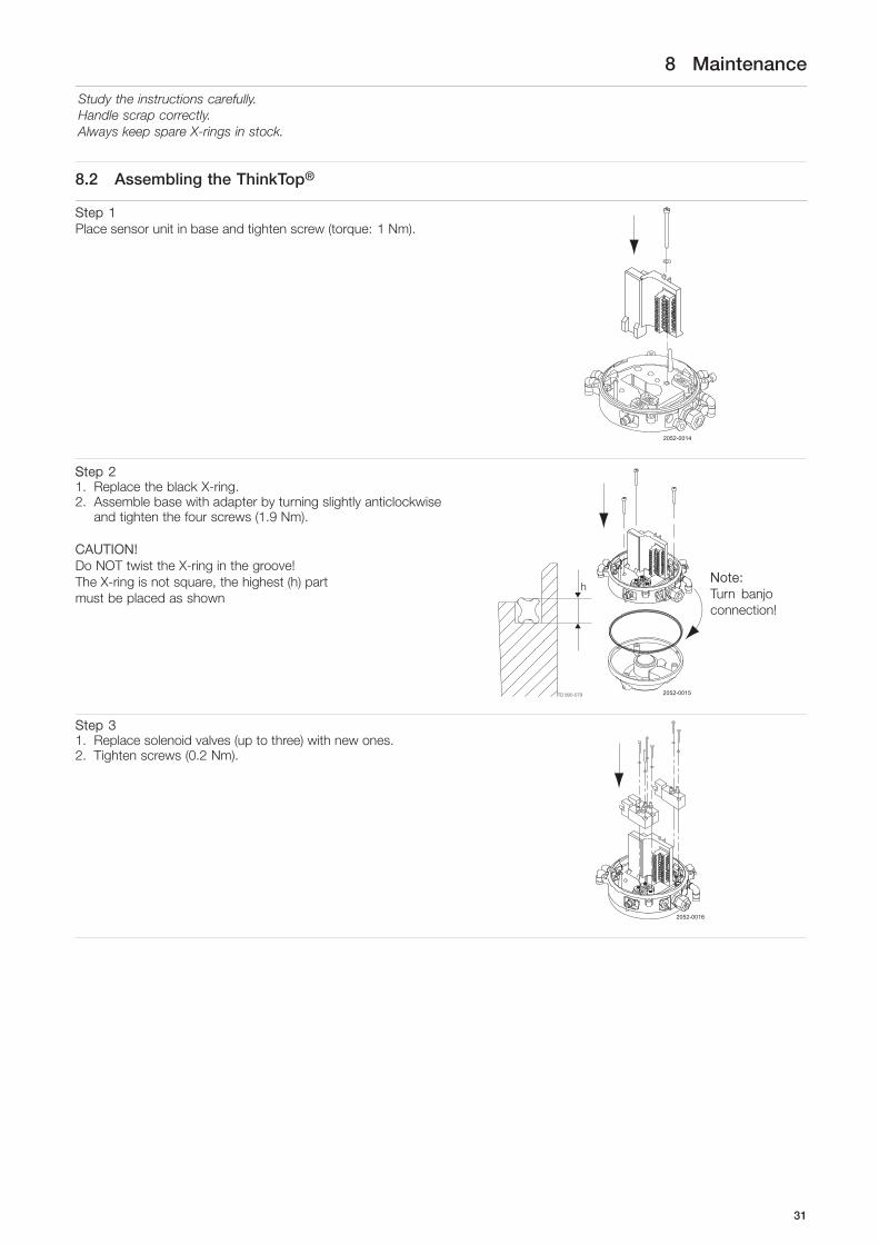
8 Maintenance
Study the instructions carefully.Handle scrap correctly.Always keep spare X-rings in stock.
8.1 Dismantling the ThinkTop®
Step 11. Loosen the two Allen screws and remove the ThinkTop® from
the actuator.2. Pull out the X-ring (19) and replace it.
85
SStep 21. Loosen the four screws.2. Pull off the cover of the ThinkTop®.3. Remove the X-ring (9) (grey).
2052-0010
SStep 31. Loosen screws.2. Remove the solenoid valves (up to three) and replace them
with new ones.
2052-0011
29

8 Maintenance
Study the instructions carefully.Handle scrap correctly.Always keep spare X-rings in stock.
Step 41. To dismantle the adapter (the lower part of the ThinkTop®) from
base (the middle part), undo the three screws.2. Turn the lower part slightly clockwise and pull.3. Replace adapter if necessary.4. Remove the black X-ring.
2052-0012
NNote: Turn banjoconnection!
Step 5To remove the sensor unit loosen the screw and pull outthe sensor unit.
2052-0013
30
8 Maintenance
Study the instructions carefully.Handle scrap correctly.Always keep spare X-rings in stock.
8.2 Assembling the ThinkTop®
Step 1Place sensor unit in base and tighten screw (torque: 1 Nm).
2052-0014
SStep 21. Replace the black X-ring.2. Assemble base with adapter by turning slightly anticlockwise
and tighten the four screws (1.9 Nm).
CAUTION!Do NOT twist the X-ring in the groove!The X-ring is not square, the highest (h) partmust be placed as shown
2052-0015
NNote:Turn banjoconnection!
Step 31. Replace solenoid valves (up to three) with new ones.2. Tighten screws (0.2 Nm).
2052-0016
31

8 Maintenance
Study the instructions carefully.Handle scrap correctly.Always keep spare X-rings in stock.
Step 41. Replace the grey X-ring.2. Replace the cover of the ThinkTop® and tighten
the four screws (0.6 Nm).
2052-0017
SStep 51. Replace the black X-ring.2. Mount the ThinkTop® on the actuator.
85
32

8 Maintenance
Study the instructions carefully.Handle scrap correctly.Always keep spare X-rings in stock.
8.3 Dismantling and assembly of Series 700 valves
Step 11. Remove the cover by loosening the four cover screws.2. Separate the adapter from the base by loosening the three
recessed screws on top of the base.
Installation on air actuators:
2052-0016
SStep 21. Fit air fittings on actuator.2. Position packing retainer in recess on actuator top.3. Fit counter nut and indicator (magnet) on actuator rod. Engage
approx. ¼” thread. Tighten counter nut and indicator with twowrenches.
SStep 31. Place the two O-rings in the grooves in the bottom of the
adapter. Then place the adapter on the actuator top. The smallO-ring must be positioned over the air hole on the actuator.
2. Fasten the adapter with the four 5/16” Allen screws.
SStep 41. Mount the base on the adapter in the position required (can be
rotated 120° in both directions). Note that one of the screwtowers on the adapter has a guide recess (see * on drawing).
2. Remove X-rings (9) (grey) and (16) (black).3. Replace with new ones.
CAUTION! Do NNOT twist the X-ring in the groove! The X-ring isnot square, the highest (h) part must be placed as shown.
2052-0007
33

9 Parts list and Service Kits
The drawings show ThinkTop® DeviceNetTM 11-25 VDC.The items refer to the parts lists in the following sections
9.1 Drawings for ThinkTop® DeviceNetTM 11-25 VDC
TD 800-149
ø137 mm
H
W
171.
6 m
m
2052-0027
15
20
17
18
19
8
16
15
9
Note! This is the basic design.
The clearance should be approximately:
W225 x H250 (Unique SSV NC, SMP-SC/ - BV/ -TO,Unique Mixproof, MH, SBV)
W225 x H320 (Unique SSV NO)W225 x H300 (LKLA-T)
6a
6b
1
3
2
2052-0028
1011
14
13
12
7
34
34

9 Parts list and Service Kits
The drawings show ThinkTop® DeviceNetTM 11-25 VDC.The items refer to the parts lists in the following sections
9.2 ThinkTop® DeviceNetTM 11-25 VDC
20
19
17
18
16
15
2052-0000
1
3
4
5
6b
6a
7
9
11
10
14
1312
8
35

9 Parts list and Service Kits
The drawings show ThinkTop® DeviceNetTM 11-25 VDC.The items refer to the parts lists in the following sections
Parts list
Pos. Qty Denomination
1 1 Shell3 1 Screw4 1 Washer5 1 Sensor board6a 1 Solenoid valve (3/2)6b 1 Solenoid valve (3/2) or 5/2)7 1 PT screw8 1 Base9 1 Special X-ring, grey10 1 Air fittings11 1 Blow-off valve12 1 Thread plug, PG7, ø3 - ø6,5 mm13 11 Cable gland, PG11 ø4 - ø10 mm14 1 Gore Vent. mambrane15 1 Adapter16 1 Special X-ring, black17 1 O-ring18 1 Allen screw19 1 Special X-ring20 1 indication pin
Service kits
Denomination Intern number
a Sensor unit DeviceNetTM 11-25 VDC . . . . . . . . . . . . . . . . . . . . . . . . . . 9612-5627-04
a Solenoid valve 3/2, 8 VDC . . . . . . . . . . . . . . . . . . . . . . . . . . . . . . . . . . . . . 9611-99-3748a Solenoid valve 5/2, 8 VDC . . . . . . . . . . . . . . . . . . . . . . . . . . . . . . . . . . . . . 9611-99-3749
a Indication pin . . . . . . . . . . . . . . . . . . . . . . . . . . . . . . . . . . . . . . . . . . . . . . . . . . . 9612-5323-01
a Special indication pin, SRC-LS . . . . . . . . . . . . . . . . . . . . . . . . . . . . . . . . 9612-6370-01a Special indication pin, SSV-LS . . . . . . . . . . . . . . . . . . . . . . . . . . . . . . . . . 9613-1581-01
a Air fitting, ø6 mm . . . . . . . . . . . . . . . . . . . . . . . . . . . . . . . . . . . . . . . . . . . . . . . 9611-99-3405a Air fitting, 1/4” . . . . . . . . . . . . . . . . . . . . . . . . . . . . . . . . . . . . . . . . . . . . . . . . . . 9611-99-3433
a Gore vent . . . . . . . . . . . . . . . . . . . . . . . . . . . . . . . . . . . . . . . . . . . . . . . . . . . . . . 9611-99-4722
a X-ring, pos. 9 . . . . . . . . . . . . . . . . . . . . . . . . . . . . . . . . . . . . . . . . . . . . . . . . . . 9613-4564-01a X-ring, pos. 16 . . . . . . . . . . . . . . . . . . . . . . . . . . . . . . . . . . . . . . . . . . . . . . . . . 9612-9994-01a X-ring, pos. 19 . . . . . . . . . . . . . . . . . . . . . . . . . . . . . . . . . . . . . . . . . . . . . . . . . 9612-5696-01
36

9 Parts list and Service Kits
The drawings show ThinkTop® Series 700 ValvesThe items refer to the parts lists in the following sections
9.3 Drawings for ThinkTop® Series 700 Valves
TD 800-149
ø137 mm
H
W
171.
6 m
m
5
23
22
21171918 2011
15
16
8
9
1
2052-0018
Note! This is the basic design.
The clearance should be approximately:
W225 x H250 (Unique SSV NC, SMP-SC/ - BV/ -TO,Unique Mixproof, MH, SBV)
W225 x H320 (Unique SSV NO)W225 x H300 (LKLA-T)
6a
6b
1
3
2
2052-0028
1011
14
13
12
7
34
37

9 Parts list and Service Kits
The drawings show ThinkTop® Series 700 ValvesThe items refer to the parts lists in the following sections
9.4 ThinkTop® Series 700 Valves
6a
6b
2052-0001
1
3
4
5
9
7
10
11
14
12 13
8
17
16
15
18
2021
11
23
22
19
38

9 Parts list and Service Kits
The drawings show ThinkTop® Series 700 ValvesThe items refer to the parts lists in the following sections
Parts list
Pos. Qty Denomination
1 1 Shell3 1 Screw4 1 Washer5 1 Sensor board6a 1 Solenoid valve (3/2)6b 1 Solenoid valve (3/2 or 5/2)7 1 PT screw8 1 Base9 1 Special X-ring, grey10 1 Air fittings11 1 Blow-off valve12 1 Thread plug, PG713 1 Cable gland, PG11 4-10 mm14 1 Pressure control valve15 1 Adapter16 1 Special X-ring, black17 1 O-ring18 1 Screw19 1 Retainer20 1 O-ring21 1 O-ring22 1 Indicator pin23 1 Nut
Service kits
Denomination1/4” Airconnec.
a Sensor unit DeviceNetTM11-25 VDC . . . . . . . . . . . . . . . . . . . . . . . . . . . 9612-5627-04
a Solenoid valve 3/2, 8 VDC . . . . . . . . . . . . . . . . . . . . . . . . . . . . . . . . . . . . . 9611-99-3748a Solenopid valve 5/2, 8 VDC . . . . . . . . . . . . . . . . . . . . . . . . . . . . . . . . . . . . 9611-99-3749
a Indication pin . . . . . . . . . . . . . . . . . . . . . . . . . . . . . . . . . . . . . . . . . . . . . . . . . . . 9612-6357-02
a Air fitting, 1/4” . . . . . . . . . . . . . . . . . . . . . . . . . . . . . . . . . . . . . . . . . . . . . . . . . . 9611-99-3433
a Gore vent . . . . . . . . . . . . . . . . . . . . . . . . . . . . . . . . . . . . . . . . . . . . . . . . . . . . . . 9611-99-4722
a X-ring, pos. 9 . . . . . . . . . . . . . . . . . . . . . . . . . . . . . . . . . . . . . . . . . . . . . . . . . . 9613-4564-01a X-ring, pos. 16 . . . . . . . . . . . . . . . . . . . . . . . . . . . . . . . . . . . . . . . . . . . . . . . . . 9612-9994-01
39

How to contact Alfa LavalContact details for all countries arecontinually updated on our website.Please visit www.alfalaval.com to access the information directly.
© Alfa Laval Corporate ABThis document and its contents is owned by Alfa Laval Corporate AB and protected by laws governing intellectual property and thereto related rights. It is the responsibility of the user of thisdocument to comply with all applicable intellectual property laws. Without limiting any rights related to this document, no part of this document may be copied, reproduced or transmitted in anyform or by any means (electronic, mechanical, photocopying, recording, or otherwise), or for any purpose, without the expressed permission of Alfa Laval Corporate AB. Alfa Laval Corporate ABwill enforce its rights related to this document to the fullest extent of the law, including the seeking of criminal prosecution.