Instrucciones de Operación y Montaje SMCP 63x75
138
ThyssenKrupp Industrial Solutions 2-492-20980 05/2014 Rev 0 Assembly and Operating Instructions Semi-mobile Crushing Plant SMCP 63 x 75 Shougang Hierro II Shougang Hierro S.A.A. San Juan de Marcona, Peru 2-492-20980 Year of manufacture 2013
description
Assembly and Operating Instructions.Instrucciones de Operación y Montaje.Trituradora Semi Movil 63 x 75User's guideThe technical documentation (Assembly and Operating Instructions) is designed tofamiliarise the user with the machine / plant and its designated use.The Assembly and Operating Instructions must always be available at the service locationof the machine / plant.
Transcript of Instrucciones de Operación y Montaje SMCP 63x75

ThyssenKrupp�Industrial�Solutions
05/2
014
Rev
0
Assembly and Operating Instructions
Semi-mobile Crushing PlantSMCP 63 x 75
Shougang Hierro II
Shougang Hierro S.A.A.San Juan de Marcona, Peru
2-492-20980
Year of manufacture 2013
2-492-20980

ThyssenKrupp�Industrial�Solutions
Revision level
Revision status
Date Changes Made by
0 03.12.2013 26.06.2014
Original created (German) Translation from original (English / Spanish)
Ritterbecks Ritterbecks
1
2
3
4
ThyssenKrupp Industrial Solutions AGP.O. Box 1463 – D - 59306 Ennigerloh
Schleebergstraße 12 – D - 59320 EnnigerlohTelephone: +49 2524 30 0
Fax: +49 2524 2252www.thyssenkrupp-industrial-solutions.com/
All parts protected by copyright. All rights reserved including those of translation into other languages. This document may not be processed, reproduced or distributed by any means, including electronic systems, in whole or in part without our express permission in writing.
2-492-20980
05/2
014
Rev
0

ThyssenKrupp�Industrial�Solutions
05/2
014
Rev
0
Table of Contents
1 User's guide - - - - - - - - - - - - - - - - - - - - - - - - - - - - - - - - - - - - - - - - - - - - - - - - - - - - - - - - - - - - -1 - 1
1.1 User groups - - - - - - - - - - - - - - - - - - - - - - - - - - - - - - - - - - - - - - - - - - - - - - - - - - - - - -1 - 1
1.2 Structure of the safety notes - - - - - - - - - - - - - - - - - - - - - - - - - - - - - - - - - - - - - - - - -1 - 2
1.3 Definitions - - - - - - - - - - - - - - - - - - - - - - - - - - - - - - - - - - - - - - - - - - - - - - - - - - - - - - -1 - 2
1.4 General information - - - - - - - - - - - - - - - - - - - - - - - - - - - - - - - - - - - - - - - - - - - - - - - -1 - 3
1.5 Liability and warranty - - - - - - - - - - - - - - - - - - - - - - - - - - - - - - - - - - - - - - - - - - - - - - -1 - 3
1.6 Copyright - - - - - - - - - - - - - - - - - - - - - - - - - - - - - - - - - - - - - - - - - - - - - - - - - - - - - - - -1 - 3
1.7 Technical modifications - - - - - - - - - - - - - - - - - - - - - - - - - - - - - - - - - - - - - - - - - - - - -1 - 4
1.8 Stocking of spare parts - - - - - - - - - - - - - - - - - - - - - - - - - - - - - - - - - - - - - - - - - - - - -1 - 4
2 Technical data - - - - - - - - - - - - - - - - - - - - - - - - - - - - - - - - - - - - - - - - - - - - - - - - - - - - - - - - - - -2 - 1
2.1 Material - - - - - - - - - - - - - - - - - - - - - - - - - - - - - - - - - - - - - - - - - - - - - - - - - - - - - - - - -2 - 1
2.2 Power supply system - - - - - - - - - - - - - - - - - - - - - - - - - - - - - - - - - - - - - - - - - - - - - - -2 - 1
2.3 Process data - - - - - - - - - - - - - - - - - - - - - - - - - - - - - - - - - - - - - - - - - - - - - - - - - - - - -2 - 1
2.4 Gyratory crusher - - - - - - - - - - - - - - - - - - - - - - - - - - - - - - - - - - - - - - - - - - - - - - - - - -2 - 2
2.4.1 Crusher type, dimensions, capacity - - - - - - - - - - - - - - - - - - - - - - - - - - - - - - - - - - - - - -2 - 2
2.4.2 Oil circulating lubrication and hydraulic unit - - - - - - - - - - - - - - - - - - - - - - - - - - - - - - - -2 - 3
2.4.3 Over-pressure ventilation of the dust sealing - - - - - - - - - - - - - - - - - - - - - - - - - - - - - - -2 - 3
2.4.4 Grease lubrication for spider bearing - - - - - - - - - - - - - - - - - - - - - - - - - - - - - - - - - - - - -2 - 3
2.4.5 Drive unit - - - - - - - - - - - - - - - - - - - - - - - - - - - - - - - - - - - - - - - - - - - - - - - - - - - - - - - -2 - 4
2.5 Discharge conveyor - - - - - - - - - - - - - - - - - - - - - - - - - - - - - - - - - - - - - - - - - - - - - - - -2 - 4
2.5.1 Drive unit - - - - - - - - - - - - - - - - - - - - - - - - - - - - - - - - - - - - - - - - - - - - - - - - - - - - - - - -2 - 5
2.5.2 Belt weigher - - - - - - - - - - - - - - - - - - - - - - - - - - - - - - - - - - - - - - - - - - - - - - - - - - - - - -2 - 5
2.5.3 Metal detector - - - - - - - - - - - - - - - - - - - - - - - - - - - - - - - - - - - - - - - - - - - - - - - - - - - - -2 - 5
2.5.4 Safety devices - - - - - - - - - - - - - - - - - - - - - - - - - - - - - - - - - - - - - - - - - - - - - - - - - - - - -2 - 6
2.6 Hydraulic hammer/rockbreaker - - - - - - - - - - - - - - - - - - - - - - - - - - - - - - - - - - - - - - -2 - 6
2.7 Sprinkling system with desalination - - - - - - - - - - - - - - - - - - - - - - - - - - - - - - - - - - - -2 - 7
2.8 Maintenance car with scissor-type elevating plat form - - - - - - - - - - - - - - - - - - - - - -2 - 8
2.8.1 Installation situation - - - - - - - - - - - - - - - - - - - - - - - - - - - - - - - - - - - - - - - - - - - - - - - - -2 - 8
2.8.2 Dimensions and weights of the maintenance car (1) with elevating platform retracted (2) 2 - 9
2-492-20980 TOC - 1

ThyssenKrupp�Industrial�Solutions
05/2
014
Rev
0
2.8.3 Scissors-type elevating platform(2) - - - - - - - - - - - - - - - - - - - - - - - - - - - - - - - - - - - - - - 2 - 9
2.8.4 Drive unit (3) - - - - - - - - - - - - - - - - - - - - - - - - - - - - - - - - - - - - - - - - - - - - - - - - - - - - - - 2 - 9
2.8.5 Detachable rail - - - - - - - - - - - - - - - - - - - - - - - - - - - - - - - - - - - - - - - - - - - - - - - - - - - 2 - 10
2.8.6 Safety and monitoring equipment - - - - - - - - - - - - - - - - - - - - - - - - - - - - - - - - - - - - - - 2 - 10
3 General safety notes - - - - - - - - - - - - - - - - - - - - - - - - - - - - - - - - - - - - - - - - - - - - - - - - - - - - - - 3 - 1
3.1 Principles - - - - - - - - - - - - - - - - - - - - - - - - - - - - - - - - - - - - - - - - - - - - - - - - - - - - - - - 3 - 1
3.2 Modifications and spare parts - - - - - - - - - - - - - - - - - - - - - - - - - - - - - - - - - - - - - - - - 3 - 2
3.3 Personnel - - - - - - - - - - - - - - - - - - - - - - - - - - - - - - - - - - - - - - - - - - - - - - - - - - - - - - - 3 - 2
3.4 Noise hazard - - - - - - - - - - - - - - - - - - - - - - - - - - - - - - - - - - - - - - - - - - - - - - - - - - - - - 3 - 3
3.5 Information regarding residual risks during dail y operation - - - - - - - - - - - - - - - - - 3 - 3
3.6 Fire protection - - - - - - - - - - - - - - - - - - - - - - - - - - - - - - - - - - - - - - - - - - - - - - - - - - - - 3 - 4
3.7 Disposal of consumables and process materials - - - - - - - - - - - - - - - - - - - - - - - - - - 3 - 4
4 Design and operating principle - - - - - - - - - - - - - - - - - - - - - - - - - - - - - - - - - - - - - - - - - - - - - - 4 - 1
4.1 Scope of application and designated use - - - - - - - - - - - - - - - - - - - - - - - - - - - - - - - 4 - 1
4.2 Climatic conditions/ environmental conditions - - - - - - - - - - - - - - - - - - - - - - - - - - - 4 - 2
4.3 Functional description of the system - - - - - - - - - - - - - - - - - - - - - - - - - - - - - - - - - - 4 - 2
4.4 Components of the semi-mobile crushing plant - - - - - - - - - - - - - - - - - - - - - - - - - - 4 - 3
4.4.1 Truck ramps - - - - - - - - - - - - - - - - - - - - - - - - - - - - - - - - - - - - - - - - - - - - - - - - - - - - - - 4 - 3
4.4.2 Steel structure - - - - - - - - - - - - - - - - - - - - - - - - - - - - - - - - - - - - - - - - - - - - - - - - - - - - 4 - 4
4.5 Hydraulic hammer/rockbreaker - - - - - - - - - - - - - - - - - - - - - - - - - - - - - - - - - - - - - - - 4 - 7
4.6 Sprinkling system for dust reduction - - - - - - - - - - - - - - - - - - - - - - - - - - - - - - - - - - 4 - 8
4.7 Maintenance car with scissor-type elevating plat form - - - - - - - - - - - - - - - - - - - - - - 4 - 9
4.7.1 Installation situation - - - - - - - - - - - - - - - - - - - - - - - - - - - - - - - - - - - - - - - - - - - - - - - - - 4 - 9
4.7.2 Dimensions and weights of the maintenance car (1) with elevating platform retracted (2) - 4 - 10
4.7.3 Scissors-type elevating platform(2) - - - - - - - - - - - - - - - - - - - - - - - - - - - - - - - - - - - - - 4 - 11
4.7.4 Drive unit (3) - - - - - - - - - - - - - - - - - - - - - - - - - - - - - - - - - - - - - - - - - - - - - - - - - - - - - 4 - 11
4.7.5 Safety and monitoring equipment - - - - - - - - - - - - - - - - - - - - - - - - - - - - - - - - - - - - - - 4 - 11
TOC - 2 2-492-20980

ThyssenKrupp�Industrial�Solutions
05/2
014
Rev
0
5 Transport, storage and assembly - - - - - - - - - - - - - - - - - - - - - - - - - - - - - - - - - - - - - - - - - - - - -5 - 1
5.1 Transport instructions - - - - - - - - - - - - - - - - - - - - - - - - - - - - - - - - - - - - - - - - - - - - - -5 - 1
5.2 Hoisting devices and slinging equipment - - - - - - - - - - - - - - - - - - - - - - - - - - - - - - - -5 - 3
5.2.1 Lifting gear - - - - - - - - - - - - - - - - - - - - - - - - - - - - - - - - - - - - - - - - - - - - - - - - - - - - - - -5 - 3
5.2.2 Lifting - - - - - - - - - - - - - - - - - - - - - - - - - - - - - - - - - - - - - - - - - - - - - - - - - - - - - - - - - - -5 - 3
5.2.3 Lifting ropes - - - - - - - - - - - - - - - - - - - - - - - - - - - - - - - - - - - - - - - - - - - - - - - - - - - - - -5 - 5
5.2.4 Wire rope clamps - - - - - - - - - - - - - - - - - - - - - - - - - - - - - - - - - - - - - - - - - - - - - - - - - - -5 - 7
5.2.5 Lifting chains - - - - - - - - - - - - - - - - - - - - - - - - - - - - - - - - - - - - - - - - - - - - - - - - - - - - - -5 - 8
5.2.6 Hook - - - - - - - - - - - - - - - - - - - - - - - - - - - - - - - - - - - - - - - - - - - - - - - - - - - - - - - - - - - 5 - 10
5.2.7 Screw-type lifting eyes - - - - - - - - - - - - - - - - - - - - - - - - - - - - - - - - - - - - - - - - - - - - - - 5 - 10
5.2.8 Shackles - - - - - - - - - - - - - - - - - - - - - - - - - - - - - - - - - - - - - - - - - - - - - - - - - - - - - - - - 5 - 12
5.2.9 Slinging equipment and load protection - - - - - - - - - - - - - - - - - - - - - - - - - - - - - - - - - - 5 - 14
5.2.10 Substructures for loads - - - - - - - - - - - - - - - - - - - - - - - - - - - - - - - - - - - - - - - - - - - - - - 5 - 14
5.3 Storage requirements - - - - - - - - - - - - - - - - - - - - - - - - - - - - - - - - - - - - - - - - - - - - - 5 - 15
5.3.1 General requirements - - - - - - - - - - - - - - - - - - - - - - - - - - - - - - - - - - - - - - - - - - - - - - - 5 - 15
5.3.2 Storage facilities & other details - - - - - - - - - - - - - - - - - - - - - - - - - - - - - - - - - - - - - - - 5 - 16
5.3.3 Special requirements - - - - - - - - - - - - - - - - - - - - - - - - - - - - - - - - - - - - - - - - - - - - - - - 5 - 19
5.4 Installation planning - - - - - - - - - - - - - - - - - - - - - - - - - - - - - - - - - - - - - - - - - - - - - - 5 - 22
5.5 Preparation for installation - - - - - - - - - - - - - - - - - - - - - - - - - - - - - - - - - - - - - - - - - - 5 - 23
5.6 General information on assembly - - - - - - - - - - - - - - - - - - - - - - - - - - - - - - - - - - - - 5 - 26
5.7 Assembly - - - - - - - - - - - - - - - - - - - - - - - - - - - - - - - - - - - - - - - - - - - - - - - - - - - - - - - 5 - 28
5.7.1 Pontoons - - - - - - - - - - - - - - - - - - - - - - - - - - - - - - - - - - - - - - - - - - - - - - - - - - - - - - - 5 - 28
5.7.2 Discharge conveyor - - - - - - - - - - - - - - - - - - - - - - - - - - - - - - - - - - - - - - - - - - - - - - - - 5 - 29
5.7.3 Discharge Hopper Platform - - - - - - - - - - - - - - - - - - - - - - - - - - - - - - - - - - - - - - - - - - - 5 - 30
5.7.4 Support and Bracing (bottom shell) - - - - - - - - - - - - - - - - - - - - - - - - - - - - - - - - - - - - - 5 - 32
5.7.5 Bottom shell of the discharge conveyor - - - - - - - - - - - - - - - - - - - - - - - - - - - - - - - - - - 5 - 34
5.7.6 Maintenance platform - - - - - - - - - - - - - - - - - - - - - - - - - - - - - - - - - - - - - - - - - - - - - - - 5 - 36
5.7.7 Discharge Hopper Upper Walls - - - - - - - - - - - - - - - - - - - - - - - - - - - - - - - - - - - - - - - - 5 - 40
5.7.8 Crusher platform - - - - - - - - - - - - - - - - - - - - - - - - - - - - - - - - - - - - - - - - - - - - - - - - - - 5 - 42
5.7.9 Support and Bracing (top part) - - - - - - - - - - - - - - - - - - - - - - - - - - - - - - - - - - - - - - - - 5 - 47
5.7.10 Maintenance platform - - - - - - - - - - - - - - - - - - - - - - - - - - - - - - - - - - - - - - - - - - - - - - - 5 - 48
5.7.11 Feed hopper and panels - - - - - - - - - - - - - - - - - - - - - - - - - - - - - - - - - - - - - - - - - - - - - 5 - 50
5.7.12 Stair tower and catwalks - - - - - - - - - - - - - - - - - - - - - - - - - - - - - - - - - - - - - - - - - - - - - 5 - 52
5.7.13 Truck ramps - - - - - - - - - - - - - - - - - - - - - - - - - - - - - - - - - - - - - - - - - - - - - - - - - - - - - 5 - 54
5.7.14 Catwalk view (1) - - - - - - - - - - - - - - - - - - - - - - - - - - - - - - - - - - - - - - - - - - - - - - - - - - 5 - 56
5.7.15 Rockbreaker support (4) - - - - - - - - - - - - - - - - - - - - - - - - - - - - - - - - - - - - - - - - - - - - - 5 - 58
2-492-20980 TOC - 3

ThyssenKrupp�Industrial�Solutions
05/2
014
Rev
0
5.7.16 Main shaft stand (3) - - - - - - - - - - - - - - - - - - - - - - - - - - - - - - - - - - - - - - - - - - - - - - - - 5 - 60
5.7.17 Rockbreaker and crusher - - - - - - - - - - - - - - - - - - - - - - - - - - - - - - - - - - - - - - - - - - - - 5 - 62
5.7.18 Electro-housing - - - - - - - - - - - - - - - - - - - - - - - - - - - - - - - - - - - - - - - - - - - - - - - - - - - 5 - 62
5.7.19 Periphery - - - - - - - - - - - - - - - - - - - - - - - - - - - - - - - - - - - - - - - - - - - - - - - - - - - - - - - 5 - 63
5.7.20 Continuation discharge belt - - - - - - - - - - - - - - - - - - - - - - - - - - - - - - - - - - - - - - - - - - 5 - 63
6 Commissioning and operation - - - - - - - - - - - - - - - - - - - - - - - - - - - - - - - - - - - - - - - - - - - - - - 6 - 1
6.1 General information - - - - - - - - - - - - - - - - - - - - - - - - - - - - - - - - - - - - - - - - - - - - - - - 6 - 1
6.2 Operator training - - - - - - - - - - - - - - - - - - - - - - - - - - - - - - - - - - - - - - - - - - - - - - - - - - 6 - 2
6.3 Safety instructions for operation - - - - - - - - - - - - - - - - - - - - - - - - - - - - - - - - - - - - - - 6 - 2
6.4 Power supply and control system - - - - - - - - - - - - - - - - - - - - - - - - - - - - - - - - - - - - - 6 - 4
6.5 Shutting down - - - - - - - - - - - - - - - - - - - - - - - - - - - - - - - - - - - - - - - - - - - - - - - - - - - - 6 - 5
6.5.1 Normal operation - - - - - - - - - - - - - - - - - - - - - - - - - - - - - - - - - - - - - - - - - - - - - - - - - - 6 - 5
6.5.2 Emergency-stop system - - - - - - - - - - - - - - - - - - - - - - - - - - - - - - - - - - - - - - - - - - - - - 6 - 5
7 Maintenance - - - - - - - - - - - - - - - - - - - - - - - - - - - - - - - - - - - - - - - - - - - - - - - - - - - - - - - - - - - - 7 - 1
7.1 Important information on maintenance - - - - - - - - - - - - - - - - - - - - - - - - - - - - - - - - - 7 - 1
7.1.1 Notes on cleaning - - - - - - - - - - - - - - - - - - - - - - - - - - - - - - - - - - - - - - - - - - - - - - - - - - 7 - 3
7.1.2 Information on maintenance and inspection - - - - - - - - - - - - - - - - - - - - - - - - - - - - - - - - 7 - 4
7.1.3 Notes relating to repairs - - - - - - - - - - - - - - - - - - - - - - - - - - - - - - - - - - - - - - - - - - - - - - 7 - 5
7.2 Screwed and bolted connections - - - - - - - - - - - - - - - - - - - - - - - - - - - - - - - - - - - - - 7 - 6
7.2.1 Machine structures - - - - - - - - - - - - - - - - - - - - - - - - - - - - - - - - - - - - - - - - - - - - - - - - - 7 - 6
7.2.2 High-tensile bolted joints - - - - - - - - - - - - - - - - - - - - - - - - - - - - - - - - - - - - - - - - - - - - - 7 - 8
8 APPENDIX - - - - - - - - - - - - - - - - - - - - - - - - - - - - - - - - - - - - - - - - - - - - - - - - - - - - - - - - - - - - - - 8 - 1
8.1 Drawings
8.2 Gyratory crusher
8.3 Discharge conveyor
8.4 Metal Detector
8.5 Cellular plastic buffer
8.6 Hydraulic hammer/rockbreaker
8.7 Sprinkling system with desalination
8.8 Compressor
8.9 Electrical equipment
TOC - 4 2-492-20980

05/2
014
Rev
0
ThyssenKrupp�Industrial�Solutions
1 User's guide
The technical documentation (Assembly and Operating Instructions) is designed to familiarise the user with the machine / plant and its designated use.
The Assembly and Operating Instructions must always be available at the service location of the machine / plant.
1.1 User groups
Necessary or expected user skills (competence):
Use personnel qualified for the machine / system with special knowledge of the machine / plant and the processes.
Qualified personnel are persons who, on account of their training, experience and instruction as well their knowledge of the relevant standards, provisions, accident prevention regulations and service conditions, are authorised to carry out the necessary tasks and can recognise and avoid any potential hazards.
The operating personnel receive special instruction from the owner/operator of the machine/plant. Operators must be conscious of the fact that they are in a hazardous area during some manual tasks. Two people always work temporarily on the machine / plant in accordance with the rules of proper use. All operating, monitoring and servicing work is always carried out by at least two people working together.
Those working on the machine/plant must be made familiar with the safety instructions and layout of the emergency-stop systems as well as the related emergency-stop circuits.
To exclude danger to other people, access to the machine/plant is prohibited for unauthorised people. These people are not familiar with the process workflow and cannot recognise potential hazards.
2-492-20980 1 - 1
05/2
014
Rev
0
ThyssenKrupp�Industrial�Solutions
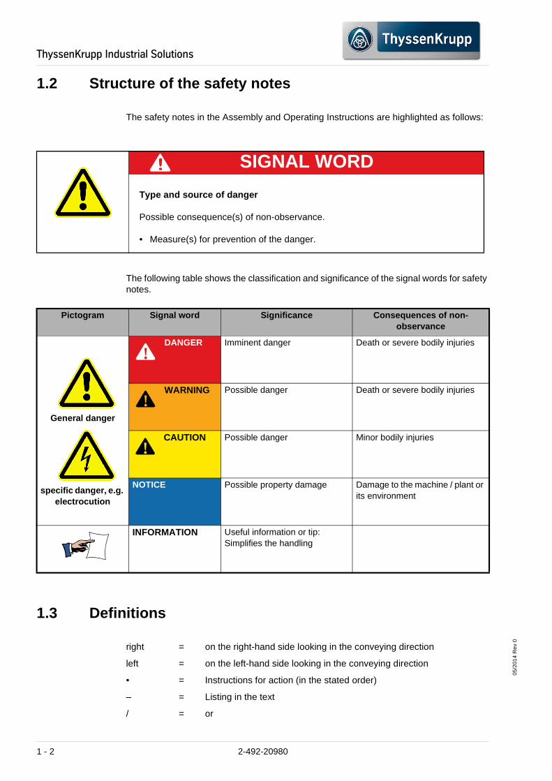
1.2 Structure of the safety notes
The safety notes in the Assembly and Operating Instructions are highlighted as follows:
The following table shows the classification and significance of the signal words for safety notes.
1.3 Definitions
right = on the right-hand side looking in the conveying direction
left = on the left-hand side looking in the conveying direction
• = Instructions for action (in the stated order)
– = Listing in the text
/ = or
SIGNAL WORD
Type and source of danger
Possible consequence(s) of non-observance.
• Measure(s) for prevention of the danger.
Pictogram Signal word Significance Consequences of non-observance
General danger
specific danger, e.g. electrocution
DANGER Imminent danger Death or severe bodily injuries
WARNING Possible danger Death or severe bodily injuries
CAUTION Possible danger Minor bodily injuries
NOTICE Possible property damage Damage to the machine / plant or its environment
INFORMATION Useful information or tip: Simplifies the handling
!
!
!
1 - 2 2-492-20980

05/2
014
Rev
0
ThyssenKrupp�Industrial�Solutions
1.4 General information
Dear Customer,
These Assembly and Operating Instructions are prepared by ThyssenKrupp Resource Technologies and have to be observed in every detail by those responsible for the transport, installation, commissioning, operation, maintenance as well as the disposal of all consumables and process materials. Only if the responsible individuals follow the instructions in these Assembly and Operating Instructions will errors in operating and servicing the machine/plant be avoided and trouble-free operation ensured.
The Assembly and Operating Instructions contain important information on how to operate the machine / plant safely, properly and efficiently. Observing this information helps to avoid danger, to reduce repair costs and downtimes and to increase both the reliability and the life of the machine/plant.
The Assembly and Operating Instructions include numerous instructions referring to possible hazards. The user is responsible for training the operating staff at the machine/plant or on site and ensuring that the safety regulations are observed.
The Assembly and Operating Instructions do not include instructions and guidelines for major repair work.
ThyssenKrupp Resource Technologies can provide skilled and qualified personnel to carry out inspections and repairs if required.
1.5 Liability and warranty
ThyssenKrupp Resource Technologies explicitly exclude all liability and warranty claims for damage or operational malfunctions originating from:
• Non-compliance with instructions in the Assembly and Operating Instructions
• Incorrect operation
• Any use of the machine other than the specified use
• Faulty maintenance
• Use of consumables (in particular lubricants) not explicitly permitted by the manufacturer
• Use of spare parts not approved by the manufacturer
• Conversions and modifications not approved by the manufacturer.
In addition, the conditions for liability and warranty as specified in the General Conditions of Supply of ThyssenKrupp Resource Technologies are applicable.
1.6 Copyright
We reserve all rights in connection with this documentation, including those relating to patent registration or provisional patent registration. This documentation may not be disclosed to third parties or reproduced or used in any other way without our previous consent in writing.
2-492-20980 1 - 3

05/2
014
Rev
0
ThyssenKrupp�Industrial�Solutions
1.7 Technical modifications
ThyssenKrupp Resource Technologies reserves the right to change designs in the course of technical developments. Recent modifications may not yet have been included in the drawings and texts of these Assembly and Operating Instructions.
1.8 Stocking of spare parts
Continuous operation and operational readiness of the machine/ plant can only be ensured if important spare and wear parts are held in stock.
Please order spare parts using the information contained in the spare parts list. The spare parts drawings listed in the spare parts list furnish additional information.
Our warranty only covers genuine spare parts supplied by us.
Please note that parts manufactured by us and non-company products are often subject to special production and delivery specifications.
NOTICE
The use of non-original spare parts
Damage to the machine/plant or its environment is possible
• Only use original spare parts that are approved by ThyssenKrupp Resource Technologies.
Damage caused by using products other than the original spare parts and accessories is excluded from the liability and warranty. We expressly point out that we cannot assume any liability for spare parts and accessories which have not been supplied by us. In some cases the installation of such products may alter and negatively affect the structural characteristics of the machine/plant and therefore impair safety.
1 - 4 2-492-20980

05/2
014
Rev
0
ThyssenKrupp�Industrial�Solutions
2 Technical data
2.1 Material
2.2 Power supply system
2.3 Process data
Operating mode: Loading using dumper with 170 t pay load
Feed material: Iron ore
Feed material size ROM: 1200 mm - 100%
450 mm - 80%
Moisture content: max. 2.0%
Specific gravity: 3,3 - 4.5 t/m³
Bulk density: 2,3 t/m³
Medium voltage: 4,16 kV; 3-phase; 60Hz
Low voltage: 460 kV; 3-phase; 60Hz
Light: 400 V/ 230 V; 3-phase/ 1-phase; 60Hz
Control voltage: 24 V DC; 120 V DC
Capacity rating: ≥ 3050 mt/h
Product size: 0 - 250 (X) mm
Product size: P80: ≤ 175 mm
2-492-20980 2 - 1

05/2
014
Rev
0
ThyssenKrupp�Industrial�Solutions
2.4 Gyratory crusher
Figure 1
2.4.1 Crusher type, dimensions, capacity
Crusher type: Gyratory crusher KB 63 - 75
Max. particle size feed: 1200 mm ROM 80% < 450 mm
Crushing: 0 - 250 (X) mm P80 ≤ 175 mm
Moisture content: max. 2%
Hardness: fmean = 150 MPa fmax = 250 MPa
Bulk density: 2,3 t/m³
2 - 2 2-492-20980

05/2
014
Rev
0
ThyssenKrupp�Industrial�Solutions
2.4.2 Oil circulating lubrication and hydraulic unit
2.4.3 Over-pressure ventilation of the dust sealing
2.4.4 Grease lubrication for spider bearing
Crusher work index: 10 kWh/t
Crushing gap OSS (design): approx. 175 mm XXX
Crusher mouth opening: approx. 1600 mm
Mantle diameter: 2030 mm
Stroke of the hydraulic cylinder: max. 280 mm
Circumferential back lash between bevel gear/bevel pinion:
suggested value +/- 15%
Oil tank: separate tank
Tank capacity lubricating oil: approx. 1500 litres
Tank capacity hydraulic oil: approx. 250 litres
Blower: Gasring-compressor, single-stage G 200 2BH1500-7AC19G with suction filter 2BX2102
Excess pressure: approx. 0.15 bar
Air flow rate: approx. 100 m³/h
Electric motor Voltage: Capacity P: Speed n:
460 V, 60 Hz 2.2 kW 1800 min-1
Weight: approx. 36 kg
Pneumatic barrel pump: 200 litres
2-492-20980 2 - 3

05/2
014
Rev
0
ThyssenKrupp�Industrial�Solutions
2.4.5 Drive unit
2.5 Discharge conveyor
Figure 2
The length described in the purchase order refers to the continuous length.
The add-on for closing the continuous length of the belt is provided by the supplier:
– delivered quantity in metre = continuous length (order quantity) + add-on
Motor: 750 kW, 60 Hz, 507 min-1
Safety coupling: BWL 125 special
Multiple-disc steel clutch: MTF 514
Belt width: 2000 mm
Centre distance: 47,7 m
Belt speed: max. 1.06 m/s
Angle of incline of belt: approx. 5 °
Steel cord belt: 2000 DIN 22102-EP2500/4 25:10 Y – open - GI
2 - 4 2-492-20980

05/2
014
Rev
0
ThyssenKrupp�Industrial�Solutions
2.5.1 Drive unit
2.5.2 Belt weigher
2.5.3 Metal detector
Type of gear: Bevel spur gearbox with back stop X4KR260HH/B
Transmission: 1:96
Oil quantity: approx. 270 litres, ISO VG 320 HC
Flange coupling: FC 775/275-S-M
Flexible coupling: ADR 125
Electric motor: 355 L4, 400 kW, 1800 min-1, B3
Weight drive complete, with motor:
approx. 9,500 kg
Mounting position - Drive: Conveying direction RIGHT
Model: 10-22-1 HD
Working temperature: -40 °C / +80 °C
Accuracy: +/- 0,03 %
Weight sensor: Thermentically sealed, temperature-compensated resistance strain gauges
Evaluation electronics: MicroTech™ 2001
Model: Oretronic III
2-492-20980 2 - 5
05/2
014
Rev
0
ThyssenKrupp�Industrial�Solutions
2.5.4 Safety devices
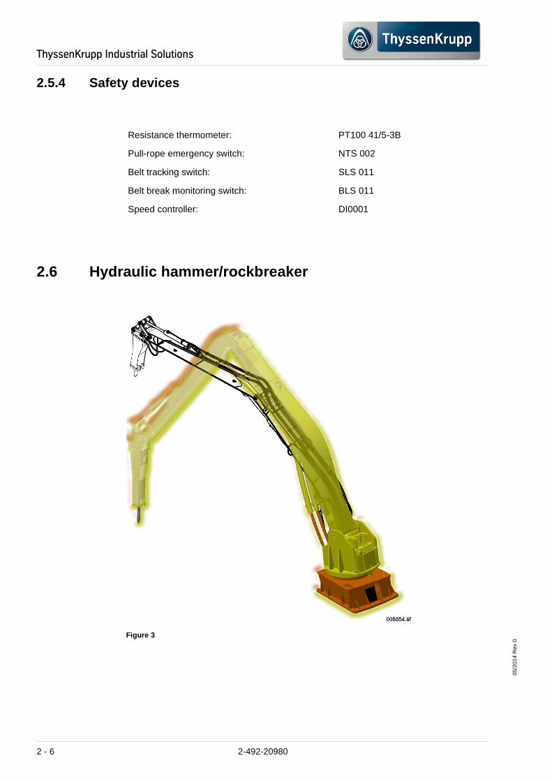
2.6 Hydraulic hammer/rockbreaker
Figure 3
Resistance thermometer: PT100 41/5-3B
Pull-rope emergency switch: NTS 002
Belt tracking switch: SLS 011
Belt break monitoring switch: BLS 011
Speed controller: DI0001
2 - 6 2-492-20980

05/2
014
Rev
0
ThyssenKrupp�Industrial�Solutions
2.7 Sprinkling system with desalination
Fixed boom system: RK 6151
Boom: 8,3 m
Arm: 8 m
Slewing angle: 180°
Hydraulic unit: HA 75 R
Capacity: 75/86 kW, 460 V, 50/60 Hz
Q: 200 l/min
Pmax: 320 bar
Hydraulic hammer: BTI BXR65
Usage weight: 2200 kg
Oil flow rate: 159 – 227 l/min
Working pressure:
150 – 190 bar
Shock frequency:
335 – 684 1/min
Diameter of work tool:
150 mm
Control and pump unit: CU-2/0 + 7
Electronic gyratory pump MVIE-414
Capacity: max. 9.0 m3/h
Supply line: 1x min. 5 x 2.5 or 4 mm2
Input voltage: 460 V / 60 Hz I 3 phase N and PE,
On-site fuse protection: 6.5 kW for system
Water input pressure: min. 1 bar to max. 5 bar
Water input: for min. 1 %''
Water quality: Drinking water, other qualities only as per agreement
2-492-20980 2 - 7

05/2
014
Rev
0
ThyssenKrupp�Industrial�Solutions
2.8 Maintenance car with scissor-type elevating plat form
2.8.1 Installation situation
Figure 4
Position A Park position (outside the crusher)
Position B Working position (under the crusher outlet)
2 - 8 2-492-20980

05/2
014
Rev
0
ThyssenKrupp�Industrial�Solutions
2.8.2 Dimensions and weights of the maintenance car (1) with elevating platform retracted (2)
2.8.3 Scissors-type elevating platform(2)
2.8.4 Drive unit (3)
Length x Width: 7500 mm x 4750 mm
Overall height including railing
with retracted elevating platform: approx. 2600 mm
with protruded elevating platform: approx. 4600 mm
Total weight: approx. XXX kg
Length x Width x Height: approx. 3700 x 3600 x 950 mm
Useful lift: 2,000 mm
Drive power: 7.5 kW
Load bearing capacity: 19.000 daN surface load 14,500 daN of the hydraulic cylinders + 1,000 daN accessories
Pressure generator: Hydraulic pump
Operating pressure of the hydraulic pump: 140 bar
Hydraulic cylinder: 2 x D160 / 100
Weight: XXX kg
Motor: Offset geared brake motor AFB 60 TD ZBA 90 AB 020
Capacity: 1,1 kW
Speed: 1400 min -1
Voltage: Motor 525 V, 50 Hz, brake 230 V 50 Hz
Protection class: IP 65 (brake IP 55)
2-492-20980 2 - 9

05/2
014
Rev
0
ThyssenKrupp�Industrial�Solutions
2.8.5 Detachable rail
After opening the discharge hopper make sure to use a detachable rail to prevent falling into the hopper.
Figure 5
2.8.6 Safety and monitoring equipment
Safety locking device for the access door
Type: AZM 200 SK - T - 1 P2 PW
Impulse generator for position recording
Type: IIM 201
2 - 10 2-492-20980

05/2
014
Rev
0
ThyssenKrupp�Industrial�Solutions
3 General safety notes
3.1 Principles
The machine/plant has been manufactured in accordance with the recognised safety regulations. However, this does not preclude danger to life and limb for the user or others, nor does it prevent harm to the machine/plant and/or other property.
– These safety instructions must be observed by all persons responsible for the transport, installation, commissioning, operation, maintenance as well as the dismantling and disposal of consumables and process materials. We recommend that the owner obtains a signed confirmation that the safety instructions have been read and understood by his personnel.
– The machine/plant may only be used in a technically perfect condition in accordance with its designated use and the instructions set out in the Operating Instructions, and only by safety-conscious persons who are fully aware of the risks involved in operating the machine/plant! Any malfunctions, especially those affecting the safety of the machine/plant, should therefore be rectified immediately.
– In addition to the Operating Instructions, observe and instruct the user in all other generally applicable legal and other mandatory regulations relevant to accident prevention and environmental protection.
These compulsory regulations may also deal with the handling of hazardous substances, issuing and/or wearing personal protective equipment (safety helmet, safety boots, safety goggles, hearing protection, respiratory protection).
• Observe all safety instructions and warnings attached to the machine/ plant!
• Ensure that safety instructions and warnings attached to the machine/plant are always complete and perfectly legible!
• In the event of safety-relevant modifications or changes in the behaviour of the machine/ plant during operation, stop the machine/ plant immediately and report the malfunction to the responsible department!
• Never make any modifications, additions or conversions to the machine/ plant which might affect safety without the supplier's approval! This also applies to the mounting and adjustment of safety devices and safety valves as well as to welding work on load-bearing elements.
• Replace hydraulic hoses within at appropriate intervals even if no safety-relevant defects have been detected!
• Comply with the prescribed intervals or those specified in the Operating Instructions for routine checks and inspections!
For the execution of maintenance work, tools and workshop equipment adapted to the task on hand are absolutely indispensable.
• The personnel must be familiar with the location and operation of fire extinguishers!
• Observe all fire-warning and fire-fighting procedures!
2-492-20980 3 - 1

05/2
014
Rev
0
ThyssenKrupp�Industrial�Solutions
3.2 Modifications and spare parts
– For safety reasons, conversions and modifications are prohibited unless previously approved by ThyssenKrupp Industrial Solutions.
– Use of accessories and spare parts not approved by ThyssenKrupp Industrial Solutions can lead to unforeseeable dangers.
3.3 Personnel
Personnel entrusted with work on the machine/plant must have read the operating instructions and in particular the chapter on safety before beginning work. Reading the Instructions after work has begun is too late. This applies especially to persons working only occasionally on the machine/plant, e.g. during setting up or maintenance.
For reasons of security, long hair must be tied back or otherwise secured, garments must be close-fitting and no jewellery - such as rings - may be worn. Injury may result from being caught up in the machinery or from rings catching on moving parts.
• Use protective equipment wherever required by the circumstances or by law!
Any work on and with the machine/plant may only be carried out by reliable personnel. Statutory minimum age limits must be observed!
Employ only trained or instructed staff and set out clearly the individual responsibilities of the personnel for operation, set-up, maintenance and repair!
• Define the machine operator's responsibilities - also with regard to observing traffic regulations - giving the operator the authority to refuse to carry out instructions by third parties which compromise safety!
Work on the electrical system and equipment of the machine/plant may only be carried out by a skilled electrician or by instructed persons under the supervision and guidance of a skilled electrician and in accordance with electrical engineering rules and regulations.
Work on the hydraulic system must be carried out only by personnel with special knowledge and experience of hydraulic equipment!
3 - 2 2-492-20980

05/2
014
Rev
0
ThyssenKrupp�Industrial�Solutions
3.4 Noise hazard
Information on the emissions level which is specifi c to the work station
No permanent work station has been assigned to the machine/ plant.
Depending on the material to be processed, noise emissions will occur: these may only be measured during operation. The user has to ensure the measurement of the sound power level of all operation positions (e.g. for maintenance and checking, control station) immediately after commissioning.
3.5 Information regarding residual risks during dail y operation
The safety requirements specified in the EC Machines Directive have been taken into account in the machine/plant.
Residual risks can nevertheless still occur during operation.
Residual risks, which remain even after careful shutting off and with platforms corresponding to the applicable safety requirements, are pointed out below.
Mechanical hazard/material
– Overcharging and discharge of crushing material on account of upstream conveying equipment and/or congestion of material in the feed hopper.
– Dusty operating conditions on account of the type of feeding material, material feeding, the crushing procedure, the material discharge.
CAUTION
Risk of injury when working without ear protection
Bodily injury possible
• Directive 2003/10/EC of the European Parliament and of the Council dated 06/02/2003 (17th individual directive in terms of Article 16 Paragraph 1 of the Directive 89/391/EEC). The plant operator must make suitable, correctly fitting ear protection available to employees who must use this when noise emissions reach the upper limit values 85 dB(A) .
• ThyssenKrupp Resource Technologies recommends that plant operators keep suitable ear protection available for their employees for noise levels from 80 dB(A) .
2-492-20980 3 - 3

05/2
014
Rev
0
ThyssenKrupp�Industrial�Solutions
3.6 Fire protection
• The legal requirements regarding fire protection and fire prevention have to be complied with and supplemented with in-company regulations. The fire-fighting experts of the insurance companies should also be consulted in this process.
• Appoint supervisors who are in charge of all the matters related to fire prevention and fire fighting and provide them with the knowledge required for this task. The management staff and the engineers have to support them in their task by providing consultation to them.
The supervisor must check the fire extinguishing equipment at regular intervals, in order to ensure that the equipment is always ready for use. Rooms which are easily flammable require particular attention in this context!
The persons commissioned with supervision and fire fighting must have attended a first aid course. First aid stations must be provided.
• The fire protection regulations must be posted at different locations in the plant.
• The personnel must be informed about the fire protection measures. Any case of fire must be reported immediately.
• The units and the assembly groups which heat up more strongly during operation on account of the electrical and/or mechanical stress to which they are exposed must be monitored by the responsible personnel. This applies e.g. to compressors, gear units, bearings, motors, oil/hydraulic units.
The fire extinguishers must be easily accessible and may not be obstructed by objects.
• The personnel must be familiarised with the use of the fire extinguishers to such a degree that they are capable of fighting fire outbreaks with the appropriate fire extinguishers.
Fire-fighting rules
– Use fire-fighting water for burning wood, waste, fabric, jute, paper, belts, etc.
– In case of burning liquids (mineral oil, petrol, oil, petroleum, paints, tar, etc.), always use CO2 extinguishers and (powder type) fire extinguishers.
– In case of burning cables, motors, electric plants, etc. only use (powder type) fire extinguishers or CO2 fire extinguishers.
3.7 Disposal of consumables and process materials
• The safe and environment-friendly disposal of all consumables and process materials should be ensured. You should also make sure that all respective national regulations for the protection of the environment are complied with.
3 - 4 2-492-20980

05/2
014
Rev
0
ThyssenKrupp�Industrial�Solutions
2-492-20980 3 - 5

ThyssenKrupp�Industrial�Solutions
05/2
014
Rev
0
Blank page
3 - 6 2-492-20980

05/2
014
Rev
0
ThyssenKrupp�Industrial�Solutions
4 Design and operating principle
4.1 Scope of application and designated use
DANGER
Risk of injury through operating the machine/plant with unauthorised modifications, conversions or spare parts
Imminent danger of death or severe bodily injuries
• ThyssenKrupp Resource Technologies explicitly excludes all liability and warranty claims if modifications/conversions are made without the express permission in writing of the manufacturer.
• Only operate the machine/plant in its original condition. Any deviations from the original condition must be reported by the operator to the responsible department.
NOTICE
System damage through use of the machine/plant cont rary to its designated use
Damage to the machine/plant or its environment is possible
The intended use of the machine/plant is regulated by contract. Any other use contrary to its designated use is prohibited. ThyssenKrupp Resource Technologies cannot be held liable for damage resulting from such misuse. The risk of such misuse lies entirely with the user.
• The gyratory crusher must be constantly fed with material to ensure that the crushing chamber is always at least 80 % full.
• The machine/plant must be used exclusively for the intended purpose agreed upon with the manufacturer.
• Observe the Assembly and Operating Instructions.
2-492-20980 4 - 1

05/2
014
Rev
0
ThyssenKrupp�Industrial�Solutions
The constant feeding ensures that the main shaft bearing is always uniformly loaded ("quiet load running").
At the same time a stable film of lubrication keeps wear to a minimum on all of the affected bearing components.
This method also has a positive effect on the wear pattern of the crushing tools.
Frequent idle-running phases lead to uncontrolled movements of the main shaft in the spider head bearing and in the lower bearing bushing. At the same time, continuous re-filling of the crushing chamber causes fluctuating loads and consequently uneven running under load.
This impact-type method of operation destabilises the lubricating film between the bearing components which can cause undesirable abrasion on the bearing positions.
This negative operating mode leads to an uneven wear patter with respect to the crushing tools / wear parts.
Prior to the use of the machine/ plant beyond this scope of application, consult the after-sales service. Otherwise the warranty will lapse.
4.2 Climatic conditions/ environmental conditions
The manufacturer ThyssenKrupp Resource Technologies must be consulted when the machine is operated at temperatures not within the above range. The expanded use must be approved by ThyssenKrupp Resource Technologies.
4.3 Functional description of the system
Dump trucks with a capacity of 170 mt transport the material from the mining area to the semi-mobile crushing plant.
The vehicles load the material directly into the feed hopper via two truck ramps. The bunker is equipped with water pipes and nozzles for the suppression of dust.
Place of installation: Peru
Altitude: 700 - 900 m above sea level
Min. temperature: + 7 °C
Max. temperature: + 28.2 °C
Average temperature: + 16.7 °C
Relative humidity: TBA
Wind velocity: 20 m/ s
Seismic factor: UBC Zone 3
4 - 2 2-492-20980

05/2
014
Rev
0
ThyssenKrupp�Industrial�Solutions
From the discharge hopper the crushed material is loaded onto the speed-controlled discharge conveyor below the crusher and transferred from there to the conveyor belt system.
Metallic foreign bodies are detected by a metal detector and marked with a flag. The metallic foreign bodies are then sorted out by hand.
The crushing plant is controlled from the control room near the crusher. The electrical drive unit are locked so that maximum operational safety is ensured. The electrical equipment is installed in air-conditioned containers, separated from the semi-mobile crushing plant.
The system is equipped with a rockbreaker, which allows the crushing of oversized stones.
The plant has a bridge crane with 80/20 t lifting capacity and an external maintenance stand for servicing the main shaft.
A maintenance car with a hydraulic scissor lifting platform can be moved in and out of the discharge hopper. It provides support disassembling the hydraulic cylinder below the crusher.
4.4 Components of the semi-mobile crushing plant
4.4.1 Truck ramps
– Two ramps for dump trucks with 170 mt loading capacity.
– Made of corrugated, welded steel plates, including calotte storage and coupling link for anchoring. (concrete by customer)
Figure 6
2-492-20980 4 - 3

05/2
014
Rev
0
ThyssenKrupp�Industrial�Solutions
4.4.2 Steel structure
Figure 7
– of the steel construction The feed hopper consists of thickly ribbed, welded steel plates (25-mm plates plus 50-mm wear plates) and the necessary fasteners for assembly of the bunker on to the carrying frame.
–
– The discharge hopper consists of ribbed, welded steel plates with liner plates (15-mm plates plus 20-mm liner plates) and the necessary fasteners for assembly of the bunker on to the main frame.
– ... Pontoons with 4 stands
– Platforms, walkways and stairs for access during maintenance and operation with grid iron and corrugated sheet metal, as well as handrails for all stairs and walkways
4 - 4 2-492-20980

05/2
014
Rev
0
ThyssenKrupp�Industrial�Solutions
The main frame consists of a welded box structure, in order to ensure maximum stability when under enormous static and dynamic stresses during the crushing operation.
This main frame carries all of the equipment and all of the components.
The structures, platforms, walkways and stairs are made of sectional steel.
The entire configuration stands on two heavy pontoons based on a prepared bed of gravel.
The primary gyratory crusher KB63-89 consists of: The heavy duty spider is made of cast steel and consists of two heavy spider arms which are necessary for the central hub.
The spider arms are protected from wear by so-called arm liners.
The main shaft is supported and centred in the spider by the spider bearing. The spider bearing is protected by the spider cap.
The spider cap is made of cast steel and contains the central hub and prevents contaminants from entering into the spider bearing. The spider cap reduces maintenance downtime and provides a service longer life.
The helmet is designed as a "slide-on" unit which requires no mounting screws.
Figure 8
The multi-part crusher housing also consists of the upper shell (1), the lower shell (2) and the lower part (3).
The heat-treated cast steel constructions are reinforced with circumferential ribbing between the upper and lower flange of each section and also with vertical bracing for added strength during initial crushing.
Shells (1, 2) and lower section (3) are positioned using conical seats and bolted to the external flanges.
The lower section is equipped with liner plates. It is connected to the internal hub via three arms. One of the arms is suited for the installation of the pinion shaft assembly (pinion assembly tunnel). The compressed air piping for the dust sealing and the lubrication oil piping are installed in one arm and lead to the outer eccentric bushing of the external lubrication circuit. The arms are protected against damage caused from impacting material by liner plates.
The hub in the centre holds the outer eccentric bushing. The eccentric bushing is located in the outer eccentric bushing. The dust sealing is mounted on top of the hub.
The base plate (including axial step bearing ring) is bolted to the lower section, which supports the eccentric bushing in the axial direction. The hydraulic cylinder supports the axial step bearing and is located under the base plate. The hydraulic cylinder is also bolted to the lower section.
The lower section has two inspection opening covers. An inspection opening with a cover is located on the lower section of the hub for checking the bevel gear and the pinion.
The bottom flange of the lower section is used to mount the lower section on the substructure / foundation.
The main shaft is made of forged steel. A protective nut with a burn protection ring is screwed onto the main shaft.
The eye bolt is used to assemble/disassemble the main shaft.
The sealing ring of the dust sealing is bolted to the bottom side of the main shaft.
The upper section of the main shaft is protected by the main shaft sleeve.
The step bearing upper part is mounted on the lower face of the main shaft.
2-492-20980 4 - 5

05/2
014
Rev
0
ThyssenKrupp�Industrial�Solutions
The mantle is attached to the shaft cone. The mantle are held together on the shaft cone with an external ring nut and an intermediate ring.
The outer ring nut is protected against wear by a cap and hard facing.
The mantle is backfilled with a special plastic sealing compound.
– Concaves
The concave segments are made of manganese steel and arranged in four rows.
The bottom row is curved in order to increase resistance and the range of the mantle adjustment.
If necessary the design of the concave surfaces can be modified in order to improve the crushing performance.
The concaves are backfilled with a special plastic sealing compound.The dust sealing protects the section of the oil circulating lubrication inside the gyratory crusher against the ingress of dust from the crushing chamber.
The internal area is sealed with a plastic ring which is mounted with play between the top and bottom sealing rings. A small amount of axial play exists between the plastic ring and the sealing housing. The plastic ring follows the wobbling movement of the main shaft.
A separately arranged blower also generates a slight over-pressure inside the gyratory crusher.
As a result, there is a continuous air flow from the interior of the crusher to the crushing chamber. This prevents the ingress of dust and other pollutants.
Figure 9
The eccentric bushing is driven by the pinion assembly. It guides the main shaft in the inner eccentric bushing and produces its wobbling (rotary/oscillating) motion.
The eccentric bushing is lubricated by the oil circulating lubrication internally (between the inner eccentric bushing and the main shaft), externally (between the eccentric bushing and the outer eccentric bushing) and on the underside (between the eccentric bushing and the axial step bearing ring).
The circulating lubrication also supplies the teeth of the bevel gear.
The top device for compensating unbalance fixes the inner eccentric bushing in a vertical (axial) direction.
The connection between the electric motor and the pinion assembly is the drive.
The multiple-disc steel clutch between pinion shaft and the electric motor is used to compensate slight misalignment between the motor shaft journal and the pinion shaft assembly.
The distance tube allows the pinion assembly to be removed without shifting the drive motor.
The safety coupling is provided with a torque limiter with hydraulic torque setting. The necessary releasing torque is set by varying the hydraulic pressure.
The pinion assembly is arranged in the pinion assembly tunnel of the bottom shell of the crusher.
The pinion shaft assembly sprocket for driving of the bevel gear of the eccentric bushing is supported with roller bearings in the pinion assembly housing.
The bearings are lubricated by the oil filling in the pinion assembly housing (stand oil lubrication).
By changing the thickness of the discs, the contact pattern of the bevel gear teeth and the backlash can be adjusted.
4 - 6 2-492-20980

05/2
014
Rev
0
ThyssenKrupp�Industrial�Solutions
4.5 Hydraulic hammer/rockbreaker
Figure 10
Belt width: 2000 mm
Centre distance: 47,7 m
Belt speed: 1,06 m/s at 60 Hz
Angle of incline of belt: approx. 5 °
Steel cord belt: Belt 2000 DIN 22102-EP2500/4 25:10 Y – open - GI
Type of gear: Bevel spur gearbox with back stop X4KR260HH/B
Transmission: 1:96
Flange coupling: FC 775/275-S-M
Flexible coupling: ADR 125
Electric motor: 355 L4, 400 kW, 1800 min-1, B3
Mounting position - Drive: Conveying direction RIGHT
2-492-20980 4 - 7

05/2
014
Rev
0
ThyssenKrupp�Industrial�Solutions
4.6 Sprinkling system for dust reduction
Fixed boom system: RK 6151
Boom: 8,3 m
Arm: 8 m
Slewing angle: 180°
Hydraulic unit: HA 75 R
Capacity: 75 kW, 525 V, 50 Hz
Q: 200 l/min
Pmax: 320 bar
Hydraulic hammer: BTI BXR65
Usage weight: 2200 kg
Oil flow rate: 159 – 227 l/min
Working pressure:
150 – 190 bar
Shock frequency:
335 – 684 1/min
Diameter of work tool:
150 mm
Control and pump unit: CU-2/0 + 7
Electronic gyratory pump MVIE-414
Capacity: max. 9.0 m³/h
Supply line: 1x min. 5 x 2.5 or 4 mm2
Input voltage: 400 V I 60 Hz I 3 phases N and PE,
On-site fuse protection: 6,5 kW for system
Water input pressure: min. 1 bar to max. 5 bar
Water input: for min. 1 %''
Water quality: Drinking water, other qualities only as per agreement
4 - 8 2-492-20980

05/2
014
Rev
0
ThyssenKrupp�Industrial�Solutions
4.7 Maintenance car with scissor-type elevating plat form
4.7.1 Installation situation
Figure 11
Position A Park position (outside the crusher)
Position B Working position (under the crusher outlet)
2-492-20980 4 - 9

05/2
014
Rev
0
ThyssenKrupp�Industrial�Solutions
4.7.2 Dimensions and weights of the maintenance car (1) with elevating platform retracted (2)
Figure 12
Length x Width: approx. 7470 mm x 4640 mm
Overall height including railing
with retracted elevating platform: approx. 2430 mm
with protruded elevating platform: approx. 4400 mm
Total weight: approx. 13,500 kg
4 - 10 2-492-20980

05/2
014
Rev
0
ThyssenKrupp�Industrial�Solutions
4.7.3 Scissors-type elevating platform(2)
4.7.4 Drive unit (3)
4.7.5 Safety and monitoring equipment
Safety locking device for the access door
Type: AZM 161 SK - 12/12RK-024
Limit switch stroke end, lowering
Type: Schmersal ZV7H236-11Z-2138
Protective foot strip limit switch
Type: Telemecanique XCKD2121P16
Length x Width x Height: approx. 3700 x 3600 x 950 mm
Useful lift: approx. 1800 mm
Drive power: 7,5 kW
Load bearing capacity: 19,000 daN
Pressure generator: Hydraulic pump
Operating pressure of the hydraulic pump: 140 bar
Hydraulic cylinder: 2 x D160 / 100
Weight: 5,800 kg
Motor: Electric motor
Capacity: 7,5 kW
Voltage: 460 V, 60 Hz
Protection class: IP 55
2-492-20980 4 - 11

ThyssenKrupp�Industrial�Solutions
05/2
014
Rev
0
Blank page
4 - 12 2-492-20980

05/2
014
Rev
0
ThyssenKrupp�Industrial�Solutions
5 Transport, storage and assembly
5.1 Transport instructions
The machine/plant is transported in component parts or as assembly groups. Make sure that suitable lifting tackle is used to unload the parts from the transport vehicles and move them to the storage location.
The machine/plant must be transported with adequate care in order to prevent damage and not endanger staff. In addition to the following information, the general and local safety and accident prevention regulations must be observed. Overhead gantries and mobile cranes or lifting tackle with a sufficient load bearing capacity must be available to carry out the unloading, transport/loading safely and correctly.
The transport and storage symbols on the machine packaging must be heeded.
When transporting the machine by crane, only use suitable loading devices.
When packing the machine, loading devices may only be attached at the marked points.
Keep away from heat Keep dry Caution! Glass! This way up
Sling here Centre of gravity Do not use hand hooks
No hand truck here
Stacking limitation Clamp here Permissible temperature range
Do not use fork lift truck here
Electrostatic sensitive device
Do not destroy barrier Tear off here Do not roll
2-492-20980 5 - 1

05/2
014
Rev
0
ThyssenKrupp�Industrial�Solutions
Check all components for transport damage after delivery to the site.
DANGER
Risk of injury due to the improper transport of the machine/plant
Imminent danger of death or severe bodily injuries
• Only transport the machine/plant on the designated slinging devices (lugs) and slinging points.
• The fastening of loads and the instruction of crane operators should only be entrusted to experienced persons! The marshaller must be within eyesight of the operator or have verbal communication with him.
• Make sure to use proper transportation equipment.
• Do not walk under suspended loads.
• Secure moveable components.
NOTICE
System damage from improper transport of the machin e/plant
Damage to the machine/plant or its environment is possible
• Do not attach any additional slinging points to the machine through welding, torching or drilling (notching effects and the corresponding risk of crack formation).
• Do not push together the side walls or the attachment parts of the machine by pulling lifting gear at an angle!
• If transport securing devices have been furnished do not remove them until installation has been completed.
5 - 2 2-492-20980

05/2
014
Rev
0
ThyssenKrupp�Industrial�Solutions
5.2 Hoisting devices and slinging equipment
5.2.1 Lifting gear
Usually, cranes and lifting gear is used for transporting heavy assembly groups and components. Slinging equipment such as ropes and hooks are critical elements between the load and lifting equipment.
Safe lifting requires adequately dimensioned and suitably designed lifting gear and slinging equipment to be used, as well as correct attachment and fixing to the load.
The weight of assembly groups and components is specified in the spare parts catalogue / in the Operating Instructions, so that equipment such as e. g. hoisting devices, winches, cranes, lifting chains can be selected accordingly.
Check hydraulic winches for proper function before use. Only use winches with adjustment ring. This allows loads to be supported mechanically and prevents their lowering.
5.2.2 Lifting
• Before lifting, determine the weight of the load.
• Determine the size and shape of the load; two criteria which determine the following:
– the type of load securing, e. g. with slings, baskets or slings with special fixtures,
– the slinging equipment / load securing fixtures, e. g. lifting rope, lifting chain, screw eyes, yokes (see following chapters),
– the load angle of the slinging equipment.
• Determine the thickness of the slinging equipment to be used. Do not exceed the permissible load bearing capacity of the slinging equipment.
WARNING
Risk of injury through components that are improper ly secured during installation
Death or severe bodily injury is possible.
• Make sure that moveable components are properly secured during installation
INFORMATION
Before lifting heavy loads, attach a load cell to check the load.
2-492-20980 5 - 3
05/2
014
Rev
0
ThyssenKrupp�Industrial�Solutions
• If any of the following points are unclear, consult the assembly supervisor responsible:
– correct attachment method,
– selected thickness of slinging equipment,
– type of slinging equipment.
• Check the slinging equipment for damage / faults. Make sure that any faulty slinging equipment is discarded immediately.
• Do not overload slinging equipment and protect it against sharp corners and edges of the load e. g. through edge/corner protection made of sacking or metal, boards etc.
• Protect high-gloss/finished surfaces of the load against damage caused by the slinging equipment. Protective material that is intended to prevent the load/lifting means slipping must be attached in such a way that it cannot slip if the slinging equipment becomes loose.
• When attaching slinging equipment at great heights:
– Use the climbing aids provided. If no climbing aids have been provided or these are not available, use an approved ladder.
– Secure the ladder to prevent it slipping or falling over.
– Use both hands for climbing. Have the slinging equipment to be attached brought up by lifting tackle (e. g. crane).
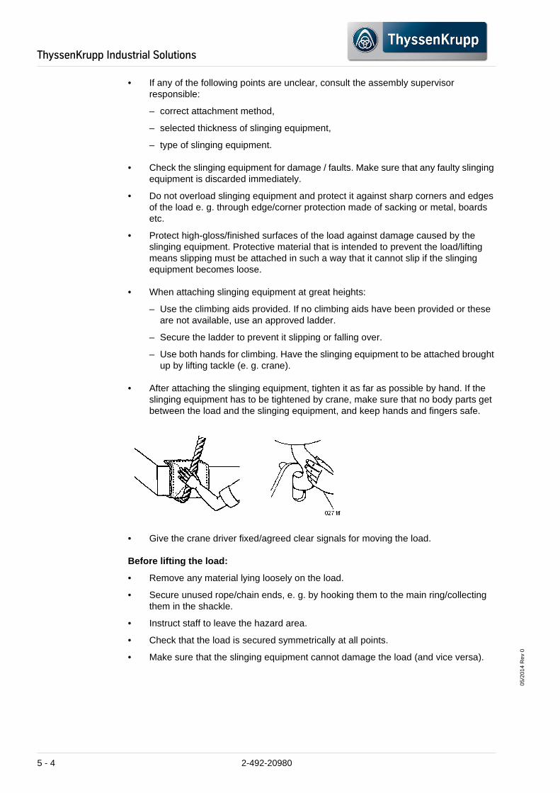
• After attaching the slinging equipment, tighten it as far as possible by hand. If the slinging equipment has to be tightened by crane, make sure that no body parts get between the load and the slinging equipment, and keep hands and fingers safe.
• Give the crane driver fixed/agreed clear signals for moving the load.
Before lifting the load:
• Remove any material lying loosely on the load.
• Secure unused rope/chain ends, e. g. by hooking them to the main ring/collecting them in the shackle.
• Instruct staff to leave the hazard area.
• Check that the load is secured symmetrically at all points.
• Make sure that the slinging equipment cannot damage the load (and vice versa).
5 - 4 2-492-20980

05/2
014
Rev
0
ThyssenKrupp�Industrial�Solutions
After the weight of the load has been picked up com pletely by the lifting tackle and the load has been lifted a little:
• Check the load brake.
• Check again whether the load is secured at all points.
• Transport the load over free areas as far as possible.
• Warning signals must be given if there is anyone in the hazard zone.
Setting the load down:
• Set the load down slowly on a respectively sturdy base. Align the base again before the load is set down.
• Remove slinging equipment from the load and check both for damage.
5.2.3 Lifting ropes
The number of sling points is equal to the number of rope strands connecting the crane hook with the load. A load angle i. e. an angle between the horizontal surface of the load and the lifting ropes is formed by several strands. The smaller the load angle, the smaller the permissible load bearing capacity of the lifting ropes and thus the effectiveness.
Effectiveness of the load angle
Load angle Load bearing capacity
%
max. permissible load per strand in relation to 1000 kg
30° 50,0 (500 kg)
45° 70,7 (707 kg)
60° 86,6 (866 kg)
90° 100,0 (1000 kg)
2-492-20980 5 - 5

05/2
014
Rev
0
ThyssenKrupp�Industrial�Solutions
The load bearing capacity/wire rope strength is reduced by:
– Splitting rope loops in the lifting ropes and splitting lifting ropes into continual strands
– Bending round corners
– Using lifting ropes for clamping
– Acceleration and slowing during lifting and lowering operation
– General wear
– High and low temperatures
– Vibration
– Corrosion
Use:
Although the weight of lifting ropes is lower than that of lifting chains of the same load bearing capacity, they have a few disadvantages. They can become damaged more easily and are more difficult to handle since their bending radius is smaller.
Lifting ropes are suitable for vertical lifting operation or for lifting operation where ropes must be routed in a large radius around corners.
The thickness of a wire rope is given in relation to its outer diameter.
• Protect lifting ropes from the influences of the weather, solvents, high temperatures and chemicals.
• Avoid knots forming in wire ropes. In the event of a knot, do not use the rope again.
• Protect ropes against sharp-edged corners by enlarging the corner radius. This can be by means of metallic corner protection devices or blocks. Sacking and wooden boards can also be used.
• The correct procedure for securing lifting ropes to the hook is as follows:
– Secure each individual strand on the hook to prevent hitching at the hook.
– Never use one single slinging rope strand since this could lead to the load rotating. The wire rope could be untwisted and thus the splice pulled out.
• Never wind the wire rope completely around the crane hook (i. e. by 360 degrees). The low bending radius would damage the rope.
• Check the lifting ropes for:
– broken or cut strands,
– rust and corrosion,
– knots and kinked spots,
– damaged eyes
5 - 6 2-492-20980

05/2
014
Rev
0
ThyssenKrupp�Industrial�Solutions
• Do not bend the eyes of lifting ropes over corners.
• When securing loads by winding the lifting ropes around the load, use shackles (1).
5.2.4 Wire rope clamps
Attach wire rope clips in such a way that the lower part of the clip (6) is pushed against the long end (5) of the rope, and the yoke of the clip (2) against the dead end (4) of the rope. Always attach a rope thimble (1). The correct number of clips and distance (3) between them is given in the following table.
Tighten clamping nuts using the given torques.
Once the rope has been put into operation and is tensioned, tighten the clamping nuts again. Check the clamping nuts regularly and tighten if necessary. This compensates rope expansion and the related reduction of rope radius.
Rope diameter Diameter of the clamping yoke
Distance between clips Required minimum number of clips
Inches mm Inches mm Inches mm
3/16 4,76 11/32 8,73 3 76 2
1/4 6,35 7/16 11,11 3-1/4 83 2
5/16 7,94 1/2 12,70 3-1/4 83 2
3/8 9,53 9/16 14,29 4 102 2
7/16 11,11 5/8 15,88 4-1/2 114 2
2-492-20980 5 - 7

05/2
014
Rev
0
ThyssenKrupp�Industrial�Solutions
5.2.5 Lifting chains
Use:
Lifting chains are made of alloyed steel and are sturdier and more flexible than lifting ropes, but they are not as resistant to impact loads as ropes are. The thickness of a chain is determined in relation to the diameter (1) of a chain link.
• Avoid knots forming in lifting chains. They weaken the chain strand and can lead to deformation or other damage to the chain links.
1/2 12,70 11/16 17,46 5 127 3
5/8 15,88 3/4 19,05 5-3/4 146 3
3/4 19,05 7/8 22,23 6-3/4 172 4
7/8 22,23 1 25,40 8 203 4
1 25,40 1-1/8 28,58 8-3/4 222 4
1-1/8 28,58 1-1/4 31,75 9-3/4 248 5
1-1/4 31,75 1-5/16 36,51 10-3/4 273 5
1-3/8 34,93 1-1/2 38,10 11-1/2 292 6
1-1/2 38,10 1-23/32 43,66 12-1/2 318 6
1-5/8 41,28 1-3/4 44,45 13-1/4 337 6
1-3/4 44,45 1-15/16 49,21 14-1/2 368 7
2 50,80 2-1/8 53,98 16-1/2 419 8
2-1/4 57,15 2-5/8 66,68 16-1/2 419 8
2-1/2 63,50 2-7/8 69,85 17-3/4 451 8
Rope diameter Diameter of the clamping yoke
Distance between clips Required minimum number of clips
Inches mm Inches mm Inches mm
5 - 8 2-492-20980

05/2
014
Rev
0
ThyssenKrupp�Industrial�Solutions
• Shorten lifting chains by hooking them back into the chain or into the main line with the aid of a gripper hook. Never shorten a chain by twisting, knotting or through bolts.
• Protect lifting chains against sharp corners and edges that could deform the chain links. Use suitable flexible boards or metallic corner protection devices.
• If the chain for lifting operation is to be wound around the load to be lifted, always turn the hook opening away from the direction in which the slings are to be pulled. This prevents the hook slipping out when the slings are tightened.
• Check lifting chains for:
– notches, cracks, exact dimensions and wear
– deformed chain links, welding burr, bent or open hooks, elongation
– rust and corrosion
• If all the strands of a lifting chain can be hooked back into the main line, the permissible load bearing capacity of the whole sling can be increased by 50 %.
2-492-20980 5 - 9

05/2
014
Rev
0
ThyssenKrupp�Industrial�Solutions
5.2.6 Hook
The load bearing capacity is usually stamped into the hook.
• If possible, use a hook with spring-loaded snap-in locking devices. If such hooks are not available, the hook has to be secured temporarily as shown in the diagram.
5.2.7 Screw-type lifting eyes
The size of screw-type lifting eyes is determined in relation to the diameter of the shank of the threaded section. A distinction is made between simple screw-type eyes and screw-type eyes with shoulder.
• For vertical lifting operation, use simple screw-type eyes (without shoulder).
• Screw-type eyes with shoulder are used when loads are to be lifted at certain angles (e. g. lifting operation with several lifting ropes).
The permissible load bearing capacity that has already been reduced by the load angle, is reduced even further by the use of screw-type eyes.
An eye bolt with a shoulder, which is used for example at an angle of 45°, can only be used for up approximately 10 % of the permissible load for vertical lifting.
5 - 10 2-492-20980

05/2
014
Rev
0
ThyssenKrupp�Industrial�Solutions
Permissible loads for eye bolts with shoulders:
Eyes must be screwed in completely to prevent the shank becoming bent.
Shank diameter Vertical lifting operation
Tension at 60° to the shoulder level
Tension at 45° to the shoulder level
Tension at 90° or loose side pull
per screw-type eye per screw-type eye per screw-type eye per screw-type eye
Inches mm Pounds kg Pounds kg Pounds kg Pounds kg
1/4 6,4 300 136 50 23 30 14 40 18
1/2 12,7 1300 590 200 91 140 64 150 68
3/4 19,3 3000 1361 400 181 250 113 300 136
1 25,4 6000 2722 800 363 500 227 600 272
1-1/4 31,8 9000 4082 1300 590 800 363 900 408
1-1/2 38,1 13000 5897 1800 816 1200 544 1300 590
2 50,8 23000 10433 3300 1497 2100 953 2300 1043
2-1/2 63,5 37000 16783 6000 2722 3500 1724 4300 1950
2-492-20980 5 - 11

05/2
014
Rev
0
ThyssenKrupp�Industrial�Solutions
• Use screw-type eyes of a suitable size.
• Check the condition of the thread to make sure the screw-type eye fits tightly and that there is flush and complete contact between the shoulder and the load. Never use screw-type eyes with cracked or flawed threads.
• Only use screw-type eyes the load bearing capacity of which is suitable for the load, i. e. shanks with threads that fit exactly in standard boring holes.
• Check shanks of the screw-type eyes for deformation or crack formation.
• Use hardened washers to make sure the edges of the screw-type eye are a tight fit. The washers must not be thicker than two threads.
5.2.8 Shackles
Shackles are closed safety devices that cannot be hooked out. Their size is determined in relation to the diameter of the main part (1) and not in relation to the diameter of the bolt. A distinction is made between anchor load shackles (on the left of the diagram) and chain load shackles (on the right).
• Do not expose the main part of the shackle to side tensile loads.
• Ensure the shackle bolt is a perfect fit.
• The permissible load for anchor load and chain load shackles as well as for screw-type or socket pin is always the same.
DANGER
Danger caused through the use of improper slinging equipment
Imminent danger of death or severe bodily injuries
• Never replace shackle bolts by conventional bolts. Danger of breaking!
5 - 12 2-492-20980
05/2
014
Rev
0
ThyssenKrupp�Industrial�Solutions
• If shackles are used at load angles other than 90°, the permissible load bearing capacity is reduced; see table:
Diameter Single shackle vertical
Two shackles 60° Two shackles 45° Two shackles 30°
Inches mm Americ. tonnes
tonnes Americ. tonnes
tonnes Americ. tonnes
tonnes Americ. tonnes
tonnes
1/4 6,4 1/3 0,3 3/4 0,7 1/2 0,5 1/3 0,3
5/16 7,9 1/2 0,5 1 0,9 ¾ 0,7 1/2 0,5
3/8 9,5 3/4 0,7 1-1/4 1,1 1 0,9 3/4 0,7
7/16 11,1 1 0,9 1-3/4 1,6 1-1/2 1,4 1 0,9
1/2 12,7 1-1/2 1,4 2-1/2 2,3 2 1,8 1-1/2 1,4
5/8 15,9 2 1,8 3-3/4 3,4 3 2,7 2 1,8
3/4 19,3 3 2,7 5-1/2 5 4-1/2 4,1 3 2,7
7/8 22,2 4 3 6 7 6 3 5-1/2 5
1 25,4 5-1/2 5 10 9 8 7,2 6 5,4
1-1/8 28,6 6-1/2 5,9 11-1/2 10,5 9-1/2 8,5 6-1/2 5,9
1-1/4 31,8 8 7,2 14 12,7 12 10,8 8 7,2
1-3/8 24,9 10 9 17 15,4 14 12,7 10 9
1-1/2 38,1 12 10,8 20 18,1 17 15,4 12 10,8
1-3/4 44,5 16 14,5 28 25,4 23 20,9 16 14,5
2 50,8 21 19 36 32,6 30 27,1 21 19
2-1/4 57,2 27 24,5 46 41.7 38 34,5 27 24,5
2-1/2 63,5 34 31 58 52,6 48 44 34 31
2-3/4 70,1 40 36,2 69 62,9 57 51,9 40 36,2
3 76,2 80 45,3 87 78,8 71 64.4 50 45,3
4 101,6 100 90,7 173 156,9 142 128,7 100 90,7
2-492-20980 5 - 13

05/2
014
Rev
0
ThyssenKrupp�Industrial�Solutions
5.2.9 Slinging equipment and load protection
• Protect lifting ropes against sharp edges/corners. Use materials to enlarge the radius, e. g. metallic corner protection devices (left and right), belts, wooden blocks, sacking, steel bushings/sleeves. This protects finished load surfaces from the wire rope too.
• Protect lifting chains against sharp edges/corners. Use materials to enlarge the radius, e. g. metallic corner protection devices (left and right), belts, wooden blocks, sacking, steel bushings/sleeves. This protects finished load surfaces from the chain too.
5.2.10 Substructures for loads
• Make sure that the base has a sturdy and level surface and can bear the whole weight of the load. Only use hard wood with (approx.) square cross-section as a base.
• Protect finished surfaces by cushioning the base, e. g. with sacking, pressboard, belts.
• Use wedges to prevent the load rolling away or moving (e. g. handles, round forged parts and rings). When using wedges be careful with your hands and make sure they do not get crushed if the load moves.
5 - 14 2-492-20980

05/2
014
Rev
0
ThyssenKrupp�Industrial�Solutions
• When using several supports as substructures, only use supports of the same height.
• Place supports under the load so that they are stable and level. Do not use supports that have rounded edges, are fragile or damaged.
• Compensate unevenness under the supports.
• Use the supports to create a cavity under the load, enabling the slinging equipment to be attached and removed easily.
5.3 Storage requirements
5.3.1 General requirements
NOTICE
System damage from improper storage/assembly of the machine/plant
Damage to the machine/plant or its environment is possible
• If the machine/plant is to be stored, it has to be left in the delivery condition. The manufacturer is not liable for damage caused by improper repeated assembly of the machine/plant.
NOTICE
System damage from improper storage of the machine/ plant
Damage to the machine/plant or its environment is possible
• All the delivered machine and plant components must be stored on suitable supports to keep them dry. The storage place must be free from vibration.
• The stored machine and plant components must be protected from water, sea water, aggressive vapour or gas and increased ozone concentration.
2-492-20980 5 - 15
05/2
014
Rev
0
ThyssenKrupp�Industrial�Solutions
If the storage time is exceeded by a lengthy period (i.e. more than 2 months), all the bearings of the machine and plant components must be completely filled with suitable grease. The shafts in the bearings must be turned several times once a month. They must be subsequently topped up with grease. The bearings and housings are thereby protected from condensation water and rust. After storage, i.e. before the plant component is commissioned, the grease must be removed and the bearings cleaned and regreased (approx. 1/3 of the volume of bearing and housing).
All the machine and plant components must be stored at temperatures between minimum + 5°C and maximum + 45°C. Electrical equipment is t o be stored dry and frost-free, temperatures between minimum + 5 °C and maximum + 4 5 °C.
All unpainted surfaces must be provided with suitable protection against corrosion.
The storage location must be dry. If equipment is stored in a shipping container, a "desiccant material" must be placed in the container prior to storage. The equipment must be covered and good ventilation provided in the storage place.
The packing climate must be protected from environmental influences, in order to maintain rust prevention and the effectiveness of siccatives.
The storage area must be clean and free from dust and other contaminants.
Equipment must be stored in the original crates or on the original transport skids provided by ThyssenKrupp Resource Technologies. Equipment on transport skids must be loosely covered with tarpaulins, in order to keep it clean and to allow the air to circulate.
Stored equipment may not be exposed to direct sunlight.
Plant components made of plastic or rubber may not be exposed to direct sunlight. The storage temperature must be + 5 °C minimum and + 45 °C maximum. It must be protected from contamination by grease or oil. Rubber parts, such as the belts of troughed belt conveyors and the filter belts of vacuum belt filters, are normally delivered on coils. The coils must be stored vertically and not horizontally. Furthermore, the coils may not be stored directly on the floor. They must be stored vertically on a firm base surface. Pallets or similar must be used for moisture protection. The coils may not be stacked.
The stored equipment must be secured against damage and loss. Secured storage areas may only be accessed by authorised personnel.
Insurance with sufficient coverage for damage caused by third parties, transport and weather damage (lightning, flooding, and storms) and theft must be concluded for the entire handling/storage period until the machine/plant has been accepted.
5.3.2 Storage facilities & other details
5.3.2.1 "Open-air" storage
Please note that roofed storage is to be preferred (Chapter 5.3.2.2 ""Roofed" storage"), however large-volume, painted plant components showing a small proportion of mechanically machined surface compared to the volume as well as wear-out parts, where surface corrosion does not affect the function, could be stored in the open air (provided that there is no indication to the contrary on the packing, e.g. “protect from heat”, “protect from moisture” or similar.) (see Chapter 5.1 "Transport instructions").
5 - 16 2-492-20980

05/2
014
Rev
0
ThyssenKrupp�Industrial�Solutions
Examples: "Large-volume plant components"
– Mills (mechanically machined parts such as bearings, retaining flanges on the gear rim must be provided with protection against corrosion and mechanical damage e.g. by anti-corrosive grease, plastic foil and wooden banding)
– Gear rim cover
– Mill outlet case
– Chutes
– Ducts for material transport and dedusting
– Crusher frame
– Apron conveyor supporting frame/chain conveyor supporting frame (without drive units)
– Supporting frame for troughed belt conveyor
– Bed plates
– Structural steelwork elements
Examples: "Wear parts whose surface has no effect o n the functional capability"
– Grinding media, rods and balls
– Mill and shell lining
– Slotted plates and rear panel plates for intermediate and discharge diaphragms
– Crusher rolls for RollSizer
Systematic organisation of the material warehouse is strongly recommended, i.e. storage should correspond to the assembly planning (Example: bed plates and base plates should be placed at the outer edge of the storage area, etc…). Route plans must be provided in the store. The store must also be accessible to heavy trucks, mobile cranes and forklifts. Drainage systems for discharge of surface water must be present.
Items must always be stored on a support such as timber planks, pallets, or similar, preferably on a level, drained and gravelled base surface. Contact with surface water and the ground must be avoided. All parts must be stored in such a way that no water can accumulate.
The effectiveness of the protection of machined surfaces (protection against corrosion and mechanical damage) must be checked and repaired or renewed if necessary.
Markings on plant components must be readable without the part having to be moved. If water accumulates on a plant component through visible markings, the component must be provided with new visible markings at suitable points.
5.3.2.2 "Roofed" storage
Plant components which have to be protected from direct sunlight as well as those which have to be protected from rain as a result of mechanically machined surfaces, rubber or plastic seals, ventilation holes, or similar.
2-492-20980 5 - 17

05/2
014
Rev
0
ThyssenKrupp�Industrial�Solutions
Examples:
– Rubber belts for troughed belt conveyors. Please note that the belts are delivered on coils and must be stored in a vertical position.
– Rubber and plastic seals (e.g. for gear rim protection cover, mill outlet casing, material guide bar of troughed belt conveyors, etc.).
– Components with a high proportion of mechanically machined surfaces, e.g. gear rims, pinions with bearings, gear units, gear motors, motors, fans, parts of filter plant housings, rotary gate valves, control and shut-off valves, large-volume couplings, bearing housings and bearing segments for the slide shoe bearings.
– Idlers for troughed belt conveyors, drive stations and pulleys, mechanical parts of belt weighers.
– Plant components with ventilation holes e.g. gear units, gear motors and bearings equipped with openings for air pressure compensation.
– All compact hydraulic units and compressors which have to be protected against dirt by plastic foil. The covering on the bottom must remain open, in order to prevent the accumulation of condensation water.
– Operating fluids such as lubricants, grease and oil as well as sealants such as silicone, paints, thinners and cleansers.
Items must always be stored on a support such as timber planks, pallets, or similar, preferably on a level, drained and gravelled base surface. Contact with surface water and the ground must be avoided.
5.3.2.3 Storage "in closed, partially air-conditione d rooms"
“Partially air-conditioned” means reduction of air humidity and temperature limit. All components whose functional capability is adversely affected by high temperatures and high air humidity, especially electrical equipment, but also other components.
Examples:
– Bolts/nuts for mounting the gear rim
– Anchor bolts
– All types of instruments/measuring instruments
– Hydraulic pipes, gear rim lubrication
– Switches, control centres (MCC = motor control centre)
– Transmitters, frequency control
– Separators for hydraulic and lubricating units
– Filter bags for dust collectors and the corresponding solenoid valves
– Measuring instruments for the belt weigher and misalignment monitoring
– Filter cloth for bag filter installations
5 - 18 2-492-20980

05/2
014
Rev
0
ThyssenKrupp�Industrial�Solutions
5.3.2.4 Storage in “closed lockable rooms”
High-quality, sensitive and valuable components.
Examples:
– Measuring instruments
– Sensors
– PCs
– Screens
– Laboratory equipment e.g. test screens, scales, etc. …
5.3.3 Special requirements
5.3.3.1 Electric motors
Motors must be stored in the original crates if they are not mounted on the equipment.
The storage area must be free of vibration.
Bearings:
– Balls and rollers (regreasable roller bearings). Bearings going into extended storage must be completely greased beforehand. Motor shafts must be manually rotated once a month and bearing grease must be topped up. Rotate the shaft by hand before putting it into service.
– Balls (roller bearings, regreasing not possible). No other provisions are necessary for the bearings.
All drain openings must be operable and the drain plugs removed during storage. The motors must be stored so that the drain opening is at the lowest point. All breathers and automatic drains must be operable via T-safety screws, so that breathing can take place at a different location from the bearing seats.
Windings must be measured when they are put into storage. When they are removed from storage, the resistance reading may not be more than 50 % below the original value. Any values below this value necessitate electrical or mechanical drying. Where a large quantity of motors is stored, an inspection or sampling should be made by removing the end brackets and visually inspecting for the presence of water in the grease or rust on the bearing. If present, replace the bearings and relubricate.
All external parts and motors subjected to corrosion to be protected by corrosive resistant coating.
Where motors are not stored in the original containers, but are removed and mounted on other pieces of machinery, the mounting must be such that the drains and breathers are fully operable. In this respect, the drains must be located at the lowest point of the motor and the drain plugs removed, so that condensation water can drain out by itself. All other storage conditions apply, including rotation of the motor shafts. If such conditions cannot be complied with, the equipment must be treated as if it were mounted in its normal position and all protective devices such as heaters, breathers and drains were fully operable.
2-492-20980 5 - 19

05/2
014
Rev
0
ThyssenKrupp�Industrial�Solutions
5.3.3.2 Gear unit
Oil and grease lubrication:
The oil recommended by the manufacturer must be used for the oil change.
All gear openings such as flanges for oil lubrication, openings for holding thermometers and pressure and flow sensors must be checked for proper sealing. Replace the seals if necessary. Breathing or venting: Pressure compensation between the pressure inside the gear unit and the atmosphere must be provided. The inside of the gear must be protected against humidity and/or nesting insects or birds.
5.3.3.3 Gear motors
If gear motors, e.g. SEW, are placed in storage, a volatile corrosion inhibitor (VCI) is added to the lubricant of these gear units. Some of the gear units are delivered with a higher oil level for long-time storage.
The storage period is a maximum of 3 years in compliance with the documentation supplied by the manufacturer.
5.3.3.4 Electrical control systems
Control centres (MCC):
– Cover the motor control centre with heavy duty plastic or similar material to prevent the ingress of foreign matter.
– Motor control centres which are not installed and used immediately must be stored in a clean and dry area. The storage temperature should be constant and between + 5 °C and + 45 °C. If the storage temperature flu ctuates or if humidity exceeds 60 %, space heaters must be used to prevent condensation. Control centres must be stored in an air-conditioned building with adequate air circulation and be protected from dirt and water.
– Control centres which are designed for indoor applications do not have packaging which is suitable for outdoor storage. They should therefore be provided with additional packaging for protection from outside elements and a temporary electric heater to prevent condensation. A space heater rated at 200 watts per section is adequate for the average control centre. All loose packaging or flammable material must be removed before switching on space heaters.
Control centres which are for outdoor use and are not being used must be kept dry internally by installing temporary heaters or by means of self-contained space heaters.
NOTICE
Gear damage from improper storage of the machine/pl ant
Damage to the machine/plant or its environment is possible
• Gear units must be kept sealed until commissioning, in order to prevent volatilisation of the VCI corrosion inhibitor.
• Before these gear motors are commissioned, the operating oil level must be restored using dipstick/oil-inspection glass/oil-level plug.
5 - 20 2-492-20980

05/2
014
Rev
0
ThyssenKrupp�Industrial�Solutions
DC drive units:
– Drive motors are enclosed. Ensure that all covers are tightly fitted. Keep the temperature between + 5 °C and + 45 °C.
– Gear case and operator's station -- Keep the housing and the operator's station dry by means of siccatives. Ensure that both are closed. If any openings are cut, they must be sealed with duct sealant or duct tape. Keep the temperature between + 5 °C and + 45 °C.
Process control equipment:
Process control equipment should be stored indoors in a heated/air-conditioned room.
Control valves:
The normal storage conditions are valid for all products. "Normal" means away from heat and frost-free (storage temperature between + 5 °C and + 45 °C ), dry and protected from dust. Other products may not be stacked on them.
5.3.3.5 Other mechanical equipment
Belts and seals:
These components must be protected from moisture and stored in a dry environment. The environment must be ozone free and the belts and seals kept out of direct sunlight, in order not to adversely affect the performance characteristics.
Bright metal components (e.g. pistons, bushes or the sealing surfaces of valves) must be conserved by smearing them with a VCI corrosion inhibitor such as rust-inhibiting oil or wrapped in oiled paper (these additives are referred to internally as VCI = volatile corrosion inhibitors). Volatile corrosion inhibitors permanently emit small amounts of protective additives. Rust-inhibiting oil or oiled paper therefore protect surfaces with or without metal contact and are particularly suitable for irregular shapes such as hollow parts, tapped holes, pipes and machines.
VCI additives can be used for steel, iron, chrome, cast iron and aluminium. There are also special VCI additives for copper and copper alloys and for both materials. The VCI method is not applicable for the conservation of zinc, tin, cadmium, magnesium, lead and alloys of these metals.
2-492-20980 5 - 21

05/2
014
Rev
0
ThyssenKrupp�Industrial�Solutions
5.4 Installation planning
When planning the installation, please note the following:
– Please refer to the relevant foundation and installation drawings for the main dimensions of the machine/plant and the associated secondary units. See APPENDIX 8.1 "Drawings".
– Provide additional ladders, walkways, platforms and safety railings for maintenance work and indicate the permissible traffic loads.
– Provide sufficient space to accommodate the periphery equipment as well as to arrange the feeding units and conveyors to unload the material to be crushed.
– Provide suitable lifting gear for the installation and for the exchange of spare and wear parts. It should be possible to position the lifting tackle/load hook vertically on top of the machine/plant.
– Comply with the specified loading values for the design of foundations and the calculation of the girder/platform structures.
– The movement of the machine/plant generates horizontal and vertical forces which must be absorbed by suitable shear braces.
– Ensure that the machine is accessible for cleaning.
– Initiate measures against dangerous environmental influences, e.g. dangerous dusts, uncontrolled oil leaks, noise.
– Integrate the machine/plant in the existing/planned control system, including interlocking system, protective and monitoring devices, e.g. emergency stop switches, local switches, speed monitors, filling level monitors. Integrate optical and acoustic starting alarms in the control system.
If the conditions at the place of installation vary from those in the installation drawing, please consult ThyssenKrupp Fördertechnik.
INFORMATION
The construction contractor is responsible for the correct dimensioning of foundations, steel platforms, load-bearing ceilings and their supports as well as for the execution of the construction work and compliance with the official regulations, even if an erecting engineer of ThyssenKrupp Fördertechnik erects the machine/plant.
Align the machine / plant with a level.
For installation on a concrete foundation, grout the foundation bolts and the base frame by concrete mortar 1:2 (1 portion cement; 2 portions sand) after alignment. Prior to this, carefully clean the surface of the foundation and saturate it with water.
5 - 22 2-492-20980

05/2
014
Rev
0
ThyssenKrupp�Industrial�Solutions
5.5 Preparation for installation
WARNING
The use of untrained personnel or equipment that do es not comply with safety standards poses additional danger
Death or severe bodily injury is possible.
• The fastening of loads and the instruction of crane operators should only be entrusted to experienced persons! The marshaller must be within eyesight of the operator or have verbal communication with him.
• When carrying out overhead assembly work, always use specially designed or other suitable and safe climbing aids and working platforms. Never use machine parts as a climbing aid! Wear fall protection when carrying out maintenance work at a higher level.
WARNING
Risk of injury through components that are improper ly secured during installation
Death or severe bodily injury is possible.
• Make sure that moveable components are properly secured during installation.
WARNING
Danger from working on electrical systems without p roper technical knowledge
Death or severe bodily injury is possible.
• Work on the electrical systems or equipment may only be carried out by a skilled electrician or by specially trained personnel under the supervision of an electrician and in compliance with the applicable regulations required for electricians.
2-492-20980 5 - 23

05/2
014
Rev
0
ThyssenKrupp�Industrial�Solutions
INFORMATION
The manufacturer accepts no liability for damage resulting from incorrect installation of the machine!
Careful selection of the tools and appliances used and the installation personnel is important for correct execution of the assembly work.
It is recommendable to have the assembly work supervised from start to finish by assembly specialists from ThyssenKrupp Fördertechnik.
Our warranty is based on the assumption that an assembly specialist from ThyssenKrupp Fördertechnik will carry out the final assembly and assembly inspection.
5 - 24 2-492-20980

05/2
014
Rev
0
ThyssenKrupp�Industrial�Solutions
2-492-20980 5 - 25

05/2
014
Rev
0
ThyssenKrupp�Industrial�Solutions
5.6 General information on assembly
WARNING
Risk of injury through improper assembly and transp ort
Death or severe bodily injury is possible.
• Make sure that moveable components are secured, also during installation
• Use proper transportation equipment
• Do not walk under suspended loads
• Fasten and lift components properly
• Only transport the machine/plant on the designated slinging devices (lugs) and slinging points.
WARNING
Risk of injury during assembly work at great height s
Death or severe bodily injury is possible.
• When carrying out overhead assembly work, always use specially designed or other suitable and safe climbing aids and working platforms.
• Never use machine parts as a climbing aid!
• Wear fall protection when carrying out maintenance work at a higher level.
WARNING
Risk of injury when working on electrical systems
Death or severe bodily injury is possible.
• Work on the electrical system or equipment may only be carried out by a skilled electrician or by specially instructed personnel under the control and supervision of a skilled electrician and in accordance with the applicable electrical engineering rules.
5 - 26 2-492-20980

05/2
014
Rev
0
ThyssenKrupp�Industrial�Solutions
Initial assembly must be carried out by trained personnel.
The respective layout plan and assembly drawings must be carefully studied (see APPENDIX 8.1 "Drawings"). All guidelines and notes must be observed.
NOTICE
System damage through improperly executed welding w ork
Damage to the machine/plant or its environment is possible
• Always take note of the pre-heating temperature of all components to be welded and tack-welded. The pre-heating temperatures specified for welding work to be performed on the individual materials can be found in the respective assembly drawings in APPENDIX 8.1 "Drawings" if required.
• Never conduct welding current through slide or roller bearings or other moveable connections or measuring equipment.
• Carry out welding work on individual machine components prior to their installation.
INFORMATION
The manufacturer accepts no liability for damage resulting from incorrect installation of the machine!
Careful selection of the tools and appliances used and the installation personnel is important for correct execution of the assembly work.
It is recommendable to have the assembly work supervised from start to finish by assembly specialists from ThyssenKrupp Fördertechnik.
Our warranty is based on the assumption that an assembly specialist from ThyssenKrupp Fördertechnik will carry out the final assembly and assembly inspection.
2-492-20980 5 - 27
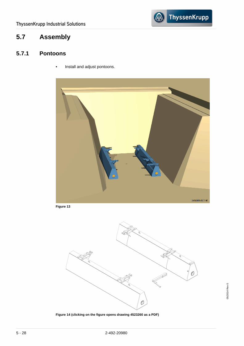
05/2
014
Rev
0
ThyssenKrupp�Industrial�Solutions
5.7 Assembly
5.7.1 Pontoons
• Install and adjust pontoons.
Figure 13
Figure 14 (clicking on the figure opens drawing 452 3260 as a PDF)
5 - 28 2-492-20980

05/2
014
Rev
0
ThyssenKrupp�Industrial�Solutions
5.7.2 Discharge conveyor
• Install and adjust the reversing station, bend pulley and part 1 of the conveyor frame.
• For assembly, see the documentation of the discharge belt.
Figure 15
2-492-20980 5 - 29

05/2
014
Rev
0
ThyssenKrupp�Industrial�Solutions
5.7.3 Discharge Hopper Platform
• Pre-assemble and fix the discharge hopper platform (1), set it on the pontoons and weld it.
• Mount the platform plankings (2).
• Assemble the railing (3).
Figure 16
5 - 30 2-492-20980

05/2
014
Rev
0
ThyssenKrupp�Industrial�Solutions
������
�� �����������
�#��
Figure 17 (clicking on the figure opens drawing 461 4138 as a PDF)
�
��������
���������� �!"�
#���� ������ � ���
$������ ������ �� ���%��������
�&���'���������� �'�� �
� ������(������������ �
�
���� �����&)�*�$������ � �
���������
+�&�,��������� ����� ����,���
��$�
%&�'"
�
��
�
��
��
��
-
-
���� ����!
���� ��!
���� ����.
���� ��.
���� ����-
���� ����"
���� ��"
���� ����/
���� ��/
���� ����
���� ��
���� ����0
���� ��0
���� ����1
���� ��1
���� ����2
���� ��2
���� ����!3
���� ��!3
���� ����!!
���� ��!!
���� ����!.
���� ��!.��#����"
�
�
�
�
#
!
�#����
�#�����
�#�����
�#�����
�#�����
����� �
��
��
��
�#����#
�����!�
��#�� #��
2-492-20980 5 - 31

05/2
014
Rev
0
ThyssenKrupp�Industrial�Solutions
5.7.4 Support and Bracing (bottom shell)
• Pre-assemble and fix the support and bracing (bottom shell) (1)
• Level and adjust the heights of the head plates,
• and guy the struts (2).
• Install steps with railing on the discharge conveyor platform (3).
Figure 18
5 - 32 2-492-20980

05/2
014
Rev
0
ThyssenKrupp�Industrial�Solutions
Figure 19 (clicking on the figure opens drawing 461 4170 as a PDF)
Figure 20 (clicking on the figure opens drawing 460 2552 as a PDF)
�������� ��
2-492-20980 5 - 33

05/2
014
Rev
0
ThyssenKrupp�Industrial�Solutions
5.7.5 Bottom shell of the discharge conveyor
• Assembly the bottom shell of the discharge conveyor (Discharge Hopper Lower Walls).
Figure 21
INFORMATION
Use the lateral filler plates.
5 - 34 2-492-20980
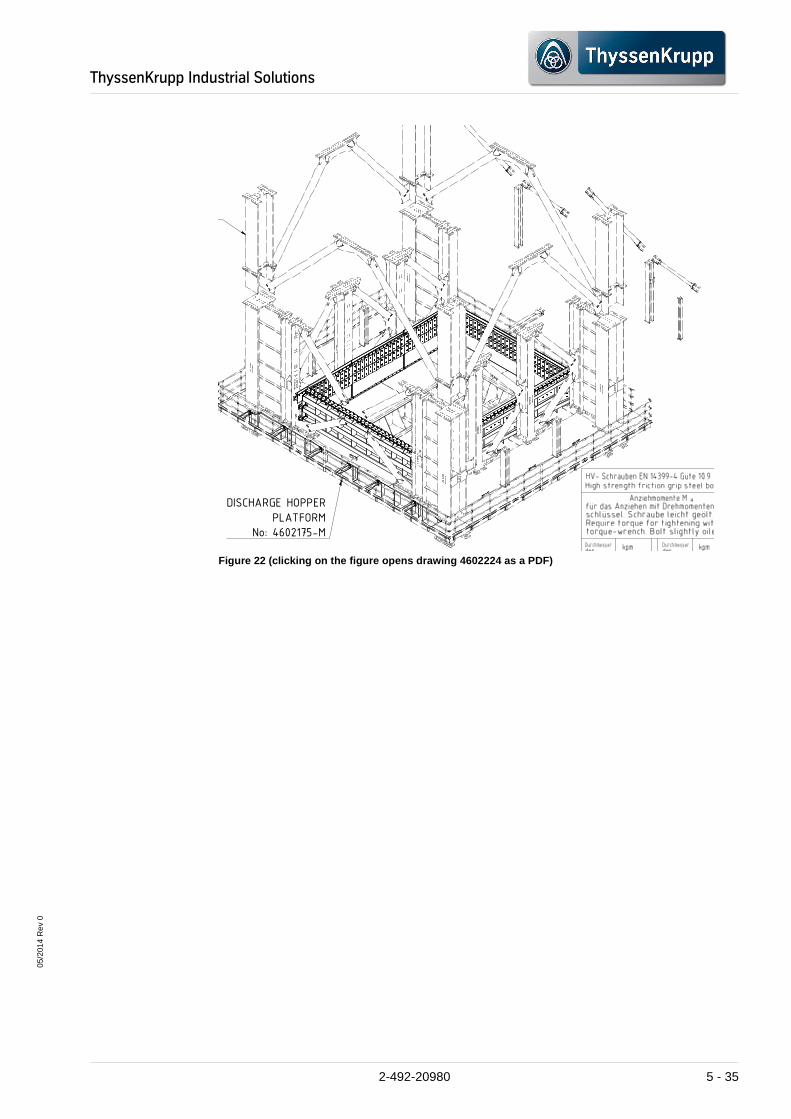
05/2
014
Rev
0
ThyssenKrupp�Industrial�Solutions
�$����������
Figure 22 (clicking on the figure opens drawing 460 2224 as a PDF)
�������� �����
��������
��� ���������
������� ���
��������
��� ���������
��������������������#�� !"���������
��
++++6666%%%%
"""",,,,��������1111$$$$����������������CCCC������������������������%%%%����������������������������%%%%))))%%%%��������������������3333
++++6666%%%%
������������####,,,,������������####((((���� ������������$$$$&&&&----��������####������������������������''''����HHHH####����((((9999����IIII&&&&��������������������))))����IIII&&&&��������""""))))����������������''''������������������������''''����////������������
����DDDD3333���� ������������$$$$&&&&----����������������....���� ����������������3333������������,,,,������������ ����((((������������''''����������������������������''''������������""""��������������������))))��������''''��������6666��������������������####����----))))####�
��������CCCC������������%%%%))))%%%%��������������������==== $$$$
����))))����IIII&&&&����3333////��������������������((((��������))))####������������####����''''��������####BBBB����))))����####����1
���� ���� ����$$$$&&&&----����1111������������&&&& ���� ��������%%%%������������������������&&&&���� ��������%%%%���������������� ����
���� �������� $$$$&&&&----����1111��������
2-492-20980 5 - 35

05/2
014
Rev
0
ThyssenKrupp�Industrial�Solutions
5.7.6 Maintenance platform
• Maintenance platform (1, Figure 23) pre-assemble and align then fix and weld according to the assembly drawings.
• Adjust and assemble the platform plankings (2, Figure 23) and railings (3).
Figure 23
5 - 36 2-492-20980

05/2
014
Rev
0
ThyssenKrupp�Industrial�Solutions
Figure 24 (clicking on the figure opens drawing 461 4162 as a PDF)
Figure 25 (clicking on the figure opens drawing 461 4164 as a PDF)
���������������� ��
$
)()()
)()(&
�
�
�
�
���������
������
������������ ����� �����
����� �������������������
������������� ������������
������������ ����� �����
����� �������������������
������������� ������������
�����������������������������
��������������� �!"##�
����� �������������������
������������� ������������
����$���� ���%����&��
������ ��������'����
�����������������������������
��������������� �!"#���
����� �������������������
������������� ������������
����$���� ���%����&��
������ ��������'���
��
��
��
��
������������#
����������#
������������#
����������#
������������#
����������#
����������#
���������(
������
���������)
������ ���������*
������
���������#
������
���������"
������
����������
������
���������(
������
���������!
������
���������#
������
��
��
��
���������)
������
��
���������
������
����������
������
���������*
������
����������
������
���������
������
���������
������
+��%,-���������"
������
+��%,-���������##
������
+��%,-���������#�
������
+��%,-���������#
������
���������#�
������
���������#!
������
���������#*
������
2-492-20980 5 - 37
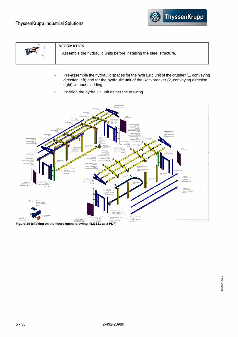
05/2
014
Rev
0
ThyssenKrupp�Industrial�Solutions
• Pre-assemble the hydraulic spaces for the hydraulic unit of the crusher (1, conveying direction left) and for the hydraulic unit of the Rockbreaker (2, conveying direction right) without cladding.
• Position the hydraulic unit as per the drawing.
Figure 26 (clicking on the figure opens drawing 452 3321 as a PDF)
INFORMATION
Assemble the hydraulic units before installing the steel structure.
Z ( 1 : 10 )
Z
B
C
D
E
F
G
H
I
J
K
Welds
external findings DIN EN 25817
non-destructive testing DR 10.01
machined surfacesGeneral tolerances for
welded assembliesGeneral tolerances for
DIN EN ISO 13920 tolerance class
DIN ISO 2768 part 1/2 tolerance classTolerances
assessment category
assessment category
ISO 8015
Welded assembly 2
4523321
LxBxH 2747x875x135
154,1 kg
Welded assembly 17
4523321
LxBxH 2747x875x135
154,1 kg
LxBxH 2747x875x85
152,0 kg
Welded assembly 10
4523321
LxBxH 2747x875x85
152,0 kg
Welded assembly 16
4523321
Welded assembly 14
4523321
Welded assembly 1
4523321
Welded assembly 15
4523321
Welded assembly 3 (12x)
4523321
LxBxH 1490x140x195
33,3 kg
Welded assembly 3
4523321
Welded assembly 3
4523321
Welded assembly 3
4523321
Welded assembly 4 (11x)
4523321
LxBxH 1425x140x195
32,3 kg
Welded assembly 5 (6x)
4523321
LxBxH 3075x140x195
64,8 kg
Welded assembly 4
4523321
Welded assembly 5
4523321
Welded assembly 4
4523321
Welded assembly 4
4523321
Welded assembly 6 (6x)
4523321
LxBxH 2730x920x300
194,5 kg
Welded assembly 14 (2x)
4523321
LxBxH 2537x2907x100
273,6 kg
Welded assembly 1 (2x)
4523321
LxBxH 2537x2907x100
273,6 kg
Doorway (2x)
4523321 item 102
DIN 18100-1125x2125
Welded assembly 15 (2x)
4523321
LxBxH 2862x220x90
75,0 kg
Welded assembly 16 (2x)
4523321
LxBxH 2862x220x90
75 kg
Welded assembly 6
4523321
Welded assembly 7
4523321
LxBxH 2730x920x300
194,5 kg
Welded assembly 8
4523321
LxBxH 2730x920x220
190,6 kg
Welded assembly 9
4523321
LxBxH 7460x2406x160
457,1 kg
Welded assembly 11 (8x)
4523321
LxBxH 2842x220x220
176,4 kg
Welded assembly 11
4523321
Welded assembly 11
4523321
Welded assembly 11
4523321
Welded assembly 11
4523321
Welded assembly 11
4523321
Welded assembly 11
4523321
Welded assembly 11
4523321
Welded assembly 12
4523321
LxBxH 8800x140x140
298,4 kg
Doorway
4523321 item 101
Doorway
4523321 item 102
Welded assembly 13
4523321
LxBxH 1425x176x480
44,6 kg
Welded assembly 19 (8x)
4523321
LxBxH 220x305x60
10,9 kgWelded assembly 6
4523321
Welded assembly 6
4523321
Welded assembly 6
4523321
Welded assembly 6
4523321
Welded assembly 19
4523321
Welded assembly 19
4523321
Welded assembly 19
4523321
Welded assembly 19
4523321
Combined Power
4523321 item 100 (2x)
provision TKF
Combined Power
4523321 item 100 (2x)
provision TKF
Doorway (2x)
4523321 item 101
DIN 18100-1125x2125
Plate (30x)
4523321 item 2
LxBxH 190x140x5
1 kg
Profile (6x)
4523321 item 28
U 120x9970
132,9 kg
Plate (2x)
4523321 item 14
LxBxH 9970x200x10
156,1 kg
Plate
4523321 item 14
Profile
4523321 item 28
Plate (2x)
4523321 item 24
LxBxH 320x220x20
7,9 kg
Angle (4x)
4523321 item 50
L 60x60x6x85
0,4 kg
Plate
4523321 item 24
Angle
4523321 item 50
Welded assembly 9
4523321
21
10
1110
5 - 38 2-492-20980

05/2
014
Rev
0
ThyssenKrupp�Industrial�Solutions
Figure 27
2-492-20980 5 - 39

05/2
014
Rev
0
ThyssenKrupp�Industrial�Solutions
5.7.7 Discharge Hopper Upper Walls
• Pre-assemble the panels and doors
• After assembly lubricate the hinges.
• Adjust and assembly the door seals.
• Seal the columns and the corners of the entire discharge hopper (Upper and Lower Walls).
Figure 28
INFORMATION
If required, use the lateral filler plates.
5 - 40 2-492-20980

05/2
014
Rev
0
ThyssenKrupp�Industrial�Solutions
Figure 29 (clicking on the figure opens drawing 452 3291 as a PDF)
• Align, adjust and assemble the pre-assembled hydraulic spaces.
Figure 30
( 1 : 50 )
Werkstückkanten ohne Angaben nach DIN 6784Chamfers w/o dimension acc to DIN 6784
Außengewinde bis auf Kern- n Innengewinde
Außenkanteouter edges
vereinfach.
inner edges-0,3-0,5 Innenkante
+0,3+0,5
=
x = Rz=100
average roughness Rzvalue acc to EN-ISO
gemittelte Rauhtiefe RzEintragung
symbolssimplified
EN-ISO 1302
1302
The reproduction, distribution and utilization of this
document as well as the communication of its con-
tents to others without explicid authorization is
prohibited. Offenders will be held liable for the
payment of damages. All rights reserved in the event
of the grant of a patent, utility model or design.
Weitergabe sowie Vervielfältigung diese Dokuments,
Verwertung und Mitteilung seines Inhalts sind ver-statics
reviewed
dept..
Welds
extern
non-de
Werkstoff/Mater
Maßstab/Scale
Stückl.-Nr.:
list o. Mat.
KN 912235.11
edited.
EN ISO 1302
NameDate
D
Surface
machined surfacesGeneral tolerances for
welded assembliesGeneral tolerances for
DIN EN ISO 13920 tolerance class
DIN ISO 2768 part 1/2 tolerance classTolerances
No. of features
Oberfläce
Dischupper pa
09.08.2012 We/AUN
2-492-20980 5 - 41

05/2
014
Rev
0
ThyssenKrupp�Industrial�Solutions
5.7.8 Crusher platform
• Pre-assemble, fix and weld the platform parts.
Figure 31
INFORMATION
Adhere to the welding sequence and the specifications for welding.
5 - 42 2-492-20980

05/2
014
Rev
0
ThyssenKrupp�Industrial�Solutions
Figure 32 (clicking on the figure opens drawing 461 4172 as a PDF)
• Assemble the drive platform.
Figure 33 (clicking on the figure opens drawing 460 2299 as a PDF)
����
����
����
�
�' �(3�"� #+" �$"3�+$�$
($, ,�� "� � % *""�$2
�(+�$% !���'4 5
&#��"�#$�$% !$, .� ,�$%/
"�!$ �& �""�, 0��� �������12
��'#6� !" ��,� !$, %+�$, �6�
Package gratings
4602299 Item 12
total weight 929,2 kg
Plate
4602299 Item 28
LxBxH 500x408x30
32,2 kg
Plate
4602299 Item 28
Steelwork WA 1
4602299
LxBxH 8720x4475x1115
6774,0 kg
teelwork WA 2
4602299
H 2018x2110x780
173,6 kg
Wind Bracing
4602299 item 8,9
Wind Bracing (2x)
4602299 item 8,9
n 139,7x6,3x2588
55,0 kg
Plate
4602299 Item 3
Plate (2x)
4602299 Item 3
LxBxH 740x608x20
56,0 kg
Steelwork WA 3
4602299
LxBxH 2018x2110x780
173,6 kg
2-492-20980 5 - 43

05/2
014
Rev
0
ThyssenKrupp�Industrial�Solutions
• Adjust and assemble the platform plankings and the railing on the drive platform.
Figure 34 (clicking on the figure opens drawing 461 4186 as a PDF)
�����������
��� ��
���������������
�����
�����������
��� �
���������������
�����
�����������
��� �
����������������
�����
�����������
��� �
������� ��������
������
�����������
��� �
����������������
�����
�����������
��� �
��������� ������
�����
�����������
��� �
���������������
�����
����������
��� �
����� ���������
�����
�����������
��� �
������ ��������
����
�����������
��� �
�����������������
�������
5 - 44 2-492-20980

05/2
014
Rev
0
ThyssenKrupp�Industrial�Solutions
Figure 35
2-492-20980 5 - 45

05/2
014
Rev
0
ThyssenKrupp�Industrial�Solutions
��������
���
!� ���"��#����
!� ���"��#����"(�"�
!� �
���������������������������#���$�7����
• Adjust and assemble the platform plankings and the railing on the crusher platform.
Figure 36
Figure 37 (clicking on the figure opens drawing 461 4185 as a PDF)
�� ��������������
������������������
�� �������������
��������������������������
�� ��������������
��������������������������
�� ��������������
��������������������������
�&�
��
���
���
���
��!
���
���
���
��
��%
���
����
����
!� ���"��#����"(�"�)����
!� ���"��#����"(�"�)����
!� ���"��#����"(�"�)����
!� ���"��#����"(�"�)�
!� ���"��#����"(�"�)����
!� ���"��#����"(�"�)����
!� ���"��#����"(�"�)����
"(�"�)����
)����
��"��#����"(�"�)����
!� ���"��#����"(�"�)����
������%������������
�������������������
����
5 - 46 2-492-20980

05/2
014
Rev
0
ThyssenKrupp�Industrial�Solutions
5.7.9 Support and Bracing (top part)
• Measure, pre-assemble, fix and weld the steel structure. here, pay attention to the position and height of the head plates.
Figure 38
Figure 39 (clicking on the figure opens drawing 461 4170 as a PDF)
�������� ��
2-492-20980 5 - 47

05/2
014
Rev
0
ThyssenKrupp�Industrial�Solutions
���()��������
���()������ �
���()������ '
������������������������
���()��������
������������������������
�&���'� �����������'
����������������������������
������������������������������������
��������������������������� �
5.7.10 Maintenance platform
• Assemble the maintenance platform (1, Figure 42).
• Install the steps.
• Assemble the platform plankings and the railing.
Figure 40 (clicking on the figure opens drawing 461 4158 as a PDF)
• Assemble and align the steps (2, Figure 42).
��
��
��
��
����DDDD3333���� ������������$$$$&&&&----����������������....���� ����������������3333������������,��������''''����������������������������''''������������""""��������������������))))��������''''��������6666�����
�����������
�����������
������
'����
'����
����
�'�
'����
'�
����
'����
'����
'�����
�
�$23�4$��%�����$��,*����2��+���4�52,,��$�!"���+�%�4��-��+� �� ����
��"2#���%�*�$$2-,�/
��������
���������
���������
���������
��������
�������� ���������
��������!
��������
��������
���������
5 - 48 2-492-20980

05/2
014
Rev
0
ThyssenKrupp�Industrial�Solutions
Figure 41 (clicking on the figure opens drawing 460 2558 as a PDF)
Figure 42
Graiting
g G4
60
4620x2050x1210
kg
2-492-20980 5 - 49

05/2
014
Rev
0
ThyssenKrupp�Industrial�Solutions
���
5.7.11 Feed hopper and panels
Assemble the feed hopper (1, Figure 44) in the following sequence:
• Pre-assemble, fix and weld the hopper base.
• Screw the hopper modules,
• adapt, fix and weld the side panels.
• Assemble the support for the "Main Shaft Stands."
• Lift, adjust and screw 4 hopper parts on the scaffold.
• Assemble the side walls (2, Figure 44).
Figure 43 (clicking on the figure opens drawing 461 4191 as a PDF)
��
�
�
��
�
�
�
��
"�#"#'�
"�#"#''
"&$(()#
�+������,��!�� ��������
5 - 50 2-492-20980

05/2
014
Rev
0
ThyssenKrupp�Industrial�Solutions
Figure 44
• Fasten the dust sealing and dust chute at the crusher inlet opening.
INFORMATION
Assemble the splitter only after installing the crusher.
2-492-20980 5 - 51
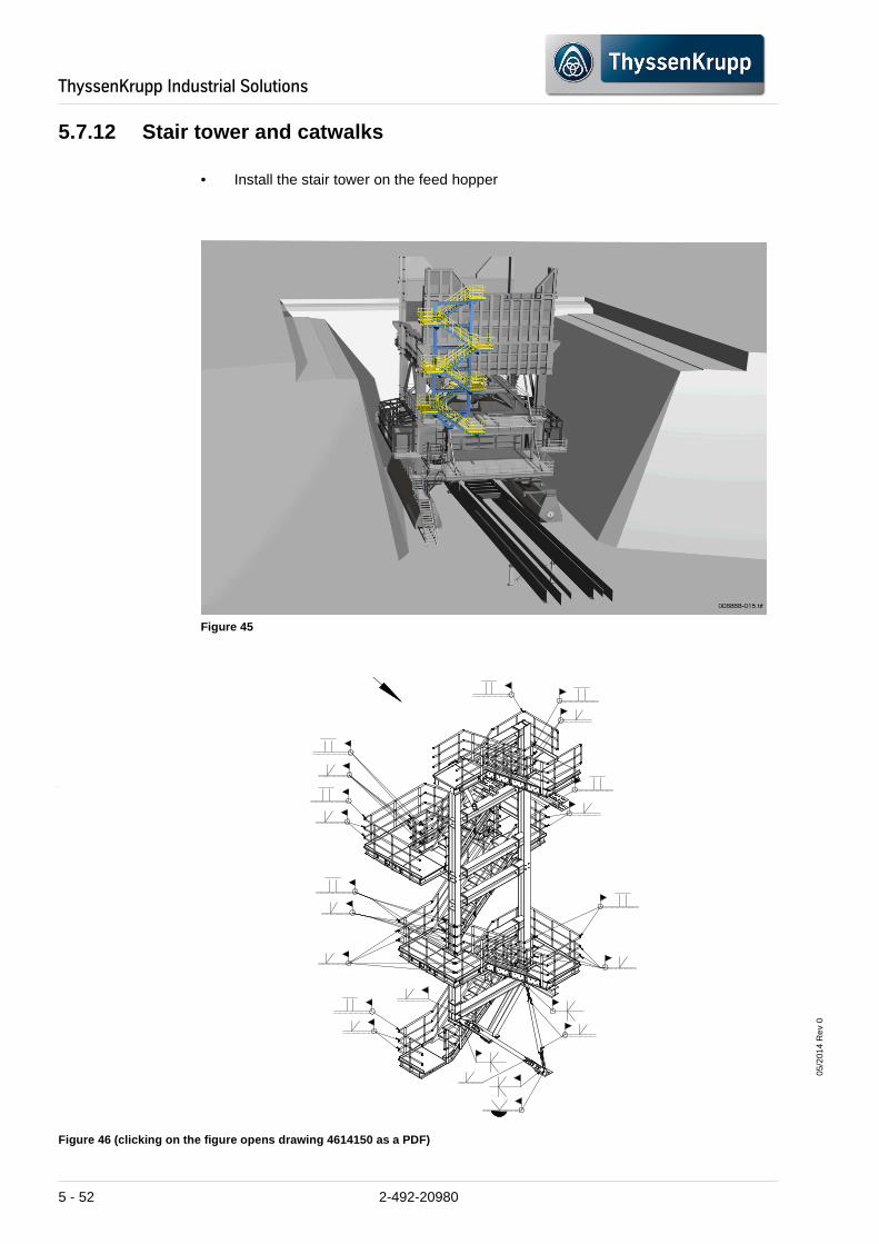
05/2
014
Rev
0
ThyssenKrupp�Industrial�Solutions
5.7.12 Stair tower and catwalks
• Install the stair tower on the feed hopper
Figure 45
Figure 46 (clicking on the figure opens drawing 461 4150 as a PDF)
5 - 52 2-492-20980

05/2
014
Rev
0
ThyssenKrupp�Industrial�Solutions
Attach catwalk to dedusting and also:
• Assemble the bearing frame,
• Assemble the steps and platforms,
• Assemble and install the transitions to the individual platforms.
Figure 47
Figure 48 (clicking on the figure opens drawing 461 4155 as a PDF)
��������
���� ���� ���� ���� ���� �
����
����
���$��
! ����������� ������)������)� �*����+,-�#&&�������* �������������������������� ������ �,�.�#&'&
�
2-492-20980 5 - 53
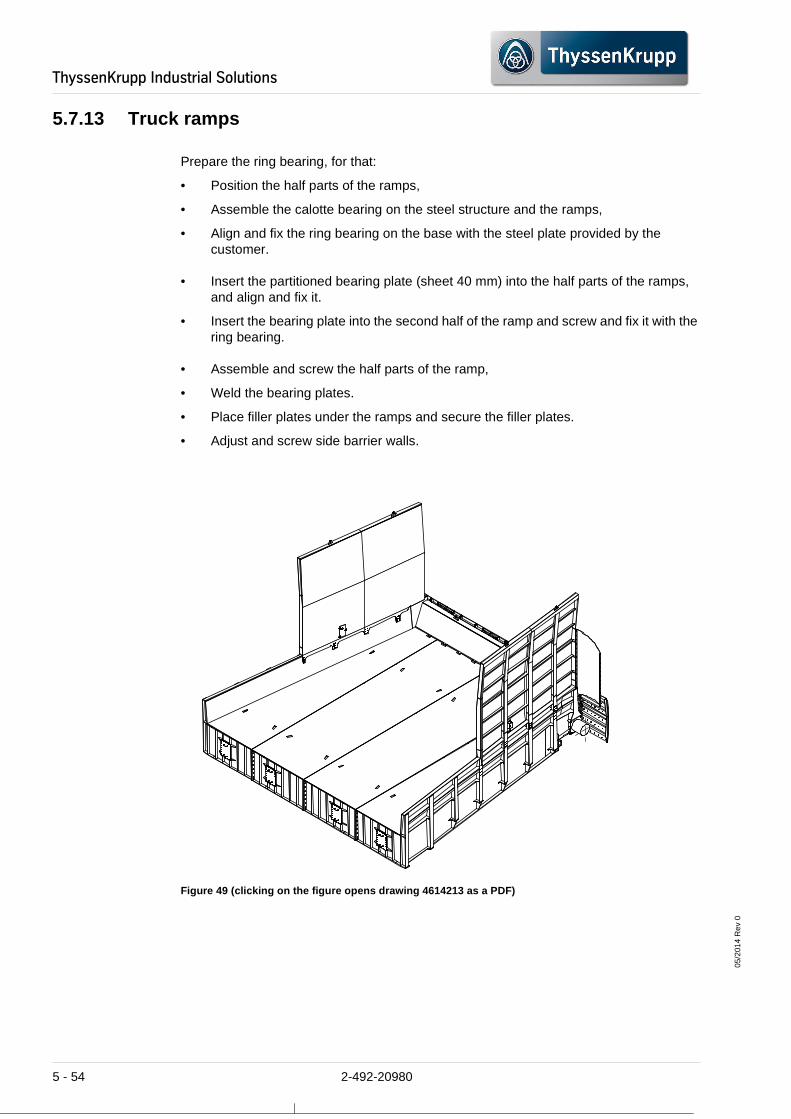
05/2
014
Rev
0
ThyssenKrupp�Industrial�Solutions
5.7.13 Truck ramps
Prepare the ring bearing, for that:
• Position the half parts of the ramps,
• Assemble the calotte bearing on the steel structure and the ramps,
• Align and fix the ring bearing on the base with the steel plate provided by the customer.
• Insert the partitioned bearing plate (sheet 40 mm) into the half parts of the ramps, and align and fix it.
• Insert the bearing plate into the second half of the ramp and screw and fix it with the ring bearing.
• Assemble and screw the half parts of the ramp,
• Weld the bearing plates.
• Place filler plates under the ramps and secure the filler plates.
• Adjust and screw side barrier walls.
Figure 49 (clicking on the figure opens drawing 461 4213 as a PDF)
5 - 54 2-492-20980

05/2
014
Rev
0
ThyssenKrupp�Industrial�Solutions
• Attach catwalk truck ramp with railings and coverings onto the ramp.
Figure 50
2-492-20980 5 - 55

05/2
014
Rev
0
ThyssenKrupp�Industrial�Solutions
5.7.14 Catwalk view (1)
Attach catwalk, and also:
• Assemble the bearing frame,
• Assemble the steps and platforms,
• Assemble and install the transitions to the individual platforms.
Figure 51 (clicking on the figure opens drawing 461 4151 as a PDF)
�������������
���
���
���
��
���
���
���
������ ����
���
���
���
���
���
�
������ ���
�
������ ���
#���$����&'������(�
���������&'������(�
��%�������)*'����+
��������������
��������������
5 - 56 2-492-20980

05/2
014
Rev
0
ThyssenKrupp�Industrial�Solutions
Figure 52
2-492-20980 5 - 57

05/2
014
Rev
0
ThyssenKrupp�Industrial�Solutions
5.7.15 Rockbreaker support (4)
• Pre-assemble, fix and weld the steel structure
• and assemble on the rear of the hopper.
• Align and fix the upper platform for work on the rockbreaker.
• Assemble the railing and the plankings.
• Align and secure the lower platform.
• Assemble the railing and the plankings.
Attach the catwalk rockbreaker (2), and also:
• Assemble the bearing frame,
• Assemble the steps and platforms,
• Assemble and install the transitions to the individual platforms.
Figure 53 (clicking on the figure opens drawing 461 4228 as a PDF)
����������
$� �%�&�# ����' �# (��(��,
-�� � �� � �# �
-� �-� )
-� (
5 - 58 2-492-20980

05/2
014
Rev
0
ThyssenKrupp�Industrial�Solutions
Figure 54
2-492-20980 5 - 59

05/2
014
Rev
0
ThyssenKrupp�Industrial�Solutions
5.7.16 Main shaft stand (3)
• Assemble, fix, and weld the structural steel on the installation location,
• Assemble the railing and the plankings.
Figure 55 (clicking on the figure opens drawing 461 4154 as a PDF)
����
����
����
����������������!���
�����������������!���
5 - 60 2-492-20980

05/2
014
Rev
0
ThyssenKrupp�Industrial�Solutions
Figure 56
2-492-20980 5 - 61

05/2
014
Rev
0
ThyssenKrupp�Industrial�Solutions
5.7.17 Rockbreaker and crusher
• Refer to the specific documentation of the components for the assembly of rockbreaker and the crusher.
Figure 57
5.7.18 Electro-housing
• Assemble and secure the steel construction for the electro-housing.
• Assemble the steel construction for the operator cab.
• Assemble the access platforms with handrails and coverings.
• Assemble the access platforms, railings and stairs.
• Install the transformers, electric container and operator's cab.
5 - 62 2-492-20980

05/2
014
Rev
0
ThyssenKrupp�Industrial�Solutions
Figure 58 (clicking on the figure opens drawing 461 4187 as a PDF)
5.7.19 Periphery
• Place the drive for the gyratory crusher on the drive platform and connect to the cone crusher.
• Assemble the maintenance car with scissors lift.
5.7.20 Continuation discharge belt
• Assemble and align part 2 of the belt frame.
• Assemble and align the drive station and the driving pulley.
• For assembly, see the documentation of the discharge belt.
�
�
������������ �
������������
���������
�������������
���������
��������������
���������
�������
�������
���
��
�
�
�������
�!" ��" �#
���
�����$��%
�&�
���
2-492-20980 5 - 63

ThyssenKrupp�Industrial�Solutions
05/2
014
Rev
0
Blank page
5 - 64 2-492-20980

05/2
014
Rev
0
ThyssenKrupp�Industrial�Solutions
6 Commissioning and operation
6.1 General information
For many reasons we highly recommended you call for the assistance of ThyssenKrupp Resource Technologies staff in the commissioning process. This is not only for reasons relating to the warranty, but also for the purpose of:
• having the machine/plant checked
• determining the optimum capacity
• training the operating personnel
• passing on additional advice on operation, maintenance and upkeep.
For the initial commissioning routine note the instructions relating to the components
– APPENDIX 8.2 "Gyratory crusher"
– APPENDIX 8.3 "Discharge conveyor"
– APPENDIX 8.6 "Hydraulic hammer/rockbreaker"
– APPENDIX 8.7 "Sprinkling system with desalination"
.
2-492-20980 6 - 1

05/2
014
Rev
0
ThyssenKrupp�Industrial�Solutions
6.2 Operator training
These installation and operation instructions to operate the machine/plant does not replace training and instructions. Previous technical and safety knowledge is required for operation of the machine/plant!
The owner must prepare a directive for regulating the internal operation, maintenance and repair of the machine/plant.
These installation and operation instructions include the requisite operating instructions for the operating personnel. Always make sure to observe the intended use of the machine/system (see Chapter 4.1).
The operating staff must be familiar with the arrangement and function of the safety devices.
6.3 Safety instructions for operation
DANGER
Risk of injury from damaged insulation on the conne cting cable and missing terminal box covers
Imminent danger of death or severe bodily injuries
• The electrical connections to the drives must be adequately protected.
WARNING
Risk of injury from larger oscillation amplitudes
Death or severe bodily injury is possible.
• Do not reach into the spaces between fixed components and oscillating components.
• Repair incorrect oscillation before feeding material.
6 - 2 2-492-20980

05/2
014
Rev
0
ThyssenKrupp�Industrial�Solutions
• Operate the machine / plant only if all protective and safety-oriented devices, such as removable safety devices and emergency shut-off equipment, sound-proofing elements and exhausters, are in place and fully functional!
• Check the machine/ plant at least once every shift for obvious damage and defects! Report any changes (including changes in the operating performance) to the responsible department immediately! If necessary, stop the machine/ plant immediately and lock it!
• In the event of malfunctions, stop the machine/ plant immediately and lock it! Have any defects remedied immediately!
• Follow the start-up and shutdown procedures and control displays as set out in the manual!
• Before starting up/putting the the machine/ plant into operation, make sure that nobody is at risk!
• If abnormal vibrations suddenly occur in the equipment supporting structure the operation of which is corresponding with vibrations and unbalances, these abnormal vibrations must be eliminated prior to feeding the machine with material.
• Only work with the prescribed lighting under darkness and with poor visibility.
• Switch off the plant/machine immediately if people are at risk, e.g. due to careless working near belt conveyor systems and material transfer points.
• Local operation of individual drives is allowed only during inspection, maintenance and repair work.
• Work may only be carried out if the worker is properly qualified and/or has been authorised to do so. Do not carry out maintenance and repair work without authorization.
CAUTION
Risk of injury when operating the drive units witho ut protective clothing
Bodily injury possible
• The machine must never be operated without the guards in position over the drive units.
2-492-20980 6 - 3

05/2
014
Rev
0
ThyssenKrupp�Industrial�Solutions
6.4 Power supply and control system
Power is supplied via mains and feeder circuits.
Gyratory crushers may only be operated in an electrically interlocked condition for safety reasons and as a protection against overloading.
The start-up and shutdown procedures of the gyratory crusher and the upstream and downstream units/equipment must be executed in a defined sequence for functional and safety reasons. To this end, the crusher and these units are electrically interlocked internally and with each other. The control system, all drives as well as the monitoring devices/local transmitters connected to the control system are included in the interlocking system. Any faults are signalled to the control station/control cabin. Depending on the type of failure, only a message is output or the upstream units/the crusher are switched off.
The drives can also be operated separately, i.e. locally, for inspection, maintenance and repair work as well as for test runs.
GYRAMATIC is a compact and reliable control and monitoring system that has been specially designed for the ThyssenKrupp gyratory crusher. It provides all the control functions as regards operation, calibration and overloads which are necessary for reliable and problem-free operation of the gyratory crusher. The device is designed as a touch screen terminal and enables control and gearing of all motors connected to the gyratory crusher. Here, the pressure, temperature and oil flow in the lubricant/hydraulic system and in the hydraulic system of the automatic traverse tension are displayed.
NOTICE
System damage through use of the machine/plant cont rary to its designated use
Damage to the machine/plant or its environment is possible
The intended use of the machine/plant is regulated by contract. Any other use contrary to its designated use is prohibited. ThyssenKrupp Resource Technologies cannot be held liable for damage resulting from such misuse. The risk of such misuse lies entirely with the user.
• Electrical interlocking systems may only be switched off by qualified personnel. All drives must be interlocked during normal operation!
INFORMATION
The safety-related parts of control systems for the gyratory crusher meet the required Performance Level "D" - Category 2 . The delivery scope of ThyssenKrupp Resource Technol ogies-Busines Unit Processing does not include the control unit "MCC," but only the GYRAMATIC.
6 - 4 2-492-20980

05/2
014
Rev
0
ThyssenKrupp�Industrial�Solutions
6.5 Shutting down
6.5.1 Normal operation
The material feed must always be interrupted before the crushing plant is stopped. The crushing plant can then run "empty."
When the crushing plant is stopped, make sure that sufficient material remains in the feed hopper to protect the conveyor covering.
6.5.2 Emergency-stop system
Several emergency-stop switches must be installed on the machine/plant.
The emergency-stop switches are identified by red impact surfaces on yellow background.
The switches engage on actuation.
NOTICE
Plant damage through false material feeding after e mptying the feed conveyor
Damage to the machine/plant or its environment is possible
• If the feed hopper is run empty, ensure that small-sized pieces of material are again initially fed to the feed hopper when material feeding resumes. This serves to protect the conveyor covering against the impact load of lump material.
NOTICE
System damage from material overfilling when using emergency-stop switch
Damage to the machine/plant or its environment is possible
When using an emergency-stop switch, there is a danger of material overfilling at the transfer points, as all upstream and downstream parts of the plant are switched off with no specific shutdown sequence.
• The emergency-stop switches must not be used for normal shutdown.
2-492-20980 6 - 5

05/2
014
Rev
0
ThyssenKrupp�Industrial�Solutions
• The whole electrical system is switched off by the emergency stop.
• Ascertain the danger or damage, and provide first aid if necessary.
• Have any defects rectified.
• In order to restart the plant after having rectified the emergency case, the actuated switch is to be unlocked by turning the impact surface to the right-hand side.
• Acknowledge the fault.
• Switch the main electrical supply back on.
6 - 6 2-492-20980
05/2
014
Rev
0
ThyssenKrupp�Industrial�Solutions
7 Maintenance
7.1 Important information on maintenance
The following activities may only be carried out by qualified personnel:
• Note the information in the Operating Instructions on adjusting, maintenance and inspection work and observe the intervals set out, including information on the replacement of parts and equipment!
• Inform the operating personnel before starting service and maintenance work! Appoint a person to supervise the work!
• When carrying out any work concerning the operation, conversion or adjustment of the machine/ plant and its safety-oriented devices or any work related to maintenance, inspection and repair, always follow the start-up and shutdown procedures described in the Operating Instructions and the information on maintenance work!
• As a general principle, all work on the machine/ plant should only be carried out when the machine/ plant is at a standstill.
If the machine/ plant has been completely shut down for maintenance and repair work, it must be secured against inadvertent restart by:
• Locking the principal control elements and removing the ignition key and/ or
• attaching a warning sign to the main switch.
• Before restarting the machine/plant after repair work, check that all safety devices have been attached.
• After electrical installation or repair work, test the protection systems (e.g. earth resistance) used.
WARNING
Risk of injury through cleaning, inspection, mainte nance and repair work during operation
Death or severe bodily injury is possible.
• Cleaning, inspection, maintenance and repair work may only be carried out when the machine/plant is switched-off and secured against restarting.
• Do not get into the machine/plant's interior unless it is supplied with fresh air and has sufficiently cooled down. Make sure that there is enough oxygen in the interior and that no hot gas can get in.
• The machine/plant’s interior must continuously be fed with fresh air during works (by blowing-in or exhausting) thus keeping the inhaled air free from components injurious to health. Do not ventilate with pure oxygen. Wear dust protective masks in case of possible dust formation.
2-492-20980 7 - 1

05/2
014
Rev
0
ThyssenKrupp�Industrial�Solutions
• To avoid the risk of accidents, individual parts and large assemblies being moved for replacement purposes should be carefully attached to lifting gear and secured. Only use suitable and technically perfect lifting gear and suspension systems with an adequate carrying capacity! Never work or stand under suspended loads!
• The fastening of loads and the instruction of crane operators should only be entrusted to experienced persons! The marshaller must be within eyesight of the operator or have verbal communication with him.
• When carrying out overhead assembly work, always use specially designed or other suitable and safe climbing aids and working platforms. Never use machine parts as a climbing aid! Wear fall protection when carrying out maintenance work at a higher level.
• Keep all handles, steps, handrails, platforms, landings and ladders free of dirt, snow and ice!
• Always tighten up any bolted connections which have been loosened during maintenance and repair work!
• Any safety devices removed for setting up, maintenance or repair purposes must be refitted and checked immediately upon completion of the maintenance and repair work.
• Ensure that all consumables and process materials and replaced parts are disposed off safely and in an environmentally friendly manner!
• Only use original fuses with the specified current rating! Shut down the machine/ plant immediately if faults occur in the electrical power supply!
• Work on the electrical system or equipment may only be carried out by a skilled electrician or by specially instructed personnel under the control and supervision of a skilled electrician and in accordance with the applicable electrical engineering rules.
• If prescribed, the power supply to parts of machines and plants on which inspection, maintenance and repair work is to be carried out must be disconnected. Check that the isolated parts have been disconnected from the supply, then earth and short-circuit them and insulate any adjacent live parts!
• The electrical equipment of the machine/plant must be inspected at regular intervals. Any defects such as loose connections or scorched cables must be rectified immediately.
• If work on live parts is necessary, it may only be carried out in the presence of a second person who can disconnect the power supply in an emergency by actuating the emergency stop button or main power switch. Cordon off the working area with a red-and-white safety chain and a warning sign. Only use insulated tools!
• Before starting work on high-voltage assemblies and after disconnecting the power supply, the supply cable must be earthed and components such as capacitors short-circuited with an earthing rod!
• Carry out welding, flame-cutting and grinding work on the machine/ plant only if this has been expressly authorised, as there may be a risk of explosion and fire!
7 - 2 2-492-20980

05/2
014
Rev
0
ThyssenKrupp�Industrial�Solutions
• Before carrying out welding, flame-cutting and grinding work, clean dust and other inflammable substances from the machine/ plant and its surroundings and provide adequate ventilation (risk of explosion)!
• Check all lines, hoses and bolted connections regularly for leaks and obvious damage. Repair any damage immediately! Splashing oil may cause injury and fires.
• Depressurise all system sections and pressure pipes which are to be opened in accordance with the instructions for the assembly group concerned before carrying out any repair work!
• Hydraulic lines must be laid and connected in line with good professional practice! Do not mix up any exchange connections! The fittings, lengths and quality of the hoses must comply with the technical requirements.
• Follow the applicable safety regulations when handling oil, grease and other chemical substances!
• Be careful when handling hot consumables and process materials (risk of burning or scalding)!
7.1.1 Notes on cleaning
• Check the degree of soiling of the machine/plant every day. Do not allow material to accumulate or cake. The mechanical interaction of the plant components may be interfered with and malfunctions and increased wear occur.
• Always clean the assembly group in question before commencing maintenance work.
• Before cleaning the machine/ plant with water or steam jet (high-pressure cleaners) or other cleaning agents close/tape up all openings into which water, steam and detergents should not be allowed to penetrate for safety or operational reasons. Electric motors and switch cabinets are at particular risk.
• Do not use corrosive detergents.
• Do not direct the spray jet at electrical devices, relay boxes and switch cabinets, intake and breather filters or greased surfaces.
CAUTION
Risk of injury when working without personal safety equipment
Bodily injury possible
• Always wear a face protector when carrying out cleaning work with high-pressure or steam jet cleaners.
2-492-20980 7 - 3
05/2
014
Rev
0
ThyssenKrupp�Industrial�Solutions
• Always hold the spray jet a sufficiently large distance away from the surface being cleaned and do not direct the spray jet at these surfaces at right angles.
• Clean places which are difficult to reach with suitable equipment e.g. special brooms.
• The covers and adhesions must be removed completely after cleaning.
• After cleaning, check all lubricant and hydraulic oil lines for leaks, loose connections, friction areas and damage! Eliminate any deficiencies immediately!
7.1.2 Information on maintenance and inspection
Failures arising from inadequate or improper maintenance may cause high repair costs and long downtimes. Regular maintenance is therefore indispensable.
Functional safety, trouble-free operation and the service life of the machine/ plant depend on proper cleaning, inspection and maintenance.
WARNING
Risk of injury by neglecting proper maintenance int ervals
Death or severe bodily injury is possible.
• All pending maintenance work must be completed according to schedule. The manufacturer does not accept liability for damage resulting from maintenance work which has not been carried out or has not been carried out according to schedule.
NOTICE
System damage through improper maintenance
Damage to the machine/plant or its environment is possible.
• Check the machine / plant at least once per shift for obvious damage and defects! Report any changes (including changes in the operating performance) to the responsible department immediately!
• In the event of malfunctions, stop the machine / plant immediately and lock it! Have any defects remedied immediately!
7 - 4 2-492-20980

05/2
014
Rev
0
ThyssenKrupp�Industrial�Solutions
Check the machine/ plant at the specified intervals (inspection intervals, maintenance periods) for proper operation, lubrication condition and wear.
• Replace or repair all damaged/ worn parts.
• Check the paintwork for corrosion at regular intervals but no later than every 6 months. Touch up all damaged areas in line with good professional practice.
• Have the function of all instrumentation and control devices/ electrical interlocks checked by qualified personnel at regular intervals.
The required frequency of checks for wear, inspection, maintenance and repair cannot be specified beforehand owing to the variety of service conditions. An appropriate routine inspection schedule must be prepared making allowance for the operating conditions.
The maintenance table is a guideline for inspection and maintenance work.
• For maintenance and repair work strictly follow the general safety notes included in (Chapter 3).
As recommended during commissioning you are advised to have initial repairs carried out by the personnel from ThyssenKrupp Industrial Solutions. Your maintenance staff will have the opportunity to take part in an intensive training course.
7.1.3 Notes relating to repairs
INFORMATION
Downtimes for repairs can also be used for scheduled maintenance work.
WARNING
Risk of injury due to improper fastening
Death or severe bodily injury is possible.
• Individual parts and large assemblies being moved for replacement purposes should be carefully attached to lifting gear and secured so that they do not pose any danger. Only use suitable and technically perfect lifting gear and suspension systems with an adequate carrying capacity! Never work or stand under suspended loads!
• The fastening of loads and the instruction of crane operators should only be entrusted to experienced persons! The marshaller must be within eyesight of the operator or have verbal communication with him.
• When carrying out overhead assembly work, always use specially designed or other suitable and safe climbing aids and working platforms. Never use machine parts as a climbing aid! Wear fall protection when carrying out maintenance work at a higher level.
2-492-20980 7 - 5

05/2
014
Rev
0
ThyssenKrupp�Industrial�Solutions
• Immediately replace worn components with new components. With worn components, strength is reduced and the risk of fracture is increased!
• Do not re-use seals and safety elements that have been removed.
• When re-using assembly groups and parts, always use new bolts, nuts and washers.
• Do not leave any tool or other device in the machine/plant.
• Observe the welding instructions for the prevention of accidents whenever carrying out welding work.
• During electric welding, secure the earthing cable near the part being welded. Do not route the welding current return line over movable machine elements (e.g. shafts, bearings). For bridging, fit a cable with a cross-section adequate for the strength of the welding current and for the length over which current must be carried.
• Restore the machine/plant to its original state on the completion of the repair work. Remount protective and safety devices again. Make sure that the machine/plant is working properly by carrying out a test run.
7.2 Screwed and bolted connections
Always protect all screwed and bolted connections a gainst corrosion.
7.2.1 Machine structures
For machine structures: Standard Quality
Hexagon bolt (thread up to head) DIN EN ISO 4017 8.8 / 10.9 / 12.9
Hexagon socket head cap bolt DIN EN ISO 4762 8.8 / 10.9 / 12.9
Hexagon socket head cap bolt with short head DIN 7984 8.8 / 10.9 / 12.9
Hexagon nut DIN EN ISO 4032 8 / 10 / 12
Washer DIN 6916 C 45 hardened
Hexagon fitted bolts DIN 609 8.8 / 10.9 / 12.9
Use only the following bolts and nut qualities toget her:
Screw grade: 8.8 10.9 12.9
Nut grade 8 10 12
7 - 6 2-492-20980

05/2
014
Rev
0
ThyssenKrupp�Industrial�Solutions
Tightening torques for machine structures
Calculated with µk = 0.14 (new bolts, without post-treatment) in accordance with VDI 2230
Bolt diameter
Tightening torque M A (Nm)Class
8.8 10.9 12.9
M6 11 15 18
M8 26 36 43
M10 51 71 86
M12 88 123 148
M16 211 300 358
M20 412 579 697
M24 711 1000 1196
M30 1422 2010 2403
M36 2481 3491 4197
M42 3991 5609 6727
M48 6021 8473 10150
M56 9650 13582 16279
M64 14416 20300 24320
INFORMATION
Only use the tightening torques listed in the table when no special tightening torques are indicated in the relevant section.
2-492-20980 7 - 7

05/2
014
Rev
0
ThyssenKrupp�Industrial�Solutions
7.2.2 High-tensile bolted joints
In the case of high-tensile (friction-type bolted connections), the force is transmitted by friction between the contact faces and depends on the pretensioning force of the bolts. The contact faces must be bright. They must be cleaned by sandblasting, flame cleaning or chemical detergents (DIN 18800, DIN V 18800-7 - Appendix D.1.6).
• Use bolts, nuts and washers from one manufacturer only. A uniform protection against corrosion is compelling.
• Only use properly oiled bolts in perfect condition.
• Use a torque wrench to produce the required bolt pretensioning force.
• Use the required pretensioning forces indicated in the table below or in the drawing.
Components are marked as follows
Material dataManufacturer
dataMarked HSFG
Hexagon bolt HSFG as per DIN 6914
10.9 yes HSFG
Hexagon nut HSFG as per DIN 6915
10 yes HSFG
Washer as per DIN 6916
- yes HSFG
Use only the following bolts and nut qualities toget her:
Screw grade: 10.9 12.9
Nut grade 10 12
For steel structures: Standard Quality
Hexagon bolt DIN 6914 10.9 / 12.9
Hexagon nut DIN 6915 10 / 12
Washer DIN 6916 C 45 hardened
7 - 8 2-492-20980

05/2
014
Rev
0
ThyssenKrupp�Industrial�Solutions
Pretensioning forces and tightening torques applica ble to torque methods for sets corresponding to tensile strength class 10.9 according to table 5, D IN V 18800-7.
Check the friction grip connection immediately foll owing installation and at least once a year:
Pre-stressed bolted connections (DIN V 18800-7 1.2.2.2)
(1216) When using the torque method, at least 5 % of the sets of the connection must be checked (at least 2 bolted connections for connections with less than 20 bolts). A test torque which is a maximum of 10% higher than the applied tightening torque is transmitted to the set on the side on which it was tightened. Proceed as described in Table 7 depending on the angle of rotation that is achieved till the torque wrench is activated. If necessary, retain the element not to be turned in order to prevent it from turning.
Checking the pre-stressing force according to the t orque method (DIN V 18800-7 Table 7)
Torque method
Basic pretensioning force F v in kN
Required tightening torque to achieve the basic pretensioning force
MA in Nm
DimensionsHot-galvanised and
lubricated 1
1. Nuts lubricated with molybdenum disulphide or equivalent lubricants.
As manufactured and slightly oiled
M 12 50 100 120
M 16 100 250 350
M 20 160 450 600
M 22 190 650 900
M 24 220 800 1100
M 27 290 1250 1650
M 30 350 1650 2200
M 36 510 2800 3800
Angle of additional rotation
Measures
< 30° none, pretensioning is adequate
30° to 60° pretensioning is adequate, check two adjac ent bolts of the same connection
> 60° replace the bolt, check two adjacent bolts of t he same connection
2-492-20980 7 - 9

ThyssenKrupp�Industrial�Solutions
05/2
014
Rev
0
Blank page
7 - 10 2-492-20980
05/2
014
Rev
0
ThyssenKrupp�Industrial�Solutions
8 APPENDIX
8.1 Drawings
8.2 Gyratory crusher
8.3 Discharge conveyor
8.4 Metal Detector
8.5 Cellular plastic buffer
8.6 Hydraulic hammer/rockbreaker
8.7 Sprinkling system with desalination
8.8 Compressor
8.9 Electrical equipment
2-492-20980 8 - 1

05/2
014
Rev
0
ThyssenKrupp�Industrial�Solutions
8 - 2 2-492-20980

05/2
014
Rev
0
ThyssenKrupp�Industrial�Solutions
8.1 Drawings
Name Drawing No.
Semimobile Crushing Plant - 1. Delivery 4617342
2-492-20980 8 - 3

ThyssenKrupp�Industrial�Solutions
05/2
014
Rev
0
Blank page
8 - 4 2-492-20980

05/2
014
Rev
0
ThyssenKrupp�Industrial�Solutions
8.2 Gyratory crusher
2-492-20980 8 - 5

ThyssenKrupp�Industrial�Solutions
05/2
014
Rev
0
Blank page
8 - 6 2-492-20980

05/2
014
Rev
0
ThyssenKrupp�Industrial�Solutions
8.3 Discharge conveyor
2-492-20980 8 - 7

ThyssenKrupp�Industrial�Solutions
05/2
014
Rev
0
Blank page
8 - 8 2-492-20980

05/2
014
Rev
0
ThyssenKrupp�Industrial�Solutions
8.4 Metal Detector
2-492-20980 8 - 9

ThyssenKrupp�Industrial�Solutions
05/2
014
Rev
0
Blank page
8 - 10 2-492-20980

05/2
014
Rev
0
ThyssenKrupp�Industrial�Solutions
8.5 Cellular plastic buffer
2-492-20980 8 - 11

ThyssenKrupp�Industrial�Solutions
05/2
014
Rev
0
Blank page
8 - 12 2-492-20980

05/2
014
Rev
0
ThyssenKrupp�Industrial�Solutions
8.6 Hydraulic hammer/rockbreaker
2-492-20980 8 - 13

ThyssenKrupp�Industrial�Solutions
05/2
014
Rev
0
Blank page
8 - 14 2-492-20980

05/2
014
Rev
0
ThyssenKrupp�Industrial�Solutions
8.7 Sprinkling system with desalination
2-492-20980 8 - 15

ThyssenKrupp�Industrial�Solutions
05/2
014
Rev
0
Blank page
8 - 16 2-492-20980

05/2
014
Rev
0
ThyssenKrupp�Industrial�Solutions
8.8 Compressor
2-492-20980 8 - 17

ThyssenKrupp�Industrial�Solutions
05/2
014
Rev
0
Blank page
8 - 18 2-492-20980

05/2
014
Rev
0
ThyssenKrupp�Industrial�Solutions
8.9 Electrical equipment
2-492-20980 8 - 19

ThyssenKrupp�Industrial�Solutions
05/2
014
Rev
0
Blank page
8 - 20 2-492-20980