
Institute of Applied Microelectronics and Computer Engineering 20.05.2015 1© 2014 UNIVERSITY OF...
9
Institute of Applied Microelectronics and Computer Engineering 27.03.22 1 © 2014 UNIVERSITY OF ROSTOCK | College of Computer Science and Electrical Engineering Nils Büscher, Lennard Lender FIR Filter Design Results of Phase 2 Selected Topics in VLSI Design
-
Upload
joan-tyler -
Category
Documents
-
view
218 -
download
3
Transcript of Institute of Applied Microelectronics and Computer Engineering 20.05.2015 1© 2014 UNIVERSITY OF...
Institute ofApplied Microelectronics
and Computer Engineering
18.04.23 1© 2014 UNIVERSITY OF ROSTOCK | College of Computer Science and Electrical Engineering
Nils Büscher, Lennard Lender
FIR Filter Design
Results of Phase 2
Selected Topics in VLSI Design

Institute ofApplied Microelectronics
and Computer Engineering
18.04.23 2© 2014 UNIVERSITY OF ROSTOCK | College of Computer Science and Electrical Engineering
Content
• Coefficient Modifications• Carry-Select-Adder• Frequency Response• Metric• Observations / Conclusion
Institute ofApplied Microelectronics
and Computer Engineering
18.04.23 3© 2014 UNIVERSITY OF ROSTOCK | College of Computer Science and Electrical Engineering
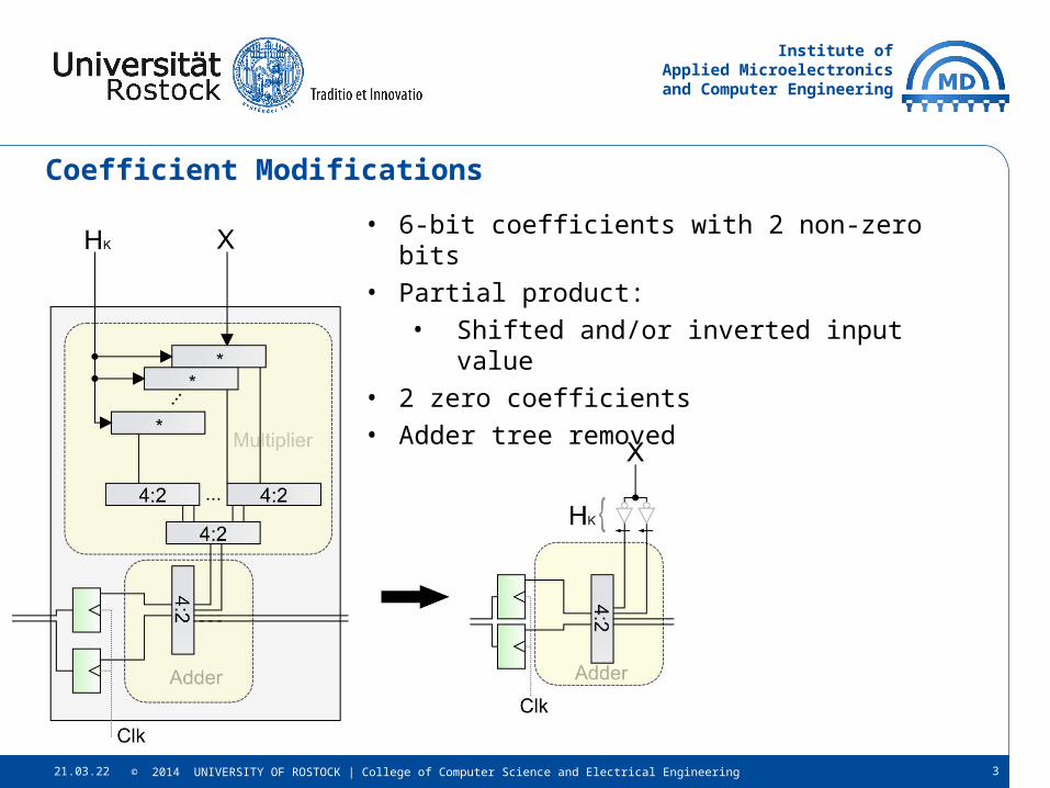
Coefficient Modifications
• 6-bit coefficients with 2 non-zero bits• Partial product:
• Shifted and/or inverted input value• 2 zero coefficients• Adder tree removed

Institute ofApplied Microelectronics
and Computer Engineering
18.04.23 4© 2014 UNIVERSITY OF ROSTOCK | College of Computer Science and Electrical Engineering
Carry-Select-Adder• Dedicated FPGA carry-logic
is only instanciated by
using „+“ or „-“ in VHDL• Last sum bit of a 4-bit RCA
is a function of 8 arguments
chain of two LUTs
• Adder:• Used in last stage• Operands:
24-bit sum vector
24-bit carry vector• 3 pipeline stages
Institute ofApplied Microelectronics
and Computer Engineering
18.04.23 5© 2014 UNIVERSITY OF ROSTOCK | College of Computer Science and Electrical Engineering
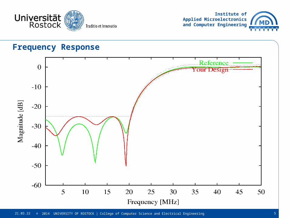
Frequency Response

Institute ofApplied Microelectronics
and Computer Engineering
18.04.23 6© 2014 UNIVERSITY OF ROSTOCK | College of Computer Science and Electrical Engineering
Metric (Backannotated)
Reference Phase 1 Phase 2
Frequency ~ 83 MHz ~ 200 MHz 709,723 MHz*
LUTs 1699 3095 437
D-FFs 288 905 753
# Stages 1 2 5
Static Power 242 mW 244 mW 244 mW
Dyn. Power 53 mW 253 mW 276 mW
Metric [MHz4/W] 1.61 * 108 3.22 * 109 4.88 * 1011
* Max. Total Setup Delay: 1.171 ns (~854 MHz)
Min. Clock Pulse Width: 1.408 ns (~710 MHz)
generated with Vivado default synthesis and implementation settings

Institute ofApplied Microelectronics
and Computer Engineering
18.04.23 7© 2014 UNIVERSITY OF ROSTOCK | College of Computer Science and Electrical Engineering
Observations / Conclusion
• CSDs are very efficient, less adder stages needed
• Reducing input data width• Leads to much smaller design• Mathematical incorrect result
• FPGA: think in LUTs <> ASIC: think in gatters• e. g. a 4:2 compressor is approx. as fast as a 3:2 adder

Institute ofApplied Microelectronics
and Computer Engineering
18.04.23 8© 2014 UNIVERSITY OF ROSTOCK | College of Computer Science and Electrical Engineering
Thank you for your attention!

Institute ofApplied Microelectronics
and Computer Engineering
18.04.23 9© 2014 UNIVERSITY OF ROSTOCK | College of Computer Science and Electrical Engineering
Overall Layout
• Same structure as last time (direct form II)• Accumulated sum of inverted input vectors
• Reduction of logic depth


