INSTANTANEOUS GAS WATER HEATER...
63
Page 1 from 63 6 720 814 719 SM FP_Australia 2014/12 EN INSTANTANEOUS GAS WATER HEATER GWI-N FAN PRESSURIZED GAS WATER HEATER FOR OUTDOOR INSTALLATION TRAINING AND SERVICE INFORMATION FOR AFTER SALES This document is restricted to exclusive use by the official service partners. Each country should adapt the manual and its contents to the available range.
Transcript of INSTANTANEOUS GAS WATER HEATER...

Page 1 from 63 6 720 814 719 SM FP_Australia 2014/12 EN
INSTANTANEOUS GAS WATER HEATER GWI-N
FAN PRESSURIZED GAS WATER HEATER FOR OUTDOOR INSTALLATION
TRAINING AND SERVICE INFORMATION FOR AFTER SALES
This document is restricted to exclusive use by the official service partners. Each country should adapt the manual and its contents to the available range.
Page 2 from 63
Contents
1. INTRODUCTION ........................................................................................... 3
2. APPLIANCE DESCRIPTION ......................................................................... 3
2.1 APPLIANCE DESIGNATION ...................................................................................................... 3 2.2 AVAILABLE ACCESSORIES ..................................................................................................... 3
3. INSTALLATION ............................................................................................. 5
3.1 APPLIANCE FIXATION ON THE WALL ........................................................................................ 5
3.2 WATER CONNECTIONS ........................................................................................................... 6 3.3 GAS CONNECTION ................................................................................................................. 6 3.4 APPLIANCE PERFORMANCE .................................................................................................... 7
4. COMPONENTS OVERVIEW ......................................................................... 8
4.1 CONTROL PANEL................................................................................................................... 8 4.2 HEAT CELL WITH BURNER PIPES ........................................................................................... 11
4.3 GAS MANIFOLD ................................................................................................................... 12 4.4 FAN ................................................................................................................................... 14 4.5 GAS VALVE ........................................................................................................................ 15
4.6 HEAT EXCHANGER .............................................................................................................. 16 4.7 WATER INLET ASSY ............................................................................................................ 17
4.8 WATER TEMPERATURE SENSORS ......................................................................................... 17
4.9 BOX TEMPERATURE SENSOR ............................................................................................... 17
4.10 WATER FLOW SENSOR ..................................................................................................... 18 4.11 IGNITION ELECTRODE ....................................................................................................... 19
4.12 IONIZATION ELECTRODE .................................................................................................... 21
5. WORKING PRINCIPLE / ELECTRIC MEASUREMENTS ............................ 21
6. SERVICE ..................................................................................................... 27
7. MAINTENANCE .......................................................................................... 39
8. TROUBLE SHOOTING ................................................................................ 44
Page 3 from 63
1. Introduction
This manual is a complement to the instruction/operation manual delivered with the appliance, with the main
important technical details that are relevant for the official service partners and trainers in the country. In any
case one of the documents replaces the use of the other.
2. Appliance description
This appliance is a fan pressurized gas water heater, which will replace the actual room sealed range of
appliances offering a wider range of modulation and installation advantages with both indoor and outdoor
models available.
2.1 Appliance Designation
The designation allows the identification of the main characteristics of the units, especially when report is needed
through call centre or after sales technicians.
T 4600 – Instantaneous gas water heater model
T 4600 S – fan pressurized operation
T 4600 S 12 / 15 / 18 – Output (flow rate at 25ºC rise)
T 4600 S 12 / 16 / 20 O – Flue less model for outdoor installation
T 4600 S 12 / 16 / 20 O 23/31 – Gas type (23 = natural gas / 31 = liquefied petroleum gas)
Segment Designation
Outdoor Installation
(temperature setting adjustable degree by degree)
T 4600 S 12 O 23
T 4600 S 12 O 31
T 4600 S 15 O 23
T 4600 S 15 O 31
T 4600 S 18 O 23
T 4600 S 18 O 31
Table 1 – Appliance identification
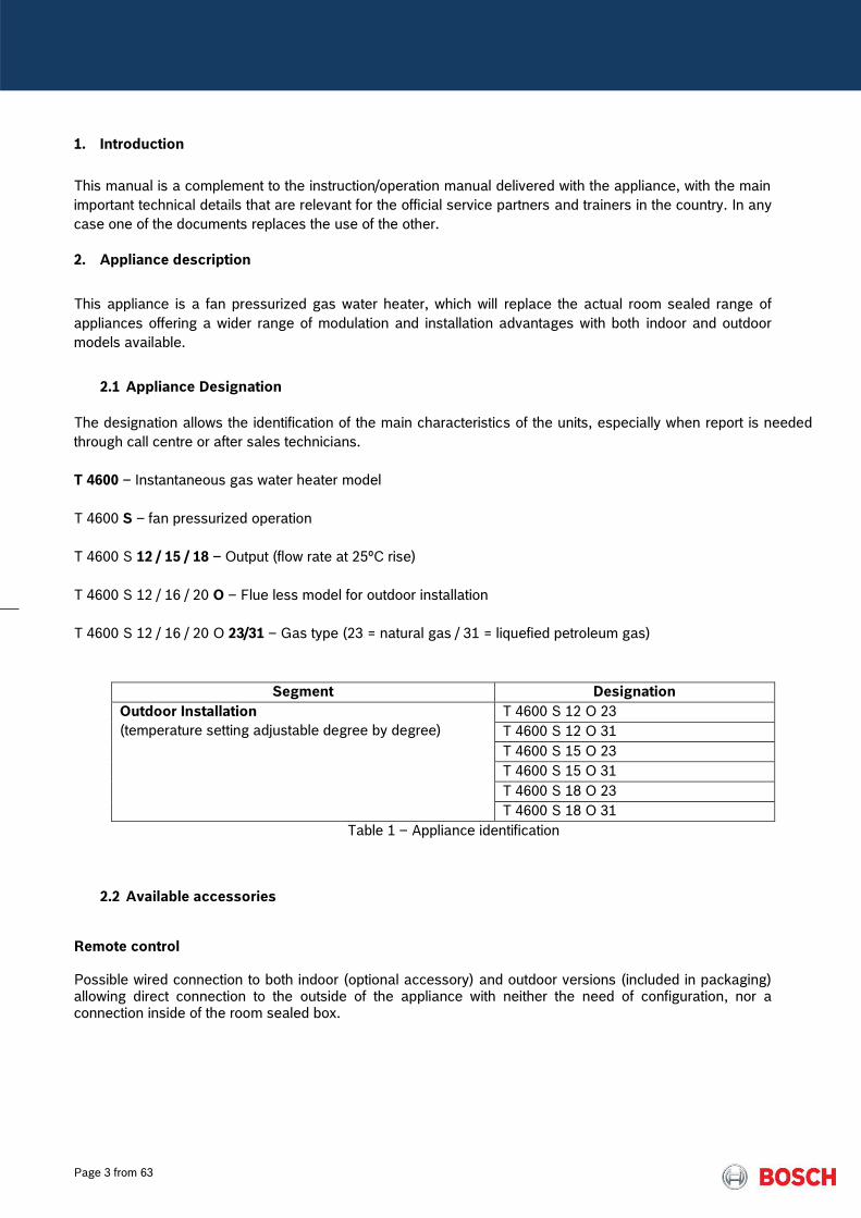
2.2 Available accessories Remote control Possible wired connection to both indoor (optional accessory) and outdoor versions (included in packaging) allowing direct connection to the outside of the appliance with neither the need of configuration, nor a connection inside of the room sealed box.
Page 4 from 63
Pict. 1 – Remote control connection to the appliance
Pict. 2 – Remote Control with cable, connectors
and instruction manual
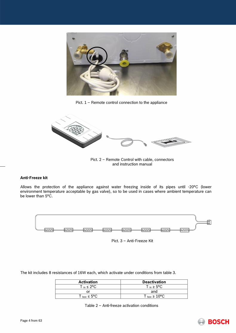
Anti-Freeze kit Allows the protection of the appliance against water freezing inside of its pipes until -20ºC (lower environment temperature acceptable by gas valve), so to be used in cases where ambient temperature can be lower than 5ºC.
Pict. 3 – Anti-Freeze Kit
The kit includes 8 resistances of 16W each, which activate under conditions from table 3.
Activation Deactivation
T in ≤ 2ºC T in ≥ 5ºC
or and
T box ≤ 5ºC T box ≥ 10ºC
Table 2 – Anti-freeze activation conditions

Page 5 from 63
3. Installation
The installation manual of each product must be checked and used by the installer in order to optimize and
leave the appliance in correct operation conditions.
Check lists for technicians/installers:
4.1 Appliance fixation on the wall
Requisite Confirmation
Appliance is levelled and in the vertical position?
Delivered accessories are used accordingly?
Appliance is supported exclusively by the wall fixation and not by hydraulic and/or gas connections?
Table 3 – Check List for Fixation
Pict.4 – Pre-installation distances
Page 6 from 63
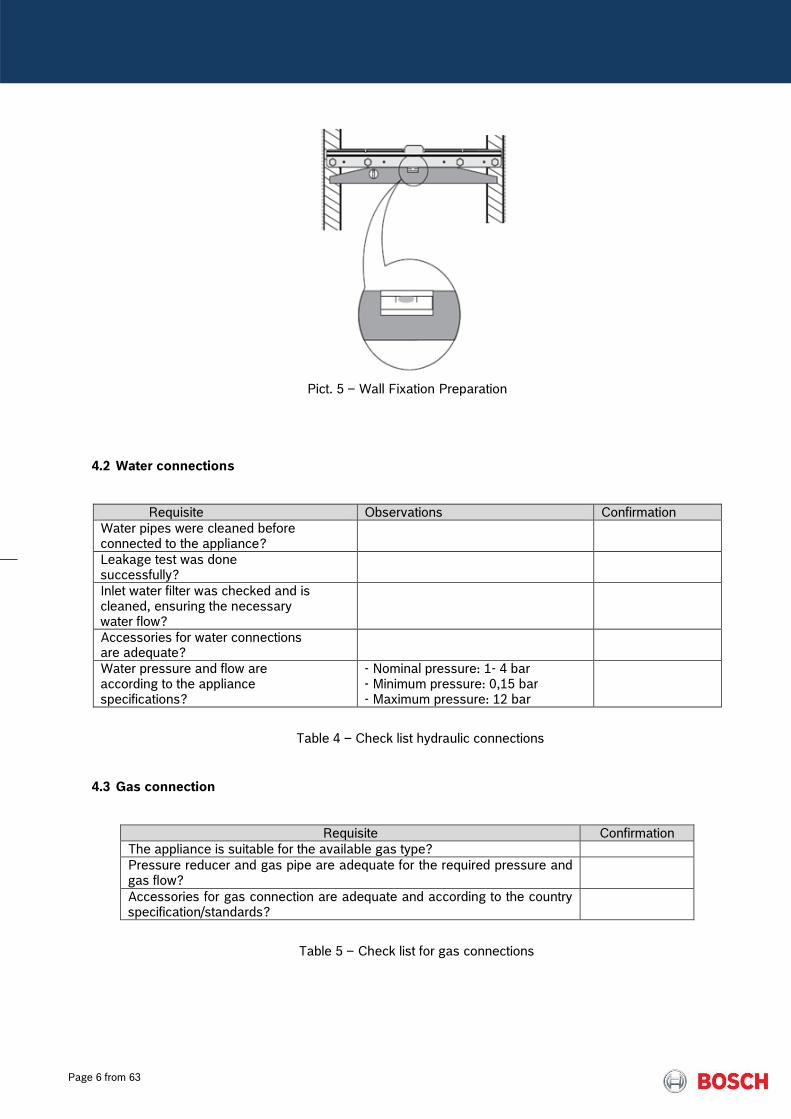
Pict. 5 – Wall Fixation Preparation
4.2 Water connections
Requisite Observations Confirmation
Water pipes were cleaned before connected to the appliance?
Leakage test was done successfully?
Inlet water filter was checked and is cleaned, ensuring the necessary water flow?
Accessories for water connections are adequate?
Water pressure and flow are according to the appliance specifications?
- Nominal pressure: 1- 4 bar - Minimum pressure: 0,15 bar - Maximum pressure: 12 bar
Table 4 – Check list hydraulic connections
4.3 Gas connection
Requisite Confirmation
The appliance is suitable for the available gas type?
Pressure reducer and gas pipe are adequate for the required pressure and gas flow?
Accessories for gas connection are adequate and according to the country specification/standards?
Table 5 – Check list for gas connections

Page 7 from 63
Pict. 6 – Manometer pipe connection to measure static/dynamic gas supply pressure
4.4 Appliance performance
Measure water flow and temperature increase to check temperature and instantaneous water flow, assuring
correct operation of the appliance.
Pict. 7 – Use of water flow meter and thermometer
gas manometer
Page 8 from 63
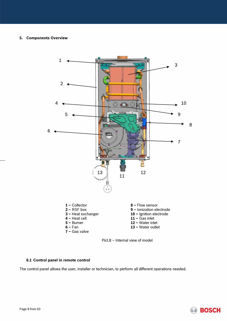
5. Components Overview
1 – Collector 2 – RSF box 3 – Heat exchanger 4 – Heat cell 5 – Burner 6 – Fan 7 – Gas valve
8 – Flow sensor 9 – Ionization electrode 10 – Ignition electrode 11 – Gas inlet 12 – Water inlet 13 – Water outlet
Pict.8 – Internal view of model
6.1 Control panel in remote control The control panel allows the user, installer or technician, to perform all different operations needed.
1 3
2
4
6
10
9
8
7
5
11 12 13

Page 9 from 63
Pict.9 – wired remote control
On / Off button
The main switch is assembled on
the PCB and disconnects phase-L
from neutral-N.
No voltage at components if the
main switch is in OFF-position
Note: Errors reset function when
pressed for more than 3 seconds
Program Button
Used to enter in different services:
- Enter in service mode
- Scroll in the service mode menu
- Save value or adjust set values
- Save a temperature set (user)
Selection button
Used to select temperature values,
adjustments and navigation on
parameters inside the visualisation
mode.
Table 6 – Control Panel Buttons

Page 10 from 63
Symbol Description Observation
Temperature Unit:
ºC – default value
ºF – alternative value
Selection can be done by changing
default value on service mode (P6)
Power bar indicator:
Indication of the current operation
power
Indicative Value (in %)
Flame indication:
Indication of flame in the burner
Symbol displayed when ionization is
detected - flame presence
Warning symbol:
Combined with an error indication
/ warning code indicates a faulty
performance
Tap symbol:
Indication of not enough power to
reach set point
In case symbol is displayed,
decrease (-) or increase (+) flow
accordingly
Solar application:
Indication that the automatic solar
function is activated, meaning that
the appliance is receiving pre-
heated inlet water, with no need
for burner to start
The symbol is displayed and burner
is shutdown when T in is under
following conditions:
T in ≥ T set – 1K
The symbol is deactivated and
burner restarted when:
T out < 60ºC (if T set ≤ 50ºC)
T out < T set + 10ºC (if T set > 50ºC)
Fan operation:
Indication that the fan is in
operation
Table 7 – Display Symbols

Page 11 from 63
6.2 Heat cell with burner pipes The heat cell includes the flame visualization window, ignition electrode, ionization electrode and the burner pipes.
Inlet: Primary air from the fan and gas from the gas manifold. Outlet: Hot combustion gases to the heat exchanger
Pict.10 – Heat cell detail with ignition / ionization electrodes
Pict.11 – Burner blade Primary air plate The primary air plate is assembled between the heat cell and the gas manifold in order to ensure the correct mixture of air and gas according to the specific appliance model.
Appliance Stamp
12l/min 12 L
15l/min 15 L
18l/min 18 L
Table 8 – Identification of primary air plates
The plate has indexation pins that ensure the correct assembly on the heat cell and the type gas mark orientation to the front.

Page 12 from 63
Pict. 12 – Primary air plate
6.3 Gas manifold The gas manifold is a gas distribution pipe with integrated drilled injectors and two pressure measuring points:
- gas valve pressure = Pburner - air fan pressure = Pbox
The manifold cover allows the gas supply to the burner over 2 different segments, in order to assure a wide modulation range according to the capacity of the appliance. The gas manifold for GWH 12 models have in total 9 injectors with following distribution:
- NG Ø 1.7 - LPG Ø 1.3
Pict. 13 – Gas manifold for 12l/min appliance with 9 injectors
Burner segment 1
Burner segment 2
GWH 12
GWH 18
Injectors
GWH 15
Page 13 from 63
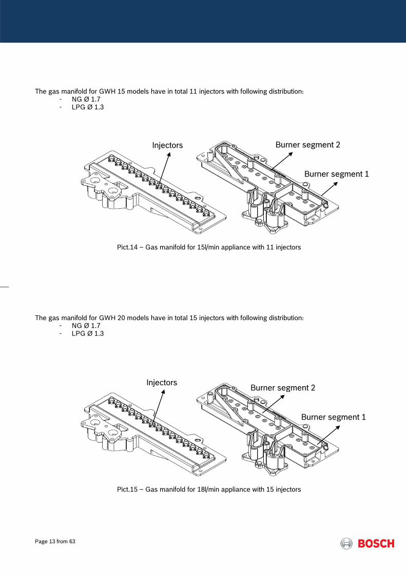
The gas manifold for GWH 15 models have in total 11 injectors with following distribution:
- NG Ø 1.7 - LPG Ø 1.3
Pict.14 – Gas manifold for 15l/min appliance with 11 injectors
The gas manifold for GWH 20 models have in total 15 injectors with following distribution:
- NG Ø 1.7 - LPG Ø 1.3
Pict.15 – Gas manifold for 18l/min appliance with 15 injectors
Burner segment 1
Burner segment 2
Burner segment 1
Burner segment 2
Injectors
Injectors
Page 14 from 63
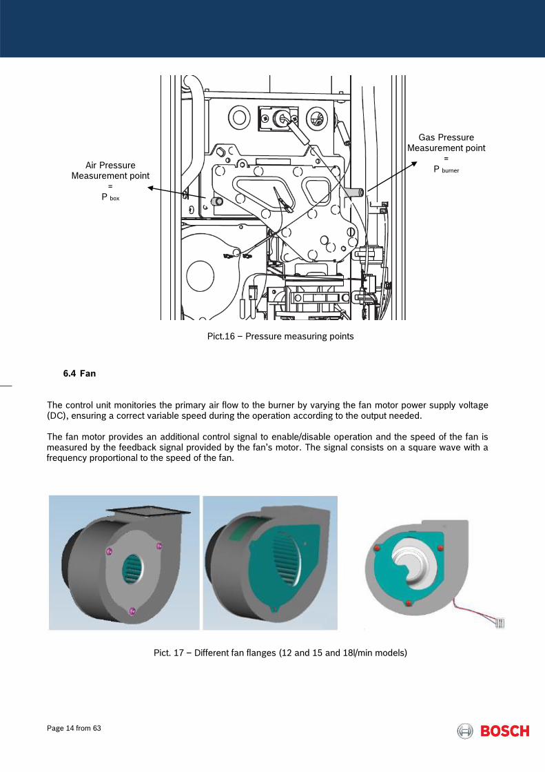
Pict.16 – Pressure measuring points
6.4 Fan The control unit monitories the primary air flow to the burner by varying the fan motor power supply voltage (DC), ensuring a correct variable speed during the operation according to the output needed. The fan motor provides an additional control signal to enable/disable operation and the speed of the fan is measured by the feedback signal provided by the fan’s motor. The signal consists on a square wave with a frequency proportional to the speed of the fan.
Pict. 17 – Different fan flanges (12 and 15 and 18l/min models)
Gas Pressure Measurement point
= P burner
Air Pressure Measurement point
= P box
Page 15 from 63
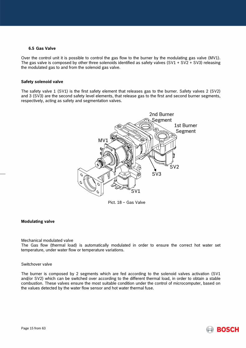
6.5 Gas Valve Over the control unit it is possible to control the gas flow to the burner by the modulating gas valve (MV1). The gas valve is composed by other three solenoids identified as safety valves (SV1 + SV2 + SV3) releasing the modulated gas to and from the solenoid gas valve. Safety solenoid valve The safety valve 1 (SV1) is the first safety element that releases gas to the burner. Safety valves 2 (SV2) and 3 (SV3) are the second safety level elements, that release gas to the first and second burner segments, respectively, acting as safety and segmentation valves.
Pict. 18 – Gas Valve
Modulating valve Mechanical modulated valve The Gas flow (thermal load) is automatically modulated in order to ensure the correct hot water set temperature, under water flow or temperature variations. Switchover valve The burner is composed by 2 segments which are fed according to the solenoid valves activation (SV1 and/or SV2) which can be switched over according to the different thermal load, in order to obtain a stable combustion. These valves ensure the most suitable condition under the control of microcomputer, based on the values detected by the water flow sensor and hot water thermal fuse.
SV1
SV3
SV2
MV1
2nd Burner Segment
1st Burner Segment
Page 16 from 63
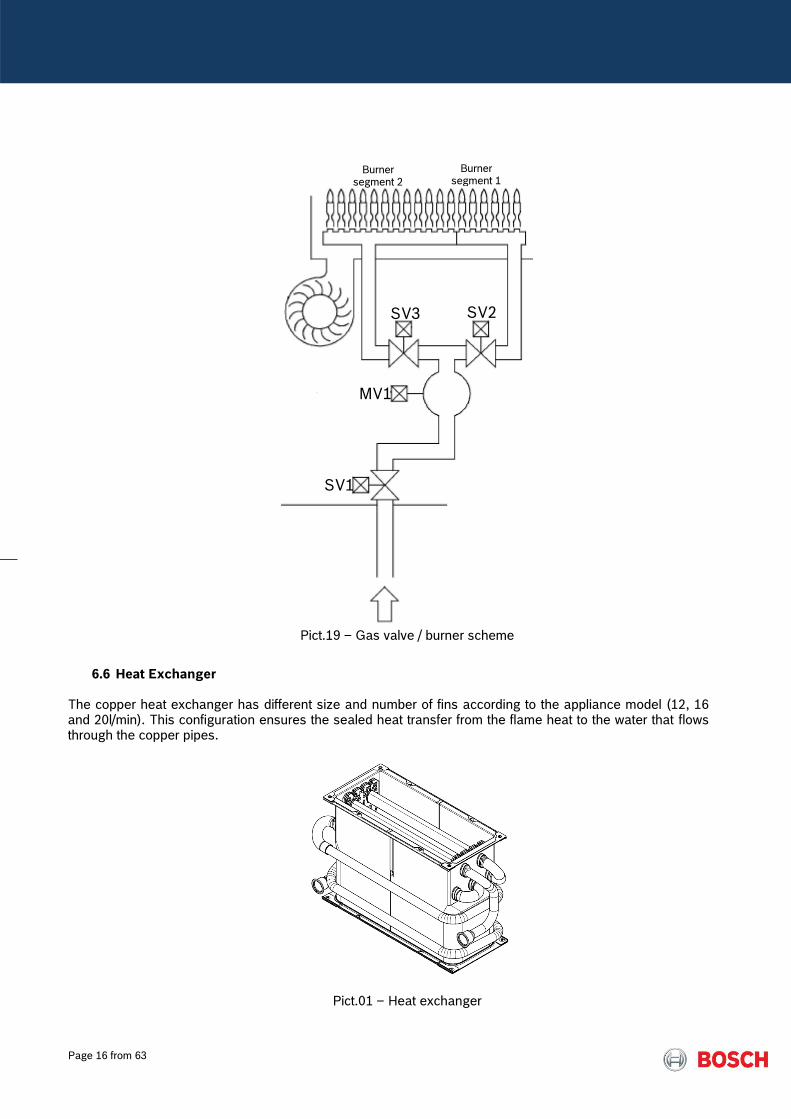
Pict.19 – Gas valve / burner scheme
6.6 Heat Exchanger The copper heat exchanger has different size and number of fins according to the appliance model (12, 16 and 20l/min). This configuration ensures the sealed heat transfer from the flame heat to the water that flows through the copper pipes.
Pict.01 – Heat exchanger
SV2
SV1
SV3
MV1
Burner segment 1
Burner segment 2

Page 17 from 63
6.7 Water Inlet Assy
The inlet water valve contains the water connection of 1/2” that integrates also the filter.
Pict.21 – Inlet Water Valve
6.8 Water temperature sensors
The outlet and inlet water temperature is measured by a 10kΩ NTC (See table 15). Both NTC are equal, but connected to different cable colors (blue wires to inlet water / red wires to outlet water).
Pict.22 – Temperature sensor
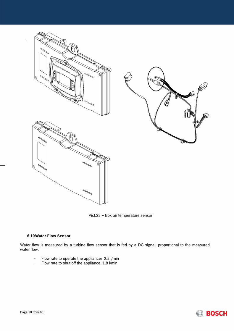
6.9 Box Temperature sensor The Box air temperature is measured by a 220kΩ NTC (See table 14) and is assembled on the control unit back panel, in order to monitor the temperature inside of the room sealed box.
Page 18 from 63
Pict.23 – Box air temperature sensor
6.10 Water Flow Sensor Water flow is measured by a turbine flow sensor that is fed by a DC signal, proportional to the measured water flow.
- Flow rate to operate the appliance: 2.2 l/min - Flow rate to shut off the appliance: 1.8 l/min
Page 19 from 63
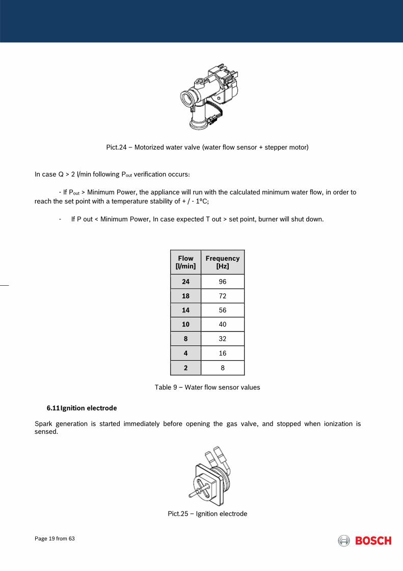
Pict.24 – Motorized water valve (water flow sensor + stepper motor)
In case Q > 2 l/min following Pout verification occurs:
- If Pout > Minimum Power, the appliance will run with the calculated minimum water flow, in order to
reach the set point with a temperature stability of + / - 1ºC;
- If P out < Minimum Power, In case expected T out > set point, burner will shut down.
Flow [l/min]
Frequency [Hz]
24 96
18 72
14 56
10 40
8 32
4 16
2 8
Table 9 – Water flow sensor values
6.11 Ignition electrode Spark generation is started immediately before opening the gas valve, and stopped when ionization is sensed.
Pict.25 – Ignition electrode

Page 20 from 63
In order to prevent harder ignition processes and be sure of conditions of gas supply and burner stability,
following situation is verified during the so called safety time period.
In each of the attempts, the system monitors the ionisation signal; this signal drives the start of normal
operation, however and, in case the ionization signal is not detected during the ignition sequence, the failure
indication EA will be displayed. In this case a non-volatile lock-out is activated, and only a manual reset can
lead the system back to normal operation. If the ionisation signal is interrupted during normal operation, this
ignition sequence is re-started.
Fan Ignition spark
1st & 2nd Ignition Sequence Safety Time = 29 sec
1st Attempt (5 sec)
Purge Period (3 sec)
2nd Attempt (5 sec)
Purge Period (3 sec)
3rd Attempt (5 sec)
Pos Purge (8 sec)
+
+
+
3rd Ignition Sequence Safety Time of 21 sec + 3 min (ready start state)
1st Attempt (5 sec)
Purge Period (3 sec)
2nd Attempt (5 sec)
Purge Period (3 sec)
3rd Attempt (5 sec)
Pos Purge (3 min)
+
+
+
Page 21 from 63
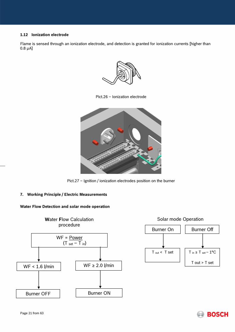
1.12 Ionization electrode Flame is sensed through an ionization electrode, and detection is granted for ionization currents [higher than 0.8 µA]
Pict.26 – Ionization electrode
Pict.27 – Ignition / ionization electrodes position on the burner
7. Working Principle / Electric Measurements
Water Flow Detection and solar mode operation
Water Flow Calculation procedure
WF = Power (T set – T in)
WF ≥ 2.0 l/min
Burner ON
WF < 1.6 l/min
Burner OFF
Burner On
Solar mode Operation
Burner Off
T in ≥ T set – 1ºC
T out > T set
T out < T set
Page 22 from 63
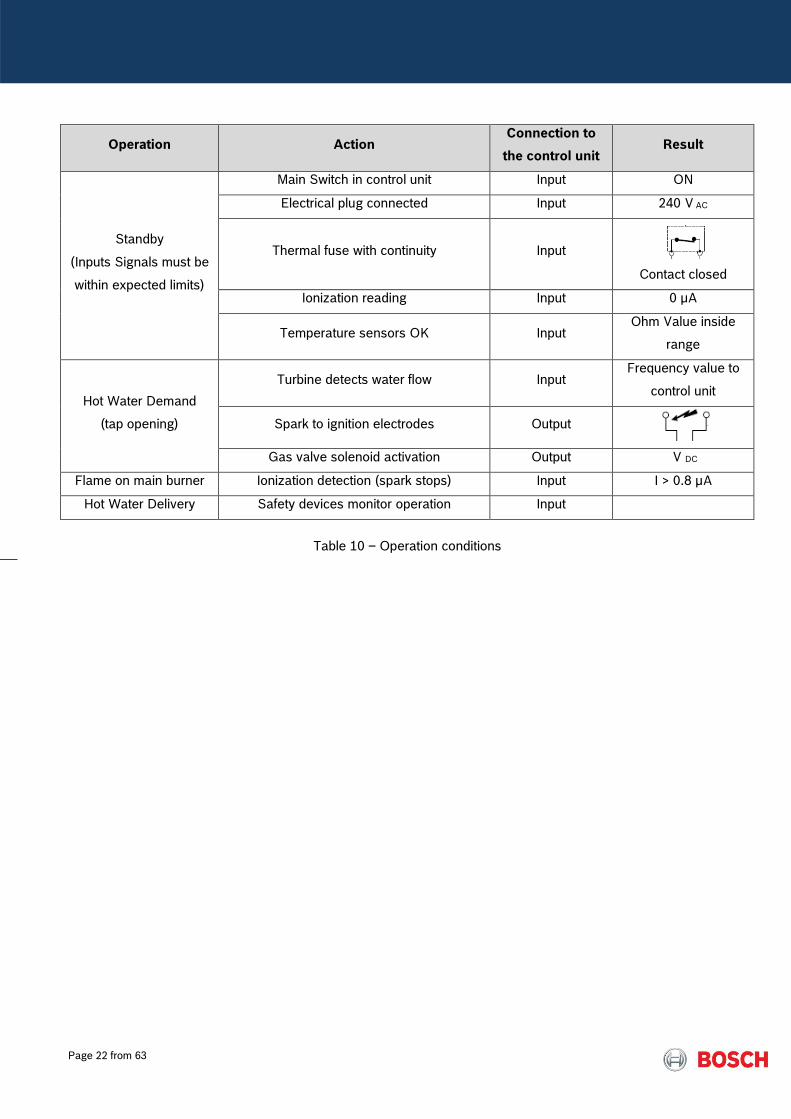
Operation Action Connection to
the control unit Result
Standby
(Inputs Signals must be
within expected limits)
Main Switch in control unit Input ON
Electrical plug connected Input 240 V AC
Thermal fuse with continuity Input
Contact closed
Ionization reading Input 0 µA
Temperature sensors OK Input Ohm Value inside
range
Hot Water Demand
(tap opening)
Turbine detects water flow Input Frequency value to
control unit
Spark to ignition electrodes Output
Gas valve solenoid activation Output V DC
Flame on main burner Ionization detection (spark stops) Input I > 0.8 µA
Hot Water Delivery Safety devices monitor operation Input
Table 10 – Operation conditions
Page 23 from 63
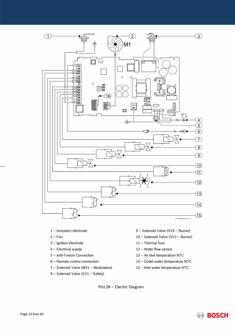
1 – Ionization electrode
2 – Fan
3 – Ignition electrode
4 – Electrical supply
5 – Anti-Freeze Connection
6 – Remote control connection
7 – Solenoid Valve (MV1 – Modulation)
8 – Solenoid Valve (SV1 – Safety)
9 – Solenoid Valve (SV3 – Burner)
10 – Solenoid Valve (SV2 – Burner)
11 – Thermal fuse
12 – Water flow sensor
13 – Air Box temperature NTC
14 – Outlet water temperature NTC
15 – Inlet water temperature NTC
Pict.28 – Electric Diagram
Page 24 from 63
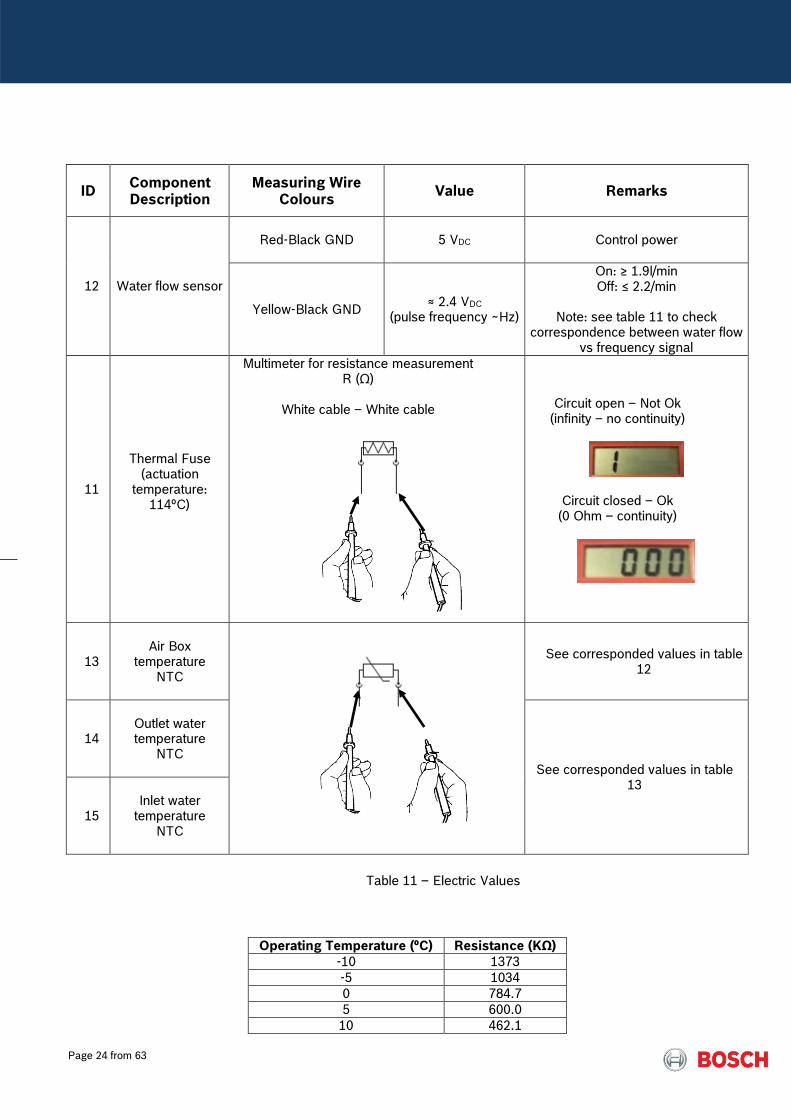
ID Component Description
Measuring Wire Colours
Value Remarks
12 Water flow sensor
Red-Black GND
5 VDC Control power
Yellow-Black GND ≈ 2.4 VDC
(pulse frequency ~Hz)
On: ≥ 1.9l/min Off: ≤ 2.2/min
Note: see table 11 to check
correspondence between water flow vs frequency signal
11
Thermal Fuse (actuation
temperature: 114ºC)
Multimeter for resistance measurement R (Ω)
White cable – White cable
Circuit open – Not Ok (infinity – no continuity)
Circuit closed – Ok (0 Ohm – continuity)
13
Air Box
temperature NTC
See corresponded values in table 12
14
Outlet water temperature
NTC See corresponded values in table
13
15
Inlet water
temperature NTC
Table 11 – Electric Values
Operating Temperature (ºC) Resistance (KΩ)
-10 1373
-5 1034
0 784.7
5 600.0
10 462.1

Page 25 from 63
15 358.4
20 279.9
25 220.0
30 174.0
35 138.5
40 110.9
45 89.24
50 72.24
55 58.78
60 48.08
65 39.51
70 32.63
75 27.07
80 22.56
85 18.88
90 15.87
95 13.39
100 11.34
105 9.642
110 8.228
Table 12 – NTC resistance values for Air Box NTC
Operating Temperature (ºC)
R min (KΩ)
R nominal (KΩ)
R max (KΩ)
0 30.34 30.40 36.47
5 23.674 25.902 28.129
10 18.617 20.247 21.878
15 14.749 15.950 17.151
20 11.768 12.657 13.547
25 9.454 10.115 10.777
30 7.644 8.138 8.632
35 6.218 6.589 6.959
40 5.089 5.367 5.646
45 4.188 4.398 4.608
50 3.466 3.624 3.782
55 2.883 3.002 3.122
60 2.410 2.500 2.590
65 2.009 2.092 2.175
70 1.683 1.759 1.835
75 1.416 1.486 1.555
80 1.197 1.260 1.323
85 1.016 1.074 1.131
90 0.866 0.918 0.970
95 0.741 0.788 0.836
100 0.637 0.680 0.722
105 0.549 0.588 0.627
110 0.475 0.510 0.545
Table 13 – NTC resistance values for water temperature NTC’s
Page 26 from 63
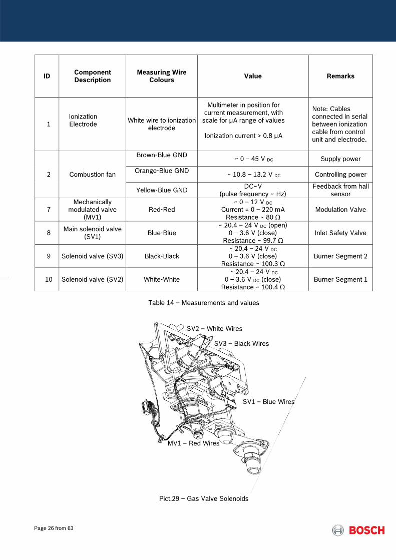
ID Component Description
Measuring Wire Colours
Value Remarks
1 Ionization Electrode
White wire to ionization electrode
Multimeter in position for current measurement, with
scale for µA range of values
Ionization current > 0.8 µA
Note: Cables connected in serial between ionization cable from control unit and electrode.
2 Combustion fan
Brown-Blue GND
~ 0 – 45 V DC Supply power
Orange-Blue GND
~ 10.8 – 13.2 V DC Controlling power
Yellow-Blue GND DC~V
(pulse frequency ~ Hz) Feedback from hall
sensor
7 Mechanically
modulated valve (MV1)
Red-Red ~ 0 – 12 V DC
Current = 0 – 220 mA Resistance ~ 80 Ω
Modulation Valve
8 Main solenoid valve
(SV1) Blue-Blue
~ 20.4 – 24 V DC (open) 0 – 3.6 V (close)
Resistance ~ 99.7 Ω Inlet Safety Valve
9 Solenoid valve (SV3) Black-Black ~ 20.4 – 24 V DC 0 – 3.6 V (close)
Resistance ~ 100.3 Ω Burner Segment 2
10 Solenoid valve (SV2) White-White ~ 20.4 – 24 V DC
0 – 3.6 V DC (close) Resistance ~ 100.4 Ω
Burner Segment 1
Table 14 – Measurements and values
Pict.29 – Gas Valve Solenoids
SV2 – White Wires
SV3 – Black Wires
SV1 – Blue Wires
MV1 – Red Wires
Page 27 from 63
In order to ensure a correct start up of the appliance and a correct function after any intervention on the
appliance, the installation manual must be read and instructions and main functions must be explained to the
end user.
Table 16 indicates the method and values for testing the main components function and, consequently,
ensure a correct and safe operation of the appliance.
8. Service
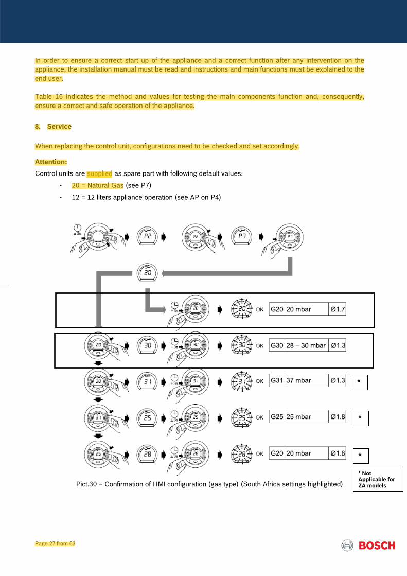
When replacing the control unit, configurations need to be checked and set accordingly.
Attention:
Control units are supplied as spare part with following default values:
- 20 = Natural Gas (see P7)
- 12 = 12 liters appliance operation (see AP on P4)
Pict.30 – Confirmation of HMI configuration (gas type) (South Africa settings highlighted)
* Not Applicable for ZA models
*
*
*
Alister
Highlight
Alister
Highlight
Alister
Highlight
Alister
Highlight
Page 28 from 63
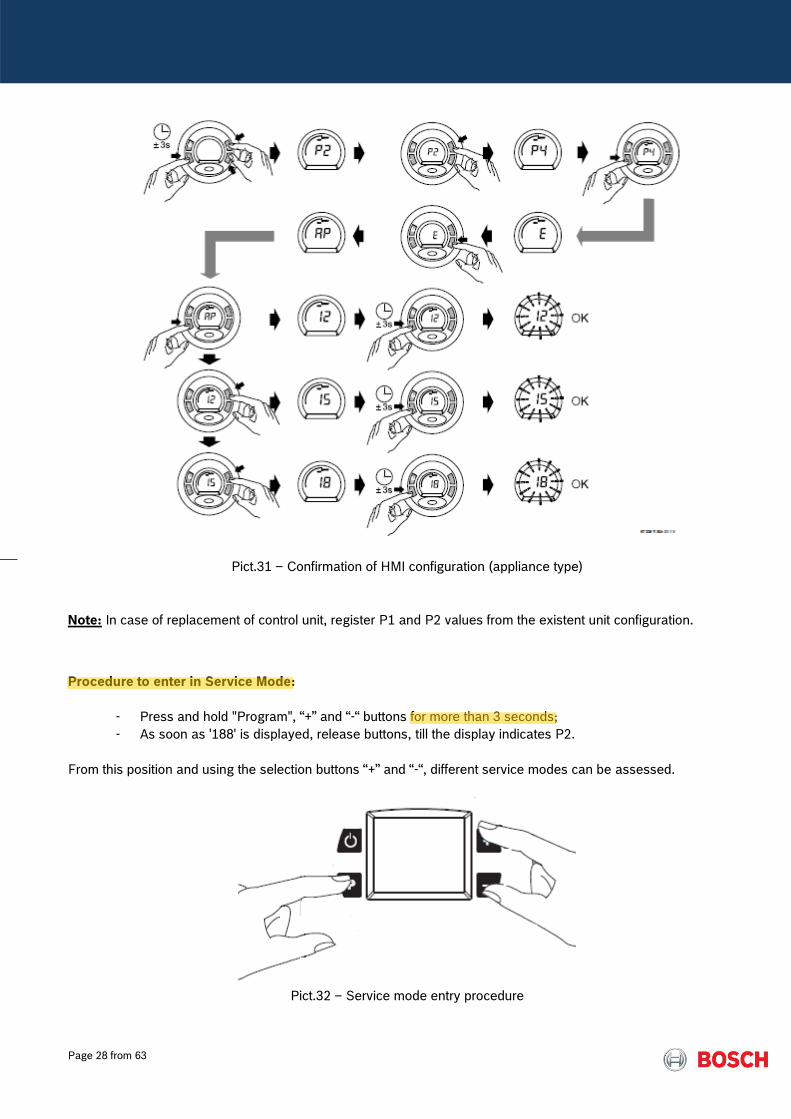
Pict.31 – Confirmation of HMI configuration (appliance type)
Note: In case of replacement of control unit, register P1 and P2 values from the existent unit configuration. Procedure to enter in Service Mode:
- Press and hold "Program", “+” and “-“ buttons for more than 3 seconds;
- As soon as '188' is displayed, release buttons, till the display indicates P2.
From this position and using the selection buttons “+” and “-“, different service modes can be assessed.
Pict.32 – Service mode entry procedure
Alister
Highlight
Alister
Highlight
Page 29 from 63
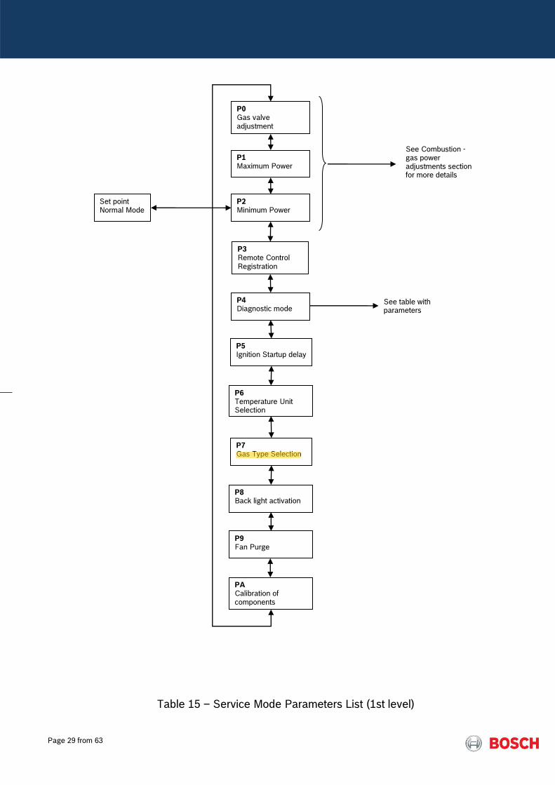
Table 15 – Service Mode Parameters List (1st level)
P1 Maximum Power
P2 Minimum Power
P3 Remote Control Registration
P4 Diagnostic mode
P5 Ignition Startup delay
P6 Temperature Unit Selection
P7 Gas Type Selection
Set point Normal Mode
P0 Gas valve adjustment
P8 Back light activation
See Combustion - gas power adjustments section for more details
P9 Fan Purge
PA Calibration of components
See table with parameters
Alister
Highlight
Page 30 from 63
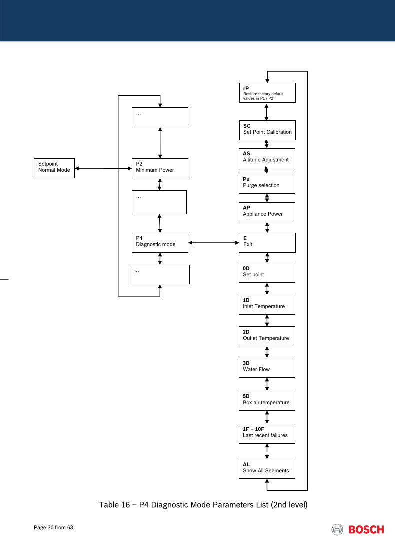
Table 16 – P4 Diagnostic Mode Parameters List (2nd level)
…
P2 Minimum Power
…
P4 Diagnostic mode
…
E Exit
0D Set point
1D Inlet Temperature
2D Outlet Temperature
3D Water Flow
5D Box air temperature
1F – 10F Last recent failures
AL Show All Segments
rP Restore factory default values in P1 / P2
AP Appliance Power
Setpoint Normal Mode
AS Altitude Adjustment
SC Set Point Calibration
Pu Purge selection

Page 31 from 63
Combustion – Gas Power Adjustment Parameters
The adjustment of the appliance for minimum / maximum power operation can be needed under following
conditions:
- Gas Conversion (see correspondent manual);
- Gas valve replacement;
- Start up of unit when need to operate with Propane (LPG models are adjusted on factory for Butane).
Following image indicates the 2 measurement points to be used:
Pict.33 – P0 / P1 / P2 adjustment measurement points
Pict.34 – Gas Manometer Connection
Gas Pressure Measurement Point Measurable values:
- P burner - P0 - P1 – L1 - P2 – L2
Fan Pressure Measurement Point
Measurable values:
- P box - P1 – A1 - P2 – A2

Page 32 from 63
Technician Level Comments
The value measured when in
P0 should be 1.2 mbar
Range of value in control unit is from 0
to 40
Spare part default setting is 20
Table 17 – P0
The P1 mode can be accessed in the service mode, depending on the adjustment and/or
confirmation need. Check parameters according gas and model type and check results
according to the manual – ensure constant result (P burner – P box = P L1 – P A1)
To keep the appliance in P1 (maximum power adjustment), is important to assure a minimum
water flow, otherwise the appliance will jump automatically to P2 (minimum power).
GWH 12: Flow > 4 l/min
GWH 16: Flow > 6 l/min
GWH 20: Flow > 6 l/min
Table 18 – Minimum water flow needed to keep P1
Maximum Power adjustment
Technician Level Comments
Maximum power burner
adjustment after repairs /
maintenance / gas
conversions
P1 contains the fan speed setting (A1)
and gas power (L1) at maximum power
(depends on gas type / model)
When P1 is visible, press “P” and enter in the 2nd level accessing “E”
for enter and/or exit P1
Maximum Input Power Not Used (by default will display 20)

Page 33 from 63
Adjustment of air flow without
change gas conditions
Range from 0 to 40
Spare part default setting is 20
Adjustment of gas flow
without change air conditions
Range from 0 to 40
Spare part default setting is 20
Table 19 – P1 sub menus
Values in P1 mode are settled according to the appliance selection and gas type from
factory. To check default value or to change parameter, press “Program” button when
inside of P1.
Appliance Natural Gas Butane
P1
ΔP (kPa)
GWH 12 0,48 - 0,56 0,42 - 0,54
GWH 15 0,44 - 0,56 0,44 - 0,56
GWH 18 0,40 - 0,52 0,38 - 0,50
P2
ΔP (kPa)
GWH 12 0,04 - 0,08 0,05 - 0,09
GWH 15 0,04 - 0,08 0,05 - 0,09
GWH 18 0,08 - 0,09 0,04 - 0,08
Table 20 – Values measured on gas manometer
The P2 mode can be accessed in the service mode, depending on adjustment and/or
confirmation need. Check parameters according gas and model type and check results
according to the manual – ensure constant result (Pburner – Pbox = PL2 – PA2)
Minimum Power adjustment
(Minimum gas and water flow)
Technician Level Comments
Minimum power burner
adjustment after repairs /
maintenance / gas
conversions
P2 contains the fan speed setting (A2)
and gas power (L2) at maximum power
(depends on gas type / model)
(depends on gas type / model)

Page 34 from 63
When P2 is visible, press “P” and enter in the 2nd level accessing “E”
for enter and/or exit P1
Minimum Input Power Not Used (by default will display 20)
Adjustment of air flow without
change gas conditions
Range from 0 to 40
Spare part default setting is 20
Adjustment of gas flow
without change air conditions
Range from 0 to 40
Spare part default setting is 20
Table 21 – P2 sub menus
Remote control registration Installer Level Technician Level Comments
Not used
Table 22 – P3
The access to the data visualization mode, is made by entering first in the “service mode”
and then, scrolling to the parameter “P4” of the adjustment mode.
Diagnostic mode and visualization mode
Installer Level Technician Level Comments
This mode helps the
installer in the startup
to check parameters
such as water flow
through the appliance
and inlet / outlet
temperatures
This mode helps the
technician to find some
information useful to
adjust and to check
functionality of the
appliance.
Main recommendation is
to perform always a check
on the last 10 failures in
memory in order to
analyze eventual
problems in installation
that might need to be
corrected
Table 23 – P4

Page 35 from 63
By pressing the “P” button while the display shows “P4”, the LCD will enter into
visualization mode and will show “E”, meaning “Exit” from the visualization mode. By
pressing “P” button again, the LCD will show “P4”, i.e. the visualization mode has been
exited.
After entering into data visualization mode (showing “E”) and then pressing “+” or “-”
button, the parameter and failure visualization fields can be selected as shown in table 5.
Sequence of
Parameters in P4 Comment Value / Unit
Entry / Exit of visualization mode
Possible change of set point
without leave service mode and
perform any needed control
ºC or ºF
(depends on P6 setting)
Temperature indication
Inlet water temperature
Temperature read by inlet sensor
ºC or ºF
Temperature indication
Hot water temperature
Temperature read by outlet sensor
ºC or ºF
Water flow indication
l/min ( ±0.5l/min )
Indicates water flow measured by the
turbine (l/min)
Not existing
Temperature of air in room sealed
box
Temperature read by outlet sensor
ºC or ºF
until
Last 10 Failures for diagnostic
purposes
Failure 1 is last failure occurred
Failure 2 occurred before Failure1
Failure 3 occurred before Failure2
Failure 4 occurred before Failure3
Failure 5 occurred before Failure4
Failure 6 occurred before Failure5
Failure 7 occurred before Failure6
Failure 8 occurred before Failure7
Failure 9 occurred before Failure8
Failure 10 occurred before Failure9
Page 36 from 63
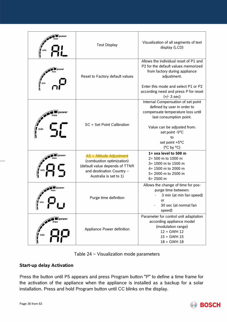
Test Display Visualization of all segments of text
display (LCD)
Reset to Factory default values
Allows the individual reset of P1 and
P2 for the default values memorized
from factory during appliance
adjustment.
Enter this mode and select P1 or P2
according need and press P for reset
(+/- 3 sec)
SC = Set Point Calibration
Internal Compensation of set point
defined by user in order to
compensate temperature loss until
last consumption point.
Value can be adjusted from:
set point -5ºC
to
set point +5ºC
(ºC by ºC)
AS = Altitude Adjustment
(combustion optimization)
(default value depends of TTNR
and destination Country –
Australia is set to 1)
1= sea level to 500 m
2= 500 m to 1000 m
3= 1000 m to 1500 m
4= 1500 m to 2000 m
5= 2000 m to 2500 m
6> 2500 m
Purge time definition
Allows the change of time for pos-
purge time between:
- 3 min (at min fan speed)
or
- 30 sec (at normal fan
speed)
Appliance Power definition
Parameter for control unit adaptation
according appliance model
(modulation range)
12 = GWH 12
15 = GWH 15
18 = GWH 18
Table 24 – Visualization mode parameters
Start-up delay Activation
Press the button until P5 appears and press Program button “P” to define a time frame for
the activation of the appliance when the appliance is installed as a backup for a solar
installation. Press and hold Program button until CC blinks on the display.
Alister
Highlight

Page 37 from 63
Start up delay Default Value Comments
______
(Note: from 0 to 60 sec)
The value defined here is defined in seconds and
will create a delay in the startup sequence since
flow rate is detected in order to allow pre-heated
water to reach appliance without unnecessary
burner activation when water is hot.
Table 25 – P5
Temperature Unit selection
To change the temperature unit, enter first into the service mode and then scroll to the
parameter “P6”. By pressing the “P” button while the display shows “P6”, the LCD will
enter into temperature selection unit mode and show “C” which indicates “Celsius degree”.
Pushing “+” or “-” button, the LCD will show “F” which indicates “Fahrenheit degree”.
Temperature unit selection Default Value Possible
Selection Comments
ºC ºF
To set one of these units it is
necessary to store the value.
For that, press program button
until the desired option flashes
on the display
Table 26 – P6
To change the gas type, enter first into the service mode and then scroll to the parameter
“P7”. This parameter allows the control of the modulation range according to the gas type.
In order to ensure a proper operation of the appliance, this parameter must be checked
when the control unit is replaced.
Appliance Type selection Settings: Comments
20 – Natural Gas G20
(with injectors of 1.7)
30 – Butane G30
31 – Propane G31
25 – Natural Gas G25
28 – natural Gas G20
(with injectors of 1.8)
NG models will have
from factory 20
LPG models will have
from factory 31
Note: spare part pre-set value
is 20
Table 27 – P7
Alister
Highlight
Alister
Highlight
Alister
Highlight
Alister
Highlight
Alister
Highlight
Alister
Highlight
Page 38 from 63
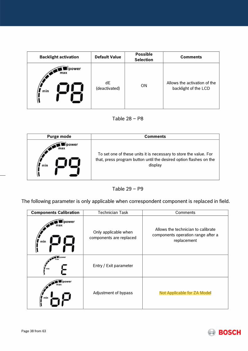
Backlight activation Default Value Possible
Selection Comments
dE
(deactivated) ON
Allows the activation of the
backlight of the LCD
Table 28 – P8
Purge mode Comments
To set one of these units it is necessary to store the value. For
that, press program button until the desired option flashes on the
display
Table 29 – P9
The following parameter is only applicable when correspondent component is replaced in field.
Components Calibration Technician Task Comments
Only applicable when
components are replaced
Allows the technician to calibrate
components operation range after a
replacement
Entry / Exit parameter
Adjustment of bypass Not Applicable for ZA Model
Alister
Highlight

Page 39 from 63
Adjustment of motorized
water valve (stepper motor) Not applicable for ZA market
Adjustment of water flow
sensor
Open hot water to start appliance and press
P checking the water flow
(l/s x 10).
Appliance will shut off while calibration is
being done until inlet and outlet NTC
measure same temperature and water flow
start blinking.
Press P to finish.
Table 30 – PA
9. Maintenance
To ensure continued efficient operation of the appliance, it is recommended that it is checked and serviced as necessary at regular intervals. The frequency of servicing will depend on the particular installation conditions and use profile, but in general, once a year should be adequate. Any intervention / service work in the appliance must be carried out by a competent person such as registered and competent technician. Before any service operation, turn off the gas supply at the main gas service cock upstream. Carry out the service operation as described in the manual. The service partners have all necessary accessories and tools for the interventions.
Alister
Highlight
Alister
Highlight
Alister
Highlight
Alister
Highlight
Page 40 from 63
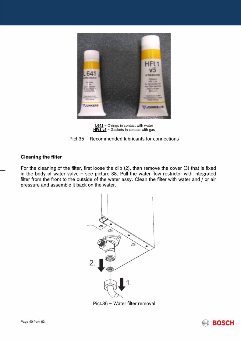
L641 – O’rings in contact with water HFt1 v5 – Gaskets in contact with gas
Pict.35 – Recommended lubricants for connections
Cleaning the filter For the cleaning of the filter, first loose the clip (2), than remove the cover (3) that is fixed in the body of water valve – see picture 38. Pull the water flow restrictor with integrated filter from the front to the outside of the water assy. Clean the filter with water and / or air pressure and assemble it back on the water.
Pict.36 – Water filter removal

Page 41 from 63
Inspect and clean the heat exchanger when needed. To remove the heat exchanger, isolate the appliance from incoming cold water supply at the inlet cock. Open the taps to release any remaining water pressure and drain the appliance over the water assy cover -(3) in picture 38.
Pict.37 – Heat exchanger cleaning
Take care not to damage the seals that ensure tightness between the heat exchanger, the heat cell and collector and ensure correct clearing and alignment of the fins. In hard water regions it may be necessary to descale the heat exchanger body, using a proper descaler. Fill the heat exchanger with the descaling solution and let it act until the solution stops bubbling. Drain and thoroughly wash out the exchanger with clean water. Warning: Acid/water solutions must be used with extreme caution. Take care not to splash on to the skin or into the eyes. Wash any affected areas with large amounts of cold water and seek medical advice.
Pict.38 – heat exchanger descaling
Re-assemble the heat exchanger ensuring its correct position on the two support hooks in
the appliance back plate, good conditions of sealings and tightness between heat
exchanger, collector and burner.

Page 42 from 63
Pict.39 – heat exchanger
Replacement of Parts Any service work must be carried out by a competent person such as the technician indicated by the after sales organization. Before any service operation, turn off the gas supply at the main gas service cock. When replacing components, always use the supplied gaskets / sealings.
Pict.40 – using supplied sealing’s in burner / collector replacement

Page 43 from 63
Pict.41 – using supplied sealing’s in heat exchanger replacement
When opening heat cell for cleaning / washing refers to gasket kit if components are not being replaced as example below for 12 / 16 / 20 models (1 kit per capacity)
Pict.42 – using gasket kit when opening heat cell for cleaning / washing
Page 44 from 63
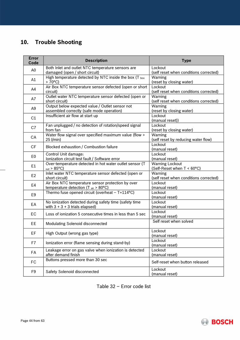
10. Trouble Shooting
Error Code
Description Type
A0 Both Inlet and outlet NTC temperature sensors are damaged (open / short circuit)
Lockout (self reset when conditions corrected)
A1 High temperature detected by NTC inside the box (T box > 70ºC)
Warning (reset by closing water)
A4 Air Box NTC temperature sensor defected (open or short circuit)
Lockout (self reset when conditions corrected)
A7 Outlet water NTC temperature sensor defected (open or short circuit)
Warning (self reset when conditions corrected)
A9 Output below expected value / Outlet sensor not assembled correctly (safe mode operation)
Warning (reset by closing water)
C1 Insufficient air flow at start up
Lockout (manual reset))
C7 Fan unplugged / no detection of rotation/speed signal from fan
Lockout (reset by closing water)
CA Water flow signal over specified maximum value (flow > 25 l/min)
Warning (self reset by reducing water flow)
CF Blocked exhaustion / Combustion failure Lockout (manual reset)
E0 Control Unit damage: Ionization circuit test fault / Software error
Lockout (manual reset)
E1 Over-temperature detected in hot water outlet sensor (T
out > 85ºC) Warning Lockout (Self-Reset when T < 60ºC)
E2 Inlet water NTC temperature sensor defected (open or short circuit)
Warning (self reset when conditions corrected)
E4 Air Box NTC temperature sensor protection by over temperature detection (T air > 80ºC)
Lockout (manual reset)
E9 Thermo fuse opened circuit (overheat – T=114ºC)
Lockout (manual reset)
EA No ionization detected during safety time (safety time with 3 + 3 + 3 trials elapsed)
Lockout (manual reset)
EC Loss of ionization 5 consecutive times in less than 5 sec Lockout (manual reset)
EE Modulating Solenoid disconnected Self reset when solved
EF High Output (wrong gas type) Lockout (manual reset)
F7 Ionization error (flame sensing during stand-by) Lockout (manual reset)
FA Leakage error on gas valve when ionization is detected after demand finish
Lockout (manual reset)
FC Buttons pressed more than 30 sec
Self-reset when button released
F9 Safety Solenoid disconnected Lockout (manual reset)
Table 32 – Error code list

Page 45 from 63
8.1) Problems without error codes
Combustion noise too high
No Convert appliance according IM (check existence of EF codes in
memory)
Gas supply type according appliance gas type ?
Gas supply pressure (static / dynamic) according IM ?
Assure gas supply pressure, testing appliance at
maximum and minimum
In case of need contact gas supplier
Yes
No
Check exhaustion system for eventual recirculation of
combustion products (cross contamination)
Cross contamination persist / Combustion
not ok
Clearances for air admission / flue discharge according IM / Sealing between flue pipes
and appliance
Measure CO2 value (at flue measurement point) in maximum power with /
without front cover
Without Front Cover CO2 (G20) ≈ 5.5% (+/-0.2%) CO2 (G31) ≈ 6.6% (+/-0.2%)
Temp gases máx ≈ 170ºC Temp. gases min ≈ 45ºC
With Front Cover
Máx CO2 = CO2 without front cover + 0.3 %
Yes
Yes
No
No
Adjust appliance by confirming ΔP1 / ΔP2
according IM Note: check air / gas
measurement independently to be sure reading is ≠ 0 and then
check ΔP
Problem solved ?
Emissions according specification ?
End
End
ATTENTION: CO2 > nominal = flue
recirculation CO2 increasing > 0.3%
difference from cover Off to cover On = flue recirculation
ATTENTION: Adjustments of ΔP are done
without front cover
Page 46 from 63
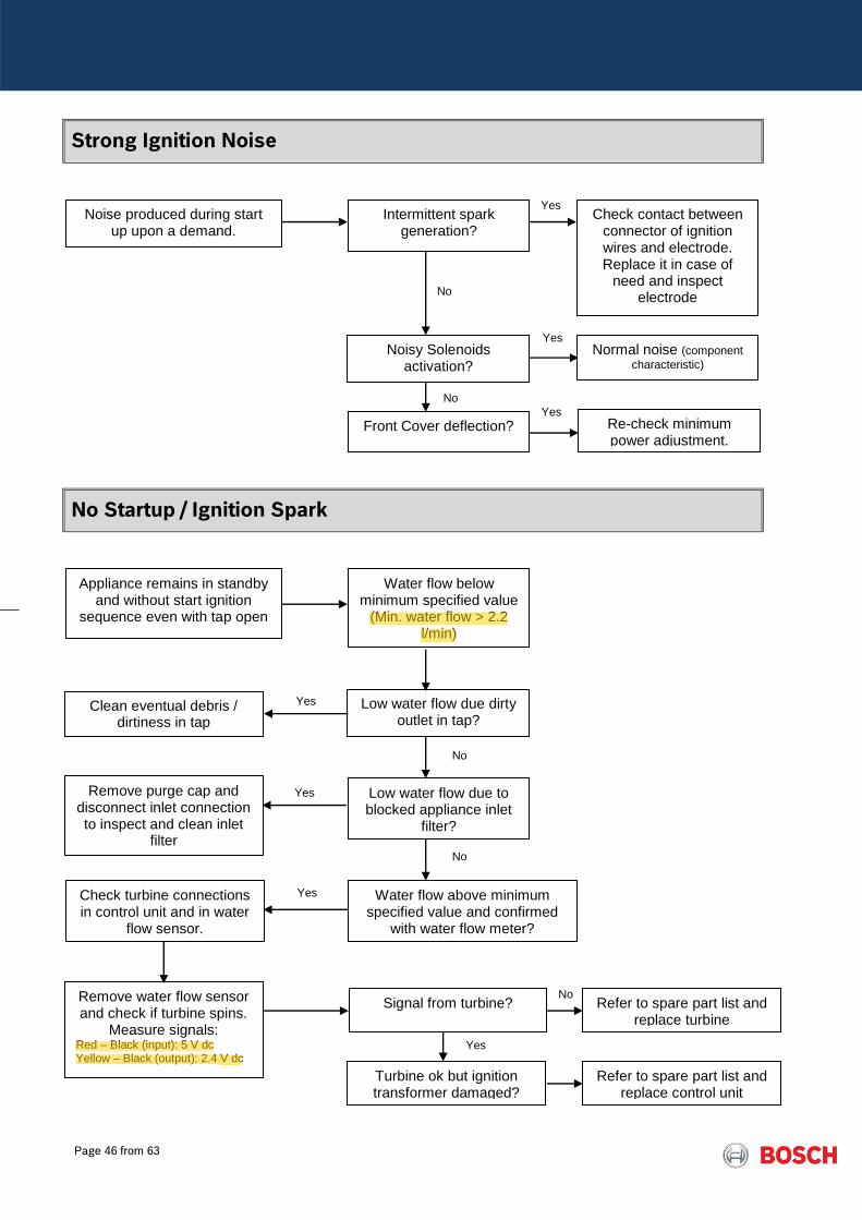
Strong Ignition Noise
No Startup / Ignition Spark
Noise produced during start up upon a demand.
Noisy Solenoids activation?
Check contact between connector of ignition wires and electrode. Replace it in case of
need and inspect electrode
Yes
No
Front Cover deflection?
Re-check minimum power adjustment.
Intermittent spark generation?
Yes
No
Normal noise (component characteristic)
Appliance remains in standby and without start ignition
sequence even with tap open
Low water flow due dirty outlet in tap?
Yes
Low water flow due to blocked appliance inlet
filter?
Water flow below minimum specified value
(Min. water flow > 2.2 l/min)
)
No
Clean eventual debris / dirtiness in tap
Remove purge cap and disconnect inlet connection to inspect and clean inlet
filter
Yes
Water flow above minimum specified value and confirmed
with water flow meter?
No
Check turbine connections in control unit and in water
flow sensor.
Yes
Remove water flow sensor and check if turbine spins.
Measure signals: Red – Black (input): 5 V dc Yellow – Black (output): 2.4 V dc
Signal from turbine? Refer to spare part list and replace turbine
Yes
Turbine ok but ignition transformer damaged?
Refer to spare part list and replace control unit
No
Yes
Alister
Highlight
Alister
Highlight
Alister
Highlight
Alister
Highlight

Page 47 from 63
8.2) Problems with Error Codes
A0 Fault in both inlet and outlet NTC sensor
Component Characteristic: NTC temperature sensor (10 kΩ type)
Lock Out Error Burner shutdown and manual reset necessary
The Inlet / Outlet NTC sensor is interrupted
or in short circuit
Ensure NTC wire is attached in NTC sensor
Unplug Wires and measure the NTC electrical resistance [R] (Ω)
[R] > 30 kΩ or < 0.5 kΩ
[R] = ∞ Ω
NTC values out of range
NTC interrupted
Replace NTC
Plug NTC connection wire and turn ON unit
Problem solved?
End
Change wiring
Problem solved?
Replace control unit
See spare part list
See spare part list
Refer to table with values in Service
Manual
Yes
No
No
Yes
No
No
Yes
Yes
ATTENTION: Red wires – outlet NTC Blue wires – inlet NTC
Page 48 from 63
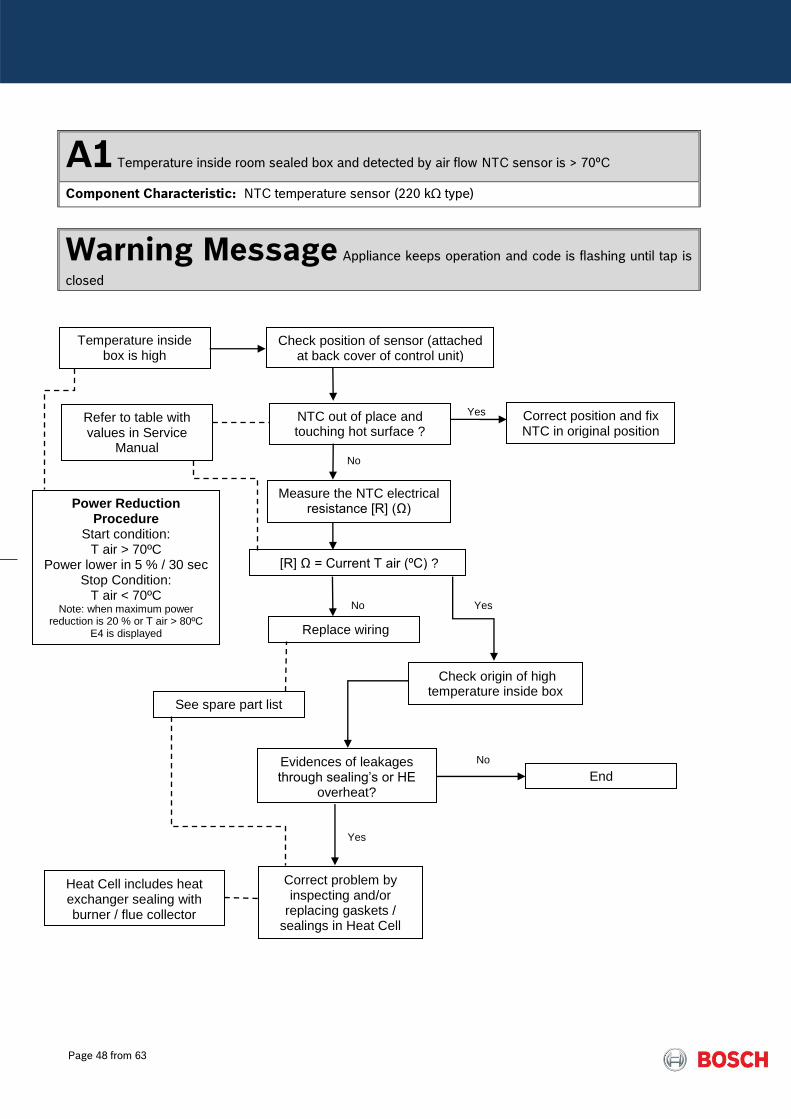
A1 Temperature inside room sealed box and detected by air flow NTC sensor is > 70ºC
Component Characteristic: NTC temperature sensor (220 kΩ type)
Warning Message Appliance keeps operation and code is flashing until tap is
closed
Temperature inside box is high
Check position of sensor (attached at back cover of control unit)
NTC out of place and touching hot surface ?
Measure the NTC electrical resistance [R] (Ω)
[R] Ω = Current T air (ºC) ?
Correct position and fix NTC in original position
Replace wiring
Check origin of high temperature inside box
Evidences of leakages through sealing’s or HE
overheat?
End
Correct problem by inspecting and/or
replacing gaskets / sealings in Heat Cell
See spare part list
Yes
No
No
Yes
No
Yes
Refer to table with values in Service
Manual
Power Reduction Procedure
Start condition: T air > 70ºC
Power lower in 5 % / 30 sec Stop Condition:
T air < 70ºC Note: when maximum power
reduction is 20 % or T air > 80ºC E4 is displayed
Heat Cell includes heat exchanger sealing with burner / flue collector

Page 49 from 63
A4 Fault in the air flow NTC sensor
Component Characteristic: NTC temperature sensor (220 kΩ)
Lock Out Error Burner shutdown
The Air NTC sensor is interrupted or in short
circuit
Assure NTC cable harness is connected in control unit
Unplug the NTC connection and measure the NTC electrical resistance [R] (Ω)
[R] > 1300 kΩ or < 8.2 kΩ
[R] = ∞ Ω
NTC values out of range
NTC interrupted
Change wiring
Plug connection wire and turn ON unit
Problem solved?
End
Change wiring
Problem solved?
Replace control unit
See spare part list
See spare part list
Refer to table with values in Service
Manual
Yes
No
No
Yes
No
No
Yes
Yes
Page 50 from 63
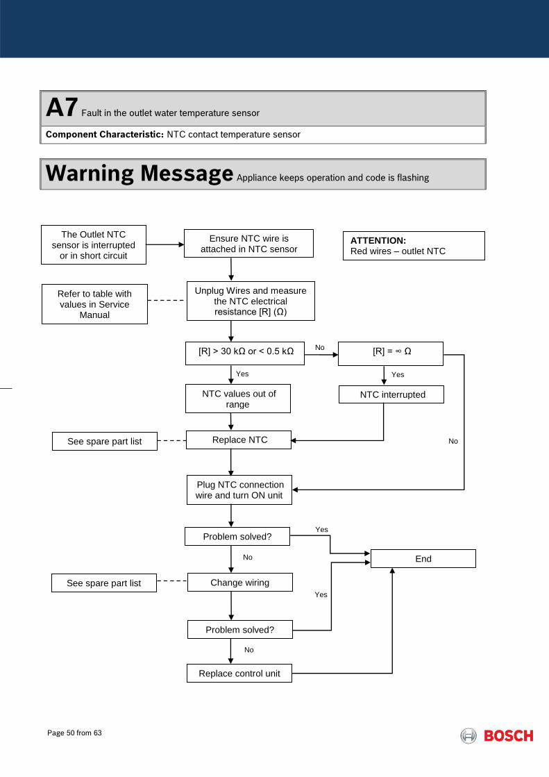
A7 Fault in the outlet water temperature sensor
Component Characteristic: NTC contact temperature sensor
Warning Message Appliance keeps operation and code is flashing
The Outlet NTC sensor is interrupted
or in short circuit
[R] > 30 kΩ or < 0.5 kΩ
[R] = ∞ Ω
NTC values out of range
NTC interrupted
Replace NTC
Plug NTC connection wire and turn ON unit
Problem solved?
End
Change wiring
Problem solved?
Replace control unit
See spare part list
See spare part list
Refer to table with values in Service
Manual
Yes
No
No
Yes
No
No
Yes
Yes
ATTENTION: Red wires – outlet NTC
Ensure NTC wire is attached in NTC sensor
Unplug Wires and measure the NTC electrical resistance [R] (Ω)
Page 51 from 63
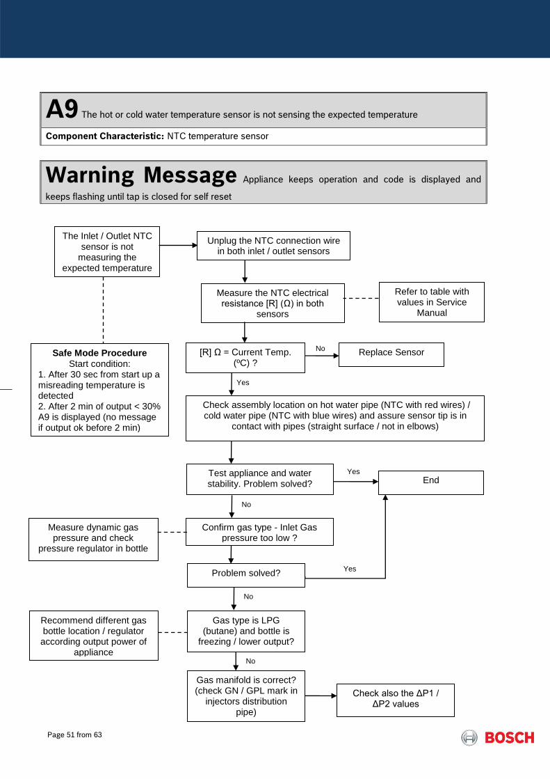
A9 The hot or cold water temperature sensor is not sensing the expected temperature
Component Characteristic: NTC temperature sensor
Warning Message Appliance keeps operation and code is displayed and
keeps flashing until tap is closed for self reset
Safe Mode Procedure Start condition:
1. After 30 sec from start up a misreading temperature is detected 2. After 2 min of output < 30% A9 is displayed (no message if output ok before 2 min)
The Inlet / Outlet NTC sensor is not
measuring the expected temperature
Unplug the NTC connection wire in both inlet / outlet sensors
Measure the NTC electrical resistance [R] (Ω) in both
sensors
[R] Ω = Current Temp. (ºC) ?
Replace Sensor
Refer to table with values in Service
Manual
Yes
No
Check assembly location on hot water pipe (NTC with red wires) / cold water pipe (NTC with blue wires) and assure sensor tip is in
contact with pipes (straight surface / not in elbows)
Test appliance and water stability. Problem solved? End
Yes
Confirm gas type - Inlet Gas pressure too low ?
No
Measure dynamic gas pressure and check
pressure regulator in bottle
Gas type is LPG (butane) and bottle is
freezing / lower output?
Problem solved? Yes
No
Recommend different gas bottle location / regulator according output power of
appliance
Gas manifold is correct? (check GN / GPL mark in
injectors distribution pipe)
Check also the ΔP1 / ΔP2 values
No
Page 52 from 63
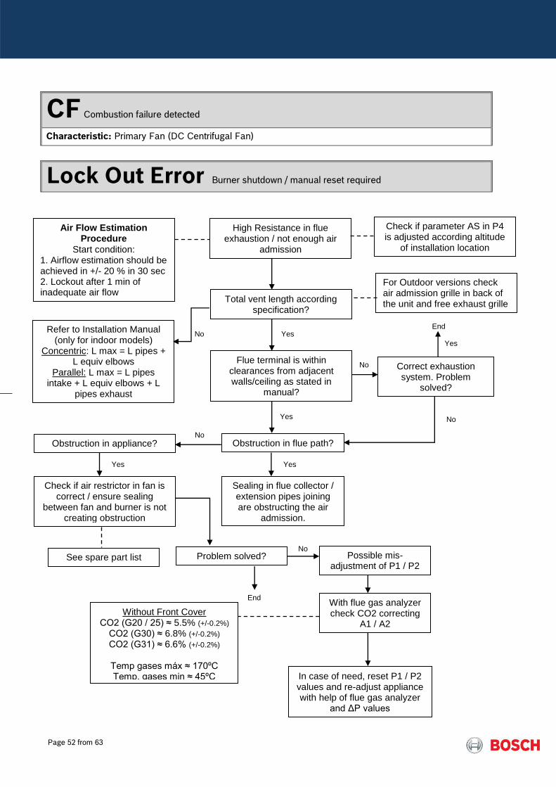
CF Combustion failure detected
Characteristic: Primary Fan (DC Centrifugal Fan)
Lock Out Error Burner shutdown / manual reset required
Air Flow Estimation Procedure
Start condition: 1. Airflow estimation should be achieved in +/- 20 % in 30 sec 2. Lockout after 1 min of inadequate air flow
High Resistance in flue exhaustion / not enough air
admission
Total vent length according specification?
Flue terminal is within clearances from adjacent walls/ceiling as stated in
manual?
Refer to Installation Manual (only for indoor models)
Concentric: L max = L pipes + L equiv elbows
Parallel: L max = L pipes intake + L equiv elbows + L
pipes exhaust
Yes No
Obstruction in flue path?
Yes
No
Possible mis-adjustment of P1 / P2
With flue gas analyzer check CO2 correcting
A1 / A2
Sealing in flue collector / extension pipes joining are obstructing the air
admission.
See spare part list
In case of need, reset P1 / P2 values and re-adjust appliance with help of flue gas analyzer
and ΔP values
Without Front Cover CO2 (G20 / 25) ≈ 5.5% (+/-0.2%)
CO2 (G30) ≈ 6.8% (+/-0.2%) CO2 (G31) ≈ 6.6% (+/-0.2%)
Temp gases máx ≈ 170ºC Temp. gases min ≈ 45ºC
Correct exhaustion system. Problem
solved?
End
Obstruction in appliance?
Check if air restrictor in fan is correct / ensure sealing
between fan and burner is not creating obstruction
Yes
No
Yes
Problem solved? No
End
No
Yes
Check if parameter AS in P4 is adjusted according altitude
of installation location
For Outdoor versions check air admission grille in back of the unit and free exhaust grille

Page 53 from 63
C1 Insufficient air flow at start up
Characteristic: Primary Fan (DC Centrifugal Fan)
Lock Out Error Burner shutdown / manual reset
Total vent length according specification?
Flue terminal is within clearances from adjacent walls/ceiling as stated in
manual?
Refer to Installation Manual Concentric: L max = L pipes +
L equiv elbows Parallel: L max = L pipes
intake + L equiv elbows + L pipes exhaust
Yes No
Obstruction in flue path?
Yes
No
Possible mis-adjustment of P1 / P2
With flue gas analyzer check CO2 values correcting A1 / A2
Sealing in flue collector / extension pipes joining are obstructing the air
admission.
See spare part list
In case of need, reset P1 / P2 values and re-adjust appliance with help of flue gas analyzer
and ΔP values
Without Front Cover CO2 (G20 / 25) ≈ 5.5% (+/-0.2%)
CO2 (G30) ≈ 6.8% (+/-0.2%) CO2 (G31) ≈ 6.6% (+/-0.2%)
Temp gases máx ≈ 170ºC Temp. gases min ≈ 45ºC
Correct exhaustion system. Problem
solved?
End
Obstruction in appliance?
Check if air restrictor in fan is correct / ensure sealing
between fan and burner is not creating obstruction
Yes
No
Yes
Problem solved? No
End
Air Flow Estimation Procedure
Start condition: 1. Airflow estimation should be achieved in +/- 20 % in 20 sec
High Resistance in flue exhaustion / not enough air
admission
No
Yes

Page 54 from 63
C7 No rotational speed sensor signal from primary fan
Characteristic: Primary Fan (DC centrifugal fan)
Lock Out Error appliance enters in lock out immediately
Check bad wire connection in the connector in the back cover of
control unit
Problem solved?
Fan unplugged / cables disconnected or not correctly
attached
Yes
No
Measure output signal from control unit
End
Brown – Blue: 0 – 45 V dc Orange – Blue: 10.8 – 13.2 V dc Yellow – Blue: pulse frequency
Defective Fan
No signal from control unit to fan?
Defective Control Unit
Replace Control Unit
Replace Fan
No Yes
Page 55 from 63
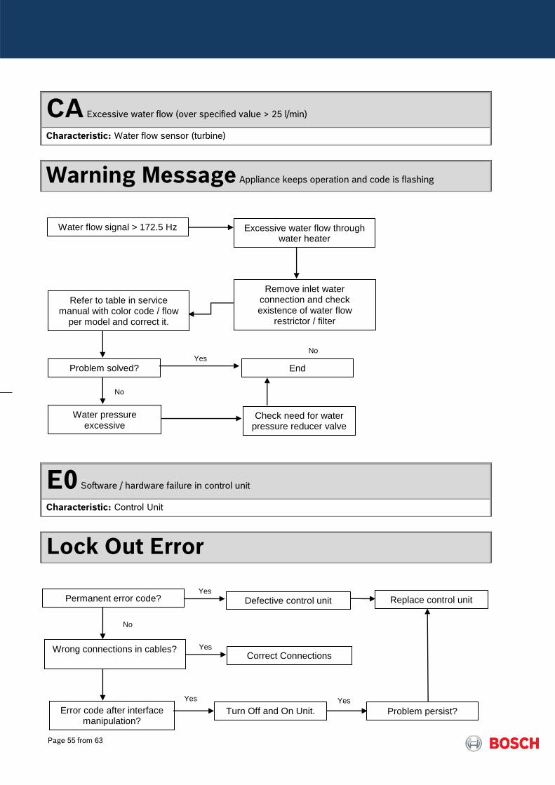
CA Excessive water flow (over specified value > 25 l/min)
Characteristic: Water flow sensor (turbine)
Warning Message Appliance keeps operation and code is flashing
E0 Software / hardware failure in control unit
Characteristic: Control Unit
Lock Out Error
Excessive water flow through water heater
Water pressure excessive
Water flow signal > 172.5 Hz
Yes No
Refer to table in service manual with color code / flow
per model and correct it.
End
Remove inlet water connection and check existence of water flow
restrictor / filter
Problem solved?
No
Check need for water pressure reducer valve
Defective control unit
No
Wrong connections in cables?
Replace control unit
Turn Off and On Unit.
Permanent error code? Yes
Correct Connections Yes
Error code after interface manipulation?
Yes
Problem persist?
Yes
Page 56 from 63
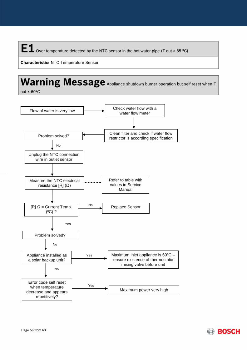
E1 Over temperature detected by the NTC sensor in the hot water pipe (T out > 85 ºC)
Characteristic: NTC Temperature Sensor
Warning Message Appliance shutdown burner operation but self reset when T
out < 60ºC
Error code self reset when temperature
decrease and appears repetitively?
Yes
No
Problem solved?
Maximum inlet appliance is 60ºC – ensure existence of thermostatic
mixing valve before unit
Clean filter and check if water flow restrictor is according specification
Appliance installed as a solar backup unit?
No
Flow of water is very low Check water flow with a
water flow meter
Yes
Maximum power very high
Unplug the NTC connection wire in outlet sensor
Measure the NTC electrical resistance [R] (Ω)
[R] Ω = Current Temp. (ºC) ?
Replace Sensor
Refer to table with values in Service
Manual
No
Problem solved?
No
Yes
Page 57 from 63
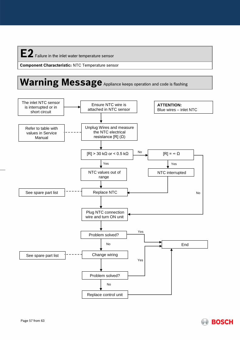
E2 Failure in the inlet water temperature sensor
Component Characteristic: NTC Temperature sensor
Warning Message Appliance keeps operation and code is flashing
The inlet NTC sensor is interrupted or in
short circuit
[R] > 30 kΩ or < 0.5 kΩ
[R] = ∞ Ω
NTC values out of range
NTC interrupted
Replace NTC
Plug NTC connection wire and turn ON unit
Problem solved?
End
Change wiring
Problem solved?
Replace control unit
See spare part list
See spare part list
Refer to table with values in Service
Manual
Yes
No
No
Yes
No
No
Yes
Yes
ATTENTION: Blue wires – inlet NTC
Ensure NTC wire is attached in NTC sensor
Unplug Wires and measure the NTC electrical resistance [R] (Ω)

Page 58 from 63
E4 Air box NTC sensor detect high temperature inside room sealed box (Tbox > 80ºC)
Characteristic: NTC Temperature sensor
Lock Out Error Burner shutdown but self reset by closing water
Temperature inside box reach high limit
(Tbox > 80ºC)
Check position of sensor (attached at back cover of control unit)
NTC out of place and touching hot surface ?
Measure the NTC electrical resistance [R] (Ω)
[R] Ω = Current T air (ºC) ?
Correct position and fix NTC in original position
Replace wiring
Check origin of high temperature inside box
Evidences of leakages through sealing’s or HE
overheat?
End
Correct problem by inspecting and/or
replacing gaskets / sealings in Heat Cell
See spare part list
Yes
No
No
Yes
No
Yes
Refer to table with values in Service
Manual
Heat Cell includes heat exchanger sealing with burner / flue collector
Problem solved?
Yes
No
Excessive burner power
Check CO2 emissions and reduce
power in L1 / A1 to correct ΔP1
Page 59 from 63
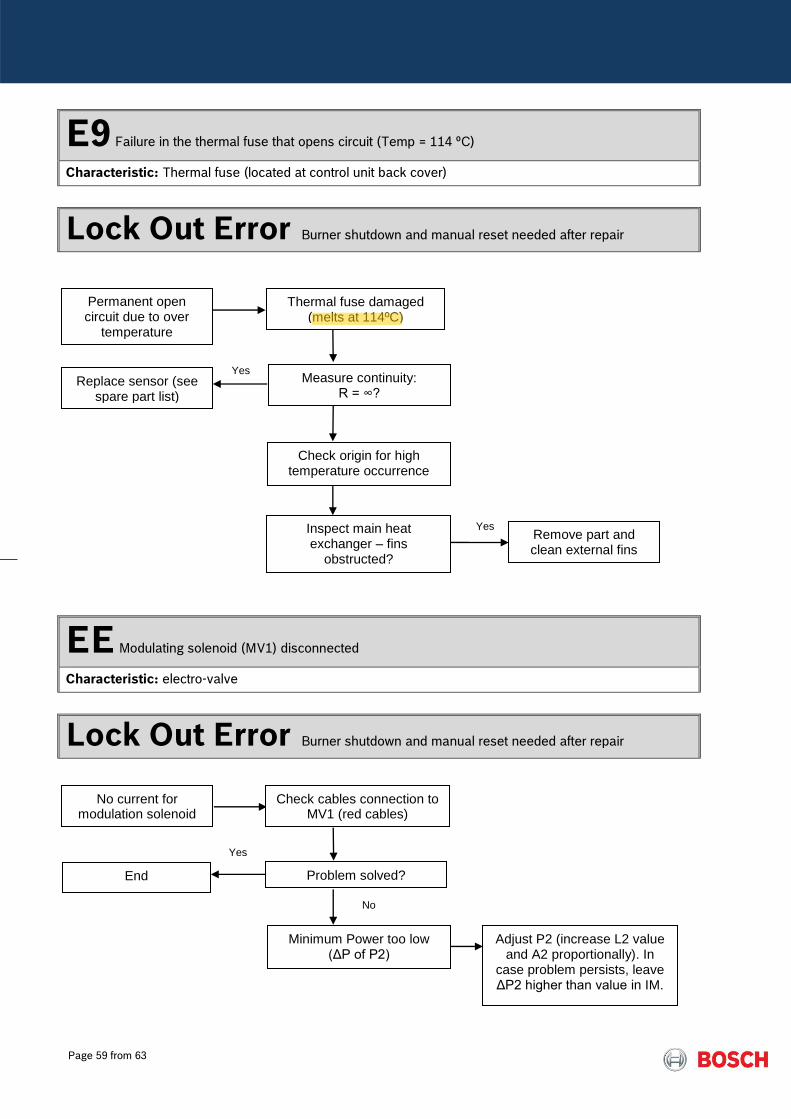
E9 Failure in the thermal fuse that opens circuit (Temp = 114 ºC)
Characteristic: Thermal fuse (located at control unit back cover)
Lock Out Error Burner shutdown and manual reset needed after repair
EE Modulating solenoid (MV1) disconnected
Characteristic: electro-valve
Lock Out Error Burner shutdown and manual reset needed after repair
Permanent open circuit due to over
temperature
Thermal fuse damaged (melts at 114ºC)
Measure continuity: R = ∞?
Check origin for high temperature occurrence
Replace sensor (see spare part list)
Yes
Inspect main heat exchanger – fins
obstructed?
Yes Remove part and clean external fins
Problem solved?
Minimum Power too low (ΔP of P2)
End
Yes
No current for modulation solenoid
Check cables connection to MV1 (red cables)
No
Adjust P2 (increase L2 value and A2 proportionally). In
case problem persists, leave ΔP2 higher than value in IM.
Alister
Highlight
Page 60 from 63
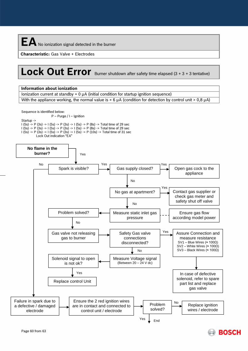
EA No ionization signal detected in the burner
Characteristic: Gas Valve + Electrodes
Lock Out Error Burner shutdown after safety time elapsed (3 + 3 + 3 tentative)
Information about ionization
Ionization current at standby = 0 µA (initial condition for startup ignition sequence)
With the appliance working, the normal value is ≈ 6 µA (condition for detection by control unit > 0,8 µA)
Sequence is identified below:
P – Purge / I – Ignition
Startup -> I (5s) -> P (3s) -> I (5s) -> P (3s) -> I (5s) -> P (8s) -> Total time of 29 sec I (5s) -> P (3s) -> I (5s) -> P (3s) -> I (5s) -> P (8s) -> Total time of 29 sec I (5s) -> P (3s) -> I (5s) -> P (3s) -> I (5s) -> P (10s) -> Total time of 31 sec
Lock Out indication “EA”
No flame in the
burner?
Spark is visible? Gas supply closed? Open gas cock to the appliance
Yes
No
Contact gas supplier or check gas meter and safety shut off valve
No gas at apartment?
Yes Yes
Yes
No
Problem solved? Measure static inlet gas pressure
Gas valve not releasing gas to burner
Safety Gas valve connections
disconnected?
Assure Connection and measure resistance
SV1 – Blue Wires (≈ 100Ω) SV2 – White Wires (≈ 100Ω) SV3 – Black Wires (≈ 100Ω)
No
Yes
Solenoid signal to open is not ok?
No
Measure Voltage signal (Between 20 – 24 V dc)
Replace control Unit
No
Ensure gas flow according model power
In case of defective solenoid, refer to spare
part list and replace gas valve
Yes
Failure in spark due to a defective / damaged
electrode
Ensure the 2 red ignition wires are in contact and connected to
control unit / electrode
Problem solved?
Replace ignition wires / electrode
Yes End
No
Page 61 from 63
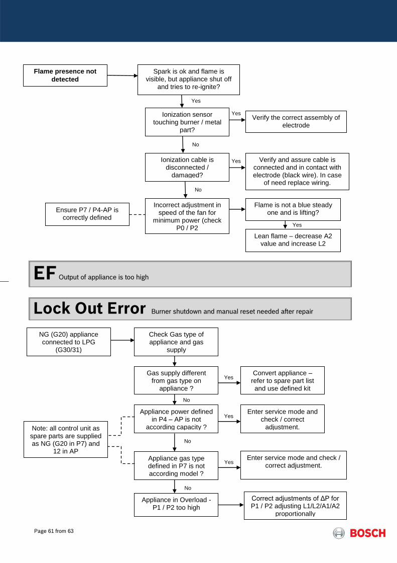
EF Output of appliance is too high
Lock Out Error Burner shutdown and manual reset needed after repair
Flame presence not
detected
NG (G20) appliance connected to LPG
(G30/31)
Check Gas type of appliance and gas
supply
Gas supply different from gas type on
appliance ?
Convert appliance – refer to spare part list and use defined kit
Yes
No
Appliance in Overload - P1 / P2 too high
Correct adjustments of ΔP for P1 / P2 adjusting L1/L2/A1/A2
proportionally
Appliance power defined in P4 – AP is not
according capacity ?
Enter service mode and check / correct
adjustment.
Yes
Note: all control unit as spare parts are supplied as NG (G20 in P7) and
12 in AP
No
Appliance gas type defined in P7 is not according model ?
Enter service mode and check / correct adjustment.
Yes
No
Spark is ok and flame is visible, but appliance shut off
and tries to re-ignite?
Ionization sensor touching burner / metal
part?
Verify the correct assembly of electrode
Yes
Ionization cable is disconnected /
damaged?
Verify and assure cable is connected and in contact with electrode (black wire). In case
of need replace wiring.
No
Yes
Yes
No
Incorrect adjustment in speed of the fan for
minimum power (check P0 / P2
Flame is not a blue steady one and is lifting? Ensure P7 / P4-AP is
correctly defined
Lean flame – decrease A2 value and increase L2
Yes

Page 62 from 63
F7 Ionization detected with appliance in standby
Characteristic: Ionization system
Lock Out Error Burner shutdown
F9 Safety solenoid valve disconnected
Characteristic: electro valve
Lock Out Error Burner shutdown
Loose or bad connection between cable and
electrode
Assure black wire is securely connected to
the set of electrode
Ionization cable damaged / defective
isolation ?
Replace wiring and assure connection in
electrode
Yes
No
Ionization electrode damaged?
Replace electrode Yes
Verify wires connection: SV1 – blue wires SV2 – white wires SV3 – black wires
Measure resistance of SV ≈ 99.7 Ω
No
Loose connection in safety solenoid (SV1 /
SV2 / SV3)
Problem solved?
Replace gas valve
Replace control unit
No
Page 63 from 63
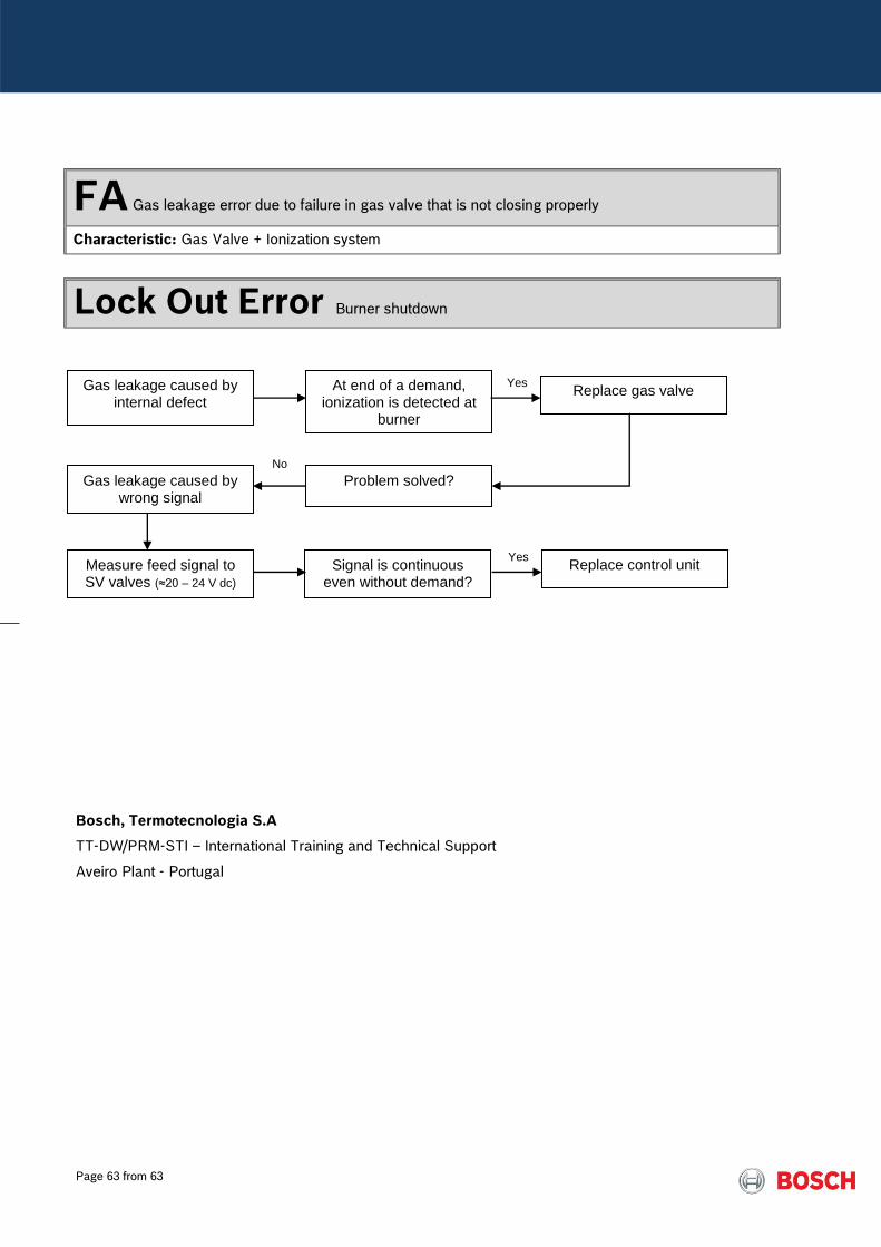
FA Gas leakage error due to failure in gas valve that is not closing properly
Characteristic: Gas Valve + Ionization system
Lock Out Error Burner shutdown
Bosch, Termotecnologia S.A
TT-DW/PRM-STI – International Training and Technical Support
Aveiro Plant - Portugal
At end of a demand, ionization is detected at
burner
Replace gas valve
No
Gas leakage caused by internal defect
Problem solved?
Gas leakage caused by
wrong signal
Measure feed signal to SV valves (≈20 – 24 V dc)
Signal is continuous even without demand?
Yes
Replace control unit Yes