INSTALLER: Leave this manual with the appliance....
72
WARNING If not installed, operated and maintained in accordance with the manufacturer's instruc- tions, this product could expose you to sub- stances in fuel or from fuel combustion which can cause death or serious illness. WARNING If the information in these instructions are not followed exactly, a fire or explosion may result causing property damage, personal injury or loss of life. Installation and service must be performed by a qualified installer, service agency or the gas supplier. INSTALLATION INSTRUCTIONS AND OWNER'S MANUAL INSTALLER: Leave this manual with the appliance. CONSUMER: Retain this manual for future reference. OUTDOOR LINEAR GAS FIREPLACE MODELS OLL60FP12S(N,P)-1 OLL60SP12S(N,P)-1 GAS-FIRED ! DANGER CARBON MONOXIDE HAZARD This appliance can produce carbon monoxide which has no odor. Using it in an enclosed space can kill you. Never use this appliance in an enclosed space such as a camper, tent, car or home. WARNING For Outdoor Use Only. WARNING If you smell gas: 1. Shut off gas to the appliance. 2. Extinguish any open flame. 3. If odor continues, keep away from the appliance and immediately call your gas supplier or fire department. WARNING Improper installation, adjustment, altera- tion, service or maintenance can cause injury or property damage. Read the instal- lation, operating and maintenance instruc- tions thoroughly before installing or servic- ing this equipment. WARNING Do not store or use gasoline or other flam- mable vapors and liquids in the vicinity of this or any other appliance. An LP-cylinder not connected for use shall not be stored in the vicinity of this or any other appliance. Page 1
Transcript of INSTALLER: Leave this manual with the appliance....

WARNINGIf not installed, operated and maintained in accordance with the manufacturer's instruc-tions, this product could expose you to sub-stances in fuel or from fuel combustion which can cause death or serious illness.
WARNINGIf the information in these instructions are not followed exactly, a fire or explosion may result causing property damage, personal injury or loss of life.
Installation and service must be performed by a qualified installer, service agency or the gas supplier.
INSTALLATION INSTRUCTIONSAND OWNER'S MANUAL
INSTALLER: Leave this manual with the appliance.CONSUMER: Retain this manual for future reference.
OUTDOOR LINEAR GAS FIREPLACE
MODELSOLL60FP12S(N,P)-1OLL60SP12S(N,P)-1
GAS-FIRED
! DANGERCARBON MONOXIDE HAZARD
This appliance can produce carbon monoxide which has no odor.Using it in an enclosed space can kill you.Never use this appliance in an enclosed space such as a camper, tent, car or home.
WARNINGFor Outdoor Use Only.
WARNINGIf you smell gas:1. Shut off gas to the appliance.2. Extinguish any open flame.3. If odor continues, keep away from the
appliance and immediately call your gas supplier or fire department.
WARNINGImproper installation, adjustment, altera-tion, service or maintenance can cause injury or property damage. Read the instal-lation, operating and maintenance instruc-tions thoroughly before installing or servic-ing this equipment.
WARNINGDo not store or use gasoline or other flam-mable vapors and liquids in the vicinity of this or any other appliance.An LP-cylinder not connected for use shall not be stored in the vicinity of this or any other appliance.
Page 1

35008-6-0317Page 2
BEFORE YOU START1. Read the safety information on pages 4 to 5.2. What to consider before installing. See Page 11.3. Water drainage is required. See page 12. Optional drain tray
available.4. Where are you going to install the unit? See pages 11 to 13.5. Frame the opening. See pages 8 to 10 and 14 to 15.6. Installthefireplace.Seepages14to16.7. Connect the electricity. See pages 16 and 26.8. Connect the gas. See page 17 to 19.9. Install the crushed glass. See page 22.10. Lightthefireplaceandtroubleshoot.Seepages23and28.11. Showthehomeownerhowtooperatethefireplace.See
page 25. 12. Show the homeowner how to do the basic maintenance. See
page 27.
Tools Needed:(1) - 1/8-inch Allen Wrench(2) - Adjustalbe wrenches with range of 1-inch for gas connection(2) - Adjustable pipe wrenches(1) - Phillips Screwdriver
CARTON CONTENTS
INDEX NO. DESCRIPTION
QUANTITYSUPPLIED
OLL60FP OLL60SP1 Glass Panel 1 22 Non-Combustible Panel - Top 1 23 Non-Combustible Panel - Side 2 44 Envelope 1 15 Nailing Flange 4 86 Receptacle 1 17 Cover Plate 1 18 Conduit Connector 1/2-in. 1 19 AA Battery 1 1
10 Burner Service Support 2 2
See Parts Lists on pages 30 to 33 for ordering replacement parts. Do not order batteries, bolts, screws, washers or nuts. They are standard hardware items and can be purchased at any local hardware store.
1
6
2
3
5
7
4
8 9
10
HARDWARE PACK CONTENTS
1-1/4” PHILLIPS SELF-DRILLING SCREW
(
)
6 - OLL60FP12S(N,P))
(12 - OLL60SP12S(N,P)
#10-32 X ½” STAINLESS HEX HEAD SCREW
(8 - OLL60FP12S(N,P))
(16 - OLL60SP12S(N,P))

35008-6-0317 Page 3
TABLE OF CONTENTS
BEFORE YOU START ...................................................................................................................2TABLE OF CONTENTS.................................................................................................................3IMPORTANT SAFETY INFORMATION .........................................................................................4SAFETY INFORMATION FOR USERS OF LP-GAS ....................................................................5INTRODUCTION ...........................................................................................................................6SPECIFICATIONS .........................................................................................................................7ACCESSORIES .............................................................................................................................7COMBUSTIBLE MATERIALS .......................................................................................................8CLEARANCES ........................................................................................................................ 8 - 9FIREPLACE DIMENSIONS .........................................................................................................10PLANNING INSTALLATION ................................................................................................11 - 13FIREPLACE INSTALLATION .......................................................................................................... - FRAMING & INSTALLATION ........................................................................................... 14 - 15
- ELECTRICAL SUPPLY ............................................................................................................16
- GAS SUPPLY ..........................................................................................................................17
- LP-GAS CYLINDER INFORMATION............................................................................... 18 - 19
- FINISHING ....................................................................................................................... 20 - 22
LIGHTING INSTRUCTIONS ........................................................................................................23MAIN BURNER FLAME CHARACTERISTICS ...........................................................................24OPERATION INSTRUCTIONS / FLAME APPEARANCE ..........................................................25WIRING ........................................................................................................................................26MAINTENANCE ..........................................................................................................................27TROUBLESHOOTING ................................................................................................................28MASTER PARTS DISTRIBUTOR LIST .......................................................................................29HOW TO ORDER REPAIR PARTS .............................................................................................29OLL60FP PARTS LIST ................................................................................................................30OLL60FP PARTS VIEW ..............................................................................................................31OLL60SP PARTS LIST ...............................................................................................................32OLL60SP PARTS VIEW ..............................................................................................................33FIREPLACE SERVICE HISTORY ...............................................................................................34WARRANTY TERMS ...................................................................................................................35
SECTION PAGE

35008-6-0317Page 4
IMPORTANT SAFETY INFORMATIONDANGER: Indicates a hazardous situation which, if not
avoided, will result in death or serious injury.
WARNING: Indicates a hazardous situation which, if not avoided, could result in death or serious injury.
CAUTION: Indicates a hazardous situation which, if not avoided, could result in minor or moderate injury.NOTICE: Addresses practices not related to personal injury.
WARNINGDo not place debris, logs, or other articles in fireplace during operation.
WARNINGAny modification to controls can be dangerous. Improper installation or use of the gas log set can cause serious injury or death from fire, burns, explosion or carbon monoxide poisoning.
WARNINGMake a periodic visual check of burners. Clean and replace damaged parts.
DANGERChildren and adults should be alerted to the hazard of high surface temperature and should stay away to avoid burns or clothing ignition.
DANGERYoung children should be carefully supervised when they are in the same area with the fireplace.
DANGERClothing or other flammable materials should not be hung from the fireplace, or placed on or near the fireplace.
DANGERKeep the fireplace area clear and free from combustible material, gasoline and other flammable vapors and liquids.
• Installer: Please leave these instructions with the owner for future reference
• This unit complies with ANSI Z21.97/CSA 2.41 for Outdoor Gas Fireplaces.
• Installation and repair should be done by a QUALIFIED SERVICE PERSON. This fireplace should be inspected before use and at least annually by a professional service person. More frequent cleaning may be required due to insects, pollen build up, dust, etc. It is imperative that the control compartments, burners, and circulating air passageways of the fireplace be kept clean.
• During manufacturing, fabricating and shipping, various components of this fireplace are treated with certain oils, films or bonding agents. These agents are not harmful, but may produce annoying smoke and smells as they are burned off during initial operation of the fireplace. This is a normal temporary occurrence.
• Follow all local codes regarding installation, combustion and ventilation air or in the absence of local codes follow the National Fuel Gas Code ANSI Z223.1 (US installation), or CAN/CGA-B149, installation Code (Canada installation).
• Inspect the burner at least once a year.
• Keep burner and control compartment clean. • DO NOT use this fireplace if any part has been under water.
Immediately call a qualified service technician to inspect the fireplace and to replace any part of the control system and any gas control which has been under water.
• Any guard or other protective device removed for servicing the appliance must be replaced prior to operating the appliance.

35008-6-0317 Page 5
SAFETY INFORMATION FOR USERS OF LP-GASPropane (LP-Gas) is a flammable gas which can cause fires and explosions. In its natural state, propane is odorless and colorless. You may not know all the following safety precautions which can protect both you and your family from an accident. Read them carefully now, then review them point by point with the members of your household. Someday when there may not be a minute to lose, everyone’s safety will depend on knowing exactly what to do. If, after reading the following information, you feel you still need more information, please contact your gas supplier.
LP-GAS WARNING ODOR
If a gas leak happens, you should be able to smell the gas because of the odorant put in the LP-Gas.
That's your signal to go into immediate action!
• Donotoperateelectricswitches,lightmatches,useyourphone.Do not do anything that could ignite the gas.
• Geteveryoneoutofthebuilding,vehicle,trailer,orarea.Dothat IMMEDIATELY.
• Closeallgastankorcylindersupplyvalves.
• LP-Gasisheavierthanairandmaysettleinlowareassuchasbasements.Whenyouhavereasontosuspectagasleak,keepoutofbasementsandotherlowareas.Stayoutuntilfirefightersdeclare them to be safe.
• Useyourneighbor’sphoneandcallatrainedLP-Gasserviceperson and the fire department. Even though youmay notcontinue to smell gas, do not turn on the gas again. Do not re-enter the building, vehicle, trailer, or area.
• Finally, lettheservicemanandfirefighterscheckforescapedgas. Have them air out the area before you return. Properly trained LP-Gas service people should repair the leak, thencheckandrelightthegasfireplaceforyou.
NO ODOR DETECTED - ODOR FADESome people cannot smell well. Some people cannot smell the odor of the chemical put into the gas. You must find out if you can smell the odorant in propane.Smokingcandecreaseyour ability to smell. Being around an odor for a time can affect your sensitivity or ability to detect that odor. Sometimes other odors in theareamaskthegasodor.Peoplemaynotsmellthegasodorortheirmindsareonsomethingelse.Thinkingaboutsmellingagasodorcanmakeiteasiertosmell.
The odorant in LP-gas is colorless, and it can fade under some circumstances. Forexample,ifthereisanundergroundleak,themovementofthegasthroughsoilcanfiltertheodorant.OdorantsinLP-Gas also are subject to oxidation. This fading can occur if there isrustinsidethestoragetankorinirongaspipes.
The odorant in escaped gas can adsorb or absorb onto or into walls, masonry and other materials and fabrics in a room. That will takesomeoftheodorantoutofthegas,reducingitsodorintensity.
LP-Gas may stratify in a closed area, and the odor intensity could vary at different levels. Since it is heavier than air, there may be more odor at lower levels. Always be sensitive to the slightest gas odor.Ifyoudetectanyodor,treatitasaseriousleak.Immediatelygo into action as instructed earlier.
SOME POINTS TO REMEMBER• Learn to recognize the odor of LP-gas. Your local LP-Gas
Dealer can give you a “Scratch and Sniff” pamphlet. Use it to findoutwhatthepropaneodorsmellslike.IfyoususpectthatyourLP-Gashasaweakorabnormalodor,callyourLP-GasDealer.
• Ifyouarenotqualified,donotlightpilotlights,performservice,ormakeadjustmentstofireplacesontheLP-Gassystem.Ifyouarequalified,consciouslythinkabouttheodorofLP-Gasprior to and while lighting pilot lights or performing service or makingadjustments.
• Sometimesabasementor a closed-uphousehasamustysmell that can cover up the LP-Gas odor. Do not try to light pilotlights,performservice,ormakeadjustmentsinanareawhere the conditions are such that you may not detect the odor iftherehasbeenaleakofLP-Gas.
• Odorfade,duetooxidationbyrustoradsorptiononwallsofnewcylindersandtanks,ispossible.Therefore,peopleshouldbeparticularlyalertandcarefulwhennewtanksorcylindersareplacedinservice.Odorfadecanoccurinnewtanks,orreinstalledoldtanks,iftheyarefilledandallowedtosettoolongbeforerefilling.Cylindersandtankswhichhavebeenoutof service for a time may develop internal rust which will cause odor fade. If such conditions are suspected to exist, a periodic sniff test of the gas is advisable. If you have any question about the gas odor, call your LP-gas dealer. A periodic sniff test of the LP-gas is a good safety measure under any condition.
• If,atanytime,youdonotsmelltheLP-Gasodorantandyouthinkyoushould,assumeyouhavealeak.Thentakethesameimmediate action recommended above for the occasion when you do detect the odorized LP-Gas.
• Ifyouexperienceacomplete“gasout,”(thecontainerisundernovaporpressure),turnthetankvalveoffimmediately.Ifthecontainer valve is left on, the container may draw in some air throughopeningssuchaspilotlightorifices.Ifthisoccurs,somenew internal rusting could occur. If the valve is left open, then treatthecontainerasanewtank.Alwaysbesureyourcon-tainer is under vapor pressure by turning it off at the container beforeitgoescompletelyemptyorhavingitrefilledbeforeitiscompletely empty.

35008-6-0317Page 6
PRODUCT SPECIFICATIONS
DECORATIVE CRUSHED GLASSRequired Decorative Crushed Glass Media Kits (10 Sq. Ft. Required for Burner and LED Lighting)
Model DescriptionDG1CLF* Clear Frost
DECORATIVE CRUSHED GLASS (FOR ACCENT ONLY)Model Description
DG1BKP* BlackPolishedDG1BUC* Blue Clear
*Clear Frost Decorative Crushed Glass is required. Decorative Glass Droplets cannot be substituted for crushed glass. One bag of crushed glass covers 1 sq. ft. Enough crushed glass to cover 10 sq. ft. is required. Glass colors may be mixed. The maximum amount of Crushed Decorative Glass allowed is 10 bags. Transparent and Translucent crushed glass will allow LEDs to better shine through.
DECORATIVE GLASS DROPS & DROPLETS (MAY BE USED IN ADDITION TO CRUSHED GLASS AS AN ENHANCEMENT)Model Description
DG1NXS 1-in. Decorative Glass Drops - Onyx SolidDG1RYC 1-in. Decorative Glass Drops - Ruby ClearDG1TZC 1-in. Decorative Glass Drops - Topaz ClearDG1AB 1/2-in. Decorative Glass Droplets - Aqua BlueDG1GC 1/2-in. Decorative Glass Droplets -Glacier IceDG1SL 1/2-in. Decorative Glass Droplets -Sangria Luster
Note: Decorative Glass Droplets may be added on top of the crushed glass as an enhancement. Decorative Glass Droplets must not beplacedintheburnerflame.SeeCrushedGlassInstallation,Page22.DonotaddmorethanonebagofDecorativeglassdroplets.
ACCESSORIESModel Description
DT48LSS StainlessSteelDrainTray-(Fits48and60-in.fireplaces)WD60LSS StainlessSteelWeatherDoor-60-in(ordertwoforsee-throughfireplaces)WG60LT1 DeflectorGlassforWindyApplications-60-in(ordertwoforsee-throughfireplaces)35829 Nat to LP Conversion Kit35830 LP to Nat Conversion Kit
ACCESSORIES
Model Gas Valve Type Orifice BTUH Max. Rate BTUH Min. RateOLL60FP12L NAT MANUAL #14 65,000 39,000OLL60FP12L LP MANUAL #41 65,000 37,000OLL60SP12L NAT MANUAL #14 65,000 39,000OLL60SP12L LP MANUAL #41 65,000 37,000
Natural Gas Propane GasManifold pressure setting 4-1/2" w.c. 11" w.c.
Gas inlet pressure Max. 7" w.c. 11" w.c.Air Shutter Setting 1/16" Open Fully Open

35008-6-0317 Page 7
INTRODUCTIONHearthsshouldslopeawayfromthefrontofthefireplaceandchaseat 1/8 in. to 1/4 in. per foot. Metal safety strips must be on top of any combustible hearth materials used for moisture management.
Whenpurchasingafireboxorfireplacewerecommendyoualsobuy a weather cover to protect the unit from moisture. Never install a burner where moisture cannot drain off easily. We recommend a weather barrier to protect the burner from moisture.
Qualified Installing AgencyInstallation and replacement of gas piping, gas utilization equipment or accessories and repair and servicing of equipment shall be performedonlybyaqualifiedagency.Theterm"qualifiedagency"meansanyindividual,firm,corporationorcompanywhicheitherinperson or through a representative is engaged in and is responsible for (a) the installation or replacement of gas piping or (b) the connection, installation, repair or servicing of equipment, who is experienced in suchwork,familiarwithallprecautionsrequiredandhascompliedwith all the requirements of the authority having jurisdiction.
Local Codes• Whenthefireplaceisconnectedtoafixedpipingsystem,the
installation must conform with local codes, or in the ab-sence of local codes with the National Fuel Gas Code, ANSI Z223.1/NFPA 54, or International Fuel Gas Code.
• Wheninstalled,thefireplacemustbeelectricallygroundedin accordance with local codes, or in the absence of local codes with the National Electrical Code, ANSI/NFPA 70, if applicable.
Commonwealth of Massachusetts: The installation must be madebyalicensedplumberorgasfitterintheCommonwealthof Massachusetts.
The installation must conform with local codes or, in the absence of local codes, with the National Fuel Gas Code, ANSI Z223.1.*
*Available from the American National Standards Institute, Inc. 1430 Broadway, New York, N.Y. 10018.
High AltitudesFor altitudes/elevations above 2,000 feet (610m), ratings should be reduced at the rate of 4 percent for each 1,000 feet (305m) above sea level. Contact the manufacturer or your gas company before changingspud/orificesize.
Well Head Gas InstallationsSome natural gas utilities use "well head" gas. This may affect the Btu output of the unit. Contact the gas company for the heating value. Contact the manufacturer or your gas company before changing spud/orificesize.
Instructions to Installer1. Installer must leave instruction manual with owner after
installation.
2. Installer must have owner fill out and mail registration card supplied with this fireplace or register online at www.empirecomfort.com.
3. Installer should show owner how to start and operate outdoor fireplace.
Always consult your local Building Department regarding regulations, codes or ordinances which apply to the installation of an outdoor gasfireplace.
WARNINGTo avoid injury or damage to the fireplace or surrounding area, do not burn wood or other solid fuels in this fireplace.
WARNINGANY CHANGE TO THIS FIREPLACE OR ITS CONTROLS CAN BE DANGEROUS. Improper installation or use of the fireplace can cause seri-ous injury or death from fire, burns, explosion or carbon monoxide poisoning.
ThisseriesisdesigncertifiedinaccordancewithANSI Z21.97/CSA 2.41 for Outdoor Gas Fireplaces and should be installed according to these instructions.
Any alteration of the original design, installing it other than as shown in these instructions or using a type of gas not shown on the rating plate, is the responsibility of the person and company making the change.Manual Valve Safety SystemWhen the burner ignites, a thermocouple senses a signal (electrical current) that energizes a magnet in the gas valve. After 30 to 60 seconds, thecontrol knobcanbe released. If the thermocoupledoesnotsensetheflame,thegaswillshutoff.
ImportantAll correspondence should refer to complete Model Number, Serial Number and type of gas.
Moisture ResistanceThisoutdoorfireplacewillshedmoderateamountsofwater,butisnot waterproof. Water and condensing water vapor may enter the chase under certain conditions.
Thefireplacewillnotperformasanexteriorwall.Moisturepenetration must be considered for construction that places the fireplace instructure walls or on moisture sensitive surfaces.
When installed on exterior walls: Empire Comfort Systems recommends the fireplace chase be constructed outside thestructure's weather envelope. Where the platform meets the wall, useaflashingdetail similar to that required forattacheddecks.Chase platforms, including hearths should slope away from the structureat1/4in.perfoot.Thefireplacecanbeshimmedlevel.
When installed on surfaces where water may collect or cause damage: Empire Comfort Systems recommends a slope of 1/8 to 1/4in.perfoottowardsthedrainportsuggested.Thefireplacecanbe shimmed level.

35008-6-0317Page 8
CLEARANCES
D
C
E
B
A
F
Index Letter Description
Dimension from Fireplace Opening
(in inches)
A From ground or other combustible surface 10-1/4*
B From Side Walls 6C From Ceiling (minimum) 24D Alcove Width (minimum) 72E Alcove Depth (maximum) 24F Ceiling Height (minimum) 90
*Note: DimensionAincludes3-1/2in.underfireplaceforsupportframing and drain tray installation.
Figure 3 - Alcove Clearances
Minimum Wall and Ceiling ClearancesSidewallClearances:Theclearancefromtheinsideofthefireplaceto any combustible wall should not be less than 6 in.Ceiling Clearances: The ceiling height should not be less than 24 in. from the top opening.Mantel Clearances: If a combustible mantel is installed, it must meet the clearance requirements detailed in Figure 2.
COMBUSTIBLES
ALLOWED
MANTEL
2”
4”
6”
8”
12”
12”
16 13/16”
14 3/8”
19 3/16”
21 5/8”
24”
10”
Figure 2 - Mantel Clearances
Donotattachcombustiblematerialtothemantelofyourfireplace.Thisisafirehazard.
Figure 1
COMBUSTIBLE MATERIALSNogreetingcards,stockingsorornamentationofanytypeshouldbeplacedonorattachedtothefireplace.Thisisaheatingappliance.Theflowofheatcanignitecombustibles.NOTE: Forsee-thrufireplaces,thisappliestobothsidesofthe
unit.
Television ConsiderationsInstallingatelevisionaboveafireplacehasbecomeincreasinglypopular;however,theareaaboveanyfireplacegetshotandmostTV manufacturers recommend against placing their products near a heat source.Ifyouinstallatelevisionabovethisfireplace,EmpireComfortSys-tems accepts no responsibility for damage or injuries. Follow the television manufacturer’s installation instructions, including anyrecommendations regarding proximity to heat sources.IfyouhaveaTVaboveyourfireplace, turnoff thefireplaceandlet it cool completely before servicing or touching any buttons on the TV.

35008-6-0317 Page 9
Figure 4 Front and Side View of Non-Combustible Panel to Opening on Fireplace's Face
*NOTE: 8-in.minimumofnon-combustiblematerialisrequiredabovethefireplaceopening.16-in.ofnon-combustiblematerialisprovided to allow for placement of wall joint in a cooler temperature zone.
* NON-COMBUSTIBLE
WALL BOARD PROVIDED
Framing
Header
Fireplace
Opening 2 1/4”
Fireplace
Opening
Support
Framing
Non-Combustible
Panels installed
over Appliance Opening
Non-Combustible
Side Panel
BOTH SIDES
6 1/2”8” *Fireplace Nailing
Header
CLEARANCES

35008-6-0317Page 10
FIREPLACE DIMENSIONS
INDEX LETTER DIMENSION DESCRIPTION
OLL60FP OLL60SPDimensions in Inches
A Themaximumheightoffireboxface 30-7/8 30-7/8B Themaximumwidthofthefireboxface(excludingnailingflanges) 63-3/4 63-3/4C Themaximumdepthofthefirebox 19-1/8 22-1/2D Theheightofthefireboxopening 16-3/16 16-3/16E Thewidthofthefireboxopening 60 60F Theinteriordepthofthefirebox(notshown) 19 23-7/8
G Therearexteriorwidthofthefirebox(notshown) 60 60K Height from the bottom of the box to the gas line opening 2-9/16 2-9/16L Depth from the front of the box to gas line opening 5-3/16 5-3/16M Depth from rear of box to gas line opening 5-3/16 N/AN Glass height 3-1/2 3-1/2O Glass width 59-3/8 59-3/8Q Distancefromfloortofireplaceopening 6-11/16 6-11/16
N/A - Not applicable for this unit.
KQ
D
K
BC
L L
N
E
O
A
KQ
D
C
L
A
B
N
E
O
T T
T
M

35008-6-0317 Page 11
What to Consider Before Installing1. Verifyfireplacegastypeandgassupplytypearethesame.2. Lookforalocationwherecombustibleswillnotinterfere.3. 120V GFI power outlet will be needed for LED lights4. Choose a location for gas shutoff valve.5. Verify ventilation meets at least minimum requirements6. Wind and rain direction7. Drainageunderfireplace.8. Drain pan and weather door accessories.9. Glass accessories
Whenplanningtheinstallationforthefireplace,determinewheretheunit is to be installed and whether optional accessories are desired. Gas supply piping should also be planned at this time.Thefireplacecanbemountedonanyofthesesurfaces:1. A raised frame of combustible material so contact is made on
allfourperimeteredgesofthebottomofthefireplaceatlest3-1/2in.abovethefloor.
2. Four cornersof the fireplacesocontact ismadeonall fourperimeter edges on the bottom of the unit at least 3-1/2 in. abovethefloor.Checklocalcodesforallowances.
At this point, you should have decided what components to include inyourinstallation,andwherethefireplaceistobelocated.Ifthishas not been done, stop and consult your dealer for assistance with this planning.
WARNINGThis fireplace is intended for installation on an outdoor patio or yard. This fireplace shall be used only outdoors in a well ventilated space and shall NOT be used in a building, garage, or other enclosed area. This fireplace cannot be installed with an opening to the inside of a residence.
NOTICE: This fireplace is NOT equipped with an Oxygen Depletion Sensor (ODS) pilot.
Installationof the fireplacemaybe in an "open" area, howeverit is recommended that this fireplace be installed in an area shelteredfromdirectwinds.Directwindwillcauseanerraticflameandpossibleburneroutage.Thiserraticflamecouldalsoleadtoexcessiveblacksoot.Thesearenuisanceissuesratherthansafetyissues. Avoid areas where excessive moisture or running water may benearoronfireplace.Typical installation may include covered patio, open porch, gazebo or an outside wall of a house.• Minimum porch area – 96 square feet• Minimum ceiling height – 90 inches
LED Lights will require a 120V GFI power outlet on the valve side of thefireplace.TheGFIplugwillbelocatedoutsideofthefireplace.Ajunctionboxisprovidedinsidethefireplacetoprovidealocationto plug in the LEDs.
Outdoor Fireplace Enclosure RequirementsDonotinstallfireplaceuntilallnecessaryprovisionsaremadeforcombustion and ventilation air. Consult the written instructions providedwiththefireplaceforinformationconcerningcombustionand ventilation air. In the absence of instructions, refer to the National Fuel Gas Code, ANSI Z223.1/NFPA 54, Air for Combustion and Ventilation, or applicable local codes.
Installation in partial enclosures must conform with one of the
following conditions:• With walls on all sides, but with no overhead cover.
See Figure 5.
FIR
EP
LAC
E
Figure 5
• Within a partial enclosure which includes an overhead cover and no more than two side walls. These side walls may be parallel, as in a breezeway or at right angles to each side. See Figure 6.
FIREPLACE
Figure 6
PLANNING INSTALLATION

35008-6-0317Page 12
PLANNING INSTALLATION• Within a partial enclosure that includes an overhead cover and
three side walls, as long as 30 percent or more of the horizontal periphery (perimeter of walls and open side) of the enclosure is permanently open. See Figure 7.
FIREPLAC
E
Figure 7If installing in a screened in porch, the open space must be adjusted (increased) from 30 percent (adjusted open space = 30% / % open area of the screen mesh). "Example, if you used a screen with a 66% open area, the minimum open space of your building must be 46% of the periphery. If you have a covered screened-in porch that has two side walls that are 16', one wall that was against the house that's 20' and one open side that's 20', you would have a perimeter of 72'. You would need to have 33' of the perimeter open (72' x 46% = 33')."
(Contact your screen manufacturer or screen dealer to determine your screens open area).
ATTENTION: Vinyl Soffit, Vinyl Ceiling, Vinyl Overhang DisclaimerClearances are to heat resistant material (i.e. wood, metal). This does not include vinyl. Empire Comfort Systems Inc. will not be held responsible for heat damage caused from terminating under vinyl overhangs, vinyl ceilings or vinyl ventilated/unventilated soffits.
WARNINGImproper installation, adjustment, alteration, service or maintenance can cause property damage, personal injury or loss of life. Installation and service must be performed by a qualified installer, service agency or the gas supplier.
Gas Line ConnectionThefireplace isdesigned toaccepta1/2 in.gas line.Have thelineinstalledbyaqualifiedservicepersoninaccordancewithallbuilding codes. Consult local building codes to properly size the gas supplylineleadingtothe1/2in.hook-upattheunit.ThestateofMassachusettsrequiresthataflexiblefireplaceconnectorcannotexceed three feet in length.Aflex-lineconnectiontothevalvesisprovided.The gas shut-off valve must be located outside of the unit in an accessible area.Checkgastypeontheratinglabellocatedonthebackofthecontroldoor. If the gas listed on the rating label located on the control panel, does not match your gas supply, DO NOT INSTALL. Contact your dealerforpropermodelorconversionkit.
AlwaysuseanexternalregulatorforallLPfireplacestoreducethesupplytankpressuretoamaximumof13in.w.c.
WARNINGConnection directly to an unregulated L.P. tank can cause an explosion.
WARNINGRisk of fire, explosion or asphyxiation. Ensure no ignition, flame or spark are near during installation. This includes cigarettes or cell phones.
Leaktestallconnectionswithasoapandwatersolution.Bubbleformationwillindicatealeak.Usecautiontoavoidburns.
Figure 8
Water Drainage RequirementProvisions must be made to drain water away from the unit. An optional drain pan can be purchased from your Empire Dealer to fitunderthefireplace.Ifinstallingtheoptionaldrainpan,itmustbeinstalledpriortoinstallingthefireplace.Formoreinformation,refer to the installation instructions supplied with the drain pan. If this drain is not used, other water drainage is required.

35008-6-0317 Page 13
Electrical Considerations
CAUTIONAll wiring should be done by a qualified electrician and shall be in compliance with all local, city and state building codes. Before making the electrical connection, make sure that the main power supply is disconnected. The fireplace, when installed, must be electrically grounded in accordance with local codes, or in the absence of local codes, with the National Electrical Code ANSI/NFPA 70 (Latest Edition).
A factory installed junction box is located on the lower right side ofthefireplace.Thejunctionboxandwiringmayberelocatedtotheoppositesideofthefireplaceifdesired.Wiringtothejunctionbox must be metal clad or enclosed in a conduit and must be approved for outdoor use. Connect the wiring to an external GFI protectedoutletinstallednearthefireplace.SeeFigure9.
GFI Outlet
CONTROLS
Figure 9
PLANNING INSTALLATION

35008-6-0317Page 14
FIREPLACE FRAMING AND INSTALLATION
Unpacking the FireplaceAfter removal of the plastic wrap, remove the screws holding the cornerpostsandplywoodtothefireplace.Discardthecornerposts and plywood.Thenon-combustibleboardisunderthefireplaceonthepallet.Removeanyprotectivefilmfromfireplaceandallcomponents(nailingflanges,nailingheaders,etc.).
FramingFireplacesupportframingshouldbebuiltbeforethefireplaceissetinplace.Thefireplaceframingmaybeconstructedof2x4lumber.The framingheadersmust reston thefireplacenailingheaders.Refer to Figure 11 for minimum framing dimensions.
CAUTIONMeasure fireplace dimensions and verify framing methods, and wall covering details before framing construction begins.
Framing dimension A includes a 16-1/2 in. clearance for nailing headers on firebox. After installing firebox into framing, the finished wall surface must cover the 16-1/2 in. opening above the firebox.
B
KEEP OPEN
AREA FOR
DRAINAGE
C
A
WATER
DRAINAGE
THIS SIDE
FRAMING DIMENSIONS (in inches)OLL60FP OLL60SP
Height A 31 31Width B 64 64Depth C 19-1/4 22-1/2
Figure 11 - Fireplace FramingBeforecompleting the framingand installingfireplace,provideapathforwaterdrainageoutofthefireplace.
Determine if the optional accessory drain pan will be used. See Page 12. If the drain pan will be installed, follow the instructions providedwiththedrainpankittoinstallitatthispoint.
Installation1. Choose installation location.2. Constructthesupportframingforthefireplace.Seeframing
dimensions, Figure 11. See Clearances, Pages 8 and 9.3. Locatethenailingflangesintheinstallationenvelopeand
attachthemtothesidesofthefireplacewithtwo#10-32x1/2hex screws each.
Figure 12 - Nailing Flange Position4. Bendthenailingflangetabsoutatrightanglesuntiltheyare
flushwiththefaceofthefireplace.For see-through fireplaces only: Bend the tabs on one sideofthefireplaceonly.Bendthetabsonthetopheaderofthe opposite face at right angles to allow the tabs to clear the enclosureframingwhenslidingthefireplaceintoposisiton.See Figure 13.
5. Liftthefireplaceandsetintotheframe.Slidethefireplacebackuntilnailingflangesmeettheframe.Securethefire-place to the frame with one #8x1 drywall screw each. For see-thrufireplaces,bendthebacksidenailingflangesoutand right angles and secure with one #8x1 drywall screw each.
Figure 13
FRAMING & INSTALLATION

35008-6-0317 Page 15
FIREPLACE FRAMING AND INSTALLATION
6. Secure the nailing header to the side framing studs with four #8 x 1 drywall screws
7. To connect the gas line and install the electrical connection, theburnerassemblymustbetiltedupwardinthefireplace.a Remove the control door by opening the door, removing
the center piovt pin, and lifting the door upward to dis-engage the slots on the ends of the door from the pivot pins.
b. Remove the two control door pivot bolts and washers. See Figure 14.
Figure 14
c. Remove two screws from front corners of the control panel with a Phillips head screw driver. See Figure 15.
Figure 15
d. Lift front of burner assembly and tilt upwards and toward thebackofthefireplace.Retrievethetwosupportsfrominsidethefireplaceandplaceoneeachsideagainstthefront corners of the cabinet bottom and under the front corners of the control panel. NOTE: Use care when raising the burner to avoid scratchingthestainlessinteriorofthefireplace.
PROP SUPPORT
IN FOUR CORNERS
Figure 16
8. Installgasandelectricalsuppliestofireplace.Seepage17for gas supply requirements. For ease of installation, the gas and electrical supply are located on the valve side of the fireplace.Bothmayberelocatedtoentertheoppositesideofthefireplace.
FRAMING & INSTALLATION

35008-6-0317Page 16
FIREPLACE FRAMING AND INSTALLATION
GFI Outlet
CONTROLS
Figure 17
GROUND
CONDUIT
RECEPTACLE
120 VOLT
POWER SUPPLY
OUTLET
COVER
GASKET
Figure 18
ELECTRICAL SUPPLY
CAUTIONAll wiring should be done by a qualified electrician and shall be in compliance with all local, city and state building codes. Before making the electrical connection, make sure that the main power supply is disconnected. The fireplace, when installed, must be electrically grounded in accordance with local codes, or in the absence of local codes, with the National Electrical Code ANSI/NFPA 70 (Latest Edition).
Wiring to the junction box must be metal clad or enclosed in a conduit and must be approved for outdoor use. A connector for the junction box to accommodate 1/2-in. conduit is supplied in the instructionenvelope.ThefireplacereceptaclemustbeconnectedtoanexternalGFIprotectedoutletinstallednearthefireplaceSee Figure 17. Route the wiring from the external GFI outlet through the conduit to the junction box. Leave approximately 6-in. of wire in the junc-tion box for connection.Retrieve the receptacle and cover from the instruction enve-lope.Attachtheblackwiretothegoldscrewandwhitewiretothe silver screw of the receptacle. The ground wire should be attached to the green ground screw on the junction box and the receptacle. Placereceptacleinpositionandattachcoverplate.Makesurethe cover plate doors open upward. Be sure to test the receptacle to ensure the GFI circuit functions properly. Plug transformer power cord into receptacle, and close the unused receptacle door.

35008-6-0317 Page 17
FIREPLACE FRAMING AND INSTALLATION
• Solidfuelsshallnotbeburnedinthisfireplace.
• The maximum gas inlet supply pressure is 11 in. for LP and 10.5 in. for NAT.
• Forfireplacesforfixedfuelpipingsystemandequippedwithafireplacegaspressureregulator,therequiredmanifoldpressure in inches water column: 11 in. for LP and 4.5 in. NAT.
• Forfireplacesforfixedfuelpipingsystemandequippedwithafireplacegaspressureregulator,thefireplaceanditsindi-vidual shutoff valve must be disconnected from the gas sup-ply piping system during any pressure testing of that system attestpressuresinexcessof1/2psi(3.5kPa). Thefireplacemustbeisolatedfromthegassupplypipingsystem by closing its individual manual shutoff valve during any pressure testing of the gas supply piping system at test pressuresequaltoorlessthan1/2psi(3.5kPa).
Checkalllocalcodesforrequirements,especiallyforthesizeandtype of gas supply line required.
Recommended Minimum Gas Pipe Diameter
Pipe LengthSchedule 40 PipeInside Diameter
Tubing, Type L Outside Diameter
Nat. L.P. Nat. L.P.0-10 feet
0-3 meters1/2 in.
12.7mm3/8 in.9.5mm
1/2 in.12.7mm
3/8 in.9.5mm
10-40 feet4-12 meters
1/2 in.12.7mm
1/2 in.12.7mm
5/8 in.15.9mm
1/2 in.12.7mm
40-100 feet13-30 meters
1/2 in.12.7mm
1/2 in.12.7mm
3/4 in.19mm
1/2 in.12.7mm
100-150 feet31-46 meters
3/4 in.19mm
1/2 in.12.7mm
7/8 in.22.2mm
3/4 in.19mm
NOTE:Checktoconfirmwhetheryourlocalcodesallowplasticorcopper tubing for outdoor use.NOTE: Because some municipalities have additional local codes, consult your local authority and installation code.
Installing a Manual Gas Shut-off Valve Eachfireplacemusthaveanaccessiblemanualgasshut-offvalvelocated in the vicinity of the unit. Where none exists, or where its size or location is not adequate, contact your local authorized installer for installation or relocation.Compounds used on threaded joints of gas piping shall be resistant totheactionofliquefiedpetroleumgases.Thegaslinesmustbecheckedforleaksbytheinstaller.Thisshouldbedonewithasoapsolution watching for bubbles on all exposed connections, and if unexposed, a pressure test should be made. To avoid damage to the gas piping, removal all testing solution when testing is complete.
WARNINGNever use an exposed flame to check for leaks. Fireplace must be disconnected from piping at inlet of control valve and pipe capped or plugged for pressure test. Never pressure test with fireplace connected; control valve will sustain damage!
A gas valve and ground joint union should be installed in the gas line upstream of the gas control to aid in servicing. It is required by the National Fuel Gas Code that a drip line be installed near the gas inlet. This should consist of a vertical length of pipe connected intothegaslinebyateefitingwithacaponthebottominwhichcondensation and foreign particles may collect.
The use of the following gas connectors is recommended:— ANSI Z21.24 Appliance Connectors of Corrugated Metal Tubing
and Fittings— ANSI Z21.45 Assembled Flexible Appliance Connectors of
Other Than All-Metal ConstructionThe above connectors may be used if acceptable by the authority havingjurisdictionThestateofMassachusettsrequiresthataflexibleappliance connector cannot exceed three feet in length.
NATURAL
GAS SUPPLY
SHUT-OFF
VALVE
FLEX TUBING
MALE NPT to
MALE FLARE
REGULATOR
NIPPLENATURAL
GAS SUPPLY
MALE NPT to
MALE FLARE
LP GAS
SUPPLY
SHUT-OFF
VALVE
FLEX TUBING
MALE NPT to
MALE FLARE
VALVEMALE NPT to
MALE FLARE
LP GAS
SUPPLY
VALVE
FEMALE NPT to
FEMALE NPT
FEMALE NPT to
FEMALE NPT
Figure 19
Note: Gas shut-off valve shown. Other valves approved to use with gas allowed.
Flex tubing to valve is pre-installed at the factory. Flare connector is located in the envelope. An accessible manual gas shut off valve must be installed externaltothefireplace.
GAS SUPPLY

35008-6-0317Page 18
WARNING If these instructions are not followed exactly, a fire caus-ing death or serious injury may occur.
Propane Cylinder SpecificationsThisfireplacecanbeusedwithanon-disposableself-containedLP-gas supply system:
• Propane cylinders may be acceptable for use with the fireplaceprovidedtheyarecompatiblewiththefireplaceretention means.
• LP-gassupplycylindermustbeconstructedandmarkedin accordance with the U.S. Department of Transporta-tion (D.O.T.) Specifications for LP-Gas Cylinders, or the Standard for Cylinders, Spheres and Tubes for Trans-portation of Dangerous Goods and Commission, CAN/CSA-B339 as applicable.
• LP-gas supply cylinders between 4 and 40 pounds must haveanoverfillpreventiondevice.
• LP-gas supply cylinder must have a connection device compatiblewiththeconnectionofthefireplace.
• IfthefireplaceisequippedwithaCGANo.600CylinderConnection Device, the cylinder must be disconnected whenthefireplaceisnotinuse.
• Iffireplaceistobepermanentlyconnectedtoagaspip-ingsystemfromaremotesupplytank,installationmustbe in accordance with local codes or, in the absence of local codes, with the National Fuel Gas Codes ANSI Z223.1/NFPA 54.
• A dented or rusty cylinder may be hazardous and should becheckedbyyourpropanesupplier.Neveruseacylin-der with a damaged valve.
• Thisfireplacemaybeusedwitha20lb.(9.1kg)or30lb(13.6kg)sizepropanecylinderonly(notsupplied).
• The propane cylinder must be provided with a shut-off valve terminating in a propane cylinder valve type QCC1, and a safety relief device having direct commu-nication with the vapor space of the cylinder.
• The cylinder supply system must be arranged for vapor withdrawal and the cylinder shall include a collar to protect the cylinder valve.
• The LP-gas cylinder must be provided with a listed overfillprotectiondevice(OPD).Neverfillthecylinderbeyond 80 percent full.
• Do not store a spare LP-gas cylinder under or near this fireplace.
• Use only a pressure regulator and hose assembly that suppliesapressureof11in.watercolumntothefire-placeandhasaQCC1typefitting.
• Cylinders to be used with this unit must be supplied with a QCC1 cylinder valve. A QCC1 cylinder has a positive seatingconnection,whichwillnotallowgasflowuntilapositive seal has been achieved. It is also equipped with anexcessflowdevice.Inordertoattainfullflowtothefireplace,thevalvemustbeintheoffpositionwhenthecylinder valve is turned on.
WARNINGA fire will result if the gas supply hose makes contact with the underside of the fireplace.
LP (Propane) GasAttachcylinderretainingbracketsuppliedtothebaseofthecyl-inder. Then secure to the surface to which it sits. Cylinder should be on a level surface.
Cylinder Retaining Bracket1. Fastenthebrackettothebottomofthepropanebottleusing
bolt and nut (not supplied).2. Tighten the lag screw into the mounting surface leaving ap-
proximately 1/4 in. of thread above the surface.3. Slidepropanebottleintopositionsothatthebracketslides
under the head of the lag screw.4. Tightenthelagscrewontothebracket.5. For fastening to a concrete surface a concrete anchor will be
required. (Not supplied)
Cylinder Connection:Ensurethegasregulatorhoseiskinkfree. Remove the cap or plug from the cylinder fuel valve. Insert theblackQCC1regulatornippleontotheQCC1fuelvalve.Handtightenclockwise.Donotusetools.Leaktestalljointspriortousingthefireplace.Aleaktestmustbeperformedannuallyandeachtimeacylinderishookeduporifapartofthegassystemisreplaced.Ifthisfireplaceistobeconnecteddirectlytoahousepropane gas supply line, follow the instructions for the natural gashook-up.
Safety Considerations• Makesurecylindervalveisinitsfulloffposition.(Turnclock-
wise to stop).• Checkcylindervalvefeaturestoensureithasproperex-
ternalmatingthreads.(CylinderValveMarked:USEWITHTYPE 1)
• Inspect hose for damage. Never attempt to use damaged or plugged equipment. See your local LP Gas Dealer for repairs.
• When connecting regulator assembly to the cylinder valve, handtightenblackQCC1nutclockwisetoapositivestop.DO NOT use a wrench to tighten. Use of a wrench may dam-agethequickclosingcouplingnutandresultinahazardouscondition.
• Locate the hose out of pathways where people may trip over it or in areas where the hose may be subject to accidental damage.
• Opencylindervalvefully(counter-clockwise).Turntheshutoff valve at the unit slowly to the on position and use a soapy watersolutiontocheckallconnectionsforleaksasindicatedinthediagramsbeforeattemptingtolightthefireplace.Ifaleakisfound,turntankvalveoffanddonotusethefireplaceuntil repairs can be made.
FIREPLACE FRAMING AND INSTALLATION
LP-GAS CYLINDER INFORMATION

35008-6-0317 Page 19
Enclosures For LP (Propane) Gas Supply SystemsEnclosures for LP-gas supply cylinders shall be ventilated by openingsatthelevelofthecylindervalveandatfloorlevel.Theeffectiveness of the opening(s) for purposes of ventilation shall be determined with the LP-gas supply cylinder(s) in place. This shall be accomplished by one of the following.
a. One side of the enclosure shall be completely open; orb. For an enclosure having four sides, a top and a bottom:
1. At least two ventilation openings at cylinder valve level shall be provided in the side wall, equally sized, spaced at 180 degrees (3.14 rad), and unobstructed. Each opening shall have a total free area of not less than 1/2sqinperpound(2.3sq.cm/kg)ofstoredfuelcapac-ity and not less than a total free area of 10 sq in (64.5 sq. cm).
2. Ventilationopening(s)shallbeprovidedatfloorleveland shall have a total free area of not less than 1/2 sq in perpound(3.2sq.cm/kg)ofstoredfuelcapacityandnotless than a total free area of 10 sq in (64.5 sq. cm). If ventilationopeningsatfloorlevelareinasideall,thereshall be at least two openings. The bottom of the open-ingsshallbeatfloorlevelandtheupperedgenomorethan5in.(127mm)abovethefloor.Theopeningsshallbe equally sized, spaced at 180 degrees (3.14 rad) and unobstructed.
3. Every opening shall have minimum dimensions so as to permit the entrance of a 1/8 in. (3.2 mm) diameter rod.
4. There shall be a minimum clearance of 2 in. (51 mm) betweenthelowersurfaceoftheflooroftheLP-gassupply cylinder enclosure and the ground.
• Cylinder valves shall be readily accessible for hand opera-tion. A door on the enclosure to gain access to the cylinder valvesisacceptable,provideditisnon-lockingandcanbeopened without the use of tools.
• Thedesignofthefireplaceshallbesuchthat(1)theLP-gassupply cylinder(s) can be connected, disconnected and the connections inspected and tested outside the cylinder en-closure; and (2) those connections which could be disturbed wheninstallingthecylinder(s)intheenclosurecanbeleaktested inside the enclosure;
• Ventilation openings in sidewalls shall not communicate directlywithotherenclosuresofthefireplace.
The enclosure for the LP-gas cylinder shall isolate the cylinder from the burner compartment to provide:
a. Shielding from heat radiation;b. Aflamebarrier;andc. Protection from foreign material.
Be certain to mount the LP gas cylinder on a flat surface and restrain it using a cylinder retaining bracket to prevent it from tipping.
NON-LOCKING
DOOR
TOP AND SIDE PARTITION
TO ISOLATE TANK FROM
FIREPLACE
OPENING B
OPENING A
C
1” MAX
5” MAX
TOP AND SIDE PARTITION
TO ISOLATE TANK FROM
FIREPLACE
FIREPLACE POSITIONED
ABOVE TANK ENCLOSURE
FIREPLACE POSITIONED
BESIDE TANK ENCLOSURE
5” MAX
1” MAX
2” MIN
Cylinder Size
Opening Area A
Opening Area B
Recommended Dimension C
20lb (9.1kg)
20 sq.in. (130cm2)
10 sq.in. (65cm2)
34 in.(863mm)
30lb (13.6kg)
30 sq.in. (195cm2)
15 sq.in. (100cm2)
34 in.(863mm)
NOTE: There shall be a minimum clearance of 2 in. (51 mm) betweenthelowersurfaceoftheflooroftheLP-gassupplycylinder enclosure and the ground.
Figure 20
FIREPLACE FRAMING AND INSTALLATION
LP-GAS CYLINDER INFORMATION

35008-6-0317Page 20
FIREPLACE FRAMING AND INSTALLATION
FINISHING1. Aftergasandelectricalhookupiscompleted,lowerand
secure the burner assembly (leave two supports in bottom of fireplaceforfutureuse)withthetwoscrewsremovedinStep7 on page 15.
2. Installtheglasswindpanel(twousedonsee-throughfire-places). See Figure 21.
Figure 21
3. Reinstall the pivot bolts and washers removed in step 7 on page 15 and reinstall the control door and center pivot pin.
4. Unscrew the ignitor button and install the AA battery provided in the instruction envelope prior to closing the control door. See Figure 22.
Figure 22
Framing and FinishingThefireplaceisinstalledwithpanelsaroundtheopeningasaclean face installation. See Figure 23. The top and sides must use non-combustible panels (provided) where shown going over thefaceofthefireplace.Outsideofthisarea,anyweatherproofwallboard may be used.
NON-COMBUSTIBLE
WALL BOARD
(PROVIDED)
FINISHED
WEATHERPROOF
MATERIAL
Figure 23

35008-6-0317 Page 21
FIREPLACE FRAMING AND INSTALLATION
FINISHINGTocompleteinstallationplacenon-combustiblepanelabovefire-placeopening.Centerpanelonfireplaceandsecurewithscrewsinto frame. With the non-combustible panels in position, predrill andcounter-sink1/8-in.diameterholesthroughthenon-combus-tible panels and top nailing header before running the screws into the top mounting nailing header.
CAUTIONTo prevent damage to components, do not install screws within four inches below fireplace opening. See Figure 24.
CAUTIONTo allow the fireplace nailing header to float independent of the fireplace cabinet, do not install screws within four inches above the fireplace opening. See Figure 24. If the nailing header is not allowed to float independent of the fireplace cabinet, the finished wall surface may crack.
NO FASTNERS
4”
4”
NO FASTNERS
Figure 24
Placenon-combustiblepanelsonthesidesofthefireplaceopen-ing. Secure with screws into the frame and pre-drill and counter-sink1/8-in.diameterholesintothefireplaceface.Finishremain-ing wall with weather-proof wallboard. NOTE: Areas where the steel has been formed (corners, hems,
etc.) may require extra cleaning due to the proper-tiesofthefilm.Ensurethatallprotectivefilmhasbeenremovedfromthefireplacepriortouse.
Notice for Finishing MaterialsThewallabovethefireplacewillbecomehot. Install thenon-combustible board supplied with the fireplace before addingpaint, tile or stone. Attach tile or other non-combustible products tothefireplacefaceandtothenon-combustiblearea(Figures23 and 24) using adhesives designed for high-temperature applications (rated 300°F minimum). Follow the manufacturer's instructions for application and curing times. Heat from the fireplacemaycauseincorrectlyinstalledmaterialstofail.Ifyouare painting above the fireplace, use a coating designed forhigh temperature environments and follow the manufacturer's instructions for surface preparation, application and curing. Heatfromthefireplacemaycauseincorrectlyappliedcoatingsto fail or discolor.

35008-6-0317Page 22
FIREPLACE FRAMING AND INSTALLATION
FINISHINGCrushed Glass InstallationEnsure the burner cover screens are still properly installed, fully covering the LED openings. Place decorative crushed glass evenly over the burner cover, screen and burner (enough media to cover approximately 10 square feet). Ensure coverage is even andnotthickerinplaces.Somepiecesofbrokenglassmaybelargerthanothers.Itisfinetousethesepieces,butnotovertheburnerorflamearea.See Figure 25.
Decorative glass droplets may be added as an enhancement, but can not be used near or over the burner. See Figure 26. Neither glassnordropletsmaybeplacedoverthesparkprobe.
Figure 25
Figure 26

35008-6-0317 Page 23
FOR YOUR SAFETY READ BEFORE LIGHTING
A. BEFORE LIGHTING, smell around the appliance area for gas. Be sure to smell next to the floor because some gas is heavier than air and will settle on the floor.WHAT TO DO IF YOU SMELL GAS
• Do not try to light any appliance.• Do not touch any electrical switch.• Do not use any phone in your building.• Immediately call your gas supplier from a
neighbor's phone. Follow the gas supplier's instructions. If you can not reach your gas supplier, call the fire department.
B. Use only your hand to push in or turn the gas control knob. Never use tools. If the knob will not push in or turn by hand, don't try to repair it, call a qualified service technician. Force or attempted repair may result in a fire or explosion.
C. Do not use this appliance if any part has been under water. Immediately call a qualified service technician to inspect the appliance and to replace any part of the control system and any gas control which has been under water.
LIGHTING INSTRUCTIONS
TO TURN OFF GAS TO APPLIANCE
LIGHTING INSTRUCTIONS
Thisfireplaceisforoutdooruseonly.Read all instructions before lighting. Any accessory weather cover(s) must be removed before use.Remove any debris – including leaves and insects – from the burner area and the bed of crushed glass. 1. Before turning on the main gas supply, press the ignitor
button.Verifythattheignitorissparkingabovetheburnerbetween the electrode and the thermocouple.
2 Turnonthemaingassupplytofireplace.3 Withthegascontrolknobinthe“OFF”positionpressand
hold the ignitor button. Lightly press and rotate the gas controlknobtotheHI/IGNITIONposition.Pressdownandholddownthegascontrolknob. If the burner fails to light after 5 seconds, turn gas control knobtoOFF.Wait5minutestodissipategasbeforeat-tempting to relight.
4 Once the burner ignites, release the ignitor button but con-tinuetopressdownonthegascontrolknobfor30seconds.(Thisallowsthethermocouple(flamesensor)toheatup,confirmingthatthefireplaceisburning.) Ifflamegoesout,turnknobtoOFF,wait5minutes,repeatlighting sequence starting with step 3.
1. Open control door.2. Pushingascontrolknobslightlyandturnclockwise
to "OFF". Do not force.3. Turn off all electric power to appliance if service is to be
performed.4. Close control door.
Gas Control Knob shown in "OFF" position
WARNINGIF YOU DO NOT FOLLOW THESE INSTRUCTIONS EXACTLY, A FIRE OR EXPLOSION MAY RESULT CAUSING PROPERTY DAMAGE, PERSONAL INJURY, OR LOSS OF LIFE.

35008-6-0317Page 24
Figure 27
WARNINGNEVER operate fireplace with an optional weather door in place.
Innormaloperationonhighafter10to15minutes,theflameap-pearanceshouldbeseveraltonguesofyellowflames.NOTE:Allflameswillberandombydesign,flameheightwillgoup and down.During manufacture, fabricating, and shipping, various components ofthisfireplacearetreatedwithoils,films,orbondingagents.Thesearenotharmful,butmayproducesmokeandsmellsastheyareburnedoffduringtheinitialoperationofthefireplace.Thisisnormal.Theinitialbreak-inoperationshouldlast2-3hourswiththeburneratthehighestsetting.Anyodorsremainingafterthisinitialbreak-inwill disappear with continued use.
Flames from the main burner should be visually out before the weather door is installed.
Ifburnerflamepatternisincorrect• SeeTroubleshooting,page28.
Flame PatternThemainburnerflamewillbemostlyyellow.
Flame Ignition and ExtinctionWhenthemainburnerisigniteditmaytakeuptoaminuteforthefullflamepatterntodevelop.Whenthemainburnerisextinguisheditmaytakeuptoaminutefortheflamestodisappear.Itisnormaltohavetheflamesburndownnear the burner, as the remaining gas is burned.
MAIN BURNER FLAME CHARACTERISTICS
Figure 28 - Correct Flame LP
Figure 29 - Correct Flame NAT
Figure 30 - Incorrect Short Blue Flame
Figure 31 - Incorrect Tall Yellow Flame

35008-6-0317 Page 25
LED Brightness ButtonPress the Brightness Button to activate the LED lights and to cycle LED Intensity from High to Low to Off. 1 – On – High2 – Medium 3 – Low 4 – Off Use the Brightness Button in conjunction with the Mode Button to createuniquelooks.If no change is made to the LED lights, they will turn off automati-cally after two hours.Lights will remember the last mode when turned on again. (After a power failure, you must reset the lights to the desired mode.) Turn off the LED Lights when not in use.
LED Mode ButtonPress the Mode Button to adjust LED light system from Automatic Color Changes to Individual Colors. 1 – Auto-cycle – Rapid 2 – Auto-cycle – Gradual3 – Pause Auto-cycle4 – Deep Blue5 – Royal Violet6 – Cardinal Red7 – Sea Green8 – Forest Green9 – Tranquil Blue10 – White
If the LEDs are turned off using the Left button, the chosen color or cyclewillcontinuewhentheLEDsareturnedbackon.
Left Button
“ON” - High
- Medium
- Low
“OFF”
Right Button
Mode selection
Ignitor Button
Control Knob
Flame - OFF
- High
- Medium
- Low
Figure 32 - Controls
NOTE: LED lights will automatically turn off after two hours. Pushing left button will turn LEDs on using last mode selected.
OPERATION INSTRUCTIONS/FLAME APPEARANCE

35008-6-0317Page 26
Label all wires prior to disconnection when servicing controls. Wiring errors can cause improper and dangerous operation. Verify proper operation after servicing.
WIRING
YELLOW
RED
BLACK
BLACK
BLACK
REDBLACK
LED STRIP
LED STRIP
TRANSFORMER
CO
NT
RO
L
MO
DU
LE
BLACK
BLACK
BLACK
R11931
LEFT BUTTON
BRIGHTNESS
RIGHT BUTTON
MODE
JUNCTION BOX
Figure 33 - LED System Wiring
Figure 34 - Electronic Ignitor System Wiring

35008-6-0317 Page 27
Keep the control compartment and burner area clean.Alwayskeep thefireplaceareaclearand free fromcombustiblematerials,gasoline,andotherflammablevaporsandliquids.Neverobstructtheflowofcombustionandventilationair.Keepthefrontofthefireplaceclearofallobstaclesandmaterials.Iftheburnerassemblyneedstobeservicedallowthefireplacetocool then remove the crushed glass and glass wind screen panels prior to servicing. It is recommended to use a clean vacuum for removal of the crushed glass. Retain glass for reuse.
Cleaning InstructionsThis fireplace is built usingmostly high-grade stainless steel toresist rust-through. In outdoor applications, all stainless steel will develop a dull patina and, depending on the local environment and the materials used in the installation, may develop some sur-face oxidation (rust). This does not affect the performance of the fireplace,anddoesnotrequireanyactiontocorrect.Ifyoupreferkeepingyourfireplaceinteriorlookingfactory-fresh,cleanitasre-quired with nonabrasive stainless steel cleaner.
When installation application includes highly acidic applica-tions such as mortar or stone etching, we recommend that the fireplacebecleanedwithanon-abrasivestainlesssteelcleanerimmediately.
WARNINGDo not use Ammonia based or abrasive cleaners on glass. Do not attempt to clean glass when glass is hot.
PERIODIC CLEANING – Refer to parts diagram for location of items discussed below.• Donotusecleaningfluidtocleananypartoffireplace.• Overtimethecrushedglassmaybreakdownintosmallpieces
that could clog themain burner ports.Remove fine glassparticles from burner ports. Replace with new crushed glass.
MAINTENANCEANNUAL CLEANING/INSPECTION – Refer to parts diagram for location of items discussed below.• Inspectandcleanburnerairintakehole.Removelintorparticles
withvacuumorbrush.Failuretokeepairintakeholecleanwillresult in sooting and poor combustion.
• Inspectandcleanallburnerports.Brushcrushedglassawayfrom burner and spray air from a can down the ports.
• Inspectignitorandthermocoupleandcleanwithdamppapertowel.
• Verifyflamepatternforproperoperation.• Verifysmoothandresponsiveignitionofmainburner.• Spidersorothersmallinsectsmaybuildwebsornestsinside
andontheburner,obstructingairflow.Fire,orflashback,canoccur in and/or around the obstruction and cause an unsafe conditionanddamagetothefireplace.Toreducerisk,inspectthe burner at least twice monthly when spiders are active, and removeanynestsorwebs.Ifthefireplacehasbeenunusedforanextendedperiodoftime,inspecttheburnerandfireplacebefore use.

35008-6-0317Page 28
1. Fireplace produces unwanted odors.a. Fireplace burning vapors from paint, scented candles and
torches, glues, etc. - Ventilate area. Stop using odor causing productswhilefireplaceisrunning.
b. Gasleak-Locateandcorrectallleaks.
2. Fireplace shuts off during use. (Burner is off.)a. Low line pressure - Contact local gas company.b. Defectiveflamesensor-Replacethermocouple.c. Strongwindblewflameoffsensorforextendedtime.Relight
burner.Ifthisoccursfrequently,optionaltallerdeflectorglassmay help. See Accessories on page 5.
3. Spark probe does not click when ignitor is pusheda. Replace battery.b. Clearareaaroundsparkprobeofcrushedglass,etc.c. Wiringproblem.Fixorreplacesparkwire.d. Sparkprobebroken.Replacesparkprobe.e. Faulty ignitor. Replace ignitor.
4. Gas odor even when control knob is in OFF position.a. Gasleak-Locateandcorrectallleaks.b. Control valve defective - Replace control valve.
5. Burner does not light.a. Notholdingdowncontrolknoblongenough.b. Clean and/or replace thermocouple.
6. Burner does not stay lit.a. Burnerorificeclogged-Cleanburnerorreplacemainburner
orifice.b. Inlet gas pressure is too low -Contact qualified service
person.
7. If burning at main burner orifice occurs (a loud, roaring blow torch noise).a. Turnofffireplaceandcontactaqualifiedserviceperson.b. Manifold pressure is too low - Contact local gas company.c. Burner orifice clogged -Clean burner or replace burner
orifice.
8. Fireplace produces a whistling noise when main burner is lit.a. TurningcontrolknobtoHIGHpositionwhenmainburneris
cold-TurncontrolknobtoLOWpositionandletwarmupfor a minute.
b. Air in gas line - Operate burner until air is removed from line.Havegaslinecheckedbylocalgascompany.
c. Dirtyorpartiallycloggedburnerorifice-Cleanburnerorreplaceburnerorifice.
9. Fireplace produces soot or backfires.a. Gas quality is bad - Contact your local gas supplier
immediately.
10. Fireplace gas pressure is low.a. Contact your local gas supplier immediately.
TurnfireplaceOFFandallowtocoolbeforeservicing.Onlyaqualifiedservicepersonshouldserviceandrepairthefireplace.
TROUBLESHOOTINGSYMPTOMS - POSSIBLE CAUSES AND CORRECTIONS

35008-6-0317 Page 29
To Order Parts Under Warranty, please contact your local Empire dealer. See the dealer locator at www.empirecomfort.com. To provide warranty service, your dealer will need your name and address, purchase date and serial number, and the nature of the problem with the unit. To Order Parts After the Warranty Period, please contact your dealer or one of the Master Parts Distributors listed below. Thislistchangesfromtimetotime.Forthecurrentlist,pleaseclickontheMasterPartsbuttonatwww.empirecomfort.com.Please note: Master Parts Distributors are independent businesses that stock the most commonly ordered OriginalEquipment repair parts for Heaters, Grills, and Fireplaces manufactured by Empire Comfort Systems Inc.
MASTER PARTS DISTRIBUTOR LIST
Parts Not Under WarrantyParts can be ordered through your Service Person, Dealer, or a Master Parts Distributor. See this page for the Master Parts Distribu-tors list. For best results, the service person or dealer should order parts through the distributor. Parts can be shipped directly to the service person/dealer.Warranty PartsWarranty parts will need a proof of purchase and can be ordered by your Service Person or Dealer. Proof of purchase is required for warranty parts.AllpartslistedinthePartsListhaveaPartNumber.Whenorderingparts,firstobtaintheModelNumberandSerialNumberfromthename plate on your equipment. Then determine the Part Number (not the Index Number) and the Description of each part from the fol-lowing illustration and part list. Be sure to give all this information . . .
Fireplace Model Number Part Description
Fireplace Serial Number Part Number
Type of Gas (Propane or Natural)
Do not order bolts, screws, washers or nuts. They are standard hardware items and can be purchased at any local hardware store. Shipmentscontingentuponstrikes,firesandallcausesbeyondourcontrol.
HOW TO ORDER REPAIR PARTS
Dey Distributing1401WillowLakeBoulevardVadnais Heights, MN 55101
Phone: 651-490-9191Toll Free: 800-397-1339Website: www.deydistributing.comParts: Heater, Hearth and Grills
F. W. Webb Company200 Locust StreetHartford, CT 06114
Phone: 860-722-2433Toll Free: 800-243-9360Fax: 860-293-0479Toll Free Fax: 800-274-2004Websites: www.fwwebb.com & www.victormfg.comParts: Heater, Hearth and Grills
East Coast Energy Products10 East Route 36West Long Branch, NJ 07764
Phone: 732-870-8809Toll Free: 800-755-8809Fax: 732-870-8811Website: www.eastcoastenergy.comParts: Heater, Hearth and Grills
35008-6-0317Page 30
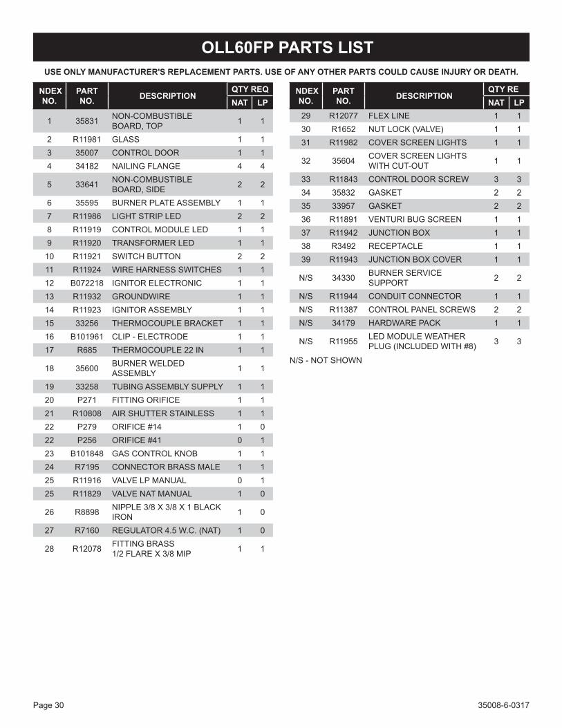
OLL60FP PARTS LISTUSE ONLY MANUFACTURER'S REPLACEMENT PARTS. USE OF ANY OTHER PARTS COULD CAUSE INJURY OR DEATH.
INDEX NO.
PART NO. DESCRIPTION
QTY REQNAT LP
1 35831 NON-COMBUSTIBLE BOARD, TOP 1 1
2 R11981 GLASS 1 13 35007 CONTROL DOOR 1 14 34182 NAILING FLANGE 4 4
5 33641 NON-COMBUSTIBLE BOARD, SIDE 2 2
6 35595 BURNER PLATE ASSEMBLY 1 17 R11986 LIGHT STRIP LED 2 28 R11919 CONTROL MODULE LED 1 19 R11920 TRANSFORMER LED 1 1
10 R11921 SWITCH BUTTON 2 211 R11924 WIRE HARNESS SWITCHES 1 112 B072218 IGNITOR ELECTRONIC 1 113 R11932 GROUNDWIRE 1 114 R11923 IGNITOR ASSEMBLY 1 115 33256 THERMOCOUPLE BRACKET 1 116 B101961 CLIP - ELECTRODE 1 117 R685 THERMOCOUPLE 22 IN 1 1
18 35600 BURNER WELDED ASSEMBLY 1 1
19 33258 TUBING ASSEMBLY SUPPLY 1 120 P271 FITTING ORIFICE 1 121 R10808 AIR SHUTTER STAINLESS 1 122 P279 ORIFICE #14 1 022 P256 ORIFICE #41 0 123 B101848 GAS CONTROL KNOB 1 124 R7195 CONNECTOR BRASS MALE 1 125 R11916 VALVE LP MANUAL 0 125 R11829 VALVE NAT MANUAL 1 0
26 R8898 NIPPLE 3/8 X 3/8 X 1 BLACK IRON 1 0
27 R7160 REGULATOR 4.5 W.C. (NAT) 1 0
28 R12078 FITTING BRASS 1/2 FLARE X 3/8 MIP 1 1
29 R12077 FLEX LINE 1 130 R1652 NUT LOCK (VALVE) 1 131 R11982 COVER SCREEN LIGHTS 1 1
32 35604 COVER SCREEN LIGHTS WITH CUT-OUT 1 1
33 R11843 CONTROL DOOR SCREW 3 334 35832 GASKET 2 235 33957 GASKET 2 236 R11891 VENTURI BUG SCREEN 1 137 R11942 JUNCTION BOX 1 138 R3492 RECEPTACLE 1 139 R11943 JUNCTION BOX COVER 1 1
N/S 34330 BURNER SERVICE SUPPORT 2 2
N/S R11944 CONDUIT CONNECTOR 1 1N/S R11387 CONTROL PANEL SCREWS 2 2N/S 34179 HARDWARE PACK 1 1
N/S R11955 LED MODULE WEATHER PLUG (INCLUDED WITH #8) 3 3
N/S - NOT SHOWN
INDEX NO.
PART NO. DESCRIPTION
QTY REQNAT LP

35008-6-0317 Page 31
OLL60FP PARTS VIEW
5
4
5
17 16
14
154
2726
2524
23
19
1010
12
2120
18
3
7
89
6
2829
22
30
32
31
11
1
3435
35
37
38
36
13
2
39
33
33

35008-6-0317Page 32
OLL60SP PARTS LISTUSE ONLY MANUFACTURER'S REPLACEMENT PARTS. USE OF ANY OTHER PARTS COULD CAUSE INJURY OR DEATH.
INDEX NO.
PART NO. DESCRIPTION
QTY REQNAT LP
1 35831 NONCOMBUSTIBLE BOARD, TOP 2 2
2 R11981 GLASS 2 23 35007 DOOR CONTROL 2 24 34182 NAILING FLANGE 8 8
5 33641 NONCOMBUSTIBLE BOARD, SIDE 4 4
6 35610 BURNER PLATE ASSEMBLY 1 1
7 R11986 LIGHT STRIP LED 2 28 R11919 CONTROL MODULE LED 1 19 R11920 TRANSFORMER LED 1 1
10 R11921 SWITCH BUTTON 2 2
11 R11924 WIRE HARNESS SWITCH-ES 1 1
12 B072218 Ignitor ELECTRONIC 1 113 R11932 GROUNDWIRE 1 114 R11923 Ignitor ASSEMBLY 1 1
15 33256 THERMOCOUPLE BRACKET 1 1
16 B101961 CLIP - ELECTRODE 1 117 R685 THERMOCOUPLE 22 IN 1 1
18 35600 BURNER WELDED ASSEMBLY 1 1
19 33258 TUBING ASSEMBLY SUPPLY 1 1
20 P271 FITTING ORIFICE 1 121 R10808 AIR SHUTTER STAINLESS 1 122 P279 ORIFICE #14 1 022 P256 ORIFICE #41 0 123 B101848 GAS CONTROL KNOB 1 1
24 R7195 BRASS CONNECTOR MALE 1 1
25 R11916 VALVE LP MANUAL 0 125 R11829 VALVE NAT MANUAL 1 0
26 R8898 NIPPLE 3/8 X 3/8 X 1 BLACK IRON 1 0
27 R7160 REGULATOR 4.5 W.C. (NAT) 1 0
28 R12078 FITTING BRASS 1/2 FLARE X 3/8 MIP 1 1
29 R12077 FLEX LINE 1 130 R1652 NUT LOCK (VALVE) 1 131 R11802 COVER SCREEN LIGHTS 1 1
32 34225 COVER SCREEN LIGHT WITH CUTOUT 1 1
33 R11843 CONTROL DOOR SCREW 6 634 33956 GASKET 2 235 33957 GASKET 2 236 R11891 VENTURI BUG SCREEN 1 137 R11942 JUNCTION BOX COVER 1 138 R3492 RECEPTICLE 1 139 R11943 JUNCTION BOX COVER 1 140 35611 PANEL, SEE-THRU 1 1
N/S 34330 BURNER SERVICE SUP-PORT 2 2
N/S R11944 CONDUIT CONNECTOR 1 1
N/S R11387 CONTROL PANEL SCREWS 2 2
N/S 34179 HARDWARE PACK 1 1
N/S R11955LED MODULE WEATHER PLUG (INCLUDED WITH #8)
3 3
N/S - NOT SHOWN
INDEX NO.
PART NO. DESCRIPTION
QTY REQNAT LP

35008-6-0317 Page 33
OLL60SP PARTS VIEW
2726
2524
23
19
1010
12
2120
2
3
5
7
89
4
2829
22
4
40
30
2
5
4
17 16
14
15
3
6
32
31
3435
3533
11
34
4
18
1
37
38
13
36
39
33

35008-6-0317Page 34
FIREPLACE SERVICE HISTORYDate Dealer Name Service Technician Name Service Performed/Notes

35008-6-0317 Page 35
WARRANTY TERMSEmpire Comfort Systems Inc. warranties this hearth product to be free from defects at the time of purchase and for the periodsspecifiedbelow.Hearthproductsmustbeinstalledbyaqualifiedtechnicianandmustbemaintainedandoperatedsafely,inaccordancewiththeinstructionsintheowner’smanual.Thiswarrantyappliestotheoriginalpurchaseronlyandisnottransferable.Allwarrantyrepairsmustbeaccomplishedbyaqualifiedgasappliancetechnician.
Limited Five-Year Parts Warranty – All Components (Except Remote Controls, Thermostats, Accessories and Replacement Parts) Shouldanypartfailbecauseofdefectiveworkmanshipormaterialwithinfiveyearsfromthedateofpurchase, EmpirewillrepairorreplaceatEmpire’soption.
Limited One-Year Parts Warranty – Remote Controls, Thermostats, Accessories, and Parts Shouldanyremotecontrol,thermostat,accessory,orotherpartfailbecauseofdefectiveworkmanshipwithinone yearfromthedateofpurchase,EmpirewillrepairorreplaceatEmpire’soption.
Duties of the Owner Theappliancemustbeinstalledbyaqualifiedinstallerandoperatedinaccordancewiththeinstructionsfurnished withtheappliance.Abillofsale,cancelledcheck,orpaymentrecordshouldbekepttoverifypurchasedateand establish warranty period. Ready access to the appliance for service.
What Is Not Covered Damages that might result from the use, misuse, or improper installation of this appliance. Travel, diagnostic costs and freight charges on warranted parts to and from the factory. Claimsthatdonotinvolvedefectiveworkmanshipormaterials. Unauthorized service or parts replacements. Removal and reinstallation cost. Inoperableduetoimproperorlackofmaintenance.
How To Get Service Tomakeaclaimunderthiswarranty,pleasehaveyourreceiptavailableandcontactyourinstallingdealer. Providethedealerwiththemodelnumber,serialnumber,typeofgas,andpurchaseverification.Theinstalling dealer is responsible for providing service and will contact the factory to initiate any warranted parts replacements. Empirewillmakereplacementpartsavailableatthefactory.Shippingexpensesarenotcovered. If, after contacting your Empire dealer, service received has not been satisfactory, contact: Consumer Relations Department, Empire Comfort Systems Inc., PO Box 529, Belleville, Illinois 62222, or send an e-mail to [email protected] with “Consumer Relations” in the subject line.
Your Rights Under State Law Thiswarrantygivesyouspecificlegalrights,andyoumayalsohaveotherrights,whichvaryfromstatetostate.

35008-6-0317Page 36
www.empirecomfort.com
Empire Comfort Systems Inc.Belleville, ILIf you have a general question about our products, please e-mail us at [email protected]. If you have a service or repair question, please contact your dealer.

AVERTISSEMENTS’il n’est pas installé, utilisé et entretenu selon les instructions du fabricant, ce produit pourrait vous exposer à des substances provenant de carburant ou de sa combustion qui pourrait entraîner la mort ou des maladies graves.
AVERTISSEMENTSi ces instructions ne sont pas respectées à la lettre, il peut se produire un incendie ou une explosion causant des dégâts matériels, des lésions corporelles ou pertes de vie humaine.
L’installation et l’entretien doivent être exécutés par un installateur qualifié, une agence de service ou par le fournisseur de gaz.
INSTRUCTIONS D’INSTALLATION ET MODE D’EMPLOI
INSTALLATEUR : Laisser ce manuel avec l’appareil.CONSOMMATEUR : Garder ce manuel pour référence ultérieure.
FOYER À GAZ LINÉAIRE EXTÉRIEURMODÈLE
OLL60FP12S(N,P)-1OLL60SP12S(N,P)-1
GAS-FIRED
! DANGER RISQUE DE MONOXIDE DE CARBONECet appareil peut produire du monoxyde de carbone qui n’a pas d’odeur.L’utiliser dans un endroit clos peut vous tuer.Ne jamais utiliser cet appareil dans un endroit clos comme une roulette, tente, voiture ou maison.
AVERTISSEMENTPour usage extérieur seulement.
AVERTISSEMENTSi vous sentez du gaz :1. Coupez le gaz à l’appareil.2. Éteignez toute flamme vive.3. Si l’odeur continue, éloignez-vous de
l’appareil et appelez immédiatement votre fournisseur de gaz ou les pompiers.
AVERTISSEMENTUne mauvaise installation ou altération, un mauvais ajustement, service ou entretien pourrait causer des blessures ou des dommages matériels. Lisez les instructions d’installation, d’utilisation et d’entretien soigneusement avant d’installer ou d’entretenir cet équipement.
AVERTISSEMENTNe pas entreposer et ne pas utiliser d’essence ni tout autre liquide aux vapeurs inflammables à proximité du présent appareil ou de tout autre appareil.Un cylindre GPL qui n’est pas connecté pour être utilisé ne devrait pas être rangé à proximité de cet appareil ou tout autre appareil.
Page 37

35008-6-0317Page 38
AVANT DE COMMENCER1. Lirelesinformationsrelativesàlasécuritéfigurantauxpages4à5.2. Quefaut-ilprendreencompteavantl’installation.VoirPage11.3. Ilfautprévoirunécoulementd’eau.Voirpage12.Plateau
d’écoulementenoption.4. Oùprévoyez-vousd’installerl’appareil?Voirpages11à13.5. Encadrerl’ouverture.Voirlespages8à10et14à15.6. Installer le foyer. Voir pages 14 à 16.7. Connecterl’électricité.Voirlespages16et26.8. Raccorder le gaz. Voir les pages 17 à 19.9. Installer le verre pilé. Voir page 22.10. Allumer le foyer et dépannage. Voir les pages 23 et 28.11. Montrer au propriétaire comment faire fonctionner le foyer.
Voir page 25. 12. Montreraupropriétairecommenteffectuerl’entretiendebase.
Voir page 27.
Outils requis :(1) - Clé Allen 1/8 po(2) - Clés ajustables avec jeu de 1 po pour connexion du gaz(2) - Clés de tuyau ajustables(1) - Tournevis Phillips
CONTENU DE L’EMBALLAGE
REPÈRE DESCRIPTIONQUANTITÉ FOURNIE
OLL60FP OLL60SP1 Panneau vitré 1 2
2 Panneau non combustible - dessus
1 2
3 Panneau non combustible - côté 2 4
4 Enveloppe 1 1
5 Brides de clouage 4 8
6 Prise 1 1
7 Couvercle 1 1
8 Raccord de conduit 1/2 po 1 1
9 Pile AA 1 1
10 Support de brûleur 2 2
Pour commander des pièces de rechange, voir la liste des pièces aux pages 30 à 33. Ne pas commander de piles, boulons, vis, rondelles ou écrous. Ce sont des articles de visserie standard pouvant être achetés dans toute quincaillerie ou tout magasin de bricolage.
1
6
2
3
5
7
4
8 9
10
CONTENU DU JEU DE QUINCAILLERIE
Nº 10-32 X 1/2 PO VIS À TÊTE HEXAGONALE(8 - OLL60FP12S(N,P))
(16 - OLL60SP12S(N,P))
VIS PHILLIPS AUTO-FOREUSE 1-1/4 PO(6 - OLL60FP12S(N,P))(12- OLL60SP12S(N,P))

35008-6-0317 Page 39
TABLE DES MATIÈRES
AVANT DE COMMENCER ............................................................................................................2TABLE DES MATIÈRES ................................................................................................................3INFORMATIONS DE SÉCURITÉ IMPORTANTES ........................................................................4INFORMATIONS DE SÉCURITÉ CONCERNANT LE GPL ..........................................................5INTRODUCTION ............................................................................................................................6SPÉCIFICATIONS .........................................................................................................................7ACCESSOIRES .............................................................................................................................7MATÉRIAUX COMBUSTIBLES ....................................................................................................8DÉGAGEMENTS ......................................................................................................................8 - 9DIMENSIONS DU FOYER ...........................................................................................................10PLANIFIER L’INSTALLATION .............................................................................................11 - 13INSTALLATION DU FOYER: - CADRAGE ET INSTALLATION .........................................................................................14 - 15
- ALIMENTATION ÉLECTRIQUE ...............................................................................................16
- ALIMENTATION EN GAZ ........................................................................................................17
- INFORMATION SUR LE CYLINDRE DE GPL ..................................................................18 - 19
- FINITIONS ........................................................................................................................20 - 22
INSTRUCTIONS D’ALLUMAGE .................................................................................................23CARACTÉRISTIQUES DE LA FLAMME DU BRÛLEUR PRINCIPAL .......................................24INSTRUCTIONS D’OPÉRATION / APPARENCE DE LA FLAMME ...........................................25CÂBLAGE ....................................................................................................................................26ENTRETIEN .................................................................................................................................27DÉPANNAGE ...............................................................................................................................28LISTE DES DISTRIBUTEURS DE PIÈCES PRINCIPAUX .........................................................29COMMENT COMMANDER DES PIÈCES DE RECHANGE .......................................................29OLL60FP LISTE DES PIÈCES ....................................................................................................30OLL60FP VUE DES PIÈCES .......................................................................................................31OLL60SP LISTE DES PIÈCES ....................................................................................................32OLL60SP VUE DES PIÈCES ......................................................................................................33MAINTENANCE HISTORIQUE DU FOYER ................................................................................34CONDITIONS DE LA GARANTIE ...............................................................................................35
SECTION PAGE

35008-6-0317Page 40
INFORMATIONS DE SÉCURITÉ IMPORTANTESDANGER : Indique une situation dangereuse qui, si elle
n’estpasévitée,causeralamortoudesblessuresgraves.
AVERTISSEMENT: Indique une situation potentiellement dangereuse qui, si elle n’est pas évitée, peut entraîner desblessures corporelles ou la mort.
ATTENTION : Indique une situation potentiellement dangereuse qui, si elle n’est pas évitée, peut entraîner desblessures corporelles mineures ou modérées.
AVIS:S’adresseàdespratiquesquinesontpasreliéesauxblessures corporelles.
AVERTISSEMENTNe pas placer des débris, bûches ou autres articles dans le foyer lors de l’opération.
AVERTISSEMENTToute modification aux contrôles peut être dangereuse. Une installation ou une utilisation incorrecte du foyer peut provoquer des blessures graves ou la mort par incendie, brûlure, explosion ou intoxication au monoxyde de carbone.
AVERTISSEMENTEffectuer régulièrement un contrôle visuel du brûleur. Nettoyer et remplacer les pièces endommagées.
DANGERLes enfants et les adultes doivent être avertis du danger des hautes températures de surface et être tenus à l’écart pour éviter de se brûler ou d’enflammer des vêtements.
DANGERLes jeunes enfants doivent être surveillés avec attention lorsqu’ils sont dans la même pièce que le foyer.
DANGERNe pas placer de vêtements ou autres matières inflammables sur ou à proximité du foyer.
DANGERMaintenir le voisinage du foyer dégagé et exempt de matières combustibles, essence et autres vapeurs et liquides inflammables.
• Installateur : Veuillez laisser ces instructions avec le propriétaire pour référence ultérieure
• Cette unité est conforme à ANSI Z21.97/CSA 2.41 pour les foyers à gaz extérieurs.
• L’installation et les réparations doivent être effectuées par un TECHNICIEN QUALIFIÉ. Le foyer doit être inspecté avant utilisation et au moins une fois par an par un technicien d’entretien qualifié. Un nettoyage plus fréquent peut être nécessaire en raison des insectes, accumulation de pollen, etc. Il est impératif que les compartiments de commande, les brûleurs et les passages de circulation d’air du foyer restent propres.
• Lors de la fabrication, usinage et expédition, certaines pièces du foyer sont traitées avec certaines huiles, certains films ou produits adhésifs. Ces produits ne sont pas nocifs, mais peuvent causer une fumée et des odeurs déplaisantes lorsqu’ils sont brûlés lors de l’opération initiale du foyer. C’est une situation normale et temporaire.
• Suivez tous les codes locaux au sujet de l’installation, la combustion et la ventilation d’air ou en l’absence de codes locaux, suivez le Code de gaz combustible national ANSI Z223.1 (Installation aux États-Unis), ou le code d’installation CAN/CGA-B149 (Installation canadienne).
• Inspectez le brûleur au moins une fois par année.• Maintenir la propreté du brûleur et du compartiment de
commande. • NE PAS utiliser le foyer si une quelconque partie a été immergée
dans l’eau. Appeler immédiatement un technicien d’entretien qualifié pour contrôler le foyer et remplacer toute pièce du système de commande et toute commande de gaz ayant été immergées.
• Toute protection ou tout dispositif de protection enlevé lors de l’entretien de l’appareil doit être remis en place avant d’utiliser l’appareil.

35008-6-0317 Page 41
INFORMATIONS DE SÉCURITÉ CONCERNANT LE GPLLe propane (GPL) est un gaz inflammable pouvant provoquer des incendies et des explosions. Dans son état naturel, le gaz propane est sans odeur et sans couleur. Vous pourriez ne pas connaître toutes les consignes de sécurité qui pourrait vous protéger vous et votre famille d’un accident. Veuillez les lire soin maintenant, puis révisez-les point par point avec les membres de votre famille. Un jour lorsqu’il n’y aura pas une minute à perdre, la sécurité de tout le monde dépendra du savoir-faire exact. Si après avoir lu les informations ci-dessous, vous croyez avoir besoin de plus d’information, veuillez contacter votre fournisseur de gaz.
DÉTECTION D’UNE ODEUR DE GAZ GPL
En cas de fuite de gaz, une odeur de gaz doit être perceptible parce que le GPL contient un odorisant. C’est votre signal d’agir immédiatement!
• Nepasactionnerdecommutateurélectrique,allumerd’allumette,ni utiliser le téléphone. Ne faites rien qui pourrait allumer le gaz.
• Fairesortirtoutlemondedubâtiment,duvéhicule,delacaravaneou de la zone. Faites ceci IMMÉDIATEMENT.
• Fermertouslesrobinetsderéservoiroudebouteilledegaz.
• LeGPLestpluslourdquel’airetpeuts’accumulerdansleszonesbasses telles que les sous-sols. Lorsque vous avez raison de douterd’unefuitedegaz,restezàl’écartdessous-solsettouteautrezonebasse.Restezàl’écartjusqu’àcequelespompiersles déclarent sécuritaires.
• Depuisunemaisonvoisine,téléphonezàunréparateurspécialiséenGPLetauxpompiers.Mêmesivousnesentezplusl’odeurdegaz,nerallumezpaslegaz.Nerentrezpasdanslebâtiment,levéhicule, la caravane ou la zone.
• Enfin, laisserleréparateuretlespompiersvérifierl’absencedegaz.Faites-lesaérerlazoneavantd’yrevenir.Lepersonnelderéparation formé au GPL doit réparer la fuite, puis contrôler et rallumer le foyer au gaz pour vous.
AUCUNE ODEUR DÉTECTÉE - AFFAIBLISSEMENT DE L’ODEURCertaines personnes ont l’odorat peu développé. Certaines personnes ne peuvent sentir l’odeur du produit chimique ajouté au gaz. Veiller à déterminer si on parvient à sentir l’odorisant dans le propane. Fumer peut diminuer votre aptitude à sentir. Être exposé à une odeur pour un certain temps peut affecter votre sensibilité ou aptitudeàdétectercetteodeur.Desfois,d’autresodeursdanslazonepeuventmasquer l’odeur dugaz. Lespersonnespourraient nepassentirl’odeurdugazouleursespritssontoccupésàd’autreschoses.Semettreàpenseràl’odeurdugazpeutrendrelatâcheplusfacile.
L’odorisant dans le GPL est incolore et peut s’estomper sous certaines circonstances. Par exemple, en cas de fuite souterraine, le passagedugazàtraverslesolpeutfiltrerl’odorisant.LesodorantsdugazGPLpeuvents’oxyder.Cetaffaiblissementpeutavoirlieulorsqu’ilyadelarouilleàl’intérieurduréservoiroudanslestuyauxdegazenacier.
L’odorisantprésentdanslegazéchappépeutêtreabsorbésuroudansles murs, la maçonnerie et autres matériaux ou tissus dans la pièce. Ceci retireunepartiedel’odorisantdugaz,réduisantl’intensitédesonodeur.
LeGPLpeuts’accumulerencouchesdanslesespacesclosetl’odeurpeutvarieraveclahauteur.Puisqu’ilestpluslourdquel’air,ilpourraitavoirplusd’odeurdanslesniveauxinférieurs.Soyeztoujourssensiblesà la moindre odeur de gaz. Si vous détectez une odeur, considérez-la commeunefuitesérieuse.Passezimmédiatementàl’actiontellequedécrite ci-dessus.
CERTAINS POINTS À GARDER À L’ESPRIT• Apprendre à reconnaître l’odeur duGPL. Votre fournisseur de
GPL local peut vous fournir une brochure «Gratter pour sentir». S’enservirpourapprendreàreconnaîtrel’odeurdupropane.Sile GPL utilisé semble avoir une odeur faible ou anormale, appeler le fournisseur de gaz.
• Nepasallumerdeveilleuse,effectuerd’entretienouajusterderéglagesurdesfoyersauGPLsionn’estpasqualifié.Sionestqualifié,bienpenseràl’odeurdeGPLavantetpendantl’allumagedeveilleuses,l’entretienouleréglagedesappareils.
• Lessous-solsetlesmaisonsnonaéréespeuventavoiruneodeurdemoisipouvantmasquerl’odeurduGPL.Nepastenterd’allumerdesveilleusesnid’effectuerd’entretienoude réglagedansunendroitoùlesconditionssonttellesquel’odeurpeutnepasêtredétectable en cas de fuite de GPL.
• L’affaiblissementdel’odeur,paroxydationsurlarouilleouadsorptionpar les parois de bouteilles ou de cuves neuves, est possible. Donc, les gens devraient être particulièrement vigilants et avertis lorsque de nouveaux réservoirs ou cylindres sont mis en service. L’affaiblissement de l’odeur peut se produire dans les cuvesneuves ou remises en service, si elles sont remplies et laissées trop longtemps avant le remplissage suivant. Les cylindres et les réservoirs qui ne sont plus en service pendant un certain temps vont développer une rouille intérieure qui cause un affaiblissement del’odeur.Sivouspensezquedetellesconditionsexistent,untestdereniflementdugazestrecommandé. Pour toute question concernant l’odeur du gaz, appeler le fournisseur de GPL. UN contrôle périodique de l’odeur du GLP est une bonne mesure de précaution dans toutes circonstances.
• Si,àtoutmoment,l’odeurdel’odorisantduGPLn’estpasperceptiblealorsqu’elledevrait l’être,présumerqu’ilyaunefuite.Prendreles mêmes mesures immédiates que celle préconisée plus haut lorsque le GPL odorisé est détecté.
• Encasd’épuisement totaldugaz (plusdepressiondevapeurdans le réservoir), fermer immédiatement le robinet du réservoir. Si la valve du réservoir est restée ouverte, le réservoir pourrait tirerdel’airautraversdesesouverturescommelesorificesdelaveilleuse. Dans ce cas, une rouille interne pourrait avoir lieu. Si la valve est laissée ouverte, traitez le conteneur en tant que nouveau réservoir.Pours’assurerqueleréservoiresttoujourssouspressionde vapeur, fermer le robinet ou refaire le plein du réservoir avant qu’ilsoitcomplètementvide.

35008-6-0317Page 42
SPÉCIFICATIONS DU PRODUIT
VERRE PILÉ DÉCORATIFJeux de verre pilé décoratif requis (10 pi² requis pour le brûleur et l’éclairage DEL)
Modèle DescriptionDG1CLF* Givré clair
Verre pilé décoratif (comme accent seulement)Modèle Description
DG1BKP* Noir poli
DG1BUC* Bleu clair
* Le verre pilé décoratif givré clair est requis. Les gouttelettes décoratives en verre ne peuvent être substituées au verre pilé. Un sac de verre pilécouvre1pi².Suffisammentdeverrepilépourcouvrir10pi²estrequis.Lescouleursduverrepeuventêtremélangées.10sacssontlaquantité maximale de verre pilé décoratif permise. Le verre pilé transparent et translucide permet aux DEL de mieux briller à travers.
Les gouttes et les gouttelettes décoratives en verre (peuvent être utilisées en plus du verre pilé)Modèle Description
DG1NXS 1 po Gouttes décoratives en verre - Onyx solide
DG1RYC 1 po Gouttes décoratives en verre - Ruby clair
DG1TZC 1 po Gouttes décoratives en verre - Topaze clair
DG1AB 1/2 po Gouttelettes décoratives en verre - Aqua bleu
DG1GC 1/2 po Gouttelettes décoratives en verre - Glacier Ice
DG1SL 1/2 po Gouttelettes décoratives en verre - Sangria Luster
Remarque : Les gouttelettes décoratives en verre peuvent être ajoutées sur le dessus du verre pilé pour enjoliver. Les gouttelettes décorativesenverredoiventêtreplacéessurlaflammedubrûleur.Vousreporteràl’installationdeverrepilé,page22.Nepasajouterplusd’unsacdegouttelettesdécorativesenverre.
AccessoiresModèle Description
DT48LSS Plateaud’écoulementenacierinoxydable–(Pourlesfoyers48poet60po)
WD60LSS Porte en acier inoxydable – 60 po (commander deux pour les foyers ouverts 2 faces)
WG60LT1 Verredéflecteurpourlesendroitsventeux–60po(commanderdeuxpourlesfoyersouverts2 faces)
35829 Trousse de conversion du gaz naturel au GPL
35830 Trousse de conversion GPL à gaz naturel
ACCESSOIRES
Modèle Gaz Type de vanne Orifice BTUH Débit Max. BTUH Débit Min.OLL60FP12L NAT MANUEL Nº 14 65 000 39 000
OLL60FP12L PL MANUEL Nº 41 65 000 37 000
OLL60SP12L NAT MANUEL Nº 14 65 000 39 000
OLL60SP12L PL MANUEL Nº 41 65 000 37 000
Gaz naturel Gaz propaneRéglage de pression du collecteur 4-1/2 po CE 11 po CE
Pressiondegazd’entrée Max. 7 po CE 11 po CE
Réglaged’obturateurd’air 1/16 po ouvert Totalement ouvert

35008-6-0317 Page 43
INTRODUCTIONLesâtresdevraientêtreenpenteensenscontrairedel’avantdufoyeretqu’ildescendede0,31à0,64cm(1/8à1/4po)parpied.Desbandesmétalliques de refuge doivent se trouver au-dessus de tout matériau combustibledel’âtreutiliséspourlagestiond’humidité.
Lorsdel’achatd’uneboîteàfeu,nousrecommandonsd’acheteraussiunehoussepourprotégerl’appareilcontrel’humidité.Nejamaisposerunbrûleurdansunendroitoùl’humiditénepeutpass’évacuerfacilement.Nousrecommandonsd’utiliseruneprotectioncontrelesintempériespourprotégerlebrûleurdel’humidité.
Service d’installation qualifiéLaposeetleremplacementdeconduitesdegaz,d’appareilsalimentésau gaz ou d’accessoires et la réparation et l’entretien du matérieldoiventêtreconfiésàunservicequalifié.Leterme«servicequalifié»faitréférenceàtoutepersonne,firme,sociétéouentreprisequi,soitenpersonnesoitpar l’intermédiaired’un représentant,estengagéedans et responsable de (a) la pose ou le remplacement de conduites degazou(b)leraccordement,l’installation,laréparationoul’entretiende matériel, qui est expérimentée dans ce domaine, familiarisée avec touteslesmesuresdeprécautionrequisesets’estconforméeàtoutesles exigences réglementaires en vigueur.
Codes locaux• Lorsquelefoyerestconnectéàunsystèmedetuyauteriefixe,
l’installationdoitseconformeraveclescodeslocaux,ouenl’absencedecodeslocaux,avecleCode de gaz combustible national ANSI Z223.1/NFPA 54, ou le Code de gaz combustible international.
• Le foyer, lors de son installation, doit être électriquement relié à la terre en conformité avec la réglementation locale ou, en l’absencederéglementationlocale,avecleCode électrique national, ANSI/NFPA 70, si applicable.
CommonwealthduMassachusetts:L’installationdoitêtreeffectuéepar un plombier ou un installateur-chauffagiste agréé dans le Commonwealth du Massachusetts.
L’installationdoitêtreconformeaveclescodeslocauxou,dansl’absencede codes locaux, avec le Code de gaz combustible national ANSI Z223.1.*
*Disponible auprès de l’American National Standards Institute, Inc. 1430 Broadway, New York, N.Y. 10018.
Hautes altitudesAuxaltitudessupérieuresà610m(2000pieds),lesvaleursd’entréedoivent être réduites de 4% pour chaque portion de 305 m (1 000 pieds) au-dessus de la mer. Contactez le fabricant ou votre société de gaz avantdechangerlatailledel’injecteur/orifice.
Installations pour le gaz de tête de puitsCertaines installations au gaz naturel de type «tête de puits». Ceci peut affecterleBTUdesortiedel’unité.Contactezlasociétédegazpourobtenir la valeur de chauffage. Contactez le fabricant ou votre société degazavantdechangerlatailledel’injecteur/orifice.
Instructions à l’installateur1. L’installateur doit laisser lemanuel d’instructions au propriétaire
après la pose.
2. L’installateurdoitdemanderaupropriétairederempliretposterlacarted’enregistrementfournieaveclefoyeroudes’enregistrerenligne sous www.empirecomfort.com.
3. L’installateurdoitmontreraupropriétairecommentdémarreretfairefonctionner le foyer extérieur.
Toujours s’informer auprès du Service de la construction local desréglementations,codesouordonnancess’appliquantà laposed’unfoyer à gaz extérieur.
AVERTISSEMENTPour éviter des blessures et des dommages au foyer ou à la zone environnante, ne pas brûler du bois ou autres combustibles solides dans ce foyer.
AVERTISSEMENTTOUTE MODIFICATION DE CE FOYER OU DE SES COMMANDES PEUT ÊTRE DANGEREUSE. Une installation ou une utilisation incorrecte du foyer peut provoquer des blessures graves ou la mort par incendie, brûlure, explosion ou intoxication au monoxyde de carbone.
LeconceptdecettesérieestcertifiéconformémentauxnormesANSI Z21.97/CSA 2.41 pour foyers au gaz extérieur et doit être installé conformément à ces instructions.
Toute modification de la configuration d’origine, installation autre que celles présentées dans ces instructions ou utilisation d’un type de gaz non spécifié sur la plaque signalétique relève de la responsabilité de la personne ou de la société effectuant la modification.Système de sécurité à valve manuelleLorsquelebrûleurs’allume,unethermopiledétecteunsignal(courantélectrique) qui active un aimant dans la vanne de gaz. Après 30 à 60 secondes,onpeutrelâcherleboutondecommande.Silathermopilenedétectepaslaflamme,legazserafermé.
ImportantToute correspondance doit comporter le numéro de modèle complet, le numéro de série et le type de gaz.
Résistance à l’humiditéCefoyerextérieurdéverseradefaiblesquantitésd’eau,maisn’estpasétanche.L’eauetlavapeurd’eauencondensationpourraiententrerdans le caniveau sous certaines conditions.
Le foyer ne performera pas en tant que mur extérieur. La pénétration de l’humiditédoitêtreconsidéréepourlesconstructionsquiplacentlefoyerdansdesmursdestructuresousurdessurfacessensiblesàl’humidité.
Lorsqu’ilestinstallésurdesmursextérieurs:EmpireComfortSystemsrecommandeque lecaniveaudufoyersoitconstruità l’extérieurdel’enveloppe d’intempérie. À l’endroit où la plateforme rencontre lemur, utilisez une bande de solins similaire à celle nécessaire pour les terrassesattachées.Lesplateformesdecaniveaux,ycomprislesâtres,devraient être en pente à partir de la structure à 0,64 cm (1/4 po) par pieds. Le foyer peut être calé pour le mettre à niveau.
Lorsqu’ilestinstallésurdessurfacesoùdel’eaupourraitsedéposerou causer des dommages : Empire Comfort Systems recommande une pente de 0,31 à 0,64 cm (1/8 po à 1/4 po) par pied vers le drain suggéré. Le foyer peut être calé pour le mettre à niveau.

35008-6-0317Page 44
DÉGAGEMENTS
D
C
E
B
A
F
Repère Description
Dimension depuis
l’ouverture du foyer (en pouces)
A Depuis le sol ou autre surface combustible 10-1/4*
B Depuis les parois 6
C Du plafond (minimum) 24
D Largeurdel’alcôve(minimum) 72
E Profondeurdel’alcôve(maximum) 24
F Hauteur de plafond (minimum) 90
*Remarque : la dimension A comprend 3-1/2 po sous le foyer pour supporterlecadrageetl’installationduplateaud’écoulement.
Figure 3 – dégagements pour l’alcôve du foyer
Dégagements minimaux pour mur et plafondDégagementspourparois:L’espacemententrel’intérieurdufoyerettout type de mur combustible ne peut être inférieur à 15,25 cm (6 po).Espacements du plafond : La hauteur du plafond ne devrait pas être inférieure à 61 cm (24 po) à partir du capot.Dégagementdumanteau:Siunâtreinflammableestinstallé,ildoitse conformer aux exigences de dégagement décrites dans la figure 2.
COMBUSTIBLES PERMIS
MANTEAU
12 po10 po
8 po
4 po
6 po
2 po
12 po
14-3/8 po16-13/16 po
19-3/16 po
21-5/8 po
24 po
Figure 2 – dégagements pour manteau de foyer
Nepasattacherdematériauxcombustiblesàl’âtredevotrefoyer.Ceciestunrisqued’incendie.
Figure 1
MATÉRIAUX COMBUSTIBLESNe jamais poser ni accrocher de cartes de vœux, bas ou ornements de quelle que nature que ce soit sur le foyer. Ceci st un appareil de chauffage.Lefluxdechaleurpeutenflammercesmatièrescombustibles.Remarque : ceci concerne les deux côtés des foyers ouverts à deux
faces.
Considérations pour télévisionL’installationd’unetélévisionau-dessusd’unfoyerestdevenuedeplusenpluspopulaire;cependant,l’espaceau-dessusdetoutfoyerdevientchaud et la plupart des fabricants de télévision ne recommandent pas d’installerleursproduitsàproximitéd’unesourcedechaleur.Si vous installez une télévision au-dessus de ce foyer, soyez avisé que EmpireComfortSystemsn’accepteaucuneresponsabilitéencasdedommageoublessures.Suivrelesdirectivesd’installationdufabricantde télévision ainsi que toutes recommandations se rapportant à la proximité avec les sources de chaleur.Si vous avez une télévision au-dessus du voyer, éteignez le foyer et laissez-le complètement refroidir avant de faire l’entretien ou detoucher les boutons de la télévision.
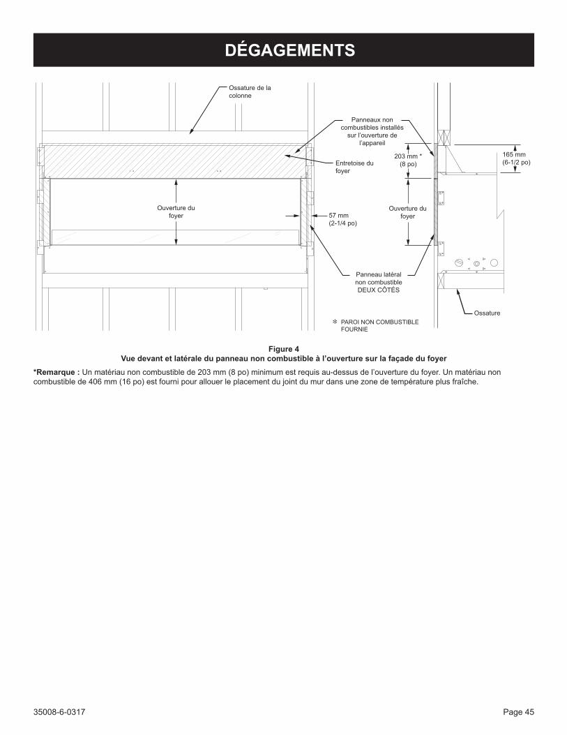
35008-6-0317 Page 45
Figure 4 Vue devant et latérale du panneau non combustible à l’ouverture sur la façade du foyer
*Remarque : Unmatériaunoncombustiblede203mm(8po)minimumestrequisau-dessusdel’ouverturedufoyer.Unmatériaunoncombustiblede406mm(16po)estfournipourallouerleplacementdujointdumurdansunezonedetempératureplusfraîche.
165 mm (6-1/2 po)
Ossature de la colonne
Ouverture du foyer
Ouverture du foyer
Entretoise du foyer
Panneaux non combustibles installés
sur l’ouverture de l’appareil
Panneau latéral non combustible DEUX CÔTÉS
57 mm (2-1/4 po)
203 mm *(8 po)
PAROI NON COMBUSTIBLE FOURNIE
Ossature
DÉGAGEMENTS
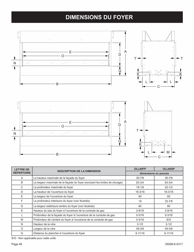
35008-6-0317Page 46
DIMENSIONS DU FOYER
LETTRE DE RÉPERTOIRE DESCRIPTION DE LA DIMENSION
OLL60FP OLL60SPdimensions en pouces
A La hauteur maximale de la façade du foyer 30-7/8 30-7/8
B La largeur maximale de la façade du foyer (excluant les brides de clouage) 63-3/4 63-3/4
C La profondeur maximale du foyer 19-1/8 22-1/2
D Lahauteurdel’ouverturedufoyer 16-3/16 16-3/16
E Lalargeurdel’ouverturedufoyer 60 60
F La profondeur intérieure du foyer (non illustrée) 19 23-7/8
G La largeur extérieure arrière du foyer (non illustrée) 60 60
K Hauteurdubasdufoyeràl’ouverturedelaconduitedegaz 2-9/16 2-9/16
L Profondeurdelafaçadedufoyeràl’ouverturedelaconduitedegaz 5-3/16 5-3/16
M Profondeurdel’arrièredufoyeràl’ouverturedelaconduitedegaz 5-3/16 S/O
N Hauteur de la vitre 3-1/2 3-1/2
O Largeur de la vitre 59-3/8 59-3/8
Q Distanceduplancheràl’ouverturedufoyer 6-11/16 6-11/16
S/O - Non applicable pour cette unité.
KQ
D
K
BC
L L
N
E
O
A
KQ
D
C
L
A
B
N
E
O
T T
T
M

35008-6-0317 Page 47
Ce dont il faut tenir compte avant l’installation1. Vérifierqueletypedufoyeraugazetletyped’alimentationen
gaz sont les mêmes.2. Trouverunendroitoùlescombustiblesnerisquentpasd’interférer.3. Une prise avec disjoncteur de fuite de terre 120 volts sera
nécessaire pour les témoins DEL4. Choisirunendroitpourlavalved’arrêtdugaz.5. Vérifierquelaventilationrespectelesexigencesminimales.6. Sens du vent et de la pluie.7. Écoulement sous le foyer.8. Bacd’écoulementetcontre-porte.9. Accessoires en verre.
Lorsde laplanificationde l’installationdu foyer,déterminer l’endroitoùl’unitéserainstalléetsidesaccessoiresfacultatifssontdésirés.Latuyauteried’alimentationengazdevraitaussiêtreplanifiéeàcepoint.Lefoyerpeutêtreposésurl’unedessurfacessuivantes:1. Uneossaturerelevéedematérielcombustibleafinquelecontact
se fasse sur les quatre bords du périmètre inférieur du foyer à au moins 89 mm (3-1/2 po) au-dessus du sol.
2. Les quatre coins du foyer doivent être en contact avec les quatre bordspérimètreaubasde l’unitéàaumoins89mm(3-1/2po)au-dessusdusol.Vérifierlesexigencesenmatièred’allocation.
Àcepoint,vousdevriezavoirdécidéquelscomposantsàajouteràvotreinstallation,etl’emplacementdufoyer.Sicen’estpasdéjàfait,arrêtezetconsultezvotreconcessionnaireaveccetteplanification.
AVERTISSEMENTCe foyer est conçu pour être installé sur une terrasse ou dans votre jardin. Ce foyer ne peut être utilisé qu’à l’extérieur dans un endroit bien aéré et ne doit PAS être utilisé dans un bâtiment, garage ou tout autre endroit fermé. Ce foyer ne peut être installé avec une ouvertureàl’intérieurd’unerésidence.
AVIS : Ce foyer n’est PAS équipé d’un pilote détecteur d’appauvrissement de l’oxygène (ODS).
L’installationdecefoyerpeutêtredansunendroit«ouvert»,toutefoisilestrecommandéd’installercefoyerdansunendroitàl’abridesventsdirects.Leventdirectrendralaflammeinstableetpourraitéteindrelebrûleur.Laflammeerratiquepourraitcauserunesuienoireexcessive.Ces situations sont gênantes plutôt que des problèmes de sécurité. Éviterlesendroitsoùilyaunrisqued’humiditéoud’eaucouranteàproximité ou sur le foyer.Une installation typique pourrait comprendre une terrasse couverte, unevérandaouverte,unbelvédèreoulemurextérieurd’unemaison.• Aire de véranda minimum – 8,91 m (96 pieds) carrés• Hauteur de plafond minimum – 229 cm (90 pouces)
Les témoinsDELont besoin d’une prise avec disjoncteur de terre120 volts sur le côté valve du foyer. La prise avec disjoncteur de terre serainstalléeàl’extérieurdufoyer.Uneboîtedejonctionestlivréeàl’intérieurdufoyerafind’offrirunemplacementpourbrancherlesDEL.
Exigences pour boîtier de foyer extérieurNepas installer le foyer tant que toutes lesmesures n’ont pasétéeffectuéesàl’égarddelacombustionetl’airdeventilation.Veuillezlireles directives écrites livrées avec le foyer pour obtenir des informations concernant lacombustionet l’airdeventilation.Fautededirectives,veuillez consulter le code national en matière de gaz combustible, ANSI Z223.1/NFPA54, air pour combustion et ventilation ou les codes locaux en vigueur.
L’installation dans un boîtier partiel doit être conformeà l’une desconditions suivantes :• Avec des parois sur tous les côtés, mais aucun couvert aérien.
Voir figure 5.
Figure 5
• Avecunboîtierpartielquicomprenduncouvertaérien,maispasplus de deux parois latérales. Ces parois latérales peuvent être parallèles, comme dans un passage couvert ou à angles droits sur chaque côté. Voir figure 6.
Figure 6
PLANIFIER L’INSTALLATION

35008-6-0317Page 48
PLANIFIER L’INSTALLATION• Àl’intérieurd’uneenceintepartiellecomprenantuncouvercle
sur le dessus et trois parois latérales, pourvu que 30 pour cent ou plus de la périphérie horizontale (périmètre des murs etducôtéouvert)del’enceintesoitouverteenpermanence.Voir la Figure 7.
Figure 7
Sil’installations’effectuedansunporcheavecmoustiquaire,l’espaceouvertdoitêtreajusté(augmenté)de30pourcent(espaceouvertajusté=30%/%del’aireouvertedelamousti-quaire). « Par exemple, si vous utilisez une moustiquaire avec 66 %d’aireouverte,l’espaceouvertminimumdevotrebâtimentdoitêtre égal à 46 % de la périphérie. Si vous avez un porche (recou-vert) avec moustiquaire comportant deux parois latérales de 16 pi chacune, une paroi contre la maison de 20 pi et un côté ouvert de 20 pi, le périmètre totaliserait 72 pi. Vous auriez donc besoin de 33 pi de périmètre ouvert (72 pi x 46 % = 33 pi). »
(Adressez-vous au fabricant ou revendeur de moustiquaire pour déterminer l’aire ouverte de vos moustiquaires).
AVIS : Avis de non-responsabilité Soffite vinyle, plafond vinyle, surplomb vinyleLesdégagementssontjusqu’aumatériaurésistantàlachaleur(parex.bois,métal).Cecin’inclutpaslevinyle.EmpireComfortSystemsInc. ne sera pas tenu responsable des dommages causés par la chaleur à cause des terminaisons sous des surplombs en vinyle, desplafonsenvinyleoudessoffitesenvinyleventilés/nonventilés.
AVERTISSEMENTUne mauvaise installation ou altération, un mauvais ajustement, service ou entretien pourrait causer des dommages matériels, des blessures, voiremême lamort.L’installationet l’entretiendoiventêtreexécutésparuninstallateurqualifié,uneagencedeserviceoupar le fournisseur de gaz.
Raccordement de conduite de gazLe foyer est conçu pour accepter une conduite de gaz de 1/2 po. Faites installerlaconduiteparunepersonnequalifiéeselontouslescodesenbâtiment.Consulterlescodesenbâtimentlocauxpourinstalleruneconduite d’alimentation degazadéquate pour un raccordement de1/2poàl’appareil.L’étatduMassachusettsprévoitqu’unconnecteurdefoyerflexiblenedoitpasdépasser91cm(troispieds)delong.Unraccordementdeconduiteflexibleauxvalvesestfourni.Le robinet d’arrêt du gaz doit se trouver à l’extérieur de l’appareil à un endroit accessible.
Vérifierletypedegazsurl’étiquettedevaleursnominalesàl’arrièredelaportedecontrôle.Silegazindiquésurl’étiquettedevaleursnominalessur le panneau de commande ne correspond pas au gaz alimenté, NE PASINSTALLER.S’informerauprèsdufournisseurpourunmodèlequiconvientoud’unetroussedeconversion.ToujoursutiliserunrégulateurexternepourtouslesfoyersauGPLafinde réduire la pression au réservoir à un maximum de 13 po CE.
AVERTISSEMENTUn raccordement direct à un réservoir GLP non régulé peut causer une explosion.
AVERTISSEMENTRisque d’incendie, d’explosion ou d’asphyxie. Veiller à ce qu’iln’y ait pas de flammeni d’étincelle pouvant allumer à proximitéde l’installation.Cecicomprenddescigarettesoudes téléphonescellulaires.
Faireuntestd’étanchéitédetouslesraccordementsavecunesolutiond’eauetdesavon.Une formationdebulles indiqueune fuite.Faireattention pour éviter les brûlures.
CONDUITE FLEXIBLE
VANNE D’ARRÊT DE
GAZ (ROBINET)
PORTE D’ACCÈS
ALIMENTATION EN GAZ
Figure 8
Exigence en matière d’écoulement d’eauIl faut prévoir d’éloigner de l’appareil tout écoulement d’eau. Il estpossibled’acheterunbacd’écoulementenoptionchezvotredétaillantEmpirequis’installesouslefoyer.Siunbacd’écoulementenoptionestinstallé,ilfautlefaireavantd’installerlefoyer.Pourobtenirdeplusamples informations, veuillez consulter les directives d’installationfourniesaveclebacd’écoulement.Sicebacn’estpasutilisé,ilfautinstallerd’autreévacuationd’eau.

35008-6-0317 Page 49
Considérations électriques
ATTENTIONTouslescâblagesdoiventêtreeffectuésparunélectricienqualifiéetêtreconformesàtouslescodesdubâtimentlocaux,municipauxetprovinciauxenvigueur.Avantd’effectuerleraccordementélectrique,s’assurerquel’alimentationélectriqueprincipaleestdébranchée.Lefoyer, lors de son installation, doit être électriquement relié à la terre en conformité avec la réglementation locale ou, en l’absencederéglementation locale, avec le code électrique national, ANSI/NFPA 70, si une source électrique externe est utilisée.
Uneboîtedejonctionestposéed’usinesurlecôtéinférieurdroitdufoyer.Laboîtedejonctionetlecâblagepeuventêtreinstallésdel’autrecôtédufoyersidésiré.Lecâblageàlaboîtedejonctiondoitavoirunegaine métallique ou être dans un conduit approuvé pour une utilisation extérieure. Connecter le câblage à une prise avec disjoncteur à laterre externe installée à proximité du foyer. Voir figure 9.
Prise avec disjoncteur à la terre
COMMANDES
Figure 9
PLANIFIER L’INSTALLATION

35008-6-0317Page 50
ENCADREMENT ET INSTALLATION DE FOYER
Déballage du foyerAprèsavoirenlevélaboîteencarton,retirerlesvisquiretiennentlespoteaux de coin et le contreplaqué au foyer. Jeter les poteaux de coin et le contreplaqué.Le panneau non combustible est sous le foyer sur la palette. Retirer toute pellicule protectrice du foyer et tous les composants (brides de clouage, entretoises, etc.).
OssatureL’ossaturedufoyerdoitêtreconstruiteavantlamiseenplacedufoyer.L’ossaturedufoyerpeutêtrefabriquéeenmontantsde5,1cmx122cm(2pox4po).Leslinteauxd’ossaturedoiventreposersurlesentretoisesdufoyer.Voirlesdimensionsminimalesd’ossatureàlafigure 11.
ATTENTIONMesurerlesdimensionsdufoyeretvérifierl’ossatureprévueetlesrevêtements de mur avant de commencer la construction.
La dimension A de l’ossature comprend un dégagement de 16 ½ po pour les entretoises sur le dessus du foyer. Après avoir installé la chambre de combustion dans l’ossature, le mur fini doit couvrir cette ouverture de 16 ½ po au-dessus de la chambre de combustion.
B
C
A
ÉCOULEMENT D’EAU DE CE
CÔTÉ
MAINTENIR LA ZONE OUVERTE
POUR L’ÉCOULEMENT
DIMENSIONS DE L’INSERTION (en pouces)OLL60FP OLL60SP
Hauteur A 31 31
Largeur B 64 64
Profondeur C 19-1/4 22-1/2
Figure 11 – Ossature du foyerAvantdeterminer l’ossatureetd’installer lefoyer,fourniruncheminpouréloignerl’écoulementd’eaudufoyer.
Déterminersilebacd’écoulementenoptionserautilisé.Vousreporteràlapage12.Silebacd’écoulementestinstallé,suivrelesdirectivesfourniesaveccedernierpourl’installeràcetteétape.
Installation1. Choisirunemplacementpourl’installation.2. Construirel’ossaturepourlefoyer.Vousreporterauxdimensions
del’ossatureàlafigure11.Lesdégagementssontindiquésauxpages 8 et 9.
3. Repérer les brides de clouage dans l’enveloppe d’installationet les fixer aux côtés du foyer avec deux vis hexagonalesn° 10 – 32 x 1/2.
Figure 12 - Position de la bride de clouage4. Plier lespattesdebridedeclouageàanglesdroits jusqu’àce
qu’ellessoientalignéesaveclafacadedufoyer.Pour les foyers deux faces seulement : Plier les pattes sur un côté du foyer seulement. Plier les pattes sur la bride supérieure de la façade opporés à angles droits pour permettre aux pattes dedégagerl’ossaturelorsduglissementdufoyerenplace.Voir figure 13.
5. Soulever le foyer et installer dans l’ossature. Glisser le foyerjusqu’àcequelesbridesdeclouagerencontrentl’ossature.Fixerlefoyeràl’ossatureavecunevisàcloisonsèchen°8x1.Pourles foyersàdeux faces,plier l’arrièredesbridesdeclouageàanglesdroitssortietfixeravecunevisàcloisonsèchen°8x1.
Figure 13
CADRAGE ET INSTALLATION

35008-6-0317 Page 51
ENCADREMENT ET INSTALLATION DE FOYER
6. Fixer labridedeclouageauxgoujonsd’ossaturedecôtéavecquatre vis à cloison sèche n° 8 x 1
7. Pour raccorder la conduite de gaz et installer la connexion électrique, le brûleur doit être incliné vers le haut du foyer. a Retirer la porte de contrôle en ouvrant la porte, en retirant
l’axe d’articulation central, et en la soulevant vers le hautpour désengager les fentes sur les extrémités de la porte danslesaxesd’articulation.
b. Retirerlesdeuxboulonsd’articulationetlesrondellesdelaporte de contrôle. Voir figure 14.
PORTE DE CONTRÔLE
BOUTON DE COMMANDE
Figure 14
c. Retirer les deux vis des coins avant du panneau de contrôle avecuntournevisPhillips.Voirfigure15.
ENSEMBLE BRÛLEUR
Figure 15
d. Soulever le devant de l’ensemble du brûleur etincliner vers le haut et l’arrière du foyer. Récupérerles deux supports à l’intérieur du foyer et placer dechaque côté contre les coins avant au bas de l’armoireet sous les coins avant du panneau de contrôle. REMARQUE : Être prudent lors du soulèvement du brûleur pouréviterd’égratignerl’intérieurinoxydabledufoyer.
SUPPORT AUX QUATRE COINS
Figure 16
8. Installer les alimentations de gaz et électrique au foyer. Vous reporteràlapage17pourlesexigencesenmatièred’alimentationde gaz. Pour faciliter l’installation, les alimentations de gaz etélectrique se trouvent sur le côté valve du foyer. Les deux peuvent êtrerelocaliséessurl’autrecôtédufoyer.
CADRAGE ET INSTALLATION
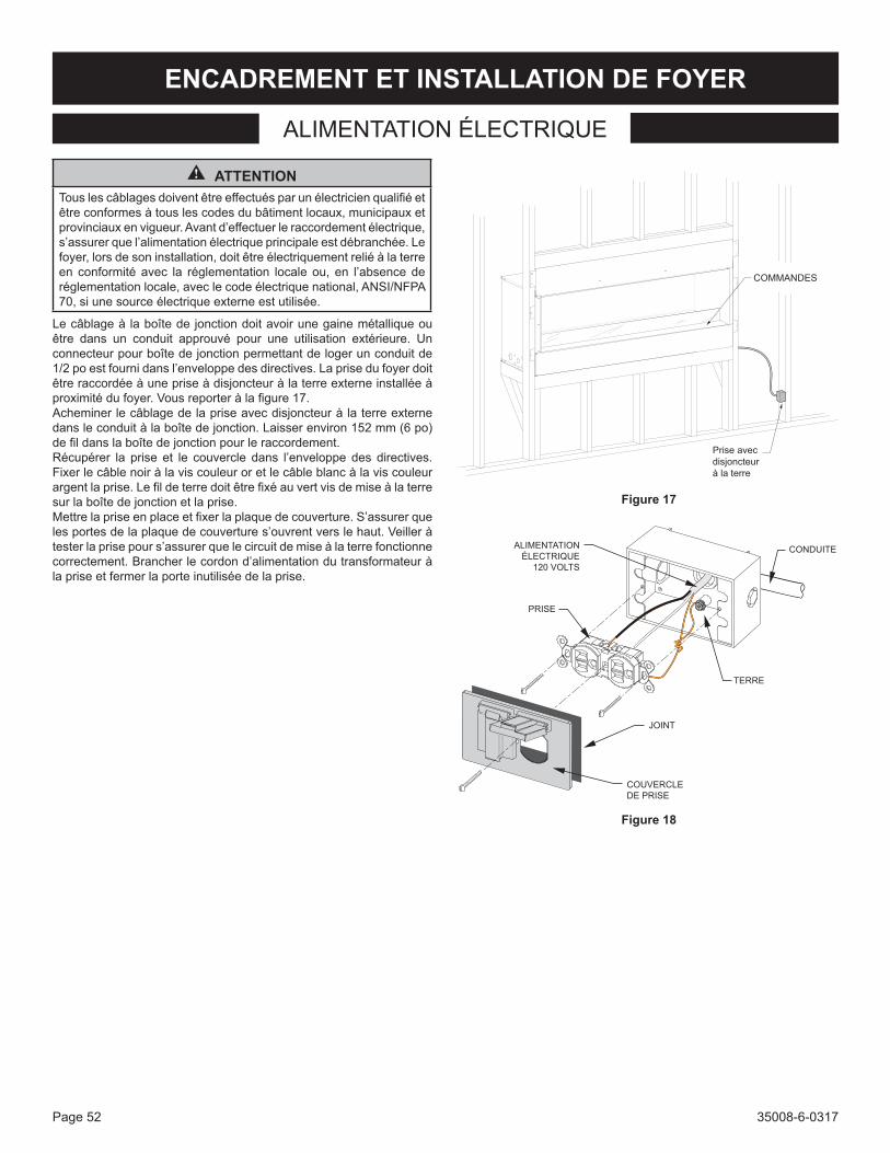
35008-6-0317Page 52
ENCADREMENT ET INSTALLATION DE FOYER
Prise avec disjoncteur à la terre
COMMANDES
Figure 17
ALIMENTATION ÉLECTRIQUE
120 VOLTS
PRISE
CONDUITE
TERRE
JOINT
COUVERCLE DE PRISE
Figure 18
ALIMENTATION ÉLECTRIQUE
ATTENTIONTouslescâblagesdoiventêtreeffectuésparunélectricienqualifiéetêtreconformesàtouslescodesdubâtimentlocaux,municipauxetprovinciauxenvigueur.Avantd’effectuerleraccordementélectrique,s’assurerquel’alimentationélectriqueprincipaleestdébranchée.Lefoyer, lors de son installation, doit être électriquement relié à la terre en conformité avec la réglementation locale ou, en l’absencederéglementation locale, avec le code électrique national, ANSI/NFPA 70, si une source électrique externe est utilisée.
Lecâblageàlaboîtedejonctiondoitavoirunegainemétalliqueouêtre dans un conduit approuvé pour une utilisation extérieure. Un connecteurpourboîtedejonctionpermettantdelogerunconduitde1/2poestfournidansl’enveloppedesdirectives.Laprisedufoyerdoitêtre raccordée à une prise à disjoncteur à la terre externe installée à proximitédufoyer.Vousreporteràlafigure17.Acheminerlecâblagedelapriseavecdisjoncteuràlaterreexternedansleconduitàlaboîtedejonction.Laisserenviron152mm(6po)defildanslaboîtedejonctionpourleraccordement.Récupérer la prise et le couvercle dans l’enveloppe des directives.Fixerlecâblenoiràlaviscouleuroretlecâbleblancàlaviscouleurargentlaprise.Lefildeterredoitêtrefixéauvertvisdemiseàlaterresurlaboîtedejonctionetlaprise.Mettrelapriseenplaceetfixerlaplaquedecouverture.S’assurerquelesportesdelaplaquedecouvertures’ouvrentverslehaut.Veilleràtesterlaprisepours’assurerquelecircuitdemiseàlaterrefonctionnecorrectement.Brancherlecordond’alimentationdutransformateuràla prise et fermer la porte inutilisée de la prise.

35008-6-0317 Page 53
ENCADREMENT ET INSTALLATION DE FOYER
• Les combustibles solides ne doivent pas être brûlés dans ce foyer.
• Lapressiond’alimentationengazmaximumestde11popourleGPL et 10,5 po pour le gaz naturel.
• Pourlesfoyerspoursystèmedetuyauteriedecombustiblefixeetéquipésd’unrégulateurdepressionàgazpourfoyer,lapressiond’admissiondanslacolonned’eauestde:11popourleGPLet4,5 po NAT.
• Pour les foyers pour système de tuyauterie de combustible fixe et équipés d’un régulateur de pression à gaz pour foyer,l’appareiletsesvalvesdesectionnementindividuelsdoiventêtredéconnectésdedusystèmed’alimentationdegaz lorsde touttest de pression de ce système à des pressions supérieures à 3,5kPa(1/2psi).Lefoyerdoitêtre isoléducircuitd’arrivéedegazparlafermeturedesavanned’arrêtindividuelleduranttoutessaidepressionducircuitd’alimentationengazàdespressionsd’essaiégalesouinférieuresà3,5kPa(0,5psi).
Vérifieztouslescodeslocauxpourlesexigences,spécialementpourla taille et le type de tuyauterie de gaz requis.
Diamètre minimum du tuyau de gaz recommandé
Longueur de tuyau
Tuyau nomenclature 40 Diamètre intérieur
Tube de type L Diamètre extérieur
Nat. GPL Nat. GPL0 à 10 pi
0 à 3 mètres1/2 po
12.7mm3/8 po9.5mm
1/2 po12.7mm
3/8 po9.5mm
10 à 40 pi4 à 12 mètres
1/2 po12.7mm
1/2 po12.7mm
5/8 po15.9mm
1/2 po12.7mm
40 à 100 pi13 à 30 mètres
1/2 po12.7mm
1/2 po12.7mm
3/4 po19mm
1/2 po12.7mm
100 à 150 pi31 à 46 mètres
3/4 po19mm
1/2 po12.7mm
7/8 po22.2mm
3/4 po19mm
Remarque :Vérifiersi la réglementation localeautorise l’emploidetuyaux en cuivre ou galvanisés pour usage extérieur.Remarque : Certaines municipalités ayant des codes locaux supplémentaires, il est préférable de consulter les autorités locales et lecoded’installation.
Installer un robinet d’arrêt manuel du gaz Chaque foyer doit avoir un robinet de gaz manuel accessible situé danslevoisinagedel’appareil.Lorsqu’iln’yenapasousisatailleouson emplacement ne convient pas, communiquer avec un installateur agréé pour installer ou déplacer le robinet.Lespâtesd’étanchéitéutiliséessurlesraccordsfiletésdeconduitesdegazdoiventrésisteràl’actiondesgazdepétroleliquéfiés.Lestuyauxdegazdoiventêtrevérifiéspourlesfuitesparl’installateur.Utiliserpourcela une solution savonneuse pour observer des bulles éventuelles sur touslesraccordementsexposéseteffectuerunessaidepressions’ilya des raccords non exposés. Pour éviter des dommages à la tuyauterie de gaz, enlever toute solution de test lorsque le test est complété.
AVERTISSEMENTNe jamais utiliser de flamme nue pour détecter les fuites. Pour effectuer l’essai de pression, débrancher le foyer de la conduite à l’entrée de la vanne de régulation et poser un bouchon sur la conduite. Ne jamais effectuer d’essai de pression avec le foyer raccordé, ceci endommagerait la vanne de régulation!
Poser une vanne de gaz et un raccord à joint rodé sur la conduite de gazenamontdelavannederégulationpourfaciliterl’entretien.IlestrequisparleCodeNationalFuelGasqu’uneconduitedecollectesoitinstallée à proximité de l’arrivée de gaz. Il doit s’agir d’une portionverticale de conduite en T posée sur la conduite de gaz et bouchée à la base, servant à collecter la condensation et les matières étrangères.
L’emploidesraccordsdegazsuivantsestconseillé:— ANSI Z21.24 Connecteurs d’appareils et tubes et raccords en
métal ondulé— ANSI Z21.45 Connecteurs d’appareil flexibles assemblés non
entièrement métalliquesLes raccords ci-dessus peuvent être utilisés s’il est acceptable parl’autoritéayantjuridiction.L’étatduMassachusettsexigequ’unraccordd’appareilflexiblenepuisseexcédertroispieds(91,4cm)delongueur.
ALIMENTATION EN GPL
ALIMENTATION EN GPL
ALIMENTATION EN GAZ NATUREL
ALIMENTATION EN GAZ NATUREL
MAMELON
NPT MÂLE À CONIQUE MÂLE
NPT MÂLE À CONIQUE MÂLENPT FEMELLE À
CONIQUE FEMELLEVANNE DE COUPURE
TUBAGE FLEXIBLE
VANNE
NPT MÂLE À CONIQUE MÂLE
VANNE DE COUPURE
NPT FEMELLE À CONIQUE FEMELLE
NPT MÂLE À CONIQUE MÂLE TUBAGE
FLEXIBLEVANNERÉGULATEUR
Figure 19
Remarque : Robinetd’arrêtdugazillustré.Autresvalvesapprouvéespourl’utilisationaveclegaz.
Uneconduiteflexibleàlavalveestdéjàinstalléeparl’usine.Leraccordconiquesetrouvedansl’enveloppe.Unrobinetd’arrêtdegazmanuelaccessibledoitêtreinstalléàl’extérieurdu foyer.
ALIMENTATION EN GAZ

35008-6-0317Page 54
AVERTISSEMENTSi ces directives ne sont pas suivies avec précision, un incendie peut se déclarer et causer de graves blessures, voire la mort.
Spécifications pour cylindre de propaneCefoyerpeutêtreutiliséavecunsystèmed’alimentationàgazGPLindépendant et non jetable :
• Des cylindres de propane peuvent être acceptables pour uneutilisationaveclefoyers’ilssontcompatiblesaveclesmoyens de rétention du foyer.
• Lecylindred’alimentationengazGPLdoitêtreconstruitetmarqué selon les spécifications des cylindres à gaz GPL du département de transport des États-Unis (D. O. T.), ou des normes pour les cylindres, sphères et tubes pour le transport des biens dangereux et commission, CAN/CSA-B339 au besoin.
• Les cylindres d’alimentation en gaz GPL de 1,8 à 18 kg(4 à 40 livres) doivent posséder un appareil de prévention de trop-plein.
• Le cylindre d’alimentation en gaz GPL doit posséder unappareil de connexion compatible avec le raccord du foyer.
• Silefoyerestéquipéd’undispositifdeconnexiondecylindreCGA n° 600, le cylindre doit être déconnecté lorsque le foyer n’estpasutilisé.
• Si le foyer doit être connecté en permanence au système de tuyauterieàgazàpartird’unréservoirexterne,l’installationdoitêtrefaiteselonlescodeslocauxou,dansl’absencedecodes locaux, selon les codes de gaz combustible nationaux ANSI Z223.1/NFPA 54.
• Un cylindre bosselé ou rouillé peut comporter un risque et doitêtrevérifiéparvotrefournisseurdepropane.Nejamaisutiliser un cylindre dont la valve est endommagée.
• Ce foyer peut être utilisé avec un cylindre à propane de 9,1kg(20lb)ou13,6kg(30lb)(nonfourni).
• Lecylindreàpropanedoitêtrefourniavecunevalved’arrêtterminant dans une valve de cylindre à propane de type QCC1 et un dispositif de sûreté ayant une communication directeavecl’espacevapeurducylindre.
• Lesystèmed’alimentationdecylindredoitêtrearrangépourle retrait de la vapeur et le cylindre doit inclure un collier pour protéger la valve du cylindre.
• Le cylindre de GPL doit être fourni avec un dispositif de protection de trop plein (OPD). Ne jamais remplir le cylindre à plus de 80 pour cent.
• NepasstockeruncylindredeGPLderéservesousniprèsd’unfoyer.
• Utiliser un régulateur de pression et un tuyau qui fournissent une pression de 11 po de colonne d’eau à un foyer etpourvusd’unraccorddetypeQCC1.
• Les cylindres qui seront utilisés avec cet appareil doivent êtredotésd’unevalvedecylindreQCC1.UncylindreQCC1estpourvud’unsiègederaccordementpositifquinepermetpasundébitdegaz tantqu’iln’estpas fermédemanièreétanche. Il est aussi équipé d’un limiteur de débit. Afind’obtenir undébit pleinau foyer, la valvedoit être ferméelorsque la valve du cylindre est ouverte.
AVERTISSEMENTUn incendie peut survenir si le tuyau d’alimentation en gaz faitcontact avec le dessous du foyer.
GPL (propane)Attacher la ferrure de retenue au cylindre fourni à la base du cylindre. Ensuite,fixeràlasurfacesurlaquelleelles’assoit.Lecylindredoitêtresur une surface de niveau.
Ferrure de retenue de cylindre1. Fixer la ferrure au bas de la bonbonne de propane en utilisant des
boulons et écrous (non fournis).2. Serrer le tire-fond dans la surface de montage en laissant environ
6mm(1/4po)defiletau-dessusdelasurface.3. Glisser la bonbonne de propane en place afin que la ferrure
glisse sous la tête du tire-fond.4. Serrer le tire-fond dans la ferrure.5. Pour fixer à une surface de béton, il faut utiliser une ancre à
béton. (non fournie)
Raccordement du cylindre :S’assurerque le tuyaudu régulateurde gaz n’est pas plié. Retirer le bouchon de la valve de carburantdu cylindre. Insérer le mamelon du régulateur QCC1 noir dans la valve de carburant QCC1. Serrer à la main dans le sens horaire. Nepasutiliserd’outils.Faireun test d’étanchéitéde tous les jointsavantd’utiliserlefoyer.Untestd’étanchéitédoitêtreexécutéchaqueannéeetchaquefoisqu’uncylindreestraccordéousiunepiècedusystème de gaz est remplacée. Si ce foyer est raccordé directement à laconduited’alimentationengazpropanedudomicile,veuillezsuivreles directives pour le raccordement au gaz naturel.
Considération en matière de sécurité• S’assurerquelavalveducylindreestbienfermée.(Tournerdans
lesenshorairepourl’arrêter).• Vérifier les caractéristiques de la valve du cylindre afin de
s’assurer que le filetage externe convient. (Valve de cylindremarquée : UTILISER AVEC TYPE 1)
• Inspecterl’étatdutuyau.Nejamaistenterd’utiliserunéquipementendommagé ou bouché. Consulter un détaillant en GPL local pour effectuer les réparations.
• Lors du raccordement du régulateur à la valve du cylindre, serreràlamaindanslesenshorairel’écrounoirQCC1jusqu’àl’arrêtpositif.NEPASutiliseruneclépourserrer.Utiliseruneclépourraitendommagerl’écroud’accouplementàfermeturerapideet produire une condition dangereuse.
• Localiser le tuyau hors des chemins où il risque de faire trébucher les gens ou à des endroits où il pourrait subir des dommages accidentels.
• Ouvrir complètement la valve du cylindre (dans le sens antihoraire).Fermer lentement lavalvesur l’appareil jusqu’à lapositionouvertepuisutiliserunesolutiond’eausavonneusepourvérifierquetouslesraccordssontétanchescommeindiquésurlesschémasavantdetenterd’allumerlefoyer.Encasdefuite,éteindre la valve du réservoir et ne pas utiliser le foyer tant que la réparationn’estpasfaite.
ENCADREMENT ET INSTALLATION DE FOYER
INFORMATION SUR LE CYLINDRE DE GPL

35008-6-0317 Page 55
Recouvrements pour systèmes d’alimentation en GPL (propane)Lesrecouvrementsdescylindresd’alimentationengazGPLdevrontêtre ventilés par des ouvertures au niveau de la soupape du cylindre et auniveauduplancher.L’efficacitéde(s)l’ouverture(s)àfindeventilerdevraêtredéterminéeavecleoulescylindresd’alimentationengazGPL sur place. Ceci sera accompagné par un des articles suivants.
a. Un côté du recouvrement sera complètement ouvert; oub. Pour un recouvrement avec quatre côtés, un couvercle et un
dessous :1. Au moins deux ouvertures de ventilation au niveau de la
soupape du cylindre devront être offertes sur le recouvrement latéral, de même taille, espacé à 3,14 rad (180 degrés) et sans obstruction. Chaque ouverture possèdera une zone libred’aumoinsde2,3cm2/kg (1/2po2/lb) en capacité du réservoir carburant et nonmoins qu’une aire de 64,5 cm2 (10 po² libres).
2. Des ouvertures de ventilation devront être fournies au niveau du plancher et possèderont une zone libre supérieure à 2,3 cm2/kg(1/2po2/lb) en capacité du réservoir carburant et non moins qu’une aire de 64,5 cm2 libres (10 po²). Si les ouvertures de ventilation sont dans un mur latéral, il y aura au moins deux ouvertures. Le dessous des ouvertures sera au niveau du plancher et au coin supérieur non plus de 127 mm (5 po) au-dessus du plancher. Les ouvertures seront de même taille, espacées à 3,14 rad (180 degrés) et sans obstructions.
3. Chaque ouverture aura des dimensions minimum pour permettre l’entrée d’une barre de 3,2 mm (1/8 po) dediamètre.
4. Il doit avoir un espacement de 51 mm (2 po) minimum entre la surface inférieure du plancher du recouvrement du cylindred’alimentationdegazGPLetdusol.
• Les soupapes du cylindre devront être facilement accessibles pour l’opération à main. Une porte à l’ouverture placée pouraccéder aux soupapes des cylindres est acceptable, à condition qu’elle ne se verrouille pas et puisse être ouverte sans avoirbesoind’outils.
• Le design du foyer doit être de façon à ce que (1) le(s) cylindre(s) d’alimentationengazGPLpuissentêtreconnectés,déconnectésetquelesraccordspuissentêtreinspectésettestésàl’extérieurdu recouvrement du cylindre; et (2) ces raccords qui pourraient être perturbés lors de l’installation des cylindres dans lerecouvrementpeuventêtretestéspourlesfuitesàl’intérieurdurecouvrement ;
• Les ouvertures de ventilation dans les parois ne doivent pas communiquerdirectementavecd’autresrecouvrementsdufoyer.
Le recouvrement du cylindre GPL doit isoler le cylindre du compartiment du brûleur pour fournir :
a. Une protection contre la radiation thermique;b. Unebarrièrecontrelesflammes;etc. Une protection contre les matériaux étrangers.
Veillez à monter le cylindre de GPL sur une surface plane et de le retenir à l’aide de la ferrure de retenue de cylindre afin de l’empêcher de basculer.
C
PORTE SANS VERROU
OUVERTURE B
51 mm MIN (2 po)
127 mm MAX (5 po) CLOISON SUPÉRIEURE
ET LATÉRALE POUR ISOLER LE RÉSERVOIR DU FOYER
FOYER INSTALLÉ À CÔTÉ D’UN RECOUVREMENT DE RÉSERVOIR
127 mm MAX (5 po)
25 mmMAX(1 po)
OUVERTURE A
CLOISON SUPÉRIEURE ET LATÉRALE POUR ISOLER LE
RÉSERVOIR DU FOYER
FOYER INSTALLÉ AU-DES-SUS D’UN RECOUVREMENT
DE RÉSERVOIR
25 mm MAX(1 po)
Taille du cylindre
Ouverture «A»
Ouverture «A»
Dimension recommandée C
9,1kg (20 lb)
130 cm2
(20 po²)65 cm2
(10 po²)863 mm (34 po)
13,6kg (30 lb)
195 cm2
(30 po²)100 cm2
(15 po²)863 mm (34 po)
Remarque : Il doit avoir un espacement de 51 mm (2 po) minimum entre la surface inférieure du plancher du recouvrement du cylindre d’alimentationdegazGPLetdusol.
Figure 20
ENCADREMENT ET INSTALLATION DE FOYER
INFORMATION SUR LE CYLINDRE DE GPL

35008-6-0317Page 56
ENCADREMENT ET INSTALLATION DE FOYER
Finitions1. Une fois le raccordement du gaz et de l’électricité, baisser et
fixerlebrûleur(laisserdeuxsupportsaubasdufoyerpourusagefutur)aveclesdeuxvisretiréesàl’étape7surlapage15.
2. Installer le panneau vitré (deux utilisés pour le foyer à deux faces). Voir figure 21.
Figure 21
3. Réinstallerlesboulonsdepivotetlesrondellesdéposésàl’étape7surlapage15etreposerlaportedecontrôleetl’axed’articulationcentral.
4. Dévisser leboutond’allumageet installer lapileAA fourniedansl’envelopped’instructionavantdefermerlaportedecontrôle.Voir figure 22.
Figure 22
Ossature et finitionLefoyerestinstalléavecdespanneauxautourdel’ouverturecommeinstallation Clean Face. Voir la figure 23. Le dessus et les côtés doivent être en panneau non combustible (fourni) où indiqué passant sur la façade du foyer. Hors de cette zone, tout panneau mural résistant aux intempéries peut être utilisé.
MATÉRIAU DE FINITION RÉSISTANT AUX
INTEMPÉRIES
PAROI NON COMBUSTIBLE
(FOURNIE)
Figure 23

35008-6-0317 Page 57
ENCADREMENT ET INSTALLATION DE FOYER
FinitionsPour terminer l’installation, placer les panneaux non combustiblesau-dessusdel’ouverturedufoyer.Centrerlespanneauxsurlefoyeret fixer avec des vis dans l’ossature. Lorsque les panneaux noncombustiblessontenplace,percerdestrousd’undiamètrede3mm(1/8 po) dans les panneaux non combustibles et les entretoises de montage sur le dessus avant de visser les vis dans les entretoises.
ATTENTIONPour éviter des dommages aux composants, ne pas installer les vis endedansdequatrepoucessousl’ouverturedufoyer.Voirfigure4.
ATTENTIONPourpermettreàl’entretoisedufoyerdeflotterindépendammentducaisson du foyer, ne pas installer les vis en dedans de quatre pouces au-dessusdel’ouverturedufoyer. Voir figure 24. Sil’entretoiseneflottepasindépendammentducaissondufoyer,lasurfacedemutfinipourraitcraquer.
PAS D’ATTACHE
PAS D’ATTACHE
Figure 24
Placerlespanneauxnoncombustiblessurlescôtésdel’ouverturedufoyer.Fixeravecdesvisdansl’ossatureetpercerdestrousde3mm(1/8 po) diamètre dans la façade du foyer. Terminer le mur restant avec un panneau mural résistant aux intempéries. Remarque :Leszonesoùl’acieraétéformé(coins,bordsrabattus,
etc..) pourraient demander un nettoyage supplémentaire en raisondescaractéristiquesdufilm.S’assurerquetoutlefilmprotecteurestretirédufoyeravantd’allumer.
Avis pour matériaux de finitionLe mur au-dessus du foyer deviendra chaud. Installer le panneau non-combustible fourni avec le foyer avant d’ajouter la peinture,la tuile ou la pierre. Attacher la tuile ou autres produits non-combustibles à la façade du foyer et la zone non-combustible (figures 23 and 24) en utilisant des adhésifs conçus pour desapplications à température élevée (minimum 149°C [300°F]) Suivrelesinstructionsdufabricantpourl’applicationetlestempsde durcissement. La chaleur du foyer peut causer des défaillances aux matériaux incorrectement installés. Si de la peinture est appliquée au-dessus du foyer, utiliser un produit conçu pour des environnements à température élevée et suivre les instructions du fabricant pour la préparation de la surface, l’application et ledurcissement. La chaleur du foyer peut causer des défaillances ou une décoloration aux produits incorrectement appliqués.

35008-6-0317Page 58
ENCADREMENT ET INSTALLATION DE FOYER
FinitionsInstallation du verre piléS’assurerque lesgrillessur lebrûleursontbien installées,qu’ellescouvrent entièrement les ouvertures DEL. Placer le verre pilé décoratif uniformément sur le couvercle du brûleur, la grille et le brûleur(suffisammentdematérielpourcouvrirenviron0,9m²[10pi²]).S’assurer que la couverture est uniforme et pas plus épais danscertains endroits. Certains morceaux de verre brisé peuvent être plus grandsqued’autres.Cesmorceauxpeuventêtreutilisés,maispassurlebrûleurniautourdelaflamme.Voir figure 25.
On peut ajouter des gouttelettes de verre décoratif pour enjoliver, mais elles ne doivent pas être ajoutées près ni sur le brûleur. Voir la figure 26. Ni le verre ni les gouttelettes ne doivent être placés sur la sonded’étincelle.
ÉTALER LE VERRE PILÉ SOUS LE THERMOCOUPLE ET L’ÉLECTRODE, MAIS NE PAS COUVRIR
COMPLÈTEMENT LE BAC DU BRÛLEUR AVEC DU VERRE PILÉ
SI DÉSIRÉ DES GOUTTELETTES DE VERRE PEUVENT ÊTRE
AJOUTÉES À LA ZONE ILLUSTRÉE
ENVIRON 140 mm (5-1/2 PO) TOUT AUTOUR
Figure 25
Figure 26

35008-6-0317 Page 59
POURVOTRESÉCURITÉ,LISEZAVANTD’ALLUMER
A. AVANT D’ALLUMER, renifler autour de l’appareil pour déceler toute odeur de gaz. Renifler près du plancher, car certains gaz sont plus lourds que l´air et peuvent s´accumuler au niveau du sol.QUE FAIRE SI VOUS SENTEZ UNE ODEUR DE GAZ
• Ne pas allumer aucun appareil.• Ne toucher aucun interrupteur électrique.• Ne pas utiliser de téléphone dans le bâtiment.• Téléphoner immédiatement au fournisseur de gaz
depuis une maison voisine. Suivre les instructions du fournisseur de gaz. Si le fournisseur de gaz ne répond pas, appeler les pompiers.
B. Enfoncer ou tourner le bouton de commande de gaz à la main seulement. Ne jamais utiliser d’outil. Si le bouton ne s’enfonce ou ne tourne pas à la main, ne pas tenter de le réparer; appeler un technicien d’entretien qualifié. L’utilisation de force ou les tentatives de réparation peuvent entraîner un incendie ou une explosion.
C. NE PAS utiliser l’appareil si une quelconque partie a été immergée dans l’eau. Appeler immédiatement un technicien d’entretien qualifié pour contrôler l’appareil et remplacer toute pièce du système de commande et toute commande de gaz ayant été immergées.
INSTRUCTIONSD’ALLUMAGE
COUPERL’ARRIVÉEDEGAZVERSL’APPAREIL
INSTRUCTIONS D’ALLUMAGE
Ce foyer est destiné à une utilisation extérieure seulement.Veuillezliretouteslesdirectivesavantdel’allumer.Toutehoussecontrelesintempériesdoitêtreretiréeavantdel’utiliser.Retirer tout débris, dont les feuilles et les insectes, autour du brûleur et du lit de verre pilé. 1. Avant d’ouvrir l’alimentationdegazprincipale, appuyer sur le
boutond’allumage.Vérifierquel’allumeurfaitdesétincellesau-dessusdubrûleurentrel’électrodeetlethermocouple.
2. Ouvrirl’alimentationdegazprincipaleaufoyer.3. Avec le bouton de contrôle du gaz en position fermée, appuyer
ettenirl’allumeur.Appuyerlégèrementettournerleboutondegaz jusqu’à lapositionHAUT/ALLUMAGE.Appuyeret tenir leboutondecontrôledegaz.Silebrûleurn’apasréussiàallumerdans les 5 secondes, fermer le bouton de contrôle de gaz. Attendre 5 minutes que le gaz se dissipe avant de rallumer.
4. Une fois que le brûleur est allumé, relâcher le boutond’allumage,maiscontinueràappuyersurleboutondecontrôledu gaz pendant 30 secondes. (Ceci permet au thermocouple [détecteurdeflamme]deseréchauffer,confirmantquelefoyerfonctionne.)Si laflammes’éteint,éteindre lebouton,attendre5 minutes, répéter la séquence d’allumage en commençantavecl’étape3.
BAS
MOYEN
ÉTEINTE
HAUT/ALLUMAGE
1. Ouvrir la porte de contrôle.2. Enfoncer légèrement le bouton de commande de gaz et le
tourner dans le sens des aiguilles d’unemontrejusqu’à«ÉTEINTE». Ne pas forcer.
3. Coupertoutel’alimentationélectriqueàl’appareilsiunservicede réparation doit être effectué.
4. Fermer la porte de contrôle.
Bouton de contrôle de gaz sur position éteinte
AVERTISSEMENTRESPECTER PAS À LA LETTRE LES INSTRUCTIONS DANS LE PRÉSENT MANUEL POUR ÉCARTER LES RISQUES D’INCENDIE OU D’EXPLOSION ENTRAÎNANT DES DOMMAGES MATÉRIELS, DES LÉSIONS CORPORELLES OU LA PERTE DE VIES HUMAINES.

35008-6-0317Page 60
PANNEAU VITRÉ
BRÛLEUR
COMMANDES
Figure 27
AVERTISSEMENTNe JAMAIS faire fonctionner le foyer lorsque la porte contre les intempéries en option est en place.
Lorsd’uneopérationnormaleàpleinrégime,après10à15minutes,l’apparencedelaflammedevraitdevenirdesensemblesdeflammesjaunes.REMARQUE :Toutes les flammes seront aléatoires par design, lahauteurdelaflammemonteraetdescendra.Lors de la fabrication, usinage et expédition, certaines pièces du foyer sonttraitéesaveccertaineshuiles,certainsfilmsouproduitsadhésifs.Ces produits chimiques ne sont pas nocifs, mais peuvent causer une fuméeetdesodeursdéplaisantes lorsqu’ilssontbrûlés lorsdel’opérationinitialedufoyer.Ceciestnormal.L’opérationderodagedevraitprendreenviron2à3heuresavec lebrûleur au réglage le plus élevé. Toute odeur restante après ce rodage initialdisparaîtraaprèsuneutilisationcontinue.
Lesflammesdubrûleurprincipaldoiventêtreéteintesavantd’installerla porte contre les intempéries.
Sil’apparencedelaflammedubrûleurestincorrecte.• VoirDépannage,page28.
Apparence de la flammeLaflammedubrûleurprincipalseraplutôtjaune.
Allumage et extinction de la flammeLorsquelebrûleurprincipalestallumé,ilfautjusqu’àuneminutepourquelemotifdeflammesedéveloppe.Lorsquelebrûleurprincipalestéteint,ilfautjusqu’àuneminutepourquelemotifdeflammedisparaisse.Ilestnormald’avoirdesflammesqui brûlent près du brûleur, lorsque le restant de gaz est brûlé.
CARACTÉRISTIQUES DE LA FLAMME DU BRÛLEUR PRINCIPAL
FLAMME BLEUE
FLAMME JAUNE
Figure 28 – Flamme correcte de GPL
FLAMME BLEUE
FLAMME JAUNE
Figure 29 – Bonne apparence de la flamme naturelle
FLAMME BLEUE COURTE
Figure 30 – Mauvaise flamme bleue courte
FLAMME JAUNE GRANDE
Figure 31 – Mauvaise flamme jaune grande

35008-6-0317 Page 61
Bouton de luminosité DELAppuyer sur le bouton de luminosité pour activer les témoins DEL et pourtournerl’intensitéDELdehauteàbasseàéteinte.1 – Allumée – Forte2 – Moyenne 3 – Basse 4 – Éteinte Utiliser le bouton de luminosité en conjonction avec le bouton de mode pour créer une apparence unique. Siaucunchangementn’estapportéauxtémoinsDEL,ilss’étendrontautomatiquement après deux heures.Lestémoinss’ouvrirontselonlederniermodeenregistré.(Aprèsunepanned’électricité,ilfautréinitialiserlestémoinsaumodedésiré.)Éteindre les témoins DEL qui ne sont pas utilisés.
Bouton de mode DELAppuyersur leboutondemodepourajuster lesystèmed’éclairagedes DEL pour passer de couleur automatique à couleurs individuelles. 1 – Cycle Auto – Rapide 2 – Cycle Auto – Graduel3 – Cycle auto - Pause4 – Bleu foncé5 – Violet royal6 – Rouge cardinal7 – Vert océan8 – Vert forêt9 – Bleu tranquille10 – Blanc
SilesDELsontéteintesàl’aideduboutongauche,lacouleuroulecycle choisis continueront lorsque les DEL sont rallumées.
Bouton gaucheMARCHE - Haut
- Moyen- Bas
ÉTEINTE
Bouton droiteSélection du mode
Bouton d’allumeur
Bouton de contrôleFlamme - ÉTEINTE
- Haut- Moyen
- Bas
Figure 32 - Contrôles
Remarque : Les témoinsDELs’allumerontautomatiquementaprèsdeuxheures.LesDELs’allumentlorsqu’onpousseleboutongauche,selon le dernier mode sélectionné.
INSTRUCTIONS D’OPÉRATION / APPARENCE DE LA FLAMME

35008-6-0317Page 62
Étiquetertouslesfilsavantdelesdébrancher.Leserreursdecâblagepeuventsesolderenunmauvaisfonctionnementdangereux.Vérifierlebonfonctionnementaprèstouteopérationd’entretien.
CÂBLAGE
JAUNE
ROUGE
NOIR
NOIRNOIR
ROUGENOIR
NOIR
NOIRNOIR
R11931
BANDE DELBANDE DELTRANSFORMATEUR BOÎTE DE JONCTION
BOUTON GAUCHE -
LUMINOSITÉ
BOUTON DROITE -
MODE
MO
DU
LE D
E
CO
MM
AN
DE
ÉLECTRODE
BOÎTE DE L’ALLUMEUR
ÉLECTRODE
THERMOCOUPLE
Figure 33 – Câblage du système DEL
Figure 34 – Câblage du système allumeur électronique

35008-6-0317 Page 63
Garder le compartiment de commande et la zone autour du brûleur propre.Toujours maintenir le voisinage du foyer dégagé et exempt de matières combustibles,essenceetautresvapeursetliquidesinflammables.Nejamaisobstruerlefluxdecombustionetlaventilation.Veuillezgarderla face du foyer sans obstacles et matériaux.S’ilfautfairel’entretiendubrûleur,laisserlefoyerrefroidirpuisenleverle verre pilé et le grillage du panneau vitré avant de commencer. Il est recommandéd’utiliserunaspirateurproprepourenleverleverrepilé.Conserveretréutiliserleverreaprèsl’entretien.
Instructions de nettoyageCefoyerestfabriquéengrandepartieàl’aided’unacierinoxydablehaute teneur pour résister à la rouille. Dans les applications extérieures, l’acierinoxydableformeraunepatineterneet,selonl’environnementlocaletdesmatériauxutilisésà l’installation,de l’oxydation (rouille)pourraitse formersur lasurface.Cecin’affectepas laperformancedu foyer, et ne demande aucune action pour corriger. Si vous préférez garderlafaceintérieuredevotrefoyerd’allureneuf,nettoyezavecunnettoyant à acier inoxydable, non abrasif, au besoin.
Lorsquel’installationimpliquel’utilisationd’acidescommelemortier,ou la pierre, nous recommandons de nettoyer immédiatement le foyer avec un nettoyant à acier inoxydable non abrasif.
AVERTISSEMENTNe pas utiliser de nettoyant abrasif ou d’ammoniac sur la vitre. Ne pas tenter de nettoyer la vitre alors qu’elle est chaude.
NETTOYAGE PÉRIODIQUE – Veuillez vous référer au diagramme de pièces pour l’emplacement des articles discutés ci-dessous.• Nepasutiliserdenettoyantliquidepournettoyern’importequelle
pièce du foyer.• Avecletemps,leverrepilépeutsebriserenpetitsmorceauxqui
pourraientboucherlesportsdubrûleurprincipal.Retirerlesfinesparticules de verre dans les ports du brûleur. Remplacer par du verre pilé neuf.
ENTRETIENNETTOYAGE / INSPECTION ANNUELLE – Veuillez vous référer au diagramme de pièces pour l’emplacement des articles discutés ci-dessous.• Inspectezetnettoyezl’entréed’airdubrûleur.Retirezlapoussière
ou les particules avec une brosse ou un aspirateur. Manquer degarderlesentréesd’airproprepeutcauserdelasuieetunemauvaise combustion.
• Inspectezetnettoyeztouslesportsdebrûleur.Brosserleverrepiléhorsdubrûleuretsoufflerlesportsavecunecannetted’air.
• Inspecterlebrûleuretlethermocouple,nettoyeravecunessuie-tout mouillé.
• Vérifierlebonfonctionnementdumotifdelaflamme.• Vérifierquel’allumagedubrûleurprincipalestrégulieretréceptif.• Lesaraignéesetautrespetitsinsectespeuventconstruiredestoiles
oudesnidsàl’intérieurousurlebrûleur,bouchantlacirculationd’air.Unincendieouunretourdeflammepeutseproduiredansouautourd’uneobstructionetcauseruneconditiondangereusecausant un dommage au foyer. Pour réduire le risque, inspecter au moins deux fois par mois le brûleur lorsque les araignées sont activesetéliminertoutnidoutoutetoile.Silefoyern’apasétéutilisé pendant une longue durée, bien inspecter le brûleur et le foyeravantdel’utiliser.

35008-6-0317Page 64
1. Le foyer produit des odeurs indésirables.a. Le foyer brûle des vapeurs de peinture, aérosols, colles, etc.
Ventiler la zone.Cesser d’utiliser desproduits causant desodeurs lorsque le chauffage est en marche.
b. Fuite de gaz. Situer et corriger toutes les fuites.
2. Le foyer s’éteint lors de l’utilisation. (Le brûleur est éteint.)a. Pression de tuyauterie faible. Contacter le fournisseur de gaz
local.b. Le capteur de flamme est défectueux. Remplacer le
thermocouple.c. Lesventsfortséteignentlaflammedudétecteurpendantune
longue durée. Rallumer le brûleur. Si cela se produit souvent, l’utilisationd’unverredéflecteurplushautpeutaider.VoirlesAccessoires à la page 5.
3. Si la sonde à étincelles ne produit pas de déclic lorsque l’allumeur est enfoncéa. Remplacer la pile.b. Nettoyer le verre pilé autour de la sonde à étincelles.c. Problèmedecâblage.Fixerouremplacerlecâbledel’étincelle.d. Sonde à étincelles brisée. Remplacer la sonde à étincelles.e. Allumeurdéfectueux.Remplacerl’allumeur.
4. Odeur gaz même lorsque la roulette de commande est en position OFF.a. Fuite de gaz. Situer et corriger toutes les fuites.b. Défaillance de la valve de contrôle. Remplacer la valve de
contrôle.
5. Le brûleur n’allume pas.a. Ne pas tenir le bouton de contrôle assez longtemps.b. Nettoyer et/ou remplacer le thermocouple.
6. Le brûleur ne reste pas allumé.a. L’orificedubrûleurestbouché.Nettoyerlebrûleurouremplacez
l’orificedubrûleurprincipal.b. La pression de gaz d’entrée est trop faible. Contacter une
personnedeservicequalifiée.
7. Si un brûlage a lieu au niveau de l’orifice du brûleur principal (un bruit de torche, fort et rugissant).a. Éteindrelefoyeretappelerunepersonnedeservicequalifiée.b. La pression du distributeur est trop faible. Contacter la société
de gaz locale.c. L’orificedubrûleurestbouché.Nettoyerlebrûleurouremplacer
l’orificedubrûleur.
8. Le foyer produit un son de sifflement lorsque le brûleur principal est allumé.a. Tourner la roulette de commande à la position ÉLEVÉE lorsque
le brûleur principal est froid. Tourner la roulette de commande à la position BASSE et le laisser se réchauffer une minute.
b. Airdansleconduitdegaz.Utiliserlebrûleurjusqu’àcequel’airsoitévacuédelatuyauterie.Faitesvérifierlatuyauteriede gaz par la société de gaz locale.
c. Orificedubrûleursaleoupartiellementbouché.Nettoyer lebrûleurouremplacerl’orificedubrûleur.
9. Le foyer produit de la suie ou des retours de flamme.a. Qualité du gaz médiocre. Contacter immédiatement le
fournisseur de gaz local.
10. La pression du gaz au foyer est faible.a. Contacter immédiatement le fournisseur de gaz local.
Éteindrelefoyeretlelaisserrefroidiravantd’entretenir.Unefoisquelapersonnedeservicequalifiédevraitserviretréparerlefoyer.
DÉPANNAGESYMPTÔMES - CAUSES POSSIBLES ET CORRECTION

35008-6-0317 Page 65
Pour commander des pièces sous garantie, adressez-vous au revendeur Empire local. Veuillez voir le concessionnaire au www.empirecomfort.com.Pourassurerunservicesousgarantie,lerevendeurdoitconnaîtrevotrenom,votreadresse,ladated’achatetle numéro de série du produit, ainsi qui la nature du problème. Pourcommanderdespiècesaprèsexpirationdelapériodedegarantie,veuillezcommuniqueravecvotrerevendeurouavecl’undesdistributeurs de pièces principaux indiqués ci-dessous. Cette liste est complétée de temps à autre. Pour consulter la liste courante, cliquez sur le bouton Master Parts à www.empirecomfort.com.Remarque:Lesdistributeursdepiècesprincipauxsontdessociétésindépendantesquistockentlespiècesderechanged’originelespluscouramment commandées pour les radiateurs, barbecues et foyers fabriqués par Empire Comfort Systems Inc.
LISTE DES DISTRIBUTEURS DE PIÈCES PRINCIPAUX
Pièces hors garantieLespiècespeuventêtrecommandéesauprèsd’unréparateur,d’unrevendeuroud’undistributeurdepièce.Voirlalistedesdistributeursdepièces principaux plus haut sur cette page. Pour obtenir de meilleurs résultats, il est conseillé au réparateur ou revendeur de commander les pièces auprès du distributeur. Les pièces peuvent être expédiées directement au réparateur ou revendeur.Pièces sous garantieLespiècessousgarantienécessitentunjustificatifd’achatetpeuventêtrecommandéesauprèsduréparateuroudurevendeur.Lapreuved’d’achatestrequise pour les pièces sous garantie.TouteslespiècesfigurantdanslaNomenclaturedespiècescomportentuneRéférence.Lorsdelacommandedepièces,voird’abordleNumérodemodèlesurlaplaquesignalétiquedel’appareil.Déterminerensuitelenumérodepièce(pas le numéro de Repère) et la Descriptiondechaquepièceàl’aidedel’illustrationsuivanteetdelaliste.Veilleràbienfournirtouscesrenseignements...
Numérodemodèledel’appareil __________________________ Description de la pièce ________________________________
Numérodesériedel’appareil _____________________________ Numéro de pièce _____________________________________
Type de gaz (propane ou gaz naturel) ______________________
Ne pas commander de boulons, vis, rondelles ou écrous. Ce sont des articles de visserie standard pouvant être achetés dans toute quincaillerie ou tout magasin de bricolage. Envois sous réserve de grèves, incendie et autres causes indépendantes de notre volonté.
COMMENT COMMANDER DES PIÈCES DE RECHANGE
Dey Distributing1401WillowLakeBoulevardVadnais Heights, MN 55101
Téléphone : 651-490-9191Sans frais : 800-397-1339Site Web : www.deydistributing.comPièces : Radiateurs, âtres et barbecues
F. W. Webb Company200 Locust StreetHartford, CT 06114
Téléphone : 860-722-2433Sans frais : 800-243-9360Télécopieur : 860-293-0479Téléc. sans frais : 800-274-2004Sites Web : www.fwwebb.com et www.victormfg.comPièces : Radiateurs, âtres et barbecues
East Coast Energy Products10 East Route 36West Long Branch, NJ 07764
Téléphone : 732-870-8809Sans frais : 800-755-8809Télécopieur : 732-870-8811Site Web : www.eastcoastenergy.comPièces : Radiateurs, âtres et barbecues

35008-6-0317Page 66
OLL60FP LISTE DES PIÈCESUTILISEZ EXCLUSIVEMENT DES PIÈCES DE RECHANGE D’ORIGINE. L’UTILISATION DE TOUTES AUTRES PIÈCES POURRAIT
CAUSER DES BLESSURES OU LA MORT.
REPÈRE RÉF. PIÈCE DESCRIPTION
QTÉ REQNAT PL
1 35831 PANNEAU NON COMBUSTIBLE, DESSUS 1 1
2 R11981 VERRE 1 1
3 35007 PORTE DE CONTRÔLE 1 1
4 34182 BRIDE DE CLOUAGE 4 4
5 33641 PANNEAU NON COMBUSTIBLE, CÔTÉ 2 2
6 35595 ENSEMBLE PLAQUE DE BRÛLEUR 1 1
7 R11986 BANDEDELD’ÉCLAIRAGE 2 2
8 R11919 MODULE DE COMMANDE DEL 1 1
9 R11920 TRANSFORMATEUR DEL 1 1
10 R11921 BOUTON INTERRUPTEUR 2 2
11 R11924 FAISCEAU DE CÂBLES INTERRUPTEURS 1 1
12 B072218 ALLUMEUR ÉLECTRONIQUE 1 1
13 R11932 FILDEMISEÀLATERRE 1 1
14 R11923 ALLUMEUR 1 1
15 33256 FERRURE THERMOCOUPLE 1 1
16 B101961 PINCE - ÉLECTRODE 1 1
17 R685 THERMOCOUPLE 22 PO 1 1
18 35600 ENSEMBLE BRÛLEUR SOUDÉ 1 1
19 33258 ENSEMBLE DE TUBULURE 1 1
20 P271 RACCORD ORIFICE 1 1
21 R10808 OBTURATEURD’AIRINOXYDABLE 1 1
22 P279 ORIFICE N° 14 1 0
22 P256 ORIFICE N° 41 0 1
23 B101848 BOUTON DE COMMANDE GAZ 1 1
24 R7195 CONNECTEUR MÂLE LAITON 1 1
25 R11916 VALVE MANUELLE GPL 0 1
25 R11829 VALVE MANUELLE NAT 1 0
26 R8898 MAMELON 3/8 X 3/8 X 1 FER NOIR 1 0
27 R7160 RÉGULATEUR 4,5 PO CE (NAT.) 1 0
28 R12078 RACCORD LAITON 1/2 CONIQUE X 3/8 MIP 1 1
REPÈRE RÉF. PIÈCE DESCRIPTION
QTÉ REQNAT PL
29 R12077 CONDUITE FLEXIBLE 1 1
30 R1652 ÉCROUS (VALVE) 1 1
31 R11982 TÉMOINS GRILLE COUVERTURE 1 1
32 35604TÉMOINS GRILLE COUVERTURE SANS DÉCOUPE
1 1
33 R11843 VIS PORTE DE CONTRÔLE 3 3
34 35832 JOINT 2 2
35 33957 JOINT 2 2
36 R11891 MOUSTIQUAIRE VENTURI 1 1
37 R11942 BOÎTE DE JONCTION 1 1
38 R3492 PRISE 1 1
39 R11943 COUVERCLE, BOÎTE DE JONCTION 1 1
N/A 34330 SUPPORT DE BRÛLEUR 2 2
N/A R11944 RACCORD DE CONDUIT 1 1
N/A R11387 VIS PANNEAU DE CONTRÔLE 2 2
N/A 34179 JEU DE QUINCAILLERIE 1 1
N/A R11955 MODULE DEL FICHE (INCLUS AVEC N° 8) 3 3
N/A - NON AFFICHÉ

35008-6-0317 Page 67
OLL60FP VUE DES PIÈCES
5
4
5
17 16
14
154
2726
2524
23
19
1010
12
2120
18
3
7
89
6
2829
22
30
32
31
11
1
3435
35
37
38
36
13
2
39
33
33

35008-6-0317Page 68
OLL60SP LISTE DES PIÈCESUTILISEZ EXCLUSIVEMENT DES PIÈCES DE RECHANGE D’ORIGINE. L’UTILISATION DE TOUTES AUTRES PIÈCES POURRAIT
CAUSER DES BLESSURES OU LA MORT.
REPÈRE RÉF. PIÈCE DESCRIPTION
QTÉ REQNAT PL
1 35831 PANNEAU NON COMBUSTIBLE, DESSUS 2 2
2 R11981 VERRE 2 2
3 35007 PORTE DE CONTRÔLE 2 2
4 34182 BRIDE DE CLOUAGE 8 8
5 33641 PANNEAU NON COMBUSTIBLE, CÔTÉ 4 4
6 35610 ENSEMBLE PLAQUE DE BRÛLEUR 1 1
7 R11986 BANDEDELD’ÉCLAIRAGE 2 2
8 R11919 MODULE DE COMMANDE DEL 1 1
9 R11920 TRANSFORMATEUR DEL 1 1
10 R11921 BOUTON INTERRUPTEUR 2 2
11 R11924 FAISCEAU DE CÂBLES INTERRUPTEURS 1 1
12 B072218 ALLUMEUR ÉLECTRONIQUE 1 1
13 R11932 FILDEMISEÀLATERRE 1 1
14 R11923 ALLUMEUR 1 1
15 33256 FERRURE THERMOCOUPLE 1 1
16 B101961 PINCE - ÉLECTRODE 1 1
17 R685 THERMOCOUPLE 22 PO 1 1
18 35600 ENSEMBLE BRÛLEUR SOUDÉ 1 1
19 33258 ENSEMBLE DE TUBULURE 1 1
20 P271 RACCORD ORIFICE 1 1
21 R10808 OBTURATEURD’AIRINOXYDABLE 1 1
22 P279 ORIFICE N° 14 1 0
22 P256 ORIFICE N° 41 0 1
23 B101848 BOUTON DE COMMANDE GAZ 1 1
24 R7195 CONNECTEUR MÂLE LAITON 1 1
25 R11916 VALVE MANUELLE GPL 0 1
25 R11829 VALVE MANUELLE NAT 1 0
26 R8898 MAMELON 3/8 X 3/8 X 1 FER NOIR 1 0
REPÈRE RÉF. PIÈCE DESCRIPTION
QTÉ REQNAT PL
27 R7160 RÉGULATEUR 4,5 PO CE (NAT.) 1 0
28 R12078 RACCORD LAITON 1/2 CONIQUE X 3/8 MIP 1 1
29 R12077 CONDUITE FLEXIBLE 1 1
30 R1652 ÉCROUS (VALVE) 1 1
31 R11802 TÉMOINS GRILLE COUVERTURE 1 1
32 34225TÉMOIN GRILLE COUVERTURE SANS DÉCOUPE
1 1
33 R11843 VIS PORTE DE CONTRÔLE 6 6
34 33956 JOINT 2 2
35 33957 JOINT 2 2
36 R11891 MOUSTIQUAIRE VENTURI 1 1
37 R11942 COUVERCLE, BOÎTE DE JONCTION 1 1
38 R3492 RÉCEPTACLE 1 1
39 R11943 COUVERCLE, BOÎTE DE JONCTION 1 1
40 35611 PANNEAU, DEUX FACES 1 1
N/A 34330 SUPPORT DE BRÛLEUR 2 2
N/A R11944 RACCORD DE CONDUIT 1 1
N/A R11387 VIS PANNEAU DE CONTRÔLE 2 2
N/A 34179 JEU DE QUINCAILLERIE 1 1
N/A R11955 MODULE DEL FICHE (INCLUS AVEC N° 8) 3 3
N/A - NON AFFICHÉ

35008-6-0317 Page 69
OLL60SP VUE DES PIÈCES
2726
2524
23
19
1010
12
2120
2
3
5
7
89
4
2829
22
4
40
30
2
5
4
17 16
14
15
3
6
32
31
3435
3533
11
34
4
18
1
37
38
13
36
39
33

35008-6-0317Page 70
MAINTENANCE HISTORIQUE DU FOYERDate Nom du distributeur Nom du technicien de service Entretien effectué/notes

35008-6-0317 Page 71
CONDITIONS DE LA GARANTIEEmpireComfortSystems Inc. garantit queceproduit à foyerest exemptdedéfautsaumomentde l’achatet pendant lespériodesindiquéesci-dessous.Lesproduitsàfoyerdoiventêtreinstallésparuntechnicienqualifiéetdoiventêtreentretenusetutilisésdefaçonsécuritaire,enconformitéaveclesinstructionsdumoded’emploi.Cettegarantieestaccordéeàl’acheteurinitialseulementetn’estpastransférable.Touteslesréparationssousgarantiedoiventêtreexécutéesparuntechniciend’appareilaugazqualifié.
Garantie limitée de cinq ans sur les pièces - Tous les composants (À l’exception des télécommandes, thermostats, accessoires et pièces de rechange) Encasdedéfaillanced’unepièceenraisondedéfautsdematérieloudemain-d’œuvredanslestrois(3)ansàcompterdela dated’achat,Empires’engageàlaréparerouàlaremplacer,auchoixd’Empire.
Garantie limitée d’un an sur les pièces - Télécommandes, thermostats, accessoires et pièces Encasdedéfaillanced’unetélécommande,d’unthermostat,d’unaccessoireoud’unepièceenraisondedéfautsdemain-d’œuvre dansundélaid’unanàcompterdeladated’achat,Empires’engageàréparerouàremplacer,auchoixd’Empire.
Obligations du propriétaire L’appareildoitêtreinstalléparuninstallateurqualifiéetutiliséenconformitéaveclesinstructionsfourniesavecl’appareil. Conserverunefacture,unchèqueoblitéréouunjustificatifdepaiementpourattesterdeladated’achatetétablirlapériode de garantie. Unaccèsimmédiatàl’appareilpourleservice.
Ce qui n’est pas couvert Dommagesrésultantdel’utilisation,d’uneutilisationabusiveoud’unemauvaiseinstallationdel’appareil. Lesfraisdedéplacement,dediagnosticetdetransportsurlespiècessousgarantieversetdepuisdel’usine. Lesréclamationsquin’impliquentpasdesdéfautsdepiècesoudemain-d’œuvre. Service ou remplacements de pièces non autorisés. Frais de désinstallation et de réinstallation. Inopérableenraisond’unmanqueoud’unmauvaisentretien.
Comment recourir à la garantie Pour soumettre une réclamation en garantie, veiller à avoir le reçu à disposition et communiquer avec le revendeur installateur. Indiqueraurevendeurlenumérodemodèle,lenumérodesérie,letypedegazetlejustificatifd’achat.Lerevendeurinstallateura pourresponsabilitéd’assurerlaréparationets’adresseraàl’usinepourmettreenœuvretoutremplacementdepiècessousgarantie. Empiremetlespiècesderechangeàdispositionàl’usine.Lesfraisdeportnesontpascouverts. Si,aprèss’êtreadresséaurevendeurEmpire,leservicereçun’estpassatisfaisant,communiqueravec:Consumer Relations Department, Empire Comfort Systems Inc., P.O. Box 529, Belleville, Illinois 62222 (États-Unis) ou envoyer un courriel à [email protected] en indiquant «Consumer Relations» dans le champ de sujet.
Vos droits en vertu de la loi provinciale Cettegarantievousaccordedesdroitsjuridiquesparticuliers,toutefoisvouspouvezavoird’autresdroits,quivarientd’une provinceàl’autre.

35008-6-0317Page 72
www.empirecomfort.com
Empire Comfort Systems Inc.Belleville, IllinoisPour toute question générale concernant nos produits, veuillez nous envoyer un courriel à [email protected]. Pourtoutequestiond’entretienou de réparation, veuillez contacter votre revendeur.