Installation/Service Manual Circulating Water Baths ….pdf · Installation/Service Manual...
40
Installation/Service Manual Circulating Water Baths Models 260 (2864/2865), 265 (2866/2867), 270 (2868/2869) Thermo Scientific 401 Millcreek Road, Box 649 Marietta, Ohio 45750 USA Phone: 740-373-4763 Toll Free: 800-438-4851 FAX: 740-373-4189 Manual P/N 3177890 Rev. L Dated 01JAN10 High Temp. Off On
Transcript of Installation/Service Manual Circulating Water Baths ….pdf · Installation/Service Manual...

Installation/Service ManualCirculating Water Baths
Models 260 (2864/2865), 265 (2866/2867), 270 (2868/2869)
Thermo Scientific401 Millcreek Road, Box 649Marietta, Ohio 45750USAPhone: 740-373-4763Toll Free: 800-438-4851FAX: 740-373-4189
Manual P/N 3177890Rev. L Dated 01JAN10
High Temp.
Off
On
NOTE:
THE 230V UNITS DESCRIBED IN THIS MANUAL WERE DESIGNED SPECIFICALLY FORTHE EUROPEAN MARKET AND ARE SUPPLIED WITH A EUROPEAN STYLE POWERCORD. FOR DOMESTIC USE, A U.S. STYLE POWER CORD (P/N: 3176836) MUST BEORDERED SEPARATELY.
NOTICE
THE MATERIAL IN THIS MANUAL IS FOR INFORMATION PURPOSES ONLY. THECONTENTS AND THE PRODUCT IT DESCRIBES ARE SUBJECT TO CHANGEWITHOUT NOTICE. THERMO SCIENTIFIC MAKES NO REPRESENTATIONS ORWARRANTIES WITH RESPECT TO THIS MANUAL. IN NO EVENT SHALL THERMO BELIABLE FOR ANY DAMAGES, DIRECT OR INCIDENTAL, ARISING OUT OF OR RELATEDTO THE USE OF THIS MANUAL.
For repair information or replacement parts assistance from the manufacturer, call Technical Services using our tollfree telephone number.
800-438-4851(FAX) 740-373-4189
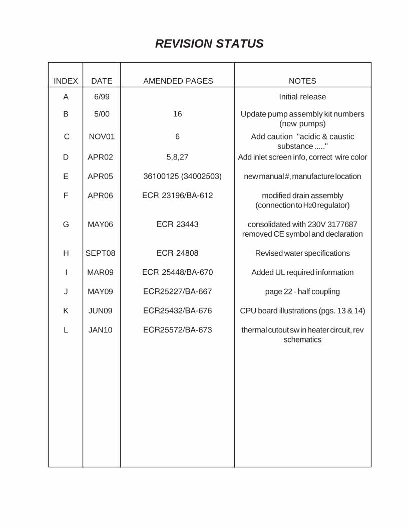
INDEX DATE NOTES
REVISION STATUS
Initial releaseA
AMENDED PAGES
6/99
Update pump assembly kit numbers(new pumps)
B 5/00 16
C NOV01 Add caution "acidic & causticsubstance ....."
6
D
E
F
G
H
I
J
K
L
APR02
APR05
APR06
MAY06
SEPT08
MAR09
MAY09
JUN09
JAN10
Add inlet screen info, correct wire color
new manual #, manufacture location
modified drain assembly(connection to H20 regulator)
consolidated with 230V 3177687removed CE symbol and declaration
Revised water specifications
Added UL required information
page 22 - half coupling
CPU board illustrations (pgs. 13 & 14)
thermal cutout sw in heater circuit, revschematics
5,8,27
36100125 (34002503)
ECR 23196/BA-612
ECR 23443
ECR 24808
ECR 25448/BA-670
ECR25227/BA-667
ECR25432/BA-676
ECR25572/BA-673
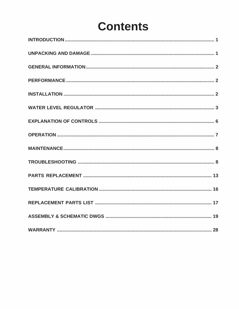
ContentsINTRODUCTION .................................................................................................................. 1
UNPACKING AND DAMAGE .............................................................................................. 1
GENERAL INFORMATION.................................................................................................. 2
PERFORMANCE ................................................................................................................. 2
INSTALLATION ................................................................................................................... 2
WATER LEVEL REGULATOR ........................................................................................... 3
EXPLANATION OF CONTROLS ........................................................................................ 6
OPERATION ........................................................................................................................ 7
MAINTENANCE................................................................................................................... 8
TROUBLESHOOTING ........................................................................................................ 8
PARTS REPLACEMENT .................................................................................................. 13
TEMPERATURE CALIBRATION ...................................................................................... 16
REPLACEMENT PARTS LIST ......................................................................................... 17
ASSEMBLY & SCHEMATIC DWGS ................................................................................. 19
WARRANTY ...................................................................................................................... 28

P/N: 3177890 1
UNPACKING AND DAMAGESave all packing material until unit is put intoservice. This merchandise was carefully packedand thoroughly inspected before leaving our factory.
Responsibility for safe delivery was assumed bythe carrier upon acceptance of the shipment;therefore, claims for loss or damage sustained intransit must be made upon the carrier by therecipient as follows:
1. Visible Loss or Damage: Note any externalevidence of loss or damage on the freight bill,or express receipt, and have it signed by thecarrier's agent. Failure to adequately describesuch external evidence of loss or damagemay result in the carrier's refusing to honoryour damage claim. The form required to filesuch claim will be supplied by the carrier.
2. Concealed Loss or Damage: Concealedloss or damage means loss or damage whichdoes not become apparent until themerchandise has been unpacked andinspected. Should either occur, make a writtenrequest for inspection by carrier's agent withinfifteen (15) days of the delivery date; then filea claim with the carrier since the damage isthe carrier's responsibility.
If you follow the above instructions carefully, wewill guarantee our full support of your claim to becompensated for loss or concealed damage.
DO NOT — FOR ANY REASON — RETURN THISUNIT WITHOUT FIRST OBTAININGAUTHORIZATION. In any correspondence toThermo, please supply the nameplate data,including catalog number and serial number.
INTRODUCTIONYour satisfaction and safety are important toThermo and a complete understanding of this unitis necessary to attain these objectives.
As the user of this apparatus, you have theresponsibility to understand the proper functionand operational characteristics of your bath. Thisinstruction manual should be thoroughly read andall operators given adequate training beforeattempting to place this unit in service. Awarenessof the stated cautions and warnings, andcompliance with recommended operatingparameters — together with maintenancerequirements — are important for safe andsatisfactory operation. The unit should be used forits intended application; alterations or modificationswill VOID THE WARRANTY.
WARNINGAS A ROUTINE LABORATORY PRECAUTION,ALWAYS WEAR SAFETY GLASSES WHENWORKING WITH THIS APPARATUS.
This product is not intended, nor can it be used, asa sterile or patient connected device. In addition,this apparatus is not designed for use in Class I, IIor III locations as defined by the National ElectricalCode.
CAUTIONWHEN UNPACKING THIS PRODUCT, TWOPERSONS ARE REQUIRED TO LIFT THEWATER BATH AND PLACE IT ON A BENCH.
THE BENCH TOP MUST BE RIGID ANDSTRONG ENOUGH TO COMFORTABLYSUPPORT THE WEIGHT OF THE UNITWHEN FILLED WITH WATER.

P/N: 3177890 2
PERFORMANCE DATA
The following table identifies the specifications forthe Circulating Baths.
INSTALLATION
WARNINGINSTALLATION SHOULD BE COMPLETED BYQUALIFIED PERSONNEL ONLY.
Location - The most uniform operating conditionswill be obtained by placing the bath on a levelsurface in an area remote from drafts, ventilatingoutlets, radiators, and other rapidly changingambient conditions.
Environmental Conditions-This instrument is designed to operate safelyunder the following conditions:
• Indoor Use Only• Temperature: 5° to 40° C• Maximum Relative Humidity: 80% to 31°C,
decreasing linearly to 50% at 40°C• Maximum Altitude 2000 meters• Mains supply voltage fluctuation ±10%, or
per project plan• Installation (Overvoltage) Category II1
• Pollution Degree 22
1 Installation category (overvoltage category) definesthe level of transient overvoltage which the instrumentis designed to withstand safely. It depends on thenature of the electricity supply and its overvoltageprotection means. For example, in CAT II which isthe category used for instruments in installationssupplied from a supply comparable to public mainssuch as hospital and research laboratories and mostindustrial laboratories, the expected transientovervoltage is 2500V for a 230V supply and 1500V fora 120V supply.2 Pollution Degree describes the amount ofconductive pollution present in the operatingenvironment. Pollution Degree 2 assumes thatnormally only non-conductive pollution such as dustoccurs with the exception of occasional conductivitycaused by condensation.
GENERAL INFORMATION
Precision Circulating Baths are widely used inresearch and quality control. Their superbtemperature uniformity and stability makes themespecially desirable for legal or reference tests.
The microprocessor control panel houses allfunctions necessary to operate the bath. The 5push-button switches and single digital displaywindow allow the operator to adjust bathtemperature and temperature calibration via a singleset of controls.
The proportional integral temperature controlcoupled with agitation supplied by a centrifugalpump located in the control housing allows precisetemperature control. Use of the gable cover providedis required to maintain optimal temperaturesensitivity.
A high limit thermostat is provided and can be setto prevent heater runaway in the event oftemperature control failure.
The interior of the bath is constructed of stainlesssteel and is designed for operation with distilledwater or water solutions, such as water /ethyleneglycol with corrosion inhabitants added. The bodyis made from galvanized steel and is painted foradded protection. A drain is located at the far lefthand end of the bath. A stainless steel gable coveris also provided with the bath.
The 240-volt units are identical in appearance tothe 115-volt units.
With Cover
Model2864/2865
Model2866/2867
Model2868/2869
Uniformity 37°C ±0.05 ±0.05°C ±0.05
Sensitivity 37°C ±0.05 ±0.05°C ±0.05
Listing of Models Included In This Manual
CategoryNumber Model Volts Hertz Watts Amps
31666802864/2865
120 50/60 1050 8.8
3166682 240 50/60 1050 4.4
31666842866/2867
120 50/60 1550 12.9
3166685 240 50/60 1550 6.5
31666812868/2869
120 50/60 1550 12.9
3166683 240 50/60 1550 6.5

P/N: 3177890 3
WATER LEVEL REGULATOR(OPTIONAL)
INSTALLATION INSTRUCTIONS - Use thefollowing steps along with Figure 1 and 2 shown onthe following page.
1. Turn off unit, disconnect power & drain waterfrom the bath.
2. Unscrew drain plug from side of bath body.
3. Replace with elbow connector and reducingbushing (shipped loose). Note the reducingbushing is used on units built after February2006.
NOTETO INSURE GOOD SEAL, WRAP THREADSWITH TEFLON TAPE OR EQUIVALENTSEALER.
4. Tighten elbow connector so open end (tubefitting) faces straight down.
5. Place Water Level Regulator BracketAssembly on the lip of the bath pan (drain sideof the bath towards the rear of the unit). Thesmall flange with gasketing near the top of thebracket should rest against the inside of thebath pan. The other 2 flanges with gasketingshould rest against the outside of the bathbody.
6. Insert the plastic tubing (coming from thebottom of the water level regulator) into theelbow connector (at the drain) & tighten theelbow connector fitting firmly to insure a goodseal.
7. Uncoil Tygon tubing & press onto 1/4" HoseBarb Fitting (located at the top of water levelregulator). Hose clamps are provided to ensurea good seal.
8. Hook-up other end of the tygon tubing to watersupply & turn on water. (Water pressure shouldfall within the following range: MIN is approx. 15PSI, MAX is approx 75 PSI)
Maximum performance is assured across thefollowing temperature range:
• 15ºC to 45ºC
Electrical Connections -
IMPORTANTFor personal safety, this apparatus mustbe properly grounded.1. The power cord provided on this unit is
equipped with a three-prong (grounding) plugwhich mates with standard three-pronggrounding wall receptacle to minimize thepossibility of electric shock hazard from thisapparatus. If in doubt, the user should havethe wall receptacle and circuit checked by aqualified electrician to make sure thereceptacle can provide adequate current andis properly grounded.
2. Where a standard two-prong wall receptacleis encountered, it is the personal responsibilityand obligation of the user to have it replacedwith a properly grounded three-prong wallreceptacle. Do not, under anycircumstances, cut or remove the third(ground) prong from the power cord. Do notuse a two-prong adapter plug.
Determine the total amount of current being usedby other apparatus connected to the circuit that willbe used for this apparatus. It is critical that theadded current demand (see nameplate) of thisand other equipment used on the same circuitdoes not exceed the rating of the fuse or circuitbreaker.
CAUTIONThe power supply must be the same voltage asspecified on the nameplate.
The power cord is the MAINS disconnect. Be surethat it is easily reached to disconnect the unit fromthe power source.
To avoid build-up of mineral deposits and preventcorrosion, use only distilled water in the bath.Using chlorinated tap water or additives that containchlorine will void the manufacturer’s warranty.Similarly, high purity (deionized) water that doesnot fall into the 50K to 1M ohm range and 7 to 9 pHrange will also void the warranty. Contact TechnicalServices with any questions.
Electrolysis can damage stainless steel. This canoccur if an object is allowed to rest directly on thesurface, trapping moisture that becomes oxygenstarved but is surrounded by water containingoxygen. The resulting electrolytic action will pit orerode the stainless steel.

P/N: 3177890 4
WATER LEVEL REGULATOR ASSEMBLY
FIGURE 1SIDE VIEW OF BATH
FIGURE 2CUTAWAY FRONT VIEW OF BATH
NOTEWATER LINE MARKINGON THE WATER LEVELREGULATOR IS ANINDICATOR OF THEAPPROXIMATE WATERLEVEL THAT WILL BEMAINTAINED IN BATH.THE ASSEMBLY HASBEEN SET TOMAINTAINAPPROXIMATE 1-3/4"OF WATER. TO RAISETHE SET WATERLEVEL, LOOSENTHUMBSCREW &RAISE WATER LEVELREGULATOR TODESIRED LEVEL(COINCIDE WITHWATER LINE MARK) &TIGHTENTHUMBSCREW TOHOLD WATER LEVELREGULATOR IN PLACE.
NOTE:
DO NOT OVER-TIGHTEN THUMBSCREW
P/N: 3177890 5
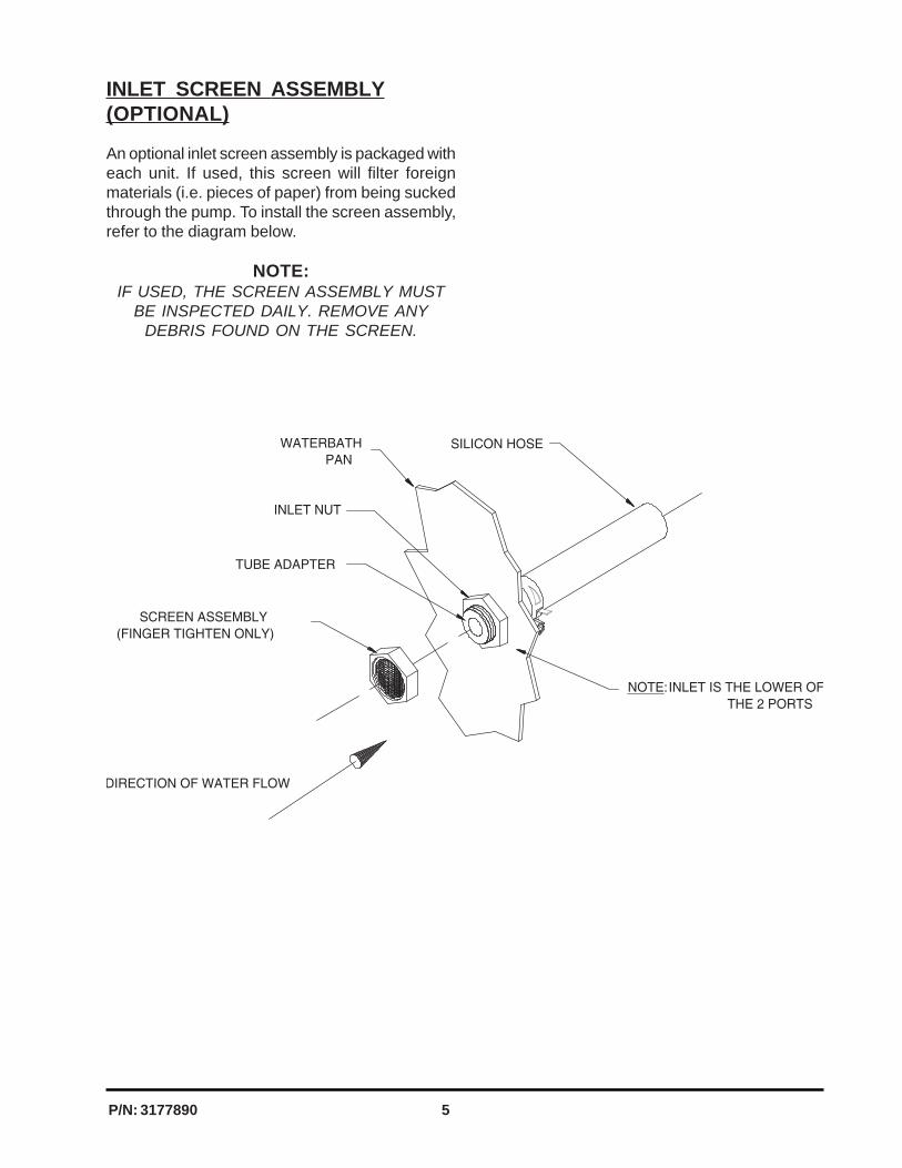
SILICON HOSEWATERBATH PAN
INLET NUT
TUBE ADAPTER
SCREEN ASSEMBLY(FINGER TIGHTEN ONLY)
DIRECTION OF WATER FLOW
NOTE: INLET IS THE LOWER OFTHE 2 PORTS
INLET SCREEN ASSEMBLY(OPTIONAL)
An optional inlet screen assembly is packaged witheach unit. If used, this screen will filter foreignmaterials (i.e. pieces of paper) from being suckedthrough the pump. To install the screen assembly,refer to the diagram below.
NOTE:IF USED, THE SCREEN ASSEMBLY MUST
BE INSPECTED DAILY. REMOVE ANYDEBRIS FOUND ON THE SCREEN.

P/N: 3177890 6
Pre ss ENTER to store the ne w value.
Pre ss Set Point.Pre ss or until value is d isp laye d .
To ad just te mpe rature :
ENTER
Set Point
Heate r On
Offse t
Bath Te mp ., °C
Se t Point
Actual
1
2
4
3
5
67
FIGURE A
EXPLANATION OF CONTROLS
Power Switch - The power switch is located onthe lower right hand side of the bath, it providespower for the entire unit.
Hi-Limit Thermostat - is located immediately tothe left of the power switch on the lower right handcorner of the bath. The high limit is an adjustablecontrol used to prevent thermal runaway in theevent that the primary control fails. After you havestabilized the bath temperature, use a standardscrewdriver to adjust the potentiometer. Whendelivered, the Hi-Limit is turned fully clockwise(highest setting). In this position the Hi-limit lightwill be OFF. Turn the potentiometer counter-clockwise until the Hi-Limit light is ON, andt h e n a d j u s tclockwise 1/8 ofa turn. Verify thatthe Hi-Limit lightis OFF. Now ifyour batht e m p e r a t u r erises above thedesired settingthe Hi-Limitprotection will beactivated.
Control PanelThe Controlpanel is locatedon top of the bathand provides pri-mary tempera-ture control. TheControl Panelcontains the fol-lowing features(See Figure A)
1. LED Display4-digit display used to show both actual and setpoint values for the temperature. Also showsconfiguration parameters when in configurationmode.
2. Heater on Lamp - the Heater on Lamp islighted when power is applied to the heatingelement.
3. Indicator Lamps - These lamps indicatewhich parameter (Actual Temp or Setpoint Temp)is displayed in LED window.
4. Set Point Key - The Set Point Key is used totoggle the display between actual bathtemperature and the setpoint value.
5. TemperatureSelection KeysThe TemperatureSelection Keysare used toselect the de-sired tempera-ture setpointvalue andare only activeafter theSet PointKey has beenpressed.
6. Enter Key -The Enter Keyis used to storea new set pointvalue.
7. Offset Key -The Offset Keyis used to adjustthe actualtemperaturevalue to matcha calibratedreferencethermometer.
P/N: 3177890 7
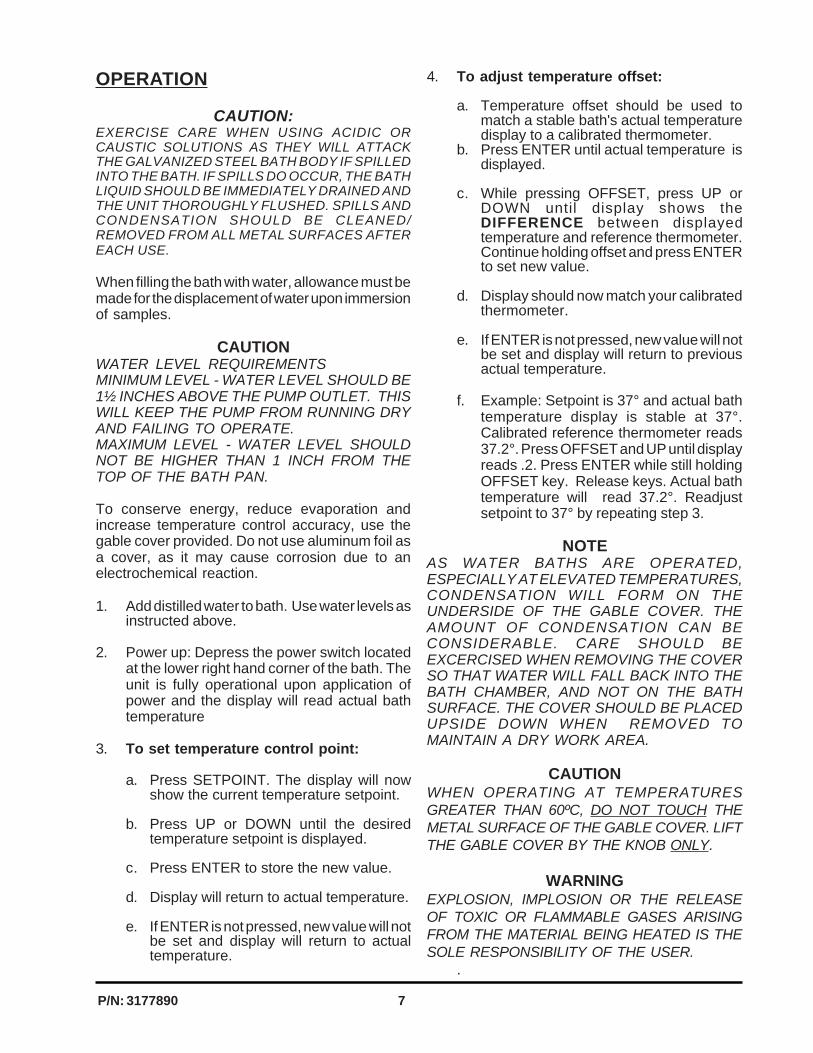
OPERATION
CAUTION:EXERCISE CARE WHEN USING ACIDIC ORCAUSTIC SOLUTIONS AS THEY WILL ATTACKTHE GALVANIZED STEEL BATH BODY IF SPILLEDINTO THE BATH. IF SPILLS DO OCCUR, THE BATHLIQUID SHOULD BE IMMEDIATELY DRAINED ANDTHE UNIT THOROUGHLY FLUSHED. SPILLS ANDCONDENSATION SHOULD BE CLEANED/REMOVED FROM ALL METAL SURFACES AFTEREACH USE.
When filling the bath with water, allowance must bemade for the displacement of water upon immersionof samples.
CAUTIONWATER LEVEL REQUIREMENTSMINIMUM LEVEL - WATER LEVEL SHOULD BE1½ INCHES ABOVE THE PUMP OUTLET. THISWILL KEEP THE PUMP FROM RUNNING DRYAND FAILING TO OPERATE.MAXIMUM LEVEL - WATER LEVEL SHOULDNOT BE HIGHER THAN 1 INCH FROM THETOP OF THE BATH PAN.
To conserve energy, reduce evaporation andincrease temperature control accuracy, use thegable cover provided. Do not use aluminum foil asa cover, as it may cause corrosion due to anelectrochemical reaction.
1. Add distilled water to bath. Use water levels asinstructed above.
2. Power up: Depress the power switch locatedat the lower right hand corner of the bath. Theunit is fully operational upon application ofpower and the display will read actual bathtemperature
3. To set temperature control point:
a. Press SETPOINT. The display will nowshow the current temperature setpoint.
b. Press UP or DOWN until the desiredtemperature setpoint is displayed.
c. Press ENTER to store the new value.
d. Display will return to actual temperature.
e. If ENTER is not pressed, new value will notbe set and display will return to actualtemperature.
4. To adjust temperature offset:
a. Temperature offset should be used tomatch a stable bath's actual temperaturedisplay to a calibrated thermometer.
b. Press ENTER until actual temperature isdisplayed.
c. While pressing OFFSET, press UP orDOWN until display shows theDIFFERENCE between displayedtemperature and reference thermometer.Continue holding offset and press ENTERto set new value.
d. Display should now match your calibratedthermometer.
e. If ENTER is not pressed, new value will notbe set and display will return to previousactual temperature.
f. Example: Setpoint is 37° and actual bathtemperature display is stable at 37°.Calibrated reference thermometer reads37.2°. Press OFFSET and UP until displayreads .2. Press ENTER while still holdingOFFSET key. Release keys. Actual bathtemperature will read 37.2°. Readjustsetpoint to 37° by repeating step 3.
NOTEAS WATER BATHS ARE OPERATED,ESPECIALLY AT ELEVATED TEMPERATURES,CONDENSATION WILL FORM ON THEUNDERSIDE OF THE GABLE COVER. THEAMOUNT OF CONDENSATION CAN BECONSIDERABLE. CARE SHOULD BEEXCERCISED WHEN REMOVING THE COVERSO THAT WATER WILL FALL BACK INTO THEBATH CHAMBER, AND NOT ON THE BATHSURFACE. THE COVER SHOULD BE PLACEDUPSIDE DOWN WHEN REMOVED TOMAINTAIN A DRY WORK AREA.
CAUTIONWHEN OPERATING AT TEMPERATURESGREATER THAN 60ºC, DO NOT TOUCH THEMETAL SURFACE OF THE GABLE COVER. LIFTTHE GABLE COVER BY THE KNOB ONLY.
WARNINGEXPLOSION, IMPLOSION OR THE RELEASEOF TOXIC OR FLAMMABLE GASES ARISINGFROM THE MATERIAL BEING HEATED IS THESOLE RESPONSIBILITY OF THE USER.
.

P/N: 3177890 8
MAINTENANCE
Cleaning: Stainless steel will resist corrosion;however, it is not impervious to it. Propermaintenance of the stainless steel bath chamberwill help ensure many years of service.
CAUTIONAVOID SPILLING HARSH CHEMICALS ONTOTHE BATH, AS CORROSION OF THESTAINLESS STEEL MAY RESULT.
IMPORTANTTHE USER HAS THE RESPONSIBILITYFOR PERFORMING APPROPRIATEDECONTAMINATION IF HAZARDOUSMATERIAL IS SPILT ON OR INSIDE THE BATH.
It should be cleaned regularly with mild soapywater and rinsed with distilled water. Should algaeor other undesirable microorganisms form on thetop of the bath media, add a little formaldehyde orquaternary ammonium germicide, available fromThermo (P/N 3166250).
CAUTIONDO NOT USE OTHER CLEANING ORDECONTAMINATION METHODS WITHOUTFIRST CONTACTING TECHNICAL SERVICESTO CHECK THAT THE PROPOSED METHODWILL NOT DAMAGE THE EQUIPMENT.
IMPORTANTIF IT IS NECESSARY TO USE THE FOLLOWINGCHEMICALS, LIMIT THE TIME TO A MAXIMUMOF FOUR HOURS. CLEAN SURFACESIMMEDIATELY AFTER USE.
-Aluminum Chloride -Barium Chloride-Bichloride of Mercury -Calcium Chloride-Carbolic Acid -Chlorinated Lime-Citric Acid (boiling) -Dakin's Solution-Ferrous Chloride -Mercury Salts-LysolMercuric Chloride -Phenol-Potassium Permanganate -Tartaric Acid-Potassium Thiocyanate -Stanous Chloride-Sodium Hypochlorite
CAUTIONNEVER USE THE FOLLOWING CHEMICALS:-Aqua Regia -Ferric Chloride-Iodine -Sodium Azide-Sulfuric Acid
Removing Discoloration: Should the stainlesssteel ever become discolored by iron rust, use thefollowing procedure to remove all traces of the rustand restore the stainless steel.
WARNINGOBSERVE THE FOLLOWING SAFETYPRECAUTIONS! USE HEAVY GLOVES OROTHER ADEQUATE HAND PROTECTION.WEAR GOGGLES OR OTHER ADEQUATEEYE PROTECTION. ONLY WORK IN AREASWITH ADEQUATE VENTILATION.
Prepare a solution of 20% nitric and 1.5%hydrochloric acid (if preferred, a 2% to 5% solutionof warm oxalic acid may be used). Swab solutionover surface, allowing it to remain until all rust isloosened. This will usually take 1 to 2 minutes.
As soon as rust is loosened, immediately flush withclean water until all acid is removed.
Screen assembly option: If this option is installed,inspect daily and remove any debris from thescreen.
Periodic Safety CheckTest the operation of the Hi-Limit thermostat, asdescribed on page 6, every three months.
TROUBLESHOOTING
WARNINGSERVICE SHOULD BE PERFORMED BY AQUALIFIED TECHNICIAN. BEFOREREPLACING ANY ELECTRICAL ORMECHANICAL COMPONENTS, UNPLUG THELINE CORD. IF ELECTRICAL POWER ISREQUIRED FOR SERVICE, USE EXTREMECARE.
Refer to Problems and Solutions for troubleshootinginformation on the baths. This guide provides thebasic information required to repair the bath.
P/N: 3177890 9
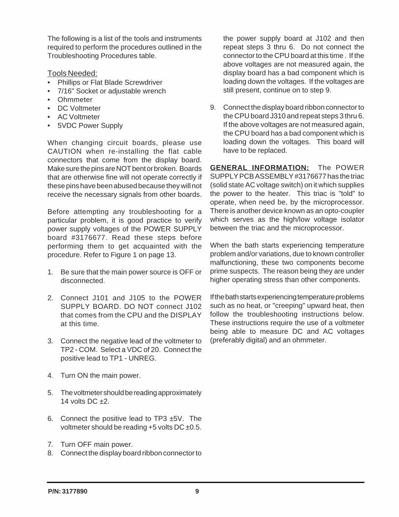
the power supply board at J102 and thenrepeat steps 3 thru 6. Do not connect theconnector to the CPU board at this time . If theabove voltages are not measured again, thedisplay board has a bad component which isloading down the voltages. If the voltages arestill present, continue on to step 9.
9. Connect the display board ribbon connector tothe CPU board J310 and repeat steps 3 thru 6.If the above voltages are not measured again,the CPU board has a bad component which isloading down the voltages. This board willhave to be replaced.
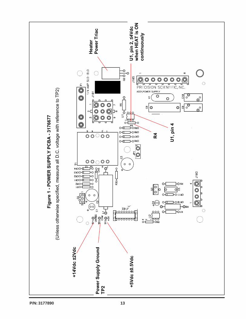
GENERAL INFORMATION: The POWERSUPPLY PCB ASSEMBLY #3176677 has the triac(solid state AC voltage switch) on it which suppliesthe power to the heater. This triac is "told" tooperate, when need be, by the microprocessor.There is another device known as an opto-couplerwhich serves as the high/low voltage isolatorbetween the triac and the microprocessor.
When the bath starts experiencing temperatureproblem and/or variations, due to known controllermalfunctioning, these two components becomeprime suspects. The reason being they are underhigher operating stress than other components.
If the bath starts experiencing temperature problemssuch as no heat, or "creeping" upward heat, thenfollow the troubleshooting instructions below.These instructions require the use of a voltmeterbeing able to measure DC and AC voltages(preferably digital) and an ohmmeter.
The following is a list of the tools and instrumentsrequired to perform the procedures outlined in theTroubleshooting Procedures table.
Tools Needed:• Phillips or Flat Blade Screwdriver• 7/16" Socket or adjustable wrench• Ohmmeter• DC Voltmeter• AC Voltmeter• 5VDC Power Supply
When changing circuit boards, please useCAUTION when re-installing the flat cableconnectors that come from the display board.Make sure the pins are NOT bent or broken. Boardsthat are otherwise fine will not operate correctly ifthese pins have been abused because they will notreceive the necessary signals from other boards.
Before attempting any troubleshooting for aparticular problem, it is good practice to verifypower supply voltages of the POWER SUPPLYboard #3176677. Read these steps beforeperforming them to get acquainted with theprocedure. Refer to Figure 1 on page 13.
1. Be sure that the main power source is OFF ordisconnected.
2. Connect J101 and J105 to the POWERSUPPLY BOARD. DO NOT connect J102that comes from the CPU and the DISPLAYat this time.
3. Connect the negative lead of the voltmeter toTP2 - COM. Select a VDC of 20. Connect thepositive lead to TP1 - UNREG.
4. Turn ON the main power.
5. The voltmeter should be reading approximately14 volts DC ±2.
6. Connect the positive lead to TP3 ±5V. Thevoltmeter should be reading +5 volts DC ±0.5.
7. Turn OFF main power.8. Connect the display board ribbon connector to

P/N: 3177890 10
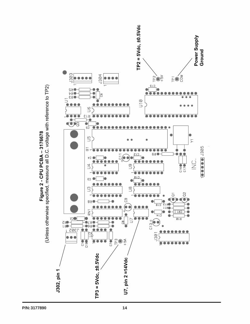
c. Measure the output of the temperaturesensor at J302 pins 2 & 3. Pin 3 being thereference or ground. The outputrelationship of voltage to °C is listed in thetable below. Compare the measuredvoltage to the temperatures listed todetermine if the probe is working.
5. The bath is not heating when it should berequesting heat. Voltage measurements aremade on the POWER SUPPLY BOARD#3176677. Refer to Figure 1 on page 13.
a. Select a setpoint temperature at least10°above what the actual temperature is.The bath should be requesting heat asindicated by the heater "ON" indicatorlamp on the front panel. It should be oncontinuously, not flashing.
b. Measure the voltage at U1-PIN 2 withrespect to TP2-COM. It should be nogreater than 4 VDC.
c. Measure the DC voltage across R4. Sincethe bath is requesting heat, there shouldbe current flowing through this resistormaking the voltage drop equal to 3VDC,±0.5.
d. If the last two steps are not as stated, thenmost likely the CPU board is bad and it willhave to be replaced.
e. Switch the voltmeter to an AC volts scalecapable of reading 120 volts.
f. Measure the voltage between U1-PIN 4and U1-PIN 6. It should be less than 1VAC.
g. If it is not, then most likely the opto-couplerU1 is bad and the POWER SUPPLY boardwill have to be replaced. If it is, continueon.
WARNINGTHE FOLLOWING TROUBLESHOOTINGINSTRUCTIONS REQUIRE THAT POWER BEON. ONLY QUALIFIED SERVICE PERSONNELSHOULD PERFORM THESE PROCEDURES.
Open the control cover and familiarize yourselfwith the POWER SUPPLY assembly #3176677.Locate the triac (Q2), the opto-isolater (U1), theresistor (R4), and the test point #2 (TP2-COM).The first measurements will be DC voltagemeasurements. A DC scale of at least 10 voltsshould be selected.
PROBLEMS & SOLUTIONS
*********** Problem A : No Heat *************
1. Verify that the setpoint temperature is greaterthan the actual water temperature.
2. Verify that the HIGH TEMP light is "OFF". If thelight is "ON", turn the HIGH LIMIT CONTROLfully clockwise.
3. Check temperature probe voltage reference.These measurements are on the CPU board#3176678. Refer to Figure 2 on page 14.
a. Place the negative lead of a DC voltmeteron TP1-COM test point. Measure thevoltage at U7-pin 2. It should beapproximately 14 volts DC. Now measurethe voltage at U7-Pin 6. It should beapproximately 5 volts DC. If the 14 volts ispresent but not the 5 volts, the CPU boardmust be replaced.
4. Check temperature probe.
a. Measure the bath water temperature andmake note of it. Make sure it will not changedrastically during this check.
b. With a DC voltmeter, measure the supplyof the temperature sensor at J302 pins 1 &3. It should be approximately 5 volts. If itis, then continue on to step C. If not, seeStep 3a.
Temp °C Volt Temp °C Volt
10 0.500V 60 1.400V
20 0.680V 70 1.580V
30 0.860V 80 1.760V
40 1.040V 90 1.940V
50 1.220V 99 2.218V

P/N: 3177890 11
c. Measure the DC voltage across R4. Thevoltage should be approximately zero volts.
d. If the last two steps are NOT as stated,then most likely the CPU board is bad andit will have to be replaced, otherwisecontinue on.
e. Switch the voltmeter to an AC volts scalecapable of reading 120 volts.
f. Measure the voltage between U1-PIN 4and U1-PIN 6. It should be line voltage 110VAC to 120 VAC.
g. If it is not, most likely the opto-coupler U1is bad and the POWER SUPPLY boardwill have to be replaced. If it is, continueon.
h. Measure the voltage directly across theheater. It should be approximately 0 VAC.
i. If it is not, then most likely the triac Q2 isbad,and the POWER SUPPLY board willhave to be replaced.
2. Check Temperature Probe. Problem A, Step 4.
h. Measure the voltage directly across theheater. It should be line voltage 110VAC to120 VAC.
i. If it is not, then most likely the triac Q2 isbad, and the POWER SUPPLY board willhave to be replaced.
6. Check heater.
a. Disconnect the bath from its electricalsupply.
b. Isolate the heater from any circuitry bydisconnecting one of the heater leads.
c. Using an ohmmeter, check the heaterresistance. Appropriate heater resistancevalues are listed below:If the resistance reads 0 or infinity, thenreplace the heater.
d. Check the resistance between the heaterleads and ground (green wire). If theresistance reads 0 ohms, replace theheater.
********* Problem B: Constant Heat *********
1. Bath is heating when it is not requesting heat.
a. Select a setpoint temperature at least 10°below the actual temperature. The bathshould not be requesting heat as indicatedby the HEATER ON indicator lamp on thefront panel. It should NOT be oncontinuously or even flashing.
b. Measure the voltage at U1-PIN 2 withrespect to TP2-COM. It should be no lessthan 4 VDC. Refer to Figure 1 on page 13.
*** Problem C: Unstable Temperature *** Control or Display
1. Use gable cover provided to improvetemperature control.
2. If control is stable but not at desiredtemperature, then check temperaturecalibration. Re-adjust if necessary.
3. Check Temperature Probe, Problem A, Step 4.
115 VOLT 230 VOLT
Model2864/2865 15 OHMS 60 OHMS
Model2866/2867 10 OHMS 40 OHMS
Model2868/2869 10 OHMS 40 OHMS

P/N: 3177890 12
** Problem D: Display Reads NNNN or UUUU **
The control boards have the ability to detect anOPEN or SHORTED temperature sensor. Thesetwo conditions are shown on the display as follows:
DISPLAY CONDITION
Before coming to the conclusion that the probe isbad when one of these displays appear, check theconnection of the probe to the circuit board forpolarity and alignment.
* Problem E: Display Reads all Eights (8888) *
1. The most common problem cause of thisproblem is the failure of the driver integratedcircuit on the DISPLAY/KEYBOARD board(#3176679). Replace it.
*** Problem F: Pump Does Not Circulate *** Water
1. Verify that the water level is above both thepump inlet and outlet.
2. If the pump is not running, verify that power isapplied to the bath. If power is present, checkwiring of pump to power switch. If wiring iscorrect, replace the pump.
3. If pump is running but water is not circulating,open the control panel and gently squeeze thelong piece of rubber tubing a few times to helpremove any air trapped within the pumpingsystem.
4. If water is still not circulating, check for foreignmatter in the pump inlet fitting.
SHORT CIRCUIT
OPEN CIRCUIT
P/N: 3177890 13
Fig
ure
1 -
PO
WE
R S
UP
PL
Y P
CB
A -
31
76
677
+1
4V
dc
±2
Vd
c
Po
we
r S
up
ply
Gro
un
d
TP
2 +5
Vd
c ±
0.5
Vd
c
U1
, p
in 2
, 4
Vd
c
wh
en
HE
AT
is
ON
co
nti
nu
ou
sly
R4
(Un
less o
therw
ise
sp
ecifie
d,
me
asu
re a
ll D
.C. vo
ltag
e w
ith
re
fere
nce
to
TP
2)
U1
, p
in 4
He
ate
r
Po
we
r T
ria
c
P/N: 3177890 14
U7
, p
in 2
1
4V
dc
TP
3 =
5V
dc
, ±0
.5V
dc
J3
02
, p
in 1
Po
we
r S
up
ply
Gro
un
d
TP
2 =
5V
dc
, ±0
.5V
dc
Fig
ure
2 -
CP
UP
CB
A –
31
76
67
8
(U
nle
ss o
therw
ise
sp
ecifie
d,
me
asu
re a
ll D
.C.
volta
ge
with
re
fere
nce
to T
P2
)
P/N: 3177890 15
PARTS REPLACEMENT
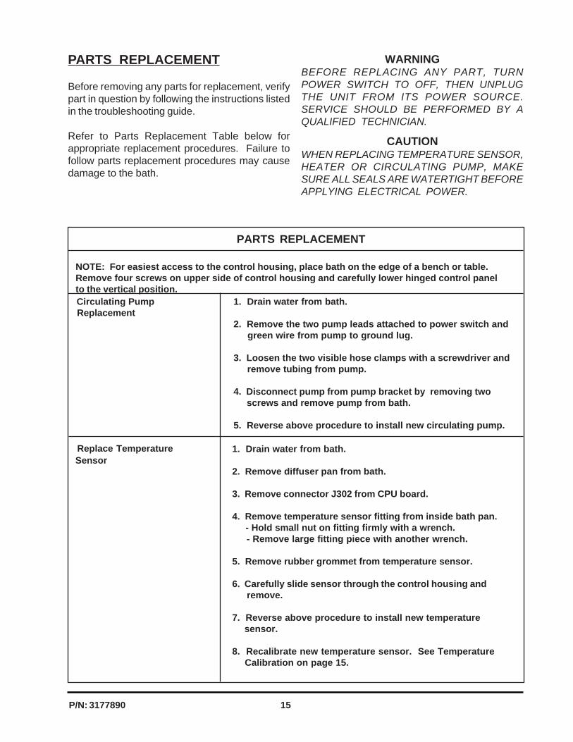
NOTE: For easiest access to the control housing, place bath on the edge of a bench or table.Remove four screws on upper side of control housing and carefully lower hinged control panelto the vertical position.
Circulating Pump Replacement
1. Drain water from bath.
2. Remove the two pump leads attached to power switch and green wire from pump to ground lug.
3. Loosen the two visible hose clamps with a screwdriver and remove tubing from pump.
4. Disconnect pump from pump bracket by removing two screws and remove pump from bath.
5. Reverse above procedure to install new circulating pump.
1. Drain water from bath.
2. Remove diffuser pan from bath.
3. Remove connector J302 from CPU board.
4. Remove temperature sensor fitting from inside bath pan. - Hold small nut on fitting firmly with a wrench. - Remove large fitting piece with another wrench.
5. Remove rubber grommet from temperature sensor.
6. Carefully slide sensor through the control housing and remove.
7. Reverse above procedure to install new temperature sensor.
8. Recalibrate new temperature sensor. See TemperatureCalibration on page 15.
Replace Temperature Sensor
PARTS REPLACEMENT
Before removing any parts for replacement, verifypart in question by following the instructions listedin the troubleshooting guide.
Refer to Parts Replacement Table below forappropriate replacement procedures. Failure tofollow parts replacement procedures may causedamage to the bath.
WARNINGBEFORE REPLACING ANY PART, TURNPOWER SWITCH TO OFF, THEN UNPLUGTHE UNIT FROM ITS POWER SOURCE.SERVICE SHOULD BE PERFORMED BY AQUALIFIED TECHNICIAN.
CAUTIONWHEN REPLACING TEMPERATURE SENSOR,HEATER OR CIRCULATING PUMP, MAKESURE ALL SEALS ARE WATERTIGHT BEFOREAPPLYING ELECTRICAL POWER.
P/N: 3177890 16
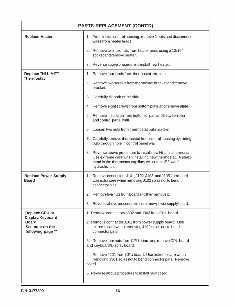
Replace Heater 1. From inside control housing, remove 2 nuts and disconnectwires from heater leads.
2. Remove two hex nuts from heater ends using a 13/16"socket and remove heater.
3. Reverse above procedure to install new heater.
Replace "HI LIMIT" 1. Remove four leads from thermostat terminals. Thermostat
2. Remove two screws from thermostat bracket and removebracket.
3. Carefully tilt bath on its side.
4. Remove eight screws from bottom plate and remove plate.
5. Remove insulation from bottom of pan and between panand control panel wall.
6. Loosen two nuts from thermostat bulb bracket.
7. Carefully remove thermostat from control housing by slidingbulb through hole in control panel wall.
8. Reverse above procedure to install new Hi Limit thermostat.Use extreme care when installing new thermostat. A sharpbend in the thermostat capillary will crimp off flow ofhydraulic fluid.
Replace Power Supply 1. Remove connectors J101, J102, J103, and J105 from board. Board Use extra care when removing J102 so as not to bend
connector pins.
2. Remove five nuts from board and then remove it.
3. Reverse above procedure to install new power supply board.
Replace CPU or 1. Remove connectors J302 and J303 from CPU board. Display/Keyboard Board 2. Remove connector J102 from power supply board. Use
extreme care when removing J102 so as not to bendconnector pins.
3. Remove four nuts from CPU board and remove CPU boardand Keyboard/Display board.
4. Remove J201 from CPU board. Use extreme care whenremoving J301 so as not to bend connector pins. Remove
board.
5. Reverse above procedure to install new board.
PARTS REPLACEMENT (CONT'D)
See note on thefollowing page **

P/N: 3177890 17
Replace CPU or Display/Keyboard Board See note below **
* Calibration of the low and high end of the sensor input is done at the factory. Field calibration of the sensormay be performed using the following technique: Enter the configuration routine and press the top left switchuntil a little "c" (Item H) is displayed. Add water that is around 10°C to the bath completely covering thesensor. Insert a calibrated thermometer. After the thermometer stabilizes, match the display setting to thethermometer reading by pressing the "UP" or "DOWN" push button switch. Press the top left switch. Thereadout will now display a big "C" (Item I). Remove water from the bath and add hot water of about 70 - 80°C.After the unit stabilizes, match readout display to temperature on thermometer and press the top left switch.Calibration is now complete.
**Note: When replacing CPU printed circuit board reprogramming may be necessary. Follow thoroughly instructions provided with the replacement circuit board.
PARTS REPLACEMENT (CONT'D)
6. The software must be configured to match the Bath model. To enter configuration mode, press the upper left pushbutton
switch while applying power. The upper left switch is labeled"Set Point." This switch is used to enter configurationcodes and steps through the different levels of configurations.
When a triangle is shown in the chart, the pushbutton is to bedepressed once for each symbol.
Immediately following power up with the switch depressed,the readout will display a 3-digit number. This is the softwarerevision. The readout will then begin to do a self-test ofdigits. Press the "Set Point" button once. The readout will display0000. Follow the listing below to complete theconfiguration.
A. Enter 37 using up/down arrows. Press "Set Point"
B. Enter 31 using up/down arrows. Press "Set Point"
C. Enter 2.0 using up/down arrows. Press "Set Point"
D. Enter 500 using up/down arrows. Press "Set Point"
E. Enter 1 using up/down arrows. Press "Set Point"
F. Display Not Used. Press "Set Point"
G. Display Not Used. Press "Set Point"
H. LOW TEMP CALIBRATION*LITTLE c. Factory Setting. Press "Set Point"
I. HI TEMP CALIBRATIONBIG C. Factory Setting. Press "Set Point"
Configuration is now complete

P/N: 3177890 18
TEMPERATURE CALIBRATION
The following instructions provide a step-by-stepprocedure for temperature calibration. Do notdeviate from the procedure or the calibration ofyour bath may be inaccurate.
CAUTIONTHIS PROCEDURE SHOULD ONLY BEPERFORMED AFTER INSTALLING A NEWTEMPERATURE PROBE INTO THE BATH.
1. Connect the temperature probe connector toJ302 on CPU board.
2. Turn Power switch to the OFF position.
3. Press and hold the SETPOINT key while turningPower ON.
4. The unit will now cycle through an LED displaytest. Press SETPOINT to end test.
5. The display will now read 0000. Press UP untildisplay reads 0012. Press SETPOINT.
NOTE:IF A VALUE OTHER THAN 0012 IS DISPLAYEDAND SETPOINT IS PRESSED, THE UNIT WILLRETURN TO NORMAL OPERATING MODE ANDDISPLAY WILL SHOW ACTUAL BATHTEMPERATURE.
6. The unit is now in Calibration mode. Rawcount value appears. Hit setpoint.
7. The display will now show cXX.X (XX.X is theactual bath temperature) - this is LowTemperature Calibration.
8. Place the temperature probe and a calibratedreference thermometer into an ice bath. PressUP or DOWN until the display value matchesthe reference thermometer. Press SETPOINTto store the new low temperature calibrationvalue.
9. The display will now show CXX.X - this is HighTemperature Calibration. (XX.X is the actualbath temperature).
10. Place the temperature probe and a calibratedreference thermometer into a steaming waterbath. Press UP or DOWN until the displayvalue matches the reference thermometer.Press SETPOINT to store the new hightemperature calibration value.
NOTEPRESSING OFFSET AT ANY TIME DURINGTHE CALIBRATION PROCESS WILL RETURNUNIT TO NORMAL OPERATION MODE ANDDISPLAY WILL SHOW ACTUAL BATHTEMPERATURE.

P/N: 3177890 19
REPLACEMENT PARTS LIST
ACCESSORY PARTS LIST
Model #2864/2865 Model #2866/2867 Model #2868/2869
3166680 3166682 3166684 3166685 3166681 3166683
120V 240V 120V 240V 120V 240V
Bath Pan Kit 3167140 3167141 3167142
Diffuser Pan Assy 3164495 3164479 3164500
PCB Kit, PowerSupply 3166924
PCB Assembly, CPU 3167119
PCB Assembly, Display 3176679
Heater Assembly Kit 3167138 3167139 3167136 3167137 3167136 3167137
Voltage Connector 3176698 3176699 3176698 3176699 3176698 3176699
Wire Harness 3176700
Temperature Probe Kit 3167144
'O' Ring Kit, Water Bath 3167129
Tubing Kit 3167145
"Hi-Limit" Thermostat Kit 3167143
ON/OFF Switch 3175318
Hi Limit Light, Amber 3177575 3173907 3177575 3173907 3177575 3173907
Line Cord 3178034 3179481 3178034 3179481 3178034 3179481
Power Cord Receptacle N/A 3179502 N/A 3179502 N/A 3179502
Mains Fuses (2 ea.) N/A 3172449 N/A 3175950 N/A 3175950
Power Supply Brd. Fuse N/A 3175930 N/A 3175930 N/A 3175930
Pump Assembly Kit 3167333 3167342 3167333 3167342 3167341 3167343
Drain Kit (includes Nut & O-Ring)
3166191
Model #2864/2865 Model #2866/2867 Model #2868/2869
3166680 3166682 3166684 3166685 3166681 3166683
Cover, Gable 3166565 3166208 3166230
Kit, Water Level Regulator 3166223
Sanitizer, Oakite 3166250
Diffuser Shelf, Raised 3165861

P/N: 3177890 20
ASSEMBLY AND SCHEMATIC DRAWINGS
FR
ON
T V
IEW

P/N: 3177890 21
115V
TO
P V
IEW
(WIT
H C
ON
TR
OL
CO
VE
R O
PE
N)

P/N: 3177890 22
230V
TO
P V
IEW
(WIT
H C
ON
TR
OL
CO
VE
R O
PE
N)
SC
RE
WL
OC
KW
AS
HE
RW
AS
HE
RP
UM
P
DIS
PL
AY
BO
AR
DN
UT
CP
U B
OA
RD
HE
AT
ER
PA
NS
CR
EW
TH
ER
MO
ME
TE
RH
OLD
ER
HE
AT
ER
BR
KT
.
PO
WE
R S
UP
PLY
BO
AR
D
SC
RE
WN
UT
PU
MP
BR
AC
KE
T
WA
SH
ER
LO
CK
WA
SH
ER
NU
TW
IRE
HA
RN
ES
S
VO
LT
AG
EC
ON
NE
CT
OR
MA
INS
FU
SE
S
PO
WE
R C
OR
D

P/N: 3177890 23
115V SIDE VIEW(WITH CONTROL COVER REMOVED AND WIRING EXCLUDED)
P/N: 3177890 24
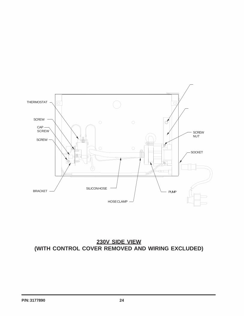
SCREWNUT
HOSE CLAMP
BRACKET
SCREW
CAPSCREW
SCREW
THERMOSTAT
230V SIDE VIEW(WITH CONTROL COVER REMOVED AND WIRING EXCLUDED)
PUMPSILICON HOSE
SOCKET

P/N: 3177890 25
O-RING SUPPLIEDWITH FITTING
NUT
FLEXFITTING
TEMPPROBE
ASSEMBLY
NUT
THERMOSTATCLIP
THERMOSTAT BULB(PART OF THERMOSTAT)
1/8” HALF COUPLING
PUMPOUTLET
SILICONEHOSE
HOSECLAMP
TO REMOVE TEMPERATURE PROBE:-HOLD NUT ON INSIDE OF PAN CLOSEST TO PAN WALL FIRMLY WITH WRENCH-REMOVE FLEX FITTING-SLIDE RUBBER GROMMET OVER END OF TEMPERATURE PROBE-SLIDE TEMPERATURE PROBE INTO CONTROL HOUSING
FRONT VIEW(CUTAWAY DETAIL OF TEMP PROBE & PUMP OUTLET)
TUBE ADAPTER

P/N: 3177890 26
FRONT VIEW(CUTAWAY DETAIL OF PUMP INLET & HEATER)
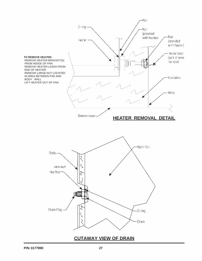
Nut
Bath Pan
Heater
Bath Body O-ring
Nut
(provided
with heater)
Heater Lead
(part of wire
harness)
Pump Inlet
Pump Inlet Fitting
High Temp
Cutout
P/N: 3177890 27
TO REMOVE HEATER:-REMOVE HEATER BRACKET(S) FROM INSIDE OF PAN-REMOVE HEATER LEADS FROM END OF HEATER-REMOVE LARGE NUT LOCATED IN AREA BETWEEN PAN AND BODY WALL-LIFT HEATER OUT OF PAN
HEATER REMOVAL DETAIL
CUTAWAY VIEW OF DRAIN
HEX NUT
P/N: 3177890 28
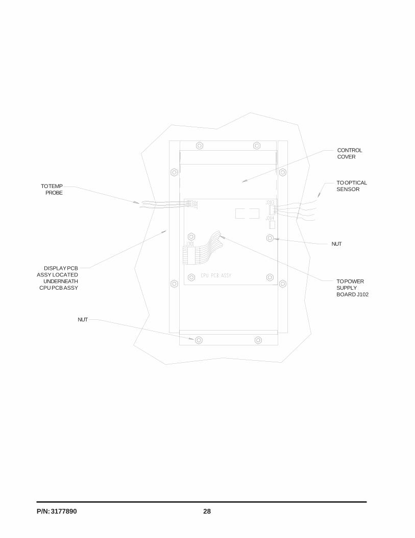
TO POWERSUPPLYBOARD J102
NUT
TO OPTICALSENSOR
CONTROLCOVER
NUT
TO TEMPPROBE
DISPLAY PCBASSY LOCATED
UNDERNEATHCPU PCB ASSY

P/N: 3177890 29
SC
HE
MA
TIC
DIA
GR
AM
120V
RE
DD
ISP
LAY
/ K
EY
BO
AR
D
AS
SE
MB
LY
TE
MP
ER
AT
UR
ES
EN
SO
R
GR
DV
ou
t
J303
+5V
J302
VO
LTA
GE
JU
MP
ER
P
CB
AS
SE
MB
LY
2
J201
1 43 5 6 16987 1110 12 13 14 15
CP
U P
CB
AS
SE
MB
LY
J3
01
BLA
CK
YE
LL
OW
1 2 3
1 21 21 2 333
51 2 3 4
21 43 5 6
51 2 3 4 76 98
16987
11
10
12
13
14
15
(1
20V
)
HIG
H T
EM
P L
IMIT
J101
RED
BL
AC
K
HR
1
DS
1B
LAC
K
L
AM
P
WH
ITE
PA
NE
LC
ON
TR
OL
GR
OU
ND
BLA
CK
(LI
NE
)
WH
ITE
(N
EU
TR
AL
)
H
IGH
TE
MP
LIM
ITS
WIT
CH
OP
EN
S O
N T
EM
P R
ISE
BLU
E
51 2 3 4 76 98
2
J102
1 43 5 6
22J1
05
11
43 5 6 7 8
43 5 6 7 8
J103
16987
11
10
12
13
14
15
1 2 3 4
PO
WE
R S
WIT
CH
S1
YE
LLO
W
BL
AC
K4 1
5 2
PU
MP
BLA
CK
BL
AC
K
E2
W1
S2 G
RE
EN CH
AS
SIS
GR
OU
ND
E1
HIG
HT
EM
PC
UT
OU
T

P/N: 3177890 30
SC
HE
MA
TIC
DIA
GR
AM
3437
6403
-230
VR
ED
DIS
PLA
Y /
KE
YB
OA
RD
3454
1709
AS
SE
MB
LY
TE
MP
ER
AT
UR
ES
EN
SO
R
GR
DV
out
J303
+5V
J302
VO
LTA
GE
JU
MP
ER
PC
B A
SS
EM
BLY
3437
3101
2
J201
1 43 5 6 16987 1110 12 13 14 15
CP
U P
CB
AS
SE
MB
LY
J301
BLA
CK
YE
LLO
W1 2 3
3437
3001
1 21 21 2 333
51 2 3 4
21 43 5 6
51 2 3 4 76 98
16987 1110 12 13 14 15
(230
V)
HIG
H T
EM
P L
IMIT
J101
RED
BLA
CK
HR
1
DS
1B
LAC
K
LAM
P
WH
ITE
PA
NE
LC
ON
TR
OL
GR
OU
ND
BR
OW
N(L
INE
)
BLU
E (
NE
UT
RA
L)
HIG
H T
EM
P L
IMIT
SW
ITC
H O
PE
NS
ON
TE
MP
RIS
E
BLU
E
3437
2501
51 2 3 4 76 98
2
J102
1 43 5 6
22J1
05
11
43 5 6 7 8
43 5 6 7 8
J103
16987 1110 12 13 14 151 2 3 4
PO
WE
R S
WIT
CH
S1
YE
LLO
W
BLA
CK
4 1
5 2
PU
MP
BLA
CK
BLA
CK
E2
W1
S2 YLW
/GR
N
CH
AS
SIS
GR
OU
ND
E1
FU
SE
S
HIG
HT
EM
PC
UT
OU
T

P/N: 3177890 31
Ther
mos
tat
Hig
h Li
mit
Ligh
tE2 (L
ocat
ed O
n
Con
trol
Pan
el)
Jum
per
Line
Cor
d
Pum
p
Hea
ter
Con
nect
or
To J
105
Pow
er
Sw
itch
Hig
h Te
mp
Cut
out
WIR
ING
CO
NN
ECTI
ON
DIA
GR
AM
(120
v)
P/N: 3177890 32
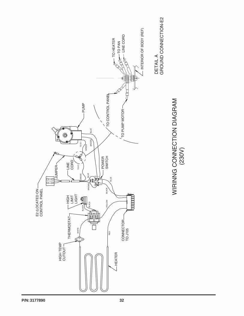
WIR
INN
G C
ON
NE
CT
ION
DIA
GR
AM
(230
V)
DE
TA
IL A
GR
OU
ND
CO
NN
EC
TIO
N-E
2
TO
HE
AT
ER
TO
PA
NLI
NE
CO
RD
INT
ER
IOR
OF
BO
DY
(R
EF
)
PU
MP
BLU
EB
RO
WN
GR
EE
N
TO
E1
TO
E1
PO
WE
RS
WIT
CH
LIN
EC
OR
D
E2
(LO
CA
TE
D O
NC
ON
TR
OL
PA
NE
L
GR
EE
N
BR
OW
NB
LUE
BLU
E
BLA
CK
YE
LLO
W
BLA
CK
BLA
CK
RE
DWH
ITE
JUM
PE
R
TH
ER
MO
ST
AT
HIG
HLI
MIT
LIG
HT
HE
AT
ER
CO
NN
EC
TO
RT
O J
105
TO
CO
NT
RO
L P
AN
EL
TO
PU
MP
MO
TO
R
HIG
H T
EM
PC
UT
OU
T

P/N: 3177890 33
TH
ER
MO
FIS
HE
R S
CIE
NT
IFIC
STA
ND
AR
D P
RO
DU
CT
WA
RR
AN
TY
The W
arr
anty
Period s
tart
s tw
o w
eeks fro
m the d
ate
your
equip
ment is
ship
ped fro
m o
ur
facili
ty. T
his
allo
ws for
ship
pin
g tim
e
so t
he w
arr
anty
will
go i
nto
effect
at
appro
xim
ate
ly t
he s
am
e t
ime y
our
equip
ment
is d
eliv
ere
d.
The w
arr
anty
pro
tection
exte
nds t
o a
ny s
ubsequent
ow
ner
during t
he f
irst
year
warr
anty
period.
Du
rin
g t
he
first
ye
ar,
co
mp
on
en
t pa
rts p
rove
n t
o b
e n
on
-co
nfo
rmin
g in
ma
teria
ls o
r w
ork
ma
nsh
ip w
ill b
e r
epa
ire
d o
r re
pla
ce
d
at
Therm
o's
expense,
labor
inclu
ded.
Insta
llation a
nd c
alib
ration a
re n
ot
covere
d b
y t
his
warr
anty
agre
em
ent. T
he T
echnic
al
Serv
ices D
epart
ment
must
be conta
cte
d fo
r w
arr
anty
dete
rmin
ation and direction prior
to perf
orm
ance of
any re
pairs.
Expendable
ite
ms,
gla
ss,
filters
and g
askets
are
exclu
ded f
rom
this
warr
anty
.
Repla
cem
ent
or
repair o
f com
ponents
part
s o
r equip
ment
under
this
warr
anty
shall
not
exte
nd t
he w
arr
anty
to e
ither
the
equip
ment or
to the c
om
ponent part
beyond the o
rigin
al w
arr
anty
period. T
he T
echnic
al S
erv
ices D
epart
ment m
ust giv
e p
rior
appro
val
for
retu
rn o
f any c
om
ponents
or
equip
ment. A
t T
herm
o's
option,
all
non-c
onfo
rmin
g p
art
s m
ust
be r
etu
rned t
o
Therm
o F
ish
er
Scie
ntific p
osta
ge p
aid
and r
epla
cem
ent
part
s a
re s
hip
ped F
OB
destination.
TH
IS W
AR
RA
NT
Y IS
E
XC
LU
SIV
E A
ND
IN
L
IEU
O
F A
LL
O
TH
ER
W
AR
RA
NT
IES
, W
HE
TH
ER
W
RIT
TE
N,
OR
AL
O
R
IMP
LIE
D.
NO
WA
RR
AN
TIE
S O
F M
ER
CH
AN
TA
BIL
ITY
OR
FIT
NE
SS
FO
R A
PA
RT
ICU
LA
R P
UR
PO
SE
SH
AL
L A
PP
LY.
Therm
o s
hall
not
be l
iable
for
any i
ndirect
or
consequential
dam
ages i
nclu
din
g,
without
limitation,
dam
ages r
ela
ting t
o l
ost
pro
fits
or
loss o
f p
rod
ucts
.
Your
local
Therm
o S
ale
s O
ffic
e i
s r
eady t
o h
elp
with c
om
pre
hensiv
e s
ite p
repara
tion i
nfo
rmation b
efo
re y
our
equip
ment
arr
ives.
Printe
d instr
uction m
anuals
care
fully
deta
il equip
ment
insta
llation,
opera
tion a
nd p
reventive m
ain
tenance.
If e
quip
ment
serv
ice
is r
equired,
ple
ase c
all
your
Technic
al S
erv
ices D
epart
ment
at
1-8
00-4
38-4
851 (
US
A a
nd C
anada)
or
1-7
40-3
73-4
763. W
e're r
eady to a
nsw
er
your
questions o
n e
quip
ment w
arr
anty
, opera
tion, m
ain
tenance, serv
ice a
nd s
pecia
l
applic
ation.
Outs
ide t
he U
SA
, conta
ct
your
local dis
trib
uto
r fo
r w
arr
anty
info
rmation.
Rev.
4
4/0
9
ISO
9001
REGI
STER
ED
P/N: 3177890 34
TH
ER
MO
FIS
HE
R S
CIE
NT
IFIC
IN
TE
RN
AT
ION
AL
DE
AL
ER
WA
RR
AN
TY
Th
e W
arr
an
ty P
erio
d s
tart
s t
wo
mo
nth
s f
rom
th
e d
ate
yo
ur
eq
uip
me
nt
is s
hip
pe
d f
rom
ou
r fa
cili
ty.
Th
is a
llow
s f
or
sh
ipp
ing
tim
e s
o t
he
wa
rra
nty
will
go
in
to e
ffe
ct
at
ap
pro
xim
ate
ly t
he
sa
me
tim
e y
ou
r e
qu
ipm
en
t is
de
live
red
. T
he
wa
rra
nty
pro
tec-
tio
n e
xte
nd
s t
o a
ny s
ub
se
qu
en
t o
wn
er
du
rin
g t
he
first
ye
ar
wa
rra
nty
pe
rio
d.
De
ale
rs w
ho
sto
ck o
ur
eq
uip
me
nt
are
allo
we
d
an
ad
ditio
na
l six
mo
nth
s fo
r d
eliv
ery
an
d in
sta
llatio
n, p
rovid
ed
th
e w
arr
an
ty c
ard
is c
om
ple
ted
an
d r
etu
rne
d to
th
e T
ech
nic
al
Se
rvic
es D
epa
rtm
en
t.
Du
rin
g th
e first ye
ar,
co
mp
on
en
t pa
rts p
rove
n to
be
no
n-c
on
form
ing
in m
ate
ria
ls o
r w
ork
ma
nsh
ip w
ill b
e r
epa
ire
d o
r re
pla
ce
d
at T
he
rmo
's e
xp
en
se
, la
bo
r e
xclu
de
d. In
sta
llatio
n a
nd
ca
libra
tio
n a
re n
ot co
ve
red
by th
is w
arr
an
ty a
gre
em
en
t. T
he
Te
ch
nic
al
Se
rvic
es D
epa
rtm
en
t m
ust
be
co
nta
cte
d f
or
wa
rra
nty
de
term
ina
tio
n a
nd
dire
ctio
n p
rio
r to
pe
rfo
rma
nce
of
an
y r
epa
irs.
Exp
en
da
ble
ite
ms,
gla
ss,
filte
rs,
rea
ge
nts
, tu
bin
g,
an
d g
aske
ts a
re e
xclu
de
d f
rom
th
is w
arr
an
ty.
Re
pla
ce
me
nt
or
repa
ir o
f co
mp
on
en
ts p
art
s o
r e
qu
ipm
en
t u
nd
er
this
wa
rra
nty
sh
all
no
t e
xte
nd
th
e w
arr
an
ty t
o e
ith
er
the
eq
uip
me
nt o
r to
th
e c
om
po
ne
nt pa
rt b
eyo
nd
th
e o
rig
ina
l wa
rra
nty
pe
rio
d. T
he
Te
ch
nic
al S
erv
ice
s D
epa
rtm
en
t m
ust g
ive
prio
r
ap
pro
va
l fo
r re
turn
of
an
y c
om
po
ne
nts
or
eq
uip
me
nt.
At
Th
erm
o's
op
tio
n,
all
no
n-c
on
form
ing
pa
rts m
ust
be
re
turn
ed
to
Th
erm
o p
osta
ge
pa
id a
nd
re
pla
ce
me
nt
pa
rts a
re s
hip
pe
d F
OB
de
stin
atio
n.
TH
IS W
AR
RA
NT
Y I
S E
XC
LU
SIV
E A
ND
IN
LIE
U O
F A
LL
OT
HE
R W
AR
RA
NT
IES
, W
HE
TH
ER
WR
ITT
EN
, O
RA
L O
R
IMP
LIE
D.
NO
WA
RR
AN
TIE
S O
F M
ER
CH
AN
TA
BIL
ITY
OR
FIT
NE
SS
FO
R A
PA
RT
ICU
LA
R P
UR
PO
SE
SH
AL
L A
PP
LY
.
Th
erm
o s
ha
ll n
ot
be
lia
ble
fo
r a
ny in
dire
ct
or
co
nse
qu
en
tia
l d
am
ag
es in
clu
din
g,
with
ou
t lim
ita
tio
n,
da
ma
ge
s r
ela
tin
g t
o lo
st
pro
fits
or
loss o
f p
rod
ucts
.
Yo
ur
loca
l T
he
rmo
Sa
les O
ffic
e i
s r
ea
dy t
o h
elp
with
co
mp
reh
en
siv
e s
ite
pre
pa
ratio
n i
nfo
rma
tio
n b
efo
re y
ou
r e
qu
ipm
en
t
arr
ive
s.
Prin
ted
in
str
uctio
n m
an
ua
ls c
are
fully
de
tail
eq
uip
me
nt
insta
llatio
n,
op
era
tio
n a
nd
pre
ve
ntive
ma
inte
na
nce
.
Co
nta
ct
yo
ur
loca
l d
istr
ibu
tor
for
wa
rra
nty
in
form
atio
n.
We
’re
re
ad
y t
o a
nsw
er
yo
ur
qu
estio
ns o
n e
qu
ipm
en
t w
arr
an
ty,
op
er-
atio
n,
ma
inte
na
nce
, se
rvic
e a
nd
sp
ecia
l a
pp
lica
tio
n.
Rev.
4
2/0
9
ISO
9001
REGI
STER
ED