Installation/Instruction Manual€¦ · · 2015-05-22Installation/Instruction Manual Be sure to...
12
1 Pressurized ventilators (for device cooling) Installation/Instruction Manual Be sure to read this manual before starting installation work to ensure correct and safe installation. Dealers and electrical contractors shall perform installation in accordance with the standards of each country. Ŷ7KLV IDQ LV D WKUHHSKDVH SURGXFW Check the type of power supply before performing the installation work. Ŷ7KLV IDQ LV IRU H[KDXVW XVH RQO\ Blades cannot be replaced and wire connections cannot be changed. Please read this manual carefully before use for proper and safe use. After reading, store the manual in a handy location for easy access. After you are finished with the installation work, be sure to give this manual to the customer. For customers For electrical contractors Model 200 V type 400 V type Blade diameter (cm) Indoor or outdoor 35 40 50 35 40 50 Indoor EF-35UDT-GL EF-40UET-GL EF-50UFT-GL EF-35UDT40A-GL EF-40UET40A-GL EF-50UFT40A-GL 1504876HA7801 Contents Explanation of installation work (For electrical contractors) 1. Safety Precautions ………………………………… 2 2. Usage and usage environment …………………… 3 3. Precautions before Installation …………………… 3 4. Outside Dimensions ………………………………… 4 5. Installation Procedure ……………………………… 5 6. Electrical Work ……………………………………… 6 7ULDO 2SHUDWLRQ ……………………………………… 6 Handling Explanation(For customers) 1. Safety Precautions ……………… 7 2. How to Use the Fan ……………… 8 3. Maintenance ……………………… 8 4. Maintenance and Inspection …… 9 5. Before Requesting Repair ……… 10 $IWHU6DOHV 6HUYLFH …………… 11 7. Specifications …………………… 11
-
Upload
trinhkhanh -
Category
Documents
-
view
215 -
download
2
Transcript of Installation/Instruction Manual€¦ · · 2015-05-22Installation/Instruction Manual Be sure to...
1
Pressurized ventilators (for device cooling)
Installation/Instruction Manual
Be sure to read this manual before starting installation work to ensure correct and safe installation. Dealers and electrical contractors shall perform installation in accordance with the standards of each country.
Check the type of power supply before performing the installation work.
Blades cannot be replaced and wire connections cannot be changed.
Please read this manual carefully before use for proper and safe use.After reading, store the manual in a handy location for easy access.
After you are finished with the installation work, be sure to give this manual to the customer.
For customers For electrical contractors
Model
200 V type
400 V type
Blade diameter (cm) Indoor or outdoor354050354050
Indoor
EF-35UDT-GLEF-40UET-GLEF-50UFT-GLEF-35UDT40A-GLEF-40UET40A-GLEF-50UFT40A-GL
1504876HA7801
ContentsExplanation of installation work (For electrical contractors)
1. Safety Precautions ………………………………… 22. Usage and usage environment …………………… 33. Precautions before Installation …………………… 34. Outside Dimensions ………………………………… 45. Installation Procedure ……………………………… 56. Electrical Work ……………………………………… 6
……………………………………… 6
Handling Explanation(For customers)1. Safety Precautions ……………… 72. How to Use the Fan………………83. Maintenance ……………………… 84. Maintenance and Inspection …… 95. Before Requesting Repair………10
…………… 117. Specifications …………………… 11

2
Explanation of installation work
Do not install the fan in a place where explosive dust or gas is generated or could be generated.- Failure to heed this warning may
result in explosion or fire.
Be sure to install the ground wire.- Device failure and electric leakage
may cause electric shock.
Do not use the fan for purposes other than ventilation and blowing air- Failure to heed this warning may
result in fire, electric shock or injury.
Do not use the fan at other than the rated voltage and frequency- Failure to heed this warning may
result in fire or electric shock.
Incorrect handling could result in death or serious injuryWARNING
Prohibited
Check grounding
When using the fan to exhaust air from a room where a combustion appliance for exhausting air through a chimney is installed, install an air supply opening large enough to prevent flowing of exhaust air back into the room.- Failure to heed this warning may
result in carbon monoxide poisoning.Install the fan in such a way that a wood structure covered with metal lath, wire lath, or metal sheeting and the metal body part do not directly contact each other.- It could cause fire when electrical
leakage occurs.Be sure to install the electric leakage breaker- Electric leakage may cause electric shock.
Because this product is designed to be installed at a higher location, install the product at least 2.3 m above the floor.- Failure to heed this warning may
result in injury.
Be sure to turn off the distribution panel circuit breaker before proceeding with maintenance and inspection.- Failure to heed this warning may
result in electric shock or injury.
Follow instructions
Follow instructions
Follow instructions
Follow instructions
1. Safety Precautions
Do not install the fan in a location with high humidity such as a bathroom (relative humidity 90% or higher).- Failure to heed this warning may
result in electric shock or fire.Securely install the fan on a solid, vibration-free location.- Injury may result if the fan should fall.
Incorrect handling could result in injury or property damage to buildings and machinery
Do not install the fan in a place where it could be exposed to flame directly.- Failure to heed this warning may
result in fire.
Securely install blades and parts.- Injury could result if parts fall.Electrical contractors shall perform electrical work and grounding work.- Electrical work by a person other than
a qualified electrician could result in electric shock or fire.
Do not install the fan in a place where there is a possibility of snow accumulation or avalanche. - Injury could result if parts are
damaged or fall.
Electrical work must be performed according to the standards of each country. Never perform connection by hand-twisting wires. Furthermore, power lines must be connected inside a box and box cover for rigid metal conduit. - Connection failure and faulty wiring work
could result in electric shock or fire.
Wear gloves before proceeding with unpacking, installation, maintenance/ inspection and cleaning. - Failure to heed this warning may
result in injury caused by, for example, the edge of the plate.
CAUTION
Prohibited
Cannot be installed in a bathroom
The type and degree of danger resulting from incorrect handling are denoted by the following symbols.
For electrical contractors

3
-
-
-
-
--
-
3. Precautions before Installation
2. Usage and usage environment Environment and restriction condition Protection Rating IPXXClass of protection Class ⅠOver voltage category Class ⅡPollution degree Class ⅡPermissible Temp. in use - 15°C to 50°C (The unit must not be frozen.)Permissible Humidity in use 90% at 20°CPermissible Altitude in use 1000m or less
Installation condition Indoor installation

4
4. Outside DimensionsEF-35UDT-GL, EF-35UDT40A-GL
EF-40UET-GL, EF-40UET40A-GLEF-50UFT-GL, EF-50UFT40A-GL
Unit (mm)
EF-40UET-GLEF-40UET40A-GLEF-50UFT-GLEF-50UFT40A-GL
A
520
620
B
460
560
Model C
490
605
D
405
510
E
400
500
F
131
131
G
222
258
H
80
95
J
196
232
Unit (mm)
Rotation
Rotation
470434
470
434
φ415φ350φ355
181
221
189
701010
Power cable effective length 1 mVinyl cab tire cable4-core AWG18
Power cable effective length 1 mVinyl cab tire cable4-core AWG18
Ground wire
Nameplate
4×φ12 mounting hole
Air flow
Air flow AB
AB
φC
φDφE φ
F
G H1010
Ground wire4×φ14 mounting hole
Nameplate
J

5
5. Installation Procedure
Wear gloves when unpacking or installing. - Failure to heed this warning may result in injury
caused by, for example, the edge of the plate.Securely install the fan on a solid, vibration-free place - Injury may result if the fan should fall.
CAUTIONBecause this fan is designed to be installed in a higher location, install the fan at least 2.3 m above the floor.- Failure to heed this warning may result in
injury.
WARNING
When unclean air is discharged, a place where fresh air enters is required.Install an air intake port, which has a size equivalent to or larger than the mounting frame of the fan, at the opposite side to the fan installed side of the room.
1. Provide an opening and mount the mounting bolts in the locations indicated on the figure on the left.
2. Mount the fan.Put the mounting bolts through the mounting holes and then use washers and nuts to secure them properly.
Note: Do not use the knock out holes for product mounting. (Product vibration, drop/deformation cause)
B
B
30
Mounting boltOpening
Type B Bolt diameter35cm40cm50cm
370410510
434460560
M8M12M12
Unit (mm)
Remove the drain cap (drain plug) ... If the fan is used in a location with high humidityIf the fan is used in a location with high humidity, install the fan in such a way that the drain cap (drain plug) provided on the motor and motor cover comes to the bottom. Remove the drain cap (drain plug) on the bottom.Note:
In dusty places, use the fan with the drain cap (drain plug) attached and open the drain from time to time.
(With the motor cover) (Without the motor cover)
When the fan is directly installed on a wall surface as exhaust heat
Drain cap
Drain cap Drain cap(Drain plug)
Drain cap(Drain plug)
Mounting boltFan
Mounting holeWasher(commercially available)
Nut(commercially available)

6
6. Electrical WorkElectrical work must be performed according to the standards of each country. Never perform connection by hand-twisting wires. Furthermore, power lines must be connected inside a box and box cover for rigid metal conduit - Connection failure and faulty wiring work could
result in electric shock or fire.
CAUTIONDo not use the fan at other than the rated voltage and frequency - Failure to heed this warning may result
in fire or electric shock.Be sure to install the ground wire - Device failure and electric leakage
may cause electric shock.
WARNING
Perform connection after checking that the power supply is correct. If the fan is operated with the wrong power supply, the motor could burn out.Be sure to install an electric leakage breaker. Always ground the grounding terminal.Circuit breakers conforming to EN60947-2 must be used. Circuit breakers of which contact gaps are 3 mm or more must be used. We recommended a Mitsubishi Electric non-fuse circuit breaker (Model: NF32-SVF [Rated current: 15 A, number of poles: 3]). Connect the TN system to a 3-phase, 3-wire power supply.The ground wire must always be connected. For wires that are to be connected to the power cord including the grounding wire, use electrical wire with a copper conductor size of 0.75 mm2 or above rated for a voltage of 300 V between conductor and ground and a voltage of 500 V, 7 A, or above between conductors.To connect to the power supply, install a metal electrical conduit box near the fan installation area (within 0.8 m in direct distance) and make connections inside the box. Install another separate metal box, and connect the circuit breaker and the electromagnetic switch together inside the box.
Metal electrical conduit boxWithin
0.8 m
FanMotor
PEL1L2L3
Connection Diagram The terminals are labeled on the end of the power cord as shown left. (Ground is marked with this symbol: ) The conductor wire gauge for the power cord is 18 AWG (Min 0.824 mm2).
Metal electrical conduit box (ventilator's power cord connection)Electromagnetic switch
Circuit breaker
To protect against overload on the motor, use overload protection equipment that employs a magnetic switch (magnetic contact + thermal relay). Overload protection equipment must be attached for every unit. A magnetic switch conforming to EN60947-4-1 must be used. We recommend a magnetic switch manufactured by Mitsubishi (model: MSO-N10 (The specification is described in Table 1)). The setting current value of the magnetic switch must be set per the information described in Table 2.
Table 2. Magnetic Switch Setting Current Value
Power Supply ModelMagnetic Switch Setting
Current Value (A)HeaterDesig.
(A)50Hz 60Hz
Three-phase50/60Hz200-220V
EF-35UDT-GL 1.3 1.4 1.3EF-40UET-GL 2.3 2.7 2.5EF-50UFT-GL 3.2 3.2 3.6
Three-phase50/50/50/60/60Hz380/400/415/400/440V
EF-35UDT40A-GL 0.7 0.65 0.7EF-40UET40A-GL 1.2 1.2 1.3EF-50UFT40A-GL 1.7 1.7 1.7
7. Trial OperationAfter installation work, check the following items.1. Is the fan installed correctly?2. Is not the power cord damaged?3. Has grounding work been performed correctly?4. Is the power supply voltage correct?
Turn ON the breaker to perform trial operation.5. Is not there abnormal vibration or noise?
(Where there is an abnormality, stop operation and check the electrical work.)
6. Is the rotation direction reversed?(If the rotation direction is reversed, switch two of the three power wires.)
Coil (kW) Auxiliary Contact Standard (spec.)220-220V 380-440V 500-550V
2.2 2.7 2.7 1a (1b)Combination with Thermal Relay
Model Heater Desig.(A)TH-N12
(KP)0.12, 0.17, 0.24, 0.35, 0.5, 0.7, 0.9, 1.3,
1.7, 2.1, 2.5, 3.6, 5, 6.6, 9

7
Do no use the fan in such a way that it is started and stopped more than 50 times a day- Injury could result if parts are damaged or fall.
When the blades are stained badly, make sure to clean them.- Injury could result if parts are damaged or
fall due to vibration.Be sure to wear gloves during cleaning, maintenance and inspection.- Failure to heed this warning may result in injury
caused by, for example, the edge of the plate.
This appliance is not intended for use by persons (including children) with reduced physical, sensory or mental capabilities, or lack of experience and knowledge, unless they have been given supervision or instruction concerning use of the appliance by a person responsible for their safety.
Children should be supervised to ensure that they do not play with the appliance. (IEC60335-2-80/IEC60335-1) If the supply cord is damaged, it must be replaced by the manufacturer, its service agent, or similar qualified persons in order to avoid a hazard.
This appliance can be used by children aged from 8 years and above and persons with reduced physical, sensory or mental capabilities or lack of experience and knowledge if they have been given supervision or instruction concerning use of the appliance in a safe way and understand the hazards involved. Children shall not play with the appliance. Cleaning and user maintenance shall not be made by children without supervision. (EN60335-2-80/EN60335-1)
Incorrect handling could result in death or serious injury
Incorrect handling could result in injury or property damage to buildings and machinery
Do not use the fan when it is subject to abnormal vibration.- Injury may result if the fan or parts should fall.
If the fan will not be operated for a long time, be sure to turn off the circuit breaker on the power distribution panel.- Failure to heed this warning may result in
electric shock due to deteriorated insulation or fire due to electric leakage.
Refrain from immersing in water or splashing the product with water.- Failure to heed this warning could
result in short circuit, electric shock or fire.
Never make modification under any circumstances.Only qualified personnel can perform disassembly and repair.- Failure to heed this warning may
result in fire, electric shock or injury.For repair, contact the dealer from whom you purchased the fan.
Do not insert fingers or objects into the fan during operation as doing so is dangerous- Failure to heed this warning may
result in injury.Never touch the fan when it is stopped with the power on, when there is an abnormality (for example, if you smell burning), or when there is a power outage.- It may start suddenly, resulting in
injury or electric shock.
Turn off the distribution board circuit breaker before proceeding with cleaning, maintenance, and inspection.- Failure to heed this warning may
result in electric shock or injury.
Do not operate with wet hands.- Failure to heed this warning may
result in electric shock or injury.
WARNING CAUTION
Prohibited
No disassembly
Follow instructions
Follow instructions
No wet hands
No water exposure
Handling Explanation1. Safety Precautions
Touching prohibited
The type and degree of danger resulting from incorrect handling are denoted by the following symbols.
For customers

8
3. Maintenance
Cleaning of blades, etc.
Overall cleaning
Cleaning should be performed about every three months.
Note:- Do not use the following solvents when performing maintenance:
Wear gloves during cleaning and maintenance.
CAUTIONBe sure to turn off the distribution panel circuit breaker before proceeding with cleaning and maintenance.
WARNING
To operate ...To stop ... Do not insert fingers or objects into the fan
during operation as doing so is dangerous
Do not operate with wet hands
WARNING2. How to Use the Fan
9
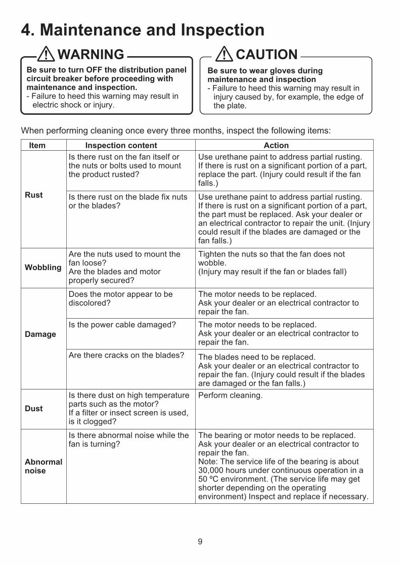
Be sure to wear gloves during maintenance and inspection- Failure to heed this warning may result in
injury caused by, for example, the edge of the plate.
CAUTIONBe sure to turn OFF the distribution panel circuit breaker before proceeding with maintenance and inspection.- Failure to heed this warning may result in
electric shock or injury.
WARNING
When performing cleaning once every three months, inspect the following items:
Is there rust on the fan itself or the nuts or bolts used to mount the product rusted?
Is there rust on the blade fix nuts or the blades?
Use urethane paint to address partial rusting.If there is rust on a significant portion of a part, replace the part. (Injury could result if the fan falls.)
Use urethane paint to address partial rusting. If there is rust on a significant portion of a part, the part must be replaced. Ask your dealer or an electrical contractor to repair the unit. (Injury could result if the blades are damaged or the fan falls.)
Tighten the nuts so that the fan does not wobble.(Injury may result if the fan or blades fall)
The motor needs to be replaced.Ask your dealer or an electrical contractor to repair the fan.The motor needs to be replaced.Ask your dealer or an electrical contractor to repair the fan.
The blades need to be replaced.Ask your dealer or an electrical contractor to repair the fan. (Injury could result if the blades are damaged or the fan falls.) Perform cleaning.
The bearing or motor needs to be replaced.Ask your dealer or an electrical contractor to repair the fan.Note: The service life of the bearing is about 30,000 hours under continuous operation in a 50 ºC environment. (The service life may get shorter depending on the operating environment) Inspect and replace if necessary.
Does the motor appear to be discolored?
Is the power cable damaged?
Are there cracks on the blades?
Is there dust on high temperature parts such as the motor? If a filter or insect screen is used, is it clogged?
Are the nuts used to mount the fan loose? Are the blades and motor properly secured?
Rust
Wobbling
Damage
Dust
Is there abnormal noise while the fan is turning?
Abnormal noise
Inspection content Item Action
4. Maintenance and Inspection

10
After the fan used for a long time for safety, it is recommended that the fan be checked even if the fan has no trouble.If the following phenomenon is found and cannot be corrected after inspection by the customer, turn off the breaker and ask your dealer or an electrical contractor to inspect and repair the fan. Please ask your dealer or an electrical contractor about the cost of repairs.
Note: The fan has a built-in auto-resetting thermal protector inside for protection against the damage by a fire. (200 V type) The above overload protection equipment will activate automatically to stop rotation in the case of locked operation, overloading, open-phase operation, application of incorrect voltage, or an ambient temperature in excess of the rated level. If this should occur, turn OFF the power and eliminate the cause of the problem. (Use of a filter or insect screen could cause clogging.) To restart operation, take the following action. <Action> Turn OFF the power, remove the cause and wait until the motor gets cool, then use the fan after confirming that the motor operates normally. If power is not switched OFF and continues to be supplied, the thermal protector will trip repeatedly, resulting in a contact failure or contact welding. If this should happen, the motor must be changed. Switch OFF the power and ask a qualified electrical contractor to change the motor.
Phenomenon Cause/ActionThe breaker is OFFThe fan does not
start even though the power is ON
Stop and operation are repeated (For 200 V type)
The overload protection equipment of the motor is running
The blades are looseThe main unit is looseThere are abnormal sounds from the bearing
Rust has occurred over a wide range
There is abnormal sound or vibration during operation
Something is caught on the bladesThe ambient temperature has exceeded 50 ºC
There is corrosion inside the motor
Turn ON the breaker
Turn OFF the power, remove the cause, wait until the motor gets cool and then turn ON the power (Note)
Tighten blade fix nutsTighten main unit fix nutsChange the bearing.Ask your dealer or an electrical contractor to repair the fan.Replace rusted parts.Ask your dealer or an electrical contractor to repair the fan.Remove the caught object
The fan cannot be used in a location where the ambient temperature exceeds 50 ºC. Lower the ambient temperature or use another model.Change the motor.Ask your dealer or an electrical contractor to repair the fan.
There is a burnt smell
5. Before Requesting Repair

11
ModelBlade
diameter (cm)
Voltage(V)
Frequency(Hz)
Air volume(m3/h)
Noise(dB)
Current (A)
Power Consumption
(W)
Maximum load
current(A)
Starting current
(A)Weight
(kg)
EF-35UDT-GL 35
Three-phase
200-220
503000 45-45.5 0.85-1.0 130-145 0.98-1.06 5.37-6.01 9.2
EF-40UET-GL 40 4800 52-52 1.45-1.67 245-273 1.90-1.95 15.0-16.0 13.2EF-50UFT-GL 50 7200 52-52 2.00-2.25 370-400 2.75-2.65 20.1-21.3 19.5EF-35UDT-GL 35
603600 49-49.5 0.8-0.85 180-185 1.15-1.14 4.96-5.28 9.2
EF-40UET-GL 40 5520 55-55.5 1.44-1.50 355-374 2.3-2.1 13.6-14.5 13.2EF-50UFT-GL 50 8400 56-56.5 2.1-2.1 530-560 2.75-2.7 18.4-19.3 19.5EF-35UDT40A-GL 35 Three-
phase380/400/415
503000 44.5/45/45 0.47/0.5/0.54 136/145/150 0.55/0.57/0.59 3.00/3.12/3.20 9.2
EF-40UET40A-GL 40 4800 51.5/52/52 0.76/0.78/0.86 265/275/285 1.0/1.02/1.04 7.00/7.35/7.50 13.2EF-50UFT40A-GL 50 7200 52/52/52 0.95/1.00/1.05 345/365/375 1.39/1.40/1.40 9.9/10.5/10.7 19.5EF-35UDT40A-GL 35 Three-
phase400/440
603600 49/49.5 0.44/0.47 185/195 0.54/0.56 2.89/3.05 9.2
EF-40UET40A-GL 40 5520 55/55.5 0.77/0.80 370/390 1.01/1.00 6.72/7.10 13.2EF-50UFT40A-GL 50 8400 56/56 1.03/1.05 540/545 1.46/1.28 9.56/10.3 19.5
For after-sales service, ask the sales agent from whom you purchased the product.To change the motor, contact your dealer and tell the fan model name to request repair.
6. After-Sales Service

12
EF-35UDT-GL EF-40UET-GL EF-50UFT-GL EF-35UDT40A-GL EF-40UET40A-GL EF-50UFT40A-GL1 28.5 30.5 31.8 28.7 30.6 31.82 Measurement Category A3 Static4 40 40 40 40 40 405 VSD N/A6 Year of Manufacture 2014 2014 2014 2014 2014 2014
7 Manufacturer Information
MITSUBISHI ELECTRIC CORPORATION Tokyo Bldg., 2-7-3, Marunouchi, Chiyoda-ku, Tokyo 100-8310, Japan
8 Model Number EF-35UDT-GL EF-40UET-GL EF-50UFT-GL EF-35UDT40A-GL EF-40UET40A-GL EF-50UFT40A-GL
9Motor Power Input (kW) 0.15 0.31 0.51 0.17 0.32 0.51Flow Rate (m3/s) 0.56 0.92 1.25 0.55 0.89 1.25Total Static Pressure (Pa) 80 99 145 83 106 148
10 Rotations per Minute 1436 1460 1445 1436 1458 144511 1
12
Information relevant for facilitating disassembly, recycling or disposal at end-of-life
This fan should be disposed of separately from household waste in line with local laws and regulations. When this fan reaches its end of life, dispose of it at your local waste collection point/recycling centre. The separate collection and recycling of this fan at the time of disposal will help conserve natural resources and ensure that it is recycled in a manner that protects human health and the environment. For more information please contact us at http://www.mitsubishielectric.co.jp/factory/sofuki/
13
Information relevant to minimise impact on the environment and ensure optimal life expectancy as regards installation, use and maintenance of the fan
<Cleaning of blades, etc.> Cleaning should be performed about every three months. <Overall cleaning>
once a year). - Do not use the following solvents when performing maintenance: Paint thinner, alcohol, benzene, gasoline, kerosene, spray solvents, alkaline detergents, chemicals from wipes, or detergents containing abrasives such as cleansers, or the like.
14
Description of additional items used when determining the fan energy
Model NameItem


![ReQ·131 v2 INSTRUCTION MANUAL - Lab:One RecordingsThe Copy To EQ [curve] button [F] will copy the current values on the active band over to the other memory slot in ReQ·131. Used](https://static.fdocuments.us/doc/165x107/5ffe3f8331b1ca3e4f405307/req131-v2-instruction-manual-labone-the-copy-to-eq-curve-button-f-will-copy.jpg)

