Installation, Start-Up and Service Instructions€¢ SMOKE DETECTOR/FIRE ALARM SHUTDOWN (FSD) •...
68
Manufacturer reserves the right to discontinue, or change at any time, specifications or designs without notice and without incurring obligations. Catalog No. 04-53500050-01 Printed in U.S.A. Form 50BV-4SI Pg 1 3-09 Replaces: 50BV-3SI Installation, Start-Up and Service Instructions CONTENTS Page SAFETY CONSIDERATIONS . . . . . . . . . . . . . . . . . . . . . . 2 GENERAL . . . . . . . . . . . . . . . . . . . . . . . . . . . . . . . . . . . . . . . . 2 MAJOR SYSTEM COMPONENTS . . . . . . . . . . . . . . . . . 3 Constant Volume (CV) Units . . . . . . . . . . . . . . . . . . . . . . 3 Variable Air Volume (VAV) Units . . . . . . . . . . . . . . . . . . 3 INSTALLATION . . . . . . . . . . . . . . . . . . . . . . . . . . . . . . . . 3-30 Step 1 — Complete Pre-Installation Checks . . . . . . 3 • EXAMINE THE UNIT • UNIT STORAGE • MODULAR UNITS Step 2 — Rig and Place Unit . . . . . . . . . . . . . . . . . . . . . 5 • REMOVE PACKAGING • UNIT LOCATION • UNIT PLACEMENT • ACOUSTICAL CONSIDERATIONS • ASSEMBLING MODULAR UNITS Step 3 — Install Ductwork . . . . . . . . . . . . . . . . . . . . . . . 20 • DUCT STATIC PRESSURE PROBE AND TUBING (VAV Only) • DUCT HIGH-STATIC (DHS) LIMIT SWITCH (VAV Only) Step 4 — Make Piping Connections . . . . . . . . . . . . . 21 • CONDENSER WATER PIPING (Water-Cooled Only) • EVAPORATOR CONDENSATE DRAIN • HOT WATER HEATING COIL (Optional) • WATER ECONOMIZER (Optional) • REMOTE REFRIGERANT PIPING (Remote Air-Cooled Only) Step 5 — Complete Electrical Connections. . . . . . 25 • POWER WIRING • CONTROL WIRING (CV Only) • REMOTE CONDENSER FAN CONTACTOR WIRING • CONTROL WIRING (VAV Only) • SUPPLY AIR TEMPERATURE SENSOR (SAT) • SMOKE DETECTOR/FIRE ALARM SHUTDOWN (FSD) • ALARM (ALARM) AND WARNING (WARN) OUTPUTS • REMOTE OCCUPANCY (ROCC) • RETURN AIR TEMPERATURE SENSOR (RAS) START-UP . . . . . . . . . . . . . . . . . . . . . . . . . . . . . . . . . . . . 30-48 General . . . . . . . . . . . . . . . . . . . . . . . . . . . . . . . . . . . . . . . . . 30 • CRANKCASE HEATERS • CONFIRM THE INPUT POWER PHASE SEQUENCE • INTERNAL WIRING • RETURN-AIR FILTERS • COMPRESSOR MOUNTING • REFRIGERANT SERVICE PORTS CV Unit Start-Up . . . . . . . . . . . . . . . . . . . . . . . . . . . . . . . . 31 • EVAPORATOR FAN • COOLING • HEATING (Heat Pump Units Only) Page VAV Unit Start-Up . . . . . . . . . . . . . . . . . . . . . . . . . . . . . . . 42 • PERFORM AUTOMATIC RUN TEST • CHECK VFD • POWER UP LID DISPLAY • LOG ON TO THE LID DISPLAY • CHANGE THE DEFAULT PASSWORD • SET THE CLOCK • CONFIGURE SCHEDULES • PROGRAM SET POINTS • CHECK SYSTEM PARAMETERS • DISPLAY ALARM HISTORY • CONFIGURE THE CUSTOM PROGRAMMING SELECTIONS • SET CONTROLLER ADDRESS • LOG OFF FROM THE CONTROLLER Sequence of Operation (CV Only) . . . . . . . . . . . . . . . 47 • WATER ECONOMIZER COOLING Sequence of Operation (VAV Only) . . . . . . . . . . . . . . 48 • SUPPLY FAN • COMPRESSOR COOLING • WATER ECONOMIZER COOLING • COOLING RESET Diagnostic Features (CV Only) . . . . . . . . . . . . . . . . . . 48 VAV Control and VFD Diagnostics . . . . . . . . . . . . . . . 48 SERVICE . . . . . . . . . . . . . . . . . . . . . . . . . . . . . . . . . . . . . . . . 49 Compressor Rotation . . . . . . . . . . . . . . . . . . . . . . . . . . . 49 Fan Motor Replacement . . . . . . . . . . . . . . . . . . . . . . . . . 49 MAINTENANCE . . . . . . . . . . . . . . . . . . . . . . . . . . . . . . 49-51 Cleaning Unit Exterior. . . . . . . . . . . . . . . . . . . . . . . . . . . 49 Coil Cleaning. . . . . . . . . . . . . . . . . . . . . . . . . . . . . . . . . . . . 49 Inspection. . . . . . . . . . . . . . . . . . . . . . . . . . . . . . . . . . . . . . . 49 Air Filters . . . . . . . . . . . . . . . . . . . . . . . . . . . . . . . . . . . . . . . 49 Condensate Drains. . . . . . . . . . . . . . . . . . . . . . . . . . . . . . 49 Water-Cooled Condensers . . . . . . . . . . . . . . . . . . . . . . 49 • GRAVITY FLOW METHOD • FORCED CIRCULATION METHOD Fan Motor Lubrication. . . . . . . . . . . . . . . . . . . . . . . . . . . 50 Fan Bearing Lubrication . . . . . . . . . . . . . . . . . . . . . . . . 50 Fan Sheaves . . . . . . . . . . . . . . . . . . . . . . . . . . . . . . . . . . . . 50 • ALIGNMENT Evaporator Fan Performance Adjustment . . . . . . . 51 • BELT TENSION ADJUSTMENT Charging the System . . . . . . . . . . . . . . . . . . . . . . . . . . . . 51 • REMOTE AIR-COOLED UNITS Compressor Oil . . . . . . . . . . . . . . . . . . . . . . . . . . . . . . . . . 51 TROUBLESHOOTING . . . . . . . . . . . . . . . . . . . . . . . . 51-65 Forcing and Clearing an Input or Output (VAV only) . . . . . . . . . . . . . . . . . . . . . . . . . . . . . . . . . . . . 54 START-UP CHECKLIST . . . . . . . . . . . . . . . . . . .CL-1, CL-2 OMNIZONE™ 50BV020-064 Water-Cooled and Remote Air-Cooled Indoor Self-Contained Systems and Water-Cooled Heat Pumps
Transcript of Installation, Start-Up and Service Instructions€¢ SMOKE DETECTOR/FIRE ALARM SHUTDOWN (FSD) •...
Manufacturer reserves the right to discontinue, or change at any time, specifications or designs without notice and without incurring obligations.Catalog No. 04-53500050-01 Printed in U.S.A. Form 50BV-4SI Pg 1 3-09 Replaces: 50BV-3SI
Installation, Start-Up and Service Instructions
CONTENTSPage
SAFETY CONSIDERATIONS . . . . . . . . . . . . . . . . . . . . . . 2 GENERAL . . . . . . . . . . . . . . . . . . . . . . . . . . . . . . . . . . . . . . . . 2MAJOR SYSTEM COMPONENTS . . . . . . . . . . . . . . . . . 3Constant Volume (CV) Units . . . . . . . . . . . . . . . . . . . . . . 3Variable Air Volume (VAV) Units . . . . . . . . . . . . . . . . . . 3INSTALLATION . . . . . . . . . . . . . . . . . . . . . . . . . . . . . . . . 3-30Step 1 — Complete Pre-Installation Checks . . . . . . 3• EXAMINE THE UNIT• UNIT STORAGE• MODULAR UNITSStep 2 — Rig and Place Unit . . . . . . . . . . . . . . . . . . . . . 5• REMOVE PACKAGING• UNIT LOCATION• UNIT PLACEMENT• ACOUSTICAL CONSIDERATIONS• ASSEMBLING MODULAR UNITSStep 3 — Install Ductwork . . . . . . . . . . . . . . . . . . . . . . . 20• DUCT STATIC PRESSURE PROBE AND TUBING
(VAV Only)• DUCT HIGH-STATIC (DHS) LIMIT SWITCH (VAV Only)Step 4 — Make Piping Connections . . . . . . . . . . . . . 21• CONDENSER WATER PIPING (Water-Cooled Only)• EVAPORATOR CONDENSATE DRAIN• HOT WATER HEATING COIL (Optional)• WATER ECONOMIZER (Optional)• REMOTE REFRIGERANT PIPING
(Remote Air-Cooled Only)Step 5 — Complete Electrical Connections. . . . . . 25• POWER WIRING• CONTROL WIRING (CV Only)• REMOTE CONDENSER FAN CONTACTOR WIRING• CONTROL WIRING (VAV Only)• SUPPLY AIR TEMPERATURE SENSOR (SAT)• SMOKE DETECTOR/FIRE ALARM SHUTDOWN (FSD)• ALARM (ALARM) AND WARNING (WARN) OUTPUTS• REMOTE OCCUPANCY (ROCC)• RETURN AIR TEMPERATURE SENSOR (RAS)START-UP . . . . . . . . . . . . . . . . . . . . . . . . . . . . . . . . . . . . 30-48General . . . . . . . . . . . . . . . . . . . . . . . . . . . . . . . . . . . . . . . . . 30• CRANKCASE HEATERS• CONFIRM THE INPUT POWER PHASE SEQUENCE• INTERNAL WIRING• RETURN-AIR FILTERS• COMPRESSOR MOUNTING• REFRIGERANT SERVICE PORTSCV Unit Start-Up . . . . . . . . . . . . . . . . . . . . . . . . . . . . . . . . 31• EVAPORATOR FAN• COOLING• HEATING (Heat Pump Units Only)
PageVAV Unit Start-Up . . . . . . . . . . . . . . . . . . . . . . . . . . . . . . . 42• PERFORM AUTOMATIC RUN TEST• CHECK VFD• POWER UP LID DISPLAY• LOG ON TO THE LID DISPLAY• CHANGE THE DEFAULT PASSWORD• SET THE CLOCK• CONFIGURE SCHEDULES• PROGRAM SET POINTS• CHECK SYSTEM PARAMETERS• DISPLAY ALARM HISTORY• CONFIGURE THE CUSTOM PROGRAMMING
SELECTIONS• SET CONTROLLER ADDRESS• LOG OFF FROM THE CONTROLLERSequence of Operation (CV Only) . . . . . . . . . . . . . . . 47• WATER ECONOMIZER COOLINGSequence of Operation (VAV Only) . . . . . . . . . . . . . . 48• SUPPLY FAN• COMPRESSOR COOLING• WATER ECONOMIZER COOLING• COOLING RESETDiagnostic Features (CV Only) . . . . . . . . . . . . . . . . . . 48VAV Control and VFD Diagnostics . . . . . . . . . . . . . . . 48SERVICE . . . . . . . . . . . . . . . . . . . . . . . . . . . . . . . . . . . . . . . . 49Compressor Rotation . . . . . . . . . . . . . . . . . . . . . . . . . . . 49Fan Motor Replacement . . . . . . . . . . . . . . . . . . . . . . . . . 49MAINTENANCE . . . . . . . . . . . . . . . . . . . . . . . . . . . . . . 49-51Cleaning Unit Exterior. . . . . . . . . . . . . . . . . . . . . . . . . . . 49Coil Cleaning. . . . . . . . . . . . . . . . . . . . . . . . . . . . . . . . . . . . 49Inspection. . . . . . . . . . . . . . . . . . . . . . . . . . . . . . . . . . . . . . . 49Air Filters . . . . . . . . . . . . . . . . . . . . . . . . . . . . . . . . . . . . . . . 49Condensate Drains. . . . . . . . . . . . . . . . . . . . . . . . . . . . . . 49Water-Cooled Condensers . . . . . . . . . . . . . . . . . . . . . . 49• GRAVITY FLOW METHOD• FORCED CIRCULATION METHODFan Motor Lubrication. . . . . . . . . . . . . . . . . . . . . . . . . . . 50Fan Bearing Lubrication . . . . . . . . . . . . . . . . . . . . . . . . 50Fan Sheaves . . . . . . . . . . . . . . . . . . . . . . . . . . . . . . . . . . . . 50• ALIGNMENTEvaporator Fan Performance Adjustment . . . . . . . 51• BELT TENSION ADJUSTMENTCharging the System . . . . . . . . . . . . . . . . . . . . . . . . . . . . 51• REMOTE AIR-COOLED UNITSCompressor Oil . . . . . . . . . . . . . . . . . . . . . . . . . . . . . . . . . 51TROUBLESHOOTING . . . . . . . . . . . . . . . . . . . . . . . . 51-65Forcing and Clearing an Input or Output
(VAV only) . . . . . . . . . . . . . . . . . . . . . . . . . . . . . . . . . . . . 54START-UP CHECKLIST . . . . . . . . . . . . . . . . . . .CL-1, CL-2
OMNIZONE™50BV020-064
Water-Cooled and Remote Air-CooledIndoor Self-Contained Systems and
Water-Cooled Heat Pumps

2
SAFETY CONSIDERATIONSInstalling, starting up, and servicing air-conditioning
components and equipment can be dangerous. Only trained,qualified installers and service mechanics should install, start-up, and service this equipment.
When working on the equipment, observe precautions inthe literature and on tags, stickers, and labels attached to theequipment. Follow all safety codes. Wear safety glasses andwork gloves.
GENERALOmnizone™ 50BV indoor packaged units are very flexible
for a variety of applications. These self-contained units areavailable as water-cooled or remote air-cooled air conditioningunits. The 50BV units are available with either constant vol-ume (CV) or variable air volume (VAV) controls. In addition,the 50BV unit is available as a water-cooled heat pump. Final-ly, Omnizone 50BV units are available in two cabinet styles.Nominal 18 through 30-ton units are constructed in a single-piece, unpainted galvanized cabinet. Nominal 30 through60-ton units are available as modular units, and can be takenapart for easier installation. Modular units are built using an un-painted, galvanized steel cabinet with steel framework, and canbe easily disassembled without breaking the refrigerant lines.See Table 1 for a model number reference by application.
Each unit contains multiple scroll compressors piped inseparate refrigerant circuits. Each water-cooled circuit includesa coaxial (tube-in-tube) condenser, TXV (thermostatic expan-sion valve), individual evaporator coils, and all interconnectingpiping. Water-cooled units are shipped fully charged withrefrigerant. Remote air-cooled units are shipped with a nitrogenholding charge.
Each unit is equipped with one or two forward-curved cen-trifugal blowers, to ensure quiet air delivery to the conditionedspace. Constant volume units operate at a single, adjustable fanspeed and provide zone temperature control using a standardcommercial thermostat. For VAV applications, the unit is sup-plied with a variable frequency drive(s) (VFD) that automati-cally adjusts blower speed to maintain a constant, adjustableduct static pressure. Compressors are automatically staged toprovide supply air temperature control (VAV applications) orzone temperature control using a two-stage commercial ther-mostat (CV applications).
The 50BV units have removable access panels for easyservicing. These panels allow access to controls, compressors,condensers, VFD(s) (if applicable), evaporator motors, blow-ers, belts, pulleys, and refrigeration components.
Table 1 — Model Number Reference By Application Type
LEGEND *All units are cooling only unless specified.
WARNING
Before performing service or maintenance operations onunit, turn off main power switch to unit and open all dis-connects. More than one disconnect switch may berequired to deenergize this equipment. Electric shock haz-ard can cause injury or death.
CAUTION
Use care in handling, rigging, and setting bulky equipment.
WARNING
DO NOT USE TORCH to remove any component. Systemcontains oil and refrigerant under pressure. To remove a component, wear protective gloves and gog-gles and proceed as follows:a. Shut off electrical power to unit.b. Recover refrigerant to relieve all pressure from sys-
tem using both high-pressure and low pressure ports.c. Traces of vapor should be displaced with nitrogen
and the work area should be well ventilated. Refrig-erant in contact with an open flame produces toxicgases.
d. Cut component connection tubing with tubing cutterand remove component from unit. Use a pan to catchany oil that may come out of the lines and as a gagefor how much oil to add to the system.
e. Carefully unsweat remaining tubing stubs when nec-essary. Oil can ignite when exposed to torch flame.
Failure to follow these procedures may result in personalinjury or death.
CAUTION
DO NOT re-use compressor oil or any oil that has beenexposed to the atmosphere. Dispose of oil per local codesand regulations. DO NOT leave refrigerant system open toair any longer than the actual time required to service theequipment. Seal circuits being serviced and charge withdry nitrogen to prevent oil contamination when timelyrepairs cannot be completed. Failure to follow these proce-dures may result in damage to equipment.
MODEL TYPE* AVAILABLE CAPACITY CONSTRUCTION CONTROLS50BVC Water-Cooled 18 to 30 nominal tons Single-piece CV50BVE Remote Air-Cooled 18 to 30 nominal tons Single-piece CV50BVQ Water-Cooled Heat Pump 18 to 30 nominal tons Single-piece CV50BVJ Water-Cooled 18 to 30 nominal tons Single-piece VAV50BVK Remote Air-Cooled 18 to 30 nominal tons Single-piece VAV50BVT Water-Cooled 30 to 60 nominal tons Modular CV50BVU Remote Air-Cooled 30 to 60 nominal tons Modular CV50BVV Water-Cooled Heat Pump 30 to 60 nominal tons Modular CV50BVW Water-Cooled 30 to 60 nominal tons Modular VAV50BVX Remote Air-Cooled 30 to 60 nominal tons Modular VAV
CV — Constant VolumeVAV — Variable Air Volume

3
MAJOR SYSTEM COMPONENTS
Constant Volume (CV) UnitsMAIN CONTROL BOARD (MCB) — The main controlboard for the 50BVC, E, Q, T, U, and V units provides bothcontrols and diagnostics including:• Condensate Overflow Protection prevents unit operation in
the event that the drain pan clogs (optional sensorsrequired).
• Random Start provides a programmable start with a rangeof 30 to 60 seconds.
• Anti-short Cycle Timer provides a 5-minute delay to pre-vent compressor short cycling.
• Low Pressure Bypass Timer bypasses the low-pressureswitch for 90 seconds to avoid nuisance trips during coldstart-up.
• High Pressure Switch Delay is a one-second delay that pre-vents nuisance trips at start-up.
• Brownout/Surge/Power Interruption Protection is a20-second moving scale that works in conjunction with therandom start timer to delay unit start when a nuisance lock-out would otherwise have occurred. This allows the waterpumps to restart and establish water flow.
• Alarm Output contacts provide remote fault indication.• Test/Service Pin is a jumper that reduces all time delay
settings to 6 seconds during troubleshooting or operationverification.
• Reset occurs after a 5-minute delay when a fault conditionoccurs. When the timer expires, the unit will restart. If thesame condition occurs a second time, the unit will be lockedout.
• Lockout Reset requires that the unit power be cycled at theunit controller via either the thermostat or unit disconnect.
NOTE: The refrigerant circuits on dual compressor modelsare completely independent. If either stage has a fault condi-tion the remaining stage will continue to operate withoutinterruption. A freeze (optional sensor required) or condensateoverflow lockout will shut down both refrigerant circuits. • LEDs are provided for diagnostic purposes.
Variable Air Volume (VAV) Units — The 50BVJ, K,W, and X units come equipped with a Carrier 6400 ComfortController and a VFD. Refer to the 50BV,XJ Controls, Opera-tion and Troubleshooting manual for details.NOTE: The VAV units utilize face split coils and should notbe operated below 50% of nominal airflow to prevent coilfreezing.
INSTALLATIONOmnizone™ 50BV units are intended for indoor installa-
tion only. Determine building alterations required to run piping,wiring, and ductwork. Read all installation instructions beforeinstalling the unit.
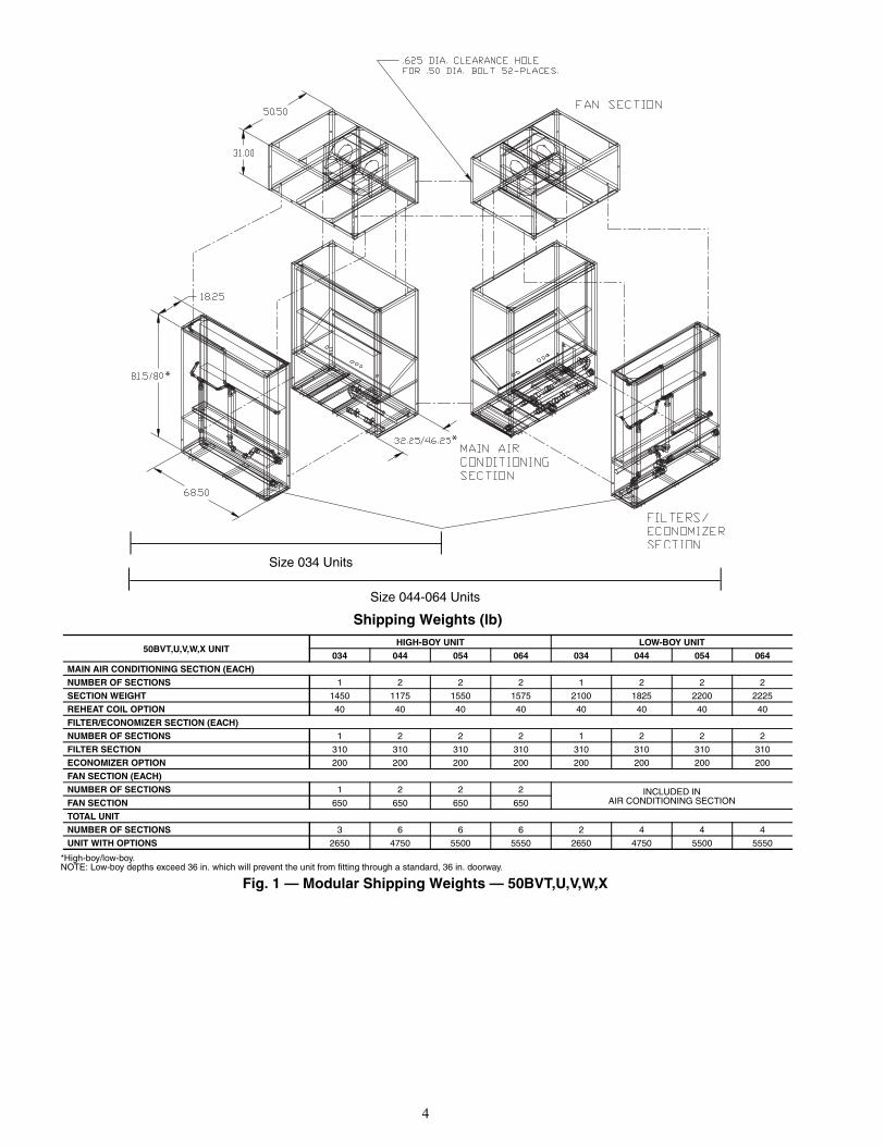
Step 1 — Complete Pre-Installation ChecksEXAMINE THE UNIT — Examine the unit for shippingdamage. File a claim with the transit company if damage isfound. Check the shipment for completeness. Verify that thenameplate electrical requirements match the available powersupply.UNIT STORAGE — The 50BV units are designed and pack-aged for indoor storage and use only. If the equipment is notneeded for immediate installation upon its arrival at the job site,it should be left in its shipping carton and stored in a clean, dryarea. Units must only be stored or moved in the normal uprightposition, as indicated by the “UP” arrows on each carton, at alltimes. DO NOT STACK UNITS.MODULAR UNITS — The 50BVT,U,V,W,X units are shippedin multiple sections for easy movement and installation. Theseparate modules (high-boy units only) will pass through a stan-dard 36-in. steel-framed door or service elevator. Circuit integri-ty is maintained because none of the refrigerant piping requiresdisconnection. Water piping connections are made with the useof heavy-duty bronze-bodied unions so no field welding or braz-ing is required. See Fig. 1 for unit weight and dimensions.NOTE: High-boy units ship as two pieces (air conditioning/filter section and blower section) and can be dissassembledinto 6 pieces. Low-boy units ship complete and will not fitthrough a 36 in. door. The low-boy unit’s filter section is inte-gral to unit and cannot be disassembled.
4
*
*
a50-8235
Shipping Weights (lb)
*High-boy/low-boy.NOTE: Low-boy depths exceed 36 in. which will prevent the unit from fitting through a standard, 36 in. doorway.
50BVT,U,V,W,X UNITHIGH-BOY UNIT LOW-BOY UNIT
034 044 054 064 034 044 054 064MAIN AIR CONDITIONING SECTION (EACH)NUMBER OF SECTIONS 1 2 2 2 1 2 2 2
SECTION WEIGHT 1450 1175 1550 1575 2100 1825 2200 2225
REHEAT COIL OPTION 40 40 40 40 40 40 40 40
FILTER/ECONOMIZER SECTION (EACH)NUMBER OF SECTIONS 1 2 2 2 1 2 2 2
FILTER SECTION 310 310 310 310 310 310 310 310
ECONOMIZER OPTION 200 200 200 200 200 200 200 200
FAN SECTION (EACH)NUMBER OF SECTIONS 1 2 2 2 INCLUDED IN
AIR CONDITIONING SECTIONFAN SECTION 650 650 650 650
TOTAL UNITNUMBER OF SECTIONS 3 6 6 6 2 4 4 4
UNIT WITH OPTIONS 2650 4750 5500 5550 2650 4750 5500 5550
Size 034 Units
Size 044-064 Units
Fig. 1 — Modular Shipping Weights — 50BVT,U,V,W,X

5
Step 2 — Rig and Place Unit — Use proper liftingand handling practices to avoid damage to the unit. Movemodular units with a fork truck using the baserails provided, oruse spreader bars and lifting straps as shown in Fig. 2.
For single piece units, use spreader bars and rigging straps iflifting with a crane to avoid damage to the unit. Otherwise,move with a fork truck using the shipping pallet.
Refer to Fig. 1 and 3-14 for unit dimensions.Refer to Tables 2A and 2B for physical data.
REMOVE PACKAGING — Remove all protective plastic,remove and discard unit top cover protector, filter cover,controller display protector, and water piping connectionpackaging.UNIT LOCATION — Locate the unit in an indoor areathat allows easy removal of the filters, access panels, andaccessories. Make certain enough space is available for servicepersonnel to perform maintenance or repairs. Provide sufficientroom to make all water, duct, and electrical connections. If theunit is located in a small mechanical equipment room, makesure adequate space is available for air to return freely to theunit. These units are not approved for outdoor installations andmust be installed inside the structure. Do not locate in areasthat are subject to freezing.UNIT PLACEMENT — Ensure that the floor is structurallystrong enough to support the weight of the equipment withminimum deflection. A good, level floor is required for properunit operation and to ensure proper fit-up and alignment of allbolt together and union coupled modules on modular units.ACOUSTICAL CONSIDERATIONS — Proper acousticalconsiderations are a critical part of every system’s design andoperation. Each system design and installation should bereviewed for its own unique requirements. For job specificrequirements, contact an acoustical consultant for guidance andrecommendations.
In general, to reduce noise, consider the following:• Locate mechanical room and ducts away from noise
sensitive locations. Whenever possible, work with thearchitect to locate the equipment rooms around theperimeters of restrooms, hallways, fire escapes, stairwells, etc., to reduce noise transmission. This allows not
only for isolation from radiated sound but also enablesthe contractor to route duct systems around sensitivelocations.
• Construct the equipment room of concrete block or use adouble offset stud wall with interwoven insulation. Sealall penetrations.
• Design the system for low total static pressure.• Use suitable vibration isolation pads or isolation springs
according to the design engineer's specifications.• A flexible canvas duct connector is recommended on
both the supply and return air sides of units to beconnected to system ductwork.
• Use a minimum of 15 ft of return ductwork between thelast air terminal or diffuser and the unit.
• Insulate supply and return ducts with 2-in., 3-lb densityinsulation.
• Round duct is recommended. If rectangular ductwork isused, keep aspect ratios as small as possible (i.e., as closeto square as possible).
• Avoid any direct line of sight from return air grillesinto the unit's return. If return air is to be ducted to anequipment room, an elbow should be installed within theequipment room.
• Running a return air drop to near the floor of the roomwill aid in sound attenuation.
• Do not exceed the recommended supply duct velocity of2,000 fpm.
• Do not exceed the recommended return duct velocity of1,000 fpm.
• Use turning vanes on 90-degree elbows.• Place isolation springs under each corner and under each
compressor if utilized.ASSEMBLING MODULAR UNITS — 50BVT,U,V,W,X30 to 60 ton units ship in pieces. Reassemble the unit. Use theloose hardware provided in the main air-conditioning sectionand the instructions below.
1. The filter/economizer section ships bolted to the main air-conditioning section and can be removed in the field(high-boy unit only). When reattaching the filter/econo-mizer section to the main air-conditioning section, placethe filter side of the filter/economizer section facing outand away from the main air conditioning section.
2. If the unit has 2 filter/economizer and 2 main air-conditioning sections (40 through 60 ton units), bolt theremaining filter/economizer section and main air-conditioning section together, as in Step 1 (high-boy unitonly).
3. For units with 2 filter/economizer and 2 main air-conditioning sections, use the provided unions to assem-ble the water connections between the 2 additionalsections joined in Step 2.
4. For units with multiple air conditioning sections, connectthe condensate drain hoses from the “B” side of the unitto the drain manifold on the “A” side of the unit.
5. For unit sizes 044-064, connect power wiring from themain terminal block in the “A” side of the unit to thepower terminal block in the “B” side of the unit.
6. For VAV units only, connect the plenum tubing, coiledbehind the VAV control panel, to the bulkhead fittingslocated in the discharge of the supply fan. This connectsthe high pressure supply to the high side of the duct highstatic pressure switch.
USESPREADERBAR TOPREVENTDAMAGETO UNIT
4 X 4 ABOVEAND BELOWRETURN DUCTCONNECTIONS
Fig. 2 — Modular Unit Rigging
a50-7257ef
CAUTION
Remove all shipping blocks, if any, under blower housingor damage to the fan may occur.
6
STANDARDBLOWERORIENTATION
OPTIONALBLOWERORIENTATION
STANDARDBLOWERORIENTATION
OPTIONALBLOWERORIENTATION
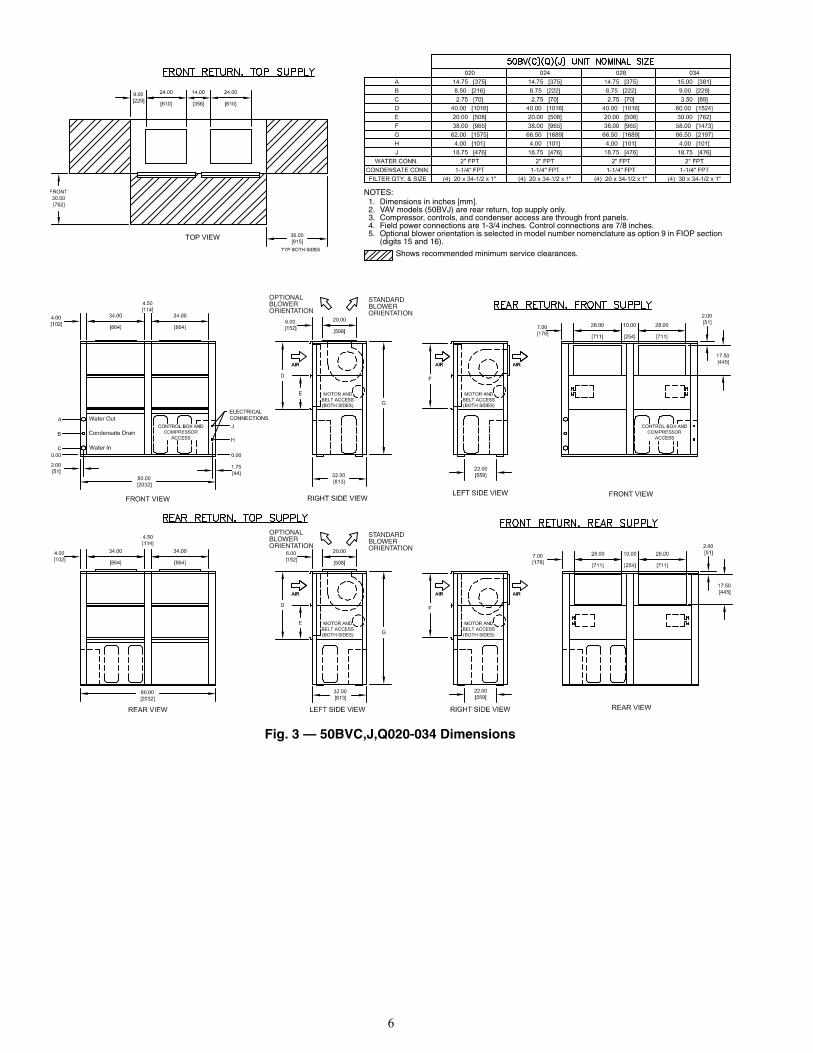
Fig. 3 — 50BVC,J,Q020-034 Dimensions
NOTES:1. Dimensions in inches [mm].2. VAV models (50BVJ) are rear return, top supply only.3. Compressor, controls, and condenser access are through front panels.4. Field power connections are 1-3/4inches. Control connections are 7/8inches.5. Optional blower orientation is selected in model number nomenclature as option 9 in FIOP section
(digits 15 and 16).
Shows recommended minimum service clearances.
a50-8199
7
STANDARDBLOWERORIENTATION
OPTIONALBLOWERORIENTATION
STANDARDBLOWERORIENTATION
OPTIONALBLOWERORIENTATION
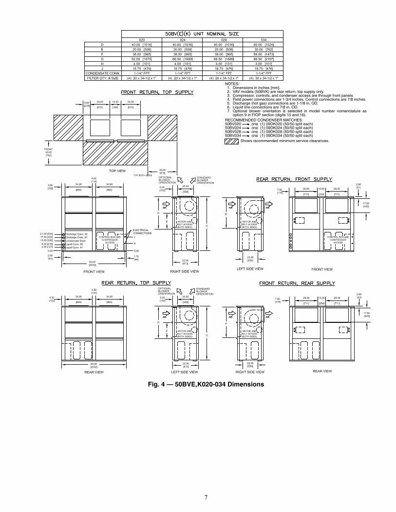
Fig. 4 — 50BVE,K020-034 Dimensions
NOTES:1. Dimensions in inches [mm].2. VAV models (50BVK) are rear return, top supply only.3. Compressor, controls, and condenser access are through front panels.4. Field power connections are 1-3/4inches. Control connections are 7/8inches5. Discharge (hot gas) connections are 1-1/8 in. OD.6. Liquid line connections are 7/8 in. OD.7. Optional blower orientation is selected in model number nomenclature as
option 9 in FIOP section (digits 15 and 16).RECOMMENDED CONDENSER MATCHES:50BV020 one (1) 09DK020 (50/50 split each)50BV024 one (1) 09DK024 (50/50 split each)50BV028 one (1) 09DK028 (50/50 split each)50BV034 one (1) 09DK034 (50/50 split each)
Shows recommended minimum service clearances.
a50-8200

8
REAR VIEWRETURN AIR VIEW
LEFT SIDE VIEW
80.00
FRONT VIEW
54.38
8.75
15.00
13.00
31.00
BLOWERSECTIONACCESS
EVAPORATORACCESS
2.88 2.00
EVAPORATORACCESS
BLOWERSECTIONACCESS
LEFT SIDE VIEW
FILTER ACCESS
ECONO COIL (Optional)DIRECT EXPANSIONEVAPORATOR
REHEAT COIL (Optional)
STANDARDDISCHARGE
REAR DISCHARGE(Optional)
WATER IN(ECONO COIL OPTIONAL)
ELECTRICAL
81.50
BLOWERSECTIONACCESS
COMPRESSORACCESS
COMPRESSORACCESS
EVAPORATORACCESS
EVAPORATORACCESS
ELECTRICAL BOXACCESS
ELECTRICAL BOX
23.7518.75
49.75
21.75
9.88
111.00
3.19
5.50
65.50
54.75
2.00
23.255.00
51.63
1.50 1.50
LIFTING SUPPORT RAIL
69.50SHIPPING SECTION
10.75
3.75
BAC
Da50-8201
NOTES:1. Dimensions in inches.2. All units are rear return airflow configuration.3. Constant volume units are available with front or rear air supply4. VAV units (50BVW) are available with rear supply only.5. Recommended minimum service clearances are as follows:
a. Front and rear — 30 in. (762 mm)b. Left or right side — 65 in. (1651 mm) for coil removalc. Side opposite coil removal — 20 in. (508 mm)
CONNECTIONS
REPLACEMENT FILTERS : EIGHT (8) AT 17 x 27 x 4 INCHES.
A WATER OUT 2-1/2 in. FPT
B WATER IN 2-1/2 in. FPT
C CONDENSATE DRAIN 1-1/4 in. FPT
D ECONOMIZER DRAIN 1-1/4 in. FPT
Fig. 5 — 50BVT,V,W034 (High-Boy) Dimensions

9
Fig. 6 — 50BVT,V,W034 (Low-Boy) Dimensions
a50-8202
NOTES:1. Dimensions in inches.2. All units are rear return airflow configuration.3. Recommended minimum service clearances are as follows:
a. Front and rear — 30 in. (762 mm)b. Left or right side — 65 in. (1651 mm) for coil removalc. Side opposite coil removal — 20 in. (508 mm)
CONNECTIONS
REPLACEMENT FILTERS : EIGHT (8) AT 17 x 27 x 4 INCHES.
A WATER OUT 2-1/2 in. FPT
B WATER IN 2-1/2 in. FPT
C CONDENSATE DRAIN 1-1/4 in. FPT
D ECONOMIZER DRAIN 1-1/4 in. FPT
a50-8202.eps
10
REAR VIEWRETURN AIR VIEW
LEFT SIDE VIEW
80.00
FRONT VIEW
54.38
8.75
15.00
13.00
31.00
COMPRESSORACCESS
EVAPORATORACCESS
EVAPORATORACCESS
ELECTRICAL BOXACCESS
COMPRESSORACCESS
BLOWERSECTIONACCESS
BLOWERSECTIONACCESS
EVAPORATORACCESS
ELECTRICAL BOX
2.88
21.75
49.75
2.00
EVAPORATORACCESS
BLOWERSECTIONACCESS
LEFT SIDE VIEW
FILTER ACCESS
ECONO COIL (OPTIONAL)
DIRECT EXPANSIONEVAPORATOR
REHEAT COIL (OPTIONAL)
STANDARDDISCHARGE
REAR DISCHARGE(OPTIONAL)
WATER IN(ECONO COIL OPTIONAL)
ELECTRICAL
81.50
BLOWERSECTIONACCESS
COMPRESSORACCESS
COMPRESSORACCESS
EVAPORATORACCESS
EVAPORATORACCESS
ELECTRICAL BOXACCESS
ELECTRICAL BOX
139.00
23.7518.75
49.75
21.75
9.8819.759.88
111.00
3.19
5.50
65.50 65.504.00
54.75
2.00 2.00
23.255.00
51.63
1.50 1.50
LIFTING SUPPORT RAIL
69.50SHIPPING SECTION
69.50SHIPPING SECTION
10.75
3.75
ABC
D
NOTES:1. Dimensions in inches.2. All units are rear return airflow configuration.3. CV units are available with front or rear air supply4. VAV units (50BVW) are available with rear supply only.5. Recommended minimum service clearances are as follows:
a. Front and rear — 30 in. (762 mm)b. Left and right sides — 65 in. (1651 mm) for coil removal
CONNECTIONS
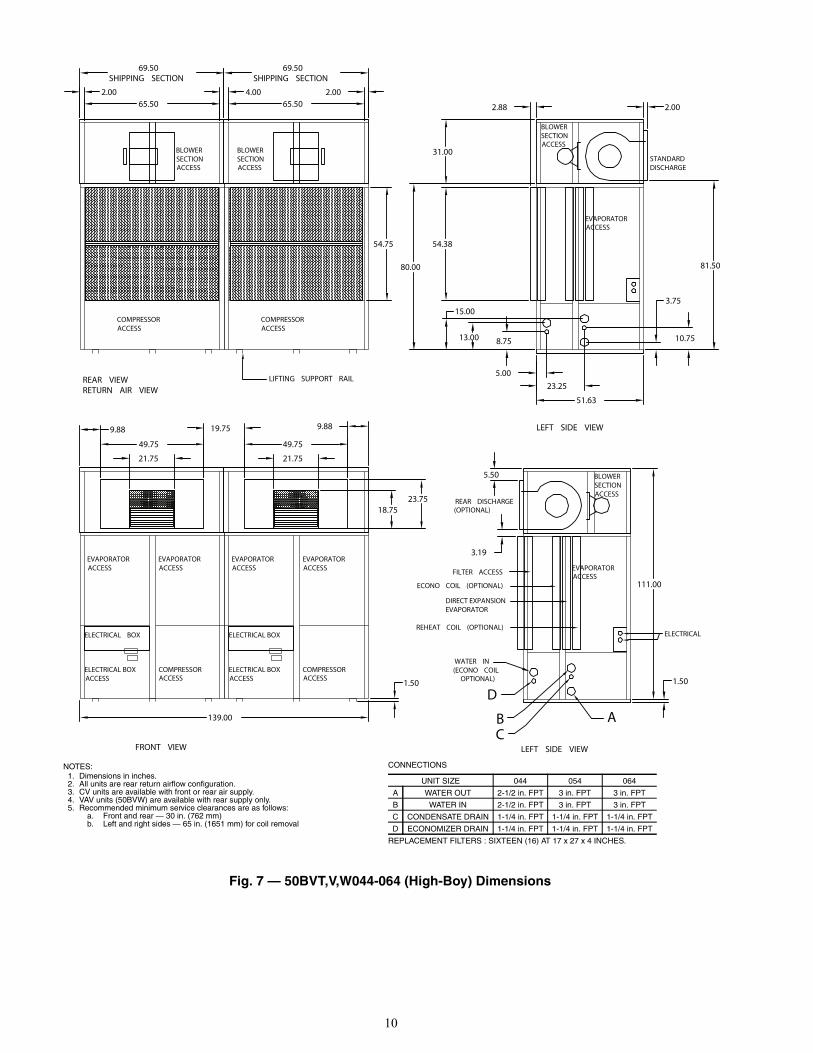
REPLACEMENT FILTERS : SIXTEEN (16) AT 17 x 27 x 4 INCHES.
UNIT SIZE 044 054 064
A WATER OUT 2-1/2 in. FPT 3 in. FPT 3 in. FPT
B WATER IN 2-1/2 in. FPT 3 in. FPT 3 in. FPT
C CONDENSATE DRAIN 1-1/4 in. FPT 1-1/4 in. FPT 1-1/4 in. FPT
D ECONOMIZER DRAIN 1-1/4 in. FPT 1-1/4 in. FPT 1-1/4 in. FPT
a50-8203
Fig. 7 — 50BVT,V,W044-064 (High-Boy) Dimensions
11
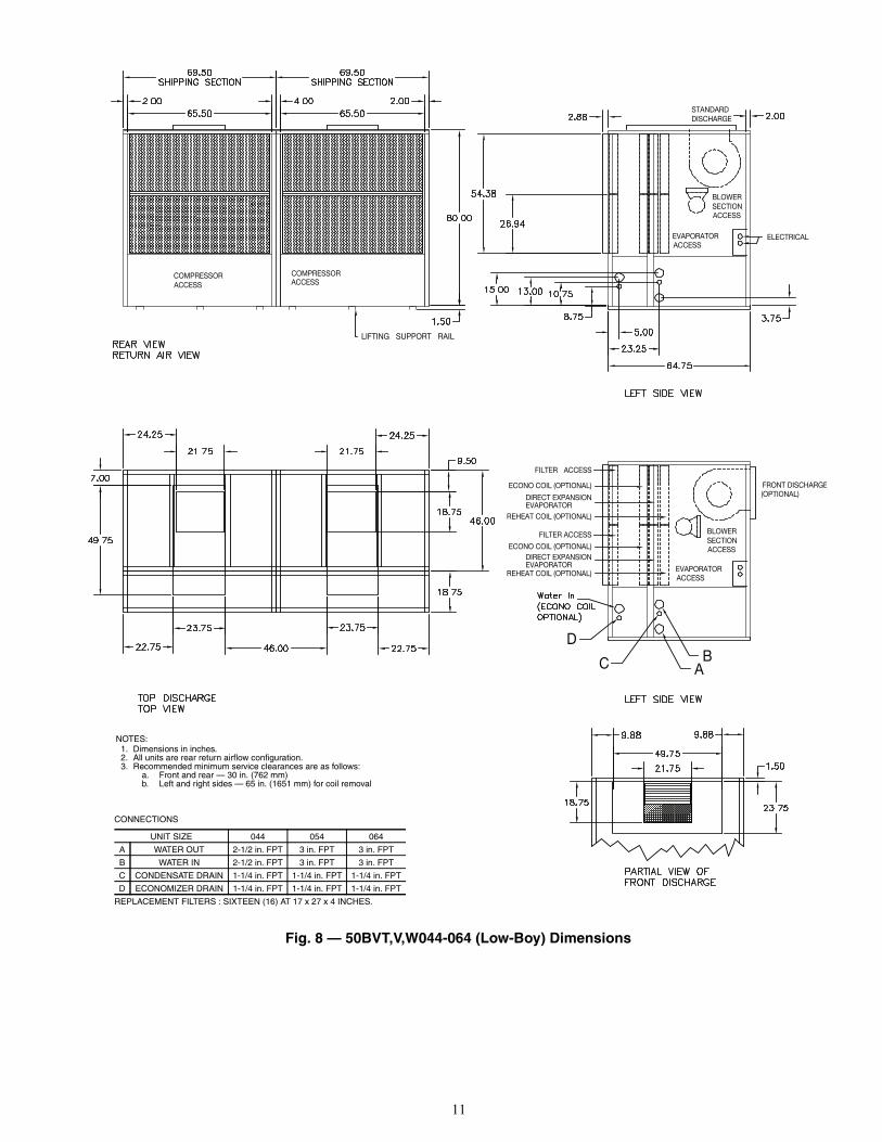
Fig. 8 — 50BVT,V,W044-064 (Low-Boy) Dimensions
CONNECTIONS
REPLACEMENT FILTERS : SIXTEEN (16) AT 17 x 27 x 4 INCHES.
UNIT SIZE 044 054 064
A WATER OUT 2-1/2 in. FPT 3 in. FPT 3 in. FPT
B WATER IN 2-1/2 in. FPT 3 in. FPT 3 in. FPT
C CONDENSATE DRAIN 1-1/4 in. FPT 1-1/4 in. FPT 1-1/4 in. FPT
D ECONOMIZER DRAIN 1-1/4 in. FPT 1-1/4 in. FPT 1-1/4 in. FPT
NOTES:1. Dimensions in inches.2. All units are rear return airflow configuration.3. Recommended minimum service clearances are as follows:
a. Front and rear — 30 in. (762 mm)b. Left and right sides — 65 in. (1651 mm) for coil removal
a50-8204

12
REAR VIEWRETURN AIR VIEW
LEFT SIDE VIEW
80.00
FRONT VIEW
54.38
8.7513.00
31.00
BLOWERSECTIONACCESS
EVAPORATORACCESS
2.88 2.00
EVAPORATORACCESS
BLOWERSECTIONACCESS
LEFT SIDE VIEW
FILTER ACCESS
ECONO COIL (Optional)
DIRECT EXPANSIONEVAPORATOR
REHEAT COIL (Optional)
STANDARDDISCHARGE
REAR DISCHARGE(Optional)
WATER IN(ECONO COIL OPTIONAL)
ELECTRICAL
81.50
BLOWERSECTIONACCESS
COMPRESSORACCESS
COMPRESSORACCESS
EVAPORATORACCESS
EVAPORATORACCESS
ELECTRICAL BOXACCESS
ELECTRICAL BOX
23.7518.75
49.75
21.75
9.88
111.00
3.19
5.50
65.50
54.75
2.00
23.255.00
51.63
1.50 1.50
LIFTING SUPPORT RAIL
69.50SHIPPING SECTION
10.75
E
F
ABCD
NOTES:1. Dimensions in inches.2. All units are rear return airflow configuration.3. Constant volume units are available with front or rear air supply4. VAV units (50BVX) are available with rear supply only.5. Recommended condenser match is ONE (1) 09DK034 (50/50 split).6. Use proper piping practice for remote refrigerant connections. Refer to
Carrier System Design Manual Part 3.7. Recommended minimum service clearances are as follows:
a. Front and rear — 30 in. (762 mm)b. Left or right side — 65 in. (1651 mm) for coil removalc. Side opposite coil removal — 20 in. (508 mm)
CONNECTIONS
REPLACEMENT FILTERS : EIGHT (8) AT 17 x 27 x 4 INCHES.
A LIQUID LINE CIRCUIT 1 7/8 in. OD
B LIQUID LINE CIRCUIT 2 7/8 in. OD
C DISCHARGE LINE CIRCUIT 1 1-1/8 in. OD
D DISCHARGE LINE CIRCUIT 2 1-1/8 in. OD
E CONDENSATE DRAIN 1-1/4 in. FPT
F ECONOMIZER DRAIN 1-1/4 in. FPT
a50-8205
Fig. 9 — 50BVU,X034 (High-Boy) Dimensions

13
a50-8206
Fig. 10 — 50BVU,X034 (Low-Boy) Dimensions
NOTES:1. Dimensions in inches.2. All units are rear return airflow configuration.3. Recommended condenser match is ONE (1) 09DK034 (50/50 split).4. Use proper piping practice for remote refrigerant connections. Refer to
Carrier System Design Manual Part 3.5. Recommended minimum service clearances are as follows:
a. Front and rear — 30 in. (762 mm)b. Left or right side — 65 in. (1651 mm) for coil removalc. Side opposite coil removal — 20 in. (508 mm)
CONNECTIONS
REPLACEMENT FILTERS : EIGHT (8) AT 17 x 27 x 4 INCHES.
A LIQUID LINE CIRCUIT 1 7/8 in. OD
B LIQUID LINE CIRCUIT 2 7/8 in. OD
C DISCHARGE LINE CIRCUIT 1 1-1/8 in. OD
D DISCHARGE LINE CIRCUIT 2 1-1/8 in. OD
E CONDENSATE DRAIN 1-1/4 in. FPT
F ECONOMIZER DRAIN 1-1/4 in. FPT
a50-8206

14
REAR VIEWRETURN AIR VIEW
LEFT SIDE VIEW
80.00
FRONT VIEW
54.38
8.7513.00
31.00
COMPRESSORACCESS
EVAPORATORACCESS
EVAPORATORACCESS
ELECTRICAL BOXACCESS
COMPRESSORACCESS
BLOWERSECTIONACCESS
BLOWERSECTIONACCESS
EVAPORATORACCESS
ELECTRICAL BOX
2.88
21.75
49.75
2.00
EVAPORATORACCESS
BLOWERSECTIONACCESS
LEFT SIDE VIEW
FILTER ACCESS
ECONO COIL (OPTIONAL)
DIRECT EXPANSIONEVAPORATOR
REHEAT COIL (OPTIONAL)
STANDARDDISCHARGE
REAR DISCHARGE(OPTIONAL)
WATER IN(ECONO COIL OPTIONAL)
ELECTRICAL
81.50
BLOWERSECTIONACCESS
COMPRESSORACCESS
COMPRESSORACCESS
EVAPORATORACCESS
EVAPORATORACCESS
ELECTRICAL BOXACCESS
ELECTRICAL BOX
139.00
23.7518.75
49.75
21.75
9.8819.759.88
111.00
3.19
5.50
65.50 65.504.00
54.75
2.00 2.00
23.255.00
51.63
1.50 1.50
LIFTING SUPPORT RAIL
69.50SHIPPING SECTION
69.50SHIPPING SECTION
10.75
E
F
ABCD
ABCD
Fig. 11 — 50BVU,X044-064 (High-Boy) Dimensions
NOTES:1. Dimensions in inches.2. All units are rear return airflow configuration.3. CV units are available with front or rear air supply4. VAV units (50BVX) are available with rear supply only.5. Use proper piping practice for remote refrigerant connections. Refer to
Carrier System Design Manual Part 3.6. Recommended minimum service clearances are as follows:
a. Front and rear — 30 in. (762 mm)b. Left and right sides — 65 in. (1651 mm) for coil removal
CONNECTIONS
REPLACEMENT FILTERS : SIXTEEN (16) AT 17 x 27 x 4 INCHES.
UNIT SIZE 044 054 064
A LIQUID LINE CIRCUIT 1, 2 7/8 in. OD 7/8 in. OD 7/8 in. OD
B LIQUID LINE CIRCUIT 3, 4 7/8 in. OD 7/8 in. OD 7/8 in. OD
C DISCHARGE LINE CIRCUIT 1, 2 1-1/8 in. OD 1-1/8 in. OD 1-1/8 in. OD
D DISCHARGE LINE CIRCUIT 3, 4 1-1/8 in. OD 1-1/8 in. OD 1-1/8 in. OD
E CONDENSATE DRAIN 1-1/4 in. FPT 1-1/4 in. FPT 1-1/4 in. FPT
F ECONOMIZER DRAIN 1-1/4 in. FPT 1-1/4 in. FPT 1-1/4 in. FPTa50-8207

15
a50-8208
NOTES:1. Dimensions in inches.2. All units are rear return airflow configuration.3. Use proper piping practice for remote refrigerant connections. Refer to
Carrier System Design Manual Part 3.4. Recommended minimum service clearances are as follows:
a. Front and rear — 30 in. (762 mm)b. Left and right sides — 65 in. (1651 mm) for coil removal
CONNECTIONS
REPLACEMENT FILTERS : SIXTEEN (16) AT 17 x 27 x 4 INCHES.
UNIT SIZE 044 054 064
A LIQUID LINE CIRCUIT 1, 2 7/8 in. OD 7/8 in. OD 7/8 in. OD
B LIQUID LINE CIRCUIT 3, 4 7/8 in. OD 7/8 in. OD 7/8 in. OD
C DISCHARGE LINE CIRCUIT 1, 2 1-1/8 in. OD 1-1/8 in. OD 1-1/8 in. OD
D DISCHARGE LINE CIRCUIT 3, 4 1-1/8 in. OD 1-1/8 in. OD 1-1/8 in. OD
E CONDENSATE DRAIN 1-1/4 in. FPT 1-1/4 in. FPT 1-1/4 in. FPT
F ECONOMIZER DRAIN 1-1/4 in. FPT 1-1/4 in. FPT 1-1/4 in. FPT
Fig. 12 — 50BVU,X044-064 (Low-Boy) Dimensions

16
Fig. 13 — 50BVC,J,Q020-028 with Optional Waterside Economizer Dimensions
NOTES:1. Dimensions in inches [mm].2. Refer to base unit certified drawing for additional unit dimensions, service
clearance, and alternate airflow configurations.
a50-7306ef

17
Fig. 14 — 50BVC,J,Q034 with Optional Waterside Economizer Dimensions
NOTES:1. Dimensions in inches [mm].2. Refer to base unit certified drawing for additional unit dimensions, service
clearances, and alternate airflow configurations.
a50-7307ef

18
Table 2A — Physical Data — 50BVC,E,J,K,Q
LEGEND *R-410A models.
UNIT 50BVC,E,J,K,Q 020 024 028 034NOMINAL CAPACITY (Tons) 18 20 25 30OPERATING WEIGHT (lb)
50BVC,Q…50BVJ 1192…1227 1378…1413 1428…1473 1680…172550BVE…50BVK 1110…1145 1290…1325 1320…1365 1520…1565
COMPRESSOR Copeland ScrollQuantity 2 2 2 2Number of Refrigerant Circuits 2 2 2 2Oil (oz) Ckt 1…Ckt 2 85…85 110…110 110…110 140…140
REFRIGERANT TYPE R-22 or R-410AExpansion Device TXV TXV TXV TXVOperating Charge (lb) Ckt 1…Ckt 2 8.1…8.1 9.1…9.1 9.1…9.1 18.0…18.0
CONDENSER (50BVC,Q,J only) Tube-in-Tube CoaxialQuantity of Manifolded Circuits 2 2 2 2Nominal Flow Rate (gpm) 54 60 75 90Water Flow Range (gpm) 36-72 40-80 50-100 60-120Max Water Working Pressure (psig) 400 400 400 400Max Refrig. Working Pressure (psig) 450 (600*) 450 (600*) 450 (600*) 450 (600*)Min Entering Water Temp (F) 50 50 50 50Max Entering Water Temp (F) 110 110 110 110Waterside Volume (gal) 3.6 4.0 5.0 6.0
EVAPORATOR COILRows…Fins/in. 3…14 3…14 3…14 3…14Total Face Area (sq ft) 18.1 18.1 18.1 22.0
EVAPORATOR FANQuantity…Size 2…15x15 2…15x15 2…15x15 2…15x15Type Drive Belt Belt Belt BeltNominal cfm 7200 8000 10,000 12,000Std Motor Qty…hp…Frame Size 2…1.5…56 2…2…56H 2…3…56HZ 2…5…56HZAlt 1 Motor Qty…hp…Frame Size 2…2…56H 2…3…56HZ 2…5…56HZ —Alt 2 Motor Qty…hp…Frame Size 2…3…56HZ 2…5…56HZ — —Alt 3 Motor Qty…hp…Frame Size 2…5…56HZ — — —Motor Nominal rpm (1.5, 2, 3, hp) 1725 1725 1725 —Motor Nominal rpm (5 hp) 3450 3450 3450 3450Fan Drive rpm Range
Std Fan Drive (1.5, 2, 3 hp) 753-952 753-952 753-952 —Std Fan Drive (5 hp) 967-1290 967-1290 967-1290 967-1290Med Static Fan Drive (1.5, 2, 3 hp) 872-1071 872-1071 872-1071 —
Motor Bearing Type Ball Ball Ball BallMaximum Allowable rpm 1300 1300 1300 1300Motor Pulley Pitch Diameter
Std Fan Drive (1.5, 2, 3 hp) 3.7-4.7 3.7-4.7 3.7-4.7 —Std Fan Drive (5 hp) 2.9-3.9 2.9-3.9 2.9-3.9 2.9-3.9Med Static Fan Drive (1.5, 2, 3 hp) 4.3-5.3 4.3-5.3 4.3-5.3 —
Motor Shaft Diameter (in.) (1.5, 2 hp) 5/8 5/8 — —Motor Shaft Diameter (in.) (3, 5 hp) 7/8 7/8 7/8 7/8Belt, Qty…Type…Length (in.)
Std Fan Drive (1.5, 2 hp) 1…B…39 1…B…39 — —Std Fan Drive (3 hp) 2…B…39 2…B…39 2…B…39 —Std Fan Drive (5 hp) 2...BX…42 2...BX…42 2...BX…42 2...BX…42Med Static Fan Drive (1.5, 2 hp) 1…B…40 1…B…40 — —Med Static Fan Drive (3 hp) 2…B…40 2…B…40 2…B…40 —
Pulley Center Line Distance (in.) 10.1…10.9 10.1…10.9 10.1…10.9 10.1…10.9Speed Change Per Full Turn of
Moveable Pulley Flange (rpm)Std Fan Drive (1.5, 2, 3 hp) 33 33 33 —Std Fan Drive (5 hp) 54 54 54 54Med Static Fan Drive (1.5, 2, 3 hp) 33 33 33 —
Fan Shaft Diameter (in.) 1 1 1 1HIGH PRESSURE SWITCHES (psig)
Cutout 380 (420*) ± 10 380 (420*) ± 10 380 (420*) ± 10 380 (420*) ± 10Reset (Auto) 300 (420*) ± 15 300 (420*) ± 15 300 (420*) ± 15 300 (420*) ± 15
LOW PRESSURE SWITCHES (psig)Cutout 20 (40*) ± 3 20 (40*) ± 3 20 (40*) ± 3 20 (40*) ± 3Reset (Auto) 40 (60*) ± 5 40 (60*) ± 5 40 (60*) ± 5 40 (60*) ± 5
REMOTE REFRIGERANT CONNECTIONS (50BVE,K Only)Discharge (Hot Gas) Connection (in.) Qty…Size 2…11/8 2…11/8 2…11/8 2…11/8Liquid Connection (in.) Qty…Size 2…7/8 2…7/8 2…7/8 2…7/8
RETURN AIR FILTERSQuantity…Size (in.) 4…20x34.5x1 4…20x34.5x1 4…20x34.5x1 4…30x34.5x1
TXV — Thermostatic Expansion Valve

19
Table 2B — Physical Data — 50BVT,U,V,W,X
UNIT 50BVT,U,V,W,X 034 044 054 064NOMINAL CAPACITY (Tons) 30 40 50 60OPERATING WEIGHT (lb)
50BVT,V…50BVW 2580…2645 4334…4404 5198…5298 5230…533050BVU…50BVX 2420…2485 4094…4164 4938…5038 4970…5070
COMPRESSOR Copeland ScrollQuantity 2 4 4 4Number of Refrigerant Circuits 2 4 4 4Oil (oz)
Circuit 1…Circuit 2 140…140 110…110 140…140 140…140Circuit 3…Circuit 4 — 110…110 140…140 140…140
REFRIGERANT TYPE R-22Expansion Device TXV TXV TXV TXVOperating Charge (lb)
Circuit 1…Circuit 2 18.0…18.0 10.0…10.0 18.0…18.0 18.0…18.0Circuit 3…Circuit 4 — 10.0…10.0 18.0…18.0 18.0…18.0
CONDENSER (50BVT,V,W only) Tube-in-Tube CoaxialQuantity of Manifolded Circuits 2 4 4 4Nominal Flow Rate (gpm) 90 120 150 180Water Flow Range (gpm) 60-120 80-160 100-200 120-240Max Water Working Pressure (psig) 400 400 400 400Max Refrig. Working Pressure (psig) 450 450 450 450Min Entering Water Temp (F) 50 50 50 50Max Entering Water Temp (F) 110 110 110 110Waterside Volume (gal) 6.0 9.0 11.3 13.5
EVAPORATOR COILRows…Fins/in. 4…12 3…12 4…12 4…12Total Face Area (sq ft) 23.2 46.4 46.4 46.4
EVAPORATOR FANQuantity…Size 1…18x18 2…18x18 2…18x18 2…18x18Type Drive Belt Belt Belt BeltNominal cfm 12,000 16,000 20,000 24,000Motor Option 1 Qty…hp…Frame Size 1…7.5…213T 2…7.5…213T 2…7.5…213T 2…7.5…213TMotor Option 2 Qty…hp…Frame Size 1…10…215T 2…10…215T 2…10…215T 2…10…215TMotor Option 3 Qty…hp…Frame Size 1…15…254T 2…15…254T 2…15…254T 2…15…254TMotor Option 4 Qty…hp…Frame Size 1…20…256T — 2…20…256T 2…20…256TMotor Nominal rpm 1750 1750 1750 1750Fan Drive RPM Range
Standard (7.5 hp) 780-960 780-960 780-960 780-960Standard (10, 15, 20 hp), Med Static (7.5 hp) 805-991 805-991 805-991 805-991Med Static (10, 15, 20 hp), High Static (7.5 hp) 960-1146 960-1146 960-1146 960-1146High Static (10, 15, 20 hp) 1119-1335 1119-1335 1119-1335 1119-1335
Motor Bearing Type Ball Ball Ball BallMaximum Allowable rpm 1450 1450 1450 1450Motor Pulley Pitch Diameter
Std Fan Drive (7.5 hp) 5.2-6.4 5.2-6.4 5.2-6.4 5.2-6.4Std Fan Drive (10, 15, 20 hp), Med Static (7.5 hp) 4.8-6.0 4.8-6.0 4.8-6.0 4.8-6.0Med Static Fan Drive (10, 15, 20 hp), High Static (7.5 hp) 5.8-7.0 5.8-7.0 5.8-7.0 5.8-7.0High Static Fan Drive (10, 15, 20 hp) 5.8-7.0 5.8-7.0 5.8-7.0 5.8-7.0
Motor Shaft Diameter (in.) (7.5, 10 hp) 13/8 13/8 13/8 13/8Motor Shaft Diameter (in.) (15, 20 hp) 15/8 15/8 15/8 15/8Belt, Qty…Type…Length (in.)
Std Fan Drive (7.5 hp) 2…B…48 2...B...48 2…B…48 2…B…48Std Fan Drive (10, 15, 20 hp), Med Static (7.5 hp) 2…B…46 2…B…46 2…B…46 2…B…46Med Static Fan Drive (10, 15, 20 hp), High Static 7.5 hp) 2…B…48 2…B…48 2…B…48 2…B…48High Static Fan Drive (10, 15, 20 hp) 2…B…45 2…B…45 2…B…45 2…B…45
Pulley Center Line Distance (in.) 10.2-11.4 10.2-11.4 10.2-11.4 10.2-11.4Speed Change Per Full Turn of Moveable Pulley Flange (rpm)
Std Fan Drive (7.5 hp) 36 36 36 36Std Fan Drive (10, 15, 20 hp), Med Static (7.5 hp) 31 31 31 31Med Static Fan Drive (10, 15, 20 hp), High Static (7.5 hp) 31 31 31 31High Static Fan Drive (10, 15, 20 hp) 36 36 36 36
Fan Shaft Diameter (in.) 17/16 17/16 17/16 17/16
HIGH PRESSURE SWITCHES (psig)Cutout 380 ± 10 380 ± 10 380 ± 10 380 ± 10Reset (Auto) 300 ± 15 300 ± 15 300 ± 15 300 ± 15
LOW PRESSURE SWITCHES (psig)Cutout 20 ± 3 20 ± 3 20 ± 3 20 ± 3Reset (Auto) 40 ± 5 40 ± 5 40 ± 5 40 ± 5
REMOTE REFRIGERANT CONNECTIONS (50BVU,X Only)Discharge (Hot Gas) Connection (in.) Qty…Size 2…11/8 4…11/8 4…11/8 4…11/8Liquid Connection (in.) Qty…Size 2…7/8 4…7/8 4…7/8 4…7/8
RETURN AIR FILTERSQuantity…Size (in.) 8…17x27x4 16…17x27x4 16…17x27x4 16…17x27x4

20
Step 3 — Install Ductwork — The VAV units mustuse a “pair of pants” configuration as shown in Fig. 15. Referto the Carrier System Design Manual or ASHRAE (AmericanSociety of Heating, Refrigerating and Air Conditioning Engi-neers) standards for the recommended duct connection to unitwith 2 fans.
A supply air outlet collar and return air duct flange areprovided on all units to facilitate duct connections. Refer todimensional drawings (Fig. 3-14) for connection sizes andlocations.
A flexible canvas duct connector is recommended on bothsupply and return air sides of the units to be connected to thesystem ductwork.
All metal ductwork should be adequately insulated to avoidheat loss or gain and to prevent condensation from forming onthe duct walls. Uninsulated ductwork is not recommended, asthe unit's performance will be adversely affected.
Do not connect discharge ducts directly to the bloweroutlet(s). The factory filter should be left in place on a freereturn system.
If the unit will be installed in a new installation, the ductsystem should be designed in accordance with the System De-sign Manual, Part 2 and with ASHRAE (American Society ofHeating, Refrigeration and Air Conditioning Engineers) proce-dures for duct sizing. If the unit will be connected to an existingduct system, check that the existing duct system has the capaci-ty to handle the required airflow for the unit application at anacceptable system static pressure. If the existing duct system istoo small, larger ductwork must be installed.
The duct system and diffusers should be sized to handle thedesign airflow volumes quietly. To maximize sound attenuation
of the unit's blower(s), the supply and return air plenums shouldbe insulated for a length of at least 15 ft from the unit. Direct lineof sight from return air grilles into the unit's return should beavoided. If return air is to be ducted to an equipment room, anelbow should be installed within the equipment room. Running areturn air drop to near the floor of the room will aid in soundattenuation. Avoid transmitting vibrations generated by themovement of air in the ducting to the walls of the building. Thisis especially important where ductwork penetrates walls. Themaximum recommended return air velocity is 1,000 fpm. Lowerreturn air velocities will result in lower sound power levels. Theuse of round supply duct plenums should be considered, as itwill significantly reduce low frequency sound at the equipmentroom. If rectangular supply plenums are used, the aspect ratio ofthe duct should be kept as small as possible (i.e., as close tosquare as possible). The large, flat surface areas associated withlarge aspect ratio duct systems will transmit sound to the space,and the potential for duct-generated noise is increased. The max-imum recommended supply air duct velocity is 2,000 fpm.
Units with two fans should have a properly designed “pairof pants” duct connection. An adequate straight length ofducting from the unit should be allowed before elbows areinstalled. If connecting an elbow directly to the fan outlet, aminimum straight length of 2 fan diameters from the fan outletis recommended. Elbows should turn in the direction of fan ro-tation, if possible. Abrupt turns will generate air turbulence andexcessive noise. Turning vanes should be used in all short radi-us bends. Ensure that ducting does not obstruct access to theunit for routine servicing.DUCT STATIC PRESSURE PROBE AND TUBING (VAVOnly) — On VAV systems, the duct static pressure sensor andtubing are field-mounted. The sensor tubing sensing pointshould be located near the end of the main supply trunk duct ina position free from turbulence effects and at least 10 duct di-ameters downstream and 4 duct diameters upstream from anymajor transitions or branch take-offs. Incorrectly placing thesensing point could result in improper operation of the entireVAV system.
Install the factory-supplied duct static pressure probe withthe tip facing into the airflow. See Fig. 16.
Use 1/4-in. OD approved polyethylene tubing for up to50 ft (3/8-in. OD for 50 to 100 ft) to connect the probe to thebulkhead fitting mounted above the unit display panel(Fig. 17). Carefully route the tubing from the probe to thisbulkhead fitting.
The static pressure control should be adjusted so that, at fullairflow, all of the remote VAV terminal boxes receive theminimum static pressure required plus any downstream resis-tance. Control the system to the lowest static pressure set pointthat will satisfy airflow requirements. Lower static pressure setpoints reduce total required brake horsepower and reducegenerated sound levels.
Fig. 15 — Typical Fan Discharge Connections for Multiple Fan Units
AB
a50-8357.eps
NOTE: A = 11/2 to 21/2B
AIRFLOW
PROBE
TUBING
Fig. 16 — Duct Static Pressure Probe (P/N 39EK20462)
a50-7138ef

21
DUCT HIGH-STATIC (DHS) LIMIT SWITCH (VAVOnly) — The duct high static limit switch is a mechanicalsafety that prevents duct overpressurization. The switch is lo-cated on the side of the VAV low voltage control panel(Fig. 18) and is factory set at 3 in. wg. To make an adjustmentusing an accurate differential pressure gage, connect low sideand high side to gage and pressure source. Place a voltmeteracross common and normally open contacts. Rotate the adjust-ment knob (Fig. 19) clockwise to increase pressure setting andcounterclockwise to decrease pressure setting. When the bot-tom of the adjustment knob is approximately 1/8-in. from theswitch body, the switch will trip at approximately 3 in. wg.
Step 4 — Make Piping ConnectionsCONDENSER WATER PIPING (Water-Cooled Only) —Always follow national and local codes when installing waterpiping to ensure a safe and proper installation. Connections tothe unit should incorporate vibration eliminators to reducenoise and vibration to the building, and shutoff valves to facili-tate servicing.
Prior to connecting the unit(s) to the condenser watersystem, the system should be flushed to remove foreignmaterial that could cause condenser fouling. Install a screenstrainer with a minimum of 20 mesh ahead of the condenserinlet to prevent condenser fouling and internal condenser tubedamage from foreign material.
Supply and return water piping must be at least as large asthe unit connections, and larger for long runs. Refer to theSystem Design Manual, Part 3, and standard piping practice,when sizing, planning, and routing water piping. See dimen-sion drawings (Fig. 3-14) for water connection sizes andlocations.
Units are furnished standard with a copper heat exchanger.A cupronickel heat exchanger is also available as afactory-installed option. Copper is adequate for closed loopsystems where good quality water is available. In conditionswhere scale formation or water treatment is questionable, theoptional cupronickel heat exchanger should be used. Where thewater is especially corrosive or could lead to excessive fouling,intermediate plate frame heat exchangers are recommended.
The unit is capable of operating with entering water temper-atures as low as 50 F, without the need for head pressurecontrol. If the entering water temperature is expected to belower, or more stable unit operation is desired, a field-suppliedwater-regulating valve may be used.
IMPORTANT: Use tubing that complies with local codes.Improper location or installation of the supply duct pres-sure tubing will result in unsatisfactory unit operation andpoor performance.
WARNING ALARM
REMOTE
LOCAL
OFF
ENTER
CLEAR
SRVC
HIST ALGO
TESTALRM
3
6
9
1 2
4 5
7 8
0 .–
STAT
SET SCHD
EXPN
EDIT
WARNING ALARM
REMOTE
LOCAL
OFF
ENTER
CLEAR
SRVC
HIST ALGO
TESTALRM
3
6
9
1 2
4 5
7 8
0 .–
STAT
SET SCHD
EXPN
EDIT
DUCT STATICPRESSUREPROBEBULKHEADFITTING
Fig. 17 — Display Panel Location onUnit Front Panel
a50-7267efCAUTION
Galvanized pipe or fittings are not recommended with50BV units due to the possibility of galvanic corrosioncaused by dissimilar metals. When selecting pipingmaterials, use only approved piping materials that meetapplicable codes and that will handle the temperatures andpressures that may be experienced in the application.Piping systems will sweat if low temperature fluid is usedin the system. For these applications, supply and returnwater piping should be insulated to protect from condensa-tion damage. The minimum recommended entering watertemperature to the unit is 50 F.
Fig. 18 — DHS Limit Switch Location
a50-8253
Fig. 19 — DHS Limit Switch (P/N 190060)
a50-7268tf

22
This unit has multiple independent refrigerant circuits withseparate condensers. The individual condensers are manifoldedtogether on the waterside to provide easy, single-point waterconnections. In order to achieve proper head pressure controlwhen a water-regulating valve is used, a temperature-actuatedvalve is recommended. This allows any of the independentrefrigerant circuits to operate while still modulating condenserwater flow in response to loop water temperature.
A glycol solution should be used if ambient temperaturesare expected to fall below freezing or if the loop water temper-ature is below 50 F while operating in the reverse cycle heatingmode (heat pump units only). Refer to Table 3, whichlists freezing points of glycol at different concentrations. Aminimum concentration of 20% is recommended. Waterpressure drop will increase and unit performance will decreasewith increasing glycol concentrations.
Units with factory-installed waterside economizers havecooling water passing through the economizer and condenserin series while operating in the economizer mode. Duringnormal operation, water bypasses the economizer coil.
Table 3 — Glycol Freezing Points
All manual flow valves used in the system should be of theball valve design. Globe or gate valves must not be used due tohigh pressure drops and poor throttling characteristics.
Do not exceed recommended condenser fluid flow ratesshown in Tables 4A and 4B. Serious damage or erosion of theheat exchanger tubes could occur. Piping systems should notexceed 10 fps fluid velocities to ensure quietness and tube wallintegrity. Refer to Tables 4A and 4B for condenser water pres-sure drop versus flow rate. Flow rates outside of the publishedrange should not be used.
Table 4A — Condenser Pressure Drop50BVC,J,Q Units
Table 4B — Condenser Pressure Drop50BVT,V,W Units
Ball valves should be installed in the supply and return linesfor unit isolation and water flow balancing.
Pressure and temperature ports are recommended in boththe supply and return lines for system flow balancing. Theseopenings should be 5 to 10 pipe diameters from the unit waterconnections. For thorough mixing and temperature stabiliza-tion, wells in the water piping should extend at least 1/2 pipediameter into the pipe. Measuring the condenser watersidepressure drop and referring to Tables 4A and 4B can help toproperly set the water flow rate.
Improper fluid flow due to valving, piping, or improperpump operation constitutes abuse that may result in voiding ofunit warranty. The manufacturer will not be responsible fordamages or failures resulting from improper piping design orpiping material selection.EVAPORATOR CONDENSATE DRAIN — The conden-sate drain connection is 11/4-in. FPT and is located on the sameside of the unit as the condenser water connections. See dimen-sion drawings (Fig. 3-14) for exact location.
Drain lines should be pitched away from the unit with aminimum slope of 1/8-in. per foot and conform to all local andnational codes.
A trap must be installed in the condensate line to ensure freecondensate flow (units are not internally trapped). A vertical airvent is sometimes required to avoid air pockets.
Install a condensate-trapping drain line at the units drainconnection. See Fig. 20 for correct drain layout.
When calculating trap depth, remember that it is not thetotal static pressure but the upstream or downstream staticresistance that is trapped against. For instance, when calculat-ing the trap depth for a cooling coil condensate pan, trapagainst the coil pressure drop in that coil section and any otherpressure drops upstream of it.
If calculating the trap depth for the cooling coil, use the totalstatic pressure drop (coil plus any other components upstreamof it) plus 1 in. (P1 = negative static pressure + 1 in.), as shownin Fig. 20.
Traps must store enough condensate to prevent losing thedrain seal at start-up. The “Minimum 1/2 P1” dimension ensuresthat enough condensate is stored.
Drain pans should be cleaned periodically to avoid thebuild-up of dirt and bacterial growth.
% GLYCOLFREEZE POINT (° F)
Ethylene Glycol Proplylene Glycol20 18 1930 7 940 –7 –550 –28 –27
FLOW RATE(gpm)
SIZE 020 SIZE 024 SIZE 028 SIZE 034Pressure Drop (ft wg)
35 9.1 — — —40 11.2 6.0 — —45 13.5 7.5 — —50 15.9 9.1 9.1 —55 18.4 10.9 10.9 —60 21.1 12.8 12.8 10.865 23.9 14.8 14.9 12.770 27.4 17.0 17.2 14.775 — 19.3 19.6 16.980 — 21.7 22.2 19.285 — — 24.9 21.790 — — 27.8 24.395 — — 30.8 27.1
100 — — 34.0 30.0105 — — — 33.1110 — — — 36.3115 — — — 39.7120 — — — 43.2
FLOW RATE(gpm)
SIZE 034 SIZE 044 SIZE 054 SIZE 064Pressure Drop (ft wg)
60 8.7 — — —70 11.9 — — —80 15.5 6.3 — —90 19.6 8.0 — —
100 24.2 9.9 6.0 —110 29.3 12.0 7.3 —120 34.9 14.3 8.7 8.7130 — 16.7 10.2 10.2140 — 19.4 11.8 11.8150 — 22.3 13.6 13.6160 — 25.3 15.5 15.5170 — — 17.4 17.4180 — — 19.6 19.6190 — — 21.8 21.8200 — — 24.2 24.2210 — — — 26.6220 — — — 29.2230 — — — 31.9240 — — — 34.8

23
HOT WATER HEATING COIL (Optional) — A factory-installed one or 2-row hot water heating coil is available as an op-tion. The coil is supplied with hot water from a boiler through sep-arate piping from the condenser water loop. All controls for heat-ing operation are field-supplied.
Piping should be in accordance with accepted industrystandards and all components rated for the system pressureexpected. Pipe the coils so that they will drain, and provide adrain and vent.
Always connect the supply to the top of the coil, and thereturn to the bottom. Refer to Fig. 3-14 for hot water supplyand return piping locations.
Water coils should not be subjected to entering-air tempera-tures below 38 F to prevent coil freeze-up. If air temperaturesacross the coil are going to be below this value, use a glycol orbrine solution. Use a solution with the lowest concentrationthat will match the coldest air expected. Excess concentrationswill greatly reduce coil capacity.
The return air duct system should be carefully designed toget adequate mixing of the return air and outdoor air streams toprevent cold spots on the coil that could freeze.
A 2 or 3-way, field-supplied modulating control valve, or asimple two-position on-off valve may be used to control waterflow. Select the valve based on the control valve manufacturer'srecommendations for size and temperature rating. Select thecontrol valve CV based on pressure drop and flow rate throughthe coil. This information is available from the VPACBuildersoftware program or Tables 5A and 5B.
Pipe sizes should be selected based on the head pressureavailable from the pump. Water velocity should not exceed8 fps. Design the piping system for approximately 3 ft of lossper 100 equivalent ft of pipe. The piping system should allowfor expansion and minimize vibration between the unit andpiping system.
Table 5A — Hot Water Pressure Drop50BVC,E,J,K,Q Units
Table 5B — Hot Water Pressure Drop50BVT,U,V,W,X Units
WATER ECONOMIZER (Optional) — The optional watersideeconomizer (pre-cooling coil) is factory-installed and piped inter-nally, in series with the condenser water circuit (Fig. 21). A divert-ing valve and factory controls are included with the option. Onlyone set of field connections needs to be made for condenser waterand economizer water. In addition, when unit is shipped witheconomizer option, the economizer drain must be connected to aseparate trap. Follow the same steps for the economizer drain asdescribed for evaporator condensate drain. An Aquastat is used tomodulate water flow through the economizer. The controller ismounted to the low voltage control box. Electrical connections arefactory installed and wired. The remote bulb is shipped internal tothe unit and requires field mounting. Care should be taken not todent the bulb or miscalibration may occur. The Aquastat has atemperature range adjustment (–30 F to 100 F) and is field set. SeeFig. 3-14 for connection locations and sizes. See Tables 6A and6B for economizer waterside pressure drop data.
1/2
P1
P1
NOTE: P1 equals negative static pressure plus 1 inch.
Fig. 20 — Condensate Drain Layout
a39-2371efFLOW RATE
(gpm)SIZE 020 SIZE 024 SIZE 028 SIZE 034
Pressure Drop (ft wg)10 0.7 0.7 0.7 —15 1.5 1.5 1.5 —20 2.6 2.6 2.6 —25 4.0 4.0 4.0 —30 5.8 5.8 5.8 0.135 7.8 7.8 7.8 0.140 10.2 10.2 10.2 0.145 12.9 12.9 12.9 0.250 15.8 15.8 15.8 0.255 — — — 0.360 — — — 0.365 — — — 0.4
FLOW RATE (gpm)
SIZE 034 SIZE 044 SIZE 054 SIZE 064Pressure Drop (ft wg)
45 2.4 — — —50 3.0 — — —55 3.6 — — —60 4.3 — — —65 5.0 — — —70 5.7 — — —75 6.6 — — —80 7.4 — — —85 8.4 — — —90 9.3 2.5 2.5 2.5
100 — 3.1 3.1 3.1110 — 3.7 3.7 3.7120 — 4.4 4.4 4.4130 — 5.1 5.1 5.1140 — 5.9 5.9 5.9150 — 6.7 6.7 6.7160 — 7.6 7.6 7.6170 — 8.6 8.6 8.6180 — 9.6 9.6 9.6
FLUID IN
N.O.
AQUASTATMBV
“BULB STRAPPEDTO FLUID” IN LINE(FIELD INSTALLED)
N.O.
N.C.
3-WAY MOTORIZEDBALL VALVE
WATERSIDEECONOMIZER
COIL
FLUID TO REFRIGERANTHEAT EXCHANGER
POSITIVE SHUT-OFF SOLENOIDVALVE FOR VARIABLE SPEEDPUMPING SYSTEM(FIELD INSTALLED)
a50-7269ef
Fig. 21 — Optional Water Economizer

24
The waterside economizer can also be ordered withoutfactory-installed piping or controls. This offers additionalflexibility for specific applications. In this case, the coil isfactory mounted, but all supply and return piping and controlsare field supplied.
Table 6A — Economizer Pressure Drop Curve(ft wg), 50BVC,E,J,K,Q Units
Table 6B — Economizer Pressure Drop Curve(ft wg), 50BVT,U,V,W,X Units
REMOTE REFRIGERANT PIPING (Remote Air-CooledOnly) — Carrier 50BVE,K,U,X units are supplied withoutcondensers. To complete the installation, these units must befield connected to a suitable remote condenser. The 50BV unitsfrom 18 to 30 tons contain 2 equally sized independent refriger-ant circuits. Units from 40 to 60 tons have 4 separate equal ca-pacity refrigerant circuits. It is important that the condenser cir-cuiting be properly matched to the 50BV unit circuiting. Other-wise, unsatisfactory operation will result. Carrier will not beresponsible for improperly matched remote condenser selec-tions. Recommended condenser matches are shown in Table 7.
Table 7 — Recommended Condenser Matches for 50BVE,K,U,X Units
Install the air-cooled condenser or condensers according tothe installation instructions provided with the condenser(s).Connection locations and sizes for the hot gas and liquid lineson the 50BV units are shown in Fig. 3-14, 22 and 23. For50BV units up to 30 tons, there will be 2 hot gas lines and 2 liq-uid lines to install between the unit and the condenser. Above30 tons, 4 hot gas lines and 4 liquid lines will be installed be-tween the unit and the 2 condensers. Refer to the System De-sign Manual, Part 3 for standard refrigerant piping techniques.Also see the air-cooled condenser installation instructions foradditional guidance.
Remote air-cooled 50BV units (only) are shipped with a drynitrogen holding charge. After refrigerant connections aremade, release nitrogen, evacuate, leak test, and charge thesystem as described in Charging the System in the Mainte-nance section of this manual.
FLOW RATE (gpm)
SIZE 020 SIZE 024 SIZE 028 SIZE 034Pressure Drop (ft wg)
35 8.9 — — —40 11.5 11.0 — —45 14.4 13.8 — —50 17.6 16.9 16.9 —55 21.1 20.4 20.4 —60 24.9 24.1 24.1 3.565 29.0 28.1 28.2 4.170 34.4 32.5 32.5 4.775 — 37.1 37.2 5.480 — 42.1 42.1 6.185 — — 47.4 6.990 — — 52.9 7.795 — — 58.7 8.5
100 — — 64.9 9.4105 — — — 10.3110 — — — 11.3115 — — — 12.3120 — — — 13.4
FLOW RATE (gpm)
SIZE 034 SIZE 044 SIZE 054 SIZE 064Pressure Drop (ft wg)
60 13.1 — — —70 17.9 — — —80 23.5 5.8 — —90 29.8 7.3 — —
100 36.9 9.1 9.0 —110 44.8 11.0 11.0 —120 53.4 13.1 13.1 13.1130 — 15.4 15.4 15.4140 — 17.9 17.9 17.9150 — 20.6 20.6 20.6160 — 23.5 23.5 23.5170 — — 26.6 26.5180 — — 29.8 29.8190 — — 33.3 33.2200 — — 36.9 36.8210 — — — 40.7220 — — — 44.7230 — — — 48.9240 — — — 53.3
50BV NO. OFCKTS CONDENSER(S) CONDENSER
CIRCUITING020 2 09DK020 (1) or 09AW020 (1) 50/50%024 2 09DK024 (1) or 09AW020 (1) 50/50%028 2 09DK028 (1) or 09AW025 (1) 50/50%034 2 09DK034 (1) or 09AW030 (1) 50/50%044 4 09DK024 (2) or 09AW020 (2) 50/50% (each)054 4 09DK028 (2) or 09AW025 (2) 50/50% (each)064 4 09DK034 (2) or 09AW030 (2) 50/50% (each)
LIQUIDLINE
SLOPETOWARDCONDENSER
TRAP (MUST BEABOVE TOP OFCONDENSER COIL)
REMOTECONDENSER
HOT GASLINE
50BVUNIT
Fig. 22 — System with CondenserAbove Evaporator
a50-7270ef
50BVUNIT
REMOTECONDENSER
HOT GASLINE
LIQUIDLINE
SLOPE TOWARDCONDENSER
a50-7271ef
Fig. 23 — System with Evaporator Above Condenser

25
Step 5 — Complete Electrical Connections —Verify that electrical requirements listed on the unit nameplatematch available power supply. The unit voltage must be withinthe range shown in Tables 8A and 8B and phases must bebalanced within 2%. Contact the local power company for linevoltage corrections. Never operate a motor where a phase im-balance in supply voltage is greater than 2%.
For an unbalanced 3-phase supply voltage, use the follow-ing formula to determine the percent of voltage imbalance:Percent Voltage Imbalance
Example: Supply voltage is 460-3-60.AB = 452 VBC = 464 VAC = 455 V
Determine maximum deviation from average voltage:(AB) 457 – 452 = 5 V(BC) 464 – 457 = 7 V (AC) 457 – 455 = 2 V
Table 8A — Electrical Data — 50BVC,E,J,K,Q
LEGEND
= 100 xmax voltage deviation from average voltage
average voltage
Average Voltage =452 + 464 + 455
3
=1371
3 = 457
UNIT SIZE50BVC,E,J,K,Q
NOMINAL VOLTAGE
(3 Ph, 60 Hz)
VOLTAGE RANGE
COMPRESSORINDOOR FAN MOTOR POWER
SUPPLYDISCONNECT
SIZENo. 1 No. 2
Min Max RLA LRA RLA LRA Qty HP (ea)
FLA (ea) MCA MOCP FLA
020
208/230 187 253 32.9 195 32.9 195 2
1.5 5.0 84.0 110 75.82 6.4 86.8 110 78.63 9.0 92.0 110 83.85 12.2 98.4 110 90.2
460 414 506 16.5 95 16.5 95 2
1.5 2.5 42.1 50 38.02 3.2 43.5 50 39.43 4.5 46.1 50 42.05 6.1 49.3 50 45.2
575 518 633 13.6 80 13.6 80 2
1.5 2.0 34.6 45 31.22 2.0 34.6 45 31.23 3.6 37.8 45 34.45 5.4 41.4 45 38.0
024
208/230 187 253 33.6 225 33.6 225 22 6.4 88.4 120 80.03 9.0 93.6 120 85.25 12.2 100.0 120 91.6
460 414 506 18.6 114 18.6 114 22 3.2 48.3 60 43.63 4.5 50.85 60 46.25 6.1 54.05 60 49.4
575 518 633 13.6 80 13.6 80 22 2.0 34.6 45 31.23 3.6 37.8 45 34.45 5.4 41.4 45 38.0
028
208/230 187 253 53.6 245 53.6 245 23 9.0 138.6 190 125.25 12.2 145.0 190 131.6
460 414 506 20.7 125 20.7 125 23 4.5 55.6 70 50.45 6.1 58.8 70 53.6
575 518 633 16.4 100 16.4 100 23 3.6 44.1 60 40.05 5.4 47.7 60 43.6
034208/230 187 253 59.1 425 59.1 425 2 5 12.2 157.4 200 142.6
460 414 506 26.4 187 26.4 187 2 5 6.1 71.6 90 65.0575 518 633 20.5 148 20.5 148 2 5 5.4 56.9 70 51.8
FLA — Full Load AmpsHP — HorsepowerLRA — Locked Rotor AmpsMCA — Minimum Circuit AmpsMOCP — Maximum Overcurrent ProtectionRLA — Rated Load Amps
Maximum deviation is 7 V.Determine percent of voltage imbalance:% Voltage Imbalance = 100 x
= 1.53%This amount of phase imbalance is satisfactory as it is below
the maximum allowable 2%.
POWER WIRING — Properly sized fuses or HACR (Heat-ing, Air Conditioning and Refrigeration) circuit breakers mustbe installed for branch circuit protection, according to thenational and applicable local codes. See unit nameplate andTables 8A and 8B for maximum overcurrent protection size.
These units are provided with single point, main powersupply terminal blocks. Refer to Fig. 3-14 for conduit connec-tion locations. Connect the power leads as indicated on the unitwiring diagrams (found in the Troubleshooting section) and becertain to connect the ground lead to the ground lug in the unithigh voltage electrical box. Refer to Tables 8A and 8B for unitelectrical data.
IMPORTANT: If supply voltage phase imbalance ismore than 2%, contact the local electric utility com-pany immediately.
7457

26
Table 8B — Electrical Data — 50BVT,U,V,W,X
LEGEND
UNIT SIZE50BVT,U,V,W,X
NOMINAL VOLTAGE
(3 Ph, 60 Hz)
VOLTAGE RANGE
COMPRESSORINDOOR FAN MOTOR POWER
SUPPLYDISCONNECT
SIZENo. 1 / No. 2 No. 3 / No. 4
Min Max RLA LRA RLA LRA Qty HP (ea)
FLA (ea) MCA MOCP FLA
034
208/230 187 253 62.2 376 — — 1
7.5 19.4 159.4 200 143.810 25.8 165.8 225 150.215 38.6 178.6 225 163.020 49.6 189.6 250 174.0
460 414 506 27.6 178 — — 1
7.5 9.7 71.8 90 64.910 12.9 75.0 100 68.115 19.3 81.4 100 74.520 24.8 86.9 110 80.0
575 518 633 20.5 148 — — 1
7.5 7.8 53.9 70 48.810 10.3 56.4 70 51.315 15.4 61.5 80 56.420 19.8 65.9 80 60.8
044
208/230 187 253 42.0 239 42.0 239 27.5 19.4 217.3 250 206.810 25.8 230.1 250 219.615 38.6 255.7 250 245.2
460 414 506 19.2 125 19.2 125 27.5 9.7 101.0 110 96.210 12.9 107.4 125 102.615 19.3 120.2 125 115.4
575 518 633 12.4 80 12.4 80 27.5 7.8 68.3 80 65.210 10.3 73.3 80 70.215 15.4 83.5 90 80.4
054
208/230 187 253 47.1 318 47.1 318 2
7.5 19.4 239.0 250 227.210 25.8 251.8 250 240.015 38.6 277.4 300 265.620 49.6 299.4 300 287.6
460 414 506 22.6 158 22.6 158 2
7.5 9.7 115.5 125 109.810 12.9 121.9 125 116.215 19.3 134.7 150 129.020 24.8 145.7 150 140.0
575 518 633 17.3 125 17.3 125 2
7.5 7.8 89.1 100 84.810 10.3 94.1 110 89.815 15.4 104.3 110 100.020 19.8 113.1 125 108.8
064
208/230 187 253 62.2 376 62.2 376 2
7.5 19.4 303.2 350 287.610 25.8 316.0 350 300.415 38.6 341.6 400 326.020 49.6 363.6 400 348.0
460 414 506 27.6 178 27.6 178 2
7.5 9.7 136.7 150 129.810 12.9 143.1 150 136.215 19.3 155.9 150 149.020 24.8 166.9 175 160.0
575 518 633 20.5 148 20.5 148 2
7.5 7.8 102.7 110 97.610 10.3 107.7 125 102.615 15.4 117.9 125 112.820 19.8 126.7 125 121.6
FLA — Full Load Amps MCA — Minimum Circuit AmpsHP — Horsepower MOCP — Maximum Overcurrent ProtectionLRA — Locked Rotor Amps RLA — Rated Load Amps

27
Modular Units — For units with multiple main air-conditioning sections, connect the high voltage compressorpower wiring to the line side of the high voltage terminal blockin the second section’s high voltage electrical box. This wiringis located in the upper portion of the compressor compartment.
Connect the low voltage wiring, located in the compressorcompartment, between the two air-conditioning sections usingthe quick connects provided.
For the supply fan motor, connect the 3-phase high voltagewiring, coiled behind the high voltage panel, to the line side ofthe supply fan motor terminal block located in the fan compart-ment. For VAV units, connect the 3-phase high voltage wiringto the line side of VFD.
For units with multiple fans, connect the control powerwiring with the quick connects provided at the fan compart-ment junction.CONTROL WIRING (CV Only) — A standard commercialthermostat controls constant volume units. These units turncompressors on or off in response to zone temperature. The50BV units provide 2 stages of cooling.50BVC,E,Q020-034 and 50BVT,U,V034 Only — Thesemodels have 2 independent refrigerant circuits, each capable ofbeing staged independently. Thermostat wiring is connected tothe 6-position low voltage terminal block located in the unitelectrical box. The 50BV units have a 24-vac control trans-former, which provides power to the control circuit and to thethermostat. The thermostat connections and their functions areas follows:
C Transformer 24-vac CommonO Reversing Valve (heat pumps only)Y1 1st Stage Compressor ContactorY2 2nd Stage Compressor ContactorR Transformer 24-vac HotG Indoor Fan ContactorSelect an appropriate commercial thermostat that has 2 stag-
es of cooling control. If the unit is a heat pump, make sure thethermostat is capable of heat pump control. Any of theDebonair® series commercial thermostats will meet the re-quirements, and are available in a variety of attractive styles, inprogrammable and non-programmable versions.
Install the thermostat in the space where the temperature isbeing controlled, according to the instructions provided withthe thermostat.
To wire the thermostat:1. Connect the ‘C’ terminal from the 50BV unit to the ‘C’
terminal on the thermostat.2. Wire the ‘Y1’ and ‘Y2’ terminals from the 50BV unit
to the ‘Y1’ and ‘Y2’ terminals, respectively, at thethermostat.
3. Make a connection between the ‘G’ terminal on the unitand the ‘G’ terminal on the thermostat.
4. Attach a wire from the ‘R’ terminal at the unit to the ‘R’terminal at the thermostat.
5. 50BVQ and 50BVV ONLY: If the unit is a heat pump,connect a final wire from terminal ‘O’ on the heat pumpunit to the ‘W1/O/B’ terminal at the thermostat.Configure the thermostat for heat pump operation usingthe installation instructions provided with the thermostat.Set the reversing valve polarity of the thermostat to ‘O’.
See Fig. 24 for typical thermostat wiring.
50BVT,U,V044-064 Only — Units larger than 30 tons have 4independent refrigerant circuits.
These units can be controlled using a standard commercial,2-stage thermostat. In this case, the first stage of cooling willturn on compressors 1 and 2, and the second stage will turn oncompressors 3 and 4. It is also possible to have 4 stages of cool-ing, using a suitable field-supplied control method.
For 2-stage thermostat wiring, refer to Fig. 25. Jumpersmust be installed between the G and O terminals in Modules Aand B. A field-supplied, 24-v pilot relay should be used to en-ergize Y2 on Module B whenever Y1 is energized on ModuleA. Similarly, a field-supplied 24-v pilot relay should be in-stalled to energize Y4 on Module B whenever Y3 on ModuleA is energized (Y2 stage of thermostat calls for cooling).
Finally, verify that transformer phasing is consistentbetween Modules A and B.REMOTE CONDENSER FAN CONTACTOR WIR-ING — For units up to 30 tons, one remote condenser isrequired. Install a field-supplied 24-v pilot relay (Aux relay)between Y1 and C. This will energize the FC contactor on theremote condenser whenever there is a call for cooling.
For 40 to 60 ton units, 2 remote condensers are required. Besure to make piping connections so that compressors 1 and 2 areconnected to condenser 1, and compressors 3 and 4 are connect-ed to condenser 2. Use an additional set of NO (normally open)contacts on PR1 to energize FC1 on condenser 1, and a set ofNO contacts on PR2 to energize FC1 on condenser 2.CONTROL WIRING (VAV Only) — The VAV units are de-signed to operate either with a building management system orstand alone (local control).Carrier Comfort Network® Control Wiring — The CC6400Control Module connects to the Carrier Comfort Network(CCN) bus in a daisy chain arrangement. Negative pins oneach component must be connected to respective negative pinsand likewise positive pins on each component must beconnected to respective positive pins. The controller signal pinsmust be wired to the signal ground pins. Wiring connectionsfor CCN must be made at the 3-pin plug.
At any baud rate (9600, 19200, 38400 baud), the number ofcontrollers is limited to 239 devices maximum. Bus length maynot exceed 4000 ft, with no more than 60 total devices on any1000-ft section. Optically isolated RS-485 repeaters arerequired every 1000 ft.NOTE: Carrier device default is 9600 baud.
The CCN communication bus wiring is field supplied andfield installed. It consists of shielded 3-conductor cable withdrain (ground) wire. The cable selected must be identical to theCCN communication bus wire used for the entire network. SeeTable 9 for cable recommendations.
WARNING
Before wiring the thermostat to the unit, make sure thatmain power to the unit has been disconnected. Failure toheed this warning could result in personal injury.
TYPICAL UNIT
C
G
Y1
O
R
Y2
24 VAC COMMON
FAN RELAY
COMPRESSOR RELAY
HEAT PUMP
24 VAC RETURN
2nd STAGE COMPRESSOR RELAY
Y2 R W1 Y1 G C
THERMOSTATBO
Fig. 24 — Typical Wiring 18 to 30 Ton Units (Two-Stage Cooling Units)
a50-7272ef

28
Table 9 — Recommended Cables
NOTE: Conductors and drain wire must be at least 20 AWG(American Wire Gage), stranded, and tinned copper. Individualconductors must be insulated with PVC, PVC/nylon, vinyl,Teflon®*, or polyethylene. An aluminum/polyester 100% foilshield and an outer jacket of PVC, PVC/nylon, chrome vinyl,or Teflon with a minimum operating temperature range of–20 C to 60 C is required.
The communication bus shields must be tied together ateach system element. If the communication bus is entirelywithin one building, the resulting continuous shield must beconnected to ground at only one single point. If the communi-cation bus cable exits from one building and enters anotherbuilding, the shields must be connected to the grounds at alightning suppressor in each building (one point only). Wiring Control Devices — Standard controls require no fieldwiring.
Standard controls for VAV applications include: duct staticpressure (DSP), duct high static limit switch (DHS), compres-sor status (CSMUX), supply fan start/stop (SF), and supply fanspeed (SPEED).
Field-installed devices and the factory-supplied supply airtemperature sensor (required) will be wired to the field termi-nal block (TB2) provided. Refer to Fig. 26 and the followingdescriptions. This terminal is located in the control panel asshown in Fig. 27 and 28.
SUPPLY AIR TEMPERATURE SENSOR (SAT) — Thesupply air temperature sensor (Fig. 29) is used to measure thetemperature of the air leaving the unit. The sensor should belocated in the supply air duct, about 1 ft from the unit dischargeconnection (Fig. 30). On units with 2 fans, locate the sensor ap-proximately 5 duct diameters downstream from “pair of pants”duct connection, allowing for adequate mixing of supply air.
Mount the sensor as follows:1. Remove the cover of the sensor junction box.2. Drill a 7/16-in. hole at the selected location.3. Install the sensor through the hole and secure using 2
no. 8 screws (provided). Do not overtighten.4. Connect the sensor to the control box. Use an 18 or
20 AWG, 2 conductor, twisted pair cable. This cable issuitable for distances of up to 500 feet.
Connect the field wires to the supply air sensor using wirenuts or closed end style crimp connectors. Do not cut thesensor leads. Use the full length of lead supplied on the sensor.
In the control box, remove the jacket from the cable. Routethe sensor wires over to the right hand side of the field terminalblock (TB2). Strip the insulation back about 1/4-in. from eachconductor. Connect the two wires to terminals 101 and 102(SAT) on the terminal board. Polarity is not a consideration.See Table 10 for resistance vs. temperature values.
C O Y1 Y3 R G C O Y2 Y4
C O Y1 Y2 R G
PR2
PR1
PR1
PR2
FIELD-SUPPLIED THERMOSTAT
UNIT MODULE ‘A’ UNIT MODULE ‘B’
Remote Condenser Units Only
PR1
PR2
FC1-4 FC1-5
FC1-4 FC1-5
(#1)
(#2)
R G
Fig. 25 — Typical Wiring 40 to 60 Ton Units (Two-Stage Cooling)
a50-7273ef
LEGENDFC — Fan ContactorPR — Pilot Relay
MANUFACTURER PART NUMBERAlpha 2413 or 5463
American A22503Belden 8772
Columbia 02525
*Teflon is a registered trademark of E.I. du Pont de Nemours andCompany.
Fig. 26 — Field Terminal Block
a50-7164tf
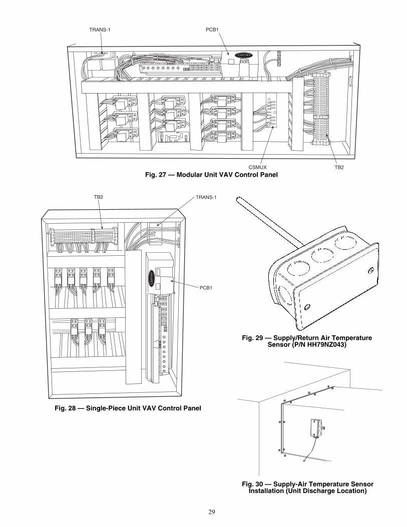
29
TRANS-1 PCB1
TB2CSMUX
PCB1
TB2 TRANS-1
Fig. 27 — Modular Unit VAV Control Panel
Fig. 28 — Single-Piece Unit VAV Control Panel
Fig. 29 — Supply/Return Air TemperatureSensor (P/N HH79NZ043)
Fig. 30 — Supply-Air Temperature SensorInstallation (Unit Discharge Location)
a50-7275ef
a50-7276ef
a39-1867t
39-312d

30
Table 10 — Thermistor Resistance vs Temperature Values for Supply-Air Temperature Sensor
(10 kilo-ohm)
SMOKE DETECTOR/FIRE ALARM SHUTDOWN(FSD) — To allow a smoke detector to shut the 50BV unitdown, remove the jumper from FSD to C and wire these termi-nals to a set of normally closed contacts on the smoke detector.ALARM (ALARM) AND WARNING (WARN) OUT-PUTS — Two dry contacts output a discrete signal when thealarm and warning lights on the display are lit. To pick up thealarm output signal, wire between the ALARM and ALM-CMterminals. To pick up the warning output signal, wire betweenthe WARN and ALM-CM terminals.REMOTE OCCUPANCY (ROCC) — The 50BV unit maybe commanded by another control system or a twist timer tobecome occupied and run when a set of dry contacts close. Inorder for this to occur, wire the contacts to ROCC and C andset the Local/Off/Remote switch to REMOTE.RETURN AIR TEMPERATURE SENSOR (RAS) — Thereturn/mixed air temperature sensor is a 5 kilo-ohm tempera-ture sensor used as the space control point. For every degreethat the RAS is below the set point, the supply air set point willbe reset by the configured value in the custom configuredRESET RATIO. Refer to Table 11 and Fig. 31.
Table 11 — Thermistor Resistance vs Temperature Values for Return-Air Temperature
Sensor (5 kilo-ohm)
Wire the sensor to PCB1 connector J3, terminals 15 and 16.Change custom configuration as instructed in Configure theCustom Programming Selections section. Changing this con-figuration to YES changes the EWT input to be used as returnair temperature input.
START-UP
General — Complete the Start-Up Checklist on page CL-1before attempting system start-up.CRANKCASE HEATERS — The 50BVT,U,V,W,X034-064 units include crankcase heaters. Crankcase heaters are en-ergized as long as there is power to the unit and the compres-sor is not operating.
Wait 24 hours before starting the compressors to permitwarming by the crankcase heaters.
AFTER 24 hours, continue with the procedures below.CONFIRM THE INPUT POWER PHASE SEQUENCE —The input power phase rotation sequence must be L1-L2-L3 =ABC (or forward or clockwise) as indicated with a phaserotation meter. Incorrect input phase rotation will cause the com-pressors to rotate in reverse, which results in no cooling capacity.
If the compressor is rotating in the wrong direction, it may:emit increased noise; shut down due to internal overloadprotection; have only a small decrease in suction pressure whenit starts; or have only a small increase in discharge pressurewhen it starts. Also, no cooling will be produced at the
TEMP TEMP RESISTANCE(C) (F) (Ohms)–40 –40 335,651–35 –31 242,195–30 –22 176,683–25 –13 130,243–20 –4 96,974–15 5 72,895–10 14 55,298
–5 23 42,3150 32 32,6515 41 25,395
10 50 19,90315 59 15,71420 68 12,49425 77 10,00030 86 8,05635 95 6,53040 104 5,32545 113 4,36750 122 3,60155 131 2,98560 140 2,48765 149 2,08270 158 1,752
TEMP TEMP RESISTANCE(C) (F) (Ohms)–40 –40 167,835–35 –31 121,098–30 –22 88,340–25 –13 65,121–20 –4 48,487–15 5 36,447–10 14 27,648
–5 23 21,1570 32 16,3255 41 12,697
10 50 9,95215 59 7,85720 68 6,24725 77 5,00030 86 4,02835 95 3,26540 104 2,66245 113 2,18350 122 1,80155 131 1,49360 140 1,24465 149 1,04170 158 87675 167 74080 176 628
IMPORTANT: On VAV units, fan rotation directioncan NOT be used for the phase sequence check; fanrotation for VAV units with a variable speed drive isindependent of the unit input wiring sequence.
NOTE: All dimensions are in inches.
Fig. 31 — Return Air Temperature Sensor(P/N HH79NZ079)
a50-7274ef
1.00
8.00
0.811.25
0.220.25
0.50
2.25
65º
O0.187 O0.187(2 HOLES)

31
evaporator. If any of these conditions occurs, refer to theService section to correct the compressor rotation beforecontinuing.INTERNAL WIRING — Check all electrical connections inunit control boxes; tighten as required.RETURN-AIR FILTERS — Check that correct filters areinstalled in filter tracks (see Tables 2A and 2B). Do not operateunit without return-air filters.COMPRESSOR MOUNTING — Compressors are internal-ly spring mounted. Do not loosen or remove compressor hold-down bolts.REFRIGERANT SERVICE PORTS — Each refrigerant systemhas a total of 2 Schrader-type service gage ports per circuit. Oneport is located on the suction line, and one on the compressordischarge line. Be sure that caps on the ports are tight.
CV Unit Start-UpEVAPORATOR FAN — Fan belt and variable pitch motorpulleys are factory installed. See Tables 12-19 for fan perfor-mance data. Be sure that fans rotate in the proper direction.
COOLING — Set the space thermostat to OFF position. Turnon unit power. Set space thermostat to COOL and the fan toAUTO. Adjust the thermostat temperature setting below roomtemperature. Compressor 1 starts on closure of contactor (com-pressors 1 and 2 on 4-circuit units with 2-stage thermostat).
Adjust the thermostat to an even lower setting until the ther-mostat energizes Y2 (the second cooling stage). Compressor 2starts on closure of contactor (compressors 3 and 4 on 4-circuitunits with 2-stage thermostat).
Adjust the thermostat temperature to a setting just belowroom temperature. The second stage of cooling should turn off.
Set the thermostat temperature above room temperature. Allcompressors and the unit fan should now be off.HEATING (Heat Pump Units Only) — Follow the same se-quence as for cooling (above), except set the space thermostatto HEAT, and instead of adjusting the thermostat below roomtemperature, adjust it above. Verify that the compressors turnon and the unit runs in reverse cycle mode.
Set the thermostat below room temperature and confirmthat the compressors and fan turn off.
Table 12 — Fan Performance — 50BVC,E,Q020
LEGEND
NOTES:1. Units are available with the following motor and drive combina-
tions: 1.5, 2, 3, 5 hp standard drive; 1.5, 2, 3 hp medium staticdrive.For 1.5, 2, 3 hp standard drives, the drive range is 753 to952 rpm. For medium static drives, the drive range is 872 to1071 rpm. For 5 hp standard drives, the drive range is 967 to1290 rpm.
2. Italics indicates field-supplied drive required.3. Do not operate in shaded area.4. Static pressure losses must be applied to external static pres-
sure before entering the fan performance table.5. Interpolation is permitted, extrapolation is not.6. Fan performance is based on filter, unit casing and wet coil
losses.7. Bhp values are per fan. Watts values are per motor. Unit has
2 supply fans and 2 motors.
AIRFLOW (cfm)
AVAILABLE EXTERNAL STATIC PRESSURE (in. wg)0.2 0.4 0.6 0.8 1.0
Rpm Watts Bhp Rpm Watts Bhp Rpm Watts Bhp Rpm Watts Bhp Rpm Watts Bhp4500 — — — — — — 623 459 0.52 — — — — — —5000 — — — — — — 638 545 0.61 — — — — — —5500 — — — — — — 655 641 0.72 725 755 0.85 — — —6000 — — — 608 641 0.72 676 755 0.85 742 878 0.99 807 1001 1.136500 — — — 636 755 0.85 699 878 0.99 761 1010 1.14 821 1142 1.297000 604 774 0.87 666 906 1.02 726 1029 1.16 784 1170 1.32 841 1311 1.487500 634 916 1.03 693 1057 1.19 750 1189 1.34 805 1330 1.50 858 1480 1.678000 667 1085 1.22 723 1226 1.38 777 1377 1.55 829 1526 1.72 880 1676 1.898500 700 1273 1.43 753 1423 1.60 804 1573 1.77 853 1732 1.95 902 1836 2.139000 735 1480 1.67 785 1638 1.84 833 1745 2.02 881 1908 2.21 927 2071 2.40
AIRFLOW (cfm)
AVAILABLE EXTERNAL STATIC PRESSURE (in. wg)1.2 1.4 1.6 1.8 2.0
Rpm Watts Bhp Rpm Watts Bhp Rpm Watts Bhp Rpm Watts Bhp Rpm Watts Bhp4500 — — — — — — — — — — — — — — —5000 — — — — — — — — — — — — — — —5500 — — — — — — — — — — — — — — —6000 — — — — — — — — — — — — — — —6500 881 1283 1.44 — — — — — — — — — — — —7000 897 1451 1.63 951 1601 1.80 — — — — — — — — —7500 911 1629 1.83 963 1727 2.00 1014 1881 2.18 — — — — — —8000 930 1781 2.07 979 1935 2.24 1028 2098 2.43 1076 2260 2.62 1124 2422 2.818500 950 1989 2.31 997 2152 2.50 1043 2323 2.69 1089 2485 2.88 1134 2697 3.099000 973 2233 2.59 1018 2404 2.79 1062 2576 2.99 1106 2779 3.18 1149 2960 3.39
Bhp — Brake Horsepower Input to Supply FanWatts — Input Power to Supply Fan Motor
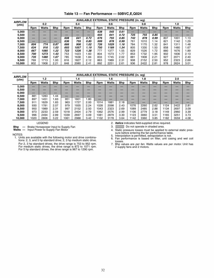
32
Table 13 — Fan Performance — 50BVC,E,Q024
LEGEND
NOTES:1. Units are available with the following motor and drive combina-
tions: 2, 3, and 5 hp standard drive; 2, 3 hp medium static drive.For 2, 3 hp standard drives, the drive range is 753 to 952 rpm.For medium static drives, the drive range is 872 to 1071 rpm.For 5 hp standard drives, the drive range is 967 to 1290 rpm.
2. Italics indicates field-supplied drive required.3. Do not operate in shaded area.4. Static pressure losses must be applied to external static pres-
sure before entering the fan performance table.5. Interpolation is permitted, extrapolation is not.6. Fan performance is based on filter, unit casing and wet coil
losses.7. Bhp values are per fan. Watts values are per motor. Unit has
2 supply fans and 2 motors.
AIRFLOW (cfm)
AVAILABLE EXTERNAL STATIC PRESSURE (in. wg)0.2 0.4 0.6 0.8 1.0
Rpm Watts Bhp Rpm Watts Bhp Rpm Watts Bhp Rpm Watts Bhp Rpm Watts Bhp5,000 — — — — — — 638 545 0.61 — — — — — —5,500 — — — — — — 655 641 0.72 725 755 0.85 — — —6,000 — — — 608 641 0.72 676 755 0.85 742 878 0.99 807 1001 1.136,500 — — — 636 755 0.85 699 878 0.99 761 1010 1.14 821 1142 1.297,000 604 774 0.87 666 906 1.02 726 1029 1.16 784 1170 1.32 841 1311 1.487,500 634 916 1.03 693 1057 1.19 750 1189 1.34 805 1330 1.50 858 1480 1.678,000 667 1085 1.22 723 1226 1.38 777 1377 1.55 829 1526 1.72 880 1676 1.898,500 700 1273 1.43 753 1423 1.60 804 1573 1.77 853 1732 1.95 902 1836 2.139,000 735 1480 1.67 785 1638 1.84 833 1745 2.02 881 1908 2.21 927 2071 2.409,500 769 1713 1.93 816 1827 2.12 863 1989 2.31 908 2152 2.50 952 2323 2.69
10,000 802 1908 2.21 848 2080 2.41 892 2251 2.61 936 2422 2.81 978 2624 3.01
AIRFLOW (cfm)
AVAILABLE EXTERNAL STATIC PRESSURE (in. wg)1.2 1.4 1.6 1.8 2.0
Rpm Watts Bhp Rpm Watts Bhp Rpm Watts Bhp Rpm Watts Bhp Rpm Watts Bhp5,000 — — — — — — — — — — — — — — —5,500 — — — — — — — — — — — — — — —6,000 — — — — — — — — — — — — — — —6,500 881 1283 1.44 — — — — — — — — — — — —7,000 897 1451 1.63 951 1601 1.80 — — — — — — — — —7,500 911 1629 1.83 963 1727 2.00 1014 1881 2.18 — — — — — —8,000 930 1781 2.07 979 1935 2.24 1028 2098 2.43 1076 2260 2.62 1124 2422 2.818,500 950 1989 2.31 997 2152 2.50 1043 2323 2.69 1089 2485 2.88 1134 2697 3.099,000 973 2233 2.59 1018 2404 2.79 1062 2576 2.99 1106 2779 3.18 1149 2960 3.399,500 996 2494 2.89 1039 2697 3.09 1081 2879 3.30 1123 3060 3.51 1165 3251 3.73
10,000 1020 2806 3.22 1061 2988 3.42 1102 3178 3.64 1142 3360 3.85 1182 3559 4.08
Bhp — Brake Horsepower Input to Supply FanWatts — Input Power to Supply Fan Motor

33
Table 14 — Fan Performance — 50BVC,E,Q028
LEGEND
NOTES:1. Units are available with 3 or 5 hp standard drive or 3 hp medium
static drive.For 3 hp standard drives, the drive range is 753 to 952 rpm. Formedium static drives, the drive range is 872 to 1071 rpm. 5 hpstandard drives have drive range of 967 to 1290 rpm.
2. Italics indicates field-supplied drive required.3. Do not operate in shaded area.4. Static pressure losses must be applied to external static pres-
sure before entering the fan performance table.5. Interpolation is permitted, extrapolation is not.6. Fan performance is based on filter, unit casing and wet coil
losses.7. Bhp values are per fan. Watts values are per motor. Unit has
2 supply fans and 2 motors.
AIRFLOW (cfm)
AVAILABLE EXTERNAL STATIC PRESSURE (in. wg)0.2 0.4 0.6 0.8 1.0
Rpm Watts Bhp Rpm Watts Bhp Rpm Watts Bhp Rpm Watts Bhp Rpm Watts Bhp6,250 — — — 624 678 0.79 689 797 0.92 753 917 1.06 815 1045 1.217,000 604 751 0.87 666 880 1.02 726 999 1.16 784 1136 1.32 841 1273 1.487,500 634 889 1.03 693 1027 1.19 750 1155 1.34 805 1291 1.50 858 1437 1.678,000 667 1054 1.22 723 1191 1.38 777 1337 1.55 829 1482 1.72 880 1627 1.898,500 700 1237 1.43 753 1382 1.60 804 1528 1.77 853 1682 1.95 902 1836 2.139,000 735 1437 1.67 785 1591 1.84 833 1745 2.02 881 1908 2.21 927 2071 2.409,500 769 1664 1.93 816 1827 2.12 863 1989 2.31 908 2152 2.50 952 2323 2.69
10,000 802 1908 2.21 848 2080 2.41 892 2251 2.61 936 2422 2.81 978 2624 3.0110,500 835 2179 2.53 879 2350 2.73 921 2531 2.93 963 2742 3.14 1004 2924 3.3511,000 870 2467 2.86 912 2688 3.08 952 2870 3.29 992 3060 3.51 1032 3251 3.7311,500 904 2824 3.24 944 3015 3.46 983 3206 3.67 1022 3405 3.90 1060 3605 4.1312,000 937 3169 3.63 976 3369 3.86 1014 3569 4.09 1051 3777 4.33 1088 3985 4.5712,500 972 3550 4.07 1010 3759 4.31 1046 3967 4.55 1082 4184 4.80 — — —
AIRFLOW (cfm)
AVAILABLE EXTERNAL STATIC PRESSURE (in. wg)1.2 1.4 1.6 1.8 2.0
Rpm Watts Bhp Rpm Watts Bhp Rpm Watts Bhp Rpm Watts Bhp Rpm Watts Bhp6,250 877 1173 1.36 — — — — — — — — — — — —7,000 897 1410 1.63 951 1555 1.80 — — — — — — — — —7,500 911 1582 1.83 963 1727 2.00 1014 1881 2.18 — — — — — —8,000 930 1781 2.07 979 1935 2.24 1028 2098 2.43 1076 2260 2.62 1124 2422 2.818,500 950 1989 2.31 997 2152 2.50 1043 2323 2.69 1089 2485 2.88 1134 2697 3.099,000 973 2233 2.59 1018 2404 2.79 1062 2576 2.99 1106 2779 3.18 1149 2960 3.399,500 996 2494 2.89 1039 2697 3.09 1081 2879 3.30 1123 3060 3.51 1165 3251 3.73
10,000 1020 2806 3.22 1061 2988 3.42 1102 3178 3.64 1142 3360 3.85 1182 3559 4.0810,500 1044 3106 3.56 1084 3296 3.78 1123 3496 4.01 1161 3686 4.23 1200 3886 4.4511,000 1070 3451 3.95 1109 3641 4.17 1146 3840 4.40 1184 4049 4.64 1220 4248 4.8711,500 1097 3804 4.36 1134 4012 4.60 1170 4221 4.84 1206 — — — — —12,000 1124 4193 4.81 — — — — — — — — — — — —12,500 — — — — — — — — — — — — — — —
Bhp — Brake Horsepower Input to Supply FanWatts — Input Power to Supply Fan Motor

34
Table 15 — Fan Performance — 50BVC,E,Q034
LEGEND
NOTES:1. Unit is available with 5 hp standard drive only. The drive range
is 967 to 1290 rpm.2. Italics indicates field-supplied drive required.
3. Do not operate in shaded area.4. Static pressure losses must be applied to external static pres-
sure before entering the fan performance table.5. Interpolation is permitted, extrapolation is not.6. Fan performance is based on filter, unit casing and wet coil
losses.7. Bhp values are per fan. Watts values are per motor. Unit has
2 supply fans and 2 motors.
AIRFLOW (cfm)
AVAILABLE EXTERNAL STATIC PRESSURE (in. wg)0.2 0.4 0.6 0.8 1.0
Rpm Watts Bhp Rpm Watts Bhp Rpm Watts Bhp Rpm Watts Bhp Rpm Watts Bhp9,000 639 1187 1.36 693 1334 1.53 745 1490 1.71 795 1646 1.89 843 1802 2.079,500 665 1362 1.56 717 1518 1.74 766 1674 1.92 814 1839 2.11 861 2004 2.30
10,000 693 1555 1.78 743 1720 1.97 791 1894 2.17 836 2058 2.36 881 2232 2.5610,500 721 1775 2.03 769 1949 2.23 815 2122 2.43 859 2296 2.63 902 2478 2.8411,000 749 2004 2.30 795 2186 2.51 840 2369 2.71 882 2551 2.92 924 2742 3.1411,500 777 2259 2.59 822 2451 2.81 864 2642 3.03 906 2833 3.25 946 3024 3.4712,000 805 2533 2.90 848 2733 3.13 889 2933 3.36 929 3133 3.59 968 3333 3.8212,500 835 2842 3.26 877 3042 3.49 917 3251 3.73 955 3460 3.97 993 3668 4.2013,000 865 3169 3.63 905 3378 3.87 944 3596 4.12 981 3813 4.37 1018 4021 4.6113,500 894 3514 4.03 933 3741 4.29 971 3958 4.54 1007 4184 4.80 — — —14,000 924 3895 4.46 961 4121 4.72 998 4356 4.99 — — — — — —
AIRFLOW (cfm)
AVAILABLE EXTERNAL STATIC PRESSURE (in. wg)1.2 1.4 1.6 1.8 2.0
Rpm Watts Bhp Rpm Watts Bhp Rpm Watts Bhp Rpm Watts Bhp Rpm Watts Bhp9,000 890 1958 2.24 936 2122 2.43 982 2296 2.63 1026 2460 2.82 1071 2642 3.039,500 906 2168 2.48 950 2341 2.68 994 2515 2.88 1037 2688 3.08 1079 2870 3.29
10,000 925 2405 2.76 967 2578 2.96 1009 2760 3.16 1051 2942 3.37 1092 3124 3.5810,500 944 2660 3.05 986 2842 3.26 1026 3024 3.47 1066 3215 3.68 1105 3405 3.9011,000 965 2924 3.35 1004 3115 3.57 1043 3315 3.80 1082 3505 4.02 1120 3705 4.2511,500 985 3224 3.69 1024 3414 3.91 1062 3614 4.14 1099 3813 4.37 1136 4021 4.6112,000 1006 3532 4.05 1044 3732 4.28 1080 3940 4.52 1117 4148 4.75 1152 4356 4.9912,500 1030 3877 4.44 1066 4085 4.68 1102 4302 4.93 — — — — — —13,000 1053 4239 4.86 — — — — — — — — — — — —13,500 — — — — — — — — — — — — — — —14,000 — — — — — — — — — — — — — — —
Bhp — Brake Horsepower Input to Supply FanWatts — Input Power to Supply Fan Motor

35
Table 16 — Fan Performance — 50BVT,U,V034
LEGEND
NOTES:1. Unit is available with the following motor and drive combina-
tions: 7.5, 10, 15, 20 hp standard drive; 7.5, 10, 15, 20 hpmedium-static drive; 7.5, 10, 15, 20 hp high-static drive.For 7.5 hp standard drives, the drive range is 780 to 960 rpm.For 10, 15, 20 hp standard and 7.5 hp medium-static drives, thedrive range is 805 to 991 rpm. For 10, 15, 20 hp medium-static
and 7.5 hp high-static drives the drive range is 960 to1146 rpm. For 10, 15, 20 hp high-static drives the drive range is1119 to 1335 rpm.
2. Italics indicates field-supplied drive required.3. Do not operate in shaded area.4. Static pressure losses must be applied to external static pres-
sure before entering the fan performance table.5. Interpolation is permitted, extrapolation is not.6. Fan performance is based on filter, unit casing and wet coil
losses.7. This unit has one supply fan and one fan motor.
AIRFLOW (cfm)
AVAILABLE EXTERNAL STATIC PRESSURE (in. wg)0.2 0.4 0.6 0.8 1.0
Rpm Watts Bhp Rpm Watts Bhp Rpm Watts Bhp Rpm Watts Bhp Rpm Watts Bhp9,000 564 3,167 3.76 605 3,483 4.13 645 3,798 4.51 683 4,112 4.88 718 4,392 5.219,500 590 3,666 4.35 629 3,999 4.74 667 4,331 5.14 704 4,671 5.54 738 4,977 5.90
10,000 617 4,226 5.01 655 4,584 5.44 691 4,933 5.85 726 5,282 6.27 761 5,654 6.7110,500 643 4,820 5.72 678 5,194 6.16 713 5,583 6.62 747 5,963 7.07 780 6,263 7.5111,000 669 5,503 6.53 704 5,901 7.00 737 6,298 7.47 770 6,612 7.93 802 7,005 8.4011,500 696 6,236 7.40 729 6,577 7.89 761 6,987 8.38 792 7,388 8.86 823 7,798 9.3612,000 722 6,952 8.34 754 7,380 8.85 784 7,798 9.36 815 8,225 9.87 845 8,510 10.3812,500 750 7,816 9.38 780 8,260 9.91 810 8,561 10.44 839 8,990 10.97 868 9,427 11.5013,000 777 8,595 10.49 806 9,050 11.04 835 9,504 11.59 863 9,949 12.14 891 10,403 12.6913,500 804 9,572 11.68 832 10,043 12.25 860 10,514 12.83 887 10,985 13.40 914 11,447 13.9614,000 832 10,634 12.97 859 11,122 13.57 886 11,610 14.16 912 12,097 14.76 938 12,585 15.3514,500 859 11,747 14.33 885 12,217 14.90 911 12,756 15.56 936 13,260 16.18 962 13,765 16.7915,000 886 12,953 15.80 911 13,474 16.44 936 13,996 17.07 961 14,517 17.71 986 15,038 18.34
AIRFLOW (cfm)
AVAILABLE EXTERNAL STATIC PRESSURE (in. wg)1.2 1.4 1.6 1.8 2.0
Rpm Watts Bhp Rpm Watts Bhp Rpm Watts Bhp Rpm Watts Bhp Rpm Watts Bhp9,000 751 4,663 5.53 785 4,933 5.85 817 5,212 6.18 849 5,512 6.54 881 5,804 6.899,500 771 5,264 6.25 802 5,574 6.61 834 5,866 6.96 864 6,166 7.31 895 6,394 7.67
10,000 792 5,963 7.07 822 6,272 7.44 852 6,498 7.80 882 6,804 8.16 911 7,118 8.5410,500 812 6,603 7.92 841 6,926 8.31 870 7,240 8.69 899 7,563 9.07 927 7,885 9.4611,000 833 7,388 8.86 861 7,720 9.26 889 8,051 9.66 917 8,253 10.07 944 8,578 10.4611,500 854 8,199 9.84 882 8,441 10.30 909 8,784 10.72 936 9,127 11.13 962 9,469 11.5512,000 874 8,921 10.88 903 9,332 11.38 930 9,701 11.83 955 10,060 12.27 981 10,420 12.7112,500 896 9,855 12.02 924 10,283 12.54 951 10,702 13.06 976 11,079 13.51 1001 11,456 13.9713,000 919 10,857 13.24 945 11,302 13.79 972 11,747 14.33 997 12,166 14.84 1022 12,551 15.3113,500 941 11,918 14.54 967 12,380 15.10 993 12,850 15.67 1018 13,303 16.23 1042 13,722 16.7414,000 964 13,064 15.94 990 13,551 16.53 1015 14,030 17.11 1040 14,517 17.71 1064 14,979 18.2714,500 987 14,269 17.41 1011 14,765 18.01 1036 15,261 18.62 1060 15,765 19.23 1084 16,260 19.8315,000 1010 15,560 18.98 1034 16,081 19.62 — — — — — — — — —
Bhp — Brake Horsepower Input to Supply FanWatts — Input Power to Supply Fan Motor

36
Table 16 — Fan Performance — 50BVT,U,V034 (cont)
LEGEND
NOTES:1. Unit is available with the following motor and drive combina-
tions: 7.5, 10, 15, 20 hp standard drive; 7.5, 10, 15, 20 hpmedium-static drive; 7.5, 10, 15, 20 hp high-static drive.For 7.5 hp standard drives, the drive range is 780 to 960 rpm.For 10, 15, 20 hp standard and 7.5 hp medium-static drives, thedrive range is 805 to 991 rpm. For 10, 15, 20 hp medium-static
and 7.5 hp high-static drives the drive range is 960 to1146 rpm. For 10, 15, 20 hp high-static drives the drive range is1119 to 1335 rpm.
2. Italics indicates field-supplied drive required.3. Do not operate in shaded area.4. Static pressure losses must be applied to external static pres-
sure before entering the fan performance table.5. Interpolation is permitted, extrapolation is not.6. Fan performance is based on filter, unit casing and wet coil
losses.7. This unit has one supply fan and one fan motor.
AIRFLOW (cfm)
AVAILABLE EXTERNAL STATIC PRESSURE (in. wg)2.2 2.4 2.6 2.8 3.0
Rpm Watts Bhp Rpm Watts Bhp Rpm Watts Bhp Rpm Watts Bhp Rpm Watts Bhp9,000 912 6,095 7.23 943 6,324 7.59 974 6,629 7.95 1005 6,943 8.33 1035 7,266 8.729,500 925 6,690 8.03 955 6,996 8.39 984 7,310 8.77 1013 7,624 9.15 1042 7,955 9.54
10,000 940 7,423 8.91 969 7,746 9.29 997 8,060 9.67 1025 8,253 10.07 1053 8,578 10.4610,500 955 8,199 9.84 982 8,390 10.23 1010 8,715 10.63 1037 9,041 11.03 1063 9,375 11.4411,000 971 8,913 10.87 998 9,238 11.27 1024 9,572 11.68 1050 9,915 12.09 1076 10,257 12.5111,500 988 9,812 11.97 1014 10,155 12.39 1040 10,506 12.82 1065 10,848 13.23 1090 11,207 13.6712,000 1006 10,771 13.14 1031 11,130 13.58 1056 11,490 14.02 1080 11,849 14.45 1104 12,217 14.9012,500 1025 11,824 14.42 1050 12,191 14.87 1074 12,568 15.33 1097 12,944 15.79 1121 13,320 16.2513,000 1045 12,936 15.78 1069 13,320 16.25 1092 13,714 16.73 1115 14,098 17.20 1138 14,492 17.6813,500 1065 14,124 17.23 1088 14,526 17.72 1110 14,927 18.21 1133 15,329 18.70 1155 15,731 19.1914,000 1086 15,397 18.78 1108 15,816 19.29 1131 16,235 19.80 — — — — — —14,500 — — — — — — — — — — — — — — —15,000 — — — — — — — — — — — — — — —
AIRFLOW (cfm)
AVAILABLE EXTERNAL STATIC PRESSURE (in. wg)3.2 3.4 3.6 3.8 4.0
Rpm Watts Bhp Rpm Watts Bhp Rpm Watts Bhp Rpm Watts Bhp Rpm Watts Bhp9,000 1065 7,606 9.13 1095 7,946 9.53 — — — — — — — — —9,500 1071 8,286 9.94 1100 8,493 10.36 1128 8,835 10.78 1157 9,195 11.22 1185 9,564 11.67
10,000 1081 8,904 10.86 1108 9,247 11.28 1136 9,598 11.71 1163 9,958 12.15 1190 10,326 12.6010,500 1090 9,718 11.85 1116 10,060 12.27 1143 10,411 12.70 1169 10,771 13.14 1195 11,139 13.5911,000 1102 10,608 12.94 1127 10,959 13.37 1153 11,319 13.81 1178 11,678 14.25 1203 12,046 14.6911,500 1115 11,558 14.10 1139 11,918 14.54 1164 12,286 14.99 1188 12,653 15.43 1212 13,038 15.9012,000 1128 12,585 15.35 1152 12,953 15.80 1176 13,329 16.26 1200 13,705 16.72 1223 14,090 17.1912,500 1144 13,697 16.71 1167 14,073 17.17 1190 14,457 17.64 1213 14,850 18.12 1236 15,235 18.5813,000 1160 14,876 18.15 1183 15,269 18.63 1205 15,662 19.11 1227 16,064 19.60 — — —13,500 1177 16,132 19.68 — — — — — — — — — — — —14,000 — — — — — — — — — — — — — — —14,500 — — — — — — — — — — — — — — —15,000 — — — — — — — — — — — — — — —
Bhp — Brake Horsepower Input to Supply FanWatts — Input Power to Supply Fan Motor
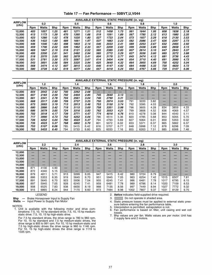
37
Table 17 — Fan Performance — 50BVT,U,V044
LEGEND
NOTES:1. Unit is available with the following motor and drive com-
binations: 7.5, 10, 15 hp standard drive; 7.5, 10, 15 hp medium-static drive; 7.5, 10, 15 hp high-static drive.For 7.5 hp standard drives, the drive range is 780 to 960 rpm.For 10, 15 hp standard and 7.5 hp medium-static drives, thedrive range is 805 to 991 rpm. For 10, 15 hp medium-static and7.5 hp high-static drives the drive range is 960 to 1146 rpm.For 10, 15 hp high-static drives the drive range is 1119 to1335 rpm.
2. Italics indicates field-supplied drive required.3. Do not operate in shaded area.4. Static pressure losses must be applied to external static pres-
sure before entering the fan performance table.5. Interpolation is permitted, extrapolation is not.6. Fan performance is based on filter, unit casing and wet coil
losses.7. Bhp values are per fan. Watts values are per motor. Unit has
2 supply fans and 2 motors.
AIRFLOW (cfm)
AVAILABLE EXTERNAL STATIC PRESSURE (in. wg)0.2 0.4 0.6 0.8 1.0
Rpm Watts Bhp Rpm Watts Bhp Rpm Watts Bhp Rpm Watts Bhp Rpm Watts Bhp12,000 403 1057 1.25 461 1271 1.51 512 1458 1.73 561 1644 1.95 608 1838 2.1812,500 413 1173 1.39 470 1395 1.66 519 1591 1.89 567 1785 2.12 613 1980 2.3513,000 423 1280 1.52 478 1520 1.80 527 1723 2.04 573 1927 2.29 618 2130 2.5313,500 436 1422 1.69 489 1661 1.97 537 1883 2.23 582 2086 2.47 626 2297 2.7314,000 446 1546 1.83 498 1803 2.14 546 2033 2.41 589 2253 2.67 632 2465 2.9214,500 459 1706 2.02 509 1962 2.33 557 2209 2.62 599 2438 2.89 640 2658 3.1515,000 469 1847 2.19 518 2121 2.52 565 2385 2.83 607 2614 3.10 647 2843 3.3716,000 495 2200 2.61 541 2482 2.94 585 2772 3.29 627 3036 3.60 665 3272 3.8817,000 518 2570 3.05 562 2878 3.41 604 3176 3.77 645 3474 4.12 681 3736 4.4317,500 531 2781 3.30 573 3097 3.67 614 3404 4.04 654 3710 4.40 691 3990 4.7318,000 543 3001 3.56 584 3325 3.94 625 3640 4.32 664 3955 4.69 700 4252 5.0419,000 568 3474 4.12 607 3815 4.53 646 4147 4.92 684 4488 5.32 720 4820 5.7219,500 580 3728 4.42 619 4077 4.84 657 4418 5.24 693 4767 5.66 729 5107 6.06
AIRFLOW (cfm)
AVAILABLE EXTERNAL STATIC PRESSURE (in. wg)1.2 1.4 1.6 1.8 2.0
Rpm Watts Bhp Rpm Watts Bhp Rpm Watts Bhp Rpm Watts Bhp Rpm Watts Bhp12,000 654 2042 2.42 700 2262 2.68 — — — — — — — — —12,500 657 2183 2.59 702 2403 2.85 745 2640 3.13 — — — — — —13,000 661 2341 2.78 704 2561 3.04 746 2790 3.31 — — — — — —13,500 668 2517 2.99 709 2737 3.25 750 2974 3.53 791 3220 3.82 — — —14,000 673 2693 3.19 713 2913 3.46 753 3150 3.74 792 3395 4.03 — — —14,500 680 2886 3.42 719 3115 3.69 758 3351 3.98 796 3605 4.28 834 3859 4.3315,000 686 3079 3.65 724 3316 3.93 762 3553 4.21 799 3806 4.52 836 4069 4.5716,000 702 3518 4.17 739 3771 4.47 774 4016 4.76 810 4278 5.08 844 4540 5.1117,000 717 3990 4.73 752 4252 5.04 786 4514 5.36 820 4785 5.68 853 5055 5.7017,500 726 4252 5.04 760 4523 5.37 794 4793 5.69 827 5064 6.01 859 5353 6.0218,000 735 4523 5.37 768 4802 5.70 801 5072 6.02 833 5371 6.37 865 5662 6.3719,000 753 5107 6.06 785 5415 6.42 816 5707 6.77 848 5998 7.12 878 6298 7.0919,500 762 5433 6.45 794 5733 6.80 825 6033 7.16 855 6263 7.51 885 6568 7.48
AIRFLOW (cfm)
AVAILABLE EXTERNAL STATIC PRESSURE (in. wg)2.2 2.4 2.6 2.8 3.0
Rpm Watts Bhp Rpm Watts Bhp Rpm Watts Bhp Rpm Watts Bhp Rpm Watts Bhp12,000 — — — — — — — — — — — — — — —12,500 — — — — — — — — — — — — — — —13,000 — — — — — — — — — — — — — — —13,500 — — — — — — — — — — — — — — —14,000 — — — — — — — — — — — — — — —14,500 871 4130 4.90 — — — — — — — — — — — —15,000 872 4340 5.15 — — — — — — — — — — — —16,000 879 4811 5.71 913 5099 6.05 947 5415 6.42 980 5724 6.79 — — —17,000 886 5353 6.35 919 5645 6.70 951 5945 7.05 983 6254 7.42 1015 6507 7.8117,500 891 5645 6.70 923 5936 7.04 955 6245 7.41 986 6481 7.78 1017 6795 8.1518,000 897 5945 7.05 928 6245 7.41 959 6481 7.78 989 6786 8.14 1020 7109 8.5319,000 908 6525 7.83 938 6830 8.19 968 7135 8.56 997 7449 8.94 1027 7772 9.3219,500 915 6865 8.24 944 7170 8.60 973 7484 8.98 1002 7807 9.37 1031 8129 9.75
Bhp — Brake Horsepower Input to Supply FanWatts — Input Power to Supply Fan Motor
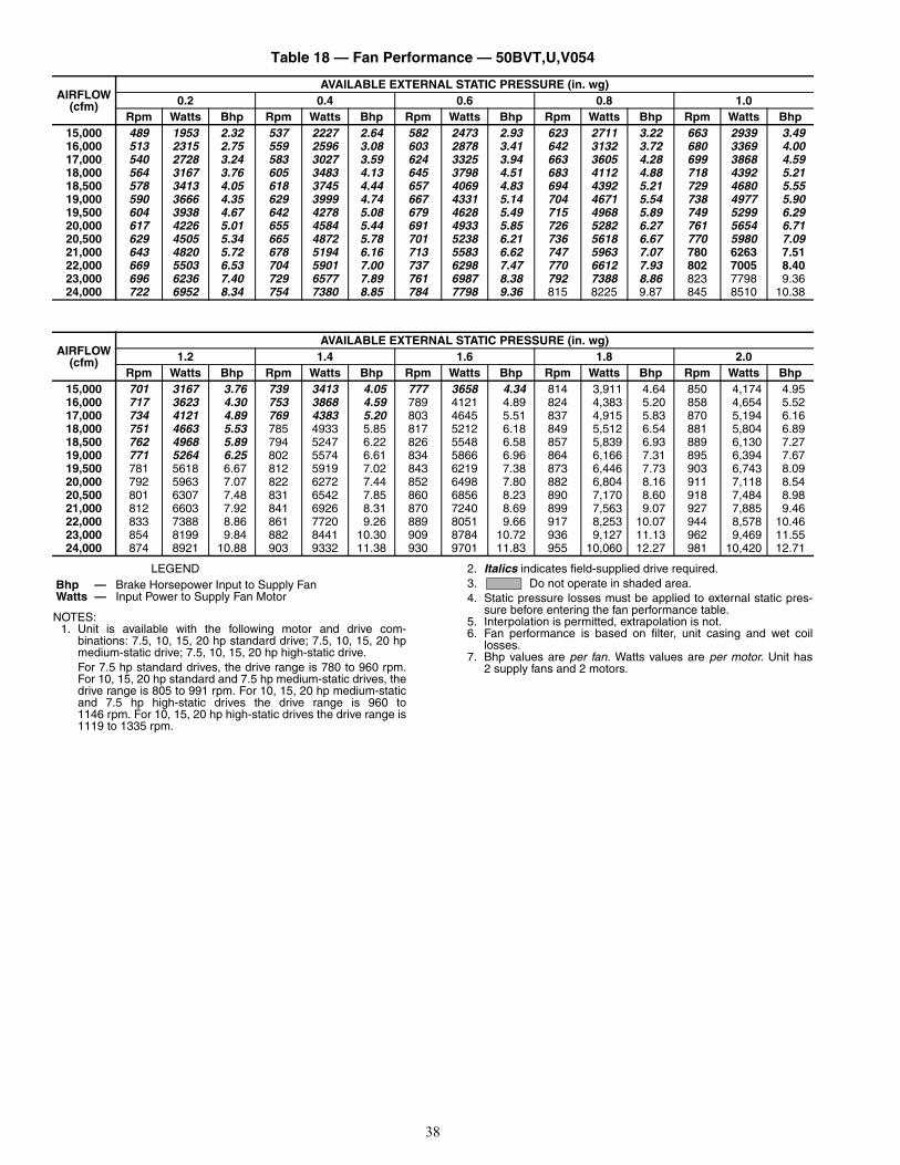
38
Table 18 — Fan Performance — 50BVT,U,V054
LEGEND
NOTES:1. Unit is available with the following motor and drive com-
binations: 7.5, 10, 15, 20 hp standard drive; 7.5, 10, 15, 20 hpmedium-static drive; 7.5, 10, 15, 20 hp high-static drive.For 7.5 hp standard drives, the drive range is 780 to 960 rpm.For 10, 15, 20 hp standard and 7.5 hp medium-static drives, thedrive range is 805 to 991 rpm. For 10, 15, 20 hp medium-staticand 7.5 hp high-static drives the drive range is 960 to1146 rpm. For 10, 15, 20 hp high-static drives the drive range is1119 to 1335 rpm.
2. Italics indicates field-supplied drive required.3. Do not operate in shaded area.4. Static pressure losses must be applied to external static pres-
sure before entering the fan performance table.5. Interpolation is permitted, extrapolation is not.6. Fan performance is based on filter, unit casing and wet coil
losses.7. Bhp values are per fan. Watts values are per motor. Unit has
2 supply fans and 2 motors.
AIRFLOW (cfm)
AVAILABLE EXTERNAL STATIC PRESSURE (in. wg)0.2 0.4 0.6 0.8 1.0
Rpm Watts Bhp Rpm Watts Bhp Rpm Watts Bhp Rpm Watts Bhp Rpm Watts Bhp15,000 489 1953 2.32 537 2227 2.64 582 2473 2.93 623 2711 3.22 663 2939 3.4916,000 513 2315 2.75 559 2596 3.08 603 2878 3.41 642 3132 3.72 680 3369 4.0017,000 540 2728 3.24 583 3027 3.59 624 3325 3.94 663 3605 4.28 699 3868 4.5918,000 564 3167 3.76 605 3483 4.13 645 3798 4.51 683 4112 4.88 718 4392 5.2118,500 578 3413 4.05 618 3745 4.44 657 4069 4.83 694 4392 5.21 729 4680 5.5519,000 590 3666 4.35 629 3999 4.74 667 4331 5.14 704 4671 5.54 738 4977 5.9019,500 604 3938 4.67 642 4278 5.08 679 4628 5.49 715 4968 5.89 749 5299 6.2920,000 617 4226 5.01 655 4584 5.44 691 4933 5.85 726 5282 6.27 761 5654 6.7120,500 629 4505 5.34 665 4872 5.78 701 5238 6.21 736 5618 6.67 770 5980 7.0921,000 643 4820 5.72 678 5194 6.16 713 5583 6.62 747 5963 7.07 780 6263 7.5122,000 669 5503 6.53 704 5901 7.00 737 6298 7.47 770 6612 7.93 802 7005 8.4023,000 696 6236 7.40 729 6577 7.89 761 6987 8.38 792 7388 8.86 823 7798 9.3624,000 722 6952 8.34 754 7380 8.85 784 7798 9.36 815 8225 9.87 845 8510 10.38
AIRFLOW (cfm)
AVAILABLE EXTERNAL STATIC PRESSURE (in. wg)1.2 1.4 1.6 1.8 2.0
Rpm Watts Bhp Rpm Watts Bhp Rpm Watts Bhp Rpm Watts Bhp Rpm Watts Bhp15,000 701 3167 3.76 739 3413 4.05 777 3658 4.34 814 3,911 4.64 850 4,174 4.9516,000 717 3623 4.30 753 3868 4.59 789 4121 4.89 824 4,383 5.20 858 4,654 5.5217,000 734 4121 4.89 769 4383 5.20 803 4645 5.51 837 4,915 5.83 870 5,194 6.1618,000 751 4663 5.53 785 4933 5.85 817 5212 6.18 849 5,512 6.54 881 5,804 6.8918,500 762 4968 5.89 794 5247 6.22 826 5548 6.58 857 5,839 6.93 889 6,130 7.2719,000 771 5264 6.25 802 5574 6.61 834 5866 6.96 864 6,166 7.31 895 6,394 7.6719,500 781 5618 6.67 812 5919 7.02 843 6219 7.38 873 6,446 7.73 903 6,743 8.0920,000 792 5963 7.07 822 6272 7.44 852 6498 7.80 882 6,804 8.16 911 7,118 8.5420,500 801 6307 7.48 831 6542 7.85 860 6856 8.23 890 7,170 8.60 918 7,484 8.9821,000 812 6603 7.92 841 6926 8.31 870 7240 8.69 899 7,563 9.07 927 7,885 9.4622,000 833 7388 8.86 861 7720 9.26 889 8051 9.66 917 8,253 10.07 944 8,578 10.4623,000 854 8199 9.84 882 8441 10.30 909 8784 10.72 936 9,127 11.13 962 9,469 11.5524,000 874 8921 10.88 903 9332 11.38 930 9701 11.83 955 10,060 12.27 981 10,420 12.71
Bhp — Brake Horsepower Input to Supply FanWatts — Input Power to Supply Fan Motor
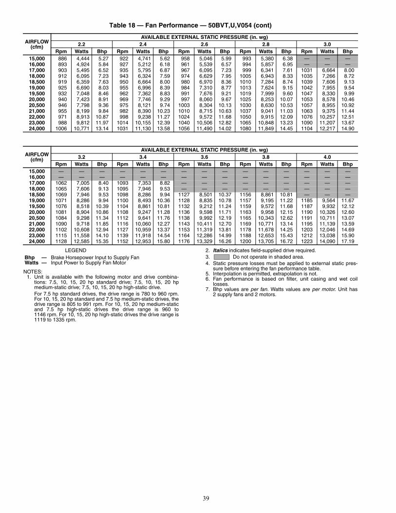
39
Table 18 — Fan Performance — 50BVT,U,V054 (cont)
LEGEND
NOTES:1. Unit is available with the following motor and drive combina-
tions: 7.5, 10, 15, 20 hp standard drive; 7.5, 10, 15, 20 hpmedium-static drive; 7.5, 10, 15, 20 hp high-static drive.For 7.5 hp standard drives, the drive range is 780 to 960 rpm.For 10, 15, 20 hp standard and 7.5 hp medium-static drives, thedrive range is 805 to 991 rpm. For 10, 15, 20 hp medium-staticand 7.5 hp high-static drives the drive range is 960 to1146 rpm. For 10, 15, 20 hp high-static drives the drive range is1119 to 1335 rpm.
2. Italics indicates field-supplied drive required.3. Do not operate in shaded area.4. Static pressure losses must be applied to external static pres-
sure before entering the fan performance table.5. Interpolation is permitted, extrapolation is not.6. Fan performance is based on filter, unit casing and wet coil
losses.7. Bhp values are per fan. Watts values are per motor. Unit has
2 supply fans and 2 motors.
AIRFLOW (cfm)
AVAILABLE EXTERNAL STATIC PRESSURE (in. wg)2.2 2.4 2.6 2.8 3.0
Rpm Watts Bhp Rpm Watts Bhp Rpm Watts Bhp Rpm Watts Bhp Rpm Watts Bhp15,000 886 4,444 5.27 922 4,741 5.62 958 5,046 5.99 993 5,380 6.38 — — —16,000 893 4,924 5.84 927 5,212 6.18 961 5,539 6.57 994 5,857 6.95 — — —17,000 903 5,495 6.52 935 5,795 6.87 967 6,095 7.23 999 6,341 7.61 1031 6,664 8.0018,000 912 6,095 7.23 943 6,324 7.59 974 6,629 7.95 1005 6,943 8.33 1035 7,266 8.7218,500 919 6,359 7.63 950 6,664 8.00 980 6,970 8.36 1010 7,284 8.74 1039 7,606 9.1319,000 925 6,690 8.03 955 6,996 8.39 984 7,310 8.77 1013 7,624 9.15 1042 7,955 9.5419,500 932 7,048 8.46 962 7,362 8.83 991 7,676 9.21 1019 7,999 9.60 1047 8,330 9.9920,000 940 7,423 8.91 969 7,746 9.29 997 8,060 9.67 1025 8,253 10.07 1053 8,578 10.4620,500 946 7,798 9.36 975 8,121 9.74 1003 8,304 10.13 1030 8,630 10.53 1057 8,955 10.9221,000 955 8,199 9.84 982 8,390 10.23 1010 8,715 10.63 1037 9,041 11.03 1063 9,375 11.4422,000 971 8,913 10.87 998 9,238 11.27 1024 9,572 11.68 1050 9,915 12.09 1076 10,257 12.5123,000 988 9,812 11.97 1014 10,155 12.39 1040 10,506 12.82 1065 10,848 13.23 1090 11,207 13.6724,000 1006 10,771 13.14 1031 11,130 13.58 1056 11,490 14.02 1080 11,849 14.45 1104 12,217 14.90
AIRFLOW (cfm)
AVAILABLE EXTERNAL STATIC PRESSURE (in. wg)3.2 3.4 3.6 3.8 4.0
Rpm Watts Bhp Rpm Watts Bhp Rpm Watts Bhp Rpm Watts Bhp Rpm Watts Bhp15,000 — — — — — — — — — — — — — — —16,000 — — — — — — — — — — — — — — —17,000 1062 7,005 8.40 1093 7,353 8.82 — — — — — — — — —18,000 1065 7,606 9.13 1095 7,946 9.53 — — — — — — — — —18,500 1069 7,946 9.53 1098 8,286 9.94 1127 8,501 10.37 1156 8,861 10.81 — — —19,000 1071 8,286 9.94 1100 8,493 10.36 1128 8,835 10.78 1157 9,195 11.22 1185 9,564 11.6719,500 1076 8,518 10.39 1104 8,861 10.81 1132 9,212 11.24 1159 9,572 11.68 1187 9,932 12.1220,000 1081 8,904 10.86 1108 9,247 11.28 1136 9,598 11.71 1163 9,958 12.15 1190 10,326 12.6020,500 1084 9,298 11.34 1112 9,641 11.76 1138 9,992 12.19 1165 10,343 12.62 1191 10,711 13.0721,000 1090 9,718 11.85 1116 10,060 12.27 1143 10,411 12.70 1169 10,771 13.14 1195 11,139 13.5922,000 1102 10,608 12.94 1127 10,959 13.37 1153 11,319 13.81 1178 11,678 14.25 1203 12,046 14.6923,000 1115 11,558 14.10 1139 11,918 14.54 1164 12,286 14.99 1188 12,653 15.43 1212 13,038 15.9024,000 1128 12,585 15.35 1152 12,953 15.80 1176 13,329 16.26 1200 13,705 16.72 1223 14,090 17.19
Bhp — Brake Horsepower Input to Supply FanWatts — Input Power to Supply Fan Motor
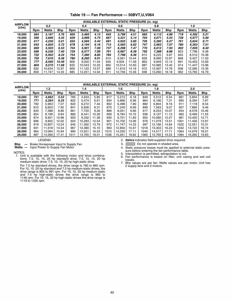
40
Table 19 — Fan Performance — 50BVT,U,V064
LEGEND
NOTES:1. Unit is available with the following motor and drive combina-
tions: 7.5, 10, 15, 20 hp standard drive; 7.5, 10, 15, 20 hpmedium-static drive; 7.5, 10, 15, 20 hp high-static drive.For 7.5 hp standard drives, the drive range is 780 to 960 rpm.For 10, 15, 20 hp standard and 7.5 hp medium-static drives, thedrive range is 805 to 991 rpm. For 10, 15, 20 hp medium-staticand 7.5 hp high-static drives the drive range is 960 to1146 rpm. For 10, 15, 20 hp high-static drives the drive range is1119 to 1335 rpm.
2. Italics indicates field-supplied drive required.3. Do not operate in shaded area.4. Static pressure losses must be applied to external static pres-
sure before entering the fan performance table.5. Interpolation is permitted, extrapolation is not.6. Fan performance is based on filter, unit casing and wet coil
losses.7. Bhp values are per fan. Watts values are per motor. Unit has
2 supply fans and 2 motors.
AIRFLOW (cfm)
AVAILABLE EXTERNAL STATIC PRESSURE (in. wg)0.2 0.4 0.6 0.8 1.0
Rpm Watts Bhp Rpm Watts Bhp Rpm Watts Bhp Rpm Watts Bhp Rpm Watts Bhp18,000 564 3,167 3.76 605 3,483 4.13 645 3,798 4.51 683 4,112 4.88 718 4,392 5.2119,000 590 3,666 4.35 629 3,999 4.74 667 4,331 5.14 704 4,671 5.54 738 4,977 5.9020,000 617 4,226 5.01 655 4,584 5.44 691 4,933 5.85 726 5,282 6.27 761 5,654 6.7121,000 643 4,820 5.72 678 5,194 6.16 713 5,583 6.62 747 5,963 7.07 780 6,263 7.5122,000 669 5,503 6.53 704 5,901 7.00 737 6,298 7.47 770 6,612 7.93 802 7,005 8.4023,000 696 6,236 7.40 729 6,577 7.89 761 6,987 8.38 792 7,388 8.86 823 7,798 9.3624,000 722 6,952 8.34 754 7,380 8.85 784 7,798 9.36 815 8,225 9.87 845 8,510 10.3825,000 750 7,816 9.38 780 8,260 9.91 810 8,561 10.44 839 8,990 10.97 868 9,427 11.5026,000 777 8,595 10.49 806 9,050 11.04 835 9,504 11.59 863 9,949 12.14 891 10,403 12.6927,000 804 9,572 11.68 832 10,043 12.25 860 10,514 12.83 887 10,985 13.40 914 11,447 13.9628,000 832 10,634 12.97 859 11,122 13.57 886 11,610 14.16 912 12,097 14.76 938 12,585 15.3529,000 859 11,747 14.33 885 12,251 14.94 911 12,756 15.56 936 13,260 16.18 962 13,765 16.79
AIRFLOW (cfm)
AVAILABLE EXTERNAL STATIC PRESSURE (in. wg)1.2 1.4 1.6 1.8 2.0
Rpm Watts Bhp Rpm Watts Bhp Rpm Watts Bhp Rpm Watts Bhp Rpm Watts Bhp18,000 751 4,663 5.53 785 4,933 5.85 817 5,212 6.18 849 5,512 6.54 881 5,804 6.8919,000 771 5,264 6.25 802 5,574 6.61 834 5,866 6.96 864 6,166 7.31 895 6,394 7.6720,000 792 5,963 7.07 822 6,272 7.44 852 6,498 7.80 882 6,804 8.16 911 7,118 8.5421,000 812 6,603 7.92 841 6,926 8.31 870 7,240 8.69 899 7,563 9.07 927 7,885 9.4622,000 833 7,388 8.86 861 7,720 9.26 889 8,051 9.66 917 8,253 10.07 944 8,578 10.4623,000 854 8,199 9.84 882 8,441 10.30 909 8,784 10.72 936 9,127 11.13 962 9,469 11.5524,000 874 8,921 10.88 903 9,332 11.38 930 9,701 11.83 955 10,060 12.27 981 10,420 12.7125,000 896 9,855 12.02 924 10,283 12.54 951 10,702 13.06 976 11,079 13.51 1001 11,456 13.9726,000 919 10,857 13.24 945 11,302 13.79 972 11,747 14.33 997 12,166 14.84 1022 12,551 15.3127,000 941 11,918 14.54 967 12,380 15.10 993 12,850 15.67 1018 13,303 16.23 1042 13,722 16.7428,000 964 13,064 15.94 990 13,551 16.53 1015 14,030 17.11 1040 14,517 17.71 1064 14,979 18.2729,000 987 14,269 17.41 1011 14,765 18.01 1036 15,261 18.62 1060 15,765 19.23 1084 16,260 19.83
Bhp — Brake Horsepower Input to Supply FanWatts — Input Power to Supply Fan Motor

41
Table 19 — Fan Performance — 50BVT,U,V064 (cont)
LEGEND
NOTES:1. Unit is available with the following motor and drive combina-
tions: 7.5, 10, 15, 20 hp standard drive; 7.5, 10, 15, 20 hpmedium-static drive; 7.5, 10, 15, 20 hp high-static drive.For 7.5 hp standard drives, the drive range is 780 to 960 rpm.For 10, 15, 20 hp standard and 7.5 hp medium-static drives, thedrive range is 805 to 991 rpm. For 10, 15, 20 hp medium-staticand 7.5 hp high-static drives the drive range is 960 to1146 rpm. For 10, 15, 20 hp high-static drives the drive range is1119 to 1335 rpm.
2. Italics indicates field-supplied drive required.3. Do not operate in shaded area.4. Static pressure losses must be applied to external static pres-
sure before entering the fan performance table.5. Interpolation is permitted, extrapolation is not.6. Fan performance is based on filter, unit casing and wet coil
losses.7. Bhp values are per fan. Watts values are per motor. Unit has
2 supply fans and 2 motors.
AIRFLOW (cfm)
AVAILABLE EXTERNAL STATIC PRESSURE (in. wg)2.2 2.4 2.6 2.8 3.0
Rpm Watts Bhp Rpm Watts Bhp Rpm Watts Bhp Rpm Watts Bhp Rpm Watts Bhp18,000 912 6,095 7.23 943 6,324 7.59 974 6,629 7.95 1005 6,943 8.33 1035 7,266 8.7219,000 925 6,690 8.03 955 6,996 8.39 984 7,310 8.77 1013 7,624 9.15 1042 7,955 9.5420,000 940 7,423 8.91 969 7,746 9.29 997 8,060 9.67 1025 8,253 10.07 1053 8,578 10.4621,000 955 8,199 9.84 982 8,390 10.23 1010 8,715 10.63 1037 9,041 11.03 1063 9,375 11.4422,000 971 8,913 10.87 998 9,238 11.27 1024 9,572 11.68 1050 9,915 12.09 1076 10,257 12.5123,000 988 9,812 11.97 1014 10,155 12.39 1040 10,506 12.82 1065 10,848 13.23 1090 11,207 13.6724,000 1006 10,771 13.14 1031 11,130 13.58 1056 11,490 14.02 1080 11,849 14.45 1104 12,217 14.9025,000 1025 11,824 14.42 1050 12,191 14.87 1074 12,568 15.33 1097 12,944 15.79 1121 13,320 16.2526,000 1045 12,936 15.78 1069 13,320 16.25 1092 13,714 16.73 1115 14,098 17.20 1138 14,492 17.6827,000 1065 14,124 17.23 1088 14,526 17.72 1110 14,927 18.21 1133 15,329 18.70 1155 15,731 19.1928,000 1086 15,397 18.78 1108 15,816 19.29 1131 16,235 19.80 — — — — — —29,000 — — — — — — — — — — — — — — —
AIRFLOW (cfm)
AVAILABLE EXTERNAL STATIC PRESSURE (in. wg)3.2 3.4 3.6 3.8 4.0
Rpm Watts Bhp Rpm Watts Bhp Rpm Watts Bhp Rpm Watts Bhp Rpm Watts Bhp18,000 1065 7,606 9.13 1095 7,946 9.53 — — — — — — — — —19,000 1071 8,286 9.94 1100 8,493 10.36 1128 8,835 10.78 1157 9,195 11.22 1185 9,564 11.6720,000 1081 8,904 10.86 1108 9,247 11.28 1136 9,598 11.71 1163 9,958 12.15 1190 10,326 12.6021,000 1090 9,718 11.85 1116 10,060 12.27 1143 10,411 12.70 1169 10,771 13.14 1195 11,139 13.5922,000 1102 10,608 12.94 1127 10,959 13.37 1153 11,319 13.81 1178 11,678 14.25 1203 12,046 14.6923,000 1115 11,558 14.10 1139 11,918 14.54 1164 12,286 14.99 1188 12,653 15.43 1212 13,038 15.9024,000 1128 12,585 15.35 1152 12,953 15.80 1176 13,329 16.26 1200 13,705 16.72 1223 14,090 17.1925,000 1144 13,697 16.71 1167 14,073 17.17 1190 14,457 17.64 1213 14,850 18.12 1236 15,235 18.5826,000 1160 14,876 18.15 1183 15,269 18.63 1205 15,662 19.11 1227 16,064 19.60 — — —27,000 1177 16,132 19.68 — — — — — — — — — — — —28,000 — — — — — — — — — — — — — — —29,000 — — — — — — — — — — — — — — —
Bhp — Brake Horsepower Input to Supply FanWatts — Input Power to Supply Fan Motor
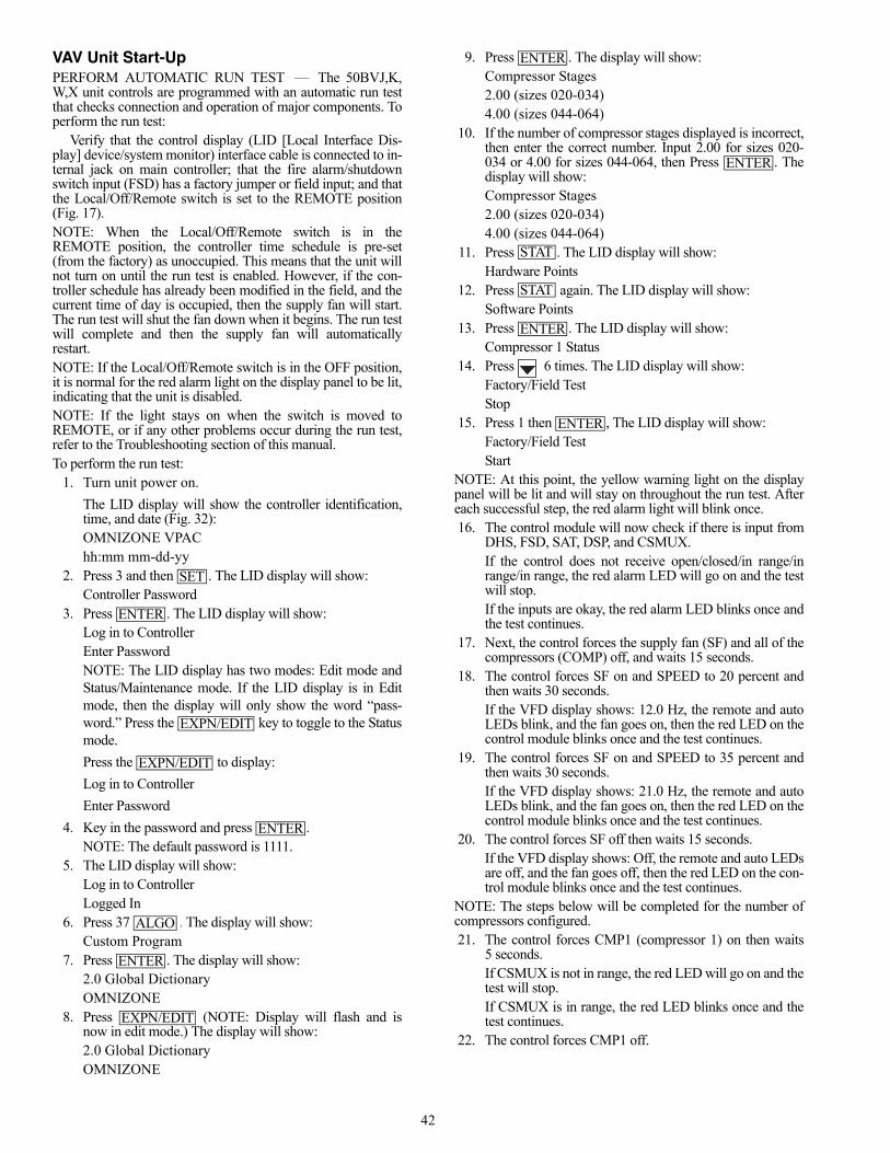
42
VAV Unit Start-UpPERFORM AUTOMATIC RUN TEST — The 50BVJ,K,W,X unit controls are programmed with an automatic run testthat checks connection and operation of major components. Toperform the run test:
Verify that the control display (LID [Local Interface Dis-play] device/system monitor) interface cable is connected to in-ternal jack on main controller; that the fire alarm/shutdownswitch input (FSD) has a factory jumper or field input; and thatthe Local/Off/Remote switch is set to the REMOTE position(Fig. 17).NOTE: When the Local/Off/Remote switch is in theREMOTE position, the controller time schedule is pre-set(from the factory) as unoccupied. This means that the unit willnot turn on until the run test is enabled. However, if the con-troller schedule has already been modified in the field, and thecurrent time of day is occupied, then the supply fan will start.The run test will shut the fan down when it begins. The run testwill complete and then the supply fan will automaticallyrestart.NOTE: If the Local/Off/Remote switch is in the OFF position,it is normal for the red alarm light on the display panel to be lit,indicating that the unit is disabled.NOTE: If the light stays on when the switch is moved toREMOTE, or if any other problems occur during the run test,refer to the Troubleshooting section of this manual.To perform the run test:
1. Turn unit power on.
The LID display will show the controller identification,time, and date (Fig. 32): OMNIZONE VPAChh:mm mm-dd-yy
2. Press 3 and then . The LID display will show:Controller Password
3. Press . The LID display will show:Log in to ControllerEnter PasswordNOTE: The LID display has two modes: Edit mode andStatus/Maintenance mode. If the LID display is in Editmode, then the display will only show the word “pass-word.” Press the key to toggle to the Statusmode.
Press the to display:
Log in to Controller
Enter Password
4. Key in the password and press .NOTE: The default password is 1111.
5. The LID display will show:Log in to ControllerLogged In
6. Press 37 . The display will show:Custom Program
7. Press . The display will show:2.0 Global DictionaryOMNIZONE
8. Press (NOTE: Display will flash and isnow in edit mode.) The display will show:2.0 Global DictionaryOMNIZONE
9. Press . The display will show:Compressor Stages2.00 (sizes 020-034)4.00 (sizes 044-064)
10. If the number of compressor stages displayed is incorrect,then enter the correct number. Input 2.00 for sizes 020-034 or 4.00 for sizes 044-064, then Press . Thedisplay will show:Compressor Stages2.00 (sizes 020-034) 4.00 (sizes 044-064)
11. Press . The LID display will show:Hardware Points
12. Press again. The LID display will show:Software Points
13. Press . The LID display will show:Compressor 1 Status
14. Press 6 times. The LID display will show:Factory/Field TestStop
15. Press 1 then , The LID display will show:Factory/Field TestStart
NOTE: At this point, the yellow warning light on the displaypanel will be lit and will stay on throughout the run test. Aftereach successful step, the red alarm light will blink once.16. The control module will now check if there is input from
DHS, FSD, SAT, DSP, and CSMUX.If the control does not receive open/closed/in range/inrange/in range, the red alarm LED will go on and the testwill stop. If the inputs are okay, the red alarm LED blinks once andthe test continues.
17. Next, the control forces the supply fan (SF) and all of thecompressors (COMP) off, and waits 15 seconds.
18. The control forces SF on and SPEED to 20 percent andthen waits 30 seconds.If the VFD display shows: 12.0 Hz, the remote and autoLEDs blink, and the fan goes on, then the red LED on thecontrol module blinks once and the test continues.
19. The control forces SF on and SPEED to 35 percent andthen waits 30 seconds.If the VFD display shows: 21.0 Hz, the remote and autoLEDs blink, and the fan goes on, then the red LED on thecontrol module blinks once and the test continues.
20. The control forces SF off then waits 15 seconds.If the VFD display shows: Off, the remote and auto LEDsare off, and the fan goes off, then the red LED on the con-trol module blinks once and the test continues.
NOTE: The steps below will be completed for the number ofcompressors configured.21. The control forces CMP1 (compressor 1) on then waits
5 seconds.If CSMUX is not in range, the red LED will go on and thetest will stop.If CSMUX is in range, the red LED blinks once and thetest continues.
22. The control forces CMP1 off.
SET
ENTER
EXPN/EDIT
EXPN/EDIT
ENTER
ALGO
ENTER
EXPN/EDIT
ENTER
ENTER
STAT
STAT
ENTER
ENTER
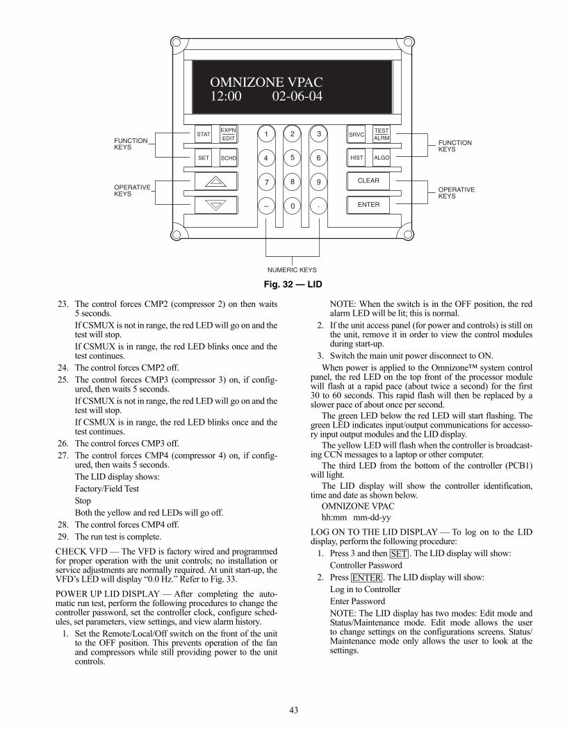
43
23. The control forces CMP2 (compressor 2) on then waits5 seconds.If CSMUX is not in range, the red LED will go on and thetest will stop.If CSMUX is in range, the red LED blinks once and thetest continues.
24. The control forces CMP2 off.25. The control forces CMP3 (compressor 3) on, if config-
ured, then waits 5 seconds.If CSMUX is not in range, the red LED will go on and thetest will stop.If CSMUX is in range, the red LED blinks once and thetest continues.
26. The control forces CMP3 off.27. The control forces CMP4 (compressor 4) on, if config-
ured, then waits 5 seconds.The LID display shows:Factory/Field TestStopBoth the yellow and red LEDs will go off.
28. The control forces CMP4 off.29. The run test is complete.
CHECK VFD — The VFD is factory wired and programmedfor proper operation with the unit controls; no installation orservice adjustments are normally required. At unit start-up, theVFD’s LED will display “0.0 Hz.” Refer to Fig. 33.
POWER UP LID DISPLAY — After completing the auto-matic run test, perform the following procedures to change thecontroller password, set the controller clock, configure sched-ules, set parameters, view settings, and view alarm history.
1. Set the Remote/Local/Off switch on the front of the unitto the OFF position. This prevents operation of the fanand compressors while still providing power to the unitcontrols.
NOTE: When the switch is in the OFF position, the redalarm LED will be lit; this is normal.
2. If the unit access panel (for power and controls) is still onthe unit, remove it in order to view the control modulesduring start-up.
3. Switch the main unit power disconnect to ON.When power is applied to the Omnizone™ system control
panel, the red LED on the top front of the processor modulewill flash at a rapid pace (about twice a second) for the first30 to 60 seconds. This rapid flash will then be replaced by aslower pace of about once per second.
The green LED below the red LED will start flashing. Thegreen LED indicates input/output communications for accesso-ry input output modules and the LID display.
The yellow LED will flash when the controller is broadcast-ing CCN messages to a laptop or other computer.
The third LED from the bottom of the controller (PCB1)will light.
The LID display will show the controller identification,time and date as shown below.
OMNIZONE VPAChh:mm mm-dd-yy
LOG ON TO THE LID DISPLAY — To log on to the LIDdisplay, perform the following procedure:
1. Press 3 and then . The LID display will show:Controller Password
2. Press . The LID display will show:Log in to ControllerEnter PasswordNOTE: The LID display has two modes: Edit mode andStatus/Maintenance mode. Edit mode allows the userto change settings on the configurations screens. Status/Maintenance mode only allows the user to look at thesettings.
Fig. 32 — LID
ENTER
CLEAR
SRVC
HIST ALGO
TESTALRM
3
6
9
1 2
4 5
7 8
0 .–
STAT
SET SCHD
EXPN
EDITFUNCTIONKEYS
OPERATIVEKEYS
FUNCTIONKEYS
OPERATIVEKEYS
NUMERIC KEYS
OMNIZONE VPAC12:00 02-06-04
a50-7425ef
SET
ENTER

44
If the LID display is in Edit mode, then the display willonly show the word “password.” Press the key to toggle to the Status mode. Make sure the LID dis-play shows:
Log in to ControllerEnter Password
3. Key in the password and press .NOTE: The default password is 1111.
4. The LID display will show:Log in to ControllerLogged In NOTE: The user will be automatically logged off after15 minutes of non-use.
CHANGE THE DEFAULT PASSWORD — To change thedefault password, perform the following procedure:NOTE: The password must have already been entered to per-form this procedure.
1. Press 3 and then . The LID display will show:Controller Password
2. Press . The LID display will show:Log in to ControllerLogged in
3. Press . The LID display will show:Password1111 (default password, or previous password entered)
4. Enter the new password (up to 6 digits) and press. The LID display will show:
Password(password just entered)NOTE: Remember this password; write it down.
5. Press twice to leave the password screen and re-turn to the default display screen.
SET THE CLOCK — The user must be logged in to set theclock. To set the clock, perform the following procedure:
1. Press 1 and then . The LID display will show:Set Clock
2. Press . The LID display will show:No MaintenanceNOTE: There is no maintenance information regardingsetting the clock.
3. Press . The LID display will show:Time00:00
4. Enter the time. The time is entered in military time (forexample 14.59 for 2.59 pm). Press then pressthe button. The LID display will show:
Day of Week1
5. Enter the day of week. The numbers 1 through 7 corre-spond to the days of the week (1 = MON, 2 = TUE,3 = WED, 4 = THUR, 5 = FRI, 6 = SAT, 7 = SUN). Press
then press . The LID display will show:
Month1
6. Enter the number of the corresponding month (1 through12). Press then press . The LID displaywill show:
Day1
ECN lamp
Lights whenenergy-savingmode is in operation.
RUN key lamp
Lights when theRUN key isenabled.
RUN key
Pressing this keywhile the RUN keylamp is lightedstarts operations.
RUN lamp
Lights when the inverter isoperating. Blinks when theautomatic acceleration/decelerationis operating
MON lamp
Lights when theinverter is inmonitor mode.
STOP key
Every pressing of this keywhile the RUN key lamp islit will cause a slowdownstop.
VEC lamp
is lit.
Up/down key lamp
Pressing up or downkey when this lampis lit allows thesetting of operationfrequency.
PRG lamp
Lights when the inverter isin parameter setting mode.
Monitor key
Displays operationfrequency, parameters,and error causes.
Built-inpotentiometer lamp
Enter key
Down key
Built-in potentiometer
Operation frequency canbe changed when thebuilt-in potentiometer lamp
Up key
Charge Lamp
Indicates that high voltage isstill present within the inverter.Do not open the terminalboard cover while this is lit.
Lights when sensorlessvector operation controlis running.
RUN STOP
CHARGE
MON ENT
Fig. 33 — 50BV VFD Display
a50-7166ef
EXPN/EDIT
ENTER
SET
ENTER
EXPN/EDIT
ENTER
CLEAR
SET
ENTER
EXPN/EDIT
ENTER
ENTER
ENTER
45
7. Enter the day of the month. Press then press. The LID display will show:
Year09
8. Enter the last two digits of the current year. Press then press . The LID display will show:
Update ClockNo
9. Press 1 and then to update the clock. The LIDdisplay will flash. Press twice to view the de-fault display and the clock should update to the input timeand date.
CONFIGURE SCHEDULES — Schedules are one methodof starting and stopping the unit at specified intervals. To con-figure the schedules, perform the following procedure:
1. Press 1 and then . The LID display will show:Occupancy Algorithm
2. Press . The LID display will show:Time ScheduleEnter to Select
3. Press . If the LID display shows “MODE 0,”then the user is in Maintenance mode and the LID displayis showing the maintenance information for the occupan-cy schedule. Press to enter the configura-tion mode. The LID display will show:
Manual Override Hours0 hoursThis is the first configuration for each occupancyalgorithm and is used to put the schedule in or out ofoccupancy override for the number of hours entered.
4. Press . The LID display will show:Period 1: Day of week00000000The eight digits represent the certain days of the week orholidays this period should apply to: M, Tu, W, Th, F, Sa,Su, and Hol, respectively. Enter a series of 0s or 1s with a1 corresponding to the days that this period should applyto and a 0 for the days that this schedule should not applyto. As an example, entering 11111000 would make theschedule apply to days Monday through Friday and notapply to Saturday, Sunday, or Holidays.
5. Press the button. The LID display will show:Period 1 occupied from00:00
6. Input the occupancy start time for this period. NOTE: 12.00 represents 12:00 pm.
7. Press the to input the occupied to time for period 1. 8. Input the days and times for periods 2 through 8 as
required.9. Press to leave the occupancy programming.
PROGRAM SET POINTS — To program the set points, per-form the following procedure:
1. Press 2 and then . The LID display will show:Setpoint Schedule
2. Press . The LID display will show:Supply Fan StatusSETPT01
3. Press .4. If “No Maintenance” is displayed, press to
view the set point information. The LID display willshow:
Occupied Lo Setpoint0.30 in. H2OThis is the pressure set point below which the fan is con-sidered to be off.
5. Press . The LID display will show:Occupied Hi Setpoint0.40 in. H2OThis is the pressure set point above which the fan is con-sidered to be on.The down or up arrow will also display the unoccupiedlow and high temperature set points. These values shouldbe kept the same as the occupied values.
6. To view set points 02-09, use the following sequence:Press 2 and then . The LID display will show:Setpoint SchedulePress . The LID display will show:Supply Fan StatusSETPT01Press to scroll down to the desired set point. Press
to select.
To view another point, press once to move upone menu level. Then press to scroll down tothe desired set point and press to select.
7. Pressing the button will take the user out of theset point configuration mode.
Set point functions are as follows:Setpoint 02 (VAVRESETbaseline) internally coordinatesthe supply air set point reset in several of the algorithmsand cannot be modified.Setpoint 03 (Heat/Cool Mode & Reset) is used for com-parison by the unit to return air, space temperature, oraverage space temperature through linkage to determinewhen to start reset of the supply air when occupied, whento turn on heat and disable cooling when occupied,and when to bring the unit on for unoccupied heating orcooling.Setpoint 05 (Supply Static Pressure) is used to set the sup-ply air static pressure the unit should maintain. Only theOccupied Low set point may be modified. The othervalues will change to the Occupied Low value shortlyafter it is modified so that all the values remain the same.The set point in the static pressure control algorithm willalso follow and cannot be modified in the algorithm con-figuration screens.Setpoint 06 (Supply Air Temperature) is the supply airtemperature set point. Only the Occupied Low setpoint may be modified. The other values will changeto the Occupied Low value shortly after it is modifiedso that all the values remain the same. The set point inDX VAV staging and some of the other algorithms willalso follow and cannot be modified in the algorithmconfiguration screens.Table 20 lists the available controller set points andtheir default values. Refer to 50BV,XJ Controls, Opera-tion and Troubleshooting manual for additional set pointdescriptions.
ENTER
ENTER
ENTERCLEAR
SCHD
ENTER
ENTER
EXPN/EDIT
CLEAR
SCHD
ENTER
ENTEREXPN/EDIT
SCHD
ENTER
ENTER
CLEAR
ENTER
CLEAR

46
Table 20 — Controller Set Points
CHECK SYSTEM PARAMETERS — To check systemparameters, press the button. The LID display willshow: “Hardware Points”. Press to view the hard-ware points. The user can navigate up and down through thepoints with the and keys.
Press 2 and to display the software points. The usercan navigate up and down through the points with the and
keys.
Refer to Tables 21 and 22 for hardware and software points.
Table 21 — Controller Hardware Points
Table 22 — Software Points
DESCRIPTION DISPLAY SCREENS VALUE UNITS STATUS FORCE NAME
OMNIZONE:SETPT01:Supply Fan Status
Occupied Lo Setpoint 0.3 in. H2O OccLowOccupied Hi Setpoint 0.4 in. H2O OccHgh
Unoccupied Lo Setpoint 0.3 in. H2O UnOccLowUnoccupied Hi Setpoint 0.4 in. H2O UnOccHgh
OMNIZONE:SETPT02:VAVRESETbaseline
Occupied Lo Setpoint 0 dF OccLowOccupied Hi Setpoint 0 dF OccHgh
Unoccupied Lo Setpoint 0 dF UnOccLowUnoccupied Hi Setpoint 0 dF UnOccHgh
OMNIZONE:SETPT03:Heat/Cool Mode & Reset
Occupied Lo Setpoint 70 dF OccLowOccupied Hi Setpoint 74 dF OccHgh
Unoccupied Lo Setpoint 55 dF UnOccLowUnoccupied Hi Setpoint 85 dF UnOccHgh
OMNIZONE:SETPT04:Head Pressure ControlOccupied Lo Setpoint 225 PSIG OccLowOccupied Hi Setpoint 225 PSIG OccHgh
Unoccupied Lo Setpoint 225 PSIG UnOccLowUnoccupied Hi Setpoint 225 PSIG UnOccHgh
OMNIZONE:SETPT05:Supply Static PressureOccupied Lo Setpoint 1.5 in. H2O OccLowOccupied Hi Setpoint 1.5 in. H2O OccHgh
Unoccupied Lo Setpoint 1.5 in. H2O UnOccLowUnoccupied Hi Setpoint 1.5 in. H2O UnOccHgh
OMNIZONE:SETPT06:Supply Air Temperature
Occupied Lo Setpoint 55 dF OccLowOccupied Hi Setpoint 55 dF OccHgh
Unoccupied Lo Setpoint 55 dF UnOccLowUnoccupied Hi Setpoint 55 dF UnOccHgh
OMNIZONE:SETPT07:Building Static Pressure
Occupied Lo Setpoint 0.02 in. H2O OccLowOccupied Hi Setpoint 0.02 in. H2O OccHgh
Unoccupied Lo Setpoint 0.02 in. H2O UnOccLowUnoccupied Hi Setpoint 0.02 in. H2O UnOccHgh
OMNIZONE:SETPT08:BSP raw control
Occupied Lo Setpoint 12.32 ma OccLowOccupied Hi Setpoint 12.32 ma OccHgh
Unoccupied Lo Setpoint 12.32 ma UnOccLowUnoccupied Hi Setpoint 12.32 ma UnOccHgh
OMNIZONE:SETPT09:Humidity Control
Occupied Lo Setpoint 0 %RH OccLowOccupied Hi Setpoint 99 %RH OccHgh
Unoccupied Lo Setpoint 0 %RH UnOccLowUnoccupied Hi Setpoint 99 %RH UnOccHgh
STATENTER
STAT
DESCRIPTION DISPLAY SCREENS VALUE UNITS STATUS FORCE NAME
OMNIZONE:HWP01-32:Hardware points Table 1Supply Air Temperature 67 dF SAT
Duct Static Pressure 0.2 in. H2O DSPComp. Status MUX 1.86 Volts CSMUX
Fire Alarm/ShutDown Enable FSDCond. Water Flow Switch Yes CDWF
Remote Occupancy Disable ROCCDuct High Press. Switch Normal DHS
Entering Water Temp. 69.9 dF EWTCompressor 1 Relay Stop CMP1Compressor 2 Relay Stop CMP2Compressor 3 Relay Stop CMP3Compressor 4 Relay Stop CMP4
Supply Fan/VFD Stop SFVFD Speed Signal 0 % SPEEDNon Critical Fault Off WARN
Critical Fault Off ALARMMixed/Return Air Temp 77.2 dF MA_RA
Dirty Filter Status Clean FLTSPhase Loss Protection Normal PHASE
Ext. Supply Air Reset 0 dF RESETWater Econ. FreezeStat Normal FREEZ
Space_Reset Sensor 79.2 dF SPTVFD Bypass Enable Disable BYPAS
Head Pressure(Comp1) 118.76 PSIG PRESVentilation Request Close VENTR
VAV Terminals Control No TRMCT2-position/Econo Valve 0 % ECONO
Reverse/Head Press Ctrl 100 % Control MVLVHot Water Valve 0 % HWV
Heat Interlock Relay Off HIRBypass Start_Stop Stop BPS_S
VAV Terminals Open MAX Close TRMOPOMNIZONE:HWP33-64:
Hardware points Table 2Cooling Tower Sump
Temp. 57.5 dF TWR
Building Static Milliamp 12.51 ma BSPCondenser Leaving Water 70.3 dF LWT
Indoor Air Quality 587.21 IAQIndoor Relative Humidity 49.7 % IRH
Outdoor Air Temp. 76.1 dF OATHeat Stage 1 Off HEAT1Heat Stage 2 Off HEAT2Heat Stage 3 Off HEAT3Heat Stage 4 Off HEAT4
Pump Request Off PUMPCooling Tower Request Off TOWER
Exhaust Fan 0 % EXHExt. Dehumidification Stop DEHUM
DESCRIPTION DISPLAY SCREENS VALUE UNITS STATUS FORCE NAME
OMNIZONE:SWP65-96:Software Points
Compressor 1 Status Off CLO1Compressor 2 Status Off CLO2Compressor 3 Status Off CLO3Compressor 4 Status Off CLO4
Bypass Acc Panel Secure No BP_SAFEDX VAVRESET control 0 dF VAVRESET
Factory/Field Test Stop FLDTSTBuilding Static Pressure 0.03 in. H2O BSP_IN
Time Clock Off TIMCLOCKCooling Disable COOLOK
Supply Fan Status Off Control SFSOk to run Fan No OKFAN
OK Fan + Sup. Fan Stat FALSE SF_SFSFan + Cond. Water Flow FALSE FAN_CDWF
Equipment Mode Cool Control MODEActivate Evacuation
Mode Disable EVAC
Space Control Point 74 dF CTRLPTMod. Econ Enabled No Control ECON_OK
Head Pressure Control Disable Control HEADEconomizer Control
Temp. 77.22 dF ECONPT
Compressor Cooling Disable COMPRESDuct Static Failure Normal DSP_ALM
Compressor 1 Alarm Normal C1_ALMCompressor 2 Alarm Normal C2_ALMCompressor 3 Alarm Normal C3_ALMCompressor 4 Alarm Normal C4_ALM
Cond. Flow Alarm Status Disable Control CDWF_ST
47
DISPLAY ALARM HISTORY — If the controller is indicat-ing there are alarms, the user can view the alarm history bypressing the button. The LID display will show “AlarmHistory.” Press . The LID display will show the dateand type of alarm.
As an example, if the LID display shows:ALARM — 10:55 02-11-04SFSThat display indicates that on 02-11-04 at 10:55 a.m. the
supply fan was either on when it had not been commanded onor was off when it was commanded on.
The user can view other stored alarms by pressing the up anddown arrows. The twenty-four most recent alarms are stored.
CONFIGURE CUSTOM PROGRAMMING SELEC-TIONS — To configure the custom programming selections,perform the following procedure:
1. Press 37 . The LID display will show:Custom Program
2. Press . The LID display will show:2.0 Global DictionaryOMNIZONE
3. Press . The display indicates “No Data.” Press then press . Press again.
The LID display should now show:
Compressor Stages2.00 (sizes 020-034)4.00 (sizes 044-064)
4. Press 7 times. The display will show:0 = RAT, 1 = MAT 2 = NONE0.00
5. Press 2 then . The display will show:0 = RAT, 1 = MAT 2 = NONE2.00
6. If RAS is installed at EWT input, press 3 times.The display will show:EWT Reset 0 = NO, 1 = YES0.00
7. Press 1 then . The display will now show:EWT Reset 0 - NO, 1 = YES1.00
8. Use the down and up arrows to select the other configura-tion parameters as required. See Table 23 for a list of con-figuration parameters.
Table 23 — Configuration Parameters
*Not used.
SET CONTROLLER ADDRESS — To set the address of theOmnizone™ system control panel controller, perform the fol-lowing procedure:
1. Press 7 and then . Press and then.
2. Type in the CCN element number and press .3. Press the button. Type in the CCN bus number and
press .
LOG OFF FROM CONTROLLER — To log off from theOMNIZONE system control panel controller Press 3 and then
. The controller password will be displayed.
1. Press . The display should show:
Log in to ControllerLogged inIf this is not displayed, Press until it is dis-played.
2. Press the button. The LID display will show:Log out of Controller Press 1. Press to log off.
Sequence of Operation (CV Only) — The follow-ing sequence applies to constant volume units only.
Cooling is initiated when the set point in the remote thermo-stat is not met (space temperature is higher than set point). Theunit sequence of operation is as follows:
The 50BV units can be remotely authorized to be controlledby the thermostat through the optional energy managementsystem relay (EMS). The coil is powered by the energy man-agement (building automation) system whose contacts are inseries with the ‘R’ 24-v ac terminal with potential across ‘C’(transformer common). With this terminal open, power will beinterrupted to the thermostat. Closure of this contact will allowthe 50BV unit to operate from the thermostat.
Contact closure at the ‘G’ terminal will provide power tothe supply fan contactor, energizing the supply fan. The supplyfan will be off during unoccupied schedule, depending uponthe features of the thermostat used. The ‘O’ terminal energizesthe reversing valve (heat pump units only). Typically ‘Y1’ willalso be energized at this time for cooling operation. During thesecond stage of cooling, ‘Y2’ will be initialized after a mini-mum run time and after there is a differential from set pointplus a deadband or a proportional plus integral calculation,which is based upon demand and the length of time space-temperature is greater than set point. Additional assurance isprovided by a delay on make timer in the second stage com-pressor contactor circuit to avoid dual compressor in-rush start-ing current.
For 4 compressor units, a call for the first stage of coolingwill turn on compressors 1 and 2. The second stage of coolingwill turn on compressors 3 and 4.
Heating mode (heat pump models only) follows the samesequence as above except that the reversing valve is notenergized.WATER ECONOMIZER COOLING — The unit divertscondenser inlet waterflow through an optional economizer coilto precool evaporator entering airflow. If the entering watertemperature is colder than the setting on the aquastat, and thereturn-air temperature is warmer than the setting on the return-air thermostat, the 3-way diverting valve will direct water tothe economizer coil.
Economizer water flow is in series with the condensersallowing compressor operation while the economizer isoperating.
DESCRIPTION VALUE UNITS NAMECompressor Stages 2.00 NUM_CMPReset Ratio 3.00 dF RSET_RTOCDWF 0=NO,1=YES 0.00 CDFW_SWT*ECON 0=NO,1=YES 0.00 EWT_SNSEWT Reset 0=NO,1=YES 0.00 EWT_RST*MOD.VLV 0=NO,1=YES 0.00 MOD_ECON*0=CONST.,1=VARIABLE 0.00 FLOW_TYP0=RAT,1=MAT 2=NONE 2.00 MARA_SNSPHASE 0=NO,1=YES 0.00 PHAS_SWT*FREEZ 0=NO,1=YES 0.00 FREZ_SWT*ENABLE ECON. 68.00 dF ECON_SETSPT 0=NO,1=YES 0.00 SPT_SNSPRES 0=NO,1=YES 0.00 PRES_SNSTWR 0=NO,1=YES 0.00 TWR_SNSLWT 0=NO,1=YES 0.00 LWT_SNSIAQ 0=NO,1=YES 0.00 IAQ_SNSIRH 0=NO,1=YES 0.00 IRH_SNSBSP 0=NO,1=YES 0.00 BSP_SNSBSP Range 1.00 in. H2O BSP_RNGBSP LOW VALUE –0.50 in. H2O BSP_LOW
HISTENTER
ALGO
ENTER
ENTERCLEAR EXPN/EDIT ENTER
ENTER
ENTER
SRVC ENTEREXPN/EDIT
ENTER
ENTER
SET
ENTER
EXPN/EDIT
ENTER
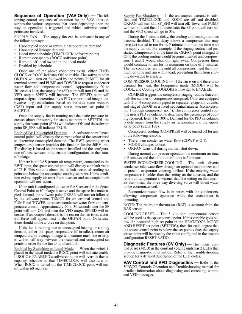
48
Sequence of Operation (VAV Only) — The fol-lowing control sequence of operation for the VAV units de-scribes the various sequences that occur depending upon theway an operation is triggered and which software controlpoints are involved.SUPPLY FAN — The supply fan can be activated in any ofthe following ways:• Unoccupied space or return air temperature demand• Unoccupied linkage demand• Local time schedule (TIMCLOCK software point)• Remote occupancy (ROCC software point)• Remote-off-local switch in the local mode• Enabled by schedule
Once one of the above conditions exists, either TIME-CLOCK or ROCC indicates ON or enable. The software pointOKFAN will turn on followed by the points TRMCT for airterminal control and PUMP and TOWER to request condenserwater flow and temperature control. Approximately 20 to30 seconds later, the supply fan (SF) point will turn ON and theVFD output SPEED will increase. The SPEED point willoutput a signal, determined by a PID (proportional integral de-rivative loop) calculation, based on the duct static pressure(DSP) input and the supply static pressure set point inSETPT05.
Once the supply fan is running and the static pressure in-creases above the supply fan status set point in SETPT01, thesupply fan status point (SFS) will indicate ON and the softwarepoint SF_SFS will indicate TRUE. Enabled By Unoccupied Demand — A software point “spacecontrol point” will display the current value of the sensor usedto determine unoccupied demand. The EWT (entering watertemperature) sensor provides this function for the 50BV unit.The display is based on the sensors installed and the configura-tion of these sensors in the custom configuration, or the statusof linkage.
If there is no RAS (return air temperature) connected to theEWT input, the space control point will display a default valueof 75 F. This value is above the default occupied cooling setpoint and below the unoccupied cooling set point. If this condi-tion exists, supply air reset from a sensor and unoccupied unitoperation will not occur.
If the unit is configured to use an RAS sensor for the SpaceControl Point or if linkage is active and the space has unoccu-pied demand, the software point OKFAN will turn on followedby the software points TRMCT for air terminal control andPUMP and TOWER to request condenser water flow and tem-perature control. Approximately 20 to 30 seconds later the SFpoint will turn ON and then the VFD output SPEED will in-crease. If unoccupied demand is the reason the fan is on, a con-trol force will appear next to the OKFAN point. Otherwise,there should not be a force on that point.
If the fan is running due to unoccupied heating or coolingdemand, either the space temperature (if installed), return-airtemperature, or average linkage temperature must rise or dropto within half way between the occupied and unoccupied setpoints in order for the fan to turn back off.Enabled by Switching to Local Mode — When the switch isplaced in the Local mode the ROCC point will indicate enable.If ROCC is ENABLED a software routine will override the oc-cupancy schedule so that TIMECLOCK will also turn on.When ROCC is turned off the TIMECLOCK point will turnoff within 60 seconds.
Supply Fan Shutdown — If the unoccupied demand is satis-fied and TIMECLOCK and ROCC are off and disabled,OKFAN will turn off, SF_SFS will turn off, Tower and PUMPwill turn off, and then 5 minutes later the SF point will turn offand the VFD speed will go to 0%.
During the 5-minute delay, the cooling and heating routinesbecome disabled. This delay allows a compressor that mayhave just started to run for its 5-minute minimum on time withthe supply fan on. For example, if the staging routine had juststarted Compressor 3 at the time the OKFAN point changed toOFF, the cooling routine would become disabled and compres-sors 1 and 2 would shut off right away. Compressor threewould continue to run for its minimum on time of 5 minutes.The fan continues running until all compressors meet the mini-mum on time and run with a load, preventing them from shut-ting down due to a safety.COMPRESSOR COOLING — If the fan is on and there is nodemand for heat, the Equipment mode (MODE) will beCOOL, and Cooling (COOLOK) will switch to ENABLE.
COMRES triggers the compressor staging routine that con-trols the number of compressors energized. Units are equippedwith 2 or 4 compressors piped in separate refrigerant circuits,and staged On/Off in a fixed sequential manner (compressorno. 1 through compressor no. 4). The compressor control rou-tine uses a PID calculation to determine the percentage of cool-ing required, from 1 to 100%. Demand for the PID calculationis determined from the supply air temperature and the supplyair setpoint (SETPT06).
Compressor cooling (COMPRES) will be turned off for anyof the following reasons:• There is no condenser water flow (CDWF is Off). • MODE changes to heat.• OKFAN turns off during normal shut down.
During normal compressor operation the minimum on timeis 5 minutes and the minimum off time is 5 minutes.WATER ECONOMIZER COOLING — The unit divertscondenser inlet waterflow through an optional economizer coilto precool evaporator entering airflow. If the entering watertemperature is colder than the setting on the aquastat, and thereturn-air temperature is warmer than the setting on the return-air thermostat, the three-way diverting valve will direct waterto the economizer coil.
Economizer water flow is in series with the condensers,allowing compressor operation while the economizer isoperating.NOTE: The return-air thermostat (RAT) is separate from theRAS sensor.COOLING RESET — The 5 kilo-ohm temperature sensorwill be used as the space control point. If this variable goes be-low the occupied high set point in the HEAT/COOL MODEAND RESET set point (SETPT03), then for each degree thatthe space control point is below the set point value, the supplyair set point will be reset by the value configured in the customconfiguration RESET RATIO.
Diagnostic Features (CV Only) — The main con-trol board (MCB) in the constant volume units has 2 LEDs thatprovide diagnostic information. Refer to the Troubleshootingsection for a detailed description of the LED codes.
VAV Control and VFD Diagnostics — Refer to the50BV,XJ Controls Operation and Troubleshooting manual fordetailed information about diagnosing and correcting controland VFD messages.
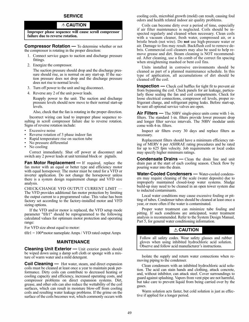
49
SERVICE
Compressor Rotation — To determine whether or notthe compressor is rotating in the proper direction:
1. Connect service gages to suction and discharge pressurefittings.
2. Energize the compressor.The suction pressure should drop and the discharge pres-sure should rise, as is normal on any start-up. If the suc-tion pressure does not drop and the discharge pressuredoes not rise to normal levels:
3. Turn off power to the unit and tag disconnect.4. Reverse any 2 of the unit power leads.
Reapply power to the unit. The suction and dischargepressure levels should now move to their normal start-uplevels.Also, check that the fan is rotating in the proper direction.
Incorrect wiring can lead to improper phase sequence re-sulting in scroll compressor failure due to reverse rotation.Signs of reverse rotation include:• Excessive noise• Reverse rotation of 3 phase indoor fan• Rapid temperature rise on suction tube• No pressure differential• No cooling
Correct immediately. Shut off power at disconnect andswitch any 2 power leads at unit terminal block or pigtails.
Fan Motor Replacement — If required, replace thefan motor with an equal or better type and efficiency motorwith equal horsepower. The motor must be rated for a VFD orinverter application. Do not change the horsepower unlessthere is a system design requirement change and VFD sizeanalysis.CHECK/CHANGE VFD OUTPUT CURRENT LIMIT —The VFD provides additional fan motor protection by limitingthe output current to a programmed value. This value has beenfactory set according to the factory-installed motor and VFDsizing options.
If the VFD and/or motor is replaced, the VFD setup modeparameter "tHr1" should be reprogrammed to the followingcalculated values for optimum motor protection and operatingrange:For VFD size about equal to motor: tHr1 = 100*motor nameplate Amps / VFD rated output Amps
MAINTENANCE
Cleaning Unit Exterior — Unit exterior panels shouldbe wiped down using a damp soft cloth or sponge with a mix-ture of warm water and a mild detergent.
Coil Cleaning — Hot water, steam, and direct expansioncoils must be cleaned at least once a year to maintain peak per-formance. Dirty coils can contribute to decreased heating orcooling capacity and efficiency, increased operating costs, andcompressor problems on direct expansion systems. Dirt,grease, and other oils can also reduce the wettability of the coilsurfaces, which can result in moisture blow-off from coolingcoils and resulting water leakage problems. If the grime on thesurface of the coils becomes wet, which commonly occurs with
cooling coils, microbial growth (mold) can result, causing foulodors and health related indoor air quality problems.
Coils can become dirty over a period of time, especiallyif air filter maintenance is neglected. Coils should be in-spected regularly and cleaned when necessary. Clean coilswith a vacuum cleaner, fresh water, compressed air, or abristle brush (not wire). Do not use high-pressure water orair. Damage to fins may result. Backflush coil to remove de-bris. Commercial coil cleaners may also be used to help re-move grease and dirt. Steam cleaning is NOT recommend-ed. After cleaning, use a fin comb of the correct fin spacingwhen straightening mashed or bent coil fins.
Units installed in corrosive environments should becleaned as part of a planned maintenance schedule. In thistype of application, all accumulations of dirt should becleaned off the coil.
Inspection — Check coil baffles for tight fit to prevent airfrom bypassing the coil. Check panels for air leakage, particu-larly those sealing the fan and coil compartments. Check forloose electrical connections, compressor oil levels, proper re-frigerant charge, and refrigerant piping leaks. Before start-up,be sure all optional service valves are open.
Air Filters — The 50BV single-piece units come with 1-in.filters. The standard 1-in. filters provide lower pressure dropand longer filter service intervals. The 50BV modular unitscome with 4-in. filters.
Inspect air filters every 30 days and replace filters asnecessary.
Replacement filters should have a minimum efficiency rat-ing of MERV 6 per ASHRAE rating procedures and be ratedfor up to 625 fpm velocity. Job requirements or local codesmay specify higher minimum ratings.
Condensate Drains — Clean the drain line and unitdrain pan at the start of each cooling season. Check flow bypouring water into the drain.
Water-Cooled Condensers — Water-cooled condens-ers may require cleaning of the scale (water deposits) due toimproperly maintained closed-loop water systems. Sludgebuild-up may need to be cleaned in an open tower system dueto inducted contaminants.
Local water conditions may cause excessive fouling or pit-ting of tubes. Condenser tubes should be cleaned at least once ayear, or more often if the water is contaminated.
Proper water treatment can minimize tube fouling andpitting. If such conditions are anticipated, water treatmentanalysis is recommended. Refer to the System Design Manual,Part 5, for general water conditioning information.
Isolate the supply and return water connections when re-moving piping to the condenser.
Clean condensers with an inhibited hydrochloric acid solu-tion. The acid can stain hands and clothing, attack concrete,and, without inhibitor, can attack steel. Cover surroundings toguard against splashing. Vapors from vent pipe are not harmful,but take care to prevent liquid from being carried over by thegases.
Warm solution acts faster, but cold solution is just as effec-tive if applied for a longer period.
CAUTIONImproper phase sequence will cause scroll compressorfailure due to reverse rotation.
CAUTION
Follow all safety codes. Wear safety glasses and rubbergloves when using inhibited hydrochloric acid solution.Observe and follow acid manufacturer’s instructions.

50
GRAVITY FLOW METHOD (Fig. 34) — Do not add solu-tion faster than the vent can exhaust the generated gases.
When condenser is full, allow the solution to remain over-night then drain the condenser and flush with clean water. Fol-low acid manufacturer’s instructions.FORCED CIRCULATION METHOD (Fig. 35) — Fully openthe vent pipe when filling the condenser. The vent may beclosed when the condenser is full and the pump is operating.
Regulate the flow to the condenser with a supply line valve.If the pump is the non-overloading type, the valve may be fullyclosed while the pump is running.
For average scale deposit, allow the solution to remain inthe condenser overnight. For heavy scale deposit, allow a full24 hours. Drain the condenser and flush with clean water.Follow acid manufacturer’s instructions.
Fan Motor Lubrication — The fan motor was properlylubricated at the time of manufacture. Lubricate the fanmotor(s) with SAE-20 (Society of Automotive Engineers) non-detergent electric oil.
Fan Bearing Lubrication — Inspect the fan bearingsfor proper lubrication every 6 month or 2500 hours of opera-tion, whichever comes first. Standard units have grease fittingson the fan shaft bearings, located on each side of the blowerwheel. Lubricate bearings with a lithium-based grease (NLGIGrade 2).
Fan Sheaves — Factory-supplied drives are pre-alignedand tensioned, however, it is recommended that the belt tensionand alignment be checked before starting the unit. Alwayscheck the drive alignment after adjusting belt tension. To install sheaves on the fan or motor shaft:
1. Isolate power to the unit.2. Remove side unit access panel(s).3. Remove any rust-preventive coating on the fan shaft.4. Make sure the shaft is clean and free of burrs. Add grease
or lubricant to bore of sheave before installing. 5. Mount sheave on the shaft; to prevent bearing damage, do
not use excessive force. Each factory-assembled fan, shaft, and drive sheave assem-
bly is precision aligned and balanced. If excessive unitvibration occurs after field replacement of sheaves, the unitshould be rebalanced. To change the drive ratio, follow thesteps in the Evaporator Fan Performance Adjustment section(page 51).
After 1 to 3 minutes of operation, check the belt tension.Also check tension frequently during the first 24 hours of oper-ation and adjust if necessary. Periodically check belt tensionthroughout the run-in period, which is normally the initial72 hours of operation.ALIGNMENT — Make sure that fan shafts and motor shaftsare parallel and level. The most common causes of misalign-ment are nonparallel shafts and improperly located sheaves.Where shafts are not parallel, belts on one side are drawn tight-er and pull more than their share of the load. As a result, thesebelts wear out faster, requiring the entire set to be replaced be-fore it has given maximum service. If misalignment is in thesheave, belts enter and leave the grooves at an angle, causingexcessive belt and sheave wear.Shaft Alignment — Check shaft alignment by measuring thedistance between the shafts at 3 or more locations. If the dis-tances are equal, then the shafts are parallel.Sheave Alignment
1. To check the location of the fixed sheaves on the shafts,use a straightedge or a piece of string. If the sheaves areproperly aligned, the string will touch them at the pointsindicated by the arrows in Fig. 36. Rotate each sheave ahalf revolution to determine whether the sheave is wob-bly or the drive shaft is bent. Correct any misalignment.
2. With sheaves aligned, tighten cap screws evenly andprogressively.NOTE: There should be a 1/8-in. to 1/4-in. gap betweenthe mating part hub and the bushing flange. If the gap isclosed, the bushing is probably the wrong size.
3. With taper-lock bushed hubs, be sure the bushing boltsare tightened evenly to prevent side-to-side pulley wob-ble. Check by rotating sheaves and rechecking sheavealignment. When substituting field-supplied sheaves forfactory-supplied sheaves, only the motor sheave shouldbe changed.
Fig. 34 — Gravity Flow Method
Fig. 35 — Forced Circulation Method
a50-186tf
a50-187tf
IMPORTANT: PILLOW BLOCK STYLE FAN BEAR-INGS: Bearings have been prelubricated with high qualitygrease. Bearings must be relubricated once every 6 monthsor every 2500 hours of operation whichever comes first.

51
Evaporator Fan Performance Adjustment —To change fan speeds from factory settings:
1. Shut off unit power supply.2. Loosen nuts on the 4 carriage bolts in the mounting
base. Using adjusting bolts and plate, slide the motorand remove the belt.
3. Loosen movable-pulley flange setscrew. 4. Screw the movable flange toward the fixed flange to
increase speed, and away from the fixed flange todecrease speed. Increasing the fan speed increases theload on the motor. Do not exceed the maximum speedspecified in Tables 2A and 2B.
5. Set the movable flange at nearest keyway of the pulleyhub and tighten the setscrew. (See Tables 2A and 2Bfor speed change for each full turn of pulley flange.)
6. Replace and tighten the belts (see Belt Tension Adjust-ment section).
7. Restore power to the unit. To align fan and motor pulleys:
1. Loosen fan pulley setscrews.2. Slide fan pulley along fan shaft.3. Make angular alignment by loosening motor from
mounting plate.4. Restore power to unit.
BELT TENSION ADJUSTMENT — Using a gage, apply4 lb of force to the center of the belt and adjust the tension untila deflection of 1/64-in. is achieved for every inch of shaft centerdistance. See Fig. 37.
Ideal belt tension is the lowest value under which belt slipwill not occur at peak load conditions.
Charging the SystemREMOTE AIR-COOLED UNITS — The 50BVE,K,U,X unitsare shipped with a holding charge of dry nitrogen. Remotecondensers, interconnecting piping, and refrigerant to charge thesystem are all field supplied.
To evacuate the system, refer to GTAC II, Module 4, Dehy-dration for Proper Evacuation and Dehydration Techniques.To charge the 50BVE,K,U,X systems:
1. Add an initial minimum refrigerant charge after evacu-ation to allow the unit to start. Refer to Tables 24A and24B. Additional refrigerant will be added based on thelength of interconnecting piping and vertical separa-tion between the indoor unit and the condenser(s).
Table 24A — Minimum Operating Charge (lb),50BVE,K Units Matched with 09DK Condensers
Table 24B — Minimum Operating Charge (lb),50BVU,X Units Matched with 09DK Condensers
2. To finish charging the system, make sure the unitis running at full-load operating conditions. Charge toa clear sight glass. Refer to GTAC II, Module 5,Charging, Recovery, Recycling and Reclamation andthe Refrigerant Service Techniques manual for propercharging techniques.
3. Add 10 lb of R-22 or R-410A over a clear sight glassto flood subcooler section of the condenser coils.
4. Alternately, and as a double-check, when properlycharged at full-load operating conditions, there shouldbe 15 F subcooling entering the TXV (the differencebetween saturated condenser temperature and actualliquid temperature entering the TXV).
Compressor Oil — All units are factory charged withoil. It is not necessary to add oil unless compressor(s) is re-moved from the unit. If necessary, oil can be removed/chargedvia Schrader fitting. Operate the system at high evaporator tem-perature prior to oil recharge to assist oil return to the compres-sor(s) from other system components. If necessary, rechargethe system as shown in Table 25.
Table 25 — Oil Recharge
TROUBLESHOOTINGRefer to Tables 26-28 to determine the possible cause of theproblem and the associated procedure necessary to correct it.See Fig. 38-47 for unit and control wiring.
Fig. 36 — Sheave Alignment
a50-7135tf
BELT SPAN
LB FORCE
DEFLECTION
Fig. 37 — Fan Belt Tension
a50-7136ef
UNIT SIZE 020 024 028 034Circuit 1...2 8.1...8.1 9.1...9.1 9.1...9.1 18...18
UNIT SIZE 034 044 054 064Circuit 1...2 18...18 10...10 18...18 18...18Circuit 3...4 - 10...10 18...18 18...18
50BVUNIT SIZE COMPRESSOR
OILRECHARGE
(oz)
OILTYPE
PARTNUMBER
C,E,Q,J,K
020 ZR94KC 81
3GS 150viscosityyellowmineral
oil
P903-0101
024 ZR108KC 106028 ZR144KC 106034 ZR19M3 137
T,U,V,W,X
034 ZR19M3 137044 ZR125KC 106054 ZR16M3 137064 ZR19M3 137

52
Table 26 — Run Test Troubleshooting (VAV Units Only)
NOTE: For more information on VAV controls, refer to the 50BV,XJ Controls Operation and Troubleshooting Manual.
PROBLEM POSSIBLE CAUSEControl modules do not have lights when unit power is on. Transformer open. Circuit breaker open. Power wiring open. Module failure.Control display does not light up when unit power is on. Connection location. Interface cable open. Display failure.Run test will not start. Pre-existing ALARM (red)? Not “Logged in” with password.
Switch not in local.WARN (yellow) LED does not light during run test. Wiring open. Lamp failure. Control module failure.ALARM (red) LED does not light during run test. Wiring open. Lamp open. Control module failure.Run test stops, ALARM (red) LED light is lit after it blinks once. Bypass switch to LINE. Mode switch to OFF. Duct high
pressure switch open. Fire shutdown input or jumper open.Supply air temperature out of range. Duct static pressure sensor out of range. Compressor resistor board wiring error or failure.
Fan does not start/ALARM (red) LED blinks 2 times. Fan relay failure.Run test stop, ALARM (red) LED is lit after blinking 3 times. Wiring open. VFD connection error. VFD setup error. Fan relay failure.
Current isolator failure. Control module failure.Run test stop, ALARM (red) LED is lit after it blinks 4 times.Fan does not increase speed.
VFD connection error. VFD setup error. Current isolator load adjustment too low.
Fan does not stop after ALARM (red) LED blinks 5 times. Fan relay failure.Fan rotation is backwards. VFD to motor wiring sequence error. VFD setup error.Run test stop, ALARM (red) LED is lit after blinking 6 times.Compressor 1 does not start.
Wiring open. Compressor resistor board wiring error or failure. High pressure switch, low pressure switch, coil frost switch, or compressor protection module open. Compressor relay failure. Contactor failure. Control module failure. No refrigerant charge.
Run test stop, ALARM (red) LED is lit after blinking 7 times.Compressor 2 does not start.
Wiring open. Compressor resistor board wiring error or failure. High pressure switch, low pressure switch, coil frost switch, or compressor protection module open. Compressor relay failure. Contactor failure. Control module failure. No refrigerant charge.
Run test stop, ALARM (red) LED is lit after blinking 8 times.Compressor 3 does not start.
Wiring open. Compressor resistor board wiring error or failure. High pressure switch, low pressure switch, coil frost switch, or compressor protection module open. Compressor relay failure. Contactor failure. Control module failure. No refrigerant charge.
Run test stop, ALARM (red) LED is lit after blinking 9 times.Compressor 4 does not start.
Wiring open. Compressor resistor board wiring error or failure. High pressure switch, low pressure switch, coil frost switch, or compressor protection module open. Compressor relay failure. Contactor failure. Control module failure. No refrigerant charge.
Compressor rotation is backwards. Field power wiring sequence error. Compressor power wiring sequence error.“C” message in I/O status display. No input signal or communication failure.“Service” message in I/O status display. Value is forced from 6400 keypad entry.“Supervisor” message in I/O status display. Value is forced from network communication (i.e., PC).ALARM (red) LED always on, will not enter run test. SAT, DSP, CSMUX, DHS, or PHASE input values. Mode switch OFF.

53
Table 27 — Unit Troubleshooting
LEGEND
PROBLEM POSSIBLE CAUSE CORRECTION PROCEDUREUnit Will Not Start. Loss of unit power Check power source.
Check fuses, circuit breakers, disconnect switch.Check electrical contacts.
Unit voltage not correct Check and correct.Open fuse Check for short circuit in unit.Open protection device Check relays (phase monitor option), contacts, pressure switches.Unit or motor contactor out of order Test and replace if necessary.
Fan Does Not Operate. Contactor or relay overload or out of order Test and replace if necessary.VFD not running Perform VFD diagnostic test.Motor defective Test and replace if necessary.Broken belt Replace belt.Loose electrical contact Tighten contact.
Compressor is Noisy, But Will Not Start.
Under voltage Check and correct.Defect in compressor motor Replace compressor.Missing phase Check and correct.Compressor seized Check and replace if necessary.
Compressor Starts, But Does Not Continue to Run.
Compressor or contact defect Test and replace if necessary.Unit is under charged Check and correct any leaks. Add refrigerant.Unit is too big Check load calculation.Compressor is overloaded Check protection device and replace.
Check for missing phase.Check TXV.Check temperature in suction discharge line.
Unit is Noisy. Compressor noise Check TXV and replace if necessary.Compressor rotation incorrect; check and correct.Check internal noise.
Tube vibration or condenser water problem Check and correct.Unit panel or part vibrating Check and tighten appropriate part.
Unit Runs Continuously, But Has Low Capacity.
Unit is too small Check load calculation.Low refrigerant or noncondensing gas present Check for leaks and add refrigerant or gas as necessary.Compressor defect Check pressure and amps. Replace if necessary.Insufficient flow of refrigerant in evaporator Check filter drier and replace if necessary.
Check TXV and adjust or replace if necessary.Check position of TXV bulb and equalizer.
Oil in evaporator Drain evaporator.Low airflow Check filters, and clean or replace as necessary.
Check coils, and clean as necessary.Check for restrictions in ductwork.Check fan rotation and adjust.Check fan motor.Check belts for wear.
High Discharge Pressure. Low waterflow in condenser Purge air.Dirty condenser tubes. Clean condenser.High temperature in condenser water Check water tower fans and pumps.Overcharged Check and reclaim excess charge.
Adjust subcooling.Noncondensing gas present Verify and correct.
TXV — Thermostatic Expansion ValveVFD — Variable Frequency Drive

54
Table 28 — CV Units LED Diagnostic Codes
*Freeze protection and condensate overflow lockout require optionalsensors.NOTE: The main control board has a red LED (light-emitting diode)for fault indication and will blink a code as described above. Countthe number of blinks to determine the lockout condition.
Forcing and Clearing an Input or Output (VAVOnly) — During unit operation and/or troubleshooting, itmay be necessary or desirable to clear an input or output.Tables 29 and 30 describe the procedure for forcing and clear-ing inputs and outputs.
Table 29 — Forcing an Input or Output
Table 30 — Clearing a Forced Input or Output
NO. OF BLINKS DESCRIPTION1 1st Stage High-Pressure Lockout2 1st Stage Low-Pressure Lockout3 2nd Stage High-Pressure Lockout4 2nd Stage Low-Pressure Lockout5 Freeze Protection Lockout*6 Condensate Overflow Lockout*
STEP NO. INSTRUCTION/ACTION RESULT1. Press 3, SET, ENTER. “Controller Password”2. Press ENTER. “Log in to Controller” “Enter Password”3. Press 1111, ENTER. “Log in to Controller” “Logged in”4. Press STAT. “Hardware Points”5. Press ENTER. “Supply Air Temperature”6. Press down arrow to obtain desired item. (NOTE: Order is PCB1 I/O, PCB2 I/O, PCB3 I/O.)7. Key in force value (1=on/start, 0 = off/stop), ENTER. Force value/status “Service”
STEP NO. INSTRUCTION/ACTION RESULT1. Press 3, SET, ENTER. “Controller Password”2. Press ENTER. “Log in to Controller” “Enter Password”3. Press 1111, ENTER. “Log in to Controller” “Logged in”4. Press STAT. “Hardware Points”5. Press ENTER. “Supply Air Temperature”6. Press down arrow to obtain desired item. (NOTE: Order is PCB1 I/O, PCB2 I/O, PCB3 I/O.)7. Press CLEAR, ENTER. Auto value/status (NOTE: “Service” must be gone.)

55
Fig
. 38
— 5
0BV
C,E
,Q02
0-03
4 C
on
stan
t Vo
lum
e W
irin
g S
chem
atic
a50-8250
LEG
EN
D
NO
TE
S:
1.S
ee u
nit n
amep
late
for
elec
tric
al r
atin
g.2.
All
field
wir
ing
mus
t be
in a
ccor
danc
e w
ith N
EC
-NF
PA #
70 (
Nat
iona
l Ele
ctric
al C
ode-
Nat
iona
l Fire
Pro
tect
ion
Ass
ocia
tion)
.3.
208/
230-
v un
its a
re fa
ctor
y w
ired
for
208-
v op
erat
ion.
For
230
-v o
pera
tion,
rem
ove
OR
G le
ad a
nd r
epla
cew
ith R
ED
lead
. Cap
all
unus
ed le
ads.
4.C
heck
pha
se r
otat
ion
on a
ll sc
roll
com
pres
sor
units
. R
ever
se r
otat
ion
will
dam
age
the
com
pres
sor
and
void
uni
t war
rant
y.5.
For
alte
rnat
ive
EM
S c
oil v
olta
ges,
con
sult
fact
ory.
6.U
PM
(un
it pe
rfor
man
ce m
odul
e) b
oard
incl
udes
bui
lt in
30
to 6
0-se
cond
ran
dom
sta
rt,
5-m
inut
e de
lay
onbr
eak,
90-
seco
nd lo
w p
ress
ure
bypa
ss, a
nd 5
-sec
ond
seco
nd s
tage
del
ay.
7.S
ettin
g th
e U
PM
boa
rd te
st m
ode
jum
per
to y
es r
educ
es a
ll tim
e de
lays
to 5
sec
onds
.8.
“Fre
eze”
pin
s on
UP
M b
oard
mus
t be
jum
ped
if fr
eeze
sen
sor
is n
ot in
stal
led.
Sta
ndar
d C
ompo
nent
s Le
gend
:#1
—F
irst S
tage
#2—
Sec
ond
Sta
geB
M—
Blo
wer
Mot
or (
1 or
2 p
er U
nit)
BR
—B
low
er R
elay
C—
Com
mon
CB
R—
24-v
ac C
ircui
t Bre
aker
CC
—C
ompr
esso
r C
onta
ctor
CP
M—
Com
pres
sor
Pro
tect
ion
Mod
ule
(15
Ton
and
Larg
er C
ompr
esso
rs)
HP
S—
Hig
h P
ress
ure
Sw
itch
LP
S—
Low
Pre
ssur
e S
witc
hR
V—
Rev
ersi
ng V
alve
Opt
iona
l Com
pone
nts
Lege
nd:
AU
X—
Aux
iliar
y R
elay
(fo
r P
umps
, Val
ves,
etc
.)B
MR
—B
low
er M
otor
Rel
ayC
MF
R—
Com
pres
sor
Mal
func
tion
Rel
ayC
MR
—C
ompr
esso
r M
onito
r R
elay
CS
—C
onde
nsat
e S
enso
r (O
ne p
er D
rain
Pan
)E
MS
—E
nerg
y M
anag
emen
t Sys
tem
Rel
ayF
S—
Free
ze S
enso
rH
GL
—H
ot G
as L
imit
(Byp
ass
Onl
y)P
M—
Pha
se M
onito
r F
acto
ry W
ire F
ield
Wire
TR
AN
SF
OR
ME
R P
RIM
AR
Y
LE
AD
CO
LO
R12
0W
hite
208
Red
240
Ora
nge
277
Bro
wn
380
Pur
ple
or Y
ello
w46
0B
lack
/Red
575
Gra
y

56
Fig
. 39
— 5
0BV
T,U
,V03
4 C
on
stan
t Vo
lum
e W
irin
g S
chem
atic
A50-8251
LEG
EN
D
NO
TE
S:
1.S
ee u
nit n
amep
late
for
elec
tric
al r
atin
g.2.
All
field
wiri
ng m
ust b
e in
acc
orda
nce
with
NE
C-N
FPA
#70
(N
atio
nal E
lect
rica
l Cod
e-N
atio
nal F
ire P
rote
ctio
n A
ssoc
iatio
n).
3.20
8/23
0-v
units
are
fac
tory
wire
d fo
r 23
0-v
oper
atio
n. F
or 2
08-v
ope
ratio
n, r
emov
e O
RG
lea
d an
d re
plac
e w
ith R
ED
lea
d.C
ap a
ll un
used
lead
s.4.
Che
ck p
hase
rot
atio
n on
all
scro
ll co
mpr
esso
r un
its. R
ever
se r
otat
ion
will
dam
age
the
com
pres
sor
and
void
uni
t war
rant
y.5.
For
alte
rnat
ive
EM
S c
oil v
olta
ges,
con
sult
fact
ory.
6.U
PM
(un
it pe
rfor
man
ce m
odul
e) b
oard
incl
udes
bui
lt in
30
to 6
0-se
cond
ran
dom
sta
rt,
5-m
inut
e de
lay
on b
reak
, 90
-sec
ond
low
pre
ssur
e by
pass
, and
5-s
econ
d se
cond
sta
ge d
elay
.7.
Set
ting
the
test
mod
e ju
mpe
r to
yes
red
uces
all
time
dela
ys to
5 s
econ
ds.
Sta
ndar
d C
ompo
nent
s Le
gend
:O
ptio
nal C
ompo
nent
s Le
gend
:#1
—F
irst S
tage
AU
X—
Aux
iliar
y R
elay
(fo
r P
umps
, Val
ves,
etc
.#2
—S
econ
d S
tage
CM
FR
—C
ompr
esso
r M
alfu
nctio
n R
elay
BM
—B
low
er M
otor
CM
R—
Com
pres
sor
Mon
itor
Rel
ayB
R—
Blo
wer
Rel
ayE
MS
—E
nerg
y M
anag
emen
t Sys
tem
Rel
ay
C—
Com
mon
FS
R—
Free
ze/C
onde
nsat
e S
enso
r R
elay
CB
R—
24-v
ac C
ircui
t Bre
aker
HG
L—
Hot
Gas
Lim
it (B
ypas
s O
nly)
CC
—C
ompr
esso
r C
onta
ctor
PM
—P
hase
Mon
itor
CC
H—
Cra
nkca
se H
eate
r (W
hen
Sup
plie
d)Fr
eeze
/Con
dens
ate
Sen
sor
Mod
ule
(incl
udes
FS
R)
CP
M—
Com
pres
sor
Pro
tect
ion
Mod
ule
Con
dens
ate
Sen
sor
HP
S—
Hig
h P
ress
ure
Sw
itch
Free
ze S
enso
rL
PS
—Lo
w P
ress
ure
Sw
itch
MS
—M
otor
Sta
rter
RV
R—
Rev
ersi
ng V
alve
Rel
ay (
Hea
t Pum
ps O
nly)
RV
S—
Rev
ersi
ng V
alve
Sol
enoi
d (H
eat P
umps
Onl
y) F
acto
ry W
ire F
ield
Wire
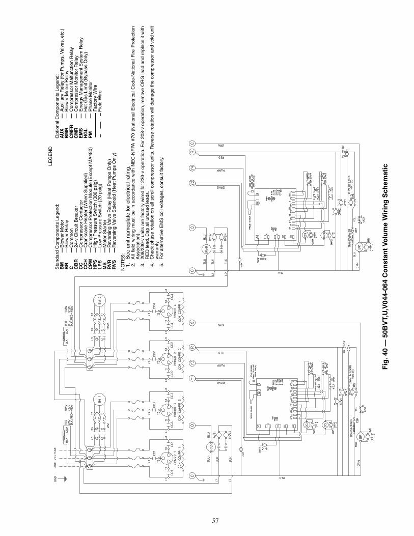
57
Fig
. 40
— 5
0BV
T,U
,V04
4-06
4 C
on
stan
t Vo
lum
e W
irin
g S
chem
aticLE
GE
ND
NO
TE
S:
1.S
ee u
nit n
amep
late
for
elec
tric
al r
atin
g.2.
All
field
wiri
ng m
ust
be i
n ac
cord
ance
with
NE
C-N
FPA
#70
(N
atio
nal
Ele
ctri
cal
Cod
e-N
atio
nal
Fire
Pro
tect
ion
Ass
ocia
tion)
.3.
208/
230-
v un
its a
re fa
ctor
y w
ired
for
230-
v op
erat
ion.
For
208
-v o
pera
tion,
rem
ove
OR
G le
ad a
nd r
epla
ce it
with
RE
D le
ad. C
ap a
ll un
used
lead
s.4.
Che
ck p
hase
rot
atio
n on
all
scro
ll co
mpr
esso
r un
its. R
ever
se r
otat
ion
will
dam
age
the
com
pres
sor
and
void
uni
tw
arra
nty.
5.F
or a
ltern
ativ
e E
MS
coi
l vol
tage
s, c
onsu
lt fa
ctor
y.
Sta
ndar
d C
ompo
nent
s Le
gend
:O
ptio
nal C
ompo
nent
s Le
gend
:B
M—
Blo
wer
Mot
orA
UX
—A
uxili
ary
Rel
ay (
for
Pum
ps, V
alve
s, e
tc.)
BR
—B
low
er R
elay
BM
R—
Blo
wer
Mot
or R
elay
C—
Com
mon
CM
FR
—C
ompr
esso
r M
alfu
nctio
n R
elay
CB
R—
24-v
Circ
uit B
reak
erC
MR
—C
ompr
esso
r M
onito
r R
elay
CC
—C
ompr
esso
r C
onta
ctor
EM
S—
Ene
rgy
Man
agem
ent S
yste
m R
elay
CC
H—
Cra
nkca
se H
eate
r (W
hen
Sup
plie
d)H
GL
—H
ot G
as L
imit
(Byp
ass
Onl
y)C
PM
—C
ompr
esso
r P
rote
ctio
n M
odul
e (E
xcep
t MA
480)
PM
—P
hase
Mon
itor
HP
S—
Hig
h P
ress
ure
Sw
itch
(380
psi
g) F
acto
ry W
ireL
PS
—Lo
w P
ress
ure
Sw
itch
(20
psig
) F
ield
Wire
MS
—M
otor
Sta
rter
RV
R—
Rev
ersi
ng V
alve
Rel
ay (
Hea
t Pum
ps O
nly)
RV
S—
Rev
ersi
ng V
alve
Sol
enoi
d (H
eat P
umps
Onl
y)
a50-7279ef
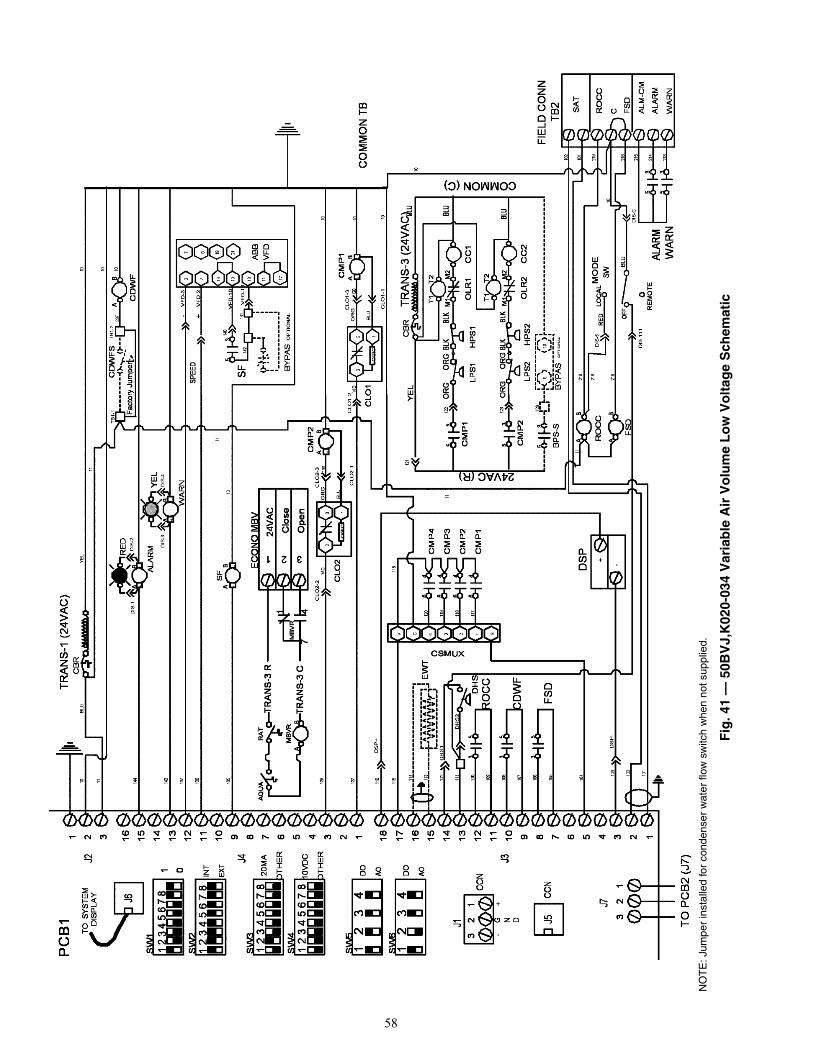
58
a50-
8236
Fig
. 41
— 5
0BV
J,K
020-
034
Var
iab
le A
ir V
olu
me
Lo
w V
olt
age
Sch
emat
ic
NO
TE
: Jum
per
inst
alle
d fo
r co
nden
ser
wat
er fl
ow s
witc
h w
hen
not s
uppl
ied.
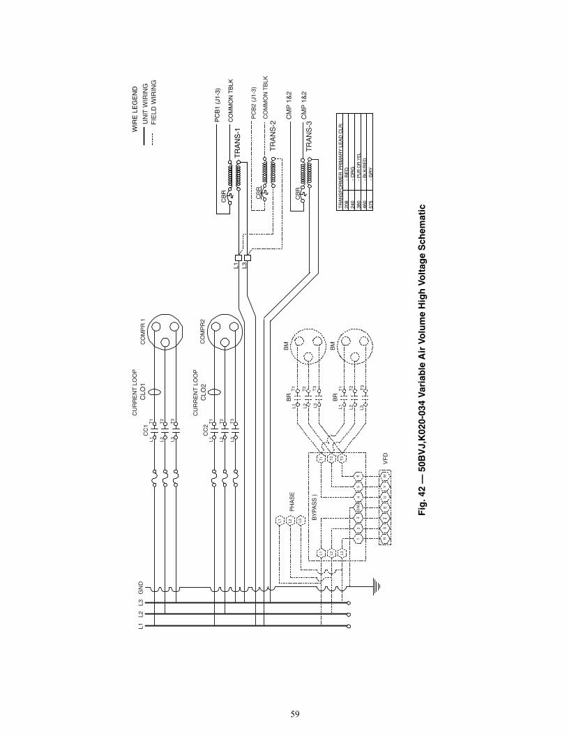
59
L1 L2 L3T
3
T2
CO
MP
R2
CLO
2C
UR
RE
NT
LO
OP
CC
2T
1
L3L2L1
CO
MP
R 1
CC
1
T2
T3
T1
CU
RR
EN
T L
OO
P
CLO
1
TR
AN
S-1
CB
RP
CB
1 (J
1-3)
CO
MM
ON
TB
LK
BM
BM
T2
L2 L3T
3
BR
L1T
1 T2
L2 L3T
3
BR
L1T
1
WV
FD
EU
VR
S
T2
T3
T1
13
2
BY
PA
SS
)
GN
D4
56
L3L1 L2
TR
AN
SF
OR
ME
R P
RIM
AR
Y L
EA
D C
LR:
- P
UR
OR
YE
L
- B
LK/R
ED
460
575
380
240
208
- G
RY
- O
RG
- R
ED
L1L2
L3G
ND
L3L2L1
PH
AS
E
L1 L3
PC
B2
(J1-
3)
CO
MM
ON
TB
LKC
BR
TR
AN
S-2
TR
AN
S-3
CM
P 1
&2
CB
RC
MP
1&
2
WIR
E L
EG
EN
D
UN
IT W
IRIN
GF
IELD
WIR
ING
T
a50-8215
Fig
. 42
— 5
0BV
J,K
020-
034
Var
iab
le A
ir V
olu
me
Hig
h V
olt
age
Sch
emat
ic

60
a50-
8237
NO
TE
: Jum
per
inst
alle
d fo
r co
nden
ser
wat
er fl
ow s
witc
h w
hen
not s
uppl
ied.
Fig
. 43
— 5
0BV
W,X
034-
064
Var
iab
le A
ir V
olu
me
Lo
w V
olt
age
Sch
emat
ic

61
L1T
1
L2T
2
L3T
3
CC
2C
OM
PR
2C
LO2
CU
RR
EN
T L
OO
P
L1 L2 L3T
3
T2
CO
MP
R 4
CLO
4C
UR
RE
NT
LO
OP
CC
4T
1
L1 L2 L3T
3
T2
CO
MP
R 3
CLO
3C
UR
RE
NT
LO
OP
CC
3T
1
L3L2L1
CO
MP
R 1
CC
1
T2
T3
T1
CU
RR
EN
T L
OO
P
CLO
1
TR
AN
S-1
CB
RP
CB
1 (J
1-3)
CO
MM
ON
TB
LK
TR
AN
S-4
CM
P 2
&4
CM
P 2
&4
CB
R
BM
BM
T2
L2 L3T
3
BR
L1T
1 T2
L2 L3T
3
BR
L1T
1
WV
FD
EU
VT
RS
T2
T3
T1
13
2
(BY
PA
SS
)
GN
D4
56
L3L1 L2
TR
AN
SF
OR
ME
R P
RIM
AR
Y L
EA
D C
LR:
- P
UR
OR
YE
L
- B
LK/R
ED
460
575
380
240
208
- G
RY
- O
RG
- R
ED
L1L2
L3G
ND
L3L2L1
PH
AS
E
L1 L3
PC
B2
(J1-
3)
CO
MM
ON
TB
LK
CB
R
TR
AN
S-2
TR
AN
S-3
CM
P 1
&2
or C
MP
1&
3C
BR
CM
P 1
&2
or C
MP
1&
3
WIR
E L
EG
EN
D
UN
IT W
IRIN
GF
IELD
WIR
ING
Fig
. 44
— 5
0BV
W,X
034-
064
Var
iab
le A
ir V
olu
me
Hig
h V
olt
age
Sch
emat
ic
a50-8238

62
TR
AN
S-2
(24
VA
C)
CB
R1 2 163 14 13 1215 5 46710 9 811 2 13 5 124 38 6710 913 12 111415161718
MA
_RA
FLT
S
35
TR
MO
P
CO
MM
ON
TB
23
1
TO
PC
B1
(J7)
J7
J3J4J1P
CB
2
1 2
3 4
5 6
7 8
SW
1
1 2
3 4
5 6
7 8
SW
2
1 2
3 4
5 6
7 8
SW
4
1 2
3 4
5 6
7 8
SW
3
1 2
3
4
1 2
3
4S
W6
SW
5
01
EX
T
INT
20M
A
OT
HE
R
OT
HE
R
10V
DC
AO
DO
AO
DO
+
TR
MO
P-
MS
R2
MS
R1
3 355
+
BLU
BP
S_S
-
TR
MC
T+
PH
AS
EP
HA
SE
RN
OC
CD
WF
AB
CD
WF
S
PH
AS
ER
35
35
BY
PA
S
FR
EE
Z
41 2
CO
MM
ON
24V
AC
0-20
MA
EC
ON
O M
odul
atin
g
HW
V
ALA
RM
WA
RN
ALM
-CM
HIR
FS
D
CRO
CC
TR
MC
T
VE
NT
R
TR
MO
P
SP
T
CRE
SE
T
TR
MC
T
53
53 3
5W
AR
NA
LAR
M
MS
R1
MS
R2
FS
D
RO
CC
AB
AB
AB B
A
RE
MO
TE
LOC
AL
OF
F
MO
DE
SW
TB
2F
IELD
CO
NN
TB
1-1
TB
1-2
YE
LB
LU
DIS
-7D
IS-8
+H
IR-
TR
AN
S-1
C
TR
AN
S-1
R
VE
NT
R
53
HIR
53
EC
ON
O O
PT
ION
BY
PA
SS
OP
TIO
N
DIS
-5
+
VE
NT
R-
AB
AB
ABB
A
AB
20 21 235
233
232
228
230
229
212
231
211
210
209
208
207
206
205
203
204
202
201
10
20
21
237
236
TB
1-3
235
232
11
233
234
10
207
210
10 228
227
226
225
224
223
222
221
220
219
1021
6
215
214
213
DIS
-6
11 1121
7
218
216
219
Fac
tory
Jum
per
JU
MP
ER
INS
TALL
ED
FO
R T
HIS
DE
VIC
E W
HE
N N
OT
SU
PP
LIE
D
BR
N
RE
D YE
L
BLU
TR
AN
S-1
CT
RA
NS
-1 R
1011
To 1
11
SA
T10
2
101
To P
CB
1
DIS
-CD
IS-1
11
31 2
24V
AC
Clo
se
Ope
n
EC
ON
O M
BV
TR
AN
S-3
R
TR
AN
S-3
C41
7MB
VR
AB
AB
MB
VR
RA
TA
QU
A
WIR
E L
EG
EN
DU
NIT
WIR
ING
FIE
LD W
IRIN
G
-
*
*
Fig
. 45
— 5
0BV
J,K
,W,X
Fie
ld-I
nst
alle
d L
ow
Vo
ltag
e S
chem
atic
(P
CB
2 M
od
ule
)
a50-7283ef

63
TR
AN
S-1
(24
VA
C)
CB
R1 2 163 14 13 1215 5 46710 9 811 2 13 5 124 38 6710 913 12 11141516
ALA
RM
RE
D
+-
+
WA
RN
-
- INO
UT
SP
EE
D
VIACC
P24 CC
S1 R
SF
53
BY
PA
S
VFD1
SF
+-
CM
P1
CLO
1LO
GIC
1
23
+-
CLO
2LO
GIC
2-
13+
CM
P2
1718
S13 24V C
EW
T
DH
S5
3
RO
CC
5
CD
WF
3
53
FS
D
46 6
4
64
64
CM
P1
CM
P2
CM
P3
CM
P4
+ -DS
P
TR
AN
S-3
(24
VA
C)
CB
R
HP
S1
LPS
1
53
CM
P1
M2
M1 O
LR1
CC
1
OLR
2C
MP
23M
1
CC
2
M2
BP
S-S
53
910
BY
PA
S
CO
MM
ON
TB
23
1
TO
PC
B2
(J7)
J7
J3J4J1
PC
B1
1 2
3 4
5 6
7 8
SW
1
1 2
3 4
5 6
7 8
SW
2
1 2
3 4
5 6
7 8
SW
4
1 2
3 4
5 6
7 8
SW
3
1 2
3
4
1 2
3
4S
W6
SW
5
01
EX
T
INT
20M
A
OT
HE
R
OT
HE
R
10V
DC
AO
DO
AO
DO
CSMUX
YE
L
DIS
-1D
IS-2
DIS
-3D
IS-4
YE
LB
LU
OP
TIO
NA
L
CLO
1-2
OP
TIO
NA
L
J6
TO
SY
ST
EM
DIS
PLA
Y
COMMON (C)
24VAC (R)
DIS
PLA
Y
AB
AB
AB
BA
BA
1010 14
4
143
137
136
135
10
139
138
140
142
129
CLO
2-2
CLO
2-1
CLO
2-3 13
0
127
CLO
1-1
CLO
1-3 12
810
116
115
115
120
119
118
117
114
113
111
112
109
110
108
107
106
105
104 10
3
102
101
121
122
512
3 126
11
VIO
OR
G
BLU
VIO
OR
G
BLU
RCFM
RY
IICC
CC
S1 F
VFD2
YE
L
OR
GO
RG
BLK
BLK
OR
GO
RG
BLK
BLK
BLU
BLU
BLU
F20
1 =
20
FN
SL
= 2
10
S9
S9
VF
D
+CN
OD
= 0
FN
OD
= 0
F10
3 =
0F
114
= 1
CN
OD
= 0
FN
OD
= 0
F10
3 =
0F
114
= 1
To O
FF
CC
VIA
141
P24
To T
B2
VF
D-C
C
VF
D-V
IA
VF
D-P
24
VF
D-S
1
LPS
2H
PS
2
DS
P+
DH
S2
DH
S1 D
SP
-
T1
T2
T1
T2
WIR
E L
EG
EN
DU
NIT
WIR
ING
FIE
LD W
IRIN
G
Fig
. 46
— 5
0BV
J,K
Fie
ld-I
nst
alle
d L
ow
Vo
ltag
e S
chem
atic
(P
CB
1 M
od
ule
)
a50-7285ef
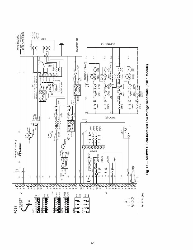
64
TR
AN
S-1
(24
VA
C)
CB
R1 2 163 14 13 1215 5 46710 9 811 2 13 5 124 38 6710 913 12 11141516
ALA
RM
RE
D
+-
+
WA
RN
-
- INO
UT
SP
EE
D
VIACC
P24 CC
S1 R
SF
53
BY
PA
S
VFD1
SF
+-
CM
P4
+-
2
13
CLO
4LO
GIC
CLO
3LO
GIC
2-
13+
CM
P3
CM
P1
CLO
1LO
GIC
1
23
+-
CLO
2LO
GIC
2-
13+
CM
P2
1718
S13 24V C
EW
T
DH
S5
3
RO
CC
5
CD
WF
3
53
FS
D
46 6
4
64
64
CM
P1
CM
P2
CM
P3
CM
P4
+ --DS
P
TR
AN
S-3
(24
VA
C)
CB
R
HP
S1
LPS
1
53
CM
P1
M2
M1 O
LR1
CC
1
CM
P3
LPS
3H
PS
3
53
OLR
3C
C3
M2
M1 O
LR4
OLR
2
CM
P4
CM
P2
HP
S4
LPS
4
HP
S2
3
LPS
2
M1
3M
1
CC
4
M2
CC
2
M2
BP
S-S
53
910
BY
PA
S
CO
MM
ON
TB
23
1
TO
PC
B2
(J7)
J7
J3J4J1
PC
B1
1 2
3 4
5 6
7 8
SW
1
1 2
3 4
5 6
7 8
SW
2
1 2
3 4
5 6
7 8
SW
4
1 2
3 4
5 6
7 8
SW
3
1 2
3
4
1 2
3
4S
W6
SW
5
01
EX
T
INT
20M
A
OT
HE
R
OT
HE
R
10V
DC
AO
DO
AO
DO
CSMUX
YE
L
DIS
-1D
IS-2
DIS
-3D
IS-4
YE
LB
LU
OP
TIO
NA
L
CLO
4-2
CLO
3-2
CLO
3-1
CLO
3-3
CLO
1-2
OP
TIO
NA
L
J6
TO
SY
ST
EM
DIS
PLA
Y
COMMON (C)
24VAC (R)
DIS
PLA
Y
AB
AB
AB
AB
AB
BA
BA
1010 14
4
143
137
136
135
10
139
138
140
142
133
129
CLO
2-2
131
132
CLO
4-1
CLO
4-3
CLO
2-1
CLO
2-313
4
130
127
CLO
1-1
CLO
1-3 12
810
116
115
115
120
119
118
117
114
113
111
112
109
110
108
107
106
105
104 10
3
102
101
121
122
124
512
3
512
5
126
11
VIO
OR
G
BLU
VIO
OR
G
BLU
VIO
OR
G
BLU
VIO
OR
G
BLU
RCFM
RY
IICC
CC
S1 F
VFD2
TR
AN
S-4
(24
VA
C)
CB
R
YE
L
YE
L
OR
GO
RG
BLK
BLK
OR
GO
RG
BLK
BLK
OR
GO
RG
BLK
BLK
OR
GO
RG
BLK
BLK
BLU
BLU
BLU
BLU
BLU
BLU
F20
1 =
20
FN
SL
= 2
10
S9
S9
VF
D
+CN
OD
= 0
FN
OD
= 0
F10
3 =
0F
114
= 1
CN
OD
= 0
FN
OD
= 0
F10
3 =
0F
114
= 1
To O
FF
CC
VIA
141
P24
To T
B2
VF
D-C
C
VF
D-V
IA
VF
D-P
24
VF
D-S
1
121
DS
P-
DH
S2
DH
S1
DS
P+
T1
T2
T1
T2
T1
T2
T1
T2
WIR
E L
EG
EN
DU
NIT
WIR
ING
FIE
LD W
IRIN
G
Fig
. 47
— 5
0BV
W,X
Fie
ld-I
nst
alle
d L
ow
Vo
ltag
e S
chem
atic
(P
CB
1 M
od
ule
)
a50-7286ef

65
LEGEND AND NOTES FOR FIG. 41-47
LEGEND
ALARM — Unit Alarm Relay (Critical Fault)ALM-CM— Alarm/Warning Relay CommonAO — Analog OutputAQUA — AquastatBM — Blower MotorBPS_S — Fan Start/Stop Relay (VFD Bypass Mode)BR — Blower RelayBYPAS — VFD Bypass ControlCBR — Circuit BreakerCC — Compressor ContactorCCN — Carrier Comfort Network®
CDWF — Condenser Waterflow RelayCDWFS — Condenser Waterflow SwitchCLO — Compressor Lockout ControlCMP — Compressor Control RelayCOMPR — CompressorCSMUX — Signal Multiplexer-Comp StatusDHS — Duct High Static Limit SwitchDO — Digital OutputDSP — Duct Static Pressure TransducerECONO — Economizer Valve/Damper ControlEWT — Entering Water Temperature SensorFLTS — Filter Status SwitchFREEZ — Freeze Thermostat (Water Economizer)FSD — Fire Alarm/ShutdownGND — GroundHIR — Heat Interlock RelayHPS — High Refrigerant Pressure Switch
LPS — Low Refrigerant Pressure SwitchMA_RA — Mixed/Return Air Temperature SensorMBVR — Motorized Ball Valve RelayMSR — Local/Remote Control RelaysOLR — Compressor Motor ProtectorPCB1 — Unit Control BoardPCB2,3 — I/O Expansion BoardPHASE — Phase/Rotation MonitorPHASER — Phase Monitor RelayRAT — Return Air ThermostatRESET — External ResetROCC — Remote OccupancySAT — Supply Air Temp. SensorSPT — Space/Zone Temperature SensorSF — Supply Fan Start/Stop RelaySPEED — 0-10 VDC Signal Isolator for VFDSW — SwitchT — TransformerTB2 — Terminal Block for Field ConnectionsTRANS — TransformerTRMCT — VAV Terminals ControlTRMOP — VAV Terminals OpenVENTR — Ventilation OutputVFD — Variable Frequency DriveWARN — Unit Warning Relay (Non-Critical Fault)
Factory WiringField Wiring
NOTES:1. Partial wiring shown on both power and control diagrams.2. Class 2 transformer TRANS-1 is wired into separate circuit. Do not interconnect other transformers or circuits; circuit
separation or compressor transformers from low voltage control panel transformers shall be maintained.3. Shielded wire shall have drain wire connected to VFD ground screw. The floating end of the drain wire shall be insulated.4. Shielded wire shall have drain wire connected to the control panel, adjacent to the PCB. The floating end of the drain
wire shall be insulated.

Manufacturer reserves the right to discontinue, or change at any time, specifications or designs without notice and without incurring obligations.Catalog No. 04-53500050-01 Printed in U.S.A. Form 50BV-4SI Pg 66 3-09 Replaces: 50BV-3SI
Copyright 2009 Carrier Corporation
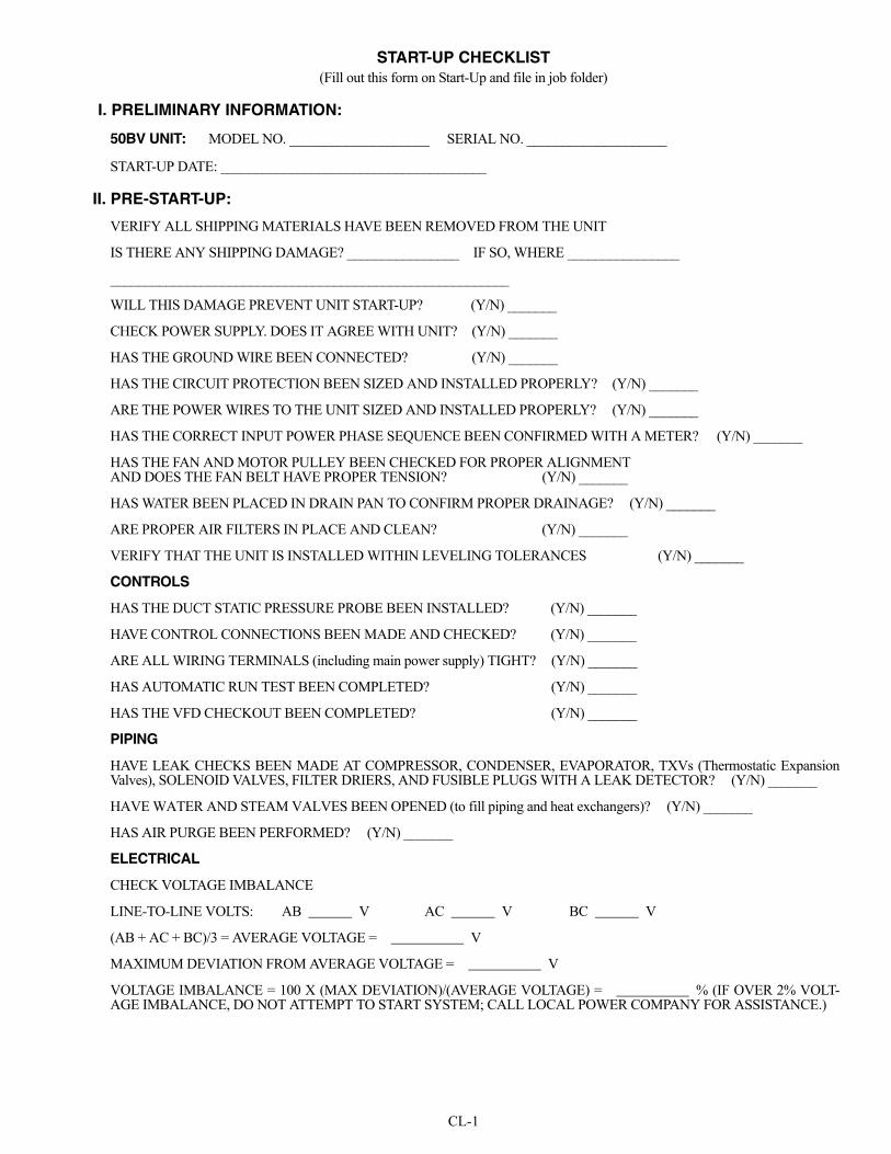
CL-1
START-UP CHECKLIST(Fill out this form on Start-Up and file in job folder)
I. PRELIMINARY INFORMATION:
50BV UNIT: MODEL NO. ____________________ SERIAL NO. ____________________
START-UP DATE: ______________________________________
II. PRE-START-UP:
VERIFY ALL SHIPPING MATERIALS HAVE BEEN REMOVED FROM THE UNIT
IS THERE ANY SHIPPING DAMAGE? ________________ IF SO, WHERE ________________
_________________________________________________________
WILL THIS DAMAGE PREVENT UNIT START-UP? (Y/N) _______
CHECK POWER SUPPLY. DOES IT AGREE WITH UNIT? (Y/N) _______
HAS THE GROUND WIRE BEEN CONNECTED? (Y/N) _______
HAS THE CIRCUIT PROTECTION BEEN SIZED AND INSTALLED PROPERLY? (Y/N) _______
ARE THE POWER WIRES TO THE UNIT SIZED AND INSTALLED PROPERLY? (Y/N) _______
HAS THE CORRECT INPUT POWER PHASE SEQUENCE BEEN CONFIRMED WITH A METER? (Y/N) _______
HAS THE FAN AND MOTOR PULLEY BEEN CHECKED FOR PROPER ALIGNMENT AND DOES THE FAN BELT HAVE PROPER TENSION? (Y/N) _______
HAS WATER BEEN PLACED IN DRAIN PAN TO CONFIRM PROPER DRAINAGE? (Y/N) _______
ARE PROPER AIR FILTERS IN PLACE AND CLEAN? (Y/N) _______
VERIFY THAT THE UNIT IS INSTALLED WITHIN LEVELING TOLERANCES (Y/N) _______
CONTROLS
HAS THE DUCT STATIC PRESSURE PROBE BEEN INSTALLED? (Y/N) _______
HAVE CONTROL CONNECTIONS BEEN MADE AND CHECKED? (Y/N) _______
ARE ALL WIRING TERMINALS (including main power supply) TIGHT? (Y/N) _______
HAS AUTOMATIC RUN TEST BEEN COMPLETED? (Y/N) _______
HAS THE VFD CHECKOUT BEEN COMPLETED? (Y/N) _______
PIPING
HAVE LEAK CHECKS BEEN MADE AT COMPRESSOR, CONDENSER, EVAPORATOR, TXVs (Thermostatic ExpansionValves), SOLENOID VALVES, FILTER DRIERS, AND FUSIBLE PLUGS WITH A LEAK DETECTOR? (Y/N) _______
HAVE WATER AND STEAM VALVES BEEN OPENED (to fill piping and heat exchangers)? (Y/N) _______
HAS AIR PURGE BEEN PERFORMED? (Y/N) _______
ELECTRICAL
CHECK VOLTAGE IMBALANCE
LINE-TO-LINE VOLTS: AB V AC V BC V
(AB + AC + BC)/3 = AVERAGE VOLTAGE = V
MAXIMUM DEVIATION FROM AVERAGE VOLTAGE = V
VOLTAGE IMBALANCE = 100 X (MAX DEVIATION)/(AVERAGE VOLTAGE) = % (IF OVER 2% VOLT-AGE IMBALANCE, DO NOT ATTEMPT TO START SYSTEM; CALL LOCAL POWER COMPANY FOR ASSISTANCE.)

Manufacturer reserves the right to discontinue, or change at any time, specifications or designs without notice and without incurring obligations.Catalog No. 04-53500050-01 Printed in U.S.A. Form 50BV-4SI Pg CL-2 7-12A 3-09 Replaces: 50BV-3SI
Copyright 2009 Carrier Corporation
- -
- -
- -
- -
- -
- -
- -
- -
- -
- -
- -
- -
- -
- -
- -
- -
- -
- -
- -
- -
- -
- -
- -
- -
- -
- -
- -
- -
- -
- -
- -
- -
- -
- -
- -
- -
- -
- -
- -
- -
- -
- -
- -
- -
- -
- -
- -
- -
- -
- -
- -
- -
- -
- -
- -
- -
- -
- -
- -
- -
- -
- -
- -
- -
- -
- -
- -
- -
- -
- -
- -
- -
- -
- -
- -
- -
- -
- -
- -
- -
- -
- -
- -
- -
- -
- -
- --
- -
- -
- -
- -
- -
- -
- -
- -
- -
-
CU
T A
LON
G D
OT
TE
D L
INE
CU
T A
LON
G D
OT
TE
D L
INE
III. START-UP:
CHECK FAN SPEED AND RECORD.
AFTER AT LEAST 15 MINUTES RUNNING TIME, RECORD THE FOLLOWING MEASUREMENTS:
COMPRESSOR AMPS:
NOTES: _______________________________________________________________________________________
_______________________________________________________________________________________________
_______________________________________________________________________________________________
_______________________________________________________________________________________________
CIRCUIT 1 CIRCUIT 2 CIRCUIT 3 CIRCUIT 4
SUCTION PRESSURE
SATURATED SUCTION TEMP
SUCTION LINE TEMP
SUPERHEAT DEGREES
DISCHARGE PRESSURE
SATURATED CONDENSING
LIQUID LINE TEMP
SUBCOOLING DEGREES
LIQUID SIGHT GLASS (CLEAR/BUBBLES)
ENTERING CONDENSER-WATER TEMP
LEAVING CONDENSER-WATER TEMP
EVAP ENTERING-AIR DB (dry bulb) TEMP
EVAP ENTERING-AIR WB (wet bulb) TEMP
EVAP LEAVING-AIR DB TEMP
EVAP LEAVING-AIR WB TEMP
L1
L2
L3
SUPPLY FAN AMPS:
L1
L2
L3