Installation & Software Guide - Amazon Web...
56
Version 2.4 SL-PEL Series Sectored Port Entry Light Installation & Software Guide
Transcript of Installation & Software Guide - Amazon Web...
Version 2.4
SL-PEL SeriesSectored Port Entry Light
Installation & Software Guide

Version No. Description Date Approved1.0 Manual Launch March 2014 D. Tomaszewicz2.0 Quick Start Guide April 2014 D. Tomaszewicz2.1 Quick Start Guide (wires) April 2014 D. Tomaszewicz2.2 Trouble Shooting July 2014 D. Tomaszewicz2.3 Update: Contact details & Spec table January 2016 J. Dore2.4 Update: PEL Config & Footer Sep 2016 B. Gielen
10o SL-PEL-10 Model
5o SL-PEL-05 Model
SL-PEL SeriesSectored Port Entry Light
SL-PEL SeriesSectored Port Entry Light
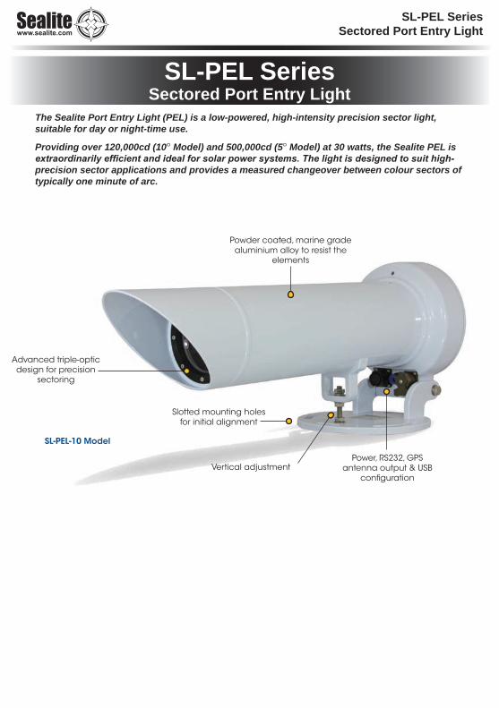
Advanced triple-optic design for precision
sectoring
Slotted mounting holes for initial alignment
Power, RS232, GPS antenna output & USB
configuration
Powder coated, marine grade aluminium alloy to resist the
elements
Vertical adjustment
SL-PEL-10 Model
The Sealite Port Entry Light (PEL) is a low-powered, high-intensity precision sector light, suitable for day or night-time use.
Providing over 120,000cd (10o Model) and 500,000cd (5o Model) at 30 watts, the Sealite PEL is extraordinarily efficient and ideal for solar power systems. The light is designed to suit high-precision sector applications and provides a measured changeover between colour sectors of typically one minute of arc.
SL-PEL SeriesSectored Port Entry Light
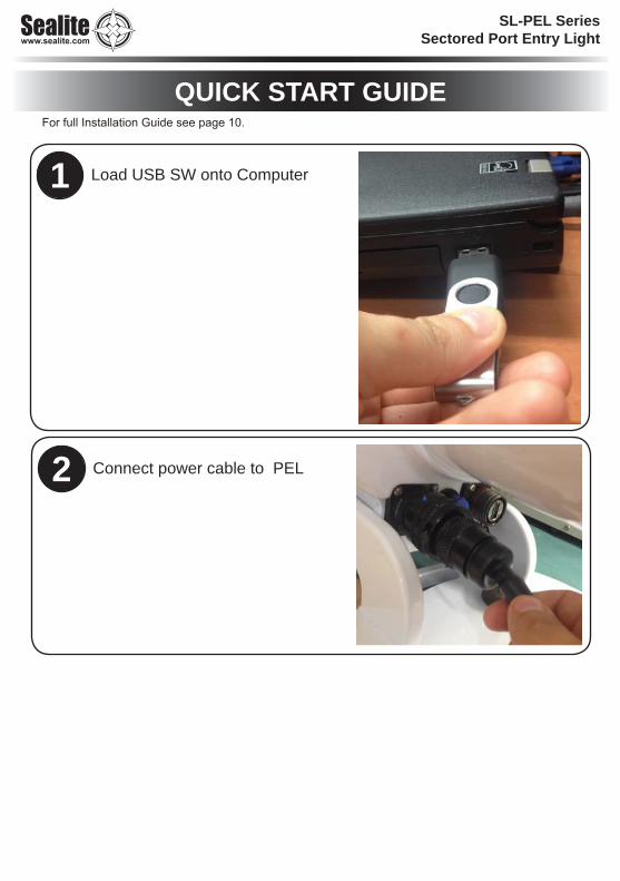
QUICK START GUIDE
Load USB SW onto Computer1
Connect power cable to PEL2
For full Installation Guide see page 10.
SL-PEL SeriesSectored Port Entry Light
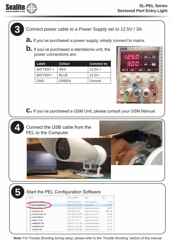
Connect power cable to a Power Supply set to 12.5V / 3A:
a. If you’ve purchased a power supply, simply connect to mains.
b. If you’ve purchased a standalone unit, the power connections are:
c. If you’ve purchased a GSM Unit, please consult your GSM Manual.
Connect the USB cable from the PEL to the Computer
Label Colour Connect to:BATTERY + RED 12.5V +
BATTERY - BLUE 12.5V -
GND GREEN Ground
3
4
Start the PEL Configuration Software5
Note: For Trouble Shooting during setup, please refer to the ‘Trouble Shooting’ section of this manual

Latest products and information available at www.sealite.com6
SL-PEL SeriesSectored Port Entry Light
Table of ContentsIntroduction ......................................................................................... Page 8
Technology .......................................................................................... Page 8
SL-PEL Series ..................................................................................... Page 9
INSTALLATION GUIDE ..................................................................... Page 10Prior to installation ....................................................................................... Page 10
Considering tower rigidity ........................................................................ Page 10Considering height .................................................................................. Page 10Considering tower colour ......................................................................... Page 10
Improving traditional leads with a PEL ......................................................... Page 11Considering daymarks ............................................................................. Page 11Considering twin or leading marks .......................................................... Page 11Night-time use ......................................................................................... Page 12Day-time use ........................................................................................... Page 12Day and night use ................................................................................... Page 12Considering site selection ....................................................................... Page 12Supporting aids ....................................................................................... Page 13Commissioning the PEL sector light ........................................................ Page 13Alignment of the PEL Sector light ............................................................ Page 14Final sea check ....................................................................................... Page 17Synchronisation with other aids ............................................................... Page 17
Care and handling of the PEL ......................................................... Page 18
SOFTWARE GUIDE ........................................................................... Page 19
USB interface setup ......................................................................... Page 19
Info tab ............................................................................................... Page 22Name ........................................................................................................... Page 22LED Colours ................................................................................................. Page 22Event Log ..................................................................................................... Page 23
Operation Mode tab .......................................................................... Page 24Operation Mode Settings ............................................................................. Page 24Factory Reset ............................................................................................... Page 25
Intensity tab ...................................................................................... Page 26Adjusting Intensities ..................................................................................... Page 26Viewing Adjusted Intensities ........................................................................ Page 27

Latest products and information available at www.sealite.com7
SL-PEL SeriesSectored Port Entry Light
Flash Code tab .................................................................................. Page 28Setting flash codes ....................................................................................... Page 28Custom flash codes ..................................................................................... Page 29
Sensor tab ......................................................................................... Page 30Battery Sensor ............................................................................................. Page 30
Changing Battery Thresholds .................................................................. Page 31Disabling/Enabling Low Battery Voltage Options .................................... Page 31
Temperature Sensor .................................................................................... Page 32Changing Temperature Thresholds ......................................................... Page 32Disabling/Enabling Temperature Threshold Options ............................... Page 33
LED Sensor (LED Diagnostics) .................................................................... Page 34Disabling/Enabling Alarm Options ........................................................... Page 34
Light Sensor ................................................................................................. Page 36Managing Light Sensor Thresholds ......................................................... Page 37Changing Light Thresholds ..................................................................... Page 37
Advanced tab .................................................................................... Page 38Lantern Information ...................................................................................... Page 38Lantern Setup .............................................................................................. Page 39Intensity ........................................................................................................ Page 40
Changing LED Intensities ........................................................................ Page 40Flashcode .................................................................................................... Page 41Sync Offset .................................................................................................. Page 41
Writing LED Synchronisation ................................................................... Page 41
AIS tab ............................................................................................... Page 42
GPS Synchronisation ....................................................................... Page 43
Examples of PEL Beam Configurations ......................................... Page 45
Flash Codes ...................................................................................... Page 46
Optional GSM Cell Phone Monitoring & Control ........................... Page 51
Maintenance and Servicing ............................................................. Page 52
Trouble shooting .............................................................................. Page 53
PEL Warranty Statement .................................................................. Page 53Sealite LED Light Warranty ............................................................. Page 54

Latest products and information available at www.sealite.com8
SL-PEL SeriesSectored Port Entry Light
IntroductionCongratulations! By choosing to purchase a Sealite Sectored Port Entry Light you have become the owner of one of the most advanced LED marine lights in the world.Sealite Pty Ltd has been manufacturing lanterns for over 25 years, and particular care has been taken to ensure your lantern gives years of service.As a commitment to producing the highest quality products for our customers, Sealite has been independently certified as complying with the requirements of ISO9001:2008 quality management system.By taking a few moments to browse through this booklet, you will become familiar with the versatility of your light, and be able to maximise its operating function.
TechnologySealite is the world’s fastest growing manufacturer of marine aids to navigation. We employ leading mechanical, optical, hardware & software engineers to create innovative products to service the needs of our customers worldwide, and offer the widest range of solar-powered LED lanterns in the marketplace. ElectronicsSealite employs leading in-house electronic engineers in the design and development of software and related circuitry. All individual electronic components are sourced directly by Sealite procurement staff ensuring that only the highest quality components are used in our products.
LED TechnologyAll marine lanterns use the latest advancements in LED (Light Emitting Diode) technology as a light source. The major advantage of LED’s over traditional light sources is well established in that they typically have an operational life in excess of 100,000 hours, resulting in substantial savings to maintenance and servicing costs.
Precision Construction Commitment to investing in the design and construction of injection-moulded parts including optic lenses, light bases and a range of other components ensures that all Sealite products are of a consistent & superior quality.
Optical PerformanceSealite manufactures a range of marine LED lenses moulded from multi-cavity dies. The company has superior in-house lens manufacturing capabilities to support outstanding optical performance.
Award-winning, Patented Technology Several United States and Australian patent registrations are held on Sealite’s range of innovative designs, with other regional patents pending in Canada, United Kingdom and Europe.
• Sp
ec
ifica
tion
s sub
jec
t to c
ha
ng
e o
r varia
tion
with
ou
t no
tice
* Su
bje
ct to
stan
da
rd te
rms a
nd
co
nd
ition
s§ W
hite
inte
nsity c
an
be
ba
lan
ce
d w
ith c
olo
ure
d in
ten
sity or in
cre
ase
d to
ma
tch
histo
rica
l filam
en
t lan
tern
pe
rform
an
ce
Latest products and information available at www.sealite.com9
SL-PEL SeriesSectored Port Entry Light
SL-PEL Series
• Sp
ec
ifica
tion
s sub
jec
t to c
ha
ng
e o
r varia
tion
with
ou
t no
tice
* Su
bje
ct to
stan
da
rd te
rms a
nd
co
nd
ition
s§ W
hite
inte
nsity c
an
be
ba
lan
ce
d w
ith c
olo
ure
d in
ten
sity or in
cre
ase
d to
ma
tch
histo
rica
l filam
en
t lan
tern
pe
rform
an
ce
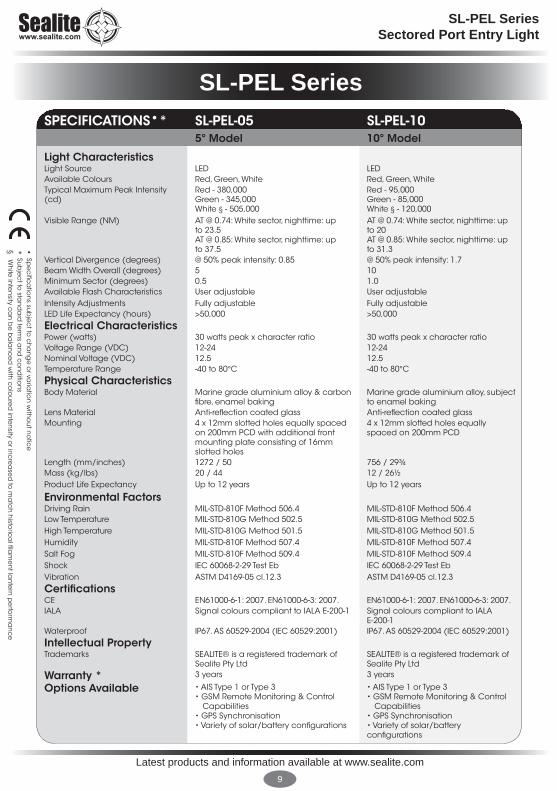
SPECIFICATIONS•* SL-PEL-05 SL-PEL-105o Model 10o Model
Light CharacteristicsLight Source LED LEDAvailable Colours Red, Green, White Red, Green, WhiteTypical Maximum Peak Intensity (cd)
Red - 380,000Green - 345,000White § - 505,000
Red - 95,000Green - 85,000White § - 120,000
Visible Range (NM) AT @ 0.74: White sector, nighttime: up to 23.5 AT @ 0.85: White sector, nighttime: up to 37.5
AT @ 0.74: White sector, nighttime: up to 20AT @ 0.85: White sector, nighttime: up to 31.3
Vertical Divergence (degrees) @ 50% peak intensity: 0.85 @ 50% peak intensity: 1.7Beam Width Overall (degrees) 5 10Minimum Sector (degrees) 0.5 1.0Available Flash Characteristics User adjustable User adjustableIntensity Adjustments Fully adjustable Fully adjustableLED Life Expectancy (hours) >50,000 >50,000
Electrical CharacteristicsPower (watts) 30 watts peak x character ratio 30 watts peak x character ratioVoltage Range (VDC) 12-24 12-24Nominal Voltage (VDC) 12.5 12.5Temperature Range -40 to 80°C -40 to 80°C
Physical CharacteristicsBody Material Marine grade aluminium alloy & carbon
fibre, enamel bakingMarine grade aluminium alloy, subject to enamel baking
Lens Material Anti-reflection coated glass Anti-reflection coated glass Mounting 4 x 12mm slotted holes equally spaced
on 200mm PCD with additional front mounting plate consisting of 16mm slotted holes
4 x 12mm slotted holes equally spaced on 200mm PCD
Length (mm/inches) 1272 / 50 756 / 29¾Mass (kg/lbs) 20 / 44 12 / 26½Product Life Expectancy Up to 12 years Up to 12 years
Environmental FactorsDriving Rain MIL-STD-810F Method 506.4 MIL-STD-810F Method 506.4Low Temperature MIL-STD-810G Method 502.5 MIL-STD-810G Method 502.5High Temperature MIL-STD-810G Method 501.5 MIL-STD-810G Method 501.5Humidity MIL-STD-810F Method 507.4 MIL-STD-810F Method 507.4Salt Fog MIL-STD-810F Method 509.4 MIL-STD-810F Method 509.4Shock IEC 60068-2-29 Test Eb IEC 60068-2-29 Test EbVibration ASTM D4169-05 cl.12.3 ASTM D4169-05 cl.12.3
CertificationsCE EN61000-6-1: 2007. EN61000-6-3: 2007. EN61000-6-1: 2007. EN61000-6-3: 2007. IALA Signal colours compliant to IALA E-200-1 Signal colours compliant to IALA
E-200-1Waterproof IP67. AS 60529-2004 (IEC 60529:2001) IP67. AS 60529-2004 (IEC 60529:2001)
Intellectual PropertyTrademarks SEALITE® is a registered trademark of
Sealite Pty LtdSEALITE® is a registered trademark of Sealite Pty Ltd
Warranty * 3 years 3 years
Options Available • AIS Type 1 or Type 3• GSM Remote Monitoring & Control
Capabilities• GPS Synchronisation• Variety of solar/battery configurations
• AIS Type 1 or Type 3• GSM Remote Monitoring & Control
Capabilities• GPS Synchronisation• Variety of solar/battery configurations

Latest products and information available at www.sealite.com10
SL-PEL SeriesSectored Port Entry Light
CONSIDERING TOWER RIGIDITY:It is important to remember that the PEL sectored light has a precision of typically one min of arc and any structure or mounting bracket used to support it must have that rigidity in terms of horizontal twist.
When considering the PEL’s mounting, the following items need to be reviewed if these structures will be utilised: size of daymark, its age, ladder and platform access. In addition, while the light-weight nature of the PEL will permit mounting on a tilted column, its slender nature and the need to align the light when fully erect precludes its use.
The structure must therefore be able to support the following: the PEL itself, its required power supply, any daymarks, and at least two maintenance staff without twisting in heavy gale force winds (up to 100 MPH).
CONSIDERING HEIGHT:The height of the structure above chart datum must suit not only the tallest bridge height but also the smallest bridge height during all states of the tide, and not only at the extremity of the channel, but from the nearest point of exit or to that point where other port lights take over. This is a function of the vertical divergence of the PEL and the centre line of the PEL can be arranged to point into mid-channel, ensuring that the top of the beam to 50% equates to the tallest bridge height on the largest tide. The reverse is true for the smallest vessel on the lowest tide and the point of exit. Sealite engineers can offer advice in this regard upon request.
CONSIDERING TOWER COLOUR:In most cases the PEL sector light will supplement an existing mark which may be a well-recognised building, solid stone tower, or steel lattice construction. It could be that the nature and type of use of this structure and surrounding background has changed over the years. While the PEL itself will enhance and improve the structures identification in day time, it is important to review.
Perhaps the original building or structure was white when viewed against a jungle or sloping green fields and with modern build up around the port it is now surrounded by concrete buildings or tanks. During project review and implementation a simple inbound trip on the pilot or suitable vessel whilst taking pictures at one mile intervals will reveal many simple opportunities for further enhancement. Changing the tower colour or adding colour to the structure will assist the mariner in improving its recognition. It is not essential to retain its original colour just because it has always been so.
INSTALLATION GUIDEThank you for choosing a Sealite SL LED series precision sector light. The unit has been pre-programmed to suit your order which includes the colour of each sector. All other parameters are user programmable. These parameters have been factory set.
Prior to installation
Latest products and information available at www.sealite.com11
SL-PEL SeriesSectored Port Entry Light
CONSIDERING DAYMARKS: While the PEL will be used as a single station aid, this does not mean that daymarks are no longer required. For example, a steel lattice tower or single column pole will be almost invisible from seaward. By cladding the tower in vertical or horizontal boards its recognition will improve in daylight hours. Its colour should be in contrast to the normal back ground.
If this is an established approach bearing, most pilots and masters will have their own “back-marks” to create a natural leading line if no back-mark exists. This could be a church or mosque spire, telecoms tower, natural dip in a mountainous sky line, or even a mountain or hill itself. It could however just be another building.
Natural marks or buildings owned by others are unable to be enhanced, however buildings owned by the ports themselves can have daymark squares painted on their edges to improve the bearing line recognition. Again, by taking a series of pictures on the approach line can improve this process and Sealite engineers can offer recommendations.
These additions and suggestions to the project are usually very cost-effective in enhancing the PEL performance and an age old proven method of assisting the mariner which can sometimes be overlooked when considering the overall project.
CONSIDERING TWIN OR LEADING MARKS:While the PEL is predominately used as a single station aid, they should be retained as an unlit structure to assist day use if a “back-mark” or “front-mark” exists where the bearing line is still relevant, provided there is no significant cost to its retention.
If it is the “back-mark” that is to be retained, consideration should be given to supplementing this mark with an omni-directional light synchronised to the PEL. Even if the channel has been extended, destroying the sensitivity of the system, keeping a light synchronised with the sectored light is another way of maintaining the approach to the bearing line. This is true of whether the structure is to be lit or to remain unlit.
The “series of pictures” method can be extended to include approach to the bearing line noting beacons and buoys used in the passage of which further mention will be made later in this manual.
Improving traditional leads with a PEL

Latest products and information available at www.sealite.com12
SL-PEL SeriesSectored Port Entry Light
NIGHT-TIME USE:Usually one of the main reasons a port considers upgrading its leading line is due to a growth of port infrastructure around the bearing, making it impossible for the mariner to pick out the leads. Again, a photographic record of an approach noting possible interfering lights at night time will help to enhance the new system. A simple addition of flood lights or an adjustment of current flood light direction could improve recognition significantly. This exercise is also useful when determining the level of automatic night dimming which will be discussed later in the manual.
DAY-TIME USE:Providing a light for day use is expensive in terms of the power required to generate bright lights which is visible in daytime. Reference to the approach bearing will determine if this is to be directly in a rising or setting sun. Any viewing in this direction without the assistance of a dark skyline will reduce the range of the light. The higher the mountain range or building behind the light which will create a large silhouette will increase the range the light can achieve. Summer and winter variations of the sun’s position relative to the bearing angle should also be considered.
It is recommended that during the project’s engineering stage that a series of pictures are taken of the ship’s view during approach during the time of a rising or setting sun, or any other harsh conditions to make a valid assessment of light intensity required. Sealite engineers may also be consulted for their recommendations.
DAY AND NIGHT USE: If the light is to be used in both day and night time applications it will most certainly require to be dimmed for night use. This is an automatic feature built into the PEL where the user can configure the intensities to be set. Sealite engineers have created a programme supplied with the PEL which enables the commissioning engineer to adjust this intensity via the USB port provided.
CONSIDERING SITE SELECTION:If the project is brand new with a new bearing line and the Harbour Master or Pilots have a choice to select the approach line over and above any geographical restrictions on the position of rocks or reefs, it is a useful exercise to draw the “ideal approach line.” This could be angled to suit a particular approach if vessels will always approach from a given direction. If from either Port or Starboard of the line then the line will need to be centralised. However, if the approach for a given size of vessel is always from the Port side of the bearing line then the line should be angled to diminish his course change. Amounts of dredging (if required) is always an item to be taken into consideration in terms of cost.
Once selected, the extremity of the channel or to the edge of any rocks or reefs should be drawn on either side of this bearing line. These lines should be extended back to shore or the location from which the PEL will be driven. Once the points have been selected, the land or sea within these two vectors can be reviewed for suitability. Points to be considered include:
1. Ownership of the land.
2. Background on the leading line.

Latest products and information available at www.sealite.com13
SL-PEL SeriesSectored Port Entry Light
3. Obstructions in front of any position selected.
4. Height of that point naturally above Chart Datum.
5. Light pollution around this spot.
6. Any shadows which will affect solar applications.
Through a combination of suitability and cost implications a theoretical position can be determined and proposed to define safe passage through the channel and any obstacles. This latitude and longitude point should be recorded and filled into the Sealite PEL Information Checklist and sent to Sealite to aid discussions.
SUPPORTING AIDS:Previously, Aids to Navigation (AtoNs) were considered stand-alone devices due to restrictions on technology. With the improvements of radio and satellite communications however, it is now possible to link these previous stand-alone aids. This is true for buoy synchronised channels and pairs of leading lights, as well as channels and isolated buoys on leading line approaches.
It is now possible to select leads to be synchronised with specific beacons and buoys to increase the mariner’s total field of vision in one time during approach. By revisiting the flash characters of previously isolated aids it is now possible to create better approaches and combine these isolated beacons and buoys to the approach character of the leading or sectored light.
Here again Sealite can assist in offering recommendations to enhance the approach to the leading bearing. There are distinct advantages in reviewing supporting aids to enhance the overall marking of the port and to save on power consumption. This can help increase the range of these aids to offset the ever increasing background lighting in a port.
COMMISSIONING THE PEL SECTOR LIGHT:Prior to installation it is recommended that the relative position of the site be checked against both the charts and other prominent navigation marks used around the port. These can be breakwater or quay edges, and church spires or lighthouses which have specific points of sight (i.e.: wind vanes and masts). These can be used to check the relative bearing angle to each other and ensure the proposed leading line is correct.
It is not unusual to discover small inaccuracies of charted rocks or quay extensions from those currently on the chart due to the date and accuracy of the most recent surveys.
Latest products and information available at www.sealite.com14
SL-PEL SeriesSectored Port Entry Light
ALIGNMENT OF THE PEL SECTOR LIGHT:While there is no best single method of achieving a commissioned alignment, there are many variants on how alignment may be achieved. The PEL sector light is an accurate instrument but it should be noted that the centre line of the beam is theoretical, and the only points of accurate reference are the edges of the total beam (light cut off) or between colours. It is these reference lines which should be used to set up the light and these bearing lines should be drawn on the chart and bearings noted.
Option 1 (Preferred method)
Refer to the chart and select known defined points on land at a distance of approximately 1/2 to 3/4 of a mile from the sectored light. This may be the edge of a quay or rock with established beacon which is identifiable on the chart from which a distance to one of the bearing lines can be measured by tape over land. This point can be determined prior to the installation and marked by a wooden peg or spray painted spot on a rock or quay wall.
Option 2
If such a point is not available over land, the same can be achieved using a measure line of Polypropylene floating rope which can be laid out from a small boat and held in tension in a given direction previously determined from the chart.
Option 3
If none of the bearing lines make land fall or the distance from land is greater than 100 to 200 metres then the operation of alignment must be conducted dynamically by boat with reference to a Theodolite alignment. Method 3 will require the Theodolite to be set up at the base of the tower directly below the light on the centre line of the theoretical bearing or on the balcony of the tower itself. It must be on the centre line of the approach with reference to all other local marks.
Clear Line of Sight
The position selected must have a clear line of sight of the bearing lines on the day of alignment and not be obstructed by any vessel.
Time of Alignment
The best time to align the light is when light levels are at their softest (early morning or dusk). Viewing the light in the direction of a rising and setting sun should be avoided and a time selected where the tide suits those marks which have been selected for reference. This is important in areas with high tidal ranges, both for access to the mark and draft of the vessel (if used to get to the location).
Personnel required
At the reference point:
One competent observer with VHF radio or mobile phone who can communicate in the same language as the commissioning technician without the need of a translator.

Latest products and information available at www.sealite.com15
SL-PEL SeriesSectored Port Entry Light
If Method 2 or 3 is being used, a small motor powered boat with both helmsman and able-bodied seamen to lay out the line and act as a safety man. The observer must be free of all duties and concentrate only on reporting what he can see.
At the PEL:
One technician with VHF radio or GSM phone if methods 1 or 2 are being utilised.
If method 3 is being used, a skilled Theodolite operator with shared VHF radio.
Approximately 1 hour should be allowed for Method 1 and 2-3 hours for Methods 2 or 3 ensuring that all operations are complete before the hours of darkness. All parties should gather for a discussion on what is required of each person. It is recommended that the acceptance officer who will endorse the alignment of the light is positioned at the light during alignment. They may verify the completed alignment from seaward at a later time, however acceptance and verification shall be completed at the tower.
Alignment Procedure:
It is recommended that the lantern is set to a fixed flash character (00) and 100% intensity with the PEL set to the required operation mode. Be mindful of covering the light sensor when testing night conditions. To set this, refer to the programming section in the manual.
Methods 1 and 2:
1. With the observer in position, switch on the PEL. Both the observer and technician should be in voice contact.
2. Swing the light around until the observer sees the light. It is not important which colour he sees. The observer should report the colour.
3. The PEL can now be loosely tightened down to its fixings.
4. Depending on colour seen, the technician can determine whether the light has to be moved to the right or left.
a. Method 1: by instruction from the tower the observer can be asked to walk to the left or right to determine how much the light is off the mark and inform the tower.
b. Method 2: by instruction from the tower the boat can be asked to be moved to the left or right to determine how much the light is off the mark and inform the tower.
5. Using electrical tape and a pen mark the original position on the flange of the light.
6. The light can now be loosened and adjusted.
7. By repeating the adjustments in small increments, the light can gradually be moved until the observer on the mark can move in and out of the colour boundary selected by moving his head to the left and right by approximately 300 mm.
8. When the technician and acceptance officer are satisfied, the light may be tightened into position.

Latest products and information available at www.sealite.com16
SL-PEL SeriesSectored Port Entry Light
Method 3:
NOTE: During the alignment process using Method 3, port traffic should be held from passage.
1. The helmsman of the boat MUST accept all instructions from the Theodolite operator. The Observer MUST stay in a single fixed position on the vessel in clear view of the tower. It is suggested to assist in his recognition that he stand alone or wear a High-VIS vest of a different colour than all other staff to remain clearly visible.
2. The vessel will position himself at either 1/2 to 1 mile range from the tower on the approximate bearing line and await instructions.
3. The Theodolite operator will use the telescope to find the observer
4. With the light switched on the Theodolite operator will instruct the vessel to make a slow passage perpendicular to the bearing line.
5. The observer will call on the radio e.g.: “Nothing, nothing, nothing, red” and then remove his finger from the transmission button. At this point the vessel stands awaiting further instructions.
6. The Theodolite operator can then work out the approximate position of the light and instruct the technician to move the light accordingly in a given direction.
7. It is recommended that if this position is very near the final position that no adjustment be made on the first passage. Instead, the vessel should be instructed to come about and proceed on a reciprocal bearing to last followed and repeat the procedure. (It should be noted that during this time the vessel may have drifted and the observer may call “red, red, red” for a long period until he calls nothing. This is to be expected but should he call a colour change at the same point and the light can then be moved accordingly.)
8. After a number of passes the team will achieve alignment. NOTE: The speed of the vessel will need to be tuned to tide movements and in the final stages this should be a nearly stopped passage.
9. Prior to final tightening of the PEL the process should be repeated for another boundary check.
10. When the technician and acceptance officer are satisfied, the light may be fully tightened into position.
Horizontal Alignment:
During the alignment it may be necessary to angle the beam of the light towards the observer especially if conducted in a small boat. This should be performed by adjusting the adjustment screw beneath the barrel and locked as pictured. A small spirit level placed on the barrel will assist.

Latest products and information available at www.sealite.com17
SL-PEL SeriesSectored Port Entry Light
FINAL SEA CHECK:It may be necessary to make a night passage to determine if the automatic night dimming level selected suits the port and its particular night-time background light.
This is particularly important while making the approaches to the sector light as the port’s flood light or any nearby lighting drown the mark as they pass behind the sector light. The Harbour Master or Pilots representative must realise that the light is adjustable and setting a high intensity to assist in long range identification may perhaps destroy night vision at close range. It is therefore a compromise as the operators become accustomed to this aid that intensities are not fixed in stone and adjustable.
Pilots and Masters will use their own personal marks during both day and night passages to verify the accuracy of the new aid before they become comfortable with the new addition. In order to make the most of the PEL, it is necessary to stand in a single position on the bridge without moving from Port to Starboard. If it is necessary for observations to be made from another point, it is important to remember only to observe the light from a given point to get a consistent indication of position.
SYNCHRONISATION WITH OTHER AIDS:It may be part of the scheme to synchronise the PEL with other aids.
If an identification light on the same structure is employed it may be switched on after alignment. The distance of vertical separation should be selected depending on its purpose.
If the identification light has a sector complimenting and extending the PEL boundaries, this should be positioned on the centre line within 500mm vertically below the PEL.
If it is an omnidirectional light of a different colour intended to be seen separately from the sector, it should be positioned (ideally) on the centre line, or at least between 3 and 6 metres below the sector depending on range.

Latest products and information available at www.sealite.com18
SL-PEL SeriesSectored Port Entry Light
Care & handling of the PELSpecial care should be taken when handling the Port Entry light. Optics can be easily damaged from poor handling and incorrect cleaning methods. Be sure to consider the following guidelines:
- The PEL has been supplied in suit packing. Upon arrival of the PEL, inspect for any damage and immediately notify the carrier. Goods should bot be signed for without unpacking and checking for damage
- Retain Sealite packing for safe transportation of the PEL to the tower.
- Never place hard or rough surfaces on PEL optics as the lens can be easily scratched and chipped.
- Optics should never be handled with bare fingers as oils from the skin may remove and damage coated and uncoated surfaces.
- Use only lint-free cloths or lens tissue when cleaning surface of the PEL lens.
- Apply isopropyl alcohol (IPA) directly to your cloth – NEVER directly to the lens. Use slow, even, light pressure working from edge to edge across the PEL Lens allowing IPA to evaporate.
- If storing the PEL ensure the optics and connectors are protected.
Latest products and information available at www.sealite.com19
SL-PEL SeriesSectored Port Entry Light
SOFTWARE GUIDE
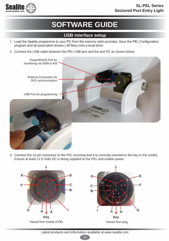
1. Load the Sealite programme to your PC from the memory stick provided. Save the PEL Configuration program and all associated drivers (.dll files) onto a local drive.
2. Connect the USB cable between the PEL USB port and the test PC as shown below:
3. Connect the 10 pin connector to the PEL ensuring that it is correctly oriented to the key in the socket. Ensure at least 12.5 Volts DC is being supplied to the PEL and enable power.
Power/RS232 Port for monitoring via GSM or AIS
Antenna Connection for GPS synchronisation
USB Port for programming
Viewed from socket of PEL
AKey
E
F
G H
D
C
I
B
J
Viewed from plug
HKey
D
C
I A
E
F
G
J
B
USB interface setup
Latest products and information available at www.sealite.com20
SL-PEL SeriesSectored Port Entry Light
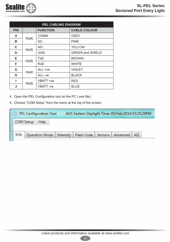
4. Open the PEL Configuration tool on the PC (.exe file).
5. Choose “COM Setup” from the menu at the top of the screen.
PEL CABLING DIAGRAMPIN FUNCTION CABLE COLOURA
PAIRCOMM GREY
B NC PINK
CPAIR
NO YELLOW
D GND GREEN and SHIELD
EPAIR
TxD BROWN
F RxD WHITE
GPAIR
ALL +ve VIOLET
H ALL -ve BLACK
IPAIR
VBATT +ve RED
J VBATT -ve BLUE

Latest products and information available at www.sealite.com21
SL-PEL SeriesSectored Port Entry Light
6. Select the name of the desired COM port from the list. If you do not know the COM port, use the Windows Device Manager to find out the COM port number as shown below.
7. With the com port selected, set the baud rate to 9600 and press the OK button.
Note: If COM port fails to connect, please refer to the ‘Trouble Shooting’ section of this manual.

Latest products and information available at www.sealite.com22
SL-PEL SeriesSectored Port Entry Light
Info tabWith power applied and USB connected the picture of the PEL below will start to progressively show the colours and orientation of the LEDS that have been configured on the card. If the picture is not showing coloured beams the PC is not connected to the programme via the COM port selected and the port selection process will need to be repeated.
Press the Info tab. Within 10 seconds the software version and hardware type will be displayed.
NAMEBy default there is no name for the PEL. The user may enter one by entering text and clicking ‘Write.’
LED COLOURS
The LED colours are shown together with their orientation for each LED.
This orientation is selected at the time of order and is dependent on whether the Unit will be used in an IALA Buoyage System A (rest of the World) area or Buoyage System B (Americas and Japan).
(Note: The flashing character is representational only and NOT the programmed code of the unit.)
Latest products and information available at www.sealite.com23
SL-PEL SeriesSectored Port Entry Light
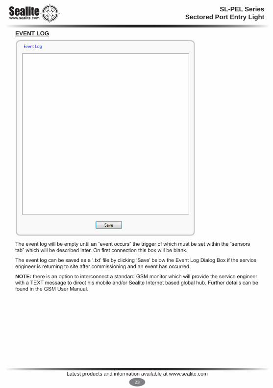
EVENT LOG
The event log will be empty until an “event occurs” the trigger of which must be set within the “sensors tab” which will be described later. On first connection this box will be blank.
The event log can be saved as a ‘.txt’ file by clicking ‘Save’ below the Event Log Dialog Box if the service engineer is returning to site after commissioning and an event has occurred.
NOTE: there is an option to interconnect a standard GSM monitor which will provide the service engineer with a TEXT message to direct his mobile and/or Sealite Internet based global hub. Further details can be found in the GSM User Manual.

Latest products and information available at www.sealite.com24
SL-PEL SeriesSectored Port Entry Light
Internal light sensor
Operation Mode tabThe PEL configuration tool will automatically read the current operation mode of the PEL on start-up and is displayed above the “Write button”.
OPERATION MODE SETTINGSThe current operation mode of the PEL is displayed above the “Write” button. The default operation mode is “Dusk to Dawn”.
To change the Operation Mode, select one of the following options from the drop down menu and click ‘Write’:
• Always On - All LEDs will turn on with Night Intensity• Standby - All LEDs will be turned off• *Day and Night - All LEDs will turn on with Day Intensity
- Night Intensity (when light levels are low)- Day Intensity (when light levels are high)
• *Dusk Till Dawn - All LEDs will turn on with Night Intensity (when light levels are low) All LEDs will turn off (when light levels are high)
*Note: When testing these functionalities, masking the internal light sensor or shining bright light might be necessary depending on light conditions. The internal light sensor is located on the top of the PEL as shown below.

Latest products and information available at www.sealite.com25
SL-PEL SeriesSectored Port Entry Light
FACTORY RESET
The unit has been pre-programmed to suit your order. All other parameters are user programmable. The Factory Reset Button will return the PEL to its standard configuration to Operation Mode: Always On; Flash Code: 000; and varying intensities based on LED Colours.
CAUTION: Resetting to Factory Default Settings will not restore custom settings. For details on custom settings, refer to the PEL Checklist shipped with your PEL.!

Latest products and information available at www.sealite.com26
SL-PEL SeriesSectored Port Entry Light
Intensity tabIn the Intensity tab, intensities can be set for each colour LED.
ADJUSTING INTENSITIESTo adjust intensity settings for the PEL, ensure the PEL is connecting to the PC with configuration software, and power applied.
Note: Only certain intensities can be set when the PEL is in specific operation modes:• Always On - only night intensities can be set• Dusk till Dawn - only night intensities can be set• Day and Night - both night and day intensities can be set• Standby – neither night nor day intensities can be set
An example is shown below:
In the “Intensity” tab you may either choose to enter intensity values in candelas, or as a Pulse Width Modulation (PWM) duty cycle value in percentage format. When entering a value in candela format, the percentage will automatically be calculated and displayed.
Once a value is entered, select any ‘Write’ button in the Intensity tab, and the intensities will change.

Latest products and information available at www.sealite.com27
SL-PEL SeriesSectored Port Entry Light
VIEWING ADJUSTED INTENSITIESTo view adjusted intensities, choose the “Advanced” tab. The Lantern Information area will display the intensity percentage for each LED.
Note: The percentage value shown in the Lantern Information area may be slightly higher than what was entered due to software rounding. As is shown below, an intensity of 4% is written, but an intensity of 6.25% is read.

Latest products and information available at www.sealite.com28
SL-PEL SeriesSectored Port Entry Light
Flash Code tabThe PEL can be setup to use any of the standard (0x00 to 0xFF) and extended (0x100 to 0x130) Sealite flash codes. Each LED in the PEL can be setup to use a different flash code using either the Flash Code Tab or the Advanced Tab (explained later).
SETTING FLASH CODESOn the Flash Code Tab, each LED may be set to an individual flash code by selecting a code from the drop down menu and clicking Write. The example below shows writing a flash code of 004 (0.5s on, 1.0s off) to all LEDs. Please refer to the ‘Flash Codes’ section of this manual.
Varying flash codes can also be set depending on the user’s needs as shown below:
Select Code Click Write
Various Flash Codes
Latest products and information available at www.sealite.com29
SL-PEL SeriesSectored Port Entry Light
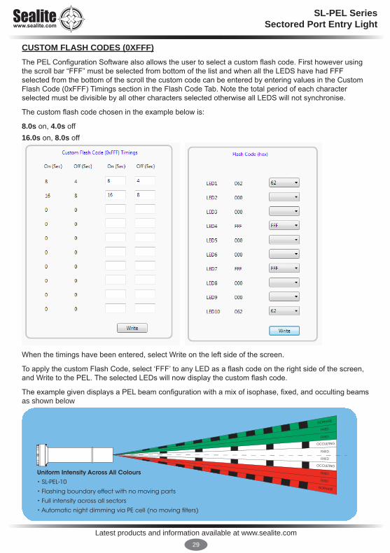
CUSTOM FLASH CODES (0XFFF)The PEL Configuration Software also allows the user to select a custom flash code. First however using the scroll bar “FFF” must be selected from bottom of the list and when all the LEDS have had FFF selected from the bottom of the scroll the custom code can be entered by entering values in the Custom Flash Code (0xFFF) Timings section in the Flash Code Tab. Note the total period of each character selected must be divisible by all other characters selected otherwise all LEDS will not synchronise.
The custom flash code chosen in the example below is:
8.0s on, 4.0s off16.0s on, 8.0s off
When the timings have been entered, select Write on the left side of the screen.
To apply the custom Flash Code, select ‘FFF’ to any LED as a flash code on the right side of the screen, and Write to the PEL. The selected LEDs will now display the custom flash code.
The example given displays a PEL beam configuration with a mix of isophase, fixed, and occulting beams as shown below
Uniform Intensity Across All Colours
• SL-PEL-10
• Flashing boundary effect with no moving parts
• Full intensity across all sectors
• Automatic night dimming via PE cell (no moving �lters)
FIXED
FIXED
ISOPHASE
OCCULTING
FIXED
FIXED
OCCULTING
FIXED
FIXED
ISOPHASE
Latest products and information available at www.sealite.com30
SL-PEL SeriesSectored Port Entry Light
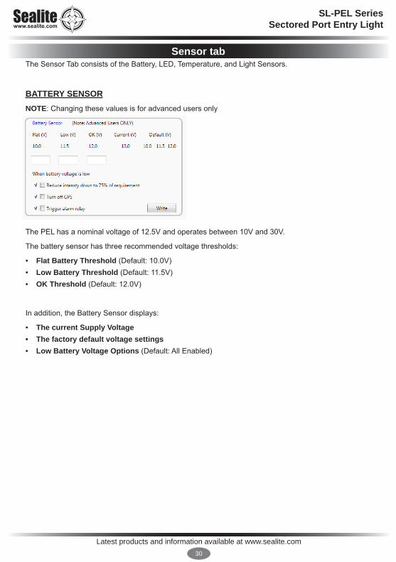
Sensor tabThe Sensor Tab consists of the Battery, LED, Temperature, and Light Sensors.
BATTERY SENSORNOTE: Changing these values is for advanced users only
The PEL has a nominal voltage of 12.5V and operates between 10V and 30V.
The battery sensor has three recommended voltage thresholds:
• Flat Battery Threshold (Default: 10.0V)• Low Battery Threshold (Default: 11.5V)• OK Threshold (Default: 12.0V)
In addition, the Battery Sensor displays:
• The current Supply Voltage• The factory default voltage settings• Low Battery Voltage Options (Default: All Enabled)
Latest products and information available at www.sealite.com31
SL-PEL SeriesSectored Port Entry Light
Changing Battery Thresholds
Identify voltages to be changed. Type the new voltages below the current voltage settings and click ‘Write.’ The voltage threshold settings will change.
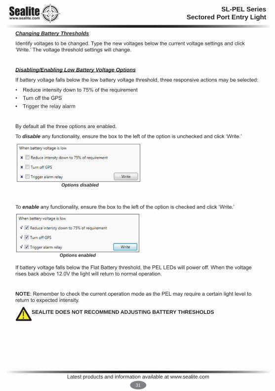
Disabling/Enabling Low Battery Voltage Options
If battery voltage falls below the low battery voltage threshold, three responsive actions may be selected:
• Reduce intensity down to 75% of the requirement• Turn off the GPS• Trigger the relay alarm
By default all the three options are enabled.
To disable any functionality, ensure the box to the left of the option is unchecked and click ‘Write.’
To enable any functionality, ensure the box to the left of the option is checked and click ‘Write.’
If battery voltage falls below the Flat Battery threshold, the PEL LEDs will power off. When the voltage rises back above 12.0V the light will return to normal operation.
NOTE: Remember to check the current operation mode as the PEL may require a certain light level to return to expected intensity.
SEALITE DOES NOT RECOMMEND ADJUSTING BATTERY THRESHOLDS
Options disabled
Options enabled
!

Latest products and information available at www.sealite.com32
SL-PEL SeriesSectored Port Entry Light
TEMPERATURE SENSORNOTE: Changing these values is for advanced users only
This sensor has been provided to offer service engineers confidence that the PEL is functioning properly regardless of outside conditions.
The Main Temperature Sensor monitors the main circuit board, has two temperature thresholds, and also displays the Current Temperature:
• High Temperature Threshold (Default: 70°C)• OK Temperature Threshold (Default: 65°C)• Current Temperature
• Default Temperature Settings
The LED Temperature Sensor monitors the LEDs, has two temperature thresholds, and also displays the Current Temperature:
• High Temperature Threshold (Default: 70°C)• OK Temperature Threshold (Default: 65°C)• Current Temperature
• Default Temperature Settings
Changing Temperature Thresholds
Identify temperatures to be changed. Type the new temperatures below the current temperature settings and click ‘Write.’ The temperature threshold settings will change.
SEALITE DOES NOT RECOMMEND ADJUSTING TEMPERATURE THRESHOLDS!

Latest products and information available at www.sealite.com33
SL-PEL SeriesSectored Port Entry Light
Disabling/Enabling Temperature Threshold Options
If temperature rises above the set temperature threshold, two responsive actions may be selected:
• Reduce intensity down to 75% of the requirement• Trigger the relay alarm
By default both options are enabled.
To disable any functionality, ensure the box to the left of the option is unchecked and click ‘Write.’
To enable any functionality, ensure the box to the left of the option is checked and click ‘Write.’
Options disabled
Options enabled

Latest products and information available at www.sealite.com34
SL-PEL SeriesSectored Port Entry Light
LED SENSOR (LED DIAGNOSTICS)
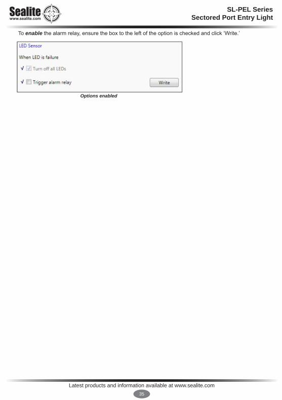
The voltage and current for each of the LEDs are monitored by the LED Sensor. If any LED fails, then all LEDs must be turned off. A faulty PEL is more dangerous than no PEL at all. When an LED failure is detected there is one* option that can be setup:
• Trigger alarm relay (Default: On)
*Turning off all LEDs upon failure is permanently enabled.
The PEL will re-run the LED diagnostics when it detects a day to night transition, or a night to day transition. This will mean that if the LED failure is only temporary then the PEL will resume normal operations the next day/night.
NOTE: A custom configuration may not have all LEDs populated. If a factory reset is performed, LEDs not being used will need to be switched to Zero intensity. This is discussed further in the Advanced Tab section.
Disabling/Enabling Alarm Options
To disable the alarm relay, ensure the box to the left of the option is unchecked and click ‘Write.’
Options disabled
Latest products and information available at www.sealite.com35
SL-PEL SeriesSectored Port Entry Light
To enable the alarm relay, ensure the box to the left of the option is checked and click ‘Write.’
Options enabled
Latest products and information available at www.sealite.com36
SL-PEL SeriesSectored Port Entry Light
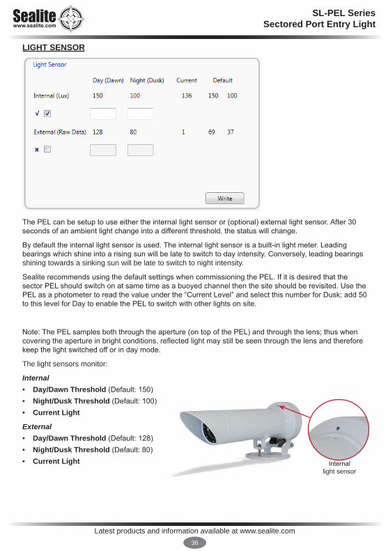
LIGHT SENSOR
The PEL can be setup to use either the internal light sensor or (optional) external light sensor. After 30 seconds of an ambient light change into a different threshold, the status will change.
By default the internal light sensor is used. The internal light sensor is a built-in light meter. Leading bearings which shine into a rising sun will be late to switch to day intensity. Conversely, leading bearings shining towards a sinking sun will be late to switch to night intensity.
Sealite recommends using the default settings when commissioning the PEL. If it is desired that the sector PEL should switch on at same time as a buoyed channel then the site should be revisited. Use the PEL as a photometer to read the value under the “Current Level” and select this number for Dusk; add 50 to this level for Day to enable the PEL to switch with other lights on site.
Note: The PEL samples both through the aperture (on top of the PEL) and through the lens; thus when covering the aperture in bright conditions, reflected light may still be seen through the lens and therefore keep the light switched off or in day mode.
The light sensors monitor:
Internal • Day/Dawn Threshold (Default: 150)• Night/Dusk Threshold (Default: 100)• Current Light
External • Day/Dawn Threshold (Default: 128)• Night/Dusk Threshold (Default: 80)• Current Light Internal
light sensor

Latest products and information available at www.sealite.com37
SL-PEL SeriesSectored Port Entry Light
Managing Light Sensor Thresholds
Both light meters may not be enabled at the same time.
To disable the external sensor and enable internal sensor, select the box to the left of the Internal Sensor and click ‘Write.’ The Software will automatically unselect the external sensor.
To disable the internal sensor and enable external sensor, select the box to the left of the External Sensor and click ‘Write.’ The Software will automatically unselect the internal sensor.
Changing Light Thresholds
Identify light thresholds to be changed. Type the new thresholds below the current Lux settings and click ‘Write.’ The Lux threshold settings will change. Note: If the light sensor is not enabled, changes to the settings may not be made.
Internal enabled
External enabled

Latest products and information available at www.sealite.com38
SL-PEL SeriesSectored Port Entry Light
Advanced tabThe Advanced Tab consists of Lantern Information and Lantern Setup and is a summary of Operation Mode, Intensities and Flash Settings.
LANTERN INFORMATION
This area displays:
• LED Colour Configurations• Night-time and Daytime Intensity Settings (Percentage)• Flash Code Settings (Hex)• Sync Offset (sec)• Operation Mode

Latest products and information available at www.sealite.com39
SL-PEL SeriesSectored Port Entry Light
LANTERN SETUP
Latest products and information available at www.sealite.com40
SL-PEL SeriesSectored Port Entry Light
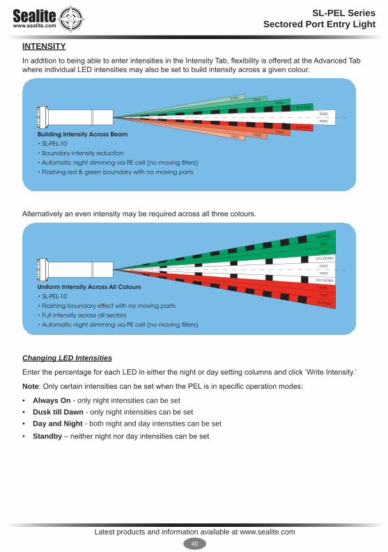
INTENSITYIn addition to being able to enter intensities in the Intensity Tab, flexibility is offered at the Advanced Tab where individual LED intensities may also be set to build intensity across a given colour.
Alternatively an even intensity may be required across all three colours.
Changing LED Intensities
Enter the percentage for each LED in either the night or day setting columns and click ‘Write Intensity.’
Note: Only certain intensities can be set when the PEL is in specific operation modes:
• Always On - only night intensities can be set• Dusk till Dawn - only night intensities can be set• Day and Night - both night and day intensities can be set
• Standby – neither night nor day intensities can be set
Uniform Intensity Across All Colours
• SL-PEL-10
• Flashing boundary effect with no moving parts
• Full intensity across all sectors
• Automatic night dimming via PE cell (no moving �lters)
FIXED
FIXED
ISOPHASE
OCCULTING
FIXED
FIXED
OCCULTING
FIXED
FIXED
ISOPHASE
Building Intensity Across Beam
• SL-PEL-10
• Boundary intensity reduction
• Automatic night dimming via PE cell (no moving �lters)
• Flashing red & green boundary with no moving parts
FIXEDFIXEDFIXED
ISOPHASE
FIXED
FIXED
ISOPHASEFIXED
FIXEDFIXED
Latest products and information available at www.sealite.com41
SL-PEL SeriesSectored Port Entry Light
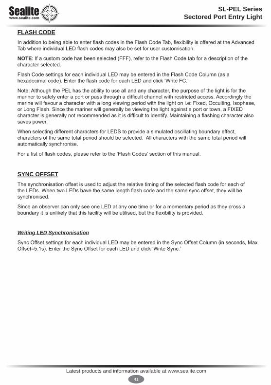
FLASH CODEIn addition to being able to enter flash codes in the Flash Code Tab, flexibility is offered at the Advanced Tab where individual LED flash codes may also be set for user customisation.
NOTE: If a custom code has been selected (FFF), refer to the Flash Code tab for a description of the character selected.
Flash Code settings for each individual LED may be entered in the Flash Code Column (as a hexadecimal code). Enter the flash code for each LED and click ‘Write FC.’
Note: Although the PEL has the ability to use all and any character, the purpose of the light is for the mariner to safely enter a port or pass through a difficult channel with restricted access. Accordingly the marine will favour a character with a long viewing period with the light on i.e: Fixed, Occulting, Isophase, or Long Flash. Since the mariner will generally be viewing the light against a port or town, a FIXED character is generally not recommended as it is difficult to identify. Maintaining a flashing character also saves power.
When selecting different characters for LEDS to provide a simulated oscillating boundary effect, characters of the same total period should be selected. All characters with the same total period will automatically synchronise.
For a list of flash codes, please refer to the ‘Flash Codes’ section of this manual.
SYNC OFFSETThe synchronisation offset is used to adjust the relative timing of the selected flash code for each of the LEDs. When two LEDs have the same length flash code and the same sync offset, they will be synchronised.
Since an observer can only see one LED at any one time or for a momentary period as they cross a boundary it is unlikely that this facility will be utilised, but the flexibility is provided.
Writing LED Synchronisation
Sync Offset settings for each individual LED may be entered in the Sync Offset Column (in seconds, Max Offset=5.1s). Enter the Sync Offset for each LED and click ‘Write Sync.’
Latest products and information available at www.sealite.com42
SL-PEL SeriesSectored Port Entry Light
AIS Report tab
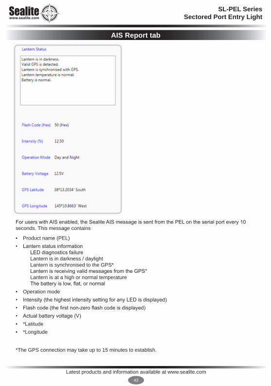
For users with AIS enabled, the Sealite AIS message is sent from the PEL on the serial port every 10 seconds. This message contains
• Product name (PEL)• Lantern status information
LED diagnostics failure Lantern is in darkness / daylight Lantern is synchronised to the GPS* Lantern is receiving valid messages from the GPS* Lantern is at a high or normal temperature The battery is low, flat, or normal
• Operation mode• Intensity (the highest intensity setting for any LED is displayed)• Flash code (the first non-zero flash code is displayed)• Actual battery voltage (V)• *Latitude • *Longitude
*The GPS connection may take up to 15 minutes to establish.
Latest products and information available at www.sealite.com43
SL-PEL SeriesSectored Port Entry Light
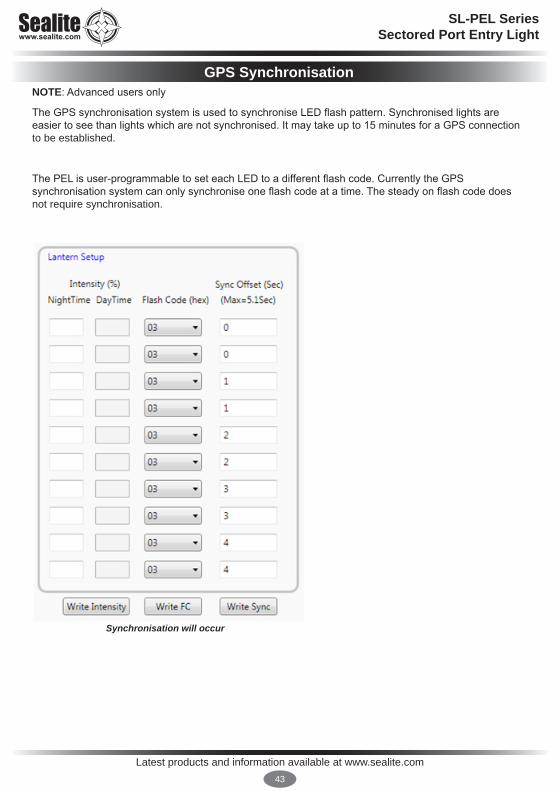
GPS SynchronisationNOTE: Advanced users only
The GPS synchronisation system is used to synchronise LED flash pattern. Synchronised lights are easier to see than lights which are not synchronised. It may take up to 15 minutes for a GPS connection to be established.
The PEL is user-programmable to set each LED to a different flash code. Currently the GPS synchronisation system can only synchronise one flash code at a time. The steady on flash code does not require synchronisation.
Synchronisation will occur

Latest products and information available at www.sealite.com44
SL-PEL SeriesSectored Port Entry Light
Under harsh environmental conditions the GPS data may not be available. If a loss of GPS data is encountered the lantern should keep its GPS active until the problem is rectified.
Synchronisation will not occur

Latest products and information available at www.sealite.com45
SL-PEL SeriesSectored Port Entry Light
Range of SL-PEL-10 @ T=0.74 at night
See Reference Guide ‘Daytime Range of Signal Lights’
• Synchronised LEDs are programmable in both intensity and character
• Length of beam indicates intensity
• Illustration shows SL-PEL-10 with 10 x 1º sectors
• The SL-PEL-05 variant produces 10 x 0.5º sectors
Diagram 1: Building Intensity Across Beam
• SL-PEL-10
• Boundary intensity reduction
• Automatic night dimming via PE cell (no moving �lters)
• Flashing red & green boundary with no moving parts
Diagram 3: Composite Station
• 2 x SL-PEL-10
• Synchronised horizontally to broaden beam and retain intensity
• Synchronised vertically to double intensity
• Automatic night dimming via PE cell (no moving �lters)
Diagram 2: Uniform Intensity Across All Colours
• SL-PEL-10
• Flashing boundary effect with no moving parts
• Full intensity across all sectors
• Automatic night dimming via PE cell (no moving �lters)
Examples of PEL Beam Con�gurations
FIXEDFIXEDFIXED
ISOPHASE
FIXED
FIXED
ISOPHASEFIXED
FIXEDFIXED
FIXED
FIXED
ISOPHASE
OCCULTING
FIXED
FIXED
ISOPHASE
FIXED
FIXED
ISOPHASE
FIXED
FIXEDISOPHASE
FIXED
FIXED
OCCULTING
FIXED
FIXED
FIXED
FIXED
FIXED
FIXED
OCCULTING
FIXED
FIXED
FIXED
FIXED
FIXED
FIXEDISOPHASE
Examples of PEL Beam Configurations

Latest products and information available at www.sealite.com46
SL-PEL SeriesSectored Port Entry Light
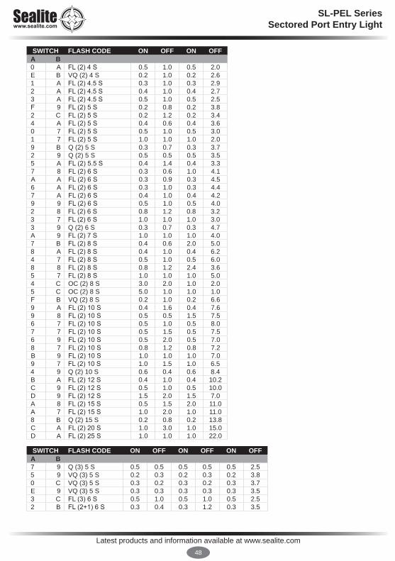
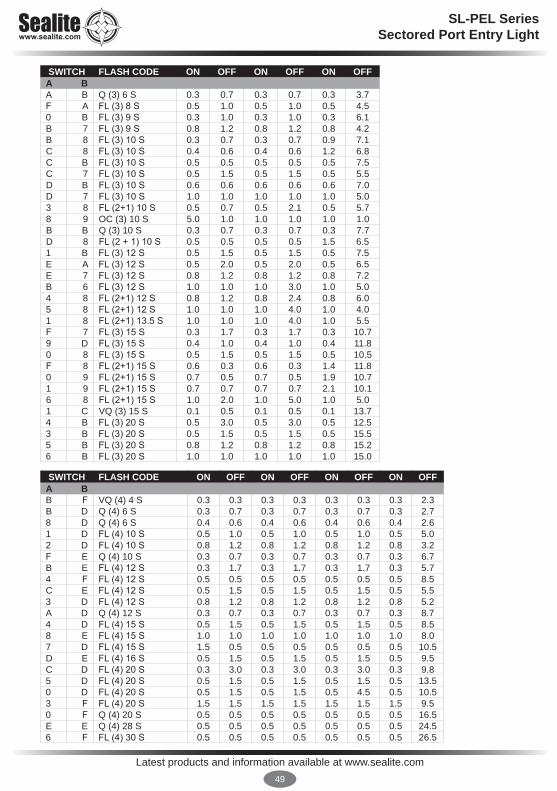
Flash CodesThe Sealite Port Entry Light may be set to any of 256 IALA recommended flash settings which are user-adjustable onsite without the need for external devices.
SEALITE® code reference is listed by number of flashes
For the latest version of this document visit www.sealite.com, or email [email protected]
SymbolsFL Flash followed by number Eg. FL 1 S, one flash every secondF FixedQ Quick flashVQ Very quick flashOC Occulting; greater period on than off ISO Isophase; equal period on and offLFL Long flash longMO Morse code ( ) contains letter
For example, VQ (6) + LFL 10 S means 6 very quick flashes followed by a long flash, during a 10-second interval.The amount of power your light draws through the night depends on the duty cycle, i.e. the amount of time on as a proportion to the timing cycle. For example, 0.5 seconds on and 4.5 seconds off equals a 10% duty cycle. It is best to operate at the lowest duty cycle appropriate to the actual needs of the application.
Recommended Rhythm for Flashing Light - IALA Regions A and B
MARK DESCRIPTION RHYTHMPort Hand & Starboard Marks: Any, other than Composite Group Flashing (2+1)
Preferred Channel Starboard: Composite Group Flashing (2+1)
Preferred Channel Port: Composite Group Flashing (2+1)
North Cardinal Mark: Very quick or quick
East Cardinal Mark: Very quick (3) every 5 seconds or quick (3) every 10 seconds
South Cardinal Mark: Very quick (6) + long flash every 10 seconds or quick (6) + long flash every 15 seconds
West Cardinal Mark: Very quick (9) every 10 seconds or quick (9) every 15 seconds
Isolated Danger Mark: Group flashing (2)
Safe Water Mark: Isophase, occulting, one long flash every 10 seconds or Morse Code “A”
Special Marks: Any, other than those described for Cardinal, Isolated Danger or Safe Water Marks

Latest products and information available at www.sealite.com47
SWITCH FLASH CODE ON OFFA B0 0 F (Steady light)D 3 VQ 0.5 S 0.2 0.3E 3 VQ 0.6 S 0.2 0.4F 3 VQ 0.6 S 0.3 0.37 3 Q 1 S 0.2 0.88 3 Q 1 S 0.3 0.79 3 Q 1 S 0.4 0.6A 3 Q 1 S 0.5 0.58 4 Q 1 S 0.8 0.2B 3 Q 1.2 S 0.3 0.99 4 Q 1.2 S 0.5 0.7C 3 Q 1.2 S 0.6 0.6F 4 FL 1.5 S 0.2 1.31 0 FL 1.5 S 0.3 1.20 5 FL 1.5 S 0.4 1.10 4 FL 1.5 S 0.5 1.02 0 FL 2 S 0.2 1.83 0 FL 2 S 0.3 1.74 0 FL 2 S 0.4 1.65 0 FL 2 S 0.5 1.56 0 FL 2 S 0.7 1.37 0 FL 2 S 0.8 1.21 2 ISO 2 S 1.0 1.08 0 FL 2.5 S 0.3 2.29 0 FL 2.5 S 0.5 2.0D 6 FL 2.5 S 1.0 1.51 5 FL 3 S 0.2 2.8A 0 FL 3 S 0.3 2.72 5 FL 3 S 0.4 2.6B 0 FL 3 S 0.5 2.53 5 FL 3 S 0.6 2.4C 0 FL 3 S 0.7 2.3D 0 FL 3 S 1.0 2.02 2 ISO 3 S 1.5 1.55 4 OC 3 S 2.0 1.0E 2 OC 3 S 2.5 0.54 6 OC 3.5 S 2.5 1.04 5 FL 4 S 0.2 3.85 5 FL 4 S 0.3 3.7E 0 FL 4 S 0.4 3.6F 0 FL 4 S 0.5 3.56 5 FL 4 S 0.6 3.40 1 FL 4 S 0.8 3.21 1 FL 4 S 1.0 3.02 1 FL 4 S 1.5 2.53 2 ISO 4 S 2.0 2.03 6 OC 4 S 2.5 1.5F 2 OC 4 S 3.0 1.03 1 FL 4.3 S 1.3 3.08 5 FL 5 S 0.2 4.84 1 FL 5 S 0.3 4.75 1 FL 5 S 0.5 4.59 5 FL 5 S 0.9 4.16 1 FL 5 S 1.0 4.0
SWITCH FLASH CODE ON OFFA B7 1 FL 5 S 1.5 3.54 2 ISO 5 S 2.5 2.58 2 LFL 5 S 2.0 3.00 3 OC 5 S 3.0 2.01 3 OC 5 S 4.0 1.02 3 OC 5 S 4.5 0.5C 6 FL 6 S 0.2 5.8B 5 FL 6 S 0.3 5.7C 5 FL 6 S 0.4 5.68 1 FL 6 S 0.5 5.59 1 FL 6 S 0.6 5.4A 1 FL 6 S 1.0 5.07 5 FL 6 S 1.2 4.8B 1 FL 6 S 1.5 4.55 2 ISO 6 S 3.0 3.09 2 LFL 6 S 2.0 4.06 4 OC 6 S 4.0 2.03 3 OC 6 S 4.5 1.54 3 OC 6 S 5.0 1.0A 4 FL 7 S 1.0 6.09 6 FL 7 S 2.0 5.05 6 OC 7 S 4.5 2.5D 5 FL 7.5 S 0.5 7.0C 1 FL 7.5 S 0.8 6.7E 5 FL 8 S 0.5 7.5B 4 FL 8 S 1.0 7.06 2 ISO 8 S 4.0 4.0A 2 LFL 8 S 2.0 6.06 6 OC 8 S 5.0 3.0B 2 LFL 8 S 3.0 5.0F 5 FL 9 S 0.9 8.1C 4 FL 9 S 1.0 8.07 6 OC 9 S 6.0 3.00 6 FL 10 S 0.2 9.81 6 FL 10 S 0.3 9.7D 1 FL 10 S 0.5 9.52 6 FL 10 S 0.8 9.2E 1 FL 10 S 1.0 9.01 4 FL 10 S 1.5 8.5C 2 LFL 10 S 2.0 8.0D 2 LFL 10 S 3.0 7.07 2 ISO 10 S 5.0 5.02 4 LFL 10 S 4.0 6.08 6 OC 10 S 6.0 4.05 3 OC 10 S 7.0 3.06 3 OC 10 S 7.5 2.5F 1 FL 12 S 1.2 10.8D 4 FL 12 S 2.5 9.53 4 LFL 12 S 2.0 10.00 2 FL 15 S 1.0 14.04 4 LFL 15 S 4.0 11.07 4 OC 15 S 10 5.0A 6 LFL 20 S 2.0 18.0E 4 FL 26 S 1.0 25.0
Latest products and information available at www.sealite.com48
SL-PEL SeriesSectored Port Entry Light
SWITCH FLASH CODE ON OFF ON OFFA B0 A FL (2) 4 S 0.5 1.0 0.5 2.0E B VQ (2) 4 S 0.2 1.0 0.2 2.61 A FL (2) 4.5 S 0.3 1.0 0.3 2.92 A FL (2) 4.5 S 0.4 1.0 0.4 2.73 A FL (2) 4.5 S 0.5 1.0 0.5 2.5F 9 FL (2) 5 S 0.2 0.8 0.2 3.82 C FL (2) 5 S 0.2 1.2 0.2 3.44 A FL (2) 5 S 0.4 0.6 0.4 3.60 7 FL (2) 5 S 0.5 1.0 0.5 3.01 7 FL (2) 5 S 1.0 1.0 1.0 2.09 B Q (2) 5 S 0.3 0.7 0.3 3.72 9 Q (2) 5 S 0.5 0.5 0.5 3.55 A FL (2) 5.5 S 0.4 1.4 0.4 3.37 8 FL (2) 6 S 0.3 0.6 1.0 4.1A A FL (2) 6 S 0.3 0.9 0.3 4.56 A FL (2) 6 S 0.3 1.0 0.3 4.47 A FL (2) 6 S 0.4 1.0 0.4 4.29 9 FL (2) 6 S 0.5 1.0 0.5 4.02 8 FL (2) 6 S 0.8 1.2 0.8 3.23 7 FL (2) 6 S 1.0 1.0 1.0 3.03 9 Q (2) 6 S 0.3 0.7 0.3 4.7A 9 FL (2) 7 S 1.0 1.0 1.0 4.07 B FL (2) 8 S 0.4 0.6 2.0 5.08 A FL (2) 8 S 0.4 1.0 0.4 6.24 7 FL (2) 8 S 0.5 1.0 0.5 6.08 8 FL (2) 8 S 0.8 1.2 2.4 3.65 7 FL (2) 8 S 1.0 1.0 1.0 5.04 C OC (2) 8 S 3.0 2.0 1.0 2.05 C OC (2) 8 S 5.0 1.0 1.0 1.0F B VQ (2) 8 S 0.2 1.0 0.2 6.69 A FL (2) 10 S 0.4 1.6 0.4 7.69 8 FL (2) 10 S 0.5 0.5 1.5 7.56 7 FL (2) 10 S 0.5 1.0 0.5 8.07 7 FL (2) 10 S 0.5 1.5 0.5 7.56 9 FL (2) 10 S 0.5 2.0 0.5 7.08 7 FL (2) 10 S 0.8 1.2 0.8 7.2B 9 FL (2) 10 S 1.0 1.0 1.0 7.09 7 FL (2) 10 S 1.0 1.5 1.0 6.54 9 Q (2) 10 S 0.6 0.4 0.6 8.4B A FL (2) 12 S 0.4 1.0 0.4 10.2C 9 FL (2) 12 S 0.5 1.0 0.5 10.0D 9 FL (2) 12 S 1.5 2.0 1.5 7.0A 8 FL (2) 15 S 0.5 1.5 2.0 11.0A 7 FL (2) 15 S 1.0 2.0 1.0 11.08 B Q (2) 15 S 0.2 0.8 0.2 13.8C A FL (2) 20 S 1.0 3.0 1.0 15.0D A FL (2) 25 S 1.0 1.0 1.0 22.0
SWITCH FLASH CODE ON OFF ON OFF ON OFFA B7 9 Q (3) 5 S 0.5 0.5 0.5 0.5 0.5 2.55 9 VQ (3) 5 S 0.2 0.3 0.2 0.3 0.2 3.80 C VQ (3) 5 S 0.3 0.2 0.3 0.2 0.3 3.7E 9 VQ (3) 5 S 0.3 0.3 0.3 0.3 0.3 3.53 C FL (3) 6 S 0.5 1.0 0.5 1.0 0.5 2.52 B FL (2+1) 6 S 0.3 0.4 0.3 1.2 0.3 3.5
Latest products and information available at www.sealite.com49
SL-PEL SeriesSectored Port Entry Light
SWITCH FLASH CODE ON OFF ON OFF ON OFFA BA B Q (3) 6 S 0.3 0.7 0.3 0.7 0.3 3.7F A FL (3) 8 S 0.5 1.0 0.5 1.0 0.5 4.50 B FL (3) 9 S 0.3 1.0 0.3 1.0 0.3 6.1B 7 FL (3) 9 S 0.8 1.2 0.8 1.2 0.8 4.2B 8 FL (3) 10 S 0.3 0.7 0.3 0.7 0.9 7.1C 8 FL (3) 10 S 0.4 0.6 0.4 0.6 1.2 6.8C B FL (3) 10 S 0.5 0.5 0.5 0.5 0.5 7.5C 7 FL (3) 10 S 0.5 1.5 0.5 1.5 0.5 5.5D B FL (3) 10 S 0.6 0.6 0.6 0.6 0.6 7.0D 7 FL (3) 10 S 1.0 1.0 1.0 1.0 1.0 5.03 8 FL (2+1) 10 S 0.5 0.7 0.5 2.1 0.5 5.78 9 OC (3) 10 S 5.0 1.0 1.0 1.0 1.0 1.0B B Q (3) 10 S 0.3 0.7 0.3 0.7 0.3 7.7D 8 FL (2 + 1) 10 S 0.5 0.5 0.5 0.5 1.5 6.51 B FL (3) 12 S 0.5 1.5 0.5 1.5 0.5 7.5E A FL (3) 12 S 0.5 2.0 0.5 2.0 0.5 6.5E 7 FL (3) 12 S 0.8 1.2 0.8 1.2 0.8 7.2B 6 FL (3) 12 S 1.0 1.0 1.0 3.0 1.0 5.04 8 FL (2+1) 12 S 0.8 1.2 0.8 2.4 0.8 6.05 8 FL (2+1) 12 S 1.0 1.0 1.0 4.0 1.0 4.01 8 FL (2+1) 13.5 S 1.0 1.0 1.0 4.0 1.0 5.5F 7 FL (3) 15 S 0.3 1.7 0.3 1.7 0.3 10.79 D FL (3) 15 S 0.4 1.0 0.4 1.0 0.4 11.80 8 FL (3) 15 S 0.5 1.5 0.5 1.5 0.5 10.5F 8 FL (2+1) 15 S 0.6 0.3 0.6 0.3 1.4 11.80 9 FL (2+1) 15 S 0.7 0.5 0.7 0.5 1.9 10.71 9 FL (2+1) 15 S 0.7 0.7 0.7 0.7 2.1 10.16 8 FL (2+1) 15 S 1.0 2.0 1.0 5.0 1.0 5.01 C VQ (3) 15 S 0.1 0.5 0.1 0.5 0.1 13.74 B FL (3) 20 S 0.5 3.0 0.5 3.0 0.5 12.53 B FL (3) 20 S 0.5 1.5 0.5 1.5 0.5 15.55 B FL (3) 20 S 0.8 1.2 0.8 1.2 0.8 15.26 B FL (3) 20 S 1.0 1.0 1.0 1.0 1.0 15.0
SWITCH FLASH CODE ON OFF ON OFF ON OFF ON OFFA BB F VQ (4) 4 S 0.3 0.3 0.3 0.3 0.3 0.3 0.3 2.3B D Q (4) 6 S 0.3 0.7 0.3 0.7 0.3 0.7 0.3 2.78 D Q (4) 6 S 0.4 0.6 0.4 0.6 0.4 0.6 0.4 2.61 D FL (4) 10 S 0.5 1.0 0.5 1.0 0.5 1.0 0.5 5.02 D FL (4) 10 S 0.8 1.2 0.8 1.2 0.8 1.2 0.8 3.2F E Q (4) 10 S 0.3 0.7 0.3 0.7 0.3 0.7 0.3 6.7B E FL (4) 12 S 0.3 1.7 0.3 1.7 0.3 1.7 0.3 5.74 F FL (4) 12 S 0.5 0.5 0.5 0.5 0.5 0.5 0.5 8.5C E FL (4) 12 S 0.5 1.5 0.5 1.5 0.5 1.5 0.5 5.53 D FL (4) 12 S 0.8 1.2 0.8 1.2 0.8 1.2 0.8 5.2A D Q (4) 12 S 0.3 0.7 0.3 0.7 0.3 0.7 0.3 8.74 D FL (4) 15 S 0.5 1.5 0.5 1.5 0.5 1.5 0.5 8.58 E FL (4) 15 S 1.0 1.0 1.0 1.0 1.0 1.0 1.0 8.07 D FL (4) 15 S 1.5 0.5 0.5 0.5 0.5 0.5 0.5 10.5D E FL (4) 16 S 0.5 1.5 0.5 1.5 0.5 1.5 0.5 9.5C D FL (4) 20 S 0.3 3.0 0.3 3.0 0.3 3.0 0.3 9.85 D FL (4) 20 S 0.5 1.5 0.5 1.5 0.5 1.5 0.5 13.50 D FL (4) 20 S 0.5 1.5 0.5 1.5 0.5 4.5 0.5 10.53 F FL (4) 20 S 1.5 1.5 1.5 1.5 1.5 1.5 1.5 9.50 F Q (4) 20 S 0.5 0.5 0.5 0.5 0.5 0.5 0.5 16.5E E Q (4) 28 S 0.5 0.5 0.5 0.5 0.5 0.5 0.5 24.56 F FL (4) 30 S 0.5 0.5 0.5 0.5 0.5 0.5 0.5 26.5

Latest products and information available at www.sealite.com50
SL-PEL SeriesSectored Port Entry Light
SWITCH FLASH CODE ON OFF ON OFF ON OFF ON OFF ON OFF ON OFF ON OFF ON OFF ON OFFA B4 E VQ (9) 10 S 0.2 0.3 0.2 0.3 0.2 0.3 0.2 0.3 0.2 0.3 0.2 0.3 0.2 0.3 0.2 0.3 0.2 5.85 E VQ (9) 10 S 0.3 0.3 0.3 0.3 0.3 0.3 0.3 0.3 0.3 0.3 0.3 0.3 0.3 0.3 0.3 0.3 0.3 4.91 F Q (9) 15 S 0.2 0.8 0.2 0.8 0.2 0.8 0.2 0.8 0.2 0.8 0.2 0.8 0.2 0.8 0.2 0.8 0.2 6.80 E Q (9) 15 S 0.3 0.7 0.3 0.7 0.3 0.7 0.3 0.7 0.3 0.7 0.3 0.7 0.3 0.7 0.3 0.7 0.3 6.71 E Q (9) 15 S 0.6 0.6 0.6 0.6 0.6 0.6 0.6 0.6 0.6 0.6 0.6 0.6 0.6 0.6 0.6 0.6 0.6 4.8
SWITCH FLASH CODE ON OFF ON OFF ON OFF ON OFFA BMORSE CODE ( ) INDICATES LETTER7 8 MO (A) 6 S 0.3 0.6 1.0 4.17 B MO (A) 8 S 0.4 0.6 2.0 5.08 8 MO (A) 8 S 0.8 1.2 2.4 3.6B 8 MO (U) 10 S 0.3 0.7 0.3 0.7 0.9 7.1C 8 MO (U) 10 S 0.4 0.6 0.4 0.6 1.2 6.8D 8 MO (U) 10 S 0.5 0.5 0.5 0.5 1.5 6.59 8 MO (A) 10 S 0.5 0.5 1.5 7.58 9 MO (D) 10 S 5.0 1.0 1.0 1.0 1.0 1.0A 8 MO (A) 15 S 0.5 1.5 2.0 11.0F 8 MO (U) 15 S 0.6 0.3 0.6 0.3 1.4 11.80 9 MO (U) 15 S 0.7 0.5 0.7 0.5 1.9 10.71 9 MO (U) 15 S 0.7 0.7 0.7 0.7 2.1 10.17 D MO (B) 15 S 1.5 0.5 0.5 0.5 0.5 0.5 0.5 10.5
SWITCH FLASH CODE ON OFF ON OFF ON OFF ON OFF ON OFFA BD D Q (5) 7 S 0.3 0.7 0.3 0.7 0.3 0.7 0.3 0.7 0.3 2.7E D Q (5) 10 S 0.3 0.7 0.3 0.7 0.3 0.7 0.3 0.7 0.3 5.7E 8 FL (5) 12 S 0.5 1.5 0.5 1.5 0.5 1.5 0.5 1.5 0.5 3.55 F FL (5) 20 S 0.5 0.5 0.5 0.5 0.5 0.5 0.5 0.5 0.5 15.59 F FL (5) 20 S 0.8 1.2 0.8 1.2 0.8 1.2 0.8 1.2 0.8 11.29 E FL (5) 20 S 1.0 1.0 1.0 1.0 1.0 1.0 1.0 1.0 1.0 11.0
SWITCH FLASH CODE ON OFF ON OFF ON OFF ON OFF ON OFF ON OFFA BF D Q (6) 10 S 0.3 0.7 0.3 0.7 0.3 0.7 0.3 0.7 0.3 0.7 0.3 4.7A F FL (6) 15 S 0.3 0.7 0.3 0.7 0.3 0.7 0.3 0.7 0.3 0.7 0.3 9.77 F FL (6) 15 S 0.5 1.0 0.5 1.0 0.5 1.0 0.5 1.0 0.5 1.0 0.5 7.0
SWITCH FLASH CODE ON OFF ON OFF ON OFF ON OFF ON OFF ON OFF ON OFFA B6 E VQ (6) + LFL 10 S 0.2 0.3 0.2 0.3 0.2 0.3 0.2 0.3 0.2 0.3 0.2 0.3 2.0 5.07 E VQ (6) + LFL 10 S 0.3 0.3 0.3 0.3 0.3 0.3 0.3 0.3 0.3 0.3 0.3 0.3 2.0 4.42 F Q (6) + LFL 15 S 0.2 0.8 0.2 0.8 0.2 0.8 0.2 0.8 0.2 0.8 0.2 0.8 2.0 7.02 E Q (6) + LFL 15 S 0.3 0.7 0.3 0.7 0.3 0.7 0.3 0.7 0.3 0.7 0.3 0.7 2.0 7.03 E Q (6) + LFL 15 S 0.6 0.6 0.6 0.6 0.6 0.6 0.6 0.6 0.6 0.6 0.6 0.6 2.0 5.88 F VQ (6) + LFL 15 S 0.3 0.3 0.3 0.3 0.3 0.3 0.3 0.3 0.3 0.3 0.3 0.3 2.0 9.4
Latest products and information available at www.sealite.com51
SL-PEL SeriesSectored Port Entry Light
Optional GSM Cell-Phone Monitoring & ControlThe Sealite PEL is avialable with GSM monitoring facilities enabling users to access real-time diagnostics data and change lantern settings via cell-phone. The system can also be configured to send out alarm SMS text messages to designated cellular telephone numbers. Users can also have alarms and reports sent to designated email addresses.
Please contact Sealite for a copy of the GSM instruction manual.

Latest products and information available at www.sealite.com52
SL-PEL SeriesSectored Port Entry Light
Maintenance and ServicingThe PEL should be galvanically insulated from the bracket or tower it is mounted on by means of M10 A4 stainless bolts with insulated nylon washers to ensure the longevity of the PEL. Pin “D” core coloured green should be connected to a suitable GROUND on the structure. Although the lantern is protected against power surges everything should be done to safeguard the lantern from direct or near lightning strikes. The Sealite PEL is an LED light source and as a result does not require visits for re-lamping. If fitted with GSM or AIS monitoring the service technician will already have advance notice on the requirement for a visit.In the absence of any alarms it is recommended that the PEL be visited twice a year to suit site conditions. These conditions could be particularly where the light is exposed to season bird fouling or sand/dust deposits from harsh winds or it could be access is difficult during certain times of the year.Service personnel visiting the site should perform site visits with at least 5 litres of fresh, grit free soapy water and clean rags to remove any external build up of sand or bird guano. Before starting work Port Control should be contacted or the channel checked to ensure there is not a SHIP IN PASSAGE which this cleaning process will prevent from using.Special care should be taken when handling the Port Entry Light. Optics can be easily damaged from poor handling and incorrect cleaning methods. Be sure to consider the following guidelines:
- Never place hard or rough surfaces on PEL optics as the lens can be easily scratched and chipped.
- Optics should never be handled with bare fingers as oils from the skin may remove and damage coated and uncoated surfaces.
- Use only lint-free cloths or lens tissue when cleaning surface of the PEL lens
- Apply isopropyl alcohol (IPA) directly to your cloth – NEVER directly to the lens. Use slow, even, light pressure working from edge to edge across the PEL Lens allowing IPA to evaporate
- If storing the PEL ensure the optics and connectors are protected.
The same cleaning process should be taken into consideration with any accessories including: solar arrays, GSM or GPS units. All cable connections should be checked and tied down against wind and wave actions if applicable.Mounting fixings should be fixed for security and any weaknesses observed and noted.Pictures should be taken of the site condition before and after these actions.Once free of these deposits and dried with power still connected, using the USB lead and PC loaded with the programme the Unit can be read to check and record battery voltage. If the visit is other than regular maintenance the “event log” will be filled with up to 24 events. These events are recorded in the PEL RAM and are retained even if power has failed.The PEL cannot be read until it is powered up and COMs port selected as explained earlier in the manual. Events can be down loaded to a separate file for record purposes.
Latest products and information available at www.sealite.com53
SL-PEL SeriesSectored Port Entry Light
Trouble Shooting
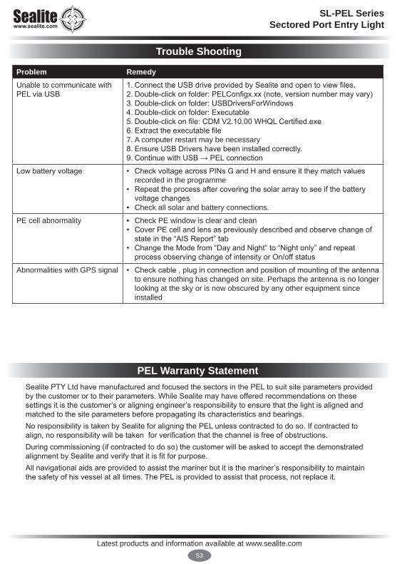
Problem RemedyUnable to communicate with PEL via USB
1. Connect the USB drive provided by Sealite and open to view files.2. Double-click on folder: PELConfigx.xx (note, version number may vary)3. Double-click on folder: USBDriversForWindows4. Double-click on folder: Executable5. Double-click on file: CDM V2.10.00 WHQL Certified.exe6. Extract the executable file7. A computer restart may be necessary8. Ensure USB Drivers have been installed correctly.9. Continue with USB → PEL connection
Low battery voltage • Check voltage across PINs G and H and ensure it they match values recorded in the programme
• Repeat the process after covering the solar array to see if the battery voltage changes
• Check all solar and battery connections.
PE cell abnormality • Check PE window is clear and clean• Cover PE cell and lens as previously described and observe change of
state in the “AIS Report” tab• Change the Mode from “Day and Night” to “Night only” and repeat
process observing change of intensity or On/off status
Abnormalities with GPS signal • Check cable , plug in connection and position of mounting of the antenna to ensure nothing has changed on site. Perhaps the antenna is no longer looking at the sky or is now obscured by any other equipment since installed
PEL Warranty StatementSealite PTY Ltd have manufactured and focused the sectors in the PEL to suit site parameters provided by the customer or to their parameters. While Sealite may have offered recommendations on these settings it is the customer’s or aligning engineer’s responsibility to ensure that the light is aligned and matched to the site parameters before propagating its characteristics and bearings. No responsibility is taken by Sealite for aligning the PEL unless contracted to do so. If contracted to align, no responsibility will be taken for verification that the channel is free of obstructions.During commissioning (if contracted to do so) the customer will be asked to accept the demonstrated alignment by Sealite and verify that it is fit for purpose. All navigational aids are provided to assist the mariner but it is the mariner’s responsibility to maintain the safety of his vessel at all times. The PEL is provided to assist that process, not replace it.

Latest products and information available at www.sealite.com54
SL-PEL SeriesSectored Port Entry Light
Activating the WarrantyUpon purchase, the Sealite Pty Ltd warranty must be activated for recognition of future claims. To do this you need to register on-line. Please complete the Online Registration Form at:www.sealite.comSealite Pty Ltd will repair or replace your LED light in the event of electronic failure for a period of up to three years from the date of purchase, as per the terms & conditions below.Sealite Pty Ltd will repair or replace any ancillary or accessory products in the event of failure for a period of up to one year from the date of purchase, as per the terms & conditions below.The unit(s) must be returned to Sealite freight prepaid.Warranty Terms 1. Sealite Pty Ltd warrants that any Sealite marine products fitted with telemetry equipment including but
not limited to AIS, GSM, GPS or RF (“Telemetry Products”) will be free from defective materials and workmanship under normal and intended use, subject to the conditions hereinafter set forth, for a period of twelve (12) months from the date of purchase by the original purchaser.
2. Sealite Pty Ltd warrants that any BargeSafe™ Series of LED barge light products (“BargeSafe™ Products”) will be free from defective materials and workmanship under normal and intended use, subject to the conditions hereinafter set forth, for a period of twelve (12) months from the date of purchase by the original purchaser.
3. Sealite Pty Ltd warrants that any LED area lighting products (“Area Lighting Products”) but not including sign lighting products will be free from defective materials and workmanship under normal and intended use, subject to the conditions hereinafter set forth, for a period of twelve (12) months from the date of purchase by the original purchaser.
4. Sealite Pty Ltd warrants that any ancillary products and accessories, not mentioned in other clauses in this section, will be free from defective materials and workmanship under normal and intended use, subject to the conditions hereinafter set forth, for a period of twelve (12) months from the date of purchase by the original purchaser.
5. Sealite Pty Ltd warrants that any LED sign lighting products (“Sign Lighting Products”) will be free from defective materials and workmanship under normal and intended use, subject to the conditions hereinafter set forth, for a period of three (3) years from the date of purchase by the original purchaser.
6. Sealite Pty Ltd warrants that any Sealite marine lighting products other than the Telemetry Products, BargeSafe™ Products, and Area Lighting Products (“Sealite Products”) will be free from defective materials and workmanship under normal and intended use, subject to the conditions hereinafter set forth, for a period of three (3) years from the date of purchase by the original purchaser.
7. Sealite Pty Ltd will repair or replace, at Sealite’s sole discretion, any Telemetry Products, BargeSafe™ Products, Area Lighting Products or Sealite Products found to be defective in material and workmanship in the relevant warranty period so long as the Warranty Conditions (set out below) are satisfied.
8. If any Telemetry Products, BargeSafe™ Products, Area Lighting Products or Sealite Products are fitted with a rechargeable battery, Sealite Pty Ltd warrants the battery will be free from defect for a period of one (1) year when used within original manufacturer’s specifications and instructions.
9. Buoy products are covered by a separate ‘Sealite Buoy Warranty’.
Warranty ConditionsThis Warranty is subject to the following conditions and limitations; 1. The warranty is applicable to lanterns manufactured from 1/1/2009.2. The warranty is void and inapplicable if:
a. the product has been used or handled other than in accordance with the instructions in the owner’s manual and any other information or instructions provided to the customer by Sealite;
b. the product has been deliberately abused, or misused, damaged by accident or neglect or in being transported; or
c. the defect is due to the product being repaired or tampered with by anyone other than Sealite or
Sealite LED Light Warranty V2.2
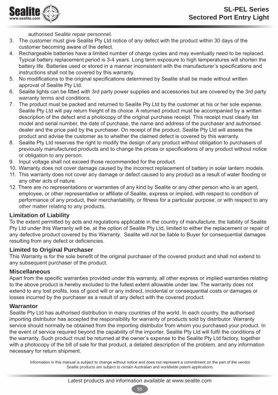
Latest products and information available at www.sealite.com55
SL-PEL SeriesSectored Port Entry Light
Information in this manual is subject to change without notice and does not represent a commitment on the part of the vendor. Sealite products are subject to certain Australian and worldwide patent applications.
authorised Sealite repair personnel. 3. The customer must give Sealite Pty Ltd notice of any defect with the product within 30 days of the
customer becoming aware of the defect. 4. Rechargeable batteries have a limited number of charge cycles and may eventually need to be replaced.
Typical battery replacement period is 3-4 years. Long term exposure to high temperatures will shorten the battery life. Batteries used or stored in a manner inconsistent with the manufacturer’s specifications and instructions shall not be covered by this warranty.
5. No modifications to the original specifications determined by Sealite shall be made without written approval of Sealite Pty Ltd.
6. Sealite lights can be fitted with 3rd party power supplies and accessories but are covered by the 3rd party warranty terms and conditions.
7. The product must be packed and returned to Sealite Pty Ltd by the customer at his or her sole expense. Sealite Pty Ltd will pay return freight of its choice. A returned product must be accompanied by a written description of the defect and a photocopy of the original purchase receipt. This receipt must clearly list model and serial number, the date of purchase, the name and address of the purchaser and authorised dealer and the price paid by the purchaser. On receipt of the product, Sealite Pty Ltd will assess the product and advise the customer as to whether the claimed defect is covered by this warranty.
8. Sealite Pty Ltd reserves the right to modify the design of any product without obligation to purchasers of previously manufactured products and to change the prices or specifications of any product without notice or obligation to any person.
9. Input voltage shall not exceed those recommended for the product.10. Warranty does not cover damage caused by the incorrect replacement of battery in solar lantern models.11. This warranty does not cover any damage or defect caused to any product as a result of water flooding or
any other acts of nature.12. There are no representations or warranties of any kind by Sealite or any other person who is an agent,
employee, or other representative or affiliate of Sealite, express or implied, with respect to condition of performance of any product, their merchantability, or fitness for a particular purpose, or with respect to any other matter relating to any products.
Limitation of LiabilityTo the extent permitted by acts and regulations applicable in the country of manufacture, the liability of Sealite Pty Ltd under this Warranty will be, at the option of Sealite Pty Ltd, limited to either the replacement or repair of any defective product covered by this Warranty. Sealite will not be liable to Buyer for consequential damages resulting from any defect or deficiencies.
Limited to Original Purchaser This Warranty is for the sole benefit of the original purchaser of the covered product and shall not extend to any subsequent purchaser of the product.
MiscellaneousApart from the specific warranties provided under this warranty, all other express or implied warranties relating to the above product is hereby excluded to the fullest extent allowable under law. The warranty does not extend to any lost profits, loss of good will or any indirect, incidental or consequential costs or damages or losses incurred by the purchaser as a result of any defect with the covered product.
WarrantorSealite Pty Ltd has authorised distribution in many countries of the world. In each country, the authorised importing distributor has accepted the responsibility for warranty of products sold by distributor. Warranty service should normally be obtained from the importing distributor from whom you purchased your product. In the event of service required beyond the capability of the importer, Sealite Pty Ltd will fulfil the conditions of the warranty. Such product must be returned at the owner’s expense to the Sealite Pty Ltd factory, together with a photocopy of the bill of sale for that product, a detailed description of the problem, and any information necessary for return shipment.
SL-PEL SeriesSectored Port Entry Light
Other Sealite Products Available
Marine Lanterns (1–19NM)
Bridge & Barge Lights
Area Lighting
Monitoring & Control Systems
Marine Buoys(up to 3mt in diameter)
Mooring Systems & Accessories
Sealite United Kingdom LtdUKt: +44 (0) 1502 588026
Sealite Asia Pte LtdSingapore
Sealite USA LLCUSA
t: +65 6829 2243 t: +1 (603) 737 1311
Sealite Pty LtdAustraliat: +61 (0)3 5977 6128
We believe technology improves navigation™ [email protected]