Installation, Service & Spectrum Operation Manual · Installation, Service & Operation Manual SoftH...
17
Table of Contents 1. Description & Equipment Adjustments p.2 2. Components, Features & Functions p.3 3. Valve User Interface p.4 4. Installation Instructions p.5 5. Valve Initial Set-up p.7 6. Manual Regeneration p.10 7. Water Hardness Adjustment p.10 8. End User Instructions p.11 9. Troubleshooting p.12 10. Cautions p.14 11. System Parts p.15 12. Technical Information p.17 Installation, Service & Operation Manual SoftH 2 O Chrono Spectrum TM Water Softener
Transcript of Installation, Service & Spectrum Operation Manual · Installation, Service & Operation Manual SoftH...

Table of Contents
1. Description & Equipment Adjustments p.22. Components, Features & Functions p.33. Valve User Interface p.44. Installation Instructions p.55. Valve Initial Set-up p.76. Manual Regeneration p.107. Water Hardness Adjustment p.108. End User Instructions p.119. Troubleshooting p.1210. Cautions p.1411. System Parts p.1512. Technical Information p.17
Installation, Service &Operation ManualSoftH2O Chrono
SpectrumTM
Water Softener

SpectrumTM
2
Regeneration Mode
Regeneration Type
Electrical Supply
Installation Number Nominal Capacity m3 °tH
Valve Serial Number Inlet Water Hardness °tH
Tank Size 10 x 17 Treated Water Volume litres
Resin Type Food Grade Anion Outlet Water Hardness °tH
Resin Volume 13 litres Salt Quantity per Regeneration kg
Chronometric days
Down Flow Brining
1) Backwash min
2) Brining & Rinse min
3) Rapid Rinse min
4) Brine Tank Refill min
Low Voltage DC Transformer
1. Description & Equipment Adjustments

32
SpectrumTM2. Components, Features & Functions
Component Features Functions
Automatic Control Valve
• FDA approved Noryl plastic• Strong corrosion resistance• Innovative design
• 24 hours control and monitoring with a timer; automatically regenerates the media bed at the system’s set time of regeneration according to the set regeneration frequency.
• Automatically calculates a cycle plan according to the quality of supply water and the user’s actual water use.
• Cycle Process:In service: Once the water is supplied with correct pressure and flow, the cations contained in hard water will be replaced by Na+ in regenerants, then the softening system will supply softened water through its outlet.Backwash: When the ion exchange resin has been exhausted, the resin bed needs to be regenerated. Before the regeneration of the resin bed, a backwash step is necessary for two main purposes; removing the residue in the resin bed and loosening the impacted resin bed for better regeneration efficiency.Rinse: Rinse the resin bed to remove the residual regenerant (salt) after the brining step until the water from outlet contains no regenerant; rinse could also compact the resin bed for a better softening effect.Refill: Refill the brine tank with water to dissolve salt for the next regeneration.
Valve Operation Mode Softener: Standard water softener operation
Regeneration Mode Timer
Outlet water hardness can be adjusted User can adjust the mixing valve to get desired outlet water hardness
Display Format Metric (US format available)
Multi-Language Function English, Spanish and Chinese are available
Default setting Small capacity mode (ab. S) to fit the small size tank
Auto-locking All keys will be locked after 3 minutes during the stand-by status. Press and hold ‘MENU’ key for 3 seconds to unlock
Media• High-grade Anion exchange resin• NSF 44 certified• FDA approved
Food grade softening resin
Pressure Vessel
• NSF 44 tested and certified• Polyethene material manufactured for the
Food & Beverage industries• Light, high pressure resistance• Strong corrosion resistance
Pressure vessel holds the resin and a distribution system
Riser Tube & Distribution
System
A riser tube and distribution system disperse water evenly through the resin bed
Brine Valve & Tank • High pressure resistance
• Brine valve prevents the brine tank from overflowing• Water and salt mix in the brine tank. Salt will dissolve
continuously until the water is saturated by salts
SpectrumTM
4
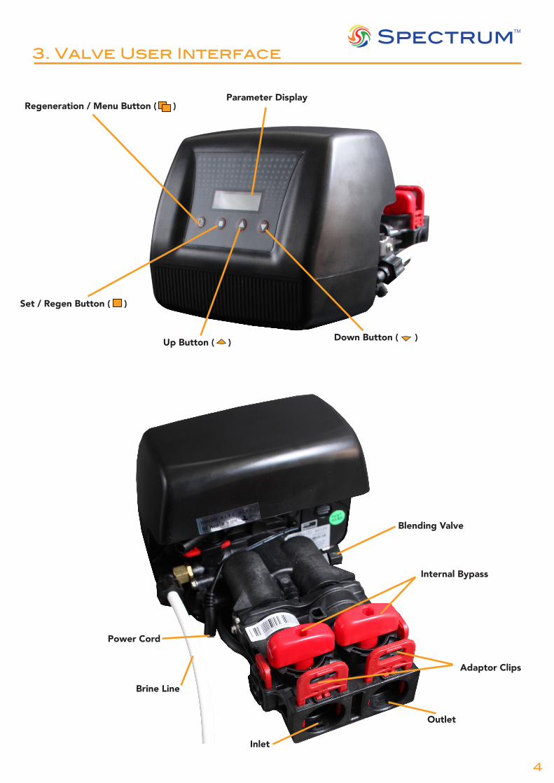
3. Valve User Interface
Parameter Display
Down Button ( )
Set / Regen Button ( )
Up Button ( )
Regeneration / Menu Button ( )
Internal Bypass
Adaptor Clips
Inlet
Outlet
Blending Valve
Brine Line
Power Cord

54
SpectrumTM
4. Installation Instructions
Water Pressure 2 - 8 bar
Electrical Supply Uninterrupted AC
Existing Plumbing Free of any deposits or build-ups inside pipes
Softener Location Locate close to drain & connect according to plumbing codes
Bypass Valves Always provide external bypass valve
Brine tank set-up
1. Fill the brine tank with the required amount of salt. The salt levels should be higher than the water level for the initial installation. There should be enough solid salt at anytime throughout the life of the softener.
2. Manually initiate a whole regeneration cycle to fill water in the brine tank to an appropriate level.
The Chrono water softener should be installed and prepared by a qualified person.
The system should be ready to use after the complete installation and a regeneration test. Any other operations are not necessary unless power supply is cut off accidentally.
Important:It is recommended to install a bypass system to ensure there is a constant water supply, in the event of potential softener failure or maintenence.
1. Place the softener cabinet close to a drain where the system will be installed. The surface should be clean and level.2. Perform all plumbing according to local plumbing codes.
• Use a ½" minimum pipe or tubing size for the drain line. However use a ¾" pipe or tubing for backwash flow rates that exceed 32lpm (UK gal) or where length exceeds 20ft (6m).
3. Use PTFE tape on the drain fitting and any solder joints near the valve, before connecting any piping. Always leave at least 6" (152mm) between the valve and joints when soldering pipes that are connected to the valve. Failure to do this could cause damage to the valve.
4. The softener is supplied with 1" inlet adaptors to fit. Lubricate the O-rings on the quick connect screw adaptors. Remove the locking clips and push the adaptors in to the bypass, then refit the 2 locking clips. (See Fig. A)
5. Now set the valve into the bypass position (See Fig. B) using the tool provided, rotating the handles until they are both perpendicular to the flow path of inlet and outlet. This procedure only needs carrying out with the tool on the first operation, to release the valve from the factory setting.
6. Return the valve to the service position (See Fig. C).7. Into the brine tank add water until it is above the air check.
Do not add salt to the brine tank at this time.8. Open the main water supply valve slowly to the ¼ open position
and let the water flow into the resin tank. If the valve is opened too rapidly then the resin may be lost.
9. When all of the air has been purged from the tank, water will begin to flow steadily to the drain. Fully open the main supply valve.
10. Open a tap that is linked to the softening system and let water run for a few minutes or until the system is free of foreign material resulting from the plumbing work. Close the water tap when the water runs clean.
Fig. C. Service PositionFig. B. Bypass Position
Fig. A. Bypass Assembly

SpectrumTM
6
4. Installation Instructions
The softener needs to be installed onto the mains water supply. It has an integrated bypass. Piping has to comply with the regulations of the country where it is installed.• Do not plug in the electrical feed before the
installation.• Ensure the stopcock is closed.• The piping of the inlet and outlet are 1” BSP.• The water needs to have a pressure between 2-8
bar and 4-42 degrees.• The softener has to be installed on a flat dry surface.• Electrical mains powered 220-240V AC 50Hz.• The soldering on the pipework has to be done before connecting the water softener as heating could damage the
water softener.• For residential purposes, it is essential to ensure that at least one drinking water tap is not connected to the
softener. Softened water has a high Sodium content which is to be avoided for people on low sodium or salt diets, and babies on infant formulas.
4.1. Connecting
1. Close the stop cock.2. Connect the drain Line to the the outside drain of the premises. It is necessary to fit an air gap device.The drain
piping should be as short as possible avoiding height of over 1.5 metres higher than the softener as well as lengths of over 5 metres.
3. Connect the inlet and outlets to the fitted plumbing.4. Close the bypass valves. Open the stopcock and open the water at the feed tap. This will allow any particles
to be removed from the system before operation. Let water run out of the tap until it is clear. Once done, close both the outlet tap and the stopcock to pursue further steps of the installation.
5. Manually fill the brine tank with water between 5 and 10 cm.6. Open the bypasses as well as the stopcock . You will hear the water flowing into the resin pressure vessel. When
there is no more water flowing in, open a cold water tap so that the excess air will purge out of the system. Once the air is removed, close the tap.
7. You can now switch on the valve electrical power.8. Press and hold the key “ ” for 3 seconds to initiate a manual regeneration. It will last between 30 minutes and 1
hour.Mains Out
PowerSupply
DrainHose
To Drain
Water Softener
In Out
Over�ow To Outside
Main Water Supply
MainsStopcock
Main WaterTap For
Drinking
Pressure Reducing Valve (if required)
Bypass Valve
Inlet TeeIncorporating Check Valve
Outlet Valve
InletValveInternal
Bypass
1
2 34
5
6
4
5
5
5
6 5
4
66
Water Pressure 2 - 8 bar
Electrical Supply Uninterrupted AC
Existing Plumbing Free of any deposits or build-upsinside pipes
Softener Location Locate close to drain & connect according to plumbing codes
Bypass Valves Always provide external bypass valve

76
SpectrumTM
5. Valve Initial Set-Up
5.1. Key Definition
Menu Key• Press this key to enter or exit the menu• Press and hold this key for 3 seconds to unlock keys locked at standby status.
Set / Regen Key• Press this key to select a program or to save the settings.• Press and hold the key for 3 seconds to initiate a manual regeneration at standby status.
Up & Down Key• Press the key to increase or decrease the value of the settings.• Press the key to enter the previous or the next menu.
Programing will return to standby status if a key is not pressed for 1 minute, after 3 minutes the keys will lock.
5.2. System Initialization
When power is first supplied, the valve may take about two minutes to initialize and the valve will show:
Any key will be overridden at this time. When the valve reaches the service position, it will display:
INITIALIZINGWAIT PLEASE
03:30PM Sept.1602/07 02:00
Regeneration Mode: Timer
Current Time Current Date
Regeneration Days Remaining Regen. Time
Regeneration Days
Water Pressure 2 - 8 bar
Electrical Supply Uninterrupted AC
Existing Plumbing Free of any deposits or build-upsinside pipes
Softener Location Locate close to drain & connect according to plumbing codes
Bypass Valves Always provide external bypass valve

SpectrumTM
8
5.3. Valve Set-up and Program Settings:
03:30PM Sept.1602/07 02:00
Timer Display Settings
SYSTEM LANGUAGE ENGLISH ESPAN
REGIONAL OPTION METRIC US
REGEN. MODETIMER
CURRENT DATESEP.XX.20XX
CURRENT TIMEXX:XX AM
REGEN. DAYSXX DAYS
BA.WA. DURATIONXX MINUTES
BRINE DURATIONXX MINUTES
RINSE DURATIONXX MINUTES
REFILL DURATIONXX.X MINUTES
LOAD DEFAULTCAPACITY / L M S /
REGEN. TIMEXX:XX AM
Parameter Options Action
1 SYSTEM LANGUAGE
1. Press and hold “ “ until the beep2. Press “ “ English is highlightedENGLISH
SPANISH
2 REGIONAL OPTION
METRIC3. Press “DOWN / “ then press “ “4. Press “UP / ” or “DOWN / ” buttons until
metric flashes5. Press “ “US
3 REGEN. MODE
TIMER6. Press “DOWN / “ Timer is highlighted, no
changes are availableMETER IMMEDIATEMETER DELAYED
MIX. REGEN
4 CURRENT DATE
7. Press “DOWN / “ then press “ “, the year will be highlighted
8. Press the “UP / ” or “DOWN / ” buttons to select the correct year
9. Press “ “ then the “UP / ” or “DOWN / ” buttons to change the month
10. Press “ “ then the “UP / ” or “DOWN / ” buttons to change the day
11. Press “ “
5 CURRENT TIME
12. Press “DOWN / “ then press “ “13. Press the “UP / ” or “DOWN / ” buttons to
input the current hour14. Press “ “ then “UP / ” or “DOWN / ” to
select the current minutes15. Press “ “
6 REGEN. TIME
16. Press “DOWN / “ then press “ “17. Press the “UP / ” or “DOWN / ” buttons to
set the hour of a regeneration18. Press “ “ then “UP / ” or “DOWN / ” to
set the minutes of a regeneration19. Press “ “
7 REGEN. DAYSNOTE:
Refer to Capacity chart (5.4.) to calculate number of days between 2 regenerations
20. Press “DOWN / “ then press “ “21. Press the “UP / ” or “DOWN / ” buttons22. Press “ “
8 BA.WA. DURATION 23. Press “DOWN / “
9 BRINE DURATION 24. Press “DOWN / “
10 RINSE DURATION 25. Press “DOWN / “
11 REFILL DURATION 26. Press “DOWN / “
12 LOAD DEFAULT
27. Press “DOWN / “ then press “ “28. Press the “UP / ” or “DOWN / ” buttons
until S is highlighted29. Press “ “30. The programming is complete
5. Valve Initial Set-Up

98
SpectrumTM
5. Valve Initial Set-Up
Number of days between 2 regenerationsCommercial:
Daily water usage (l): 150 275 365 450 520 600
Residential:No of people in the home: 1 2 3 4 5 6
100 7 7 7 7 7 7
120 7 7 7 7 7 7
140 7 7 7 7 7 7
160 7 7 7 7 7 7
180 7 7 7 7 7 6
200 7 7 7 7 6 5
220 7 7 7 7 6 5
240 7 7 7 6 5 5
260 7 7 7 6 5 4
280 7 7 6 5 4 4
300 7 7 6 5 4 4
320 7 7 6 5 4 3
340 7 7 5 4 4 3
360 7 7 5 4 3 3
380 7 6 5 4 3 3
400 7 6 4 4 3 3
420 7 6 4 3 3 3
440 7 5 4 3 3 2
460 7 5 4 3 3 2
480 7 5 4 3 3 2
500 7 5 4 3 3 2
600 7 4 3 2 2 2
5.4. Capacity chart to determine days between regenerations
Har
dnes
s le
vels
in p
pm C
aCO
3
REG.DAYS: 02/07REG.TIME 02:00A
5.5. Regeneration Enquiry
Press the key “ ”and “ ” simultaneously at the standby status, the screen will display different regeneration information at different regeneration mode.
SELECT: Timer• The first screen shows the days remaining (02) of one regeneration cycle, in days.
“07” refers to regeneration cycle in days.• The second screen shows regeneration time, “A” refers to a.m., “P” refers to p.m.

SpectrumTM
10
Press and hold the key “ ” for 3 seconds to unlock keys.Press and hold the key “ ” for 3 seconds to initiate a manual regeneration.Screen will display:
“BACKWASHING” starts flashing, when the valve reaches the BACKWASH position. The vertical bars onscreen will decrease as the regeneration progresses.
Once the BACKWASH has completed the valve automatically moves onto the next cycle - “BRINING” and the screen (shown right) will be displayed.
The valve will then advance to the rest of the regeneration cycles RINSE and REFILL.
NOTE: should you need to move on from any cycle before it completes processing any key will automatically advance the valve to the next cycle position.
BACKWASHING| | | | | | | | | | |
BRINING| | | | | | | | | | |
6. Manual Regeneration
7. Water Hardness Adjustment
Users can adjust the mixing valve to get their desired water hardness at the outlet.
Operation methods:
• Rotate the mixing valve in a clockwise direction. The bigger rotation angle, the higher water hardness.

1110
SpectrumTM
Once the softener has been installed and setup by a professional, there are some useful functions to be aware of.
Salt replenishment: when the softener runs out of salt, it will not produce any more soft water. It is therefore impor-tant to keep it topped-up, this is done via the lid of the top of the softener. Salt should always be visible over the line of water in the cabinet but the total volume of salt and water should not exceed the overflow level.
NOTE: ONLY USE GRANULATED OR TABLET SALT DEDICATED TO WATER SOFTENERS
Bypass: The Bypass is a function which makes the water softener offline. This is useful when soft water is not required (e.g. using a hosepipe)
In the service position, the softener will produce soft water.In the Bypass position, the water will not go through the resin tank and remain as hard water.
Blending valve: This can be used optionally when some applications require a certain level of hardness. When the blending valve is closed (Fully turned anticlockwise), you will get 100% soft water. The more you open it (turning clockwise), the harder the water will get. Refer to Section 3 for blending valve position.
Display: In service, the valve will display time of day and the number of days left until the next regeneration.
Regeneration is a standard process required to recharge the resin contained inside the softener. The regeneration will happen at the time set in the program. A motor noise can be heard when the softener is in regeneration mode, this is normal.
The screen will display the various cycles of the regeneration and will then go back to service mode.
• Backwashing• Brining• Rinse• Refill
Power Cuts: In the event of a power cut the Chrono will keep its settings in memory for up to 48 hours. After 48 hours reprogramming may be necessary, please refer to section 5.3 for ‘Valve Set-up’ and ‘Program Settings’.
Downtime: After holidays, or a long period without using water over a week, it is recommended to initiate a manual regeneration in order to flush the resin tank. During this time only hard water will be available. Refer to section 6 for instructions.
8. End User Instructions
Service PositionBypass Position
03:30PM Sept.1602/07 02:00
Current Time Current Date
Regeneration Days Remaining Regen. Time
Regeneration Days
Lid
Overflow

SpectrumTM
12
Problem Possible Cause Possible Solution
A. Controller does not work
1. Power off 2. Transformer is not plugged in3. Defective power cord4. Defective transformer
1. Switch on power2. Connect to constant power source3. Replace cord4. Replace the transformer
B. Incorrect time of regeneration 1. Power outage causes inaccurate timing 1. Reset the timer
C. Leaking 1. Loose connections 1. Tighten joints
D. Noisy 1. Air pressure in the system 1. Re-backwash the system to vent air
E. Milk-white water 1. Air exists in the system 1. Turn on the tap to vent air
F. Unsatisfied water hardness1. Poor raw water quality2. Time of regeneration is too long3. Resin disabled
1. Contact your supplier for assistance2. Reset time of regeneration3. Re-regeneration or use new resin
G. Softener fails to use salt 1. Water pressure is too low2. Brine line blocked3. Injector is blocked4. Internal control leak
1. Line pressure must be at least 20 psi2. Clean brine line3. Clean or replace injector & screen4. Check piston, seals and spacers
H. Brine container overflow 1. Refill time too long 1. Contact your supplier for assistance
I. Water hardness remains1. Fail to regenerate automatically2. Brine concentration is poor3. Injector is plugged
1. Check power of controller2. Keep brine tank full of salt3. Disassemble the injector and clear it by washing with water
K. Untreated water leakage during service
1. Improper regeneration2. Leaking of bypass valve3. O-ring around riser tube damaged4. Incorrect regeneration cycle setting
1. Repeat regeneration making certain that the correct salt dosage is set2. & 3. Replace O-ring4. Reset regeneration cycle
9. Troubleshooting
Important Notice
The controlling components are driven by an electric circuit. Some programmed parameters will be lost if a power outage lasts over 8 hours and the water softener will carry out the regeneration process at the incorrect time. We strongly recommend that after a power outage, users should check the time and adjust accordingly.
9.1. Chrono System

1312
SpectrumTM
9. Troubleshooting
9.2. Chrono Valve
Problem Possible Cause Possible Solution
A. Unit fails to initiate a regeneration cycle
1. No power supply Check electrical service, fuse, etc
2. Power Failure Reset time of day
B. Water is hard
1. By-pass valve open Close by-pass valve
2. Out of salt Add salt to tank
3. Plugged injector / screen Clean parts
4. Flow of water blocked to brine tank Check brine tank refill rate
5. Leak between valve and central tube Check if riser tube is cracked or o-ring is damaged. Replace faulty parts
6. Internal valve leak Replace valve seals, spacer and piston assembly
C. Salt use is high 1. Refill time is too long Check refill time setting
D. Low water pressure
1. Iron or scale builds up in line feeding unit Clean pipes
2. Iron build up inside valve or tank Clean control and add resin cleaner to clean the bed. Increase regeneration frequency
3. Inlet of control blocked due to foreign matter Remove piston and clean control valve
F. Too much water in brine tank
1. Blocked injector or screen Clean parts
2. Foreign material in brine tank Clean parts
G. Unit fails to draw brine
1. Drain line flow control is blocked Clean parts
2. Injector or screen is blocked Clean parts
3. Inlet pressure too low Increase pressure to 25 PSI
4. Internal valve leak Replace seals, spacers and piston assembly
H. Valve continuously cycles 1. Broken Gear Replace faulty parts
I. Flows to drain continuously
1. Valve settings incorrect Check valve settings
2. Foreign material in control valve Clean control
3. Internal leak Replace seals, spacers and piston assembly

SpectrumTM
14
10. Cautions
1. Without reading and understanding the contents of this user manual, DO NOT perform any operations on the control valve.
2. Strictly prohibit a leaning position when shipping, installing and using this product as this could cause damage.3. During the regeneration, water from the tap will NOT be softened. It is NOT recommended to use water during
regeneration; otherwise a negative effect on the regeneration result will occur.4. Initiate a regeneration cycle when the softener has been inactive for a long period of time and then turn on the
tap for several minutes before resuming normal use.5. Do not disconnect power during service to prevent timer distribution.6. If water usage or hardness of raw water dramatically increases (compared to the normal usage), then the frequency
of regeneration should increase.7. Hot water could cause severe damage to the softener system, for water boiler and water heaters users, ensure the
total-run of the piping between the softener and the boiler is not less than 3 meters. It is recommended to install a check valve between the filter and the boiler if unable to meet the required piping length.
8. The input water pressure must be between 2 - 8 bar.9. No chemicals should be present at the inlet and outlet connecting sectors.10. Besides the system, spare part connection materials are not included in the scope of the manufacturer’s warranty.11. The required environmental temperature for a softener is 1 - 42°C. Below this will cause the softener to malfunction.12. Do not apply pressure to the softener.13. Indoor installation is preferred. Avoid exposure to direct sunlight, radiation from other heating sources and avoid
extreme weather conditions including rain and snow.14. Use salt granules or tablets designed for softeners.15. No tools should be used for connecting the plastic parts as over tightening or excessive force could result in
damage.16. If necessary use food grade silica sealant for lubricating rubber O-rings.17. Only qualified personnel should adjust or remove the adaptor locking clips on the reverse of the valve, as this can
tamper with the valve settings. Should this be required pressure must firstly be discharged from inside the water softener.

1514
SpectrumTM
11. System Parts
11.2. Drain Line Flow Controls (DLFC) & Injector:
Replacing Injector and DLFC according to the following picture:
11.1. Valve Powerhead Assembly
SpectrumTM
16
11. System Parts
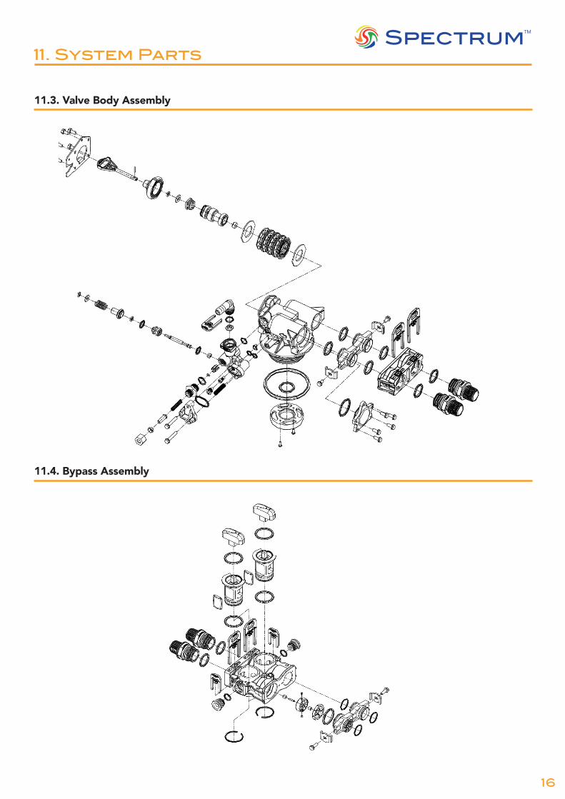
11.3. Valve Body Assembly
Filter Injector Option
11.4. Bypass Assembly

1716
SpectrumTM
12. Technical Information
Maximum Operating Temperature (ºC) 42
Minimum Operating Temperature (ºC) 1
Maximum Operating Pressure (bar) 8
Minimum Operating Pressure (bar) 2
Hydrostatic Test Pressure (bar) 24.15
Resin Volume (l) 13
Max Flow Rate (m3/hr) 4.5
Nominal Flow Rate (m3/hr) 0.5
Inlet / Outlet (") 1 BSP
Pressure Tank Thread (") 2.5 NPSM
Valve Timeclock Downflow
Power Requirements 230V AC
Electrical Adaptor Input: AC240V, 50Hz / 60HzOutput: AC12V
Salt Consumption Per Regeneration (kg) 1.4
Water Consumption Per Regeneration (l) 80
Salt Storage (kg) 10
Cabinet Width (mm) 330
Cabinet Depth (mm) 470
Cabinet Height (mm) 660
Riser Pipe Diameter Required (mm) 26.7