Neuron-Spectrum-AM TM 002 final
59
Technical Manual Neuron-Spectrum-AM Ambulatory EEG and PSG system TM053.01.002.000 (20.09.2014)
Transcript of Neuron-Spectrum-AM TM 002 final

Technical Manual
Neuron-Spectrum-AM
Ambulatory EEG and PSG system
TM053.01.002.000(20.09.2014)

Neurosoft Ltd. © 2014 5, Voronin str., Ivanovo, 153032, Russia P.O. Box 10, Ivanovo, 153000, Russia Phone: +7 (4932) 24-04-34 Fax: +7 (4932) 24-04-35 E-mail: [email protected] Internet: www.neurosoft.ru

3
Contents
Contents ...................................................................................................................... 3
Introduction................................................................................................................. 5
1. Description and Principle of Operation............................................................. 6 1.1. Function.......................................................................................................... 6 1.2. Main Specifications ........................................................................................ 7 1.3. Delivery Set .................................................................................................. 10 1.4. Technology and Operation ........................................................................... 13 1.5. Connectors and Indicators ........................................................................... 17 1.6. Display.......................................................................................................... 19
2. Mounting and Installation................................................................................. 20 2.1. Requirements to the Personnel Conducting Mounting and Installation........ 20 2.2. Room Selection and Placement ................................................................... 20 2.3. Unpacking and Check of Delivery Set.......................................................... 22 2.4. Assembly and Connection to Computer....................................................... 23
3. Proper Use ......................................................................................................... 25 3.1. Safety Measures when Using System.......................................................... 25 3.2. Setting-up Procedures.................................................................................. 26 3.3. Memory Card Installation ............................................................................. 27 3.4. Basic Principles of Work with Menus and Entry Fields ................................ 27 3.5. Menu Commands ......................................................................................... 29
3.5.1. Switch Off the System ......................................................................... 29 3.5.2. Record Statistics.................................................................................. 29 3.5.3. Record Stop......................................................................................... 29 3.5.4. New Exam Creation............................................................................. 29 3.5.5. Impedance Check................................................................................ 29 3.5.6. Record Start......................................................................................... 33 3.5.7. Wireless Network................................................................................. 33 3.5.8. Options ................................................................................................ 35 3.5.9. Date and Time ..................................................................................... 35 3.5.10. Language........................................................................................... 36
3.6. Troubleshooting............................................................................................ 36 3.7. Actions in Emergency................................................................................... 37
4. Servicing ............................................................................................................ 37 4.1. General Requirements ................................................................................. 37 4.2. Maintenance Service.................................................................................... 38 4.3. Firmware Update.......................................................................................... 38 4.4. Conservation ................................................................................................ 38
5. Current Repair ................................................................................................... 39 5.1. General Requirements ................................................................................. 39 5.2. Repair of EEG Cables, ECG Cables, Adapters and Linkers ........................ 39 5.3. Breath Sensor Repair................................................................................... 39 5.4. Electrode Cap Repair ................................................................................... 40

Neuron-Spectrum-AM (Technical Manual)
4
6. Packing and Transportation............................................................................. 40
7. Utilization ........................................................................................................... 41
8. Delivery Set and Package Data ........................................................................ 41
9. Acceptance Certificate...................................................................................... 41
10. Delivery Certificate............................................................................................ 41
11. Storage Data ...................................................................................................... 42
12. Warranty............................................................................................................. 43
13. Reclamation Data .............................................................................................. 44
14. Repair Data ........................................................................................................ 46
Annex 1. Electromagnetic Emissions and Immunity ............................................ 47
Annex 2. Description, Configuration and Setup of Wireless Networks............... 51
Annex 3. Memory Card File Storage Structure ...................................................... 59
5
Introduction
This technical manual (hereinafter referred to as “manual”) is the document describing operation and servicing of Neuron-Spectrum-AM ambulatory EEG and PSG system (hereinafter referred to as “system”).
This manual is the document which certifies the system specifications guaranteed by the manufacturer.
Do not start working with system before you have read this document!
You can send your responses and recommendations to Neurosoft Company by
the following address:
P.O. Box 10, Ivanovo, 153000, Russia
or by e-mail:
You can find additional information on Neurosoft products in the Internet:
www.neurosoft.ru
or ask questions by phones:
+7 (4932) 24-04-37; +7 (4932) 59-21-12 (Service department),
+7 (4932) 24-04-34; +7 (4932) 95-99-99.
You can also contact SAS Neuromed Company, Authorized European Representa-tive of Neurosoft Company (Mr. Pierre Scholl) by the following address:
Chemin du tomple
84330 Le Barroux, France
Phone: +490-650-470, +622-748-384
Fax: +490-650-470
E-mail: [email protected]

Neuron-Spectrum-AM (Technical Manual)
6
1. Description and Principle of Operation
1.1. Function
Ambulatory EEG and PSG system Neuron-Spectrum-AM is meant for long-term elec-troencephalogram (EEG), electromyogram (EMG), electrooculogram (EOG), electro-cardiogram (ECG), blood supply indexes, respiratory and motion activity recording in any unshielded room.
The system is not intended to allow direct diagnosis or monitoring of vital physiological processes, where the nature of variations could result in immediate danger to the patient for instance variations in cardiac performance, respiration, activity of central nervous system.
The system is portable and can record simultaneously:
up to 161 EEG channels;
up to 2 EOG channels;
up to 4 EMG channels;
1 ECG channel;
1 blood supply indexes channel (oxygen saturation, photoplethysmogram, heart rate, blood supply);
up to 4 breath channels (2 channels for abdominal and thoracic excursion pie-zoelectric sensors, 1 channel for airflow thermistor sensor, 1 channel for air-flow pressure sensor);
1 channel for snoring sensor;
1 channel for sensors with direct current output.
If it is necessary, EOG, EMG and ECG channels can be used for EEG recording.
The system can be used in medical and prophylactic institutions, diagnostics centres, neurosurgical clinics and experimental laboratories of research institutions for:
brain functional state study;
epilepsy diagnostic;
1 The number of EEG channels monitored simultaneously can be increased to 21 in case of using EOG and 3 EMG channels for EEG signal recording.

Description and Principle of Operation
7
detection of generalized, inflammatory and vascular brain processes and local-ization of pathological activity sources;
polysomnographic studies.
It is possible to work in the long-term EEG monitoring mode or EEG videomonitoring mode.
During EEG acquisition the system provides:
video registration from one, two or three cameras and audio registration from one or two microphones;
cerebral function monitoring and amplitude-integrated EEG (aEEG) analysis;
polysomnogram recording and analysis;
surface EMG recording;
amplitude, frequency spectral, periodometric, correlative and coherent EEG analysis, wavelet analysis, independent component analysis, epileptiform ac-tivity detection (spikes and sharp waves);
3-D dipole localization of pathological activity sources (if BrainLoc or LORETA software is installed);
exam report generation;
file export and import with the use of EDF and EDF+ standard data inter-change formats;
review, store and print of the recorded traces, results of their analysis and exam reports.
The main requirement for the digital system application is the sufficient medical staff qualification.
1.2. Main Specifications Table 1. Main Specifications
Parameters Values
EEG, EMG, EOG and ECG Channels
Number of channels 23
Input range 2–12000 µV
Ratio error of voltage measurement: in the range from 10 up to 50 µV in the range from 51 up to 12000 µV
within ±25% within ±7%

Neuron-Spectrum-AM (Technical Manual)
8
Table 1. Continued
Parameters Values
Ratio error of time interval measurement in the range from 10 µs up to 10 s
within ±2%
High pass filter 0.05, 0.5, 0.7, 1.5, 2, 5, 10 Hz
Low pass filter 5, 10, 15, 35, 75, 100, 150, 200, 250, 500 Hz
Sweep speed 3, 7, 15, 25, 30, 50, 60, 120, 240, 480, 960 mm/s
Input noise level in the range from 0.5 to 35 Hz (rms value)
not more than 2 µV (not more than 0.35 µV)
Input impedance not less than 400 MΩ
Snoring Sensor Channel
Number of channels 1
Piezoelectric Breath Sensor Channel
Number of channels 2
Thermistor Breath Sensor Channel
Number of channels 1
SpO2 Channel
Number of channels 1
Measurement time not more than 15 s
Operating principle light absorption of two wavelength
Absolute error of SpO2 measurement: in the range from 75 to 100% in the range from 0 to 75%
±2%
not defined
% SpO2 measurement range 0 –100%
Direct Current Channel
Number of channels 1
Voltage measurement range from –10 to +10 V
Light Sensor Channel
Number of channels 1
General Specifications and Parameters
Interface IEEE-802.11b,g; USB
Built-in memory type and capacity SD(up to 2 GB), SDHC(up to 32 GB)
Supply voltage: electronic unit Desktop PC-based system Notebook PC-based system
(4,8÷6) V (4 АА batteries)
220/230 V AC (50 Hz) 220/230V AC (50 Hz) / int. battery
Single unit operation from one battery set (without wireless connection)
not less than 24 hours
Electronic unit overall dimensions 1409535 mm

Description and Principle of Operation
9
Table 1. Continued
Parameters Values
Electronic unit weight (without batteries) not more than 0.5 kg
Delivery set weight (without computer and printer) not more than 12.2 kg
Working parts BF type
Safety and Electromagnetic Compatibility
Electromagnetic compatibility (EMC) is ensured by fulfilment IEC 60601-1-2:2007 re-quirements. The system is intended for operation in electromagnetic environment de-scribed in Annex 1.
Portable and mobile RF communication equipment may affect the system work.
The use of the equipment not listed in tables 2 - 5 of this technical manual may result in increased emission and system decreased immunity.
As for safety, each digital system satisfies IEC 60601-1:1988+A1:1991+A2:1995, IEC 60601-1-1:2000, IEC 60601-2-26:2002 and IEC 60601-2-40:1998 requirements. The electronic unit is supplied by internal power supply; it has double isolation and BF type work parts according to IEC 60601-1.
Wireless Communication Interface
The electronic unit is intended for operation in wireless local area networks (Wi-Fi) of IEEE 802.11 standard.
The system ensures compatibility with networks which satisfy 802.11b/g/n require-ments.
The electronic unit supports 2 frequency ranges: 2.4 GHz (1-13 channels) and 5 GHz (36-140 channels). Maximum emissive power is +17 dBm.
The system supports following authentication and encryption methods: No encryp-tion/WEP64/128-Open connection, WEP64/128-Shared Secret, TKIP-WPA PSK, AES/CCMP-WPA2 PSK.
Interpretation of symbols on the electronic unit:
Attention: consult user and technical manuals.
Work parts of BF type according to IEC 60601-1.
The system has RF transmitter.
Mark of conformance to 93/42/EEC “Concerning Medical Devices” directive.
Mark of conformance to 2012/19/EC “On waste electrical and electronic equipment (WEEE)” directive.

Neuron-Spectrum-AM (Technical Manual)
10
1.3. Delivery Set
The delivery set of Neuron-Spectrum-AM ambulatory EEG and PSG system includes electronic unit with different electrode sets for EEG, polygraphic channels and soft-ware which can be delivered to a customer both jointly and separately, and also com-ponents and bought articles (Table 2 and Table 3).
Table 2. Base Delivery Set
Name Document code or main specifications
Number, pcs.
Neuron-Spectrum-AM electronic unit NSFT 053201.001 NSFT 053201.002
1
Memory card SD, 4Gb 1
Router 1) DIR 620 (D-Link Corporation, Taiwan)
1
External power supply unit with four rechargeable batteries of AA type (R6) and ≥2000 mAh capacity 1)
GP PowerBank Smart 2 (model GP PB14)
1
Neoprene belt 2) NSFT 053211.003 NSFT 053211.003-01
NSFT 053211.005 NSFT 053211.005-01
1 1
Pouch for electronic unit 3) NSFT 053213.002 NSFT 053213.003
1
Set of belts NSFT 053211.004 NSFT 053211.004-01
1
Electrode system for long-term EEG recording 1): Electrode cap for 20-channel EEG recording
(MCScap23) Strap for electrode cap MCScap Set of removable electrodes for MCScap (10
pcs.) Spare EEG electrode for MCScap Ear adapter for MCScap Special needle for electrodes filling with gel Electrode gel (bottle with dispenser 250 g).
MCSCap26 (Medical Computer Systems Ltd,
Zelenograd)
1
Male Luer Integral Lock Ring, 1/8" (3.2 mm) Value Plastics Inc. 1
Software on CD:
Neuron-Spectrum.NET software without additional modules 1
Operational Documentation:
Neuron-Spectrum-AM technical manual TM053.01.002.001 1
Neuron-Spectrum.NET user manual UM015.02.009.000 1
Exams Manager appendix to user manual AU999.01.002.003 1
Note: 1) The accessories and consumables of analogous types can be used if their application is permitted in the country.
Description and Principle of Operation
11
2) Neoprene belts NSFT 053211.003 and NSFT 053211.003-01 are supplied for NSFT 053201.001 elec-tronic unit, and neoprene belts NSFT 053211.005 and NSFT 053211.005-01 - for NSFT 053201.002 electronic unit. 3) Pouch for electronic unit NSFT 053213.002 is supplied for NSFT 053201.001 electronic unit, and NSFT 053213.003 – for NSFT 053201.002 electronic unit.
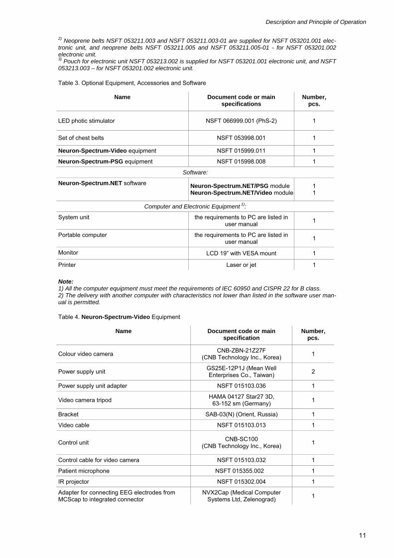
Table 3. Optional Equipment, Accessories and Software
Name Document code or main specifications
Number, pcs.
LED photic stimulator NSFT 066999.001 (PhS-2) 1
Set of chest belts NSFT 053998.001 1
Neuron-Spectrum-Video equipment NSFT 015999.011 1
Neuron-Spectrum-PSG equipment NSFT 015998.008 1
Software:
Neuron-Spectrum.NET software Neuron-Spectrum.NET/PSG module Neuron-Spectrum.NET/Video module
1 1
Computer and Electronic Equipment 1):
System unit the requirements to PC are listed in user manual
1
Portable computer the requirements to PC are listed in user manual
1
Monitor LCD 19” with VESA mount 1
Printer Laser or jet 1
Note: 1) All the computer equipment must meet the requirements of IEC 60950 and CISPR 22 for B class. 2) The delivery with another computer with characteristics not lower than listed in the software user man-ual is permitted.
Table 4. Neuron-Spectrum-Video Equipment
Name Document code or main specification
Number, pcs.
Colour video camera CNB-ZBN-21Z27F
(СNB Technology Inc., Korea) 1
Power supply unit GS25E-12P1J (Mean Well Enterprises Co., Taiwan)
2
Power supply unit adapter NSFT 015103.036 1
Video camera tripod HAMA 04127 Star27 3D,
63-152 sm (Germany) 1
Bracket SAB-03(N) (Orient, Russia) 1
Video cable NSFT 015103.013 1
Control unit CNB-SC100
(СNB Technology Inc., Korea) 1
Control cable for video camera NSFT 015103.032 1
Patient microphone NSFT 015355.002 1
IR projector NSFT 015302.004 1
Adapter for connecting EEG electrodes from MCScap to integrated connector
NVX2Cap (Medical Computer Systems Ltd, Zelenograd)
1

Neuron-Spectrum-AM (Technical Manual)
12
Table 4. Continued
Name Document code or main specification
Number, pcs.
Video capture card USB 1
USB extension cable Omix 20 m (Uniqueics Ltd, Russia)
NSFT 007998.003 1
Extension cable NSFT 015103.035 1
Table 5. Neuron-Spectrum-PSG Equipment
Name Document code or main specification
Number, pcs.
Cup electrode with cable (for EEG recording) 1) NSFT 990106.027-01.10 9
Cup electrode with cable (for EOG recording) 1) NSFT 990106.027-01.10 2
Cup electrode with cable (for EMG recording from chin) 1)
NSFT 990106.027-01.10 2
Cup electrode with cable (for ECG recording) 1) NSFT 990106.027-01.10 2
EP electrode with cable (for limb movement recording) 1)
NSFT 990106.027-01.15 4
Airflow thermistor sensor 1) NSFT 990351.006 (ATS-5/V) NSFT 990351.006-01 (ATS-5/D)
1
Snoring sensor 1) NSFT 990356.006-01 (SS-1-08) 1
Chest and abdominal respiratory efforts sensor 1) NSFT 990998.020-02 (APS-4-05) 2
Finger sensor for SpO2 recording (adult) 1) should meet Nellcor standard 1
Video capture card USB 1
Video camera CNB-ZBN-21Z27F (СNB Technology Inc., Korea)
1
Power supply unit GS25E-12P1J (Mean Well Enterprises Co., Taiwan)
2
Power supply unit adapter NSFT 015103.036 1
Video camera tripod HAMA 04127 Star27 3D, 63-152 sm (Germany)
1
Bracket SAB-03(N) (Orient, Russia) 1
Video cable NSFT 015103.013 1
Control unit CNB-SC100 (СNB Technology Inc.,
Korea) 1
Control cable for video camera NSFT 015103.032 1
Patient microphone NSFT 015355.003 1
IR projector NSFT 015302.004 1
Extension cable NSFT 015103.035 1
Nasal cannula Zhejiang Baite Medical Appliances Co, Ltd (China)
1
Male Luer Integral Lock Ring, 1/8" (3.2 mm) Luer 1/8” (3,2 mm) (Value Plastics Inc, USA)
1
Medical tape 1) Transpore (3M Company, 3M Health Care, USA)
1
Electrode adhesive paste 1) TEN20, 114 g (USA) 1
Note: 1) The accessories and consumables of analogous types can be used if their application is permitted in the country.

Description and Principle of Operation
13
1.4. Technology and Operation
Ambulatory EEG and PSG system operation is based on the acquisition, saving on built-in memory card and input of brain biopotentials and other physiological signals into PC for the analysis.
The system consists of PC and electronic unit. Electronic unit performs acquisition, saving on removable memory card and transfer of brain biopotentials and additional information recorded with the use of electrodes and sensors connected to the elec-tronic unit. PC with the installed Neuron-Spectrum.NET software performs input, analysis and long-tem storage of the acquired signals. All the data may be transferred from electronic unit to PC using SD or MMC memory card or wireless network which satisfies the requirements of IEEE802.11b/g (Wi-Fi) standard. To use wireless con-nection, PC should be connected to the local network with hotspots or equipped with wireless network adapter.
The electronic unit operates in wireless networks which satisfy the requirements of IEEE802.11b/g standard in infrastructure and ad hoc modes. Electronic unit setup for wireless operation is performed using controls located on it. Electronic unit can be connected to existing wireless networks.

Neuron-Spectrum-AM (Technical Manual)
14
The block diagram of the ambulatory EEG and PSG system is shown in Fig. 1.
Fig. 1. The block diagram of the ambulatory EEG and PSG system.
Electronic unit consists of control unit, amplifier unit, electrode and sensor connectors and batteries.
Slots for electrode and sensor connection (X3) are located on the side switchboard panel. Designations of corresponding slots on the electronic unit case are shown in Fig. 1.
Most of electric circuits for electrode connection are duplicated on the X1 slot of D-SUB type. This slot is meant for electrode cap connection and has corresponding con-tact configuration. The numbers of contacts and corresponding circuits are shown in Fig. 1.
X2 slot is meant for pulse oxymeter sensor connection and is located on the opposite side from the side switchboard panel.

Description and Principle of Operation
15
Screw pneumatic connector PS is meant for pneumatic breath sensor connection.
Amplifier unit is meant for electrode and sensor signal amplification, AD conversion and encryption.
А1..А24 differential AC amplifiers are meant for biopotential amplification.
The referent commutator consists of the set of electronic switches and is meant for signal selection. The selected signal will be transferred to the input of REF1 and REF2 referent buses. Switching circuit is organized in such a way that REF1 referent bus could receive signals from electrode connected to М1 connector or from any other electrode connected to the Fp1, F3, C3, P3, O1, F7, T3, T5, Fp2, F4, C4, P4, O2, F8, T4, T6, Fpz/EOGR, Fz/EOGL, ECG+, EMG1+, EMG2+/Pz, LML and LMR connectors. REF2 referent bus could receive signals from electrode connected to М2 connector or to any connector listed above.
S1 electronic switch is meant for input signal selection of A25 processing amplifier (designation chain of patient’s potential). This chain improves in-phase rejection. Sig-nals from REF1 and REF2 referent buses could be input signals for this chain. The chain can be disconnected by linking its input to the common conductor.
S2 and S3 electronic switches choose reference signal for А1..А8 and А9..А16 ampli-fiers respectively. Signals from REF1 and REF2 referent buses could be these refer-ence signals.
The signals gained by А1..А8 and А9..А16 amplifiers are transferred to the inputs of ADC1 and ADC2 AD converters and are converted into digital format.
S4 electronic switch chooses reference signal for A17 and A18 amplifiers. These am-plifiers are meant for Fpz/EOGR and Fz/EOGL electrode signal amplification respec-tively. Signals from REF1 and REF2 referent buses could be these reference signals. The signal from the amplifiers outputs is transferred to 1st and 2nd ADC3 inputs.
A19 amplifier gains potential difference between REF1 and REF2 referent buses. The gained signal from its output is transferred to the 3rd ADC3 input.
S5 electronic switch choose the reference signal for A20 amplifier. A20 amplifier is meant for ECG+ connector signal gaining. Signals from REF1 and REF2 referent buses or ECG- electrode signal could be these reference signals. The signal from the amplifier output is transferred to the 4th ADC3 input.
S6 electronic switch choose the reference signal for A21 and A22 amplifiers. These amplifiers are meant for gaining signals from EMG+ and EMG2+/Pz connectors. Sig-nals from REF1 and REF2 referent buses or EMG- electrode signal could be these reference signals. The signal from the amplifier output is transferred to the 1st and 2nd ADC4 inputs.
S7 electronic switch choose the reference signal for A23 amplifier. This amplifier is meant for gaining signals from Oz/LML+ connector. Signals from REF1 and REF2

Neuron-Spectrum-AM (Technical Manual)
16
referent buses or LML- electrode signal could be these reference signals. The signal from the amplifier output is transferred to the 3rd ADC4 input.
S8 electronic switch choose the reference signal for A24 amplifier. This amplifier is meant for gaining signals from Cz/LMR+ connector. Signals from REF1 and REF2 referent buses or LMR- electrode signal could be these reference signals. The signal from the amplifier output is transferred to the 4th ADC4 input.
A25 amplifier is meant for thermistor airflow sensor signal acquisition and amplifica-tion. Airflow thermistor sensor is plugged into FLOW+ and FLOW- connections on the side switchboard panel. The gained signal from the A25 amplifier output is transferred to the 1st ADC5 input.
A26 amplifier is meant for piezoelectric snoring sensor signal acquisition and amplifi-cation. Airflow thermistor sensor is plugged into SNORE+ and SNORE- connections on the side switchboard panel. The gained signal from the A26 amplifier output is transferred to the 2nd ADC5 input.
A27 and A28 amplifiers are meant for piezoelectric excursion sensor signal acquisition and amplification. Piezoelectric excursion sensor is plugged into CHEST+, CHEST-, ABDOM+ and ABDOM- connections on the side switchboard panel. The gained sig-nals from the outputs of A27 and A28 amplifiers are transferred to the 3rd and 4th ADC5 inputs.
A29 amplifier is meant for signals acquisition from sensors of the third-party manufac-turers with the DC output signal. These sensors are plugged into DC+ and DC- con-nections on the side switchboard panel. The gained signal from the A29 amplifier out-put is transferred to the 5th ADC5 input.
ACC built-in acceleration indicator allows to detect the electronic unit position and to estimate patient’s motor activity if the electronic unit is attached on patient’s body. The signal from the ACC output is transferred to the 6th ADC5 input.
Airflow pressure sensor is connected to PS pressure sensor through AS connector. PS converts airflow sensor signals into the electrical and transfer it to the 7th ADC5 in-put.
Pulse oximeter sensor is connected to the X2 slot. To control the sensor work use “Communication module of pulse oximeter sensor”.
MC1 microcontroller receives data from ADC1-ADC5 and “Communication module of pulse oximeter sensor”, pack them removing the redundant data and sent packets to the control unit. Besides, MC1 set the switches of unspecified referent commutator according to exam template created by the user.
Control unit contains MC2 microcontroller, firmware of which control the whole sys-tem. In the registration mode MC2 apply power to the amplifier unit and transmit con-figuration information to its MC1 microcontroller.

Description and Principle of Operation
17
Information on current work mode, diagnostic and informational messages are dis-played on the built-in liquid crystal display.
Electronic unit control is operated with the help of menu, using keyboard.
All the data transmitted to the MC2 from the data receive unit are saved as files on memory card.
Wi-Fi radio module allows MC2 to receive commands and to translate acquired data via wireless network to PC.
The light sensor (is supplied only with units NSFT 053201.002 and above) allows to measure the illuminance level of front panel. Light passes through the small translu-cent window located on the front panel of electronic unit and through the optic fiber it is delivered to the sensor fixed on the control board.
Voltage converter powers all system units getting energy from batteries.
During the acquisition electronic power supply of unusable system units switches off automatically in order to minimize system power consumption and maximize working time from one battery pack.
The PC helps to perform signal processing, signal displaying, its presentation in dif-ferent modes after mathematical analysis, storing of the EEG traces on the hard disc, exam report generation and printing.
1.5. Connectors and Indicators
The front and side panels of the electronic unit are shown in Fig. 2.
Fig. 2. The front and side panels of the electronic unit.

Neuron-Spectrum-AM (Technical Manual)
18
The front panel of the electronic unit contains monochrome liquid crystal display (1), power button (2), three menu navigation buttons (3), light sensor (9) (only for NSFT 053201.002 electronic units and above) and battery compartment cover. SD/MMC memory card slot (4) is located on the battery compartment upper wall. Memory card is available only if batteries (5) (are not shown for convenience) are extracted from the battery compartment. The battery compartment cover is not shown in Fig. 2 for con-venience.
Batteries should be extracted only after exam recording was stopped using the corre-sponding display menu item or Neuron-Spectrum.NET software.
Display menu is intended to control all functions of the electronic unit, namely: wire-less connection setup, exam recording start and stop, work with memory card.
DB-25 slot (6) on the upper unit panel is meant for electrode cap connection.
Side switchboard panel (see Fig. 2) is meant for connection of electrodes and sensors with touch-proof connectors. Each switchboard panel connector has marking with its functional purpose which agrees with its designation on functional scheme of elec-tronic unit.
DB-9 slot (7) on the side panel of the unit case is meant for SpO2 sensor connec-tion (see Fig. 2).
Screw pneumatic connector (8) located above DB-9 slot is meant for airflow pressure sensor (nasal cannula) connection.
Table 6. Electronic Unit Controls and Neuron-Spectrum.NET Corresponding Menu Commands.
Button Purpose
[On] button
- to switch the system on; - to acquire patient’s event during the exam.
[Up] and [Down] buttons
- to move along the menu; - to move between dialog elements; - to move the carriage in the input field; - to move between pages of the list.
[OK] button
- to choose the current menu item; - to choose the current dialog element; - to enter symbol into the text input field; - to change the number in the number input field; - to cancel the step (list displaying, network search etc).

Description and Principle of Operation
19
1.6. Display
Electronic unit display space (Fig. 3) is divided into status bar and working area.
1 4 2 3 5
Working area
Status bar
Fig. 3. Electronic unit display.
The status bar is located at the top of the display and contains the following elements (from left to right):
- battery indicator (1);
- exam recording status indicator (is displayed only during exam performing) (2);
- wireless network module status indicator (is displayed only when the system is con-nected to the wireless network) (3);
- current date (day, month, two last figures of the year (20хх)) (4);
- current time (5).
In the remaining part of the display the working area is located. It is meant for display-ing one of the dialogs to control the system. You can find the detailed information on working with dialogs in chapter 3 “Proper Use”.

Neuron-Spectrum-AM (Technical Manual)
20
2. Mounting and Installation
2.1. Requirements to the Personnel Conducting Mounting and Installation
System installation should be carried out by a person who is empowered by the manufacturer or the technical personnel of the medical institution which is going to use it. It is necessary to remember that digital system mounting accuracy defines safety and quality of operation. Further mounting and setting requirements which de-fine the product safety will be marked by bold and italic fonts in the text.
2.2. Room Selection and Placement
Before mounting and installation of system, it is necessary to select a place for it, tak-ing into consideration power wiring and protective ground in the room. Please, read and respect the following requirements and recommendations.
Requirements concerning the room selection and the equipment placement:
Do not place the electronic unit in the immediate vicinity (less than 5 meters) to short-wave or microwave therapeutic equipment (it can lead to its unstable opera-tion).
Place the electronic unit on the maximum possible distance from power cables, switchboards, and different powerful electrical devices which can emit electromag-netic fields of mains frequency.
The patient environment (within 1.5 meters) should contain only the elec-tronic units being the medical devices with the required safety level. The fact is that the safety level of the computer equipment is insufficient for the use in the patient environment. Hence, a patient must not contact with the metal parts of computer equipment cases and the personnel must not touch simul-taneously these parts and patient body. The computer equipment used in the system should correspond to IEC 60601-1 or be connected via the isolation transformer (specialized power supply unit – for notebook PC) corresponding to above-mentioned requirements.
Requirements to mains:
Do not use electric mains in which the neutral conductor and protective ground are combined. It is strongly prohibited.
Insert the mains plug only in an appropriate mains socket outlet provided with a protective earth (ground) contact in order to avoid electrical shock.
Before the digital system setting, the electrician must check the quality of standard tripolar sockets and the integrity of the protective ground circuit.

Mounting and Installation
21
In case the system components are connected to several tripolar sockets, make sure they are grounded to one and the same protective ground circuit. Otherwise, there is a danger of several tens of amperes compensating current leakage through the system connecting cables that leads to the equipment break-down.
The typical schematics of the equipment location when connecting to the desktop PC and notebook PC are shown below (Fig. 4, Fig. 5).
Fig. 4. The sample of digital system placement when connecting to desktop PC.
Fig. 5. The sample of the digital system placement when connecting to notebook PC.
Neuron-Spectrum-AM (Technical Manual)
22
The following abbreviations are used in the figures:
EU – electronic unit;
PSU – computer power supply unit (in according to IEC 601-1-88)
C – patient chair;
HS - hotspot;
Kb – keyboard;
M – monitor;
Nb – notebook PC;
P – printer;
Ph – photic stimulator;
PU – notebook PC power unit which corresponds to IEC 60601-1 standard requirements;
SU – computer system unit;
T – isolation transformer which corresponds to IEC 60601-1 standard requirements;
– power cables 220/230 V;
– signal cables.
2.3. Unpacking and Check of Delivery Set
In case the box with the digital system was under conditions of the excessive moisture or low temperature which differs vastly from the working conditions, it is necessary to place it in the room and leave for 24 hours in normal conditions.
Unpack the box and take out the digital system components. The delivery set should correspond to the packing report.
The computer equipment packed in the separate boxes should be opened according to user and technical manuals for these products.
Check the digital system components to make sure that there is no external damage.
Mounting and Installation
23
2.4. Assembly and Connection to Computer 1. If you purchase the digital system together with the computer, the equipment is de-
livered with installed and configured software. If you purchase the digital system sepa-rately, please, install the software from the compact disk (included in the delivery set) to computer. The software must be installed before the first connection of digital sys-tem to the computer. Study carefully the corresponding paragraph of the user manual before starting to work.
2. Insert SD memory card (optional) and batteries observing the polarity as indicated on the inside of the cover into the battery compartment (see chapter 3.3). To charge batteries before inserting, follow the instructions given in the manuals for batteries and charging unit. You can use alcaline or salt batteries of АА (R6) size for electronic unit. Non-stop operation time of electronic unit depends on battery type and is not regu-lated by the manufacturer.
3. Electronic unit has built-in display and may be used without connection to PC. Press [On] button to switch on the system. Using built-in system menu you can create new exams, perform impedance measurement and start the exam acquisition on the memory card (if it is inserted into the system slot). After the exam recording you can extract the memory card from the slot and connect it to the PC using USB adapter to copy exam data to the PC database using Neuron-Spectrum.NET software.
4. To connect the system to the PC via Wi-Fi your PC should be equipped with built-in Wi-Fi module, have USB Wi-Fi adapter or be connected to the local network with wire-less hotspots. To connect ambulatory EEG and PSG system Neuron-Spectrum-AM to the PC switch on the system, then perform wireless network search using built-in sys-tem menu. Choose wireless network you wish to connect and enter its secure settings (encryption type, key). After the first connection the system saves wireless network profile. You can start to work with the system using Neuron-Spectrum.NET software when the device will display “The device is ready to work with program” message. To adjust PC and electronic unit software settings for wireless operation read user man-ual and chapter 3.5.7 of the present manual.
5. Neuron-Spectrum.NET software has Wi-Fi connection wizard, which facilitates con-nection of Neuron-Spectrum-AM to the PC. To find more information read user man-ual for the software.
The general scheme of connection is shown in Fig. 6.

Neuron-Spectrum-AM (Technical Manual)
24
Fig. 6. The connection scheme.
6. To check the electronic unit operability, set the current time on built-in clock (it is per-formed automatically after the program run), set the required exam template parame-ters (electrode montage). The detailed description of these actions you can find in the software user manual.

Proper Use
25
3. Proper Use
3.1. Safety Measures when Using System
To provide safety measures and exclude the possibility of medical staff’ or pa-tient’ electric trauma, the medical staff is PROHIBITED to:
use system that was mounted and set incorrectly, without following this manual in-structions;
connect simultaneously system and surgical HF equipment to a patient (it can cause patient’s flash-burn in the places of electrode placement and damage of the system);
connect any products, which are not included in the delivery set of the system, to the electrode sockets;
eliminate faults by opening of components included in the delivery set;
carry out exams when electronic unit box, computer or other devices comprising system are opened;
connect patient electrodes to protective ground or other conducting surfaces.
When using SpO2 channel, it is required to keep the following safety precau-tions:
do not apply the system in the highly explosive environment, for example, if the flammable anaesthetic is present or inside the oxygen cabinet;
the measurement results can be distorted because of noises or the non-reliable re-sults can be obtained as a result of:
o use of lotions and nail polishes or dirty finger;
o contamination or scratch on the surface of LED or photic sensor;
o bright lighting, for example, sunlight or surgical light;
o incorrect sensor placement on a finger;
o finger movement during the measurement;
o radiocontrast substance, methylene blue, indocyanine green, indigo carmine or other intravascular dye;
o performing of artificial respiration;
o high level of methemoglobin or carboxyhemoglobin;

Neuron-Spectrum-AM (Technical Manual)
26
o weak pulse;
o limited blood flow or congestion;
SpO2 sensor is not intended for long-term use at one segment. If the measurement lasted more than 30 minutes, it is required to perform next measurements on other fingers (the change of application area is also required in high temperature condi-tions or blood flow insufficiency; the device use can result in partial rise of finger temperature);
do not fix the SpO2 sensor to a finger using tapes, tourniquets, etc.
before measurement performing, please, make sure that:
o the surfaces of LED and photodiode are clean;
o there are no contaminations on a finger; do not use the device if fingers are in-jured and wounded.
If SpO2 value is lesser than 70%, the digital system software displays the warning message.
3.2. Setting-up Procedures
Operating Limitations:
Ambient temperature is from +10 to +35С.
Relative humidity is to 80% at +25С temperature.
Atmospheric pressure is (760±30) mmHg.
Do not switch on the power supply until you make sure that electronic units of the sys-tem and computer equipment cases have no apparent mechanical failures which can represent a danger.
System Testing
System testing should be performed in the following order:
1. Run the Neuron-Spectrum.NET software on your PC.
2. Insert memory card (see chapter 3.3) and batteries into the electronic unit battery compartment.
3. Switch on the system using [On] button. Choose [Wireless network] menu item us-ing navigation buttons (wireless network connection order is described in the chap-ter 3.5.7). Follow the instructions described in 3.5.7 of the present technical manual to set up wireless connection with the electronic unit. If the connection was set, the sys-

Proper Use
27
tem displays the message informing that the system works under Neuron-Spectrum.NET software control.
4. Position electrodes on the patient’s body and connect them to the unit. Fasten the electronic unit on the patient’s body using the set of belts. Electrode placement and connection is described in the user manual.
5. Start a new exam following the Neuron-Spectrum.NET software user manual instruc-tions. Start the monitoring and make sure of the accuracy of the recorded parameters. Measure electrode impedances and make sure that the results are adequate. The electrode impedance should not be higher than 40 kΩ.
6. Stop the exam acquisition. Disconnect cables from the electronic unit. Generate and print the report.
3.3. Memory Card Installation
Removable SD memory card is meant for exam data saving and its transferring to the PC for further analysis and saving in exam database.
Memory card slot is located on the sidewall of the battery compartment. It is marked with the stylized image.
To insert or to extract memory card you should remove the battery compartment cover and extract all batteries. It prevents memory card and slot damage.
Insert the card into the slot with the labelling sticker facing down and metal contacts facing upright. The memory card should be inserted from the contact pad side until it sinks down into the slot and you hear a “Click” sound.
Before memory card insertion, make sure that the write-protection switch is in unlock-ing position. Otherwise, the system will not be able to write data on the memory card.
To remove an SD card, push the edge of the memory card into the device with your finger, then release and pull the card out of the slot.
3.4. Basic Principles of Work with Menus and Entry Fields
You can control the device with the help of the [Main Menu]. Structure of the menu is represented below:
[Switch off the system] 3) [Record statistics] 2) [Stop recording] 2) [Create new exam] 1), 3) [Check impedance] 1) [Start recording] 1), 3) [Wireless network] [Options] [Format memory card] [File system]

Neuron-Spectrum-AM (Technical Manual)
28
[Memory card] [Control module] [Amplifier module] [Date and time] 3) [Language] 1) the item is unavailable if memory card is not inserted 2) the item is available only during exam recording 3) the item is unavailable during exam recording
Use [Up] and [Down] buttons to navigate through menu items. The current menu item has a selection. To choose the menu item, use [OK] button. When you choose menu item the program goes to the next menu or perform the defined operation.
Note. Use [...] menu item to return to the previous menu.
How to Insert Numbers
Place the carriage in the position of the number or figure you want to edit, using [Up] and [Down] buttons. Use [OK] button to increment number or figure by one. When number or figure reaches the maximum value the system reset its value to the mini-mum when you press [OK] once more.
Note: The carriage is represented as blinking rectangle.
How to Insert Symbols in Input Line
Place the carriage in the position of the input line where you want to add symbols, us-ing [Up] and [Down] buttons. Press [OK] button to show the [Choose symbol] dia-log. In the dialog choose the symbol you want to insert. To choose the symbol you should perform two steps. Firstly, you should choose the string where the symbol is located and then choose the symbol in this string. After that the symbol will be in-serted into the input line in front of carriage.
How to Delete Symbols from Input Lines
Place the carriage in the position of the input line where you want to delete symbols, using [Up] and [Down] buttons. Press [OK] button to show the [Choose symbol] dialog. In the dialog choose [Delete symbol in front of the carriage] item pressing [Up] button three times. After that the symbol in front of carriage will be deleted.
How to Clear Input Lines
Place the carriage in any position of the input line using [Up] and [Down] buttons. Press [OK] button to show the [Choose symbol] dialog. In the dialog choose [Clear the string] item pressing [Up] button twice. Confirm the operation. After that all sym-bols will be deleted.
Note: The carriage is represented as blinking vertical bar in the input line. Above the input line two numbers separated with "/" symbol are located. The number located to the left from “/” symbol shows the current carriage position within the entered string. The number located to the right from “/” symbol shows the length of the entered string.

Proper Use
29
3.5. Menu Commands
3.5.1. Switch Off the System
To switch off the system choose [Switch off the system] item in the [Main menu] menu.
Note: You can not switch off the system during the exam performing (the corresponding menu item is unavailable). To switch off the system, stop exam performing firstly.
3.5.2. Record Statistics
To review the exam record statistics choose [Record statistics] item in the [Main menu] menu. The statistics contain the following parameters:
[Exam number] [Record start date and time] [Record time available] [Data missing] [Record stop date and time] [Reason of record stop] [Bytes written] [Bytes available] [Recording speed (per second)]
3.5.3. Record Stop
To stop the exam recording choose [Stop recording] item in the [Main menu] menu and confirm the operation. If the record stops automatically the reason of record stop will be displayed on the screen.
3.5.4. New Exam Creation
To create a new exam choose [Create new exam] item in the [Main menu] menu. To create new exam the exam template should be written on the memory card. The cre-ated exam becomes “current”.
3.5.5. Impedance Check
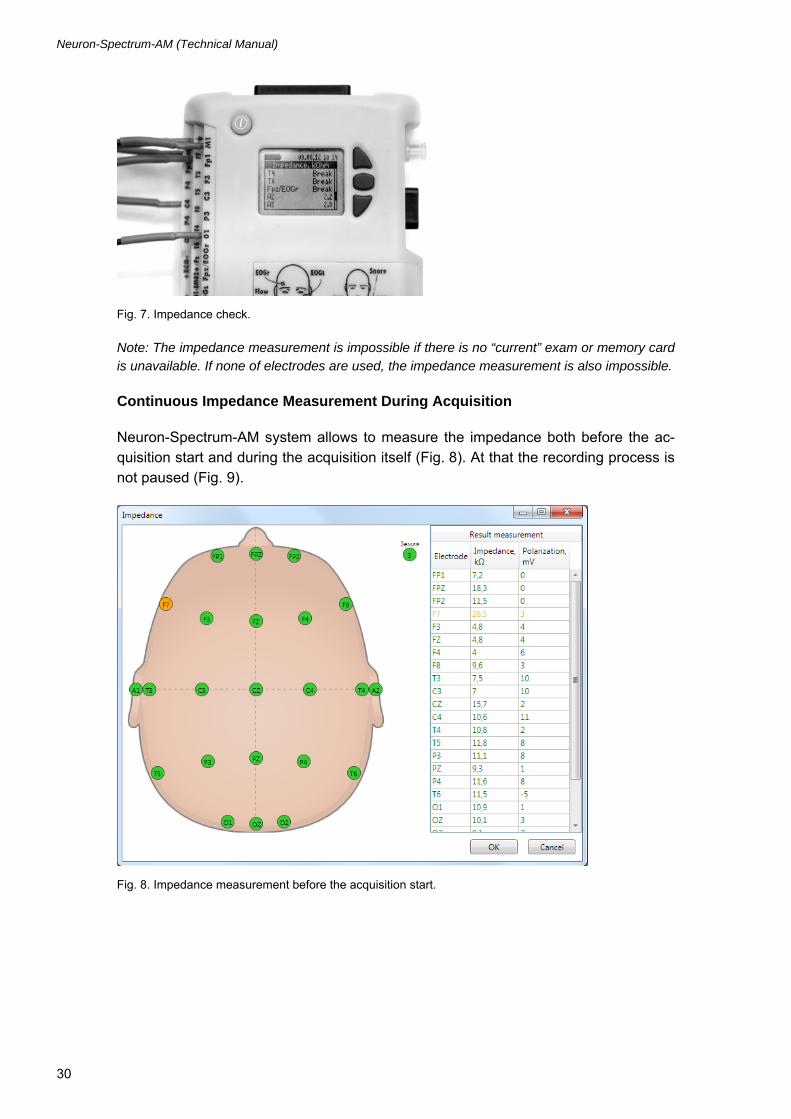
To start the electrode impedance measurement choose [Check impedance] item in the [Main menu] menu of electronic unit. The impedance measurement dialog will be displayed on the screen. This dialog contains the list of electrodes to be used in the “current” exam. The left column contains the electrode names. The right column contains impedance values in kΩ or [Breakdown] cable breakdown indication (Fig. 7). The list of impedance values is sorted in descending order. If the list is longer then the monitor height then use [Up] and [Down] buttons to navigate between the list parts. Observe the scroll bar at the right side of the display to identify the cur-rently displayed part of the list. To finish the impedance measurement, press [OK] button.
Neuron-Spectrum-AM (Technical Manual)
30
Fig. 7. Impedance check.
Note: The impedance measurement is impossible if there is no “current” exam or memory card is unavailable. If none of electrodes are used, the impedance measurement is also impossible.
Continuous Impedance Measurement During Acquisition
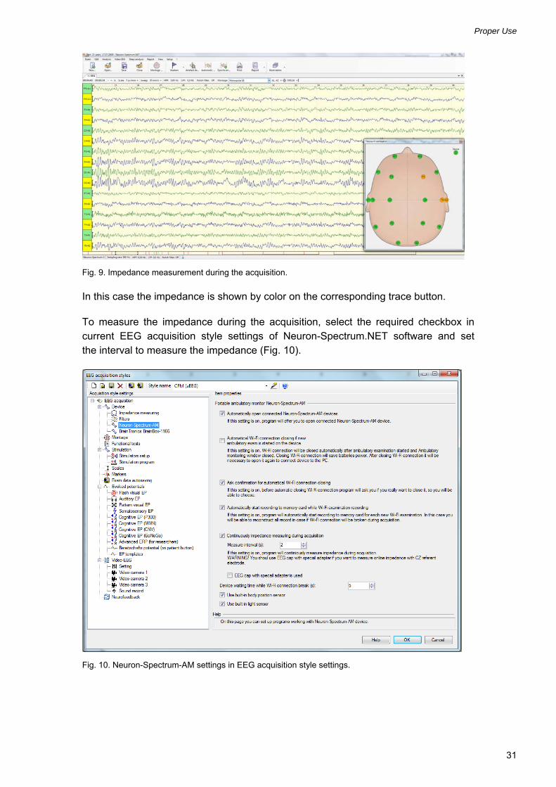
Neuron-Spectrum-AM system allows to measure the impedance both before the ac-quisition start and during the acquisition itself (Fig. 8). At that the recording process is not paused (Fig. 9).
Fig. 8. Impedance measurement before the acquisition start.
Proper Use
31
Fig. 9. Impedance measurement during the acquisition.
In this case the impedance is shown by color on the corresponding trace button.
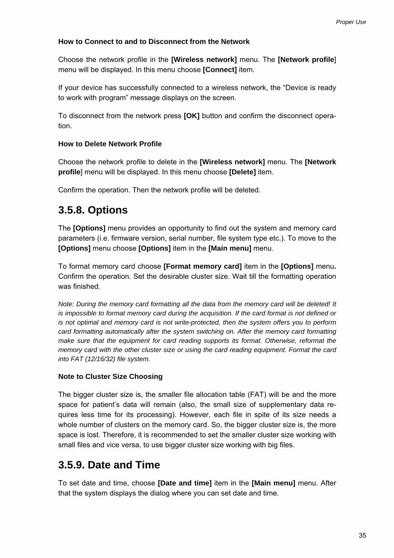
To measure the impedance during the acquisition, select the required checkbox in current EEG acquisition style settings of Neuron-Spectrum.NET software and set the interval to measure the impedance (Fig. 10).
Fig. 10. Neuron-Spectrum-AM settings in EEG acquisition style settings.

Neuron-Spectrum-AM (Technical Manual)
32
Select the “Show measured impedance on trace buttons” checkbox on “Review” page of “Setup” window to see the measured impedance on trace button (Fig. 11).
Fig. 11. The exam review settings.
Besides the function of continuous impedance measurement during acquisition can be activated using “Ambulatory monitoring” window (Fig. 12).
Fig. 12. The continuous impedance measurement in “Ambulatory monitoring” window.
The continuous impedance measurement during acquisition allows to observe the electrode placement quality during the exam. This function is especially useful during long-term monitoring.

Proper Use
33
3.5.6. Record Start
To start exam recording choose [Start recording] item in the [Main menu] menu. To start the exam acquisition the “current” exam file should exist on memory card. The exam acquisition is performed with the “current” exam parameters. During the exam acquisition the blinking circle appears in the status bar. The exam is saved on the memory card. Memory card storage structure is described in Annex 2.
If the error occurs during the acquisition, it is paused automatically and blinking ex-clamation mark appears in the status bar. To observe the reason and the time of ac-quisition stop review the record statistics.
3.5.7. Wireless Network
You should configure and setup the wireless network correctly before connecting devices to it. You can find more recommenda-tions in Annex 2.
To connect to a wireless network go to [Wireless network] menu, choosing [Wire-less network] item in the [Main menu] menu. The [Wireless network] menu con-tains the list of network profiles. Each profile can be used to save network parameters. The name of each profile contains the list of the main network parameters in the fol-lowing order:
- SSID wireless network name (if the name is longer than 10 symbols, first 7 symbols, followed by ellipsis are displayed);
- Ad hoc network marker;
- encryption system (WEP, WPA, WPA2), if encryption is used;
- IP address and subnet mask if these values were set manually (example: 192.168.0.10/16).
The preset profile can be used for wireless network connection. If the profile is not set, the menu items has [Add profile] name.
How to Add Wireless Network Profile
To add a new profile choose [Add profile] item in the [Wireless network] menu. The [New profile] menu will be displayed.
There are three ways of network parameters adjustment:
- perform network search, then choose network and enter missing parameters;
- enter all the parameters manually;
- load network parameters from the memory card.

Neuron-Spectrum-AM (Technical Manual)
34
How to Perform Network Search
To perform network search choose [Network search] item in the [New profile] menu. If at least one network was found by the system, it displays the [Found networks] menu. This menu contains names of all found networks. The name of each profile contains the list of the main network parameters in the following order:
- SSID wireless network name (if the name is longer than 10 symbols, first 7 symbols, followed by ellipsis are displayed);
- Ad hoc network marker;
- encryption system (WEP, WPA, WPA2), if encryption is used;
- list of used channel numbers.
Choose the appropriate network. If the chosen network uses encryption, enter the au-thentication method, safety key and possibly user name. If the network does not use DHCP server, set IP address and subnet mask manually.
Note: You can cancel the profile creation anytime choosing [Cancel] item.
How to Enter All the Network Parameters Manually
To enter all the network parameters manually choose [Create manually] item in the [New profile] menu. Then enter all network parameters sequentially.
Note: You can cancel the profile anytime creation choosing [Cancel] item.
How to Load Network Parameters from the Memory Card
To load network parameters from the memory card choose [Load from memory card] item in the [New profile] menu.
Note: It is impossible to load network parameters from the memory card during the acquisition. It is necessary to create file using Neuron-Spectrum.NET software and write it to the memory card beforehand.
How to Review and/or to Edit Network Profile Parameters
Choose the network profile in the [Wireless network] menu. The [Network profile] menu will be displayed.
To review and/or to edit the network name choose [Network name (SSID)] item in the [Network profile] menu. In the dialog that appears you can edit the network name.
To review and/or to edit the safety mode and parameters choose [Mode and safety] item in the [Network profile] menu.
To review and/or to edit the IP addressing parameters choose [IP address] item in the [Network profile] menu.
Proper Use
35
How to Connect to and to Disconnect from the Network
Choose the network profile in the [Wireless network] menu. The [Network profile] menu will be displayed. In this menu choose [Connect] item.
If your device has successfully connected to a wireless network, the “Device is ready to work with program” message displays on the screen.
To disconnect from the network press [OK] button and confirm the disconnect opera-tion.
How to Delete Network Profile
Choose the network profile to delete in the [Wireless network] menu. The [Network profile] menu will be displayed. In this menu choose [Delete] item.
Confirm the operation. Then the network profile will be deleted.
3.5.8. Options
The [Options] menu provides an opportunity to find out the system and memory card parameters (i.e. firmware version, serial number, file system type etc.). To move to the [Options] menu choose [Options] item in the [Main menu] menu.
To format memory card choose [Format memory card] item in the [Options] menu. Confirm the operation. Set the desirable cluster size. Wait till the formatting operation was finished.
Note: During the memory card formatting all the data from the memory card will be deleted! It is impossible to format memory card during the acquisition. If the card format is not defined or is not optimal and memory card is not write-protected, then the system offers you to perform card formatting automatically after the system switching on. After the memory card formatting make sure that the equipment for card reading supports its format. Otherwise, reformat the memory card with the other cluster size or using the card reading equipment. Format the card into FAT (12/16/32) file system.
Note to Cluster Size Choosing
The bigger cluster size is, the smaller file allocation table (FAT) will be and the more space for patient’s data will remain (also, the small size of supplementary data re-quires less time for its processing). However, each file in spite of its size needs a whole number of clusters on the memory card. So, the bigger cluster size is, the more space is lost. Therefore, it is recommended to set the smaller cluster size working with small files and vice versa, to use bigger cluster size working with big files.
3.5.9. Date and Time
To set date and time, choose [Date and time] item in the [Main menu] menu. After that the system displays the dialog where you can set date and time.

Neuron-Spectrum-AM (Technical Manual)
36
Note: It is impossible to change date and time during the acquisition (the corresponding menu item is unavailable). If date and time are not set, the system asks you to set them when the unit is switching on.
3.5.10. Language
To set the language choose [Language (language)] item in the [Main menu] menu. In the dialog that appears choose the appropriate language from the list of available languages.
Note: If unknown for you language is set, you can find [Language (language)] item by the word “language” in brackets irrespective of the current language. If language is not set, the dialog to choose language displays automatically when the unit is switching on.
3.6. Troubleshooting The list of some possible troubles and the ways of their removal is given in Table 7.
Table 7. Possible Troubles and the Ways of their Removal
Trouble symptom Cause Way of Removal
The indicators on the PC front panel do not glow at PC switching on.
Incorrect PC connection to the mains.
Check the PC connection accuracy to the mains.
PC operating system load is not carried out properly.
Faultiness of PC hardware or software.
Make PC reload. In case the trouble was not removed, address to PC firm-supplier.
Neuron-Spectrum.NET software doesn’t start.
Digital system software is not installed or is installed incorrectly.
Check whether the digital system software is set up. Reinstall digital system software using distribution disk.
The error occurs when you start the monitoring from Neuron-Spectrum.NET.
1. Local network interface parameters on the PC are set up incorrectly. 2. Wireless connection profile parameters are incompatible with wireless network. 3. The wrong profile was set when connecting to wireless network. 4. Wireless network equipment is incompatible with the electronic unit.
1. Check the correctness of PC wireless interface settings. Consult the specialist if it is necessary. 2. Consult wireless network administrator to receive the information on connection parameters required. 3. Set the appropriate profile when connecting to wireless network. 4. Replace wireless equipment with the analogous of another model or produced by another manufacturer.
During the monitoring, fades and fragment missing are observed.
1. The network is overloaded. 2. Radio propagation from electronic unit to wireless network equipment is impeded because of obstacles or long distance.
1. Take measures to lower the network loading. Consult the network administrator. 2. Remove possible obstacles for radio propagation. Decrease the distance between electronic unit and wireless network equipment.
The message “Database connection error” can appear on the display when you start the program.
1. The directory with patient exam files was renamed or replaced. 2. The directory with patient exam files is inaccessible.
1. Check the connection to local network. Make sure that the computer with patient file directory is connected to local network and switched on. 2. Restore the name and the directory placement.
The exam report can’t be created or printed.
1. The printer is not set up. 2. The printer is not connected to PC or out of order.
1. Set up the printer using Windows control panel. 2. Check the printer connection and its working order.

Servicing
37
Table 7. Continued
Trouble symptom Cause Way of Removal
After proper setting of EEG electrode, the impedance value is 1000 kΩ.
Derivation cable breaks. Replace the derivation cable.
EEG traces recorded in one hemisphere channel are not displayed adequately.
1. Problems with reference electrode (ear electrode during monopolar recording with ear electrode reference). 2. Problems with the electronic unit.
1. Check the quality of electrode setting by impedance measurement. 2. Change places of the reference electrode cables (A1 and A2). If the problem is repeated in the other hemisphere that means the electrode is out of operation. Replace it. 3. If the problem was not removed, the electronic unit is out of operation. Consult Neurosoft Company.
EEG traces recorded in one of the channels are not displayed adequately.
1. The derivation cable is faulty. 2. Problems with electronic unit.
1. Check the quality of electrode setting by impedance measurement. 2. Replace the electrode. 3. Consult Neurosoft Company.
The indicator of SpO2 channel in Neuron-Spectrum.NET software highlights red.
The SpO2 sensor is faulty or the cable is broken.
1. Check the sensor connection to the electronic unit. 2. If the problem still remains, address to Neurosoft Company.
3.7. Actions in Emergency
De-energize the system completely in case of electrical insulation disturbance of any component included in the system set which causes the emergency (fire, mechanical failure, flood, medical staff evacuation) and threat of electrical shock of patient or staff.
4. Servicing
4.1. General Requirements
Safety measures when servicing conforms to the ones described in the chap-ter 3 “Proper Use”.
Qualification requirements to medical staff are listed in chapter 2.1 “Requirements to the Personnel Conducting Mounting and Installation”.
Servicing of the bought articles included in the digital system is conducted according to user and technical manuals or typical rules.
Use the information given in chapter 3.6 “Troubleshooting” when you detect the trou-bles. If the trouble can’t be eliminated using digital system control units or by restart, it should be switched off and checked by a specialist.
The system should be serviced while the operation on the device and also maintained regularly. The volume of technical servicing is indicated in chapter 4.4 “Conservation”.

Neuron-Spectrum-AM (Technical Manual)
38
The delivery set check is done by conformity to the device packing report.
4.2. Maintenance Service
System servicing in the process of operation includes the external examination, check of connectors and cables, removal of contaminations from the units’ surface using wet fabric, battery recharging and replacement.
To support the firmware in actual state during the operation update system firmware using the instructions given in the chapter 4.3 of the present manual.
4.3. Firmware Update
To update the system firmware, perform the following steps:
1. Receive file with the new firmware version;
2. Save this file to the memory card root directory under the name "FIRMWARE" (all capital letter are obligatory!);
3. Insert the memory card and batteries into the unit battery compartment;
4. Switch on the unit using [On] button and holding [Down] button pressed;
6. Wait until the message with the firmware update statement displays on the screen;
7. Release [Down] button;
8. Press [Ok] button to confirm your wish to update the firmware;
9. Wait until the unit finishes the updating;
10. Confirm that you read the message about successful updating or about an error;
11. Confirm the unit shutting down;
12. If an error occurred you should eliminate its cause and try to update the firmware again.
This operation can result in device breakdown and should be performed by qualified staff!
4.4. Conservation
The system components including accessories and operational documentation should be packed in separate plastic sachets and then placed in a manufacturer package.
Current Repair
39
5. Current Repair
5.1. General Requirements
The system repair requires special training of technical staff, special equipment and service software which you can receive from the manufacturer or the representative of the company. The repair connected with the electronic unit opening is prohibited. The repair connected with electronic unit opening is prohibited.
If personal computer or other components providing wireless data transfer have failed, you can replace them with the analogous ones.
The current repair of the system includes the repair of some component parts and ca-bles. It is prohibited to repair the component parts when connecting to electronic unit or other units in order to avoid accidents and system irreversible damage. Switch off all system units when conducting current repair.
5.2. Repair of EEG Cables, ECG Cables and Adapters
The cables are examined externally, and the circuit is checked for short circuit or break. Shielded cables are also checked for short circuit between screen and cable, and between cables. In case the cable is broken or grounded, it is necessary to re-place or cut if the cable length is sufficient.
5.3. Breath Sensor Repair
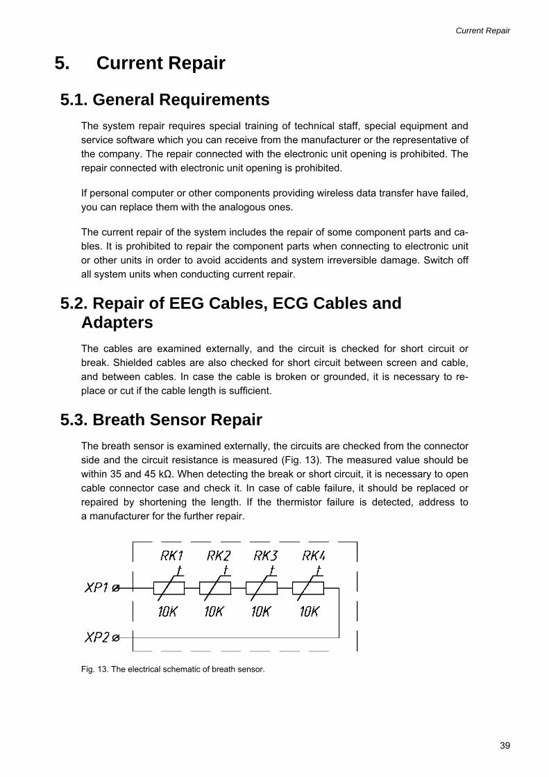
The breath sensor is examined externally, the circuits are checked from the connector side and the circuit resistance is measured (Fig. 13). The measured value should be within 35 and 45 kΩ. When detecting the break or short circuit, it is necessary to open cable connector case and check it. In case of cable failure, it should be replaced or repaired by shortening the length. If the thermistor failure is detected, address to a manufacturer for the further repair.
Fig. 13. The electrical schematic of breath sensor.

Neuron-Spectrum-AM (Technical Manual)
40
5.4. Electrode Cap Repair
The electrode cap is examined externally for cables failure detection. The cables are checked for the break between electrodes and connector pins (Fig. 14). The elec-trodes of the cap should be lubricated by the electrode conducting gel. If the cable break is detected, it should be replaced or repaired by shortening the length.
Fig. 14. The electrical schematic of electrode cap.
6. Packing and Transportation
The package should conform to the accepted one when manufacturing and delivering. In case the factory package is damaged, but the long-term system storage and trans-portation is expected, respect the following recommendations:
The system with operational documentation should be packed in plastic sachets and cardboard boxes.
The cardboard boxes should be covered by the paper tape or pressure sensitive adhesive tape.
The systems can be transported by all kinds of covered carries (except non-heated airplane pods) according to rules of goods transportation for each mode of transport at temperature varying from -50° up to +50° C.

Utilization
41
7. Utilization
The device utilization is performed according to the current legislation of the area where the equipment is used. Special requirements to device utilization are not pro-vided by the manufacturer.
8. Delivery Set and Package Data
Neuron-Spectrum-AM ambulatory EEG and PSG system with
serial number _____________________,
is collected and packed according to TC 9441-053-13218158-2012.
Package report number _______________________
Package report date _______________________
The detailed information about the delivery set is described in the package report which is an integral part of the present document and should be kept along with it.
9. Acceptance Certificate
The system corresponds to TC 9441-053-13218158-2012 and is ready for operation.
DC representative ___________________ signature
10. Delivery Certificate
The system is delivered to a customer __________________________________ date
System was handed _______________________
signature
System was accepted _____________________ signature

Neuron-Spectrum-AM (Technical Manual)
42
11. Storage Data
The system should be stored in the manufacturer package in an enclosed room at
from +5 up to +40С and 80% maximum relative humidity (measured at 25С tem-
perature). The room air should be free from any dust, acid vapors, alkali vapors, cor-rosive gases and other injurious admixtures which can cause the corrosion.
The systems should be stored on the shelves not more than in four lines.
Information about the system storage before and in the process of operation is regis-tered in Table 8.
Table 8. Storage Data
Date of
beginning of storage
end of storage
Storage conditions Position, name and signature of
person responsible for
storage

Warranty
43
12. Warranty
12.1 The manufacturer guarantees the system quality conformance to TC 9441-053-13218158-2012 requirements if the rules of operation, storage, transportation and mounting prescribed in the operational documentation are observed.
12.2 Warranty period is 24 months from the delivery date to the customer (chapter 10).
The warranty period of components exposed to wear (cables) is 30 days.
There is no warranty for consumables (gel, paste and disposable electrodes).
The warranty period can be prolonged for the period from reclamation submission up to repair completion (chapters 13, 14).
12.3 The operation of guarantee commitment is stopped if:
the rules of operation, storage, transportation and mounting prescribed in the operational documentation are not observed;
the warranty period is expired;
a user brakes the seal without permission of the manufacturer.
12.4 The manufacturer is obliged to repair the equipment in case of breakdown during the warranty period free of charge. The repair is carried out in the service center of Neu-rosoft Company (5, Voronin str., Ivanovo, 153032, Russia) only if this registration certifi-cate is provided.
You can also contact SAS Neuromed Company, Authorized European Representa-tive
of Neurosoft Company (Mr. Pierre Scholl) by the following address:
Chemin du tomple
84330 Le Barroux, France
Phone: +490-650-470, +622-748-384
Fax: +490-650-470
E-mail: [email protected]

Neuron-Spectrum-AM (Technical Manual)
44
13. Reclamation Data
13.1 In case of system breakdown or faultiness in the period of warranty and also prod-uct defect detected when primary acceptance, the consumer should send written notifi-cation to Neurosoft Ltd., authorized European representative or nearest distributor. The actual list of Neurosoft Ltd. distributors is represented on the web site: http://www.neurosoft.ru/eng/useful/links.aspx. This notification should contain the follow-ing information:
the consumer’s name and the address;
the serial number of the system (see chapter 8 of the present manual or the system marking);
the copy of chapter 10 of this manual or the number and the date of the invoice or other document confirming the system purchase.
the detailed description of failures. If it is possible indicate the reasons and circum-stances preceding the fault detection (in addition it is recommended to add the test report, the exam data, photos and other materials allowing to solve the problem as soon as possible).
13.2 In case of system return to the service center for the repair or the replacement, the following rules should be observed:
it should be packed so to exclude the possibility of its damage during the transporta-tion;
the notice (see item 13.1) and the present manual must be added to the system being returned.
13.3 All the reclamations, its description and taken measures should be registered in Table 9.

Reclamation Data
45
Table 9. Reclamation Data
The date of failure or trouble
appearance
Brief description of the trouble
The date of reclamation
sending
Taken measures Note

Neuron-Spectrum-AM (Technical Manual)
46
14. Repair Data
Table 10. Repair Data
Date Position, name, signature of
person
Name and code of faulty
unit
Degree of imperfec-
tion comple-tion of repair
arrival
Name of repair works
carried out the repair
accepted after the
repair

Annex 1. Electromagnetic Emissions and Immunity
47
Annex 1. Electromagnetic Emissions and Immunity
Guidance and manufacturer’s declaration – electromagnetic emissions
The system is intended for use in the electromagnetic environment specified below. The customer or the user of the system should assure that it is used in such an environment.
Emissions test Compliance Electromagnetic environment — guidance
RF emissions CISPR 11
Group 1 The system uses RF energy only for its internal function. Therefore, its RF emissions are very low and not likely to cause any interference in nearby electronic equipment.
RF emissions CISPR 11
Class В
Harmonic emissions IEC 61000-3-2
Not applicable
Voltage fluctuations' flicker emissions IEC 61000-3-3
Not applicable
The system is suitable for use in all establishments, including domestic establishments and those directly connected to the public low-voltage power supply network that supplies buildings used for domestic purposes.

Neuron-Spectrum-AM (Technical Manual)
48
Guidance and manufacturer’s declaration – electromagnetic immunity
The digital system is intended for use in the electromagnetic environment specified below. The customer or the user of the digital system should assure that it is used in such an environment.
Immunity test IEC 60601 test level Compliance level
Electromagnetic environment -guidance
±6 kV − contact ±6 kV Electrostatic discharge (ESD) IEC 61000-4-2
±8 kV − air ±8 kV
Floors should be wood, concrete or ceramic tile. If floors are covered with synthetic material, the relative humidity should be at least 30%.
±2 kV − for power supply lines
Not applicable Electrical fast transient/burst IEC 61000-4-4
±1 kV − for input/output lines
Not applicable
Mains power quality should be that of a typical commercial or
hospital environment.
±1 kV differential mode
Not applicable Surge IEC 61000-4-5
±2 kV common mode Not applicable
Mains power quality should be that of typical commercial or hospital environment.
<5% UT (>95% dip in UT) for
0,5 and 1 cycle
Not applicable
40% UT (60% dip in UT) for 5 cycles
Not applicable
70% UT (30% dip in UT) for 25 cycles
Not applicable
120% UT (20% dip in UT) for 25 cycles
Not applicable
Voltage dips, short interruptions and voltage variations on power supply input lines IEC 61000-4-11
<5% UT (>95% dip in UT) for 5
s
Not applicable
Mains power quality should be that of a typical commercial or hospital environment. If the user of the digital system requires continued operation during power mains interruptions, it is recommended that the digital system be powered from an uninterruptible power supply or a battery.
Power frequency magnetic field IEC 61000-4-8
3 A/m 3 A/m Power frequency magnetic fields should be that of a typical commercial or hospital environment.
Note: UT – is the a.c. mains voltage prior to application of the test level.

Annex 1. Electromagnetic Emissions and Immunity
49
Guidance and manufacturer’s declaration – electromagnetic immunity
The digital system is intended for use in the electromagnetic environment specified below. The customer or the user of the digital system should assure that it is used in such an environment.
Immunity test IEC 60601 test
level Compliance level
Electromagnetic environment -guidance
Radiated RF IEC 61000-4-3
3 V/m 80 MHz to 2.5 GHz
3 V/m
Portable and mobile RF communications equipment should be used no closer to any part of the system, including cables, than the recommended separation distance calculated from the equation applicable to the frequency of the transmitter:
Pd 17.1 (80 MHz to 800 MHz);
Pd 33.2 (800 MHz to 2.5 GHz). Field strengths from fixed RF transmitters, as determined by an electromagnetic site survey1), should be less than the compliance level in each frequency range2). Interference may occur in the vicinity of equipment marked with the following symbol:
1) Field strengths from fixed transmitters, such as base stations for radio (cellular/cordless) telephones and land mobile radios, amateur radio, AM and FM radio broadcast and TV broadcast cannot be predicted theoretically with accuracy. To assess the electromagnetic environment due to fixed RF transmitters, an electromagnetic site survey should be considered. If the measured field strength in the location in which the digital system is used exceeds the applicable RF compliance level above, the digital system should be observed to verify normal operation. If abnormal performance is observed, additional measures may be necessary, such as re-orienting or relocating the digital system. 2) Over the frequency range 150 kHz to 80 MHz, field strengths should be less than 3 V/m. Notes: 1. At 80 MHz and 800 MHz, the higher frequency range applies. 2. These guidelines may not apply in all situations. Electromagnetic propagation is affected by absorption and reflection from structures, objects and people.

Neuron-Spectrum-AM (Technical Manual)
50
Recommended separation distances between portable and mobile RF communications equipment and system
The system is intended for use in an electromagnetic environment in which radiated RF disturbances are controlled. The customer or the user of the system can help prevent electromagnetic interference by maintaining a minimum distance between portable and mobile RF communications equipment (transmitters) and the system as recommended below, according to the maximum output power of the communications equipment.
Separation distance according to frequency of transmitter, m
Rated maximum output power of transmitter, W
150 kHz up to 80 MHz outside ISM bands
Pd 17.1
80 MHz to 800 MHz
Pd 17.1
800 MHz to 2.5 GHz
Pd 23.2
0.01 0.117 0.117 0.233
0.1 0.369 0.369 0.738
1 1.167 1.167 2.333
10 3.689 3.689 7.379
100 11.667 11.667 23.333
Notes: 1. At 80 MHz and 800 MHz, the separation distance for the higher frequency range applies. 2. These guidelines may not apply in all situations. Electromagnetic propagation is affected by absorption and reflection from structures, objects and people. 3. For transmitters rated at a maximum output power not listed above, the recommended separation distance
d in meters (m) can be determined using the equation applicable to the frequency of the transmitter, where
Р is the maximum output power rating of the transmitter in watts (W) according to the transmitter manufacturer.

Annex 2. Description, Configuration and Setup of Wireless Networks
51
Annex 2. Description, Configuration and Setup of Wireless Networks
Electronic unit contains the Wi-Fi adapter to ensure the real-time monitoring of signals which arrive at the device inputs. The Wi-Fi adapter is designed to work in 2.4 GHz Wi-Fi band. The 2.4 GHz Wi-Fi band is divided into 13 channels. The spectrum of transmitting signal overlaps with 3 adjacent channels of higher and lower frequencies. Any two channel numbers that differ by five or more do not overlap. You should take it into account when setting working channels of nearby devices. It can help you to ex-clude completely the mutual interference. Channels 1, 6, and 11 are non-overlapping. You should set up the neighboring access points to these channels to avoid mutual in-terference in the point in space where simultaneous signal reception is possible.
The electronic unit firmware was developed taking into account the necessity to sup-port two basic modes of operation: ad hoc and infrastructure.
Ad hoc mode implies direct logical networking without needing any additional equip-ment. Some notebook PCs have Wi-Fi adapters which do not support ad hoc connec-tion.
In the case of wireless networking in infrastructure (managed) mode you are connect-ing your devices using a central device, namely a wireless access point.
Access point retransmits packets from wireless network to wired network and vice versa to ensure the access to wired network devices. The access point has RG45 port to connect to wired network switch. For home use access point can be integrated with cable modem and switch in one case. This unit can work as boundary router and switch, DHCP server, and often is used as media server.
You can add several access points in order to extend the coverage of wireless net-work located in different places. The optimum installation location for each access point should be properly planned. Reception areas should overlap slightly. It is made to let the device to inform one access point about disconnection and to connect to the other one. The device chooses the next access point by received signal strength. Ac-cess point should transmit a beacon – special signal identifying the presence of an access point – to make this function work.
Work of Neuron-Spectrum-AM in Ad hoc Mode
This mode should be used if there are no infrastructure networks or it is impossible to connect to them.
To create wireless network in Windows 7 press on “Add” button in wireless network wizard which is available from Manage wireless networks that use control panel (Fig. 15).

Neuron-Spectrum-AM (Technical Manual)
52
Fig. 15
After that click on the option called “Create an ad hoc network” (Fig. 16).
Fig. 16

Annex 2. Description, Configuration and Setup of Wireless Networks
53
The window that appears next requires you to give a network name, security key and the security type (WPA2-Personal is recommended) (Fig. 17).
Fig. 17
After the network creation open Network connection manager control panel (Fig. 18).
Fig. 18

Neuron-Spectrum-AM (Technical Manual)
54
Open dialog with wireless network adapter properties using this panel (Fig. 19).
Fig. 19
Open “Internet protocol version 4 (TCP/IPv4)” properties dialog (Fig. 20).
Fig. 20
The “General” tab requires you to give the PC IP address and subnet mask. You should specify an IP address within a range from 192.168.0.1 to 192.168.255.254 and

Annex 2. Description, Configuration and Setup of Wireless Networks
55
standard subnet mask 255.255.0.0 (as an example in Fig. 20 an IP address is 192.168.11.23 and subnet mask is 255.255.255.0).
The software will perform settings only if you use it to set up wireless connection.
To connect the device to the created network, first perform wireless network search using main menu. Then choose the created network from the list of networks found, specify security type and security key. They should match with security type and secu-rity key specified at the stage of wireless network creation. Specify IPv4 address manually. It should differ from the PC IP address, but belong to the same subnet. Subnet mask should match with the subnet mask specified at the stage of wireless network creation. You can find the detailed description of connection process in chap-ter 3.5.7 “Wireless Network”.
It should be noted that there are several disadvantages of using ad hoc mode:
1. Standard Windows 7 controls do not allow user to choose frequency channel. This means that there is no possibility to avoid interference from other infrastruc-ture and ad hoc networks.
2. Windows versions for private use do not have software to set network parameters automatically (DHCP server software). In this case it is necessary to enter all the parameters manually.
3. Wireless adapters of old PC models do not allow to create ad hoc networks.
4. Sometimes it is necessary to find and install new drivers for wireless network adapter because some manufacturers do not support its products.
Work of Neuron-Spectrum-AM in Infrastructure Mode
Infrastructure mode is much more expensive than ad hoc mode to implement, but it al-lows increasing throughput, and also infrastructure mode management is much easier than ad hoc mode management.
There are following configurations of infrastructure networks according to degree of complexity:
1. The network consisting of one access point and several wireless devices.
This configuration is the simplest one. There is no wired segment in this type of net-work. You should connect PC to access point using cable in order to set up network configuration. Use web-interface or special utility to specify access point and network parameters (network name, authentification method, encryption type, access key (password), used frequency channel, maximum data transmission rate (according to b/g/n standard)). Switch on the DHCP server on the access point to send automati-cally IP address and subnet mask to connecting devices. As soon as you have fin-ished with this configuration, your network is ready to use. In such networks access point retransmits packets from one device to other.

Neuron-Spectrum-AM (Technical Manual)
56
2. The network consisting of one access point and wired network segment.
Physical and logical structure of such network is given in Fig. 21.
Fig. 21
Networks which contain cable or DSL router have the same logical structure. In this case access point is integrated with boundary router and Ethernet switch in one case and has the same IP address.
In such networks boundary router perform the function of DHCP server.
In such networks you should use wired connection to PC for successful data transmit-ting. The loading of wireless channel decreases in this case.

Annex 2. Description, Configuration and Setup of Wireless Networks
57
3. The network consisting of several access points and boundary router con-nected by wired segment.
Physical and logical structure of such network is shown in Fig. 22.
Fig. 22
Wireless Network Planning and Installing
To ensure the monitoring of the obtained signals in real-time mode, the system uses the built-in wireless adapter that complies with wireless IEEE802.11b/g/n standards. When planning the system it is recommended to think of the way of electronic unit in-tegration to the existing WLAN. If the WLAN infrastructure is missing, it should be de-signed correctly. Involve the specialists to mount and install the WLAN objects. If you want to mount and set up the WLAN by yourself, avoid the following mistakes that may result in monitoring failure:
1. Some adjacent base stations of one or different WLAN may use one and the same frequency channel. At that mutual interferences emitted by radio equipment of different networks are possible. It may decrease the data rate and sometimes may prevent from data transfer. It is recommended to select the fre-quency channels to ensure the interval between them (at least 5). For example, three WLAN can function successfully at the same territory if 1, 6, 11 channels are specified for these base stations.
2. By default the access points operate in open mode without data encryption and password. In this case other radio equipment may get an access to your WLAN and use the network capacity in its purposes, prevent from data transfer from ac-quisition units. To avoid it, specify WPA2 encryption method for your stations and set the reliable password to protect from violators.

Neuron-Spectrum-AM (Technical Manual)
58
3. During a study a patient with acquisition unit may walk along quite large area. In some points the stable connection between patient’s unit and base station is not ensured. In these cases the connection depends on patient’s moving. It is rec-ommended either to limit an area to walk or to select properly the place to install WLAN base station to ensure the required coverage. The installation place is se-lected using the special measuring instruments or, if you don’t have any, experi-mentally. In special cases when large coverage is required, you can implement WLAN with several base stations.
4. If you use several acquisition units simultaneously, make sure that all of them are in base station coverage area. When a patient moves away from base station, the connection speed with the unit slows down and the data rate decreases. It may also impact the connection stability with other acquisition units fixed on other patients even if they are in coverage area.
Recommendations on Base Station Arrangement and Set up of Non-intersecting Channels (for Equipment that Complies with 802.11b/g Standards)
Fig. 23. Recommended network configuration.
To ensure the correct operation of Neuron-Spectrum-AM system it is recommended to observe the following rules:
1. Arrange not more than four acquisition units in one base station coverage area. The coverage area is the one with stable connection in monitoring mode. It is shown by a circle in Fig. 23. In fact the coverage area depends on the line-of-sight conditions (presence of walls, partition walls, etc), RF interference (micro-wave ovens, security systems, etc.) and environment conditions.
Annex 3. Memory Card File Storage Structure
59
2. When a patient is to be moved, make sure that the network area coverage is enough. The optimal WLAN network requires overlaps of 20 percent (dashed area in Fig. 23).
3. A patient should always stay in network coverage area. Otherwise it may impact the operation of other acquisition units.
4. The frequency channels of adjacent base stations should differ at least in 5 num-bers (for example, choose 1, 6 and 11 frequency channels).
5. You must use the network to monitor the signals delivered from Neuron-Spectrum-AM acquisition units to ensure the stable operation and disable access to Internet.
Annex 3. Memory Card File Storage Structure
The work directory has NS\DEV_0001 name. It can contain exam subdirectories and REC_TMLP setting file to create new exams.
Each exam is saved on memory card in an individual subfolder. The subfolder name is REC_XXXX, where X is decimal number. The subfolder naming is performed in consecutive order from REC_0001 to REC_9999. So, you can save not more than 9999 exams on one memory card. To delete the exam you should delete the corre-sponding subfolder from the memory card. You can delete exams selectively. The exam with the maximum number in the subfolder name is considered to be the “cur-rent” one.
Each subfolder contains REC_TMLP file with the exam parameters. An exam data are saved in the files wits DAT_XXXX names, where X is decimal number. The exam file naming is performed in consecutive order from DAT_0001 to DAT_9999. So, you can save not more than 9999 files in each exam folder. On each exam recording start, a new file is created. If the exam recording is performed uninterruptedly, the exam data are saved in files of not more than 1 GB size.


![002 CBB_T01_E2 Principle and Implementation of CDMA Spread Spectrum-27 [Compatibility Mode]](https://static.fdocuments.us/doc/165x107/577d27591a28ab4e1ea3b08e/002-cbbt01e2-principle-and-implementation-of-cdma-spread-spectrum-27-compatibility.jpg)