
Installation, Operation and Pitco Frialator
26
Pitco Frialator Literature # L20-056 R4 (06/11) R APPROVED Installation, Operation and Maintenance Manual for Fryer Model Numbers 7,12,14,14R & 18 Gas Fryers With Options and (F) Built-In and UFM (Spacefighter) Filter Systems R R
Transcript of Installation, Operation and Pitco Frialator

Pitc
o Fr
iala
tor
Literature # L20-056 R4 (06/11)
R APPROVED
Installation, Operation and Maintenance Manual
forFryer Model Numbers
7,12,14,14R & 18Gas Fryers With Options
and(F) Built-In and UFM (Spacefighter)
Filter Systems
R R
ORIGINAL EQUIPMENT LIMITED WARRANTYGeneral Warranty
Pitco Frialator, Inc. warrants to the original user of its commercial cooking appliances and related equipment that said appliances and related equipmentwill be free from defects in material and workmanship under normal use for a period of one (1) year from the date of installation, with appropriate documen-tation, to a maximum of fifteen (15) months from the date of manufacture, subject to the following additions, exceptions, exclusions and limitations.
What is covered.This warranty is limited to the repair or replacement at the Company’s option, without charge, any part found to be defective within the warranty period
and reasonable expenses incurred for freight and material for the installation of such part; in addition, the Company’s obligation shall be limited to reimburse-ment for normal labor on such parts.
Pitco Frialator, Inc. agrees to pay The Blodgett Corporation Authorized Service and Parts Distributor, for any labor and material required to repair orreplace, at the Company’s option, any part which may fail due to defects in material or workmanship during the above general warranty period.
Standard Fryers and CookersIn addition to the above general warranty, for its standard fryers and cookers, the Company warrants to the original user any stainless steel fry tank or
cooking vessel to be free from defects for a period of ten (10) years from the date of manufacture and any standard fry tank to be free from defects for a periodof five (5) years from the date of manufacture. Labor and freight shall be the responsibility of the user.
Economy Gas FryersIn addition to the above general warranty, for its economy gas fryers, the Company warrants to the original user any stainless steel fry tank to be free
from defects for a period of five (5) years from the date of manufacture and any standard fry tank to be free from defects for a period of three (3) years fromthe date of manufacture. Labor and freight shall be the responsibility of the user.
Limitations to Fry Tank and Cooking Vessel WarrantyAfter the expiration of the general warranty period, any additional warranty on fry tanks or cooking vessels shall only obligate the Company to repair
or replace, at its option, any fry tank or cooking vessel which it determines to be defective. Claims under this item shall be supported by a statement detailingthe defect, and the Company may require the return of the fry tank or cooking vessel claimed to be defective.
How to Keep Your Warranty in Force.€ Make sure any shipping damages reported immediately. Damages of this nature are responsibility of the carrier.€ Install the unit properly. This is the responsibility of the installer and the procedures are outlined in the manual.€ Do not install it in a home or residence.€ If it is not maintained properly. This is the responsibility of the user of the appliance and the procedures are outlined in the manual.€ Maintain it properly. This is the responsibility of the user of the appliance and the procedures are outlined in the manual.€ Adjustments, such as calibration, leveling, tightening of fasteners or plumbing or electrical connections normally associated with initial installa-
tion. These procedures are outlined in the manual.€ If it is damaged due to flood, fire or other acts of God, this is not covered under this warranty.€ Use it for what it is intended. If it is used for a purpose other than for which it was intended or designed, resulting damages are not covered under
the warranty.€ Make sure that it has the correct voltage, gas supply and/or good quality water. If a failure is due to poor water quality, harsh chemical action,
erratic voltage or gas supplies these damages are not covered under the warranty.€ Do not materially alter or modify from the condition in which it left the factory.€ Do not obliterate, remove or alter the serial number rating plate.€ Use only Genuine OEM parts from Pitco Frialator, Inc. or its Authorized Parts and Service Distributors, repairs are not covered by the warranty.€ If any other failure occurs which is not attributable to a defect in materials or workmanship, it is not covered.This warranty specifically excludes parts which wear or would be replaced under normal usage, including, but not limited to, electric lamps, fuses,
interior or exterior finishes and gaskets.Limits to the Warranty
Outside the United States of America and Canada, this warranty is limited to the replacement of parts and Pitco Frialator, Inc. will not bear any otherexpense be it labor, mileage, freight or travel.
Charges for mileage over one hundred (100) miles, travel time over two (2) hours, overtime, and holiday charges are not covered under this warranty.These charges are the responsibility of the individual or firm requesting these services.
If any oral statements have been made regarding the appliance, these statements do not constitute warranties and are not part of the contract of sale. Thislimited warranty constitutes the complete, final and exclusive statement with regard to warranties.
THIS LIMITED WARRANTY IS EXCLUSIVE AND IS IN LIEU OF ALL OTHER WARRANTIES WHETHER WRITTEN, ORAL OR IMPLIED,INCLUDING, BUT NOT LIMITED TO ANY WARRANTY OF MERCHANTABILITY OR FITNESS FOR A PARTICULAR PURPOSE OR WARRANTYAGAINST LATENT DEFECTS.
Limitations of LiabilityIn the event of a warranty or other claim, the sole obligation of Pitco Frialator, Inc. will be the repair or replacement, at the Company’s option, of the
appliance or the component part. This repair or replacement will be at the expense of Pitco Frialator, Inc. except as limited by this warranty statement. Anyrepair or replacement under this warranty does not constitute an extension in time to the original warranty. Parts covered under this warranty will be repairedor replaced, at the Company’s option, with new or functionally operative parts. The liability of Pitco Frialator, Inc. on any claim of any kind, including claimsbased on warranty, express or implied contract, negligence, strict liability or any other legal theories will be exclusively the repair or replacement of theappliance. This liability will not include, and the purchaser specifically renounces any right to recover special, incidental, consequential or other damages ofany kind, including, but not limited to, injuries to persons, damage to property, loss of profits or anticipated loss of the use of this appliance.
If any provision of this warranty is unenforceable under the law of any jurisdiction, that provision only will be inapplicable there, and the remainder ofthe warranty will remain unaffected. The maximum exclusion or limitation allowed by law will be substituted for the unenforceable provision.
How to Obtain Warranty ServiceFirst direct your claim to the Blodgett Corporation Authorized Service and Parts Distributor closest to you giving complete model, serial and code
numbers, voltage, gas type, and description of the problem. Proof of the date of installation and/or the sales slip may also be required. If this procedure failsto be satisfactory, write the National Service Manager, Pitco Frialator, Inc., P. O. Box 501, Concord, NH. 03302-0501. USA
This warranty gives you certain specific legal rights; you may have other rights which vary from state to state.

NOTICES
There are three different types of notices that you should be familiar with, a NOTICE, CAUTION, andWARNING. A NOTICE is a special note used to call attention to a particularly important point. CAU-TION is used to point out a procedure or operation which may cause equipment damage. The WARN-ING notice is the most important of the three because it warns of an operation that may cause personalinjury. Please familiarize yourself with your new cooker before operating it and heed the noticesthroughout this manual. The WARNINGS are listed below and on the following page for your reviewprior to operating the unit.
FOR YOUR SAFETY
DO NOT store or use gasoline or other flammable vapors or liquids inthe vicinity of this or any other appliance.
WARNING:
Improper installation, adjustment, alteration, service or maintenancecan cause property damage, injury or death. Read the installation,
operating and maintenance instructions thoroughly before installing orservicing this equipment.
TO THE PURCHASER
POST IN A PROMINENT LOCATION INSTRUCTIONS TO BE FOL-LOWED IN THE EVENT THAT AN OPERATOR SMELLS GAS.
OBTAIN THIS INFORMATION FROM YOUR LOCAL GAS SUP-PLIER.
THIS MANUAL MUST BE RETAINED FOR FUTURE REFERENCE
TO THE PURCHASER, OWNER AND STORE MANAGERPlease review these warnings prior to posting them in a prominent location for reference.
L20-303 Rev 1. (05/11)2
WARNINGDO NOT store or use gasoline or other flammablevapors and liquids in the vicinity of this or any otherappliance.
WARNINGImproper installation, alteration, service ormaintenance can cause property damage, injury ordeath. Read the installation, operating andmaintenance instructions thoroughly before installingor servicing this appliance.
WARNINGInstallation, maintenance and repairs should beperformed by a Pitco Authorized Service and Parts(ASAP) company technician or other qualifiedpersonnel. Installation, maintenance or repairs byunauthorized and unqualified personnel will void thewarranty.
WARNINGInstallation and all connections must be madeaccording to national and local regulations and codesin force.
WARNINGA country approved all pole circuit breaker with aminimum open contact gap of 3mm must be used forproper installation. (CE countries)
WARNINGDuring the warranty period if a customer elects to use anon-original part or modifies an original part purchasedfrom Pitco and/or its Authorized Service and Parts(ASAP) companies, this warranty will be void. Inaddition, Pitco and its affiliates will not be liable for anyclaims, damages or expenses incurred by the customerwhich arises directly or indirectly, in whole or in part,due to the installation of any modified part and/orreceived from an unauthorized service center.
WARNINGThis appliance, when installed, must be electricallygrounded in accordance with local codes, or in theabsence of local codes, with the National ElectricalCode, ANSI/NFPA 70, or the Canadian Electrical Code,CSA C22.2, as applicable.
WARNINGDO NOT alter or remove structural material on theappliance to facilitate storage or for any other reason.
WARNINGThis appliance is intended for professional use onlyand should be operated by fully trained and qualifiedpersonnel.
WARNINGDO NOT use the electrical cord as a leash to move theappliance. Series injury and appliance damage canoccur.
WARNINGIf the supplied power cord or receptacle is damaged, itmust be replaced by a Pitco Authorized Service andParts (ASAP) company technician, or a similarlyqualified person in order to avoid a hazard.
WARNINGThe power supply must be disconnected beforeservicing, maintaining or cleaning this appliance.
WARNINGThe appliance is NOT jet stream approved. DO NOTclean the appliance with a water jet.
WARNINGDO NOT attempt to move this appliance or transfer hotliquids from one container to another when the unit isat operating temperature or filled with hot liquids.Serious personal injury could result if skin comes incontact with the hot surfaces or liquids.
WARNINGDO NOT sit or stand on this appliance. The appliance’stop panel, filter pan, filter carriage, pan cover is not astep. Serious injury could result from slipping, fallingor contact with hot liquids.
WARNINGNEVER use the appliance as a step for cleaning oraccessing the ventilation hood. Serious injury couldresult from slips, trips or from contacting hot liquids.
WARNINGThe filter pan should be dry and free of water dropletsprior to use. Serious injury could result from hot steamvapors when hot oil/shortening mixes with water.
WARNINGDO NOT overfill filter pan with hot oil/shortening. Donot leave appliance unattended while draining orrefilling with oil/shortening. Over filling the appliancecan cause serious injuries and damage the appliance.
WARNINGThe contents of the crumb catch and/or filter pan ofany filter system must be emptied into a fireproofcontainer at the end of each day. Some food particlescan spontaneously combust if left soaking in certaintypes of oil or shortening.
WARNINGCompletely shut the appliance down when theoil/shortening is being drained from the appliance. Thiswill prevent the appliance from heating up during thedraining and filling process. Serious injury andappliance damage can occur.
WARNINGThis appliance is intended for indoor use only.
WARNINGDO NOT operate appliance unless all panels andaccess covers are attached correctly.
WARNINGIt is recommended that this appliance be inspected bya qualified service technician for proper performanceand operation on a yearly basis
WARNINGThis appliance is designed to operate on a specificvoltage. This information can be found on the dataplate located on the rear of the appliance
.
PKingsbury
Rectangle
PKingsbury
Rectangle

i
Table of Contents
Section Title PageChapter 1: General Information................................................................................................ 1
Which Fryer Do I Have? ................................................................................................. 1Checking Your New Fryer .............................................................................................. 1Check Your Order ........................................................................................................... 1
Chapter 2: Assembly and Leveling ........................................................................................... 2Leg/Caster Installation and Adjustment .......................................................................... 2Heat Deflector Installation .............................................................................................. 2Basket Lift Access ........................................................................................................... 3Assembling of Multi Fryer Systems ................................................................................ 3
Chapter 3: Installation ............................................................................................................... 4Installation Clearances .................................................................................................... 4Gas Connection ............................................................................................................... 4Electrical Connection ...................................................................................................... 4Ventilation and Fire Safety Systems ............................................................................... 5Initial Adjustments .......................................................................................................... 5Visual Checks.................................................................................................................. 5Burner Ignition Systems .................................................................................................. 6Main Burner Systems ...................................................................................................... 7Initial Cleaning ................................................................................................................ 7Thermostat Calibration Check ........................................................................................ 7
Chapter 2: Operating Instructions ....................................................................................... 1FILLING THE FRYER .......................................................................................................... 2-1
Filling the Fryer With Liquid Shortening ..................................................................... 2-1Filling the Fryer With Solid Shortening ....................................................................... 2-1
2.2 MELTING SOLID SHORTENING .......................................................................... 2-22.2.1 Automatic Shortening Melting ............................................................................ 2-22.2.2 Manual Shortening Melting ................................................................................. 2-22.3 OPERATING INSTRUCTIONS - WITHOUT A COMPUTER .............................. 2-32.3.1 Fryer Start-Up ...................................................................................................... 2-32.3.2 Automatic Basket Lifts (Optional) ...................................................................... 2-32.3.3 Fryer Shutdown ................................................................................................... 2-42.3.4 Power Failure ....................................................................................................... 2-42.4 OPERATING INSTRUCTIONS - WITH A COMPUTER ...................................... 2-42.4.1 Fryer Start-Up ...................................................................................................... 2-42.4.2 Product Selection ................................................................................................. 2-52.4.3 Shutdown ............................................................................................................. 2-5
ii
Table of Contents (Continued)
Section Title Page
2.4.4 Power Failure ....................................................................................................... 2-52.5 THE INTELLIFRY COMPUTER............................................................................. 2-62.5.1 Checking the Temperature functions and Cooking Times .................................. 2-72.5.2 Programming Cook Time, Shake Time and Hold Times .................................... 2-72.5.3 Programming Cooking Temperature ................................................................... 2-82.5.4 Level 2 Programming .......................................................................................... 2-82.6 THE DIGITAL CONTROL ...................................................................................... 2-92.6.1 Operating the Digital control ............................................................................... 2-92.6.2 Programming the Digital control ....................................................................... 2-102.7 SHORTENING FILTER PROCEDURES .............................................................. 2-112.7.1 General Filter Hints ........................................................................................... 2-132.7.2 Filter Procedures ................................................................................................ 2-142.7.3 Using The UFM Module As A Portable Filter .................................................. 2-162.8 DAILY CLEANING ............................................................................................... 2-16
CHAPTER 3: Owner Maintenance and Adjustments .......................................................... 3-1
3.1 FILTER MEDIA REPLACEMENT ......................................................................... 3-13.1.1 UFM Filter System .............................................................................................. 3-13.1.2 Built-In Filter System .......................................................................................... 3-43.2 WEEKLY FRYER CLEANING (BOIL OUT) ......................................................... 3-83.3 INSTALLING THE OPTIONAL FLUSH HOSE ..................................................... 3-93.4 FLUE INSPECTION ................................................................................................. 3-93.5 BASKET LIFT LUBRICATION .............................................................................. 3-93.6 TROUBLESHOOTING .......................................................................................... 3-103.6.1 Fryer Troubleshooting ....................................................................................... 3-103.6.2 Built-In Filter Troubleshooting ......................................................................... 3-123.6.3 UFM Filter Troubleshooting ............................................................................. 3-14

1
Chapter 1 - General Information
Congratulations on the purchase of your new Pitco Frialatoruniversal fryer. This unit will give you many years of reliableservice if you follow the simple operation and maintenanceprocedures in this manual. Contained in this manual are thegeneral installation, operation, and maintenance procedures forthe universal fryer Models 7, 12, 14, & 18. This informationcovers both units with built-in filters and Under Fryer Manual(UFM) filter.
WHICH FRYER DO I HAVE?
There are many models and options available for the gas fryer,each with its own model number. To find out which model youhave, look inside the door at the equipmentData Plate. This DataPlate contains the following information: Model Number, Se-rial Number, BTU Rating, Gas Type, Gas Pressure Rquirementsand Voltage Requirements.
CHECKING YOUR NEW FRYER.
Your new fryer and it's filter (where applicable) have beencarefully packed. If a UFM style filter has been shipped to youit will be packed in a separate box and strapped to the top of thefryer crate. Every effort has been made to ensure that your fryerwill be delivered to you in perfect condition. As you unpackyour new fryer, inspect each of the pieces for damage. Ifsomething is damaged, DO NOT sign the bill of lading. Contactthe shipper immediately, the shipper is only responsible for 15days after delivery. Check the packing list enclosed with yourfryer to ensure that you have received all of the parts to the fryer.If you are missing any parts, contact the DEALER from whomthe fryer was purchased. As you unpack the fryer and it'saccessories be careful to keep the weight of the fryer evenlydistributed.
CAUTIONTo prevent equipment damage, do not tilt the fryer onto anytwo of it's casters/legs or pull the unit by the flue vents.
1
9
Locate the model and serial numbers from each piece ofequipment you purchased and write them, along with the Purchseand Installation dates , in the place provided in the front of thismanual. KEEP THIS MANUAL IN A SAFE PLACE FORFUTURE REFERENCE.
CHECK YOUR ORDER
The crate containing the fryer unit will also contain the follow-ing:
2 - Fry baskets per fryer1 - Fry Basket Hanger per fryer2 - Pitco Cleaner Sample ...................................... Item # 51 - Drain Clean Out Rod ....................................... Item # 4The crate with the filter module (if applicable) also contains thefilter tools and accessories shown in picture. These items arevery important and MUST be retained for future use. A com-plete description of each component is contained in the Oil/shortening Filter Procedure Chapter.1 - Filter Crumb Catch ......................................... Item # 31 - Precoat Filter Aid ........................................... Item # 71 - Flush Hose (Optional) .................................... Item # 125 - Filter Sheets .................................................... Item # 21 - Cleaning Brush (Fryer) ................................... Item # 81 - Fryer Crumb Scoop ........................................ Item # 91 - Filter Crumb Scoop ........................................ Item # 6
Filter Tools and Accessories3 42
5 76 8
FlueVent
2
Chapter 2 - Assembly and Leveling
When you receive your fryer it is completely assembled with thepossible exception of the legs (or casters) and the heat shield. Insome cases if you have purchased a multi-fryer unit you mayneed to assemble the system.
LEG/CASTER INSTALLATION and ADJUSTMENT
Installing the legs and leveling the fryer is done with two 7/16"wrenches and a large pair of Slip Lock pliers. The legs/castersmust be installed to provide the necessary height to meetsanitation requirements and assure adequate air supply to theburners. Attach the legs/casters by performing the followingprocedure.
a. Lay the fryer on its back being careful not to damage theflue by pulling on it. Protect the outside of the fryer withcardboard or similar material when laying it down.
b. Attach each leg/caster with the four 1/4-20 x 5/8" boltssupplied with the fryer.
c. Mount the bolts from the inside of the fryer with the nut onthe outside. The nuts have lock washers attached to them,therefore it is not necessary to use lock washers.
d. When all four legs/casters are mounted, stand the unit upbeing careful not to put too much weight on any one leg/caster. Adjust the height and level the fryer by adjusting theleveling devices on the leg/caster with the water pumppliers.
e. On units with casters, move the fryer to the desired locationand lock the wheels using the locking devices on the sidesof the front wheels.
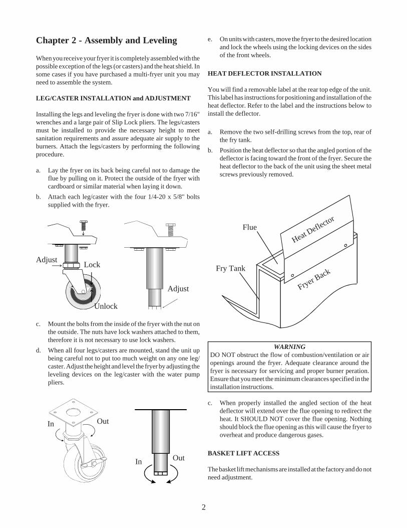
HEAT DEFLECTOR INSTALLATION
You will find a removable label at the rear top edge of the unit.This label has instructions for positioning and installation of theheat deflector. Refer to the label and the instructions below toinstall the deflector.
a. Remove the two self-drilling screws from the top, rear ofthe fry tank.
b. Position the heat deflector so that the angled portion of thedeflector is facing toward the front of the fryer. Secure theheat deflector to the back of the unit using the sheet metalscrews previously removed.
WARNINGDO NOT obstruct the flow of combustion/ventilation or airopenings around the fryer. Adequate clearance around thefryer is necessary for servicing and proper burner peration.Ensure that you meet the minimum clearances specified in theinstallation instructions.
c. When properly installed the angled section of the heatdeflector will extend over the flue opening to redirect theheat. It SHOULD NOT cover the flue opening. Nothingshould block the flue opening as this will cause the fryer tooverheat and produce dangerous gases.
BASKET LIFT ACCESS
The basket lift mechanisms are installed at the factory and do notneed adjustment.
In
In
Out
Out
Adjust
Unlock
LockAdjust
Heat Deflector
Fryer Back
Flue
Fry Tank

3
ASSEMBLY OF MULTI FRYER SYSTEMS
If you purchased a multi-fryer unit it could be shipped in morethan one piece. There are five joining strips that need to beattached in the Rear, Front, Upper Front, and under the Frontand Rear Leg/Caster Mounting Plates. To assemble the unitfollow the instructions below.
a. Unpack the units and move them close together.b. Remove the Front Panels and Burner Heat Shields from
each fryer.c. Lay the fryers on their backs using cardboard or similar
material to protect the surfaces.d. Remove the legs/casters and reattach them by placing the
Joining Plates between the leg/caster and the frame of thefryers.
e. Use the screws supplied with your system to attach theFront and Upper Front joining strips. Secure them tightly.
f. Stand the fryer system up but do not allow too much weightto be placed on any one leg/caster.
g. Attach the Rear joining strip the back of the fryer systemusing the supplied screws.
h. Connect the Filter Return Piping and the Drain Manifoldusing the supplied parts. Copy the layout from the existingfryers. Use a little cooking oil to lubriacte the Orangegaskets before forcing them over the piping.
i. Replace the Burner Heat Shields and Front Panels tocomplete the system assembly.
4
Chapter 3 - INSTALLATION
Although it is possible for you to install and set up your newfryer, it is STRONGLY recommended that you have it done byqualified professionals. The professionals that install your newfryer will know the local building codes and ensure that yourinstallation is safe.
WARNINGThe fryer must be properly restrained to prevent movement ortipping. This restraint must prevent the fryer from movementsthat would splash hot liquids on personnel. This restraint maybe any means (alcove installation, adequate ties, or batteryinstallation).
INSTALLATION CLEARANCES
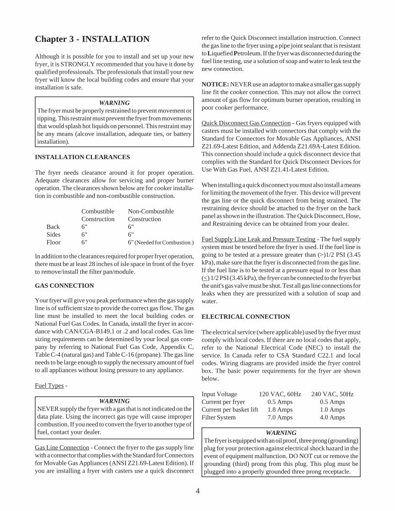
The fryer needs clearance around it for proper operation.Adequate clearances allow for servicing and proper burneroperation. The clearances shown below are for cooker installa-tion in combustible and non-combustible construction.
Combustible Non-CombustibleConstruction Construction
Back 6" 6"Sides 6" 6"Floor 6" 6" (Needed for Combustion.)
In addition to the clearances required for proper fryer operation,there must be at least 28 inches of isle space in front of the fryerto remove/install the filter pan/module.
GAS CONNECTION
Your fryer will give you peak performance when the gas supplyline is of sufficient size to provide the correct gas flow. The gasline must be installed to meet the local building codes orNational Fuel Gas Codes. In Canada, install the fryer in accor-dance with CAN/CGA-B149.1 or .2 and local codes. Gas linesizing requirements can be determined by your local gas com-pany by referring to National Fuel Gas Code, Appendix C,Table C-4 (natural gas) and Table C-16 (propane). The gas lineneeds to be large enough to supply the necessary amount of fuelto all appliances without losing pressure to any appliance.
Fuel Types -
WARNINGNEVER supply the fryer with a gas that is not indicated on thedata plate. Using the incorrect gas type will cause impropercombustion. If you need to convert the fryer to another type offuel, contact your dealer.
Gas Line Connection - Connect the fryer to the gas supply linewith a connector that complies with the Standard for Connectorsfor Movable Gas Appliances (ANSI Z21.69-Latest Edition). Ifyou are installing a fryer with casters use a quick disconnect
refer to the Quick Disconnect installation instruction. Connectthe gas line to the fryer using a pipe joint sealant that is resistantto Liquefied Petroleum. If the fryer was disconnected during thefuel line testing, use a solution of soap and water to leak test thenew connection.
NOTICE: NEVER use an adaptor to make a smaller gas supplyline fit the cooker connection. This may not allow the correctamount of gas flow for optimum burner operation, resulting inpoor cooker performance.
Quick Disconnect Gas Connection - Gas fryers equipped withcasters must be installed with connectors that comply with theStandard for Connectors for Movable Gas Appliances, ANSIZ21.69-Latest Edition, and Addenda Z21.69A-Latest Edition.This connection should include a quick disconnect device thatcomplies with the Standard for Quick Disconnect Devices forUse With Gas Fuel, ANSI Z21.41-Latest Edition.
When installing a quick disconnect you must also install a meansfor limiting the movement of the fryer. This device will preventthe gas line or the quick disconnect from being strained. Therestraining device should be attached to the fryer on the backpanel as shown in the illustration. The Quick Disconnect, Hose,and Restraining device can be obtained from your dealer.
Fuel Supply Line Leak and Pressure Testing - The fuel supplysystem must be tested before the fryer is used. If the fuel line isgoing to be tested at a pressure greater than (>)1/2 PSI (3.45kPa), make sure that the fryer is disconnected from the gas line.If the fuel line is to be tested at a pressure equal to or less than(<) 1/2 PSI (3.45 kPa), the fryer can be connected to the fryer butthe unit's gas valve must be shut. Test all gas line connections forleaks when they are pressurized with a solution of soap andwater.
ELECTRICAL CONNECTION
The electrical service (where applicable) used by the fryer mustcomply with local codes. If there are no local codes that apply,refer to the National Electrical Code (NEC) to install theservice. In Canada refer to CSA Standard C22.1 and localcodes. Wiring diagrams are provided inside the fryer controlbox. The basic power requirements for the fryer are shownbelow.
Input Voltage 120 VAC, 60Hz 240 VAC, 50HzCurrent per fryer 0.5 Amps 0.5 AmpsCurrent per basket lift 1.8 Amps 1.0 AmpsFilter System 7.0 Amps 4.0 Amps
WARNINGThe fryer is equipped with an oil proof, three prong (grounding)plug for your protection against electrical shock hazard in theevent of equipment malfunction. DO NOT cut or remove thegrounding (third) prong from this plug. This plug must beplugged into a properly grounded three prong receptacle.
5
Electrical System for Filter System - The UFM fryer has onepower supply for the fryer controls and the filter module. Whenthe fryer next to a Built In Filter has power, the filter is internallywired into the fryer. When the Fryer next to the Built-In filtersystem doesn't require power the Filter is supplied with its ownpower cord.
All fryer must be grounded in accordance with local code; if nolocal code apply, comply with NEC ANSI/NFPA No. 70-LatestEdition. It is advised that this power supply be plugged into awall receptacle that is controlled by the Hood system. This willprevent the fryer from being operated without the Hood running.The UFM filter system also has a power cord which is pluggedinto the receptacle mounted on the right hand side on the insideof the fryer.
VENTILATION and FIRE SYSTEMS
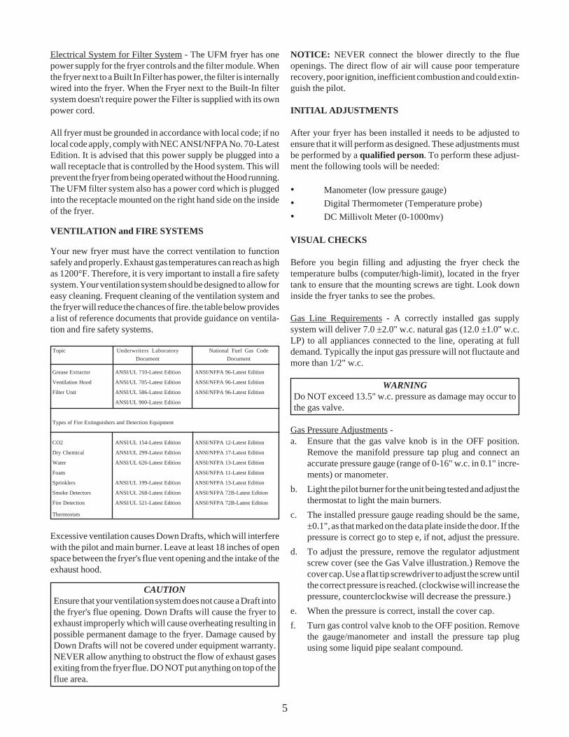
Your new fryer must have the correct ventilation to functionsafely and properly. Exhaust gas temperatures can reach as highas 1200°F. Therefore, it is very important to install a fire safetysystem. Your ventilation system should be designed to allow foreasy cleaning. Frequent cleaning of the ventilation system andthe fryer will reduce the chances of fire. the table below providesa list of reference documents that provide guidance on ventila-tion and fire safety systems.
Topic Underwriters Laboratory National Fuel Gas CodeDocument Document
Grease Extractor ANSI/UL 710-Latest Edition ANSI/NFPA 96-Latest Edition
Ventilation Hood ANSI/UL 705-Latest Edition ANSI/NFPA 96-Latest Edition
Filter Unit ANSI/UL 586-Latest Edition ANSI/NFPA 96-Latest Edition
ANSI/UL 900-Latest Edition
Types of Fire Extinguishers and Detection Equipment
CO2 ANSI/UL 154-Latest Edition ANSI/NFPA 12-Latest Edition
Dry Chemical ANSI/UL 299-Latest Edition ANSI/NFPA 17-Latest Edition
Water ANSI/UL 626-Latest Edition ANSI/NFPA 13-Latest Edition
Foam ANSI/NFPA 11-Latest Edition
Sprinklers ANSI/UL 199-Latest Edition ANSI/NFPA 13-Latest Edition
Smoke Detectors ANSI/UL 268-Latest Edition ANSI/NFPA 72B-Latest Edition
Fire Detection ANSI/UL 521-Latest Edition ANSI/NFPA 72B-Latest Edition
Thermostats
Excessive ventilation causes Down Drafts, which will interferewith the pilot and main burner. Leave at least 18 inches of openspace between the fryer's flue vent opening and the intake of theexhaust hood.
CAUTIONEnsure that your ventilation system does not cause a Draft intothe fryer's flue opening. Down Drafts will cause the fryer toexhaust improperly which will cause overheating resulting inpossible permanent damage to the fryer. Damage caused byDown Drafts will not be covered under equipment warranty.NEVER allow anything to obstruct the flow of exhaust gasesexiting from the fryer flue. DO NOT put anything on top of theflue area.
NOTICE: NEVER connect the blower directly to the flueopenings. The direct flow of air will cause poor temperaturerecovery, poor ignition, inefficient combustion and could extin-guish the pilot.
INITIAL ADJUSTMENTS
After your fryer has been installed it needs to be adjusted toensure that it will perform as designed. These adjustments mustbe performed by a qualified person. To perform these adjust-ment the following tools will be needed:
• Manometer (low pressure gauge)• Digital Thermometer (Temperature probe)• DC Millivolt Meter (0-1000mv)
VISUAL CHECKS
Before you begin filling and adjusting the fryer check thetemperature bulbs (computer/high-limit), located in the fryertank to ensure that the mounting screws are tight. Look downinside the fryer tanks to see the probes.
Gas Line Requirements - A correctly installed gas supplysystem will deliver 7.0 ±2.0" w.c. natural gas (12.0 ±1.0" w.c.LP) to all appliances connected to the line, operating at fulldemand. Typically the input gas pressure will not fluctaute andmore than 1/2" w.c.
WARNINGDo NOT exceed 13.5" w.c. pressure as damage may occur tothe gas valve.
Gas Pressure Adjustments -a. Ensure that the gas valve knob is in the OFF position.
Remove the manifold pressure tap plug and connect anaccurate pressure gauge (range of 0-16" w.c. in 0.1" incre-ments) or manometer.
b. Light the pilot burner for the unit being tested and adjust thethermostat to light the main burners.
c. The installed pressure gauge reading should be the same,±0.1", as that marked on the data plate inside the door. If thepressure is correct go to step e, if not, adjust the pressure.
d. To adjust the pressure, remove the regulator adjustmentscrew cover (see the Gas Valve illustration.) Remove thecover cap. Use a flat tip screwdriver to adjust the screw untilthe correct pressure is reached. (clockwise will increase thepressure, counterclockwise will decrease the pressure.)
e. When the pressure is correct, install the cover cap.f. Turn gas control valve knob to the OFF position. Remove
the gauge/manometer and install the pressure tap plugusing some liquid pipe sealant compound.

6
Pilot Flame Adjustment
a. Locate the thermopile wires coming from the Gas Valve tothe High Limit.
b. Connect the negative (-) test probe to pilot bracket or pilottubing.
c. Connect the positive (+) test probe to to one of the HighLimit terminal connection screws.
d. When the pilot is running the output from the thermopileshould be between 350 and 450 millivolts. If the reading iswithin this range, the test is complete. If the reading isabove or below this range continue to the next step.
e. Remove the pilot flame adjustment cover.
Gas Valve Showing Location of thePressure Regulator and Pilot Adjustment Screw
f. Rotate the adjusting screw to achieve a reading of 400 ±50mv. (Clockwise lowers the flame and the millivolt output.Counterclockwise increases flame size and millivolt out-put.)
NOTICE: Allow 3 to 5 minutes between flame adjustments toallow the reading to settle.
g. Replace the pilot flame adjusting screw cover.
Electronic Ignition Pilot Systems - There is nothing to manu-ally light on the electronic ignition systems, simply follow theinstructions for operating the machine and the pilot will auto-
BURNER IGNITION SYSTEMS
CAUTIONBefore going any further, fill the fryer with WATER. Water isused for the installation adjustments because the temperaturewill never exceed 212°F (100°C) thereby allowing plenty ofadjustment time. Never let the water level go below the MINLEVEL mark on the rear of the tank. Never allow water to boilover onto any of the controls if they are mounted in the frontpanel.
There are two basic types of pilotsystems: Standing, whichmust be manualy lit and Electronic Ignition, which lights itself.Determine which ignition system you have and refer to thedirections below for that system.
WARNINGThere is an open flame inside the fryer. The unit may get hotenough to set near by materials on fire. Keep the area aroundthe fryer free from combustibles.
Standing Pilot Lights: To light the pilot light follow the stepsoutlined below:
WARNINGWait 5 minutes before attempting to relight the pilot to allowfor any gas in the fryer to dissipate.
a. If the gas to the fryer is turned OFF turn it ON.b. Turn the Gas Valve Knob to the PILOT position and push
the knob Inward.
Hold the knob in for approximately one minute to purge theair out of the line. Hold a flame to the Pilot Light until thepilot ignites. Once lit, hold the knob in for approximatelyone minute, to make sure the pilot is established, and thenrelease.
c. If the pilot goes out wait 5 minutes for any gas to dissipateand repeat step b. (If this is the first time the pilot has beenlit try lighting the pilot several more times before assumingthere is anything wrong.)
d. Turn the Gas Valve Knob counterclockwise to the ONposition.
e. Refer to the OPERATING section of this manual for theinstructions on how to operate the fryer.
Pilot Flame Adjustment - This procedure is only necessary onthe standard pilot systems. The pilot flame should be adjustedto produce the correct millivolt output from the thermopile.Example A illustrates a pilot flame size that is too small toproduce sufficient millivolt output. Example B is the correctsize for proper millivolt output.
A B

7
NOTICE: Do not leave the fryer unattended during cleaning.Never let the water level go below the "Min Level" mark on theback of the tank.
c. Using the fryer cleaning brush, scrub the inside of the fryerto remove protective coating.
d. When cleaning is complete, turn the fryer OFF and turn GasValve Knob to the PILOT position. If the fryer has Elec-tronic Ignition turn the Gas Valve Knob to the OFF posi-tion. Drain the water into a container suitable for hot waterand dispose of it in a responsible manner.
e. When the tank has cooled, thoroughly rinse it with coolwater.
f. Using a clean dry cloth, wipe out all of the water.
WARNINGRemove ALL of the water from the Fry Tank. Any remainingwater could cause hot oil to splatter out of the fryer when theoilreaches temperatures above 212°F/100°C.
CAUTIONMild steel tanks must be wiped down/coated with cooking oilto keep the tank from forming surface rust.
g. Now that the tank is clean, you are ready to fill and operatethe fryer. Refer to the appropriate section in this manual forthese instructions.
THERMOSTAT CALIBRATION CHECK
NOTICE: Thermostat calibration requires that the temperatureof the fryer be raised above boiling. Therefore, you will need tofill the fry tank with oil. To perform the calibration checkdetailed below you will need a digital thermometer or a goodquality grease thermometer.
a. Place the tip of the thermometer in the oil approximately 1"above the temperature sensors.
b. Set the thermostat at 325°F and wait for the temperaturereading on the thermometer to rise. As the temperature risestoward 325°F watch the thermometer closely.
c. The burners should turn off when the oil temperaturereaches 325°F. If they DO NOT or they shut off below325°F, remove the thermostat knob and adjust the calibra-tion screw until they do. On older machines equipped withSolid State Thermostats the set screws that hold the thermo-stat knob in place can be loosened and the knob can berelocated on the shaft. Tighten the screws when finished.
WARNINGDo NOT exceed 13.5" w.c. pressure as damage may occur tothe gas valve.
matically ignite and extinguish.
Electronic Ignition Pilot Flame Adjustment - The illustrationof the Gas Valve shows the location of the Pilot AdjustmentScrew. Follow these steps to check and adjust the pilot flame:
a. Unplug the wire from the wire terminal at the Flame Sensor.Connect a DC microammeter between the flame sensorterminal and the end of the wire.
b. If a current reading of 0.15 - 0.25 microamps or greater isfound this test is complete. If a reading below this level isfound continue to the next step.
c. Remove the cover screw to expose the pilot flame adjustingscrew. Rotate the screw in the direction necessary toachieve a reading of 0.15 - 0.25 microamps. (Clockwiselowers the flame and the current. Counterclockwise in-creases flame size and the current.)
NOTICE: Allow 3 to 5 minutes between flame adjustments toallow the reading to settle.
d. Once the pilot flame is set, replace the pilot flame adjustingscrew cover and remove the ammeter. Make sure the wireis secure on the flame sensor terminal.
MAIN BURNER SYSTEMS
For the burners to work the gas supply valve must be open andthe main power switch must be on. The main burner receives gasfrom the main gas supply through the thermostatically con-trolled valve. When the thermostat is turned up the gas controlvalve opens. The pilot will ignite the burners. On ElectronicIgnition systems the Pilot will light automatically each time thethermostat calls for heat.
Burner Adjustment - After the burner system is operating adjustthe Air Collars to obtain a soft, steady blue flame that shouldenter the heat tube without touching the front of the fry tank.
INITIAL CLEANING
When the fryer is shipped, many of its parts are covered with athin coat of Kosher Grade Peanut Oil for protection. Before thefryer is ready for cooking it must be cleaned. This will removethe oil coating and any foreign matter that may have accumu-lated during storage and shipment. Perform the cleaning asdescribed below.
a. Fill the tank with water and add one packet of Pitco fryercleaner or a mild detergent.
b. Turn the fryer on and set the thermostat to 200°F. (If thefryer is equipped with a computer the computer will auto-matically control the BOIL OUT temperature.) Allow thefryer to heat for 15 minutes.

8
CAUTIONIf the burners do not turn off at the lowest thermostat setting,the thermostat could be defective. Contact your ASAPrepresentative.
d. Let the fryer cycle 4 to 6 times while checking the tempera-ture. Compare the thermometer temperature against thethermostat setting. If the values are more than 5°F apart,continue to calibrate the thermostat.
Chapter 4: Operating Instructions
This chapter describes how to operate your fryer to obtain thebest performance. Included in this chapter are filling, operating,and cleaning instructions for gas fryers.
FILLING THE FRYER
Both liquid and solid shortening can be used in the fryer, butliquid is preferred. If solid shortening is used, it is recommendedthat you use the melt cycle feature (optional) to melt the short-ening.
Filling the Fryer With Liquid Shortening
a. Make sure the drain valve is completely closed.b. Fill the fryer with oil to the "Oil Level" line marked on the
back of the tank.
Filling the Fryer With Solid Shortening
WARNINGNever melt blocks of solid shortening on top of the burnertubes. This will cause a fire, and will void your warranty.
a. Make sure the drain valve is completely closed.b. Remove the screen covering the tubes.
c. Cut the shortening into cubes no larger than 1". ALWAYSpack the shortening below, between, and on top of theburner tubes. DO NOT leave any large air gaps. Use carewhen packing the solid shortening in the tank. DO NOT

9
bend or break the temperature sensor probes. If these aredamaged the fryer will not function properly.
d. Once the fryer is packed with shortening, the shorteningmust be melted. To melt the shortening refer to the FryerStart-Up section for your fryer.
MELTING SOLID SHORTENING
Fryers equipped with a melt cycle feature will automatically meltthe shortening. If your fryer does not have a melt cycle, followthe Manual Shortening Melting procedures.
Automatic Shortening MeltingOn machines equipped with Computers or Digital Controls it isrecommended that the melt cyle be programmed to be automatic.When these controls are programmed to perorm the melt cycleautomaticaly they will exit the melt cycle automaticaly when atemperature of approximately 160°F is reached.
Manual Shortening Melting
NOTICE: The melting procedure below requires the manualcycling of the fryer. Watch carefully for smoke. If smoke isnoticed, the shortening is scorching. To prevent this, decreasethe time you leave the burners on.
On machines equipped with an Electric or Manual thermostatsstart the machine as described in the operating section of thismanual and turn the thermostat up to make the burners turn onfor about 4 seconds. Then turn the thermostat down to make theburners turn off for about 30 seconds. After the shortening hasmelted and is in a fully liquid state the thermostat may be turn upto the cooking temperature.
OPERATING INSTRUCTIONS
NOTICE: When not in use the shortening should be cooled andcovered to prevent contamination.
CAUTIONDo not attempt to move the fryer when it has hot liquid in it.Splashing hot liquids can cause severe burns.
WARNINGWater and oil/shortening DO NOT mix. Keep liquids away fromhot oil/shortening. Dropping liquid frozen food into the hot oil/shortening will cause violent boiling.
Fryer Start Up
DO NOT START FRYER WITHOUT FILLING WITH OIL!
a. Light the pilot light as described in the Installation sectionof this manual. (if the machine is equipped with ElectronicIgnition this step will be automatic.)
b. Turn the thermostat control knob (located behind the door)
to the desired temperature setting.c. On fryers with Computers or Digital Controls, turn the fryer
ON by pressing the OFF/ON/START switch to the STARTposition and releasing. The heating light on display willcome on. The heating light will cycle with the main burners.
Product Selection
Place the product in the fryer basket being used and press thenumbered key for the product. Place the basket in the tank. Oncepressed, the display on the computer console will change toshow cooking time for the product.
Automatic Basket Lifts (Optional)
Before using the basket lifts, ensure that the oil/shortening is upto normal operating temperature. Pressing any of the timer keyson the control will cause the Basket Lift Arms to lower. When thetime cycle is complete the BAsket Lift Arms will raise automaticaly.
Fryer Shut Down
There are two shutdown modes of fryer operation, STANDBYand COMPLETE. The standby mode removes the ability for thefryer's main burners to cycle. Complete shutdown turns off thegas supply to the fryer.
Standby Shutdown Turn the thermostat to OFF. De-press and turn the gas valve clockwise to the PILOT position (iffryer has an Electronic Ignition turn the gas valve to the OFFposition). Place the OFF/ON/START switch to the OFF position.The fryer is now in Standby and can remain this way for shortperiods of time ONLY. NEVER leave the fryer in standby over-night.
Complete Shutdown To completely shut down the fryer,turn the gas valve counterclockwise to the OFF position andplace OFF/ON/START switch to the OFF position. The fryer isnow completely shut down and can be cleaned and filtered.
Power Failure
NOTICE: No Attempts should be made to operate the fryerduring power outages.
If power is removed from the fryer for any reason duringoperation, the unit will shutdown. Wait five minutes after poweris restored before restarting the fryer. This will give any gasfumes in the burner time to disipate. To restart the unit, followthe Start-up procedure as you normally would.

10
Chapter 5 - THE INTELLIFRY COMPUTER
This section describes how to program the Intellifry computer.The computer monitors and controls the entire operating cycleof both frying baskets. The controls on the left of the controlpanel are for the left fry basket, and the right basket is operatedfrom the controls on the right. The illustration below shows theIntellifry Multi Product computer control panel.
Your computer is fully programmable to satisfy all of yourfrying needs. To ensure proper product preparation, alwaysrefer to in house guidelines for cooking when changing theprogram. Each of the programmable features are described inthe following paragraphs.
NOTICE: When programming the features of the computer,programming information will be displayed in the correspond-ing display window except on the Model I8.
Melt Cycle. The melt cycle of the fryer is used to soften and meltsolid shortening. This is important to prevent scorching andextend the life of the shortening. During the melt cycle the heatis pulsed until the temperature of the shortening reaches 160°F.Once the temperature reaches 160°F the fryer switches to theconstant (full) heat mode. The fryer comes from the factorywith the melt cycle turned on.Cook Time. The cooking time for a product can be changed tomeet the needs of any recipe. The time set for a product is thetime necessary at the SET temperature to cook the product. TheIntellifry computer will compensate for any change in the oil/shortening temperature by increasing and decreasing the cook-ing time. For this reason, when a product is cooking the timedisplayed is elastic time, not actual time. When you put aproduct in the tank and start the timer, the oil/shorteningtemperature will drop. The computer senses this drop andextends the cook time to ensure that the product will receive theproper cooking time.Shake Time. An alarm will sound at a preset time to tell you tostir or shake the product. DO NOT lift the product out of the oil/shortening.Temperature. The oil/shortening temperature for each fryer is
set separately and maintained by the computer. Only one SETtemperature is allowed in each computer, so products beingcooked in the left side must be cooked at the same temperatureas the right side.Boil. The Intellifry computer has a special boil mode programbuilt into it. This program temperature cannot be reset. The boilmode will raise and hold the temperature of the fryer at 195°F.To enter the boil mode simply start the fryer as normal, thecomputer will sense that the water in the fry tank has reached212°F and is not increasing. At this time the computer willdisplay "BOIL" and lower the temperature to 195°F. The boilmode is exited by turning the fryer ON when there is oil in thefry tank. The computer will sense that the temperature has risenabove 212°F and continue to het normally. Boil mode is usedduring weekly cleaning of the fryer described in the mainte-nance section of this manual.Computer or Probe Failure. If there is a probe(devise use forsensing the temperature of the oil in the fry tank) failure or aproblem with the computer, temperature control will automati-cally transfer to the auxiliary thermostat. The transfer is con-trolled by the computer and a transfer relay. If, for any reason,the relay becomes de-energized, temperature control will trans-fer to the auxiliary thermostat. Once the problem has beencorrected, (the computer senses that the problem has beencorrected or the power is restored to the transfer relay) tempera-ture control will transfer back to the computer.
LEVEL 1 PROGRAMMING.
Checking the Temperature Functions and Cooking Times.
To check the ACTUAL temperature press the once.
To check the SET temperature press the key two times. After5 seconds the display will return to normal.
To check the COOK, SHAKE and HOLD times press the followed by the product key you wish to check. The times willbe displayed in sequence followed by a short pause, finalyreturning to the normal cook mode.When the computer is calling for heat the two lights in the lower
corners of the key will illuminate.
Programming Cook, Shake and Hold Times.
To set the COOK time press the key then the key. Enterthe desired product key and change the desired time by using
the numbered keys. Press the key to set the corresponding
SHAKE time using the numbered keys. Press the key to setthe corresponding HOLD time using the numbered keys. Press-
ing the key two times at any point during this proceedurewill return you to the normal cook mode.

11
Programming Cooking Temperature.
This setting determines the thermostat setting for the computer.Unlike conventional thermostats, once the computer is set it willnever need calibration. Set the desired temperature by perform-ing the following procedure.
Press the key followed by the key. The new COOKtemperature may now be set using the numbered keys. Pressing
the key two times at any point during this proceedure willreturn you to the normal cook mode.
LEVEL 2 PROGRAMMING
There are several features that merit mention at this point. Theirprogramming functions are explained along with their descrip-tions.
To enter the level 2 programming mode press the key
followed by the key. If a password has been set you will beasked to enter it, if you do not remember what the password isuse "6684". This will allow you to program these basic functionsand reset the password.
To choose between "°F" or "°C" press the key and use the
key to toggle between the options.To set "PASSWORD REQUIRED" or "NO PASSWORD" press
the key and use the key to toggle between the two options.
To set a new password press the key and enter a four digit
password. Press the key again and the display will returnto the normal cook mode. To continue setting level options in thelevel 2 programming you must re enter to level 2 programmingmode in the same manner as before.
To set the beeper volume press the key and use the key totoggle between the options.
To set the Language option press the key and use the keyto toggle between the options. At the time of printing the onlylanguage option available is SPANISH (ESPANOL). When alanguage option has been set the display will show in thatlanguage.
Pressing the key two times at any point during this proceedurewill return you to the normal cook mode.
To set the melt cycle option press the key and use the keyto toggle between the three options available. Solid shorteningmelt cycle (MELT S), Liquid oil/shortening melt cycle (MELTL) or no melt cycle (NO MELT). It is highly recommended thata melt cycle is used to ensure longevity of oil and fryer.
To view the recovery test data press the key followed by anynumbererd key to view the stored data. Each time the fryer heatsthrough the temperature range of 250°F - 300°F it records (inseconds) the time it took and stores it as recovery data. This datacan be recorded when the fryer is new and viewed again at a laterdate to see wether the fryer is performing correctly.
To set the control mode press the key and use the key totoggle between the options. The computer may be set in a"CONTROL" mode for total computer control or in "TIMER"mode where the Auxiliary Thermostat will control the tempera-ture of the oil and the computer will act as a timer.
To exit the level 2 programming mode at any time press the key two times. This will return you to the normal cook mode.

12
Chapter 6 - THE DIGITAL CONTROL.
The Pitco Digital Controller has been designed to take the placeof the standard Solid State Thermostat. It provides the operatorwith more functions than the Solid State without giving theoperator all of the features of an Intellifry Cooking Computer.
OPERATING THE DIGITAL CONTROLLER
Below is listed the control functions of the Pitco DigitalController:
Press the key to turn the control ON. Press and hold the key for 3 seconds to turn the control OFF.
Press the or the key to start the Left or Right timers.
Press the key to display the ACTUAL Temperature. Press
the key a second time to display the SET temperature.
PROGRAMMING THE DIGITAL CONTROL
Press the key to enter the program mode.Once the program mode has been entered the display will show
the LH Timer setting . An adjustment may be made by
using the or keys.
Press the key again and the display will allow you to change
the RH Timer setting by using the or keys.
Press again, the display will show and the Set
Temperature may be changed by using the or keys.
Press again, the display will show and the Melt
Cycle Options may be selected by using or keys. S maybe selected to allow for a mild Melt Cycle needed for SolidShortening. L may be selected to allow for a more aggressiveMelt Cycle needed for Liquid cooking media. O may be selectedto bypass a Melt Cycle.
Press again, the display will show or
and the Password option may be set by using or . If a
Password Required option is programmed the Password will be
then and is not adjustable.
Press again, the display will show or and the Fahrenheit or Celcius option may be chosen by using
or keys.
Press again and the display will return to the LH Timersetting. To exit the Programming mode at any time, press and
hold for three seconds.
The following messages may also be seen in the display:
indicates the fryer is ready for cooking.
indicates the controller is in the heating mode. indi-
cates the controller is in a Melt cycle. indicates thecontroller is outputting a heat signal.

13
Chapter 7 - Filtering procedures
UFM Fryer Illustrating Filter Components
Filter Tools and Accessories
(1) Return Valve(s) RED - Used for returning the oil to the fryertank.
(2) Drain Valve(s) GREEN - Drain the oil from the fryer tanksto the filter pan.
(3) Flush Hose Connection YELLOW - Quick disconnect andvalve for optional flush hose.
(4) Oil Return Connection - Quick disconnect for connectingthe filter unit to the fryer.
(5) Filter Unit Cord - Provides electrical power to the filter unit.(6) Filter Paper - Package of pre-cut filter paper.(7) Filter Crumb Catch - Mounts in the filter pan and catches
large debris when the oil is draining.(8) Flush Hose (OPTIONAL) - Attached to the filter piping (4),
this hose and nozzle is used to flush out the fryer tank. Thishose is an optional item.
(9) Filter Crumb Scoop - Short handle wide pan design, thisscoop is used to remove the debris from the filter pan.
(10) Cleaner - Used during fryer boil-out cleaning.(11) Drain Clean Out Rod - Long handled design, this tool is
used to clean out the drain openings.(12) Filter Powder (Aid) - Coarse Diatomaceous earth used to
enhance the filter ability of the filter media.(13) Cleaning Brush - Used to brush down the crumbs inside
the fryer tank during oil/shortening filtering.(14)Fryer Crumb Scoop - A specially designed long handle
scoop for scooping out the fryer. The scoop section isnarrow and will fit between the heat tubes to allow accessinto the bottom of the tank.
This section describes the procedures used to filter fryers usingeither the UFM or built in filter units. The callouts in the figurepoint to the components discussed in the filter procedure. Thesecomponent locations should be representative of either filtersystem. Frequent filtering of your oil/shortening will prolong theoil/shortening's usable life. Daily oil/shortening filtering isstrongly recommended.
WARNINGAt operating temperature the oil/shortening temperature willbe greater than 300°F. Extreme care should be used whenfiltering operating temperature oil/shortening to avoid personalinjury.
GENERAL FILTER HINTS
1. Ensure that all oil in the filter pan is returned before it coolsand hardens. This is very important if you are using solidshortening.
2. Always use Pitco Filter Powder for fastest filtrations,maximum labor saving, and cleanest/clearest oil/shorteningpossible.
3. The longevity of your oil is related to how clean you keepit. With a Pitco built in system, it is easy to do a quick drain/refill anytime. By removing suspended particles often, itprevents them from burning.
14
12
15
13
7
8
9
10
11

14
4. When the time it takes to refill the fryer after filtering exceedsthe time shown below, carefully scrape the filter bag orpaper. If scraping does not bring the refill time back downchange the filter paper.
Model Refill Time7 2:00 Minutes14 (all models) 3:00 Minutes18 5:00 Minutes
5. Built-In Systems - Disconnect the filter pan hose afterfiltering to allow the hot oil/shortening to drain.
6. Flush Hose (Optional) - If your fryer has a flush hose allowit to drain completely before storing.
7. Always check to ensure that the black quick disconnect (oilreturn line) is completely engaged before filtering. Whenconnecting the quick disconnect, you will feel a definitesnap and hear a click when the connection is made. Afterconnecting the hose, gently pull on the connection to makesure it is connected.
8. The filter power MUST be plugged into the fryer at all times.9. When the filter pan is empty bubbles will be seen returning
to the fry tank. Purge the filter lines by allowing the filterpump to run 15 seconds after air bubbles show inside thefryer tank.
Filter Procedures:
WARNINGWhen working with hot oil ALWAYS wear oil-proof, insulatedgloves.
Although there are differences between UFM and Built-Infilters, the process used to filter the fryer is the same.
NEVER• Run the filter system without a filter bag/paper.• Attempt to filter more than one fryer tank at a time.• Drain the fry tank when the machine is still running.• Store the UFM Filter Unit anywhere other than in the fryer
filter cavity.
a. Disconnect the filter pan, slide it out and empty the crumbbasket. Scrape previously filtered residue off the filterpaper. Examine the filter bag for dark, scuffed, or torn areas.
b. Turn the fryer OFF (See Standby Shutdown). Remove thebaskets from the fryer tank(s). Use the clean out rod (12) tolift out the tube screens. If there are excess crumbs in thefryer tank, remove them with the crumb scoop (15).
c. Stir in Filter Powder (13) to the oil/shortening in fryer. It isalso acceptabile to wait until the oil/shortening has beendrained into the filter pan before adding the Filter Powder.
2 packets for #14 size machines (35 - 55lb)3 packets for #18 size machines (55 - 85lb)
d. Check the drain spout to ensure that it is aimed into the filterpan.
NOTICE: Always open a system valve before starting the filterpump.
e. Slowly open the green handled drain valve (3) for the tankbeing filtered. If necessary use the clean-out rod (12) to clearthe crumbs from the drain. Use the long handled brush (14)to clean the sides of the tank as the oil drains. If you havethe optional flush hose (9) go to step i.
CAUTIONThe filter tank can only hold the oil from one fryer. DO NOT tryto filter more than one fryer at a time.
NOTICE: NEVER turn on the filter pump unless the PREHEATFINISHED light (5) is on.
f. Open the red handled return valve (1) to the tank you arefiltering. When the tank is empty close the green drain valve(3) and turn on the filter pump. As the tank fills, brush theinside of the tank to remove crumbs.
g. When bubbles are seen coming out of the oil return spoutturn off the pump. Open the green handled drain valve (3)and allow the tank to drain again. Repeat steps b throughd until the tank is clean.
h. When the tank is clean, drain the oil/shortening by openingthe green handled drain valve (3). Allow the oil/shorteningto circulate for approximately 2 minutes by returning oiltothe fry tank while it is still draining. This polishes the oil/shortening and cleans out the filter lines.
i. OPTIONAL FLUSH HOSE (9) - Connect the flush hose tothe quick disconnect (4). Direct the flush hose nozzle intothe tank being filtered. Open the green handled drain valve(3), the yellow handled flush hose valve, and start the pump.Continue to rinse until all the debris has been removed fromthe tank. Turn off the pump and allow the tank to drain tothe filter. Close the yellow handled flush valve and discon-nect the flush hose.
j. Turn the pump off, close the green handled drain valve (2),and replace the tube screen. Open the red handled returnvalve (1) and turn on the pump to refill the fryer with thefiltered oil. Continue to run the filter pump until bubbles
15
come out the oil return opening. Allow the pump to continuepumping bubbles for about 15 seconds, this will help keepthe oil return lines clear. Turn the pump off and close the redhandled return valve (1). If necessary add more oil/shorten-ing to the tank to return the oil/shortening level to at leastthe minimum level mark. The fryer is now ready for use.
USING THE UFM MODULE AS A PORTABLE FILTER
The UFM filter system, when used with the filter unit flush hosepart # B6623201, can be moved around the kitchen to filterindividual fryers. To filter other fryers follow the procedurebelow:
a. Unplug the power cord from the fryer and disconnect thequick disconnect from the top of the filter unit.
b. Move the filter unit to the appliance to be filtered. Attachthe flush hose to the filter unit quick disconnect. Plug thefilter unit cord into a three prong (grounded) outlet using a3 prong (grounding) 14 AWG extension cord.
c. Remove the filter pan lid and direct the appliance oil draininto the crumb catch. Use a drain extension connected to thefryer drain valve to allow the drain to extend over the filterpan. Be sure to wait for the Preheat Finished light to comeon before turning on the pump.
d. When finished filtering, disconnect the flush hose andempty it into a fryer. Hang the hose, nozzle down, to drain.
FILTER PAPER REPLACEMENT
The filter sytem your fryer is equipped with will be either a UFMor built-in filter system. While both filter systems perform thesame function, they have different filter system components.This section describes each of the filter system's componentsand details the procedures necessary to replace the filter media.Determine which filter system you have and refer to the appro-priate section.
UFM Filter SystemThe UFM filter module, also referred to as the Spacefighter filter,stores neatly under the fryer when not in use.
WARNINGThe power supply must be disconnected before servicing orcleaning the appliance.
WARNINGAt operating temperature, the shortening in the fryer may behotter than 375°F (190°C). This hot, melted shortening willcause severe burns. Do not let the hot shortening touch yourskin or clothing. Always wear insulated oil-proof gloves whenworking on the filter system.
WARNINGIt will be easier and safer if the filter assembly has cooled toroom temperature before handling any filter parts.
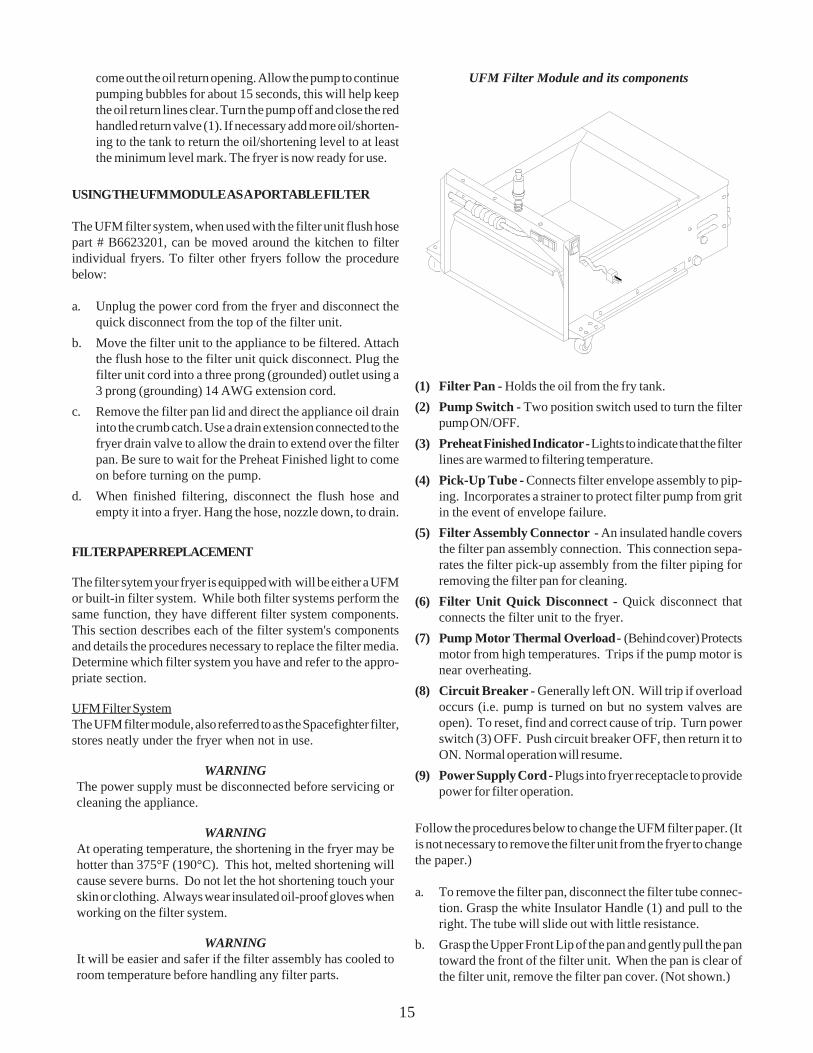
UFM Filter Module and its components
(1) Filter Pan - Holds the oil from the fry tank.(2) Pump Switch - Two position switch used to turn the filter
pump ON/OFF.(3) Preheat Finished Indicator - Lights to indicate that the filter
lines are warmed to filtering temperature.(4) Pick-Up Tube - Connects filter envelope assembly to pip-
ing. Incorporates a strainer to protect filter pump from gritin the event of envelope failure.
(5) Filter Assembly Connector - An insulated handle coversthe filter pan assembly connection. This connection sepa-rates the filter pick-up assembly from the filter piping forremoving the filter pan for cleaning.
(6) Filter Unit Quick Disconnect - Quick disconnect thatconnects the filter unit to the fryer.
(7) Pump Motor Thermal Overload - (Behind cover) Protectsmotor from high temperatures. Trips if the pump motor isnear overheating.
(8) Circuit Breaker - Generally left ON. Will trip if overloadoccurs (i.e. pump is turned on but no system valves areopen). To reset, find and correct cause of trip. Turn powerswitch (3) OFF. Push circuit breaker OFF, then return it toON. Normal operation will resume.
(9) Power Supply Cord - Plugs into fryer receptacle to providepower for filter operation.
Follow the procedures below to change the UFM filter paper. (Itis not necessary to remove the filter unit from the fryer to changethe paper.)
a. To remove the filter pan, disconnect the filter tube connec-tion. Grasp the white Insulator Handle (1) and pull to theright. The tube will slide out with little resistance.
b. Grasp the Upper Front Lip of the pan and gently pull the pantoward the front of the filter unit. When the pan is clear ofthe filter unit, remove the filter pan cover. (Not shown.)
16
c. Remove the crumb catch tray from the front of the filter pan.This is a “V” shaped screen that hangs on the Front UpperLip of the pan. Discard any debris that may be in the crumbcatch.
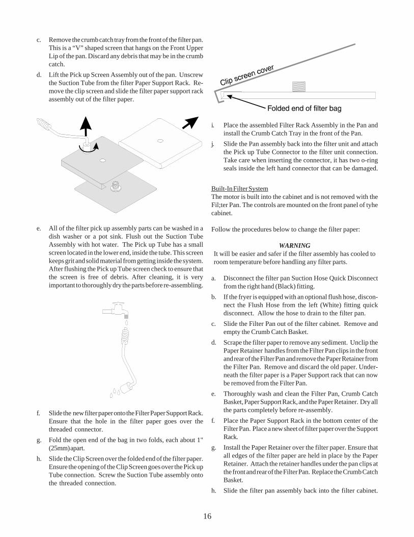
d. Lift the Pick up Screen Assembly out of the pan. Unscrewthe Suction Tube from the filter Paper Support Rack. Re-move the clip screen and slide the filter paper support rackassembly out of the filter paper.
e. All of the filter pick up assembly parts can be washed in adish washer or a pot sink. Flush out the Suction TubeAssembly with hot water. The Pick up Tube has a smallscreen located in the lower end, inside the tube. This screenkeeps grit and solid material from getting inside the system.After flushing the Pick up Tube screen check to ensure thatthe screen is free of debris. After cleaning, it is veryimportant to thoroughly dry the parts before re-assembling.
f. Slide the new filter paper onto the Filter Paper Support Rack.Ensure that the hole in the filter paper goes over thethreaded connector.
g. Fold the open end of the bag in two folds, each about 1"(25mm) apart.
h. Slide the Clip Screen over the folded end of the filter paper.Ensure the opening of the Clip Screen goes over the Pick upTube connection. Screw the Suction Tube assembly ontothe threaded connection.
i. Place the assembled Filter Rack Assembly in the Pan andinstall the Crumb Catch Tray in the front of the Pan.
j. Slide the Pan assembly back into the filter unit and attachthe Pick up Tube Connector to the filter unit connection.Take care when inserting the connector, it has two o-ringseals inside the left hand connector that can be damaged.
Built-In Filter SystemThe motor is built into the cabinet and is not removed with theFil;ter Pan. The controls are mounted on the front panel of tyhecabinet.
Follow the procedures below to change the filter paper:
WARNINGIt will be easier and safer if the filter assembly has cooled toroom temperature before handling any filter parts.
a. Disconnect the filter pan Suction Hose Quick Disconnectfrom the right hand (Black) fitting.
b. If the fryer is equipped with an optional flush hose, discon-nect the Flush Hose from the left (White) fitting quickdisconnect. Allow the hose to drain to the filter pan.
c. Slide the Filter Pan out of the filter cabinet. Remove andempty the Crumb Catch Basket.
d. Scrape the filter paper to remove any sediment. Unclip thePaper Retainer handles from the Filter Pan clips in the frontand rear of the Filter Pan and remove the Paper Retainer fromthe Filter Pan. Remove and discard the old paper. Under-neath the filter paper is a Paper Support rack that can nowbe removed from the Filter Pan.
e. Thoroughly wash and clean the Filter Pan, Crumb CatchBasket, Paper Support Rack, and the Paper Retainer. Dry allthe parts completely before re-assembly.
f. Place the Paper Support Rack in the bottom center of theFilter Pan. Place a new sheet of filter paper over the SupportRack.
g. Install the Paper Retainer over the filter paper. Ensure thatall edges of the filter paper are held in place by the PaperRetainer. Attach the retainer handles under the pan clips atthe front and rear of the Filter Pan. Replace the Crumb CatchBasket.
h. Slide the filter pan assembly back into the filter cabinet.
17
Connect the Filter Pan suction hose to the right (black) filterQuick Disconnect.
i. Slide the Crumb Catch Basket under the drain elbow. If theunit has the optional flush hose, connect the flush hose tothe left (white) fitting. Place the flush hose over the nozzlesupport rod on the Paper Retainer.
DAILY CLEANING
Your fryer should be cleaned every day to maintain peak perfor-mance and appearance. Perform the procedures below everyday.
a. Wipe up any oil/shortening that spills onto the exterior ofthe fryer. This should be done with a clean soft cloth whilethe oil is still warm.
b. Use warm water with a mild detergent to clean surfaces. Becareful not to get water in the oil/shortening and to removeany detergent from the fry tank.
c. Use a non-abrasive scouring powder or pad to clean stainsif necessary.
WEEKLY CLEANING
The fryer should be thoroughly cleaned once a week. Thiscleaning should include a complete draining of the fryer and aBoil Out as described in the Initial Cleaning section of thismanual.
FLUE INSPECTION
It is recommended that once every six monts, with the shut downand cooled down, you examine the flue area. Check for corrosionor blockage of the flue. Ensure that the fryer is shutdown anddo not turn it on during the examination. Examination of the fluearea during cooking may cause bodily injury.

18
Chapter 8 - Troubleshooting
Follow the procedures outlined in this section before calling for a service technician. This may say you time and money.
Fryer Problems (Standing Pilot):
PROBLEM POSSIBLE CAUSE SYMPTOM
Main burners come on as soon A. Loose fitting. A. Check and make sure all of theas the Gas Valve Knob is turned to tubing fittings at the Gas Valve andthe ON position. thermostat are tight.
Fryer consistently overheats A. Loose fittings. A. Check and make sure all of thetubing fittings at the Gas Valve andthermostat are tight.
Pilot will NOT light. A. Gas line NOT turned on or connected. A. Connect or turn ON and retry.
Pilot goes out when knob is released. A. Hi Limit tripped. A. Press Hi Limit button and retry.
Fryer will not maintain the A. Thermostat out of calibration A. Calibrate the thermostat astemperature set on the thermostat described in the INSTALLATIONknob. section of this manual.
Fryer Problems (Electronic Ignition):
Pilot Sparks but does NOT light A. Gas Valve Knob NOT turned ON. A. Check the position of the knob.

19

In the event of problems with or questions about your equipment,please contact your local ASAP (Authorized Service and Parts) rep-resentative. You can find their number by calling: (603)-225-6684
In the event of problems with or questions about your order,please contact the Pitco Frialator factory, from 8:00 a.m. - 5:00p.m., Eastern Standard Time, Monday through Friday, at:
(603)-225-6684.