Installation manual Central vacuum cleaning system Millennium ENG.pdf · Installation manual -...
24
m illennium Installation manual - millennium - 01/2010 - V1.0 Installation manual Central vacuum cleaning system 03/2010 - V 1.0 - ENG
Transcript of Installation manual Central vacuum cleaning system Millennium ENG.pdf · Installation manual -...

m i l lennium
Inst
alla
tion
man
ual
- m
illenn
ium
- 0
1/20
10 -
V1.
0
Installation manualCentral vacuum cleaning system
03/2010 - V 1.0 - ENG

2
Elek Trends Productions nvRue des Bengalis 4 | B - 7700 Moeskroen
Tel. +32 (0)56 48 15 90 | Fax +32 (0)56 48 15 91 | [email protected]
Inst
alla
tion
man
ual -
mille
nniu
m -
03/
2010
- V
1.0

INDEX
Inst
alla
tion
man
ual
- m
illenn
ium
- 0
1/20
10 -
V1.
0
1. Safety precautions, . . . . . . . . . . . . . . . . . . . . . . . . . . . . . . . . . . . . . . . . . . . . . . . . . . . . . . . . . . . .p52. Technical data sheet . . . . . . . . . . . . . . . . . . . . . . . . . . . . . . . . . . . . . . . . . . . . . . . . . . . . . . . . . .p63. Mounting, . . . . . . . . . . . . . . . . . . . . . . . . . . . . . . . . . . . . . . . . . . . . . . . . . . . . . . . . . . . . . . . . . . p7 Millennium, . . . . . . . . . . . . . . . . . . . . . . . . . . . . . . . . . . . . . . . . . . . . . . . . . . . . . . . . . .p74. Installation instructions, . . . . . . . . . . . . . . . . . . . . . . . . . . . . . . . . . . . . . . . . . . . . . . . . . . . . . . .p8 a. Position of the vacuum unit, . . . . . . . . . . . . . . . . . . . . . . . . . . . . . . . . . . . . . . . . . .p8 b. Position of the vacuum sockets, . . . . . . . . . . . . . . . . . . . . . . . . . . . . . . . . . . . . . . .p8 c. Planning the pipe system, . . . . . . . . . . . . . . . . . . . . . . . . . . . . . . . . . . . . . . . . . . . . .p8 d. Example showing where to fi t vacuum sockets, . . . . . . . . . . . . . . . . . . . . . . . . .p11 e. Understanding, . . . . . . . . . . . . . . . . . . . . . . . . . . . . . . . . . . . . . . . . . . . . . . . . . . . .p12 f. The principles, . . . . . . . . . . . . . . . . . . . . . . . . . . . . . . . . . . . . . . . . . . . . . . . . . . . . .p12 g. The pipework, . . . . . . . . . . . . . . . . . . . . . . . . . . . . . . . . . . . . . . . . . . . . . . . . . . . . .p12 h. The pipe fi ttings, . . . . . . . . . . . . . . . . . . . . . . . . . . . . . . . . . . . . . . . . . . . . . . . . . . .p12 i. The pipe work, . . . . . . . . . . . . . . . . . . . . . . . . . . . . . . . . . . . . . . . . . . . . . . . . . . . .p13 j. The electrical supply (12V), . . . . . . . . . . . . . . . . . . . . . . . . . . . . . . . . . . . . . . . . . . .p13 k. Milllennium range of PVC vacuum sockets . . . . . . . . . . . . . . . . . . . . . . . . . . . . .p16 l. Range of Stainless steel vacuum sockets . . . . . . . . . . . . . . . . . . . . . . . . . . . . . . .p16 m. Installation materials, . . . . . . . . . . . . . . . . . . . . . . . . . . . . . . . . . . . . . . . . . . . . . . .p175. General notes, . . . . . . . . . . . . . . . . . . . . . . . . . . . . . . . . . . . . . . . . . . . . . . . . . . . . . . . . . . . . . .p18 Vacuum sockets, . . . . . . . . . . . . . . . . . . . . . . . . . . . . . . . . . . . . . . . . . . . . . . . . . . . . .p18 Internal pipe work, . . . . . . . . . . . . . . . . . . . . . . . . . . . . . . . . . . . . . . . . . . . . . . . . . . .p18 External pipe work, . . . . . . . . . . . . . . . . . . . . . . . . . . . . . . . . . . . . . . . . . . . . . . . . . .p18 Conclusion . . . . . . . . . . . . . . . . . . . . . . . . . . . . . . . . . . . . . . . . . . . . . . . . . . . . . . . . .p186. Use and maintenance . . . . . . . . . . . . . . . . . . . . . . . . . . . . . . . . . . . . . . . . . . . . . . . . . . . . . . .p207. Important safety instructions, . . . . . . . . . . . . . . . . . . . . . . . . . . . . . . . . . . . . . . . . . . . . . . . . .p21

4
Inst
alla
tion
man
ual -
mille
nniu
m -
03/
2010
- V
1.0

5
Inst
alla
tion
man
ual
- m
illenn
ium
- 0
1/20
10 -
V1.
0
1. SAFETY PRECAUTIONS
For the correct and safe installation of the central vacuum cleaner, the following is important:
- Carefully read the complete manual before starting assembly!- Observe the applicable safety instructions regarding fi re, working on electricity and buildings!- Always use the correct tools!- Replace defective parts only with original spares. If you do not do this, the safe and proper operation of the door can not be guaranteed! In such a case the guarantee becomes void!- The components that are used are made of high quality, durable and solid materials. However, these components must be mounted with great care to avoid them from damaging.- Failure to follow these instructions can result in serious injury or material damage.- When having fi nished the installation, make sure that this instruction and assembly manual is given to the end-user.- This machine is not meant to be used by children nor by people with a mental illness, unless they have been informed about the use and the dangers.

6
millennium
Inst
alla
tion
man
ual -
mille
nniu
m -
03/
2010
- V
1.0
millennium
2. TECHNICAL DATA SHEET
general data• Remote control 12V-DC with safety transfo acc.: VDEO551• EMF-Printed circuit (compulsory since 1/1/1996• Motors 220-250V, 50Hz, insulation class E (acc. IEC publication ‘85)• To install, only in dry rooms• Finishing : Millennium : in PC/ABS
WHEN STIPULATING ENGINE TYPE TAKE INTO ACCOUNT ALTITUDE ABOVE SEA LEVEL
TYPE MI 1251 MI 1411 MI 1451 MI 1511 MI 2411 MI 2001
Motor 230V Through Flow By-Pass By-Pass By-Pass By-Pass By-Pass
Primary fi lter Paper fi lter Brano Cyclonic Cyclonic Cyclonic Cyclonic Cyclonic
Secondary fi lter Foam fi lter Textil fi lter Textil fi lter Textil fi lter Textil fi lter Textil fi lter
Nom. power 1400 W 1200 W 1200 W 1200 W 1750 W 1200 W
Max. Power 1610 W 1560 W 1355 W 1536 W 1850 W 1450 W
Max. durrent 6.5 A 6.0 A 5.4 A 7.0 A 8.5 A 5.5 A
Base motor 139 mm 145 mm 145 mm 145 mm 145 mm 183 mm
Turbine 1stage 3 stages 3 stages 3 stages 3 stages 3 stages
Neg. pressure 3020 mmH2O 2733 mmH2O 2964 mmH2O 3482 mmH2O 3651 mmH2O 3289 mmH2O
Max. Air fl ow 51,6 l/sec 48,1 l/sec 44,2 l/sec 44,7 l/sec 52,7 l/sec 41,9 l/sec
Max. Airwatts 587 380 348 448 627 372
Dia. air outlet Intern 50 mm 50 mm 50 mm 50 mm 50 mm
Cap. dust container 18 l 18 l 18 l 18 l 18 l 18 l
Number of sockets : 5 7 8 10 15 12
(indicatives values)
Max. distance 20 m 20 m 25 m 35 m 50 m 35 m
Dimensions (m) 0,38 x 1,00 x 0,40 0,38 x 1,00 x 0,40 0,38 x 1,00 x 0,40 0,38 x 1,00 x 0,40 0,38 x 1,00 x 0,40 0,38 x 1,00 x 0,40
Installed dimensions (m) 0,75 x 1,40 x 0,75 0,75 x 1,40 x 0,75 0,75 x 1,40 x 0,75 0,75 x 1,40 x 0,75 0,75 x 1,40 x 0,75 0,75 x 1,40 x 0,75

7
1 1
2 2
3 3
4 4
5 5
6
millennium
MI 1251 MI 1411 / MI 1451 / MI 1511 / MI 2411 / MI 2001
MI 2411m i l lennium
FULL
MI 2411m i l lennium
FULL
a
b
c
d
e
h
g
f
Inst
alla
tion
man
ual
- m
illenn
ium
- 0
1/20
10 -
V1.
0
1. Suction conduit pipes for basement & ground fl oor2. Suction conduit pipes for fl oors3. Min. distance of 30cm to the ceiling4. 12V wire connection unit5. Power cord connection unit6. Silencer
a. Motor coverb. Motorc. Filter housingd. Textile fi ltere. Dust containerf. Exhaust air outletg. Air inlet: PVC-tube 50mm or 2”h. Bayonet fi xing for bin
3. MOUNTING

8
Inst
alla
tion
man
ual -
mille
nniu
m -
03/
2010
- V
1.0
A. Position of Vacuum unit
This should be sited away from the living areas but remain accessible. Garages and basements are ideal. It needs to be mounted on a wall at a height which allows the dust container to be removed easily. For preference, the vacuum unit should be fi tted at the lowest convenient point. Ideally, it should be installed so that the vacuum unit is less than 3m above the lowest point in the system. It should not be installed where it is damp or where it can get wet. The ambient temperature should be preferably not exceed 30°C and the area where the unit is sited should be ventilated. Some of the smaller models MI1251/Premium—have through fl ow motors, which means that the air sucked in by the vacuum fan is exhausted to atmosphere through the motor in order to cool it. All the other models have by-pass motors, meaning that there is a separate cooling fan on the motor and that the air from the vacuum fan is vented to atmosphere through an exhaust pipe. Apart from the smaller models, all units need to be vented outside the building. Allow enough space for a silencer if required—a silencer is approximately 30cm long. When stipulating engine type take into account altitude above sea level. The technical data in the table have been based on 10m above the sea level. By 100 meters above this altitude 10mBar uplift must be added (1000 mm/Ws correspond to 100mbar suction power)
B. Position of vacuum sockets The general rule is to site these centrally within a building in order that as much fl oor area can be covered with the minimum
number of sockets. It is not necessary to install a socket in each room—position the sockets so as to cover as large an area as
possible. If using a 7.5m hose, each socket can provide approximately 50 to 60m2 cover, while a 10m hose will cover 70 to 80m2.
In an existing building, real distances can be measured, but if planning a new installation from drawings, it will be necessary to
use a scale rule to determine where to site the sockets. When planning from drawings, keep in mind that a hose will have to go
around furniture and other obstructions which do not yet exist. It may not be so easy to put them in the ideal position. As they are
inexpensive and easy to install, its is better to put in two sockets in less than ideal positions rather than struggle to install one socket
in the perfect position. The sockets can be installed either in the walls or the fl oor.
C. Planning the pipe system
Ideally this should be as short as possible. The position of the sockets will probably be determined by how easy it is to get the
pipework to the position selected for the sockets. The choice will probably depend on the construction of the building. The pipe
work connecting sockets to vacuum sockets is best run through the building’s natural voids: for example, under the fl oor, inside stud
walls and in the space between ground fl oor ceiling and the fi rst fl oor.
If it is diffi cult to design a network of piping which allows the sockets to be put in the optimum position by using the fl oor voids,
then the solution may be to take the main run of pipe directly into the roof space and run the pipes down to individual sockets
from there. The following page illustrates some of the possible arrangements for installing vacuum sockets in walls. The same
principles apply when installing vacuum sockets in the fl oor. Both PVC “Millennium”or a stainless steel “Design” socket can be used
for wall installation. However for fl oor installation, only the “Design” range is recommended.
4. PLANNING A CENTRAL VACUUM SYSTEM

9
1
1
3
4
2
5
2
3
4 5
6
Inst
alla
tion
man
ual
- m
illenn
ium
- 0
1/20
10 -
V1.
0
1. Stud wall2. Vacuum socket3. Floor4. 50mm pipe inside stud wall5. Low voltage cable attached to pipe6. Millennium extension piece
1. Solid wall2. Vacuum socket3. 50mm pipe inside wall4. low voltage cable attached to pipe5. Floor
Ideally vacuum sockets are installed in stud walls, so that the pipe connected to the socket runs within the wall. See diagram on left. These fi ttings have a fi tted depth of between 75 & 90mm. If the fi tting is deeper in the wall, an extension piece can be used between the socket & any Millennium fi tting if the fi tting is set too far back into the wall. It extends the spigot to an extra 25mm.
Millennium 90° elbow fi tting (sharp bed) with plasterguard fi tted.
If the wall is solid, leave (or make) a channel in the brickwork in order to accomodate this arrangement-see diagram on right.

10
Inst
alla
tion
man
ual -
mille
nniu
m -
03/
2010
- V
1.0
Sometimes, it is not possible to run the pipe within the wall as shown in the above diagrams. In this instance, use a Millennium straight fi tting connected to a straight piece of pipe running through to the back of the wall. Two other arrangements are shown below using a separate sharp 90° knuckle bend, which should be fi tted as close to the vacuum socket as possible.) This is important as it is this bend which will prevent long thin objects from entering the system and possibly causing a blockage. If an object does get stuck in this bend, one must be able to retrieve it from the vacuum socket.
Pipe chased into rear of wall with separate 90° bend
Millennium straight fi tting with plasterguard fi tted

11
Inst
alla
tion
man
ual
- m
illenn
ium
- 0
1/20
10 -
V1.
0
D. Example diagram showing where to fi t vacuum sockets
This represents a house with a total fl oor area of approximately 400m2. It is a 6 bedroom house with generously proportioned rooms. The ground fl oor covers approximately 150m2 plus a garage of 45m2 making a total of about 200m2. There is the same fl oor area upstairs.
By placing the inlet sockets strategically, 2 sockets can provide cover for the ground fl oor of the house using a 10m fl exible hose. This is shown by the lines with arrowheads on the drawing. A utility socket can be fi tted near to the garage entrance so that the vacuum hose can be used to clean cars inside and outside the garage.
The fi rst fl oor can be served by 2 sockets on the landing directly above the 2 sockets in the hall. The room over the garage would be covered by a socket on the fi rst fl oor directly above the vacuum unit.
This house would need a total 6 vacuum sockets—5 built-in sockets & one utility socket.If a shorter (7,5m) fl exible hose were to be used, then an extra socket would be required on each fl oor and the vacuum sockets would need to be re-sited.
Garage
Vacuum unit
Utility vacuum socket
Store
Pantry
Kitchen
Dining room
Hall
Sitting room
TV room/Study
12
Inst
alla
tion
man
ual -
mille
nniu
m -
03/
2010
- V
1.0
E. Understanding
The principle of a central vacuum system is as important as understanding the mechanics of the installation.Following these guidelines should ensure that the installation is easily accomplished and that the pipework will not become blocked in use.
F. The principles
The system is designed so that it will not become blocked in normal domestic use. The narrowest part is the point at which items are sucked into the system, this being the brush or tool on the end of the hand-held wand. The diameter of the tubing gets progressively larger so that if an item can pass through the suction tool, then it will pass through the rest of the system. The internal pipe diameter of a suction hose is 32mm, it increases to 43mm at the 90° elbow and again to an I.D. of 46mm for the main run of pipe. If an item is small enough to pass through the 32mm pipe, then it will pass through the 43mm bend and the 50mm pipe easily.
It is possible to suck a long thin item, such as a pencil, into the vacuum system. This could pass through all the pipework until it reached a bend where it could become stuck and cause a blockage. However this is prevented by the use of a sharp right-angle bend behind the vacuum socket. As the pipe immediately after the bend is larger than the socket’s internal diameter and all subsequent bends are 45° bends or swept 90° bends, then anything that can pass through this sharp 90° bend will pass unhindered through the rest of the system. If a pencil is sucked into the system, it will become lodged in the sharp 90° bend (elbow fi tting) behind each socket and can be removed through the vacuum socket.
G. The pipework
Imagine the pipework as a simple tree with the longest run of pipework as the trunk, the shorter runs as branches and the vacuum unit as the root. The trunk & branches may need to have a few bends in them in order to fi t the building and, as with most trees, the branches join the trunk at an angle pointing in the direction of the roots. In a central vacuum system, the branches of the pipework must join the main run at an angle using a swept 90° tee or 45° tee (see diagrams)
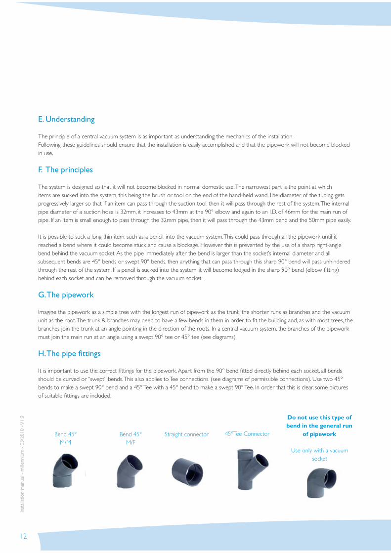
H. The pipe fi ttings
It is important to use the correct fi ttings for the pipework. Apart from the 90° bend fi tted directly behind each socket, all bends should be curved or “swept” bends. This also applies to Tee connections. (see diagrams of permissible connections). Use two 45° bends to make a swept 90° bend and a 45° Tee with a 45° bend to make a swept 90° Tee. In order that this is clear, some pictures of suitable fi ttings are included.
Bend 45°M/M
Bend 45°M/F
Straight connector 45°Tee Connector
Use only with a vacuum socket
Do not use this type of bend in the general run
of pipework

13
Inst
alla
tion
man
ual
- m
illenn
ium
- 0
1/20
10 -
V1.
0
I . The pipework
This is 50mm (outside) diameter and is normally supplied with the vacuum unit. When installing pipework, start at the vacuum socket and work back to the vacuum unit. Initially fi t the components together without glue to make sure all the parts fi t properly as the solvent glue dries very quickly, and once set, the components will not come apart. It will aid the effi ciency of the system if the inside of the pipe is as smooth as possible. This can be achieved by making sure that all cuts to the pipe are square and rough edges removed with a fi ne fi le or sand paper. The pipes should be pushed fi rmly into any connector so that the end of the pipe butts up against the lip inside the connector.
It is most important : that the solvent glue is applied to the outside of the pipe (or the male part of any fi tting) when making a connection. This is so that any excess glue is sqeeuzed out of the joint to the outside of the pipe where it is harmless. Avoid excess glue on the inside of the pipe. Before applying glue to a joint, make sure that both surfaces are clean and free from grease. If necessary wipe both surfaces with a clean cloth and solvent such as acetone (nail varnish remover). Apply adequate glue to male side of the joint and insert into female side, twisting the 2 parts as you do so in order ensure that the glue is evenly spread and a sound joint is formed. Where this is diffi cult to achieve due to restricted access, fi t the items without glue, make a mark across the joint(s), remove items and glue together with the marks aligned. Components can then be fi tted as an assembly. For maximum effi ciency, it is important that there are no leaks in the system.
J. The electrical supply
The vacuum unit is permanently connected to the mains electricity. All domestic models can be run from a normal electrical socket. Each vacuum unit has an internal transformer which provides 12V to a pair of terminals at the rear of the vacuum unit. These are connected to a pair of contacts on the back of each vacuum socket using bell wire or speaker cable (2 x 0,75mm2 side by side). The 12V connections to the sockets should be in parallel. It is not necessary to run a cable from each socket back to the vacuum unit or from one socket to the next. The cable from each socket can follow the pipe and two cables can be joined with a connector wherever a run of pipe joins another, so that there is only one pair of wires going back to the vacuum socket.
Important—Commissioning When the pipework and wire have been installed, check the continuity of the wiring. At each socket, make sure that the 2 ends of the wire are not touching & check the circuit by putting an ohmmeter across the 2 ends of the cable at the vacuum unit end. It should be an open circuit. Now test the wiring to each socket in turn by twisting the 2 ends of the wire together at the socket end.

14
Inst
alla
tion
man
ual -
mille
nniu
m -
03/
2010
- V
1.0
Only test one socket at time Check the circuit again at the vacuum unit end-it should be a closed circuit. Separate the 2 ends of the wire at the fi rst socket before testing the second. Repeat for each socket. When the end of the fl exible suction hose is inserted into the vacuum socket, the circuit is completed and a 12 volt signal is sent to the vacuum unit. The vacuum unit starts and will run until the fl exible hose is removed from the socket. (There is an option to have a switch in the handle of the fl exible hose which allows the vacuum unit to be switched on and off without removing the hose from the socket.) The cable from the 12 Volt terminals connect to each of the sockets in parallel. It can be attached to the pipework using cable ties or tape. If buried in the wall or fl oor, it should be protected by conduit .
A 90° socket fi tting with signal cable fi tted. Pass cable through a hole drilled in the rear of 90° socket fi tting. Tie a knot in the cable to stop it falling back and feed the excess wire back down the pipe ready for connection to terminals on rear of socket after walls have been plastered / plaster boarded. Re-fi t plasterguard if necessary. The front face of the box should be fi tted to the front face of the studwork—the level with the rear of the plasterguard. The level with the rear of the plasterguard. The spigot on the rear of the socket has maximum 20mm reach so can be fi tted through 12.5mm plasterboard into the hole in the socket fi tting.
Rear of a socket showing12V parallel connections
Note:If the O’ring on the back of the vacuum socket made wet, it ismuch easier to fi t (or remove if necessary)
Drill out of the holes on the back off the box of the socket fi tting & put low
voltage cable through for connection to terminals on back of socket
NBSecure box to studwork with 2 screws though the side of the box.
15
Inst
alla
tion
man
ual
- m
illenn
ium
- 0
1/20
10 -
V1.
0
Vertical pipe
The same principle applies to fi tting a socket box in a solid wall. The front face of the box can be anywhere from being fl ush with the fi nished surface (usually plaster) to 20mm behind the fi nished surface, although fi tting sockets is easier if the box is somewhere between 5 & 15mm beneath the fi nished surface. Secure box to wall. A screw through the back of the box will do as well as a generous squirt of Gripfi ll or similar fi xative. Dont screw the screws of the vacuum sockets to deep.
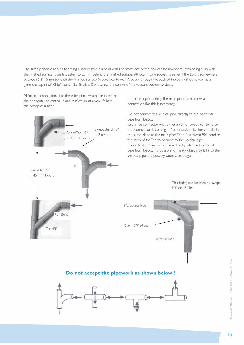
This fi tting can be either a swept 90° or 45° Tee
Make pipe connections like these for pipes which join in either the horizontal or vertical plane. Airfl ow must always follow the sweep of a bend.
If there is a pipe joining the main pipe from below, a connection like this is necessary..
Do not connect the vertical pipe directly to the horizontal pipe from below.Use a Tee connector with either a 45° or swept 90° bend so that connection is coming in from the side –i.e. horizontally in the same plane as the main pipe. Then fi t a swept 90° bend to the stem of the Tee to connect to the vertical pipe. If a vertical connection is made directly into the horizontal pipe from below, it is possible for heavy objects to fall into the vertical pipe and possibly cause a blockage.
Do not accept the pipework as shown below !
Swept Tee 45°+ 45° MF bocht
Swept Tee 45°+ 45° MF bocht
Swept Bend 90°= 2 x 45°
Horizontal pipe
Swept 90° elbow
45° Bend
Tee 45°

16
Inst
alla
tion
man
ual -
mille
nniu
m -
03/
2010
- V
1.0
K. Millennium range of PVC vacuum sockets
Profi le of PVC Vacuum socket
Section through 90° socket fi tting for PVC vacuum socket
Face plate of PVC vacuum socket is 80mm x 80mm
Face plate can be installed upside down so that lid hinged at bottom
Minimum installed depth 72mmMax.imum installed depth 90mm
Max. distance between rear of socket face plate and front of socket fi tting =20mm.
L. Designer range of stainless steel vacuum sockets
Profi le of stainless steel vacuum socket - Designer range
Face plate of Designer range stainless steel vacuum socket is 95 x 80mm
Section through 90° Designer socket fi tting
Max. distance between rear of socket face plate and front of socket fi tting = 20mm
Minimum installed depth 80mmMaximum installed depth 100mm
The Designer range of vacuum sockets can be fi tted in either wall or fl oors

17
Inst
alla
tion
man
ual
- m
illenn
ium
- 0
1/20
10 -
V1.
0
M. Installation materials
45° F/Felbow
45° F/Felbow
45° Tee 50mm Straight connector
PVC-pipe 50 x 1,8mm
50 mm pipe clip Exhaust grid Elbow fi tting 90° Straight fi tting 90°M/F elbow for use straight fi tting only
Tee fi tting Utility elbow socket Utility tee socket Silencer Heavy duty fl exible hose for use underground

18
Inst
alla
tion
man
ual -
mille
nniu
m -
03/
2010
- V
1.0
Vacuum sockets
It is conventional for vacuum sockets to be fi tted so that the cover opens upwards—i.e. it is hinged at the top of the socket. For this reason the socket fi ttings (boxes) are marked with an arrow and ‘UP’ to show the correct way to fi t them. However, it is easier to insert the end of the hose into a vacuum socket if it opens downwards (picture above) so that the hole in the socket is exposed as the fl ap starts to open. If this arrangement is required, then the fi ttings must be installed with the arrow and ‘UP’ at the bottom, not the top, of the fi tting. When using the 90° elbow fi tting, rotate the box on the end of the tube, if necessary (picture above right).
Internal pipe work It is important to note (and preferably mark) the route of the pipe through the building when it is not obvious that there is a pipe under the fl oor or in a wall. This is especially important during construction as not all artisans will be familiar with a central vacuum system and may inadvertently damage the pipework. A nail through the pipe will soon cause a blockage and fractured pipe will lead to a loss of suction.
External pipe work It is assumed that the pipework will be run within a building, but sometimes it is necessary to run a pipe outside—to a detached garage, for example. In this case, it is important that the pipe be insulated from extreme cold in order to prevent condensation in the pipe, although short runs of unprotected pipe should not be a problem. If it is necessary to run a pipe to another building, the rigid PVC should be buried at least 50cm deep and protected, preferably by putting it inside a larger diameter pipe. This not only gives a degree of insulation, but also provides some protection against ground movement. Alternatively, a reinforced heavy duty fl exible hose can be used underground. Whilst this hose is more costly, it is a lot easier & quicker to lay. Ensure all joints are glued well and that there is no opportunity for ingress of water to the system. If a pipe runs outside a building in a position where it can get very cold, it should be lagged and boxed (or run inside a larger pipe).
And FinallyHaving installed a vacuum system in a new house, many people are tempted to take advantage of its impressive performance to clean up the site. Please be aware that cement and plaster dust will stick to the heavy duty textile fi lter inside the vacuum unit and cause a loss of performance. This can be overcome by removing the dust bin from the unit and shaking the fi lter vigorously (see directions for use in the unit), and if necessary, removing the fi lter from the canister. Alternatively, do not use the Central Vacuum Cleaner for cleaning a building site!
5. GENERAL NOTES

19
Inst
alla
tion
man
ual
- m
illenn
ium
- 0
1/20
10 -
V1.
0
Place the hose and tool rack on the wall at eye level.
Place the hose in a few big circles round the hose and tool rack; there is also place for the suction mouths.
Choose the right suction mouth for every work.
• For smooth fl oors and parquet : the long brush with hairs (1.0300.1001)• For carpet : the adjustable carpet tool with hairs drawn in so the metal level pushes against the carpet. (1.0300.1000)• For furniture and rough levels : the circular dusting brush (1.0300.1005)• For seats and the car : the upholstery tool (1.0300.1003)• For corners and crevices : the crevice tool, which increases the suction power due to it’s little opening. (1.0300.1004)• Link up the two chromed extension tubes (1.0310.1000) with the grip (1.0210.1001) to clean the soil.• Lay the hose always open before getting started, short bends obstacle the air speed and the suction capacity.• Empty the dustbin of the central vacuum cleaner regularly. Look the fi rst time after about 1 month, in this way you’ll know in the future how many times you have to empty it in one year.• When the suction power decreases, empty the dustbin and clean the fi lter according to the type of unit (see directions for use on the unit) - With some of the units the foam fi lter is pulled around a carton fi lter system. The carton fi lter has to be, before mounting the foam fi lter, beaten outside very well to clear. - With the fi ltersystem with paper bag is also a foam foreseen. There is no spare one, because it normally doesn’t get dirty. Only when the paper bag thorns up; the protection fi lter must be washed and put back. - For the units with a textile fi lter, one can beat the textile fi lter to remove the fi ne dust parts after emptying the dustbin.• When the automatic fuse switches of regularly , notify the installer
6. USE AND MAINTENANCE

20
Inst
alla
tion
man
ual -
mille
nniu
m -
03/
2010
- V
1.0
NOTE! To reduce the risk of fi re, electric shock or injury, read all safety precautions and warning text carefully before using the machine.
• These central vacuum cleaners are solely intended for dry vacuuming indoors.
• Do not vacuum up liquids unless a special wet pick-up separator unit is used.
• Do not vacuum near smoke, naked fl ames or fi re, e.g. cigarettes, matches, hot ash or fl ammable liquid or gas.
• Do not vacuum in areas where fl ammable liquids or gases may be present.
• In case of a blockage, the motor should be stopped to avoid overheat.
• Unplug the machine before changing the fi lter or bag before doing any maintenance work.
• Always unplug the machine by pulling on the plug, not the power cord.
• The wall socket and plug must be positioned so that they are clearly visible.
• Do not vacuum up sharp objects such as broken glass that could puncture the dust bag unless an interceptor kit is used.
• Do not cover the central unit or restrict its intake port.
• Follow the operating instructions carefully. Servicing and repairs should only be carried out by an authorised workshop. Use only parts and accessories recommended by the manufacturer. Never attempt to modify the central vacuum cleaner in any way.
• Do not use the central vacuum unit if the power cord is damaged. The central vacuum cleaner is fi tted with a special type of power cord that must be replaced with a cord of the same type if it is damaged. This can be obtained from an authorised service workshop. To avoid danger the power cord should be replaced by an approved Elek Trends engineer.
• The central vacuum cleaner is very powerful and should never be used as a toy by children.
• Never vacuum without a fi lter dust bag fi tted to the machine.
• Warning! The central vacuum cleaner must not be used to clean up hazardous waste.
7. IMPORTANT SAFETYPRECAUTIONS

21
NOTES
Inst
alla
tion
man
ual
- m
illenn
ium
- 0
1/20
10 -
V1.
0

22
NOTES
Inst
alla
tion
man
ual -
mille
nniu
m -
03/
2010
- V
1.0

23
Inst
alla
tion
man
ual
- m
illenn
ium
- 0
1/20
10 -
V1.
0

Elek Trends Productions nvRue des Bengalis 4 | B - 7700 Moeskroen
Tel. +32 (0)56 48 15 90 | Fax +32 (0)56 48 15 91 | [email protected]
Inst
alla
tion
man
ual -
mille
nniu
m -
03/
2010
- V
1.0