INSTALLATION MANUAL AND OPERATING … · 2014-04-09 · installation manual and operating...
24
INSTALLATION MANUAL AND OPERATING INSTRUCTIONS ARGO ARM SERIES SwITChING RELAyS wITh PRIORITy ARm-2P, ARm-3P, ARm-4P, ARm-6P, AD-1, AD-4 P/N 240005129, Rev. A [06/08] An ISO 9001-2000 Certified Company AD-1 AD-4 ARM-2P ARM-3P ARM-4P ARM-6P ARGO (Technical Support) 2201 Dwyer Avenue Utica, NY 13501 (Corporate Sales) 85 Middle Road Dunkirk, NY 14048 www.argocontrols.com
Transcript of INSTALLATION MANUAL AND OPERATING … · 2014-04-09 · installation manual and operating...

INST
ALLA
TIO
N M
ANUA
L AN
D O
PERA
TIN
G IN
STRU
CTIO
NS
ARGO ARM SERIES SwITChING RELAySwITh PRIORITy
ARm-2P, ARm-3P, ARm-4P, ARm-6P, AD-1, AD-4
P/N 240005129, Rev. A [06/08]
An ISO 9001-2000 Certified Company
AD-1
AD-4
ARM-2P
ARM-3P
ARM-4P
ARM-6P
ARGO (Technical Support)2201 Dwyer AvenueUtica, NY 13501
(Corporate Sales)85 Middle RoadDunkirk, NY 14048www.argocontrols.com

3
instAllAtiOn mAnuAlAnd OpeRAtinG instRuctiOns
tABle OF cOntents
Safety Symbols and Warnings .......................................................4Introduction .....................................................................................5Product Features ............................................................................5Mounting Instructions .....................................................................7Electrical Specifications & Wiring ...................................................8Sequence of Operation...................................................................9ARM-4P Wiring Schematic ...........................................................10ARM “Cold Start” Applications ......................................................11ARM “Tankless Coil” Applications .................................................15ARM With AD Expansion Modules ...............................................18ARM To Field Replacement Transformer .....................................18ARM With DPM-2 Outdoor Reset Control ...................................21ARM With Power Robbing Thermostat .........................................22Replacement Parts .......................................................................23Technical Support .........................................................................23
160627
4
! !
! !
! !
! !
RetAin tHis mAnuAl FOR FutuRe ReFeRence
sAFetY sYmBOls And wARninGs
The following defined symbols are used throughout this manual to notify the reader of potential hazards of varying risk levels.
dAnGeR
indicates an imminently hazardous situation which, if not avoided, will result in death or serious injury.
wARninG
indicates a potentially hazardous situation which, if not avoided, cOuld result in death or serious injury.
cAutiOn
Indicates a potential hazardous situation which, if not avoid-ed, MAY result in minor or moderate injury. It may also be used to alert against unsafe practices.
impORtAnt: Read the following instructions COMPLETELY before installing!!
wARninG
All installations should be done only by a qualified expert and in accordance with the appropriate Argo manual. in-stalling an electric appliance with improper methods or materials may result in serious injury or death due to fire.
5
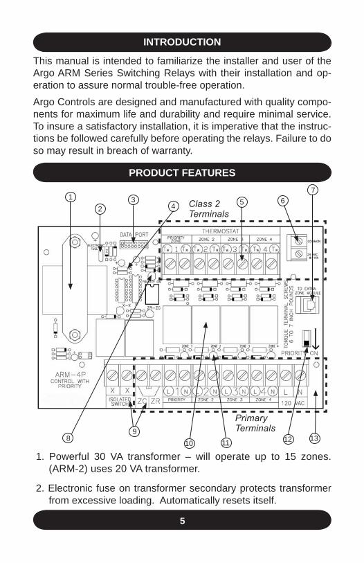
intROductiOn
This manual is intended to familiarize the installer and user of the Argo ARM Series Switching Relays with their installation and op-eration to assure normal trouble-free operation.Argo Controls are designed and manufactured with quality compo-nents for maximum life and durability and require minimal service. To insure a satisfactory installation, it is imperative that the instruc-tions be followed carefully before operating the relays. Failure to do so may result in breach of warranty.
1. Powerful 30 VA transformer – will operate up to 15 zones. (ARM-2) uses 20 VA transformer.
2. Electronic fuse on transformer secondary protects transformer from excessive loading. Automatically resets itself.
pROduct FeAtuRes
12
34 5 6
7
98
10131211
Class 2Terminals
PrimaryTerminals
6
3. Data Port terminal allows for an easy connection of the DPM-2 outdoor reset control.
4. Three second time delay for boiler shutoff.
5. 24 VAC transformer terminals – for easy connection of 3-wire thermostats and field replacement of transformer.
6. Clearly marked terminals with clamping plates and plenty of room for wiring.
7. Expansion module plug-in – makes adding zone(s) easy and economical through the use of the Argo AD-1 & AD-4 expansion modules.
8. Priority zone safety timer – Priority feature will turn off (light off) temporarily if priority zone calls for heat longer than 30 minutes, allowing all zones to operate independently of each other. Re-peats every 30 minutes.
9. Separate X-X (isolated switch) and ZC-ZR relays protect boiler aquastat – can be used with either “cold start” or “tankless coil” boiler application. ARM-2 controls do not have ZC-ZR terminals.
nOte: that terminals ZC-ZR are 120VAC Connections.
10. Plug-in replaceable relays for long life. High relay load rating – 1/3 HP. U.L./CSA listed.
11. LED lights turn on when relay contacts are closed. Makes for easy troubleshooting by indicting relay operating status.
12. Switchable priority improves versatility.
13. Double sided printed circuit board construction 100% factory tested. Advanced printed circuitry compatible with most pro-grammable thermostats.
nOte: The 4-zone ARM-4P is featured in this manual. The ARM2-P, ARM-3P, and ARM-6P circulator relays have identical electrical specifications. Differences in operating features are noted in this manual.
14. The ARM Series Switching Relays have a 5-year warranty, while AD Expansion Modules have an 18-month warranty.
pROduct FeAtuRes continued
7
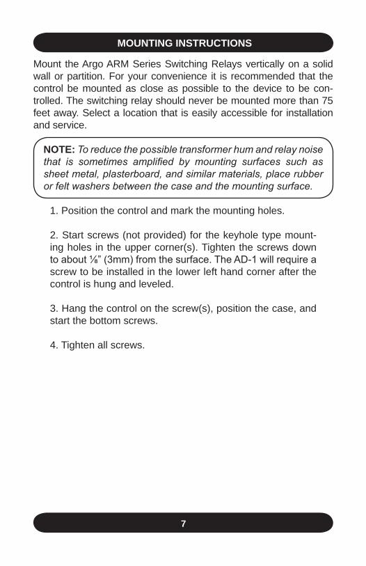
mOuntinG instRuctiOns
Mount the Argo ARM Series Switching Relays vertically on a solid wall or partition. For your convenience it is recommended that the control be mounted as close as possible to the device to be con-trolled. The switching relay should never be mounted more than 75 feet away. Select a location that is easily accessible for installation and service.
nOte: To reduce the possible transformer hum and relay noise that is sometimes amplified by mounting surfaces such as sheet metal, plasterboard, and similar materials, place rubber or felt washers between the case and the mounting surface.
1. Position the control and mark the mounting holes.
2. Start screws (not provided) for the keyhole type mount-ing holes in the upper corner(s). Tighten the screws down to about ⅛” (3mm) from the surface. The AD-1 will require a screw to be installed in the lower left hand corner after the control is hung and leveled.
3. Hang the control on the screw(s), position the case, and start the bottom screws.
4. Tighten all screws.
8
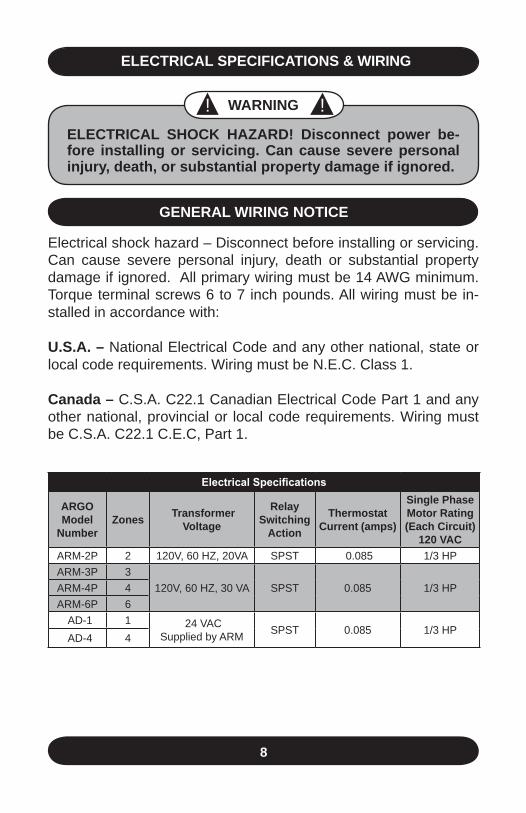
electRicAl speciFicAtiOns & wiRinG
Electrical Specifications
ARGOmodel
number Zones transformer
voltage
Relayswitching
Action
thermostat current (amps)
single phasemotor Rating(each circuit)
120 vAcARM-2P 2 120V, 60 HZ, 20VA SPST 0.085 1/3 HPARM-3P 3
120V, 60 HZ, 30 VA SPST 0.085 1/3 HPARM-4P 4 ARM-6P 6 AD-1 1 24 VAC
Supplied by ARM SPST 0.085 1/3 HP AD-4 4
! ! wARninG
electRicAl sHOck HAZARd! disconnect power be-fore installing or servicing. can cause severe personal injury, death, or substantial property damage if ignored.
GeneRAl wiRinG nOtice
Electrical shock hazard – Disconnect before installing or servicing. Can cause severe personal injury, death or substantial property damage if ignored. All primary wiring must be 14 AWG minimum. Torque terminal screws 6 to 7 inch pounds. All wiring must be in-stalled in accordance with:
u.s.A. – National Electrical Code and any other national, state or local code requirements. Wiring must be N.E.C. Class 1.
canada – C.S.A. C22.1 Canadian Electrical Code Part 1 and any other national, provincial or local code requirements. Wiring must be C.S.A. C22.1 C.E.C, Part 1.
9
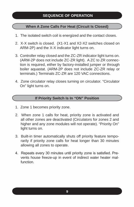
sequence OF OpeRAtiOn
when A Zone calls For Heat (circuit is closed)
1. The isolated switch coil is energized and the contact closes.
2. X-X switch is closed. (X1-X1 and X2-X2 switches closed on ARM-2P) and the X-X indicator light turns on.
3. Controller relay closed and the ZC-ZR indicator light turns on. (ARM-2P does not include ZC-ZR light). A ZC to ZR connec-tion is required, either by factory-installed jumper or through boiler aquastat. (ARM-2P does not include ZC-ZR relay or terminals.) Terminals ZC-ZR are 120 VAC connections.
4. Zone circulator relay closes turning on circulator. “Circulator On” light turns on.
if priority switch is in “On” position
1. Zone 1 becomes priority zone.
2. When zone 1 calls for heat, priority zone is activated and all other zones are deactivated (Circulators for zones 2 and higher and any zone modules will not operate). “Priority On” light turns on.
3. Built-in timer automatically shuts off priority feature tempo-rarily if priority zone calls for heat longer than 30 minutes allowing all zones to operate.
4. Repeats every 30 minutes until priority zone is satisfied. Pre-vents house freeze-up in event of indirect water heater mal-function.
10
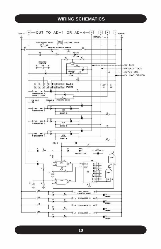
wiRinG scHemAtics
11
REL
AY
REL
AY
REL
AY
REL
AY
REL
AY
REL
AY
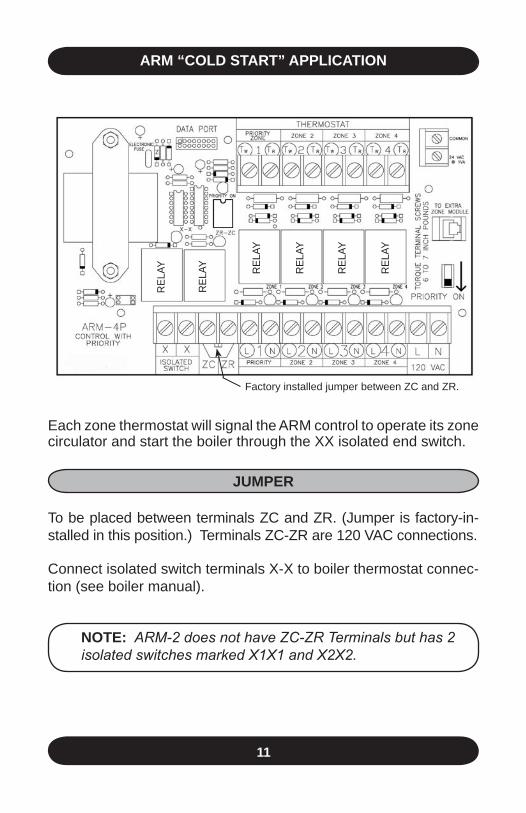
ARm “cOld stARt” ApplicAtiOn
Each zone thermostat will signal the ARM control to operate its zone circulator and start the boiler through the XX isolated end switch.
JumpeR
To be placed between terminals ZC and ZR. (Jumper is factory-in-stalled in this position.) Terminals ZC-ZR are 120 VAC connections.
Connect isolated switch terminals X-X to boiler thermostat connec-tion (see boiler manual).
nOte: ARM-2 does not have ZC-ZR Terminals but has 2 isolated switches marked X1X1 and X2X2.
Factory installed jumper between ZC and ZR.

12
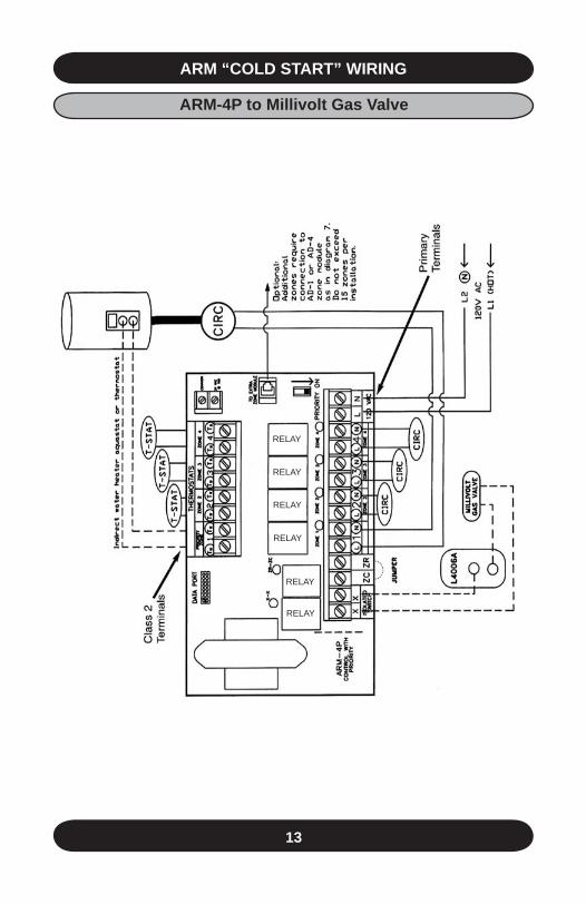
ARm “cOld stARt” wiRinG
Cla
ss 2
Te
rmin
als
Prim
ary
Term
inal
s
RELAY
RELAY
RELAY
RELAY
RELAY
RELAY
ARm-4p to mH l8148
13
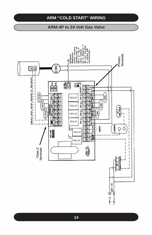
ARm “cOld stARt” wiRinG
RELAY
RELAY
RELAY
RELAY
RELAY
RELAY
ARm-4p to millivolt Gas valve
14
ARm “cOld stARt” wiRinG
RELAY
RELAY
RELAY
RELAY
RELAY
RELAY
ARm-4p to 24 volt Gas valve
15
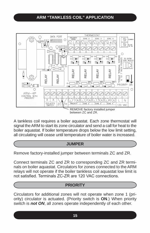
ARm “tAnkless cOil” ApplicAtiOn
REL
AY
REL
AY
REL
AY
REL
AY
REL
AY
REL
AY
REMOVE factory installed jumperbetween ZC and ZR.
A tankless coil requires a boiler aquastat. Each zone thermostat will signal the ARM to start its zone circulator and send a call for heat to the boiler aquastat. If boiler temperature drops below the low limit setting, all circulating will cease until temperature of boiler water is increased.
JumpeR
Remove factory-installed jumper between terminals ZC and ZR.
Connect terminals ZC and ZR to corresponding ZC and ZR termi-nals on boiler aquastat. Circulators for zones connected to the ARM relays will not operate if the boiler tankless coil aquastat low limit is not satisfied. Terminals ZC-ZR are 120 VAC connections.
pRiORitY
Circulators for additional zones will not operate when zone 1 (pri-ority) circulator is actuated. (Priority switch is On.) When priority switch is not ON, all zones operate independently of each other.
16
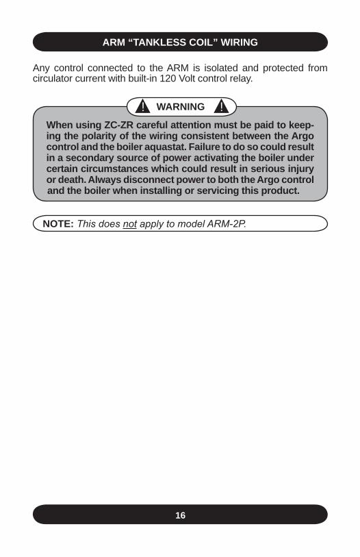
nOte: This does not apply to model ARM-2P.
Any control connected to the ARM is isolated and protected from circulator current with built-in 120 Volt control relay.
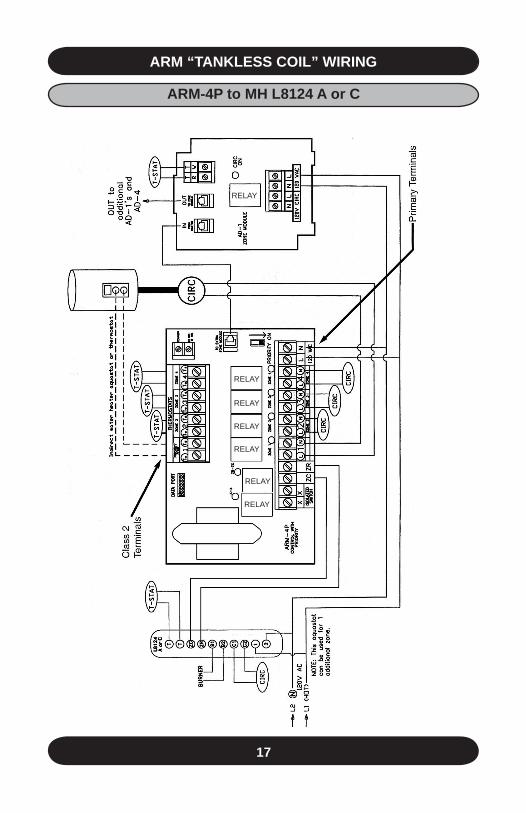
ARm “tAnkless cOil” wiRinG
! ! wARninG
when using Zc-ZR careful attention must be paid to keep-ing the polarity of the wiring consistent between the Argo control and the boiler aquastat. Failure to do so could result in a secondary source of power activating the boiler under certain circumstances which could result in serious injury or death. Always disconnect power to both the Argo control and the boiler when installing or servicing this product.
17
ARm “tAnkless cOil” wiRinG
RELAY
RELAY
RELAY
RELAY
RELAY
RELAY
ARm-4p to mH l8124 A or c
RELAY
18
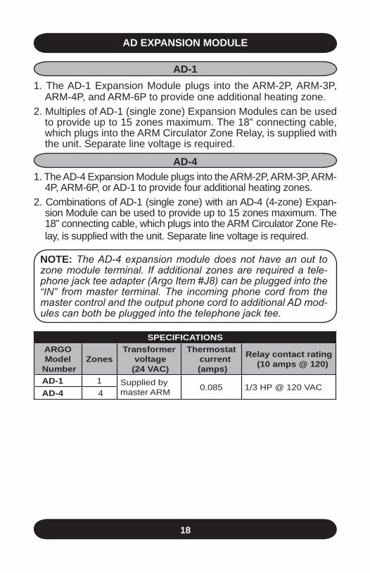
speciFicAtiOnsARGOmodel
number Zones
transformer voltage
(24 vAc)
thermostat current (amps)
Relay contact rating (10 amps @ 120)
Ad-1 1 Supplied by master ARM 0.085 1/3 HP @ 120 VAC
Ad-4 4
Ad expAnsiOn mOdule
Ad-11. The AD-1 Expansion Module plugs into the ARM-2P, ARM-3P,
ARM-4P, and ARM-6P to provide one additional heating zone.2. Multiples of AD-1 (single zone) Expansion Modules can be used
to provide up to 15 zones maximum. The 18” connecting cable, which plugs into the ARM Circulator Zone Relay, is supplied with the unit. Separate line voltage is required.
Ad-41. The AD-4 Expansion Module plugs into the ARM-2P, ARM-3P, ARM-
4P, ARM-6P, or AD-1 to provide four additional heating zones.2. Combinations of AD-1 (single zone) with an AD-4 (4-zone) Expan-
sion Module can be used to provide up to 15 zones maximum. The 18” connecting cable, which plugs into the ARM Circulator Zone Re-lay, is supplied with the unit. Separate line voltage is required.
nOte: The AD-4 expansion module does not have an out to zone module terminal. If additional zones are required a tele-phone jack tee adapter (Argo Item #J8) can be plugged into the “iN” from master terminal. The incoming phone cord from the master control and the output phone cord to additional AD mod-ules can both be plugged into the telephone jack tee.
19
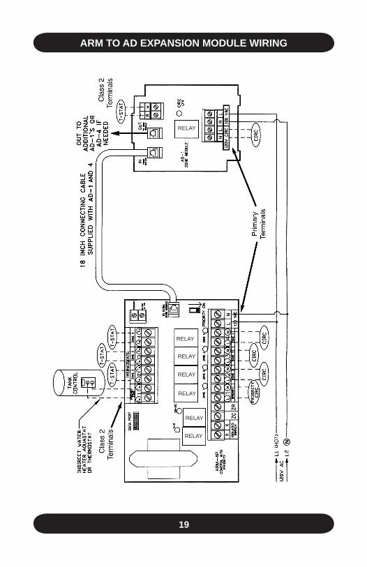
ARm tO Ad expAnsiOn mOdule wiRinG
RELAY
RELAY
RELAY
RELAY
RELAY
RELAY
RELAY
20
RELAY
RELAY
RELAY
RELAY
RELAY
RELAY
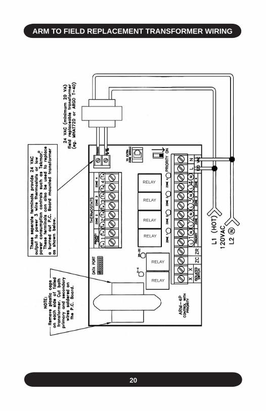
ARm tO Field ReplAcement tRAnsFORmeR wiRinG
21
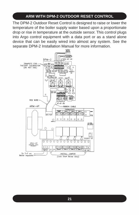
ARm witH dpm-2 OutdOOR Reset cOntROlThe DPM-2 Outdoor Reset Control is designed to raise or lower the temperature of the boiler supply water based upon a proportionate drop or rise in temperature at the outside sensor. This control plugs into Argo control equipment with a data port or as a stand alone device that can be easily wired into almost any system. See the separate DPM-2 Installation Manual for more information.
22
ARm witH /pOweR ROBBinG tHeRmOstAt
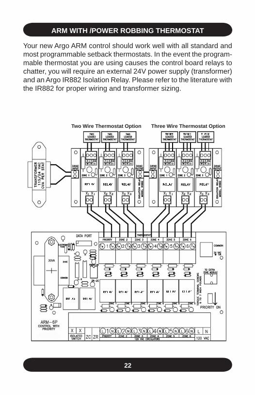
Your new Argo ARM control should work well with all standard and most programmable setback thermostats. In the event the program-mable thermostat you are using causes the control board relays to chatter, you will require an external 24V power supply (transformer) and an Argo IR882 Isolation Relay. Please refer to the literature with the IR882 for proper wiring and transformer sizing.
6
THREE THREE THREE
RELAYRELAYRELAYRELAYRELAY
RELAY RELAY
RELAY RELAY RELAY RELAY RELAY RELAY
two wire thermostat Option three wire thermostat Option
23
part description partnumber
Circulator plug-in relay (24 VAC coil) R35Control plug-in relay (120 VAC coil) (ARM-3, 4, and 6 only) R49
18” Telephone cable connector (connects to AD-1, AD-4) C1
Field-mounted 40 VA transformer (not used on AD-1, or AD-4) T40
Telephone Jack Tee Adapter J8
tecHnicAl suppORt
For technical support on this and all Argo products, please contact ECR International Technical Service at 1-800-325-5479. Please have your model number available when calling.
information needed when calling
Model Number
Installation Date
Installer
ReplAcement pARts

www.argocontrols.com