
INSTALLATION INSTRUCTIONS Arm, Handset & Holder with Hose …
6
B 1 - 6 Trent Thermostatic Two Outlet Concealed Shower Valve , Fixed Shower Arm, Handset & Holder with Hose - TF3S Options: Burlington has a shower head of 3 different sizes for your selection. NOT INCLUDED IN THE BOX Conditions for the use of thermostatic mixing valve The thermostatic valve has been designed to be compliant with the relevant UK standards applicable to this type of product governed by TMV2 standards and WRC. The valve is tested against BS EN 1111. The valve will operate under low pressure but it is recommended that the cold water supply is at least 2 meters from the outlet of the shower valve. • This thermostatic valve is suitable for use with all water systems up to a maximum operating pressure of 5.0 bar, (beyond which we recommend pressure reducing valves to be fitted.) • The valve is provided with two outlets, which are controlled by two flow control cartridges. Commonly used for a main shower head or a flexible shower kit. • An independent, flexible hot and cold water supply pipe is recommended for use to easy maintenance. • If installing a shower pump always install the pump before the shower valve. The list below shows the recommended limits for correct operation; Low Pressure Maximum Static Pressure – Bar 10 Flow Pressure, Hot & Cold - Bar 0.2 to 5 Hot Supply Temperature - °C 55 to 65 Cold Supply Temperature - °C Equal to or less than 25° The British Burns Association recommends 37 to 37.5°C as a comfortable bathing temperature for children. In premises covered by the Care Standards Act 2000, the maximum mixed water outlet temperature of 43°C. Important • We recommend that this product is installed by a qualified professional contractor. Such as a plumber who is certified by NVQ (National Vocational Qualification) or SNVQ (Scottish National Vocational Qualification) Level 3 • Please check this product immediately to ensure that it has not been damaged and is complete. Before installation, please make sure this product is the correct model and you have all the parts required for installation and using. • This valve is a mixing device and therefore requires the water supplies to be reasonably balanced, otherwise we recommend a pressure reducing valve to be fitted. • Please flush the water system to ensure that no metal swarf, solder, and other impurities can enter the valves. • Turn off water supply before commencing work, this should be done at the isolating valves of inlet feeds if fitted or main stopcock. • Please read these instructions carefully and keep it for future reference. INSTALLATION INSTRUCTIONS Options: Burlington has 2 different style handles for your selection, when using these additional handles the indices will need to be utilised from the original handles. Anglesey Birkenhead NOT INCLUDED IN THE BOX
Transcript of INSTALLATION INSTRUCTIONS Arm, Handset & Holder with Hose …

B1 - 6
Trent Thermostatic Two Outlet Concealed Shower Valve , Fixed Shower Arm, Handset & Holder with Hose - TF3S
Options: Burlington has a shower head of 3 different sizes for your selection.
NOT INCLUDED IN THE BOX
Conditions for the use of thermostatic mixing valveThe thermostatic valve has been designed to be compliant with the relevant UK standards applicable to this type of product governedby TMV2 standards and WRC. The valve is tested against BS EN 1111.The valve will operate under low pressure but it is recommended that the cold water supply is at least 2 meters from the outlet of the shower valve.• This thermostatic valve is suitable for use with all water systems up to a maximum operating pressure of 5.0 bar, (beyond which we recommend pressure reducing valves to be fitted.)• The valve is provided with two outlets, which are controlled by two flow control cartridges. Commonly used for a main shower head or a flexible shower kit.• An independent, flexible hot and cold water supply pipe is recommended for use to easy maintenance.• If installing a shower pump always install the pump before the shower valve. The list below shows the recommended limits for correct operation; Low Pressure Maximum Static Pressure – Bar 10 Flow Pressure, Hot & Cold - Bar 0.2 to 5 Hot Supply Temperature - °C 55 to 65 Cold Supply Temperature - °C Equal to or less than 25°
The British Burns Association recommends 37 to 37.5°C as a comfortable bathing temperature for children. In premises covered by the Care Standards Act 2000, the maximum mixed water outlet temperature of 43°C.
Important• We recommend that this product is installed by a qualified professional contractor. Such as a plumber who is certified by NVQ (National Vocational Qualification) or SNVQ (Scottish National Vocational Qualification) Level 3
• Please check this product immediately to ensure that it has not been damaged and is complete. Before installation, please make sure this product is the correct model and you have all the parts required for installation and using. • This valve is a mixing device and therefore requires the water supplies to be reasonably balanced, otherwise we recommend a pressure reducing valve to be fitted. • Please flush the water system to ensure that no metal swarf, solder, and other impurities can enter the valves. • Turn off water supply before commencing work, this should be done at the isolating valves of inlet feeds if fitted or main stopcock.• Please read these instructions carefully and keep it for future reference.
INSTALLATION INSTRUCTIONS
Options: Burlington has 2 different style handles for your selection, when using these additional handles the indices will need to be utilised from the original handles.
Anglesey Birkenhead
NOT INCLUDED IN THE BOX
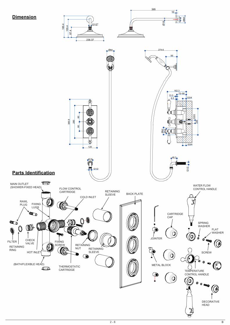
Parts Identification
2 - 6
Dimension
B
RAWL PLUG
FIXING SCREW
BACK PLATE
SCREW
CARTRIDGE CAP
DECORATIVE HEAD
SPRINGWASHER
RETAININGSLEEVE
FLOW CONTROLCARTRIDGE
RETAINING NUT RETAINING
SLEEVE
THERMOSTATICCARTRIDGE
HOT INLET
CHECK VALVE
RETAINING RING
MAIN OUTLET(SHOWER-FIXED HEAD)
COLD INLET
FIXING LUGS
FLATWASHER
TEMPERATURE CONTROL HANDLE
WATER FLOWCONTROL HANDLE
METAL BLOCK
JOINTER
162.3
226
6.5
Ø62
Ø38
G1/2''
236.37
87.4
120
280
8080
385.
9
G1/
2
48.3
395
75~9013.3
G3/
4
Ø18
Ø60
G1/
2"
10
185.
415
5.4
G3/4
G3/4
Ø60
95
274.6
G1/2
42.6
FILTER
(BATH/FLEXIBLE HEAD)
3 - 6 B
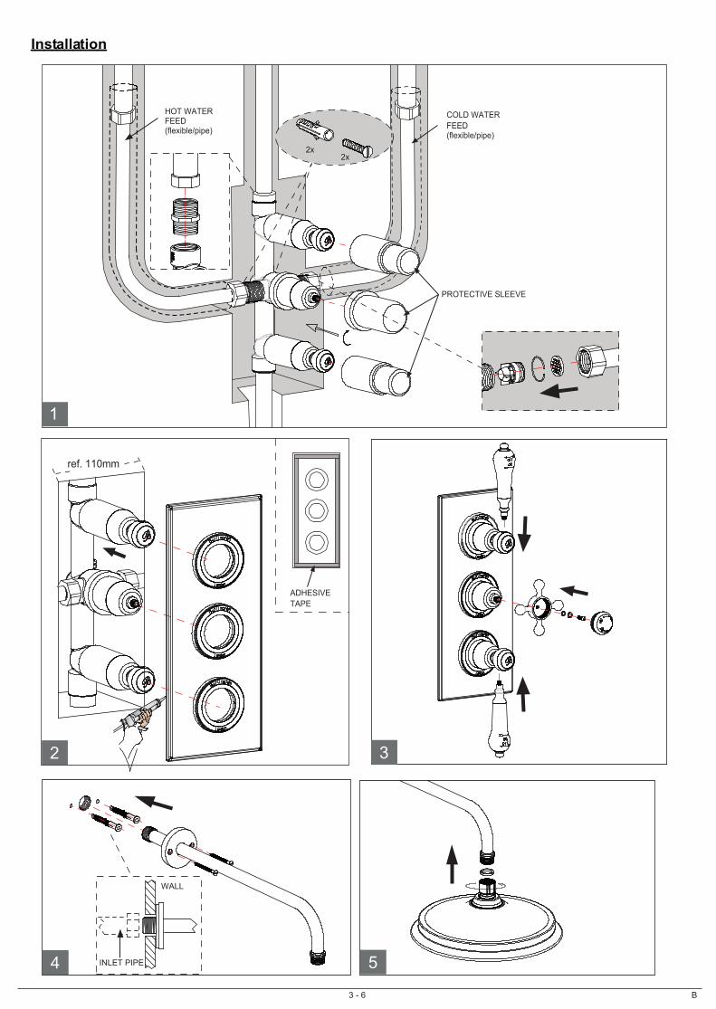
Installation
4 5
WALL
INLET PIPE
1
2x2x
COLD WATERFEED (flexible/pipe)
HOT WATER FEED (flexible/pipe)
PROTECTIVE SLEEVE
2
ref. 110mm
3
ADHESIVETAPE

4 - 6 B
8 9
SHOWER HANDSET
HOSE CONE END
WASHER
HOSENUT END
WASHER
ELBOW
SCREW
SHOWER HOOK
WALL PLUG
6 7
WALL
INLET PIPE
ELBOW
TAIL
The valve should be installed in accordance with the water bye-laws. For further details refer to the latest copy of Water Bye-laws guide or your local water authority. Note: Please check for any hidden pipes and cables before drilling holes in the wall. The fitting of isolation valves is required as close as is practicable to both hot and cold water supply inlets.1. Put the valve (make sure the two protective sleeves are protecting the chrome section) onto the wall and mark the position of the fixing lugs (X2). 2. Make sure the valve is set back from the front face of the wall by the appropriate depth to allow for plasterboard, tiling and filling etc. (min. 75 to max. 90mm)3. Mount the valve to the wall using suitable fixings (see Fig 1). 4. Inlets and outlets are all tapped 3/4”. Make all the pipe work connections using a thread sealer. Don’t use the tapered threaded adaptors.5.Two outlets are recommended for use, one is for a main shower head, the other is for a flexible shower kit. The pipe connection is recommended as the diagram above (see Fig 1). That will be convenient for taking off the valve for easy maintenance.6. Turn on supplies and test all connections for water tightness. (if necessary, the filter and check valve need to be cleaned)7. Then install the plasterboard and tile the wall.8. Remove the adhesive tape film on the backside of back plate. Paste the back plate on the wall. (see Fig 2)9. Apply a narrow bead of silicone sealant around the back edge of the back plate and carefully press into position.10. Mount the handles into position (see Fig 3).11. Install the shower arm on the wall, put the shower head onto the shower arm (see Fig 4 & 5). 12. Connect the elbow with the other outlet (see Fig 6). 13. Seperatelly connect the hose with the shower handset & the elbow (see Fig 7 & 8).14. Make sure the shower hook at a suitable position, fix it onto the wall (see Fig 9).
5 - 6
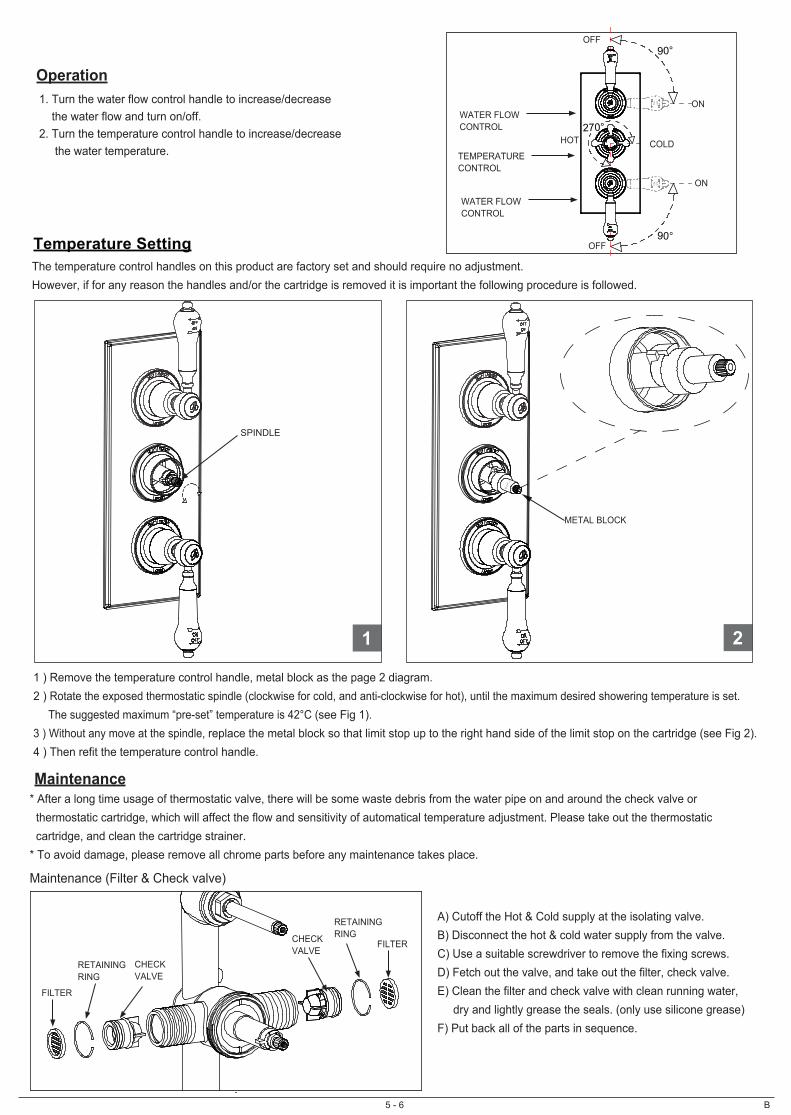
Temperature SettingThe temperature control handles on this product are factory set and should require no adjustment. However, if for any reason the handles and/or the cartridge is removed it is important the following procedure is followed.
1 ) Remove the temperature control handle, metal block as the page 2 diagram.2 ) Rotate the exposed thermostatic spindle (clockwise for cold, and anti-clockwise for hot), until the maximum desired showering temperature is set. The suggested maximum “pre-set” temperature is 42°C (see Fig 1). 3 ) Without any move at the spindle, replace the metal block so that limit stop up to the right hand side of the limit stop on the cartridge (see Fig 2).4 ) Then refit the temperature control handle.
B
1 2
1. Turn the water flow control handle to increase/decrease the water flow and turn on/off.2. Turn the temperature control handle to increase/decrease the water temperature.
Operation
SPINDLE
OFF
ON
TEMPERATURE CONTROL
WATER FLOWCONTROL
Maintenance
A) Cutoff the Hot & Cold supply at the isolating valve. B) Disconnect the hot & cold water supply from the valve.C) Use a suitable screwdriver to remove the fixing screws.D) Fetch out the valve, and take out the filter, check valve.E) Clean the filter and check valve with clean running water, dry and lightly grease the seals. (only use silicone grease)F) Put back all of the parts in sequence.
METAL BLOCK
OFF
ON
OFF
O
N
90°
270°
90°
WATER FLOWCONTROL
HOT COLD
OFF
ON
CHECK VALVE
FILTER
RETAININGRING
FILTER
RETAININGRINGCHECK
VALVE
* After a long time usage of thermostatic valve, there will be some waste debris from the water pipe on and around the check valve or thermostatic cartridge, which will affect the flow and sensitivity of automatical temperature adjustment. Please take out the thermostatic cartridge, and clean the cartridge strainer.* To avoid damage, please remove all chrome parts before any maintenance takes place.
Maintenance (Filter & Check valve)
6 - 6 B
Trouble Shooting1. Output water temperature does not correspond with temperature setCause: Thermostat has not been adjusted base on the existing home water systemRemedy: Adjust the thermostat, refer to “Temperature Setting” procedure.Cause: Hot Water temperature too low.Remedy: Adjuster the water heater, increase hot water temperature to 65°C
2. Crossflow, cold water being forced into hot water pipe, or vice versa, when valve is closedCause: check valves dirty or leaking Remedy: Clean the check valves or exchange if necessary
3. Very low flow or no flowCause: Supply pressure inadequate Remedy: Check hot and cold feeds. If a pump has been installed, please check to see if the pump is working. (the valve will shut down if either the cold or hot water supply fails)
4. Water will not run hot enough when first installed Cause: Wrong maximum temperature setting Remedy: Adjust the maximum temperature, refer to “Temperature Setting” procedure.
Commissioning & Annual TestThe installation of thermostatic mixing valves must comply with the requirement of the Water Supply (Water Fittings) Regulations 1999. TMV2 approve valve must be tested once a year, to check if it is out of the original maximum temperature set. 1. Prepare a calibrated thermometer. 2. Adjust to maximum water temperature. 3. Allow water running 5 seconds for stability, measure the mixed water temperature at the outlet. • The mixed water temperature at the outlet should never exceed 42°C for showers. • The mixed water temperature at the outlet should never exceed 46°C for bath filler.
Note: 46°C is the maximum mixed water temperature from the bath tap. The maximum temperature takes account of the allowable temperature tolerances inherent in thermostatic mixing valves and temperature losses in metal baths. It is not a safe bathing temperature for adults or children. The British Burns Association recommends 37 to 37.5°C as a comfortable bathing temperature for children. In premises covered by the Care Standards Act 2000, the maximum mixed water outlet temperature is 43°C.IF NOT, then the adjustment of the temperature is necessary following the “ Temperature Setting ” 4. Close the isolating valve at the Cold water supply. While the flowing is residual, and the water temperature has no any change obviously from the initial maximum temperatue set. 5. Reopen the Cold supply, retest the water temperature. if also having no change obviously. Then the valve is working correctly, no further service work is required.
CleaningWe do NOT recommend you use any household cleaners to clean the product. Because these cleaners change substance or formula too frequently. So product should be always cleaned only with soapy water and rinsing with clean water and drying with soft cloth.
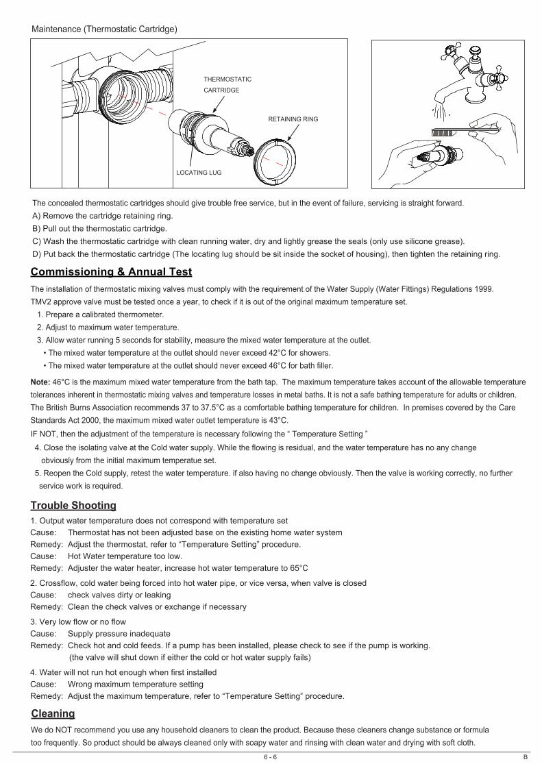
Maintenance (Thermostatic Cartridge)
The concealed thermostatic cartridges should give trouble free service, but in the event of failure, servicing is straight forward. A) Remove the cartridge retaining ring.B) Pull out the thermostatic cartridge.C) Wash the thermostatic cartridge with clean running water, dry and lightly grease the seals (only use silicone grease).D) Put back the thermostatic cartridge (The locating lug should be sit inside the socket of housing), then tighten the retaining ring.
THERMOSTATIC
CARTRIDGE
RETAINING RING
LOCATING LUG