INSTALLATION INSTRUCTIONS SUB – TROLL · PDF fileYour MOOR SUB-TROLL 900 is a precision...
12
1 Your MOOR SUB-TROLL 900 is a precision electronic instrument, which has been designed to simplify your quest for productive fishing sessions. By taking the next 15 minutes and carefully reading these instructions, you will be rewarded with trouble-free service for years to come. Thank you for purchasing this, the finest speed-and- temperature-at-the-lure instrument available. Locate the serial number on the instrument housing and record for future reference. Be sure to fill out and return the enclosed warranty card for your SUB-TROLL 900. Serial No._________________ JUST FOLLOW EIGHT SIMPLE INSTALLATION STEPS: 1. Select a practical location for the instrument head and mount it. 2. Route and connect the 12-volt power supply. 3. Replace existing downrigger cable. 4. Install and connect antenna to the downrigger boom and instrument head. 5. Connect the sending unit and insulate the water connection. 6. Fabricate cannonball leader. 7. Prepare sending unit!! IMPORTANT!! 8. Check power and re-read installation instructions to make sure you have not missed any vital steps. STEP 1. INSTRUMENT HEAD INSTALLATION Locate the instrument head in an area which, during normal trolling activities, will allow you to monitor readings and make appropriate speed and downrigger depth changes. The instrument head MUST be located within the scope of the 25' antenna cable supplied; or else a factory extension must be used. Surface Mounting: 1. Install the pod-mounting bracket on the top surface of the instrument console or on an overhead panel on an enclosed boat, using appropriate screws. 2. Mount the instrument pod to the bracket using the knobs, and placing the star washers between the pod and bracket. 3. After wiring is completed insert instrument into pod so that dial is aligned for viewing. Flush Mounting: (See Figure 1) 1. Select a flat, smooth area on the instrument panel where the instrument can be easily seen. Check for adequate clearance behind the panel. 2. Cut a 4-1/8" diameter hole in the instrument panel at the selected location. 3. Check instrument fit to assure that unit will seat evenly. If necessary, enlarge the hole slightly using a file. INSTALLATION INSTRUCTIONS SUB – TROLL 900
Transcript of INSTALLATION INSTRUCTIONS SUB – TROLL · PDF fileYour MOOR SUB-TROLL 900 is a precision...

1
Your MOOR SUB-TROLL 900 is a precision electronic instrument, which has been designed to simplify your questfor productive fishing sessions. By taking the next 15 minutes and carefully reading these instructions, you will berewarded with trouble-free service for years to come. Thank you for purchasing this, the finest speed-and-temperature-at-the-lure instrument available. Locate the serial number on the instrument housing and record forfuture reference. Be sure to fill out and return the enclosed warranty card for your SUB-TROLL 900.
Serial No._________________
JUST FOLLOW EIGHT SIMPLE INSTALLATION STEPS:
1. Select a practical location for the instrument head and mount it.2. Route and connect the 12-volt power supply.3. Replace existing downrigger cable.4. Install and connect antenna to the downrigger boom and instrument head.5. Connect the sending unit and insulate the water connection.6. Fabricate cannonball leader.7. Prepare sending unit!! IMPORTANT!!8. Check power and re-read installation instructions to make sure you have not missed any vital steps.
STEP 1. INSTRUMENT HEAD INSTALLATION
Locate the instrument head in an area which, during normal trolling activities, will allow you to monitor readingsand make appropriate speed and downrigger depth changes. The instrument head MUST be located within thescope of the 25' antenna cable supplied; or else a factory extension must be used.
Surface Mounting:
1. Install the pod-mounting bracket on the top surface of the instrument console or on an overhead panelon an enclosed boat, using appropriate screws.
2. Mount the instrument pod to the bracket using the knobs, and placing the star washers between the podand bracket.
3. After wiring is completed insert instrument into pod so that dial is aligned for viewing.
Flush Mounting: (See Figure 1)
1. Select a flat, smooth area on the instrument panel where the instrument can be easily seen. Check foradequate clearance behind the panel.
2. Cut a 4-1/8" diameter hole in the instrument panel at the selected location.3. Check instrument fit to assure that unit will seat evenly. If necessary, enlarge the hole slightly using a
file.
INSTALLATION INSTRUCTIONS
SUB – TROLL 900

2
4. Apply sealing compound (i.e.: "Boat-Life" caulk) to the backside of the bezel, and insert the unit intothe hole in an upright position.
5. Place the mounting ring over the back of the unit. Use one self-tapping screw to lock the ring to thecase close to the instrument panel, and use the other three screws to snug the unit to the panel.
Fig. 1 – INSTRUMENT HEAD MOUNTING
STEP 2. CONNECT INSTRUMENT HEAD TO POWER SUPPLY (See Figure 2)
Your MOOR SUB-TROLL 900 requires a 12-volt DC power supply for operation of the instrument head. Thepower draw will be less than 1/4 amp. A fused (1/2 AMP Slow Blow) power cable is included with the unit. Ifadditional wire length is required use 20 gauge or heavier wire. Ideal installation requires leads directly from yourboat's battery to the instrument head. Doing this will minimize ignition interference and noise from engines,generators, pumps, blowers, and other electronics on board. Connect the RED lead of the power cable to the boat'sPositive (+12V) battery terminal. An ON/OFF switch may be added in this line if desired. Connect the BLACKlead of the power cable to both the boat's ground system and the Negative (-) battery terminal. Please re-read thelast sentence again; the electrical current must be returned back to a water ground to complete the circuit. Normallythe water ground is obtained via the engine or out-drive which is common to the negative battery terminal. Plug thepower cable into the power connector on the back of the instrument. If surface mounting, first route the cablethrough the corresponding hole in the surface mount pod.
Note: make sure your boat does not have a positive ground. While this type of grounding system is rare, they areused. If you have this type of grounding the Sub-Troll may not operate properly.
Night Lighting
Your MOOR SUB-TROLL 900 has a night lighting circuit that can be operated by connecting the BLUE wire fromthe back of the instrument head to a +12V DC source. The preferred method is to tap into the positive (+) line of theboat's instrument lighting circuit. It is not recommended to wire the light so that it is on at all times.

3
FIG. 2 – WIRING DIAGRAM
STEP 3. CABLE INSTALLATION
Moor has provided you with 200' of high quality nylon coated downrigger cable for use with the SUB-TROLL 900.It is necessary to use this coated cable to ensure that signals traveling from the sending unit reach the antenna, thusallowing the system to work properly. Remove any existing cable on your downrigger and replace with thatsupplied. During normal operation, portions of this cable may become worn, requiring you to discard the worncable and re-attach the sending unit.Note 1.: It is not necessary to remove worn sections of cable if such conditions are not affecting the performance ofthe unit. However the more exposed metal you have the less depth the unit will work to.Note 2.: If your downrigger have auto stops, see section below.
MAKE SURE YOU FEED THE CABLE THROUGH THE ANTENNA PICK-UP SPRING BEFORE
ATTACHING THE SENDING UNIT.
NOTE: Bare, open, or uninsulated areas of the downrigger cable will result in poor signal reception and lessthan satisfactory operation. The coating on the downrigger cable should be checked periodically forpremature wear. This can be caused by rough edges on the downrigger pulley or housing. Such rough edgesshould be sanded smooth. Also Pay close attention to wire guides on the pulleys, these sometimes haveholes that are about the same size as the wire, with sharp edges. You may have to enlarge this hole orremove wire guide completely. It is also best to run this unit off the back of the boat, not the side. Runningon the side of the boat causes the cable to rub on the side of the pulley.

4
STEP 4. ANTENNA INSTALLATION (See Figure 3)
The antenna is the critical link between the instrument head and the sending unit attached to the downrigger cable.Route the downrigger cable through the antenna pick-up spring. Secure the antenna cable to the downrigger boomso that the spring cannot travel to the spool or the pulley at both extremes. Ty-Wraps are provided for securing thecable to the boom. It is very important that the ty-wraps are placed behind the rubber boot and not on the antennapick up spring. Downriggers that use a bead to stop the cable (Ex. Scotty), see page11.
FIG. 3 ANTENNA INSTALLATION
Plug one end of the extension cable into the antenna cable from the downrigger and route to the instrument head.Plug the other end of the extension cable into the jack on the back of the instrument head. If surface mounting, firstroute the cable through the corresponding hole in the surface mount pod. Keep the cable clear of other antenna andtransducer cables to avoid interaction. Excess cable should be bulked and secured away from any other cables.Additional length extension cables are available direct from Moor.
STEP 5. SENDING UNIT INSTALLATION (See Figure 4a & 4b)
1. Strip (by melting with a match or lighter) approximately 6" of the coating from one end of the
downrigger cable provided. ( VERY IMPORTANT )
2. Slide two crimp sleeves over the bared end of the cable.
3. Feed the stripped downrigger cable around the split thimble andthrough the UPPER EYE of the sending unit. Note: A white dot onthe sending unit body identifies
the UPPER EYE.
4. Adjust the cable so that the insulation starts just above theupper crimp sleeve.
FIG. 4a

5
5. Bend the thimble points together so that the cable smoothly enters and exits the thimble.
6. Holding the wire tightly, slide the crimp sleeves down as close to the thimble as possible and compressthe sleeves using a standard crimping tool. Then trim off the excess bare cable protruding from theupper crimp sleeve. Warning – do not use pliers to crimp the sleeves, this will fan the wires out andcause the cable to fail prematurely.
7. Wrap the connection (including the entire eye) using the water-proof tape supplied, starting at thehousing and covering beyond the crimp sleeves so that no bare metal is exposed.
It is very important that all bare cable, sleeves and the upper eye to which the cable is attached are well insulatedfrom the water. Maintain light tension on the cable when insulating to assure contact between the bare cable,thimble, and eye. Mounting the unit in this way will allow the unit to work to its maxim depth of 200 feet. If yourdownrigger have auto stops, see section below.
Moor also has for purchase a modified version of the Klincher, so crimping sleeves is not needed.
If you elect not to insulate the connection point between the probe and the downrigger cable your unit will stillwork. The depth of operation will very, but the average is around 100 ft. The unit will require the replacement ofthe battery much sooner than when the unit is taped. You can also use a snap swivel so the probe can be removed.But, only use the silver type, the swivels that are black metal or plastic will block the signal coming from the probe.Also using a snap on the upper eye can increase the possibility of losing the probe if the snap fails. Broken snapswivels are not covered under the warranty.
FIG. 4b SENDING UNIT INSTALLATION
IMPORTANT!! FOR BEST OPERATION WRAP TIGHT WITH INSULATING TAPE
PLACE TWO SLEEVES ONTO CABLE.FEED STRIPPED END OF CABLE THRUTHIMBLE, PLACE UPPER EYE OFSENDING UNIT ONTO THIMBLE ANDSQUEEZE ENDS OF THIMBLE TOGETHER.FEED CABLE BACK THRU SLEEVES, PULLTIGHT AND COMPRESS SLEEVES WITHCRIMPING TOOL.
WARNING: USING PLIERS OR EXCESSIVEFORCE ON THE CRIMPER MAY FRACTURETHE CABLE, LIMITING SERVICE LIFE ANDPOSSIBLY CAUSING THE LOSS OF THE
SENDING UNIT.
THREADED
PLUGATTACH
9 VOLT ALKALINE
BATTERY
WHITE DOT
( UP )
ATTACH DOWNRIGGER
WEIGHT
O - RING

6
DOWNRIGGERS WITH AUTO STOP & BEADS ON CABLE
If mounting the Sub-Troll 900 to a downrigger with auto stops, this feature will still work. You must follow theinstructions below for mounting the downrigger cable and probe. This type of hook up is only for rigger that hascurrent sensing to stop unit. Downrigger that has a bead on the cable to stop unit may skip this step, we do have anoptional antenna for these riggers (Scotty & Big John), see page11. Having any type of bead or crimp on thedownrigger cable that passes though the standard antenna will damage it.
1. Remove the existing downrigger cable that is mounting on your downrigger2. From one end of the coated cable remove about 6 feet of coating from the cable. Burning it off with a match
can do this. When you are done clean with cloth and sand paper.3. Mount the end of the cable with the coating removed to the downrigger reel per the manufacture’s
specifications .4. Slowly spool the cable on to the reel making sure that the uncoated cable comes in contact with the lug on the
reel. If the uncoated cable does not make contact with the lug the auto stop will not work. See fig. #5a5. Mount the probe as stated in the instruction above, but you must leave at least ¼ inch of exposed metal at the
base of the eye. See fig. #5b
FIG. #5a FIG. # 5b
NOTE: On Cannon downrigger do not use the black plastic auto stop clip. The probe will take the place of this clip.
Using this clip will block the signal from the probe and the unit will not work properly.
Insulation Considerations
A clean RF signal and satisfactory operation depend on proper insulation. A bare downrigger cable or connectionsreduce the operation depth of the MOOR SUB-TROLL 900. The more exposed metal you have on the downriggercable or connection, the less depth the unit will work to. The upper eye (white dot) on the sending unit is mostcritical as this connection transmits information to your instrument head. The downrigger cable connection may beinsulated using either the waterproof tape provided or using a suitable liquid sealant. Moor has supplied an adequateamount of rubberized tape for your initial installation. The tape that we supply will not make the connectionwatertight, this would be impossible. The tape is just reducing the amount of exposed metal to the water. Hookingthe unit up in this manor will allow the Sub-Troll 900 to work to the full 200 feet. The tape is "Scotch" brand (3M)Liner less Rubber Splicing Tape, Part No. 130C or 2228. Additional supplies may be purchased from a localelectrical supply house. Do not use conventional electrical or friction tape, as they will not maintain a suitablewatertight connection. Acceptable alternate insulating materials are Liquid Electric Tape (available from your localboating supply store), Magic Chem. Corp. Rubber Repair Magic B, 3M Plastic Rubber Tape, and Duco PlasticRubber.
STEP 6. FABRICATE CANNONBALL LEADER
Install an 18" or so uncoated steel leader of approximately 80 lb. test between the LOWER EYE of the sending unitand the downrigger weight. This is necessary because if you happen to snag the bottom, you want the downriggerweight to break loose, saving the sending unit. We suggest you use a cannonball 2 lbs. heavier than normal to holdproper alignment of all riggers and compensate for the additional water resistance. The lower eye is the ground
connection, and should not be taped or coated.

7
STEP 7. PREPARE THE SENDING UNIT (See Figure 4)
Unscrew the threaded plug from the end of the sending unit and withdraw the battery clip. Attach the clip to a 9-volt
alkaline battery. Insert the battery in the unit, with the battery clip facing down. When inserting the batteryroute the wires from the battery clip so that they are secured behind the battery and not left protruding beyond thetop of the battery. If left exposed the wires will be damaged when the plug is installed or cause the probe to leak
NOTE: Extremely cold water and/or a weak battery will give poor results. Use only high-quality, fresh,alkaline batteries in the MOOR SUB-TROLL 900. New batteries have been known to be defective. Shouldoperation not be satisfactory after a battery installation, replace or test the battery.
The sending unit contains an automatic ON/OFF switch so that there will be no need to remove the battery aftereach use; while the unit is immersed in water, it will be ON, and when the unit is dry, it will be OFF.The battery life can very depending on the type of battery used and the temperature that it is used at. The averagelife is about 160 hours of use.
Plug Installation !!! IMPORTANT !!!
FAILURE TO PROPERLY INSTALL THE SEALING PLUG WILL RESULT IN WATER
LEAKING INTO THE SENDING UNIT, AND DAMAGE TO THE INTERNAL CIRCUITRY.
All sending units are pressure tested prior to leaving the factory and should not leak providing the followinginstructions are strictly followed. The battery compartment must remain watertight for the sending unit to work. Itwill stay watertight if you follow these instructions carefully. The O-ring on the plug accomplishes the seal of thebattery compartment. (See Fig. 4) The threads of the plug have no waterproofing capability but are the means bywhich the O-ring receives the proper pressure for sealing. DO NOT use Teflon tape or any form of pipe dope or
sealant on the threads! Using Teflon tape or pipe dope will cause the probe to leak and will void the
warranty.
To seal:
a. Apply a light coating of Vaseline or similar lubricant to the O-ring.
b. Screw the plug completely into the sending unit making sure that the head of the plug is completely downand in direct contact with the end of the sending unit tube.
DO NOT ATTEMPT TO SUBMERSE THE PROBE IF THE PLUG IS NOT COMPLETELY DOWN!If necessary use a wrench or channel locks to fully seat the plug. Once the plug comes in contact withthe top of the tube, stop, tightening it further will only damage the threads.
It is very important to lubricate the O-ring prior to installation of the plug. The seal is achieved by the O-ring beingsqueezed into a gland smaller than the O-ring itself. Failure to lubricate the O-ring can cause it to deform or tearwhen forced into its gland, which will result in a failure of the seal. The lubricant also extends the life of the O-ringby reducing installation friction and preventing dry rot.
The O-ring seal has been designed so that with proper lubrication you should be able to install the plug completelydown by hand. However if after hand tightening, the head of the plug is not completely down and touching thesending unit tube use a wrench to complete the sealing. Once the plug comes in contact with the top of the tube,stop, tightening it further will only damage the threads.
8
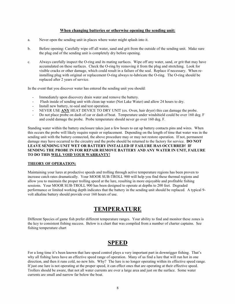
When changing batteries or otherwise opening the sending unit:
a. Never open the sending unit in places where water might splash into it.
b. Before opening: Carefully wipe off all water, sand and grit from the outside of the sending unit. Make surethe plug end of the sending unit is completely dry before opening.
c. Always carefully inspect the O-ring and its mating surfaces. Wipe off any water, sand, or grit that may haveaccumulated on these surfaces. Check the O-ring by removing it from the plug and stretching. Look forvisible cracks or other damage, which could result in a failure of the seal. Replace if necessary. When re-installing plug with original or replacement O-ring always re-lubricate the O-ring. The O-ring should bereplaced after 2 years of service.
In the event that you discover water has entered the sending unit you should:
- Immediately upon discovery drain water and remove the battery.- Flush inside of sending unit with clean tap water (Not Lake Water) and allow 24 hours to dry.- Install new battery, re-seal and test operation.- NEVER USE ANY HEAT DEVICE TO DRY UNIT (ex. Oven, hair dryer) this can damage the probe.- Do not place probe on dash of car or dash of boat. Temperature under windshield could be over 160 deg. F
and could damage the probe. Probe temperature should never go over 160 deg. F.
Standing water within the battery enclosure takes just a few hours to eat up battery contacts pins and wires. Whenthis occurs the probe will likely require repair or replacement. Depending on the length of time that water was in thesending unit with the battery connected, the above procedure may or may not restore operation. If not, permanentdamage may have occurred to the circuitry and the probe should be returned to the factory for service. DO NOT
LEAVE SENDING UNIT WET OR BATTERY INSTALLED IF FAILURE HAS OCCURRED! IF
SENDING THE PROBE IN FOR REPAIR REMOVE BATTERY AND ANY WATER IN UNIT, FAILURE
TO DO THIS WILL VOID YOUR WARRANTY!
THEORY OF OPERATION:
Maintaining your lures at productive speeds and trolling through active temperature regions has been proven toincrease catch rates dramatically. Your MOOR SUB-TROLL 900 will help you find these thermal regions andallow you to maintain the proper trolling speed at the lure, resulting in more enjoyable and profitable fishingsessions. Your MOOR SUB-TROLL 900 has been designed to operate at depths to 200 feet. Degradedperformance or limited working depth indicates that the battery in the sending unit should be replaced. A typical 9-volt alkaline battery should provide over 160 hours of use.
TEMPERATURE
Different Species of game fish prefer different temperature ranges. Your ability to find and monitor these zones isthe key to consistent fishing success. Below is a chart that was compiled from a number of charter captains. Seefishing temperature chart
SPEED
For a long time it’s been known that lure speed control plays a very important part in downrigger fishing. That’swhy all fishing lures have an effective speed range of operation. Many of us find a lure that will run hot in onedirection, and then it runs cold, no new hits. Why? The lure is no longer operating within its effective speed range.If just one lure is not operating at the proper speed, it can effect ones that are operating at their effective speed.Trollers should be aware, that not all water currents are over a large area and just on the surface. Some watercurrents are small and narrow far below the boat.

9
The best way to maintain your lure speed is with the Sub-Troll 900. Once you have the Sub-Troll hooked up, lowerthe probe into the water a few feet below the surface. Make sure that the probe is not in any prop wash or turbulencefrom the boat. Then place the lure you would like to use in the water just below the surface of the water, but makesure you can still see the lure. Then adjust the speed of the boat till the proper action on the lure is obtained. Nowlook at the Sub-Troll display and note the speed, this should be the speed that will give you the best performance outof that lure. You can repeat this for all you lures and set up a chart that show the best speed for each of your lures.Typical troll speeds will be in the range of 1 mph to 3 mph.
CALIBRATION:
The MOOR SUB-TROLL 900 has been factory calibrated for both speed and temperature to be as precise aspossible. However, you may re-calibrate the speed measurement if you feel necessary. The speed calibration screwis accessible through a hole in back of instrument. Using a 1/8" or smaller screwdriver, turn the screw clockwise toincrease the reading, counterclockwise to decrease the reading. DO NOT FORCE THE ADJUSTMENT BEYONDTHE MECHANICAL STOPS! This procedure requires removing the instrument from the surface mount pod if soinstalled.
NEED HELP?
Moor has trained technicians available by phone from 9:00 AM to 4:30 PM (eastern time zone) Monday throughFriday to provide technical assistance.
NEED SERVICE?
Should your instrument become inoperative or if you believe there is a problem with the initial installation, pleasereturn the complete unit to the factory for quick prompt service:
Moor Electronics, Inc. Service Department 95 Dorothy Street Buffalo, NY 14206
Telephone: (716) 821-5304 Fax: (716) 821-5306 Web: WWW.MOORELECTRONICS.COM
Include return address, daytime phone number, description of problem. Send the complete unit back, the display,sending unit (dry without battery attached), antenna and extension cable.
With warranty repairs, proof of purchase date is required. Please enclose proof of purchase date, and $11.00 tocover the cost of return shipping and handling.
With non-warranty repairs you will be advised of the cost upon our inspection of the unit. Payment may be byMaster Card, Visa, check or C.O.D. There is a minimum $20.00 fee for inspecting any unit that is not underwarranty.
PARTS:
05-042-000 Downrigger cable ( 200 ft @ 150lb ) 88-088-010 Probe
05-042-003 Downrigger cable ( 300 ft @ 150lb ) 88-088-020 Antenna 3” Spring ¼ dia.
05-042-210 Downrigger cable ( 300 ft @ 210lb ) 88-088-020S Scotty Antenna ½ dia. tube
10-188-040 25’ Extention cable for antenna 88-088-030 80 lb Leader Kit
14-188-031 Tape # 130C 30’ Roll 88-088-031 Rigger Kit
38-321-150 “O” Ring Seal For Probe 39-055-000 Cover ( face plate )
88-830-150S Turbo blade for ST-900 14-905-006 T-Shirt ST-900 ( M-L-XL)
88-088-032 Klincher mounting kit 31-000-002 Probe holder

10
SUB – TROLL 900 INFORMATION
PROBLEM POSSIBLE CAUSE
UNIT DOES NOT TURN ON
1. Check to see if the display has power, the decimalpoint should light up.
2. The fuse may have burned out
3. Have you applied 12 volts to the power cord?
4. Have you put a 9-volt battery in the probe?
5. You may have a damaged antenna cable
UNIT ONLY WORKS TO 10 FEET,
TEMPERATURE JUMPS OR OSCILATES
1. Are you using the coated cable2. Did you Strip the coating off the cable were it comes
in contact with the rigger kit.3. Do you have the probe mounted with the white dot
up?4. Are you using stainless steel rigger kits? Most black
metal rigger kits will not work. If you use a steelthimble it will rust and unit will fail to operate.
5. You may have a problem with the water ground.6. Have you taped up the connection point on the probe
where the cable attaches to the probe?7. Some other electronics on your boat may be
interfering, turn power off to each, one at a time.8. Did the battery compartment of the probe get wet?9. Have you disabled the shortstops & ion control on
your downrigger10. You may have a bad battery, replace with new11. One of the cables is not plugged all the way in.12. Do you have any thing mounted in line with the
downrigger cable (ex. Release or auto stop clip)
WATER IN PROBE
(AIR DRY ONLY, NEVER HEAT PROBE)
Heating will damage it and void warranty
1. Did you put a light coat of Vaseline on the “o”ring?
2. Is there any foreign materials on the “O” ring(sand, dirt or fibers)
3. If probe gets wet see instructions. Never leavebattery and water inside of the probe. This willdamage it and void warranty.
4. You may have a crack in the tube.
UNIT WORKS FOR ½ HOUR THEN QUITS
1. Battery voltage may be low, replace battery.Some batteries may test good in warmconditions but at low temp’s they will lose theircharge.
TEMPERATURE WORK CORRECTLY BUT
SPEED READS SLOW
1. Voltage to the display readout may be low,must be a min. of 10 volts
Should your instrument become inoperative or if you believe there is a problem with the initial installation, please return the complete unit to thefactory for quick prompt service. When returning the unit include a note, with a return address, daytime phone number and a description of theproblem.
The problems with your unit can be in any one of the components that is needed for operation, this includes wires (don’t send downrigger cable).We would recommend that you send in all parts necessary for the operation of your unit. This will allow our repair department to diagnose thefailure of your unit with greater speed.
If you have any questions please call our service department directly at 716-821-5304. The sales office will only be able to give limitedinformation on repairs
11
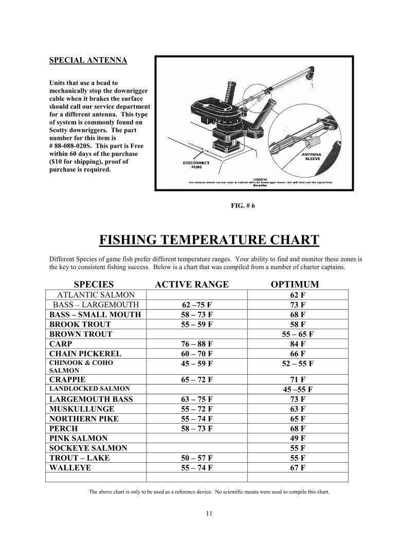
SPECIAL ANTENNA
Units that use a bead to
mechanically stop the downrigger
cable when it brakes the surface
should call our service department
for a different antenna. This type
of system is commonly found on
Scotty downriggers. The part
number for this item is
# 88-088-020S. This part is Free
within 60 days of the purchase
($10 for shipping), proof of
purchase is required.
FIG. # 6
FISHING TEMPERATURE CHART
Different Species of game fish prefer different temperature ranges. Your ability to find and monitor these zones isthe key to consistent fishing success. Below is a chart that was compiled from a number of charter captains.
SPECIES ACTIVE RANGE OPTIMUMATLANTIC SALMON 62 F
BASS – LARGEMOUTH 62 –75 F 73 F
BASS – SMALL MOUTH 58 – 73 F 68 F
BROOK TROUT 55 – 59 F 58 F
BROWN TROUT 55 – 65 F
CARP 76 – 88 F 84 F
CHAIN PICKEREL 60 – 70 F 66 FCHINOOK & COHO
SALMON45 – 59 F 52 – 55 F
CRAPPIE 65 – 72 F 71 FLANDLOCKED SALMON 45 –55 F
LARGEMOUTH BASS 63 – 75 F 73 F
MUSKULLUNGE 55 – 72 F 63 F
NORTHERN PIKE 55 – 74 F 65 F
PERCH 58 – 73 F 68 F
PINK SALMON 49 F
SOCKEYE SALMON 55 F
TROUT – LAKE 50 – 57 F 55 F
WALLEYE 55 – 74 F 67 F
The above chart is only to be used as a reference device. No scientific means were used to compile this chart.

12
NOTES
LURE TYPE SPEED RANGE NOTES
Rev. 07-2008A