INSTALLATION INSTRUCTIONS - acuitybrands.com · Los adaptadores de montaje a ras de Aculux...
2
For best results, use Aculux flangeless adapters with new, unpainted, paper-faced gypsum board only. Use of these adapters with other ceiling materi- als is not recommended. Note: For the best appearance, at minimum a Level 4 drywall finish for textured ceilings and a Level 5 drywall finish for flat ceilings is recommended. In addition, use of a setting-type joint compound such as Sheetrock ® brand Durabond ® is recommended to increase durability and prevent the formation of hairline cracks over time. Note: For adjustable fixtures when ceilings are thicker than 1”, the maximum aiming angle will be limited to less than 40°. At the maximum ceiling thick- ness, aiming angle will be limited to 25°. Installation Steps Step 1. Install Aculux 2" new construction housing and gypsum board ceiling per the instruction sheet shipped with the recessed housing. Confirm the ceiling cutout dimension is 3.00" x 3.00". The fixture aperture must be centered in this cutout to produce a uniform gap between drywall and recessed housing. Step 2. If fixture is adjustable and has been aimed, return aiming angle to the 0° position. Step 3. Remove adjustment or downlight module from fixture by loosening the (4) adjustment screws. Screws must be gradually loosened in an alternating pattern to prevent binding of the module. (see figure 1) Step 4. Disconnect power plug from module by depressing latch and pulling away from mod- ule. Set module aside. Step 5. Fasten the (4) adapter standoffs to the fixture using a screwdriver. (see figure 2) Step 6. Reconnect power plug to module, and secure module to adapter standoffs/fixture via the (4) adjustment screws loosened in step 2. (see figure 3) Step 7. Aculux flangeless adapters contain a high-performance 3M™ adhesive for permanent attachment to the ceiling. The mating drywall surface must be clean and free of dust for maxi- mum adhesion. Using a damp cloth or sponge, wipe the drywall surface where the adapter will be installed to remove any dirt or dust. Step 8. With 3M™ adhesive release liner in place, test fit the flangeless adapter to the Aculux recessed housing and ceiling. Note: The square return of the adapter is to fit between the drywall cutout and the fixture. If necessary, make adjustments to the drywall cutout to ensure correct fit. Step 9. Peel off 3M™ adhesive release liner, line-up parts (per step 8), and firmly press flange- less adapter onto drywall. Hold for at least 5 seconds for a bond to develop. Step 10. Aculux flangeless adapters contain multiple features to promote maximum adhesion of the joint compound to the part. Proceed in applying and feathering multiple thin layers of a setting-type joint compound (such as Sheetrock ® brand Durabond ® ) according to the Level 4 or Level 5 drywall finishing requirements specified. Smooth and/or sand joint compound so the 3/16" flat surface around the inside perimeter of the adapter is barely visible. Step 11. Ensure the paint shield/leveling gauge is installed in the recessed housing. Prime and paint the ceiling. Step 12. Adjust the height of housing LED module per the instruction sheet shipped with the recessed housing. Note that it may be necessary to remove excess paint or joint compound from the inside surface of the flangeless adapter using a utility knife or scraper for correct trim fit. Step 13. Level module and install trim per INSTALLING FINISHING TRIMS section of the instructions that ship with the fixture. FOR FMA2SQ/120 & FMA2SQ/150 NEW CONSTRUCTION FLANGELESS ADAPTERS Product Services Phone (888) 387-2212 1 of 1 1300 S. Wolf Road • Des Plaines, IL 60018 • Phone 800-323-5068 • Visit us at www.acuitybrands.com/aculux ©2018 Acuity Brands Lighting, Inc. Rev 05/18 P4691 INSTALLATION INSTRUCTIONS CEILING THICKNESS COMPATIBILITY Application FMA2SQ/120 Installed FMA2SQ/150 Installed Min. Max. Min. Max. – Flangeless trims in solid ceilings (wood, stone, tile, etc.) 0.86 1.27 1.27 1.68 – Flangeless trims in drywall ceilings 0.83 1.18 1.18 1.59 Aculux FMA2SQ/120 & FMA2SQ/150 flangeless adapters are intended to be used only with Aculux 2" LED new construction housings and correspond- ing flangeless trims. Figure 1 Figure 2 Figure 3 MODULE ADAPTER STANDOFF ADAPTER STANDOFFS LOOSEN (4) SCREWS TO REMOVE MODULE CEILING SURFACE MUST BE CLEAN UNIFORM GAP BETWEEN HOUSING AND CEILING CUTOUT
Transcript of INSTALLATION INSTRUCTIONS - acuitybrands.com · Los adaptadores de montaje a ras de Aculux...

For best results, use Aculux flangeless adapters with new, unpainted, paper-faced gypsum board only. Use of these adapters with other ceiling materi-als is not recommended. Note: For the best appearance, at minimum a Level 4 drywall finish for textured ceilings and a Level 5 drywall finish for flat ceilings is recommended. In addition, use of a setting-type joint compound such as Sheetrock® brand Durabond® is recommended to increase durability and prevent the formation of hairline cracks over time. Note: For adjustable fixtures when ceilings are thicker than 1”, the maximum aiming angle will be limited to less than 40°. At the maximum ceiling thick-ness, aiming angle will be limited to 25°.
Installation StepsStep 1. Install Aculux 2" new construction housing and gypsum board ceiling per the instruction sheet shipped with the recessed housing. Confirm the ceiling cutout dimension is 3.00" x 3.00". The fixture aperture must be centered in this cutout to produce a uniform gap between drywall and recessed housing.
Step 2. If fixture is adjustable and has been aimed, return aiming angle to the 0° position.
Step 3. Remove adjustment or downlight module from fixture by loosening the (4) adjustment screws. Screws must be gradually loosened in an alternating pattern to prevent binding of the module. (see figure 1)
Step 4. Disconnect power plug from module by depressing latch and pulling away from mod-ule. Set module aside.
Step 5. Fasten the (4) adapter standoffs to the fixture using a screwdriver. (see figure 2)
Step 6. Reconnect power plug to module, and secure module to adapter standoffs/fixture via the (4) adjustment screws loosened in step 2. (see figure 3)
Step 7. Aculux flangeless adapters contain a high-performance 3M™ adhesive for permanent attachment to the ceiling. The mating drywall surface must be clean and free of dust for maxi-mum adhesion. Using a damp cloth or sponge, wipe the drywall surface where the adapter will be installed to remove any dirt or dust.
Step 8. With 3M™ adhesive release liner in place, test fit the flangeless adapter to the Aculux recessed housing and ceiling. Note: The square return of the adapter is to fit between the drywall cutout and the fixture. If necessary, make adjustments to the drywall cutout to ensure correct fit.
Step 9. Peel off 3M™ adhesive release liner, line-up parts (per step 8), and firmly press flange-less adapter onto drywall. Hold for at least 5 seconds for a bond to develop.
Step 10. Aculux flangeless adapters contain multiple features to promote maximum adhesion of the joint compound to the part. Proceed in applying and feathering multiple thin layers of a setting-type joint compound (such as Sheetrock® brand Durabond®) according to the Level 4 or Level 5 drywall finishing requirements specified. Smooth and/or sand joint compound so the 3/16" flat surface around the inside perimeter of the adapter is barely visible.
Step 11. Ensure the paint shield/leveling gauge is installed in the recessed housing. Prime and paint the ceiling.
Step 12. Adjust the height of housing LED module per the instruction sheet shipped with the recessed housing. Note that it may be necessary to remove excess paint or joint compound from the inside surface of the flangeless adapter using a utility knife or scraper for correct trim fit.
Step 13. Level module and install trim per INSTALLING FINISHING TRIMS section of the instructions that ship with the fixture.
FOR FMA2SQ/120 & FMA2SQ/150 NEW CONSTRUCTION FLANGELESS ADAPTERS
Product Services Phone (888) 387-2212
1 of 11300 S. Wolf Road • Des Plaines, IL 60018 • Phone 800-323-5068 • Visit us at www.acuitybrands.com/aculux©2018 Acuity Brands Lighting, Inc. Rev 05/18 P4691
INSTALLATION INSTRUCTIONS
CEILING THICKNESS COMPATIBILITY
ApplicationFMA2SQ/120
InstalledFMA2SQ/150
InstalledMin. Max. Min. Max.
– Flangeless trims in solid ceilings (wood, stone, tile, etc.) 0.86 1.27 1.27 1.68– Flangeless trims in drywall ceilings 0.83 1.18 1.18 1.59
Aculux FMA2SQ/120 & FMA2SQ/150 flangeless adapters are intended to be used only with Aculux 2" LED new construction housings and correspond-ing flangeless trims.
Figure 1
Figure 2
Figure 3
MODULE
ADAPTERSTANDOFF
ADAPTERSTANDOFFS
LOOSEN (4) SCREWS TO REMOVE MODULE
CEILING SURFACE MUST BE CLEAN
UNIFORM GAP BETWEEN HOUSING AND CEILING CUTOUT
Para mejores resultados use únicamente los adaptoradores de montaje a ras Aculux con tablayeso con superficie de papel nueva, sin pintar. No se recomienda el uso de estos adaptadores con otros materiales de techos. Nota: Para la mejor apariencia se recomienda por lo menos un acabado de tablayeso de Nivel 4 para techos texturizados y un acabado de tablayeso de Nivel 5 para techos lisos. Además, se recomienda el uso de compuesto para juntas de secado controlado, tal como Durabond® de la marca Sheetrock®,, para incrementar la durabilidad y para prevenir la formación de grietas finas con el tiempo. Nota: Para los accesorios ajustables cuando los techos son más gruesos que 1", el ángulo máximo de orientación estará limitado a menos de 40°. En el espesor máximo del techo, el ángulo de orientación estará limitado a 25°.
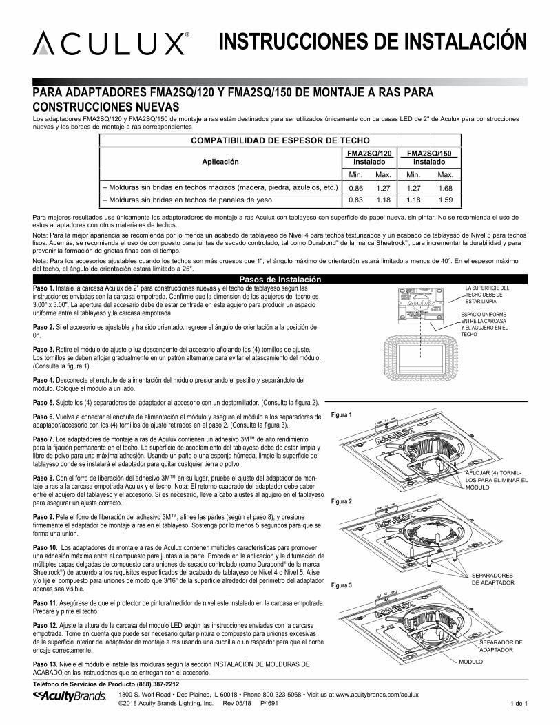
Pasos de InstalaciónPaso 1. Instale la carcasa Aculux de 2" para construcciones nuevas y el techo de tablayeso según las instrucciones enviadas con la carcasa empotrada. Confirme que la dimension de los agujeros del techo es 3.00" x 3.00". La apertura del accesario debe de estar centrada en este agujero para producir un espacio uniforme entre el tablayeso y la carcasa empotrada
Paso 2. Si el accesorio es ajustable y ha sido orientado, regrese el ángulo de orientación a la posición de 0°.
Paso 3. Retire el módulo de ajuste o luz descendente del accesorio aflojando los (4) tornillos de ajuste. Los tornillos se deben aflojar gradualmente en un patrón alternante para evitar el atascamiento del módulo. (Consulte la figura 1).
Paso 4. Desconecte el enchufe de alimentación del módulo presionando el pestillo y separándolo del módulo. Coloque el módulo a un lado.
Paso 5. Sujete los (4) separadores del adaptador al accesorio con un destornillador. (Consulte la figura 2).
Paso 6. Vuelva a conectar el enchufe de alimentación al módulo y asegure el módulo a los separadores del adaptador/accesorio con los (4) tornillos de ajuste retirados en el paso 2. (Consulte la figura 3).
Paso 7. Los adaptadores de montaje a ras de Aculux contienen un adhesivo 3M™ de alto rendimiento para la fijación permanente en el techo. La superficie de acoplamiento del tablayeso debe de estar limpia y libre de polvo para una máxima adhesión. Usando un paño o una esponja húmeda, limpie la superficie del tablayeso donde se instalará el adaptador para quitar cualquier tierra o polvo.
Paso 8. Con el forro de liberación del adhesivo 3M™ en su lugar, pruebe el ajuste del adaptador de mon-taje a ras a la carcasa empotrada Aculux y el techo. Nota: El retorno cuadrado del adaptador debe caber entre el agujero del tablayeso y el accesorio. Si es necesario, lleve a cabo ajustes al agujero en el tablayeso para asegurar un ajuste correcto.
Paso 9. Pele el forro de liberación del adhesivo 3M™, alinee las partes (según el paso 8), y presione firmemente el adaptador de montaje a ras en el tablayeso. Sostenga por lo menos 5 segundos para que se forma una unión.
Paso 10. Los adaptadores de montaje a ras de Aculux contienen múltiples características para promover una adhesión máxima entre el compuesto para juntas a la parte. Proceda en la aplicación y la difumación de múltiples capas delgadas de compuesto para uniones de secado controlado (como Durabond® de la marca Sheetrock®,) de acuerdo a los requisitos especificados del acabado de tablayeso de Nivel 4 o Nivel 5. Alise y/o lije el compuesto para uniones de modo que 3/16" de la superficie alrededor del perímetro del adaptador apenas sea visible.
Paso 11. Asegúrese de que el protector de pintura/medidor de nivel esté instalado en la carcasa empotrada. Prepare y pinte el techo.
Paso 12. Ajuste la altura de la carcasa del módulo LED según las instrucciones enviadas con la carcasa empotrada. Tome en cuenta que puede ser necesario quitar pintura o compuesto para uniones excesivas de la superficie interior del adaptador de montaje a ras usando una cuchilla o un raspador para que el borde encaje correctamente.
Paso 13. Nivele el módulo e instale las molduras según la sección INSTALACIÓN DE MOLDURAS DE ACABADO en las instrucciones que se entregan con el accesorio.
PARA ADAPTADORES FMA2SQ/120 Y FMA2SQ/150 DE MONTAJE A RAS PARA CONSTRUCCIONES NUEVAS
Teléfono de Servicios de Producto (888) 387-2212
1 de 11300 S. Wolf Road • Des Plaines, IL 60018 • Phone 800-323-5068 • Visit us at www.acuitybrands.com/aculux©2018 Acuity Brands Lighting, Inc. Rev 05/18 P4691
INSTRUCCIONES DE INSTALACIÓN
COMPATIBILIDAD DE ESPESOR DE TECHO
AplicaciónFMA2SQ/120
InstaladoFMA2SQ/150
InstaladoMin. Max. Min. Max.
– Molduras sin bridas en techos macizos (madera, piedra, azulejos, etc.) 0.86 1.27 1.27 1.68– Molduras sin bridas en techos de paneles de yeso 0.83 1.18 1.18 1.59
Los adaptadores FMA2SQ/120 y FMA2SQ/150 de montaje a ras están destinados para ser utilizados únicamente con carcasas LED de 2" de Aculux para construcciones nuevas y los bordes de montaje a ras correspondientes
Figura 1
Figura 2
Figura 3
MÓDULO
SEPARADOR DE ADAPTADOR
SEPARADORES DE ADAPTADOR
AFLOJAR (4) TORNIL-LOS PARA ELIMINAR EL MÓDULO
LA SUPERFICIE DEL TECHO DEBE DE ESTAR LIMPIA
ESPACIO UNIFORME ENTRE LA CARCASA Y EL AGUJERO EN EL TECHO