INSTALLATION INSTRUCTIONS - …downloads.chiefmfg.com/MANUALS-I/PAC525P2_PAC526P2... ·...
12
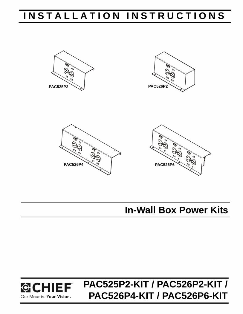
INSTALLATION INSTRUCTIONS PAC525P2 PAC526P2 PAC526P4 PAC526P6 In-Wall Box Power Kits Spanish Product Description German Product Description Portuguese Product Description Italian Product Description Dutch Product Description French Product Description PAC525P2-KIT / PAC526P2-KIT / PAC526P4-KIT / PAC526P6-KIT
Transcript of INSTALLATION INSTRUCTIONS - …downloads.chiefmfg.com/MANUALS-I/PAC525P2_PAC526P2... ·...
I N S T A L L A T I O N I N S T R U C T I O N S
PAC525P2 PAC526P2
PAC526P4 PAC526P6
In-Wall Box Power Kits
Spanish Product DescriptionGerman Product Description
Portuguese Product Description Italian Product DescriptionDutch Product Description
French Product Description
PAC525P2-KIT / PAC526P2-KIT /PAC526P4-KIT / PAC526P6-KIT

PAC525P2-KIT / PAC526P2-KIT / PAC526P4-KIT / PAC526P6-KIT Installation Instructions
2
DISCLAIMER
Milestone AV Technologies, and its affiliated corporations and subsidiaries (collectively, "Milestone"), intend to make this manual accurate and complete. However, Milestone makes no claim that the information contained herein covers all details, conditions or variations, nor does it provide for every possible contingency in connection with the installation or use of this product. The information contained in this document is subject to change without notice or obligation of any kind. Milestone makes no representation of warranty, expressed or implied, regarding the information contained herein. Milestone assumes no responsibility for accuracy, completeness or sufficiency of the information contained in this document.
Chief® is a registered trademark of Milestone AV Technologies. All rights reserved.
IMPORTANT SAFETY INSTRUCTIONS
WARNING alerts you to the possibility of
serious injury or death if you do not follow the instructions.
CAUTION alerts you to the possibility of
damage or destruction of equipment if you do not follow the corresponding instructions.
WARNING: FAILURE TO READ AND
FOLLOW THE FOLLOWING INSTRUCTIONS CAN RESULT IN SERIOUS PERSONAL INJURY, DAMAGE TO EQUIPMENT OR VOIDING OF FACTORY WARRANTY. It is the installer’s responsibility to make sure all components are properly assembled and installed using the instructions provided.
READ ALL INSTRUCTIONS BEFORE USING THIS PRODUCT!!!!
DANGER: TO REDUCE THE RISK OF
ELECTRIC SHOCK:
1. Always turn off power at source before installing the outlet.
WARNING: TO REDUCE THE RISK OF
BURNS, FIRE, ELECTRIC SHOCK, OR INJURY TO
PERSONS:
• Always turn off power at source before servicing or removing the outlet.
• Do not use outdoors - For indoor use only.
• Route cables as shown in these installation instructions.
• To disconnect, turn off power at source.
WARNING: RISK OF ELECTRIC SHOCK!
Make sure the outlet is properly grounded. See Grounding Instructions.
WARNING: Failure to provide adequate
structural strength for this outlet can result in serious personal injury or damage to equipment! It is the installer’s responsibility to make sure the structure to which this product is attached can support the weight of the box.
CAUTION: This equipment must be installed
and assembled by qualified service personnel in accordance with local building and electrical codes.
NOTE: Knockouts are provided for ease of installation. Any unused knockouts that have been punched are to be closed up with a metal plug.
NOTE: Ambient Temperature - The manufacturer’s maximum ambient temperature is 104°F (40°C) and minimum ambient temperature is 30°F (-1°C) so that the installer is able to determine acceptability of use of Accessories and components.
--SAVE THESE INSTRUCTIONS--
Installation Instructions PAC525P2-KIT / PAC526P2-KIT / PAC526P4-KIT / PAC526P6-KIT
3
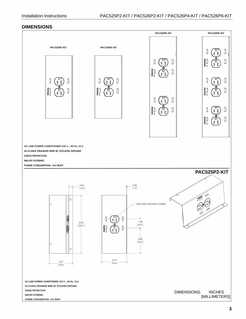
DIMENSIONS
PAC525P2-KIT PAC526P2-KIT
PAC526P4-KIT PAC526P6-KIT
AC LINE POWER CONDITIONER 125 V~, 60 Hz, 15 A
PAC525P2-KIT
DIMENSIONS: INCHES [MILLIMETERS]

PAC525P2-KIT / PAC526P2-KIT / PAC526P4-KIT / PAC526P6-KIT Installation Instructions
4
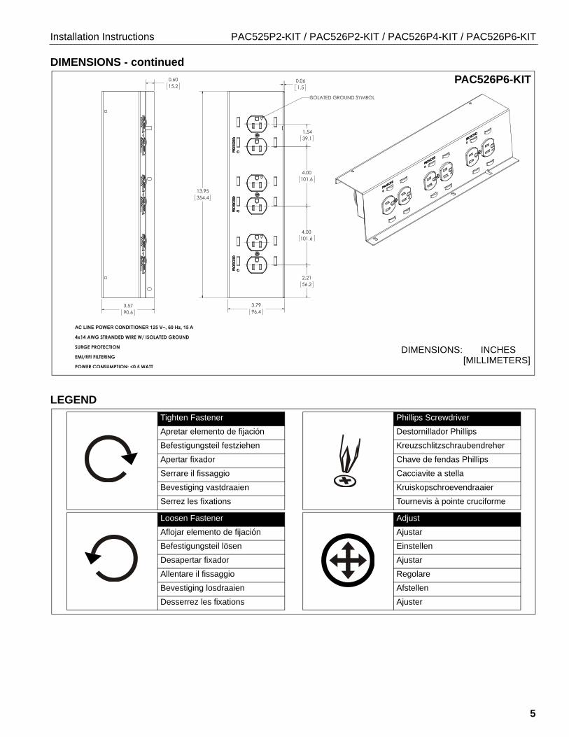
DIMENSIONS - continued
DIMENSIONS: INCHES [MILLIMETERS]
PAC526P4-KIT
PAC526P2-KIT
DIMENSIONS: INCHES [MILLIMETERS]
Installation Instructions PAC525P2-KIT / PAC526P2-KIT / PAC526P4-KIT / PAC526P6-KIT
5
DIMENSIONS - continued
LEGEND
DIMENSIONS: INCHES [MILLIMETERS]
PAC526P6-KIT
Tighten Fastener
Apretar elemento de fijación
Befestigungsteil festziehen
Apertar fixador
Serrare il fissaggio
Bevestiging vastdraaien
Serrez les fixations
Loosen Fastener
Aflojar elemento de fijación
Befestigungsteil lösen
Desapertar fixador
Allentare il fissaggio
Bevestiging losdraaien
Desserrez les fixations
Phillips Screwdriver
Destornillador Phillips
Kreuzschlitzschraubendreher
Chave de fendas Phillips
Cacciavite a stella
Kruiskopschroevendraaier
Tournevis à pointe cruciforme
Adjust
Ajustar
Einstellen
Ajustar
Regolare
Afstellen
Ajuster
PAC525P2-KIT / PAC526P2-KIT / PAC526P4-KIT / PAC526P6-KIT Installation Instructions
6
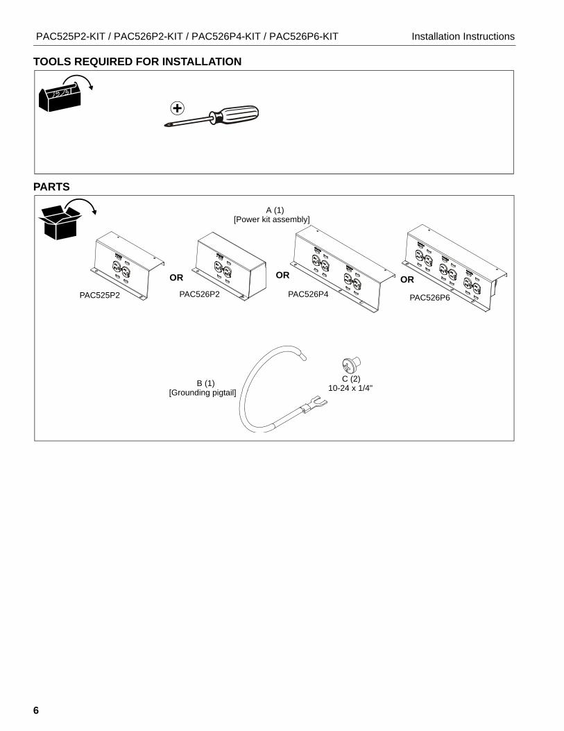
TOOLS REQUIRED FOR INSTALLATION
PARTS
A (1)
PAC525P2 PAC526P2 PAC526P4 PAC526P6
OR OR OR
[Power kit assembly]
B (1)[Grounding pigtail]
C (2)10-24 x 1/4"
Installation Instructions PAC525P2-KIT / PAC526P2-KIT / PAC526P4-KIT / PAC526P6-KIT
7
Isolated Ground Receptacle
This product incorporates an isolated ground receptacle, identified by the orange triangle on its face. This feature may be useful to reduce common noise in the connected equipment. Its intended use is to reduce electrical noise (electromagnetic interference) by purposely insulating the grounding circuit from any metallic wiring system. The ground pin of the receptacle is connected to the green/yellow wire and is isolated from the metal mounting yoke of the receptacle. The accessible metal of the product is connected to the green wire. If it is not desired to use this feature, connect the green/yellow and green wires together.
References
Application Guide for Isolated Ground Wiring Devices 2007, National Electrical Manufacturers Association (NEMA)
IEEE Std 1100™-2005, “IEEE Recommended Practice for Powering and Grounding Electronic Equipment” (Emerald Book), Section 8.5.3.2.
IEEE Std 142™-2007, “IEEE Recommended Practice for Grounding of Industrial and Commercial Power Systems” (Green Book), Sections 5.5.1, 5.5.2
NFPA-70, “National Electrical Code”, Article 250.146 Connecting Receptacle Grounding Terminal to Box.
• (D) Isolated Ground Receptacles. Where installed for the reduction of electrical noise (electromagnetic interference) on the grounding circuit, a receptacle in which the grounding terminal is purposefully insulated from the receptacle mounting means shall be permitted. The receptacle grounding terminal shall be connected to an insulated equipment grounding conductor run with the circuit conductors. This equipment grounding conductor shall be permitted to pass through one or more panel boards without a connection to the panel board grounding terminal bar as permitted in 408.40, Exception, so as to terminate within the same building or structure directly at an equipment grounding conductor terminal of the applicable derived system or service. Where installed in accordance with the provisions of this section, this equipment grounding conductor shall also be permitted to pass through boxes, wire ways, or other enclosures without being connected to such enclosures.
• Informational Note: Use of an isolated equipment grounding conductor does not relieve the requirement for grounding the raceway system and outlet box.
C22.2 No. 1, “Canadian Electrical Code, Part 1”, Rule 10-906 Bonding conductor connection to circuits and equipment.
• (6) A bonding jumper shall be installed to connect the bonding conductor to the grounding terminal of a receptacle and in such a manner that disconnection or removal of the receptacle will not interfere with, or interrupt grounding continuity.
• (7) In the case of metallically enclosed systems where the grounding path is provided by the metal enclosure, a bonding jumper shall be installed to bond the grounding terminal of the receptacle to the enclosure.
• (8) Notwithstanding Sub-rules (6) and (7), the bonding jumper, in the case of receptacles having grounding terminals isolated from the mounting strap required for special equipment, shall be permitted to be extended directly back to the distribution panel.
INSTALLATION
The PAC525P2-/PAC526P2-/PAC526P4-/PAC526P6-KITs are intended for use in the PAC525 and PAC526 Series in-wall boxes.
NOTE: The PAC525P2-, PAC526P2-, PAC526P4-, and PAC526P6-KIT products must be connected to a 15 Amp branch circuit.
WARNING: IMPROPER INSTALLATION CAN RESULT IN DEATH OR SERIOUS PERSONAL INJURY! This accessory should be installed by qualified personnel.
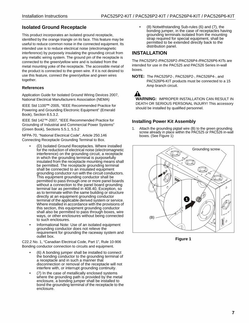
Installing Power Kit Assembly
1. Attach the grounding pigtail wire (B) to the green grounding screw already in place within the PAC525 or PAC526 in-wall boxes. (See Figure 1)
Figure 1
1
Grounding screw
(B)
PAC525P2-KIT / PAC526P2-KIT / PAC526P4-KIT / PAC526P6-KIT Installation Instructions
8
Table 1: Input Specifications
Table 2: Output Specifications
CAUTION: Isolated ground-mounting means NOT grounded. Grounding wire connection required.
IMPORTANT ! : If a separate isolated green/yellow ground wire is installed in the building wiring, attach it separately to the green/yellow isolated ground wire on box. If there is no separate green/yellow isolated ground wire, connect green ground wire to both green/yellow isolated ground wire and green box ground wire on box.
NOTE: The grounding conductors serving this outlet are to be connected to earth ground at the service equipment or other acceptable building earth ground such as the building frame in the case of a high-rise steel-frame structure. Connections should be made with minimum AWG 14 copper wire intended for use on a 15 Amp circuit. The conductors used to connect the outlet to the line or bus and ground shall not be any longer than necessary and shall avoid unnecessary bends.
NOTE: An insulated grounding conductor that is identical in size and insulation material and thickness to the grounded and ungrounded circuit supply conductors, except that it is green with or without one or more yellow stripes, is to be installed as part of the circuit that supplies the outlet. Refer to Table 250-122 of the National Electrical Code regarding the appropriate size of the grounding conductor.
NOTE: Pressure terminal or pressure splicing connectors and soldering lugs used in the installation of the outlet shall be identified as being suitable for the material of the conductors. Conductors of dissimilar metals shall not be intermixed in a terminal or splicing connector where physical contact occurs between dissimilar conductors unless the device is identified for the purpose and conditions of use.
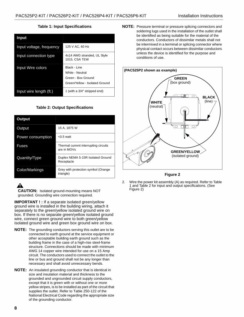
Figure 2
2. Wire the power kit assembly (A) as required. Refer to Table 1 and Table 2 for input and output specifications. (See Figure 2)
Input
Input voltage, frequency 125 V AC, 60 Hz
Input connection type 4x14 AWG stranded, UL Style 1015, CSA TEW
Input Wire colors Black - Line
White - Neutral
Green - Box Ground
Green/Yellow - Isolated Ground
Input wire length (ft.) 1 (with a 3/4" stripped end)
Output
Output 15 A, 1875 W
Power consumption <0.5 watt
Fuses Thermal current interrupting circuits are in MOVs
Quantity/Type Duplex NEMA 5-15R Isolated Ground Receptacle
Color/Markings Grey with protection symbol (Orange triangle)
(PAC525P2 shown as example)
GREEN(box ground)
WHITE(neutral)
BLACK (line)
GREEN/YELLOW (isolated ground)

Installation Instructions PAC525P2-KIT / PAC526P2-KIT / PAC526P4-KIT / PAC526P6-KIT
9
3. Insert the power kit assembly (A) into the in-wall box, joining the tab on the power kit assembly with the tabs in the in-wall box. (See Figure 3)
Figure 3
4. Secure power kit assembly to in-wall box using two 10-24 x 1/4" Phillips pan head screws (C). (See Figure 4)
Figure 4
Outlet Box Use
NOTE: The "PROTECTED" light indicates that the surge protection circuitry is active and operational.
Figure 5
Tab on power kit
(Reverse view)
assembly
In-wallbox tabs
4 (C) x 2
(A)
(PAC525P2 shown as example)
"PROTECTED"indicator light
(PAC525P2 shown as example)

PAC525P2-KIT / PAC526P2-KIT / PAC526P4-KIT / PAC526P6-KIT Installation Instructions
10

Installation Instructions PAC525P2-KIT / PAC526P2-KIT / PAC526P4-KIT / PAC526P6-KIT
11

PAC525P2-KIT / PAC526P2-KIT / PAC526P4-KIT / PAC526P6-KIT Installation Instructions
USA/International A 6436 City West Parkway, Eden Prairie, MN 55344P 800.582.6480 / 952.225.6000F 877.894.6918 / 952.894.6918
Europe A Franklinstraat 14, 6003 DK Weert, NetherlandsP +31 (0) 495 580 852F +31 (0) 495 580 845
Asia Pacific A Office No. 918 on 9/F, Shatin Galleria18-24 Shan Mei Street
Fotan, Shatin, Hong Kong P 852 2145 4099 F 852 2145 4477
Chief, a products division of Milestone AV Technologies
8800-002797 Rev002016 Milestone AV Technologieswww.milestone.com03/16