INSTALLATION INSTRUCTIONS
14
Publications No. Issue Date INSTALLATION INSTRUCTIONS Accessory Application © 2009 American Honda Motor Co., Inc. – All Rights Reserved. AII 42591-42944 (0910) 1 of 14 08V67-SWA-1B00-91 AII 42591-42944 BACK-UP SENSORS 2010 CR-V OCT 2009 PARTS LIST Back-up Sensors Attachment Kit P/N 08V67-SWA-100B Back-up sensor control unit Buzzer Back-up sensor harness Back-up sensor subharness 2 Corner sensor clips Center sensor clips Control unit bracket Connector clip 4 Wire ties 2 Wire ties with clip A Wire tie with clip B Wire tie with clip C 2 EPT sealers Fuse label 2 Self-tapping screws Flange nut Accessory User’s Information Manual Back-up Sensors Kit P/N 08V67-SWA-100J 2 Center sensors 2 Corner sensors (Blue) (STOPPER) (STOPPER) (White)
-
Upload
hondafanatics -
Category
Documents
-
view
119 -
download
9
Transcript of INSTALLATION INSTRUCTIONS

Publications No.
INSTALLATIONINSTRUCTIONS
Accessory Application
© 2009 American Honda Motor Co., Inc. – All Rights Re
AII 42591-42944
BACK-UP SENSORSserved. AII 42591-42944 (0
2010 CR-V
910) 0
Issue Date
OCT 2009
PARTS LISTBack-up Sensors Attachment KitP/N 08V67-SWA-100B
Back-up sensor control unit
Buzzer
Back-up sensor harness
Back-up sensor subharness
2 Corner sensor clips
Center sensor clips
Control unit bracket
Connector clip
4 Wire ties
2 Wire ties with clip A
Wire tie with clip B
Wire tie with clip C
2 EPT sealers
Fuse label
2 Self-tapping screws
Flange nut
Accessory User’sInformation Manual
Back-up Sensors KitP/N 08V67-SWA-100J
2 Center sensors
2 Corner sensors
(Blue)
(STOPPER)
(STOPPER)
(White)
1 of 148V67-SWA-1B00-91
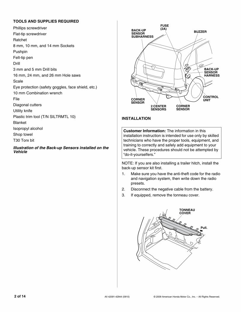
TOOLS AND SUPPLIES REQUIRED
Phillips screwdriverFlat-tip screwdriverRatchet8 mm, 10 mm, and 14 mm SocketsPushpinFelt-tip penDrill3 mm and 5 mm Drill bits16 mm, 24 mm, and 26 mm Hole sawsScaleEye protection (safety goggles, face shield, etc.)10 mm Combination wrenchFileDiagonal cuttersUtility knifePlastic trim tool (T/N SILTRMTL 10)BlanketIsopropyl alcoholShop towelT30 Torx bit
Illustration of the Back-up Sensors installed on the Vehicle
2 of 14 AII 42591-429
INSTALLATION
NOTE: If you are also installing a trailer hitch, install the back-up sensor kit first.1. Make sure you have the anti-theft code for the radio
and navigation system, then write down the radio presets.
2. Disconnect the negative cable from the battery.3. If equipped, remove the tonneau cover.
Customer Information: The information in this installation instruction is intended for use only by skilled technicians who have the proper tools, equipment, and training to correctly and safely add equipment to your vehicle. These procedures should not be attempted by “do-it-yourselfers.”
931903BG
BACK-UP SENSOR SUBHARNESS
CORNER SENSOR
CORNER SENSOR
2 CENTER SENSORS
CONTROL UNIT
BACK-UP SENSOR HARNESS
BUZZER
FUSE (2A)
TONNEAU COVER
Pull.
44 (0910) © 2009 American Honda Motor Co., Inc. – All Rights Reserved.

4. Remove the right rear door sill trim (three clips).
5. Remove the cargo board (two hooks).
6222010B
RIGHT REAR DOOR SILL TRIM
3 CLIPS
FRONT
6410010B
HOOKCARGO BOARD
© 2009 American Honda Motor Co., Inc. – All Rights Reserved. AII 42591-42
6. Remove the weatherstrip from around the rear trim panel. Remove the rear trim panel (two bolts with tie-down hooks, two clips, and four clips).
7. Fold the rear seats forward, and remove the right rear lid from the right cargo area side trim (10 retaining tabs).
8. Remove the vehicle bolt from the right rear trim panel bracket.
6627010B
4 CLIPS
REAR TRIMPANEL
2 CLIPS
2 TIE-DOWNHOOKS
2 BOLTSWEATHERSTRIP
6811060B
RIGHT CARGO AREA SIDE TRIM PANEL
10 RETAINING TABS
RIGHT REAR LID
VEHICLE BOLT
FRONT
RIGHT REAR TRIM PANEL BRACKET
944 (0910) 3 of 14

9. Remove the rear door and tailgate weatherstrip from the right cargo area side trim panel.
10. Remove the right cargo area side trim panel (10 clips).
11. Remove the seat belt from the right quarter pillar glass trim (one cover and one seat belt bolt).NOTE: Torque the seat belt bolt to 32 N·m (24 lbf·ft).
6905060B
8 CLIPS
RIGHT CARGO AREA SIDE TRIM PANELCLIP
FRONT
WEATHERSTRIP
WEATHERSTRIP
6222050B
FRONT
COVER
SEAT BELT
SEAT BELT BOLT
RIGHT QUARTER PILLAR GLASS TRIM
4 of 14 AII 42591-429
12. Remove the right quarter pillar glass trim (seven clips).
13. Remove the left rear splash guard (four self-tapping screws).
14. Remove the right rear splash guard (four self-tapping screws).
6222060B
FRONT
7 CLIPSRIGHT QUARTER PILLAR GLASS TRIM
6620011Y
4 SELF-TAPPING SCREWS
SPLASH GUARD
44 (0910) © 2009 American Honda Motor Co., Inc. – All Rights Reserved.

15. With the help of an assistant, remove the rear bumper (two bolt covers, two bolts, two flange bolts, and two clips). Place the rear bumper on a blanket.
16. If equipped, remove the rear bumper absorber from the rear bumper beam.
920901A
BOLT COVER
CLIP
REAR BUMPER
2 FLANGE BOLTS
REAR BUMPER
2 BUMPER SCREWS
6525560B
REAR BUMPER BEAM
REAR BUMPER ABSORBER
© 2009 American Honda Motor Co., Inc. – All Rights Reserved. AII 42591-42
17. Get the back-up sensor harness. Using isopropyl alcohol on a shop towel, thoroughly clean the area where the fuse label will attach. Attach the (2A BACK-UP SENSOR) label to the fuse case.
18. If the vehicle is equipped with a moonroof, release the moonroof drain hose (two hooks).
6216030B
FUSE LABEL(2A BACK-UP SENSOR)
BACK-UP SENSOR HARNESS
FUSECASE
6509010B
FRONT
MOONROOF DRAIN HOSE
HOOK
944 (0910) 5 of 14

19. Inside the cargo area, remove the clip that secures the vehicle 6-pin connector to the vehicle panel, and unplug the vehicle 6-pin connector.
20. Plug the back-up sensor harness into the vehicle6-pin connector. Plug the other vehicle 6-pin connector into the other back-up sensor harness6-pin connector.
21. Reinstall the vehicle 6-pin connector clip to the vehicle panel.
6311011B
BACK-UP SENSOR HARNESS
FRONT
CLIP
VEHICLE6-PIN CONNECTOR
VEHICLE PANELVEHICLE 6-PIN
CONNECTOR
6-PINCONNECTOR
6-PINCONNECTOR
6311021B
FRONT
CLIP
BACK-UP SENSOR HARNESS
VEHICLE PANEL
VEHICLE 6-PIN CONNECTOR
6 of 14 AII 42591-429
22. Wrap one EPT sealer around to the back-up sensor harness 6-pin connector, and secure the 6-pin connector to the vehicle harness with one wire tie.
23. Using isopropyl alcohol on a shop towel, thoroughly clean the area where the EPT sealer will attach. Attach the EPT sealer to the edge of the vehicle panel in the area shown.
24. Slide the control unit bracket onto the control unit as shown.
980501AB
BACK-UP SENSOR HARNESS
FRONT
BACK-UP SENSOR HARNESS 6-PIN CONNECTOR
WIRE TIEVEHICLE HARNESS
EPT SEALER
VEHICLE PANEL EDGE
EPT SEALER
120 mm
932304AB
CONTROL UNIT
CONTROL UNITBRACKET
44 (0910) © 2009 American Honda Motor Co., Inc. – All Rights Reserved.

25. Plug the back-up sensor harness 14-pin connector into the control unit.
26. Attach the back-up sensor harness clip on the control unit bracket.
27. Insert the stud from the control unit bracket into the hole of the vehicle panel, make sure that the bracket tab is seated in the large hole. Secure the bracket to the vehicle panel using the 6 mm flange nut.
6224060B
CONTROL UNITBRACKET
CONTROL UNIT
BACK-UP SENSOR HARNESS
BACK-UP SENSOR HARNESS CLIP
BACK-UP SENSOR HARNESS 14-PIN CONNECTOR
6311041B
CONTROL UNIT CONTROL UNIT
BRACKET
FRONT HOLE
VEHICLE PANEL 6 mm
FLANGE NUT
STUD
LARGEHOLE
BRACKETTAB
© 2009 American Honda Motor Co., Inc. – All Rights Reserved. AII 42591-42
28. Install the back-up sensor harness clip into the hole in the vehicle panel.
29. Using a utility knife, trim the right quarter pillar glass trim in the area shown.
6224080B
FRONT
BACK-UP SENSOR HARNESS CLIP BACK-UP SENSOR
HARNESS
VEHICLE PANEL
HOLE
932308AB
RIGHT QUARTERPILLAR GLASS TRIM
RIB
5 mm
UTILITY KNIFE
Cut off.
944 (0910) 7 of 14

30. Using a scale and a felt-tip pen, measure and mark the right quarter pillar glass trim in the area shown.
31. Using a pushpin, pierce the two outer marked positions of the right quarter pillar glass trim.
32. While wearing eye protection, drill the two pierced marks to 5 mm. First drill with a 3 mm drill bit, and finish with a 5 mm drill bit.
962502BB
RIGHT QUARTERPILLAR GLASS TRIM
MARKS
FELT-TIP PEN
RIB
RIB
20 mm
22.5 mm6.5 mm
6.5 mmRIB
20 mm
6224101B RIGHT QUARTERPILLAR GLASS TRIM
MARKS
3 mm 5 mm DRILL BIT
DRILLPUSHPIN
8 of 14 AII 42591-4294
33. Using a pushpin, pierce the center marked position of the right quarter pillar glass trim.
34. While wearing eye protection, drill the pierced center mark to 16 mm. First drill with a 3 mm drill bit, and finish with a 16 mm hole saw. Remove any burrs.
35. Using isopropyl alcohol on a shop towel, clean the right quarter pillar glass trim where the double-sided tape will attach. Remove the adhesive backing from the buzzer. Route the buzzer 2-pin connector through the 16 mm hole, and install the buzzer to the right quarter pillar glass trim with the two self-tapping screws. Install with the on/off switch and the volume control toward the front of the vehicle.
36. Reinstall the right quarter pillar glass trim.
963006AB
3 mm DRILL BIT
16 mm HOLE
MARK
DRILL
RIGHT QUARTERPILLAR GLASS TRIM
PUSHPIN
6822011B
RIGHT QUARTERPILLAR GLASS TRIM
2 SELF-TAPPING SCREWS
BUZZER 2-PIN CONNECTOR
5 mmHOLE
DOUBLE-SIDED TAPE
5 mmHOLE
16 mmHOLE
BUZZER
FRONT
SWITCH
VOLUME CONTROL
ADHESIVE BACKING
4 (0910) © 2009 American Honda Motor Co., Inc. – All Rights Reserved.

37. Plug the back-up sensor harness 2-pin connector into the buzzer 2-pin connector.
38. Secure the 2-pin connector:• With a vehicle harness, secure the 2-pin
connector to the vehicle harness with a wire tie.• Without a vehicle harness, secure the 2-pin
connector to the vehicle panel with one wire tie with clip B.
39. Secure the back-up sensor harness to the vehicle harness with one wire tie.
40. Bundle up the excess buzzer harness, and secure it to the vehicle panel with one wire tie with clip C.
962503BB
BUZZER
FRONT VEHICLE PANEL BACK-UP SENSOR
HARNESS 2-PIN CONNECTOR
BUZZER 2-PIN CONNECTOR
VEHICLE HARNESS
WIRE TIE
2-PIN CONNECTOR
2-PIN CONNECTOR
WIRE TIE WITH CLIP B
Without a VehicleHarness
VEHICLEPANEL
972101AD
FRONT
BUZZER
WIRE TIE
BUZZER HARNESSBundle up the excess.
VEHICLE HARNESS BACK-UP
SENSOR HARNESS
WIRE TIE WITH CLIP C
VEHICLE PANEL
© 2009 American Honda Motor Co., Inc. – All Rights Reserved. AII 42591-42
41. At the right rear corner of the vehicle, remove the vehicle grommet.
42. Route the back-up sensor subharness 6-pin connector through the hole where the vehicle grommet was removed, and seat the back-up sensor subharness grommet into the vehicle panel hole.
43. Install the connector clip to the back-up sensorsubharness 6-pin connector.
44. Plug the back-up sensor subharness 6-pin connector into the back-up sensor harness 6-pin connector, and install the connector clip. Secure the clip in the vehicle panel hole in the area shown.
6227010B
FRONT
BACK-UP SENSOR HARNESS 6-PINCONNECTOR
VEHICLE GROMMET(Discard.)
BACK-UP SENSOR SUBHARNESS
BACK-UP SENSOR SUBHARNESS
GROMMET
cargo area outside
VEHICLE PANEL HOLE
6227020B
FRONT
BACK-UP SENSOR SUBHARNESS 6-PIN CONNECTOR
BACK-UP SENSOR HARNESS 6-PIN CONNECTORBACK-UP
SENSOR HARNESS
HOLEVEHICLE PANEL
BACK-UP SENSOR SUBHARNESS 6-PIN CONNECTOR
BACK-UPSENSORSUBHARNESS
CONNECTORCLIP
944 (0910) 9 of 14
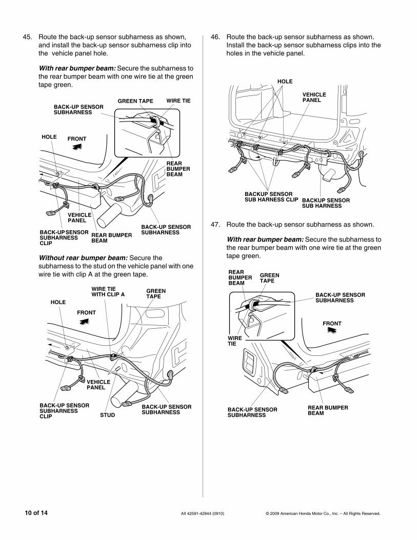
45. Route the back-up sensor subharness as shown, and install the back-up sensor subharness clip into the vehicle panel hole.
With rear bumper beam: Secure the subharness to the rear bumper beam with one wire tie at the green tape green.
Without rear bumper beam: Secure the subharness to the stud on the vehicle panel with one wire tie with clip A at the green tape.
931702AG
FRONT
VEHICLE PANEL
BACK-UP SENSOR SUBHARNESS
BACK-UP SENSOR SUBHARNESS
BACK-UP SENSOR SUBHARNESS CLIP
HOLE
REAR BUMPERBEAM
REAR BUMPER BEAM
GREEN TAPE WIRE TIE
931703AG
FRONT
VEHICLE PANEL
BACK-UP SENSORSUBHARNESS
BACK-UP SENSOR SUBHARNESS CLIP
HOLE
STUD
WIRE TIE WITH CLIP A GREEN
TAPE
10 of 14 AII 42591-429
46. Route the back-up sensor subharness as shown. Install the back-up sensor subharness clips into the holes in the vehicle panel.
47. Route the back-up sensor subharness as shown.
With rear bumper beam: Secure the subharness to the rear bumper beam with one wire tie at the green tape green.
931801AG
VEHICLE PANEL
HOLE
BACKUP SENSOR SUB HARNESS CLIP BACKUP SENSOR
SUB HARNESS
931802AG
FRONT
BACK-UP SENSOR SUBHARNESS
BACK-UP SENSOR SUBHARNESS
REAR BUMPERBEAM
REAR BUMPER BEAM
GREEN TAPE
WIRE TIE
44 (0910) © 2009 American Honda Motor Co., Inc. – All Rights Reserved.
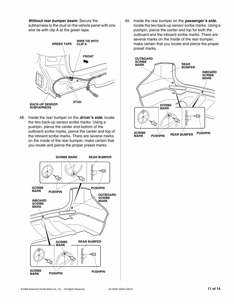
Without rear bumper beam: Secure the subharness to the stud on the vehicle panel with one wire tie with clip A at the green tape.
48. Inside the rear bumper on the driver’s side, locate the two back-up sensor scribe marks. Using a pushpin, pierce the center and bottom of the outboard scribe marks, pierce the center and top of the inboard scribe marks. There are several marks on the inside of the rear bumper; make certain that you locate and pierce the proper preset marks.
931803AG
FRONT
STUD
WIRE TIE WITH CLIP AGREEN TAPE
BACK-UP SENSOR SUBHARNESS
980502AB
REAR BUMPER
PUSHPINSCRIBE MARK
SCRIBE MARK
PUSHPIN
REAR BUMPER
PUSHPINSCRIBE MARK
SCRIBE MARK
PUSHPIN
OUTBOARDSCRIBE MARKINBOARD
SCRIBE MARK
© 2009 American Honda Motor Co., Inc. – All Rights Reserved. AII 42591-42
49. Inside the rear bumper on the passenger’s side, locate the two back-up sensor scribe marks. Using a pushpin, pierce the center and top for both the outboard and the inboard scribe marks. There are several marks on the inside of the rear bumper; make certain that you locate and pierce the proper preset marks.
980503AB REAR BUMPERSCRIBE
MARK
SCRIBE MARK
PUSHPIN
REAR BUMPER
PUSHPIN
OUTBOARDSCRIBE MARK
INBOARDSCRIBE MARK
944 (0910) 11 of 14
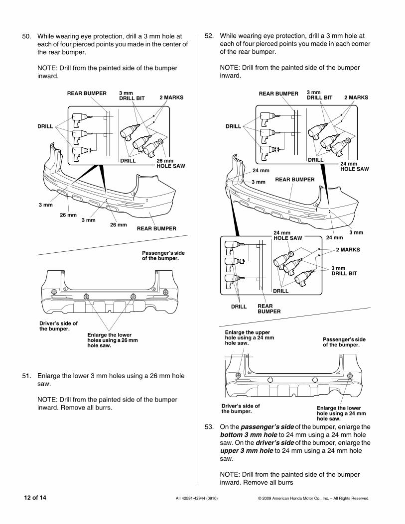
50. While wearing eye protection, drill a 3 mm hole at each of four pierced points you made in the center of the rear bumper.
NOTE: Drill from the painted side of the bumper inward.
51. Enlarge the lower 3 mm holes using a 26 mm hole saw.
NOTE: Drill from the painted side of the bumper inward. Remove all burrs.
931805AG
REAR BUMPER
DRILL
2 MARKS3 mm DRILL BIT
26 mm HOLE SAW
DRILL
REAR BUMPER
3 mm
26 mm3 mm
26 mm
Enlarge the lower holes using a 26 mm hole saw.
Passenger’s side of the bumper.
Driver’s side of the bumper.
12 of 14 AII 42591-429
52. While wearing eye protection, drill a 3 mm hole at each of four pierced points you made in each corner of the rear bumper.
NOTE: Drill from the painted side of the bumper inward.
53. On the passenger’s side of the bumper, enlarge the bottom 3 mm hole to 24 mm using a 24 mm hole saw. On the driver’s side of the bumper, enlarge the upper 3 mm hole to 24 mm using a 24 mm hole saw.
NOTE: Drill from the painted side of the bumper inward. Remove all burrs
932401AG DRILL
DRILL
REAR BUMPER
3 mm DRILL BIT
24 mm HOLE SAW
2 MARKS
REAR BUMPER
DRILL
REAR BUMPER2 MARKS
3 mm DRILL BIT
24 mm HOLE SAW
DRILL
3 mm24 mm
3 mm
24 mm
Enlarge the lower hole using a 24 mm hole saw.
Enlarge the upper hole using a 24 mm hole saw.
Passenger’s side of the bumper.
Driver’s side of the bumper.
44 (0910) © 2009 American Honda Motor Co., Inc. – All Rights Reserved.

54. On the passenger’s side of the rear bumper, install the corner sensor (white) and the center sensor (blue) to the rear bumper using one corner sensor clip, and one center sensor clip. Be sure the sensors are seated properly.
931806AG
REAR BUMPER
REAR BUMPER
CENTER SENSOR CLIP26 mm HOLE
CENTER SENSOR(Blue)
CORNER SENSOR(White)
24 mm HOLE
CORNERSENSOR (White)
CORNER SENSOR CLIP
CENTER SENSOR (Blue)
REAR BUMPER
© 2009 American Honda Motor Co., Inc. – All Rights Reserved. AII 42591-42
55. On the driver’s side of the rear bumper, install the corner sensor (white) and the center sensor (blue) to the rear bumper using one corner sensor clip, and one center sensor clip. Be sure the sensors are seated properly.
931807AG
REAR BUMPER
26 mm HOLE
CENTER SENSOR(Blue)
CENTER SENSOR CLIP
CENTER SENSOR(Blue)
CORNER SENSOR(White)
24 mm HOLE REAR BUMPER
CORNER SENSOR(White)
CORNER SENSORCLIP
944 (0910) 13 of 14
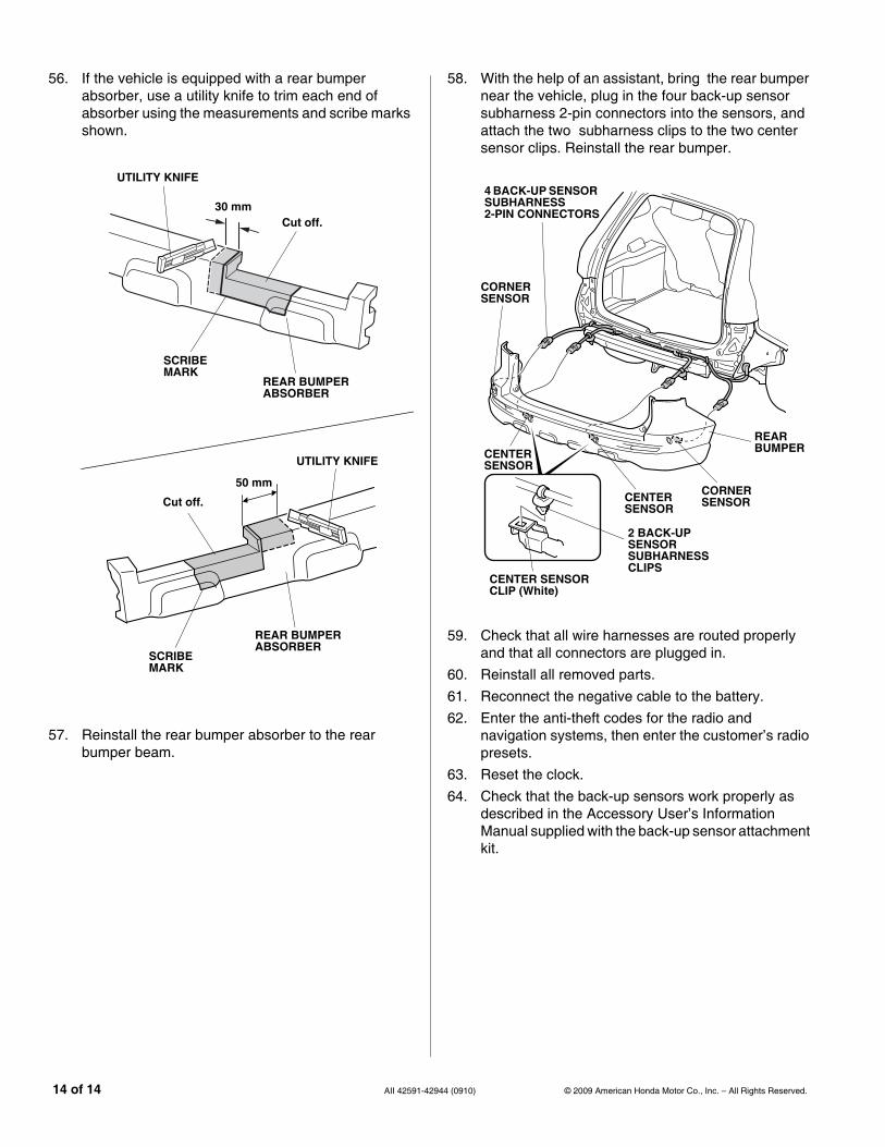
56. If the vehicle is equipped with a rear bumper absorber, use a utility knife to trim each end of absorber using the measurements and scribe marks shown.
57. Reinstall the rear bumper absorber to the rear bumper beam.
931901B
UTILITY KNIFE
Cut off.
SCRIBEMARK
REAR BUMPER ABSORBER
50 mm
UTILITY KNIFE
Cut off.
SCRIBEMARK
REAR BUMPER ABSORBER
30 mm
14 of 14 AII 42591-429
58. With the help of an assistant, bring the rear bumper near the vehicle, plug in the four back-up sensorsubharness 2-pin connectors into the sensors, and attach the two subharness clips to the two center sensor clips. Reinstall the rear bumper.
59. Check that all wire harnesses are routed properly and that all connectors are plugged in.
60. Reinstall all removed parts.61. Reconnect the negative cable to the battery.62. Enter the anti-theft codes for the radio and
navigation systems, then enter the customer’s radio presets.
63. Reset the clock.64. Check that the back-up sensors work properly as
described in the Accessory User’s Information Manual supplied with the back-up sensor attachment kit.
931808AG
REAR BUMPER
CENTER SENSOR
CORNER SENSOR
CORNER SENSOR
4 BACK-UP SENSOR SUBHARNESS 2-PIN CONNECTORS
CENTER SENSOR
CENTER SENSORCLIP (White)
2 BACK-UP SENSOR SUBHARNESS CLIPS
44 (0910) © 2009 American Honda Motor Co., Inc. – All Rights Reserved.