Installation Instructions 06M
8
GENERAL 1. Inspect the compressor for shipping damage and file a claim with the shipping company if damaged or incomplete. 2. Check compressor nameplate for correct model and voltage designation. 3. Before installation, review all Carlyle compressor appli- cation literature to assure yourself that the proper com- pressor has been selected and is being applied in a proper manner. The required application literature is available through Carlyle. Refer to Carlyle Application Guide 574-602. SAFETY INSTRUCTIONS WARNING Failure to follow these instructions could result in serious injury. WARNING Failure to follow these instructions may result in serious injury or death. CONTENTS UNDER PRESSURE. Compressor con- tains oil and refrigerant under pressure. Pressure must be relieved before installation, servicing or opening any connections. HOT and COLD surface temperatures can occur during operation and can result in severe burns or frostbite. USE ONLY approved refrigerants and refrigeration oils. NEVER EXCEED specified test pressures. System strength/tightness test pressure may not exceed the compressor maximum Test pressure on the Nameplate. Close shutoff valves to isolate compressor if necessary. CHECK THE REFRIGERANT TYPE. Charge only with refrigerant that conforms to AHRI Standard 700. Only qualified, authorized, and appropriately trained HVAC or refrigeration personnel, should install, commission, and maintain this equipment. Use appropriate personal safety equipment where required. Safety goggles, gloves, protective clothing, safety boots, and hard hats should be worn where necessary. WARNING Failure to follow these instructions will result in severe personal injury or death. 1. Follow recognized safety procedures and practices. 2. Do not remove any compressor bolts or fittings until factory-supplied holding charge has been relieved. Ex- haust holding charge pressure through low-pressure connection by removing the connection cap and de- pressing the internal disc. See Fig. 1. 3. Do not apply any power to the compressor unless suction and discharge service valves are installed and opened. 4. Do not operate or provide any electrical power to the compressor unless the terminal box cover is in place and secured. Measurement of amps and volts during running conditions must be taken at other points in the power supply. 5. Do not remove terminal box cover until all electrical sources have been disconnected. 6. Follow recommended safety precautions listed on the terminal box cover label before attempting any service work on the compressor. 7. Do not use oxygen or other industrial gases for tight- ness/pressure testing. Use nitrogen or inert gas. Operating limits: Refer to Application Guide 574-602. GENERAL INSTALLATION PROCEDURES Holding Charge Compressor is factory supplied with a 20 psig (2.39 bar) charge of nitrogen. This internal pressure must be relieved before attempting to remove any compressor fitting or part. Relieve holding charge by removing the cap on the low pres- sure connection fitting and depressing the internal disc. See Fig. 1 for applicable low pressure connection fitting location. Service Valves Remove valve pads and attach factory-supplied suction and discharge gaskets and service valves to the compressor. Torque 5 / 16 in. - 18 mounting bolts 16 to 20 ft-lb (21.7 to 27.1 Nm) and 1 / 2 in. - 13 mounting bolts 80 to 90 ft-lb (108.5 to 122 Nm). When brazing piping to valve, disassemble valve or wrap in a wet cloth to prevent heat damage. Oil 1. Check to see that oil level is halfway up on compressor sight glass before starting and after 15 to 20 minutes of operation. Compressors may be shipped with or with- out an oil charge based on model. All compressors must contain the specified oil charge prior to start-up as a condition of warranty. 2. To add oil: Relieve internal crankcase pressure, isolate crankcase, and add oil through the oil fill connection. To remove excess oil: Reduce internal crankcase pres- sure to 2 psig (1.15 bar), isolate crankcase, then loosen the oil drain plug allowing oil to seep out past the threads of the plug. CAUTION With the compressor crankcase under slight pressure, do not remove the oil drain plug as the entire oil charge could be lost. Do not reuse drained oil or oil that has been exposed to the atmosphere. 3. When additional oil or a complete oil change is re- quired, use only the listed Carlyle-approved oils. For refrigerant R-410A and R-744 (subcritical): MANUFACTURER BRAND NAME ICI EMKARATE RL68H CPI Solest 68 CP-2916S *Mobil Arctic EAL 68 *Castrol SW 68 Castrol E 68 Totaline P903-1701, P903-1001 * Only for R-410A: PVE Idemitsu FVC 100D oil is required for all low tem- perature applications when the SST is less than 0°F. Muffler All 06M compressors must have a discharge line muffler in- stalled that is rated for R-410A refrigerant and R-744 CO 2 subcritical. Installation Instructions 06M
Transcript of Installation Instructions 06M

GENERAL1. Inspect the compressor for shipping damage and file a
claim with the shipping company if damaged or incomplete.2. Check compressor nameplate for correct model and
voltage designation.3. Before installation, review all Carlyle compressor appli-
cation literature to assure yourself that the proper com-pressor has been selected and is being applied in a proper manner. The required application literature is available through Carlyle. Refer to Carlyle Application Guide 574-602.
SAFETY INSTRUCTIONS
WARNING
Failure to follow these instructions could result in serious injury.
WARNING
Failure to follow these instructions may result in serious injury or death.CONTENTS UNDER PRESSURE. Compressor con-tains oil and refrigerant under pressure. Pressure must be relieved before installation, servicing or opening any connections.HOT and COLD surface temperatures can occur during operation and can result in severe burns or frostbite.USE ONLY approved refrigerants and refrigeration oils.NEVER EXCEED specified test pressures. System strength/tightness test pressure may not exceed the compressor maximum Test pressure on the Nameplate. Close shutoff valves to isolate compressor if necessary.CHECK THE REFRIGERANT TYPE. Charge only with refrigerant that conforms to AHRI Standard 700.
Only qualified, authorized, and appropriately trained HVAC or refrigeration personnel, should install, commission, and maintain this equipment.Use appropriate personal safety equipment where required. Safety goggles, gloves, protective clothing, safety boots, and hard hats should be worn where necessary.
WARNING
Failure to follow these instructions will result in severe personal injury or death.
1. Follow recognized safety procedures and practices.2. Do not remove any compressor bolts or fittings until
factory-supplied holding charge has been relieved. Ex-haust holding charge pressure through low-pressure connection by removing the connection cap and de-pressing the internal disc. See Fig. 1.
3. Do not apply any power to the compressor unless suction and discharge service valves are installed and opened.
4. Do not operate or provide any electrical power to the compressor unless the terminal box cover is in place and secured. Measurement of amps and volts during running conditions must be taken at other points in the power supply.
5. Do not remove terminal box cover until all electrical sources have been disconnected.
6. Follow recommended safety precautions listed on the terminal box cover label before attempting any service work on the compressor.
7. Do not use oxygen or other industrial gases for tight-ness/pressure testing. Use nitrogen or inert gas.
Operating limits: Refer to Application Guide 574-602.
GENERAL INSTALLATION PROCEDURES
Holding ChargeCompressor is factory supplied with a 20 psig (2.39 bar) charge of nitrogen. This internal pressure must be relieved before attempting to remove any compressor fitting or part.Relieve holding charge by removing the cap on the low pres-sure connection fitting and depressing the internal disc. See Fig. 1 for applicable low pressure connection fitting location.
Service ValvesRemove valve pads and attach factory-supplied suction and discharge gaskets and service valves to the compressor. Torque 5/16 in. - 18 mounting bolts 16 to 20 ft-lb (21.7 to 27.1 Nm) and 1/2 in. - 13 mounting bolts 80 to 90 ft-lb (108.5 to 122 Nm). When brazing piping to valve, disassemble valve or wrap in a wet cloth to prevent heat damage.
Oil1. Check to see that oil level is halfway up on compressor
sight glass before starting and after 15 to 20 minutes of operation. Compressors may be shipped with or with-out an oil charge based on model. All compressors must contain the specified oil charge prior to start-up as a condition of warranty.
2. To add oil: Relieve internal crankcase pressure, isolate crankcase, and add oil through the oil fill connection. To remove excess oil: Reduce internal crankcase pres-sure to 2 psig (1.15 bar), isolate crankcase, then loosen the oil drain plug allowing oil to seep out past the threads of the plug.
CAUTION
With the compressor crankcase under slight pressure, do not remove the oil drain plug as the entire oil charge could be lost. Do not reuse drained oil or oil that has been exposed to the atmosphere.
3. When additional oil or a complete oil change is re-quired, use only the listed Carlyle-approved oils.
For refrigerant R-410A and R-744 (subcritical):
MANUFACTURER BRAND NAMEICI EMKARATE RL68HCPI Solest 68 CP-2916S*Mobil Arctic EAL 68*Castrol SW 68Castrol E 68Totaline P903-1701, P903-1001
* Only for R-410A: PVE Idemitsu FVC 100D oil is required for all low tem-perature applications when the SST is less than 0°F.
MufflerAll 06M compressors must have a discharge line muffler in-stalled that is rated for R-410A refrigerant and R-744 CO2subcritical.
Installation Instructions 06M
2
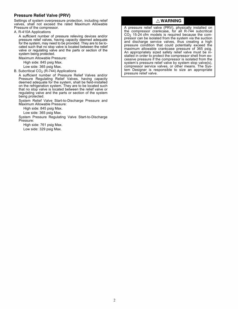
Pressure Relief Valve (PRV)Settings of system overpressure protection, including relief valves, shall not exceed the rated Maximum Allowable Pressure of the compressor. A. R-410A Applications
A sufficient number of pressure relieving devices and/or pressure relief valves, having capacity deemed adequate for the system, may need to be provided. They are to be lo-cated such that no stop valve is located between the relief valve or regulating valve and the parts or section of the system being protected.Maximum Allowable Pressure:
High side: 845 psig Max. Low side: 365 psig Max.
B. Subcritical CO2 (R-744) ApplicationsA sufficient number of Pressure Relief Valves and/or Pressure Regulating Relief Valves, having capacity deemed adequate for the system, shall be field-installed on the refrigeration system. They are to be located such that no stop valve is located between the relief valve or regulating valve and the parts or section of the system being protected.System Relief Valve Start-to-Discharge Pressure and Maximum Allowable Pressure:
High side: 845 psig Max. Low side: 365 psig Max.
System Pressure Regulating Valve Start-to-Discharge Pressure:
High side: 761 psig Max. Low side: 329 psig Max.
WARNING
A pressure relief valve (PRV), physically installed on the compressor crankcase, for all R-744 subcritical CO2 15-24 cfm models is required because the com-pressor can be isolated from the system via the suction and discharge service valves, thus creating a high pressure condition that could potentially exceed the maximum allowable crankcase pressure of 365 psig. An appropriately sized safety relief valve must be in-stalled in order to protect the compressor shell from ex-cessive pressure if the compressor is isolated from the system’s pressure relief valve by system stop valve(s), compressor service valves, or other means. The Sys-tem Designer is responsible to size an appropriate pressure relief valve.
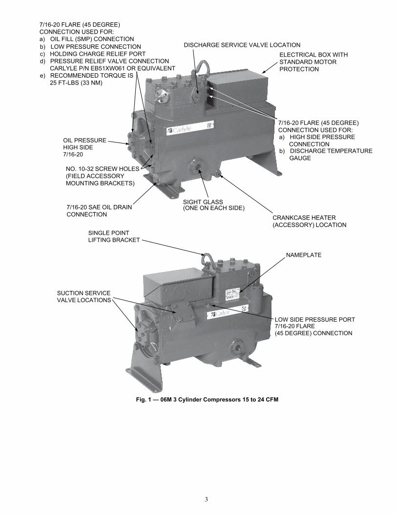
Fig. 1 — 06M 3 Cylinder Compressors 15 to 24 CFM
7/16-20 FLARE (45 DEGREE) CONNECTION USED FOR:a) OIL FILL (SMP) CONNECTIONb) LOW PRESSURE CONNECTIONc) HOLDING CHARGE RELIEF PORTd) PRESSURE RELIEF VALVE CONNECTION CARLYLE P/N EB51XW061 OR EQUIVALENTe) RECOMMENDED TORQUE IS 25 FT-LBS (33 NM)
OIL PRESSUREHIGH SIDE7/16-20
NO. 10-32 SCREW HOLES(FIELD ACCESSORY MOUNTING BRACKETS)
7/16-20 SAE OIL DRAINCONNECTION
7/16-20 FLARE (45 DEGREE) CONNECTION USED FOR:a) HIGH SIDE PRESSURE CONNECTIONb) DISCHARGE TEMPERATURE GAUGE
CRANKCASE HEATER(ACCESSORY) LOCATION
SIGHT GLASS(ONE ON EACH SIDE)
DISCHARGE SERVICE VALVE LOCATIONELECTRICAL BOX WITH STANDARD MOTOR PROTECTION
NAMEPLATE
7/16-20 FLARE(45 DEGREE) CONNECTION
LOW SIDE PRESSURE PORT
SUCTION SERVICEVALVE LOCATIONS
SINGLE POINTLIFTING BRACKET
3

4
ELECTRICAL (06M R-410A)
GeneralConsult the wiring diagram located inside the compressor terminal box cover and Fig. 2 diagram shown below for wir-ing connection locations.
Compressor Circuit ProtectionCompressor circuit protection must be used when applying the 06M compressor. Size appropriate circuit breaker or fuse protection based on local codes. See Carlyle Application Guide 574-602, Section 5.0, ‘Compressor Electrical Data and Motor Protection.’
Compressor Wiring and Motor ProtectionConnect (3) power leads from L1, L2, and L3 to terminals 1, 2, and 3 respectively. See Fig. 2. The motor protection device is factory installed in the 06M electrical box. The motor embedded PTCs (Positive Tempera-ture Coefficient) sensors are factory wired to the motor protec-tion module through terminal plate positions No. 8 and No. 9 (see Fig. 2). The PTC is designed to open if the compressor’s motor temperature exceeds 158F (70 C). The motor is pro-tected against locked rotor, running overload, primary and
secondary single phasing, and loss of refrigerant condition. Control wiring for the motor protection module is applied at positions No. 11, 12, and 14 as shown in Fig. 2. Field wire the protection module supply voltage to terminal positions "L" and "N". Verify supply voltage matches module label voltage; applying an incorrect supply voltage will result in motor protec-tion module failure to function.The compressor's motor protection module is equipped with a set of normally open (NO) and normally closed (NC) contacts. • Terminals 11 and 12 are open during compressor opera-
tion. The contacts will close during a motor over-tem-perature situation and should be used as an alarm output signal to the main controller.
• Terminals 11 and 14 are closed during compression operation. The contacts will open during a motor over-temperature situation, turning the compressor off, pro-vided Terminals 11 and 14 are wired into the compres-sor's start/stop circuitry.
TERMINAL PLATE WIRING1. Customer wiring to the terminal plate must be provided
with ring terminals to accommodate the 1/4 in. - 28 ter-minal studs.
2. Tighten extended terminal nuts to 30 in.-lb (3.4 Nm) maximum.
Fig. 2 — Control Wiring for the Motor Protection Module (06M R-410A)
CUSTOMER WIRING
FACTORY MOTORPROTECTION
CONNECTIONS TERMINAL PLATE
CUSTOMER WIRING (L2)CONNECTION SEE NOTE 5
CUSTOMER WIRING (L3)CONNECTION SEE NOTE 5
CUSTOMER WIRING (L1)CONNECTION SEE NOTE 5
CUSTOMER WIRINGSEE NOTES 2 AND 4
SEE NOTE 3
MOTOR PROTECTIONFACTORY WIRING TO
TERMINAL PLATE POSITIONNO. 8 AND 9
MOTOR PROTECTION
ALARM LAMP
CONTACT COIL
CONTROL
NOTES:1. Do not attempt to remove, inspect or re-install any of the internal parts without referring to service manual.2. Terminals 11 and 12 are normally closed (NC). These contacts are open during normal compressor operation and will close during a motor over temperature situation. Terminals 11 and 14 are normally open (NO). These contacts are closed during normal compression operation and will open during a motor overtemperature situation.3. Factory-installed jumper. Do not remove.4. Supply voltage is 115/230 vac, 24 vac, or 24 vdc. Check motor protection label for correct voltage.5. 1/4-28 terminal studs customer wiring to the terminal plate must be provided with ring terminals to accommodate the 1/4-28 studs. Tighten terminal nuts to 30 in-lbs (3.4 Nm) max (5) places.
FACTORY WIRESTERMINALS 8 AND 9

5
ELECTRICAL: 06M CO2 SUBCRITICAL (R-744)
GeneralConsult the wiring diagram located inside the compressor terminal box cover and Fig. 2 diagram shown below for wir-ing connection locations.
Compressor Wiring and Motor ProtectionConnect (3) power leads from L1, L2, and L3 to terminals 1, 2, and 3, respectively. See Fig. 3. The motor over-current / over-temperature protection device is factory installed in the 06M electrical box. The motor embed-ded PTCs (Positive Temperature Coefficient) are factory wired to the motor protection module through terminal plate positions No. 8 and No. 9 (see Fig. 3). The PTC is designed to open if the compressor’s motor temperature exceeds 158 F (70 C). The motor is protected against locked rotor, running overload, pri-mary and secondary single phasing, and loss of refrigerant con-dition. Control wiring for the motor protection module is applied
at positions No. 11 and 14 as shown in Fig. 3. Field wire the protection module supply voltage to terminal positions "L" and "N". Verify supply voltage matches module label voltage; applying an incorrect supply voltage will result in motor protec-tion module failure to function.The compressor's motor protection module is equipped with a set of normally open (NO) contacts.• Terminals 11 and 14 are closed during compression
operation. The contacts will open during a motor over-temperature or over-current situation, turning the com-pressor off, provided Terminals 11 and 14 are wired into the compressor's start/stop circuitry.
TERMINAL PLATE WIRING1. Customer wiring to the terminal plate must be provided
with ring terminals to accommodate the 1/4 in. - 28 ter-minal studs.
2. Tighten extended terminal nuts to 30 in.-lb (3.4 Nm) maximum.
Fig. 3 — Control Wiring for the Motor Protection Module (R-744)

MODULE
CT COMPRESSOR
TERMINAL PLATE
A. Control Power to the module (Terminals “L” and “N” on the module)B. Module connections for the control circuit (Terminal “11” and “14” on the module)C. Power Lead that is monitored by the CT (Current Transformer) at the terminal plateD. PTC connections at the terminal plate (Terminals “7” and “9” on the compressor)
AB
CD
POWER LEAD THROUGH CT
Fig. 3 — Control Wiring for the Motor Protection Module (R-744) (cont)
6
7
OIL PRESSURE SAFETY SWITCH1. All Carlyle 06M compressors are provided with connec-
tions for an oil safety switch. The use of an oil safety switch can help prevent compressor failures when loss of lubrication or loss of compressor oil change occurs. The use of an oil safety switch is requires as a condi-tion of warranty for those 06M compressors which are applied on systems in which two or more 06M com-pressors are connected in parallel. On units in which single 06M compressors are applied, the use of an oil pressure safety switch is required.
2. Normal oil pressure for 06M compressors is 15 to 45 psi (1.03 to 3.10 bar) above suction pressure. Select a switch to close the control circuit (at start-up) at a maximum of 12 psi (1.84 bar) differential pressure and open the control circuit at a minimum of 8 psi (1.56 bar) differential pres-sure. A time delay of not less than 30 seconds nor more
than 120 seconds is required for start-up purposes. The switch must also be manually reset when it trips.
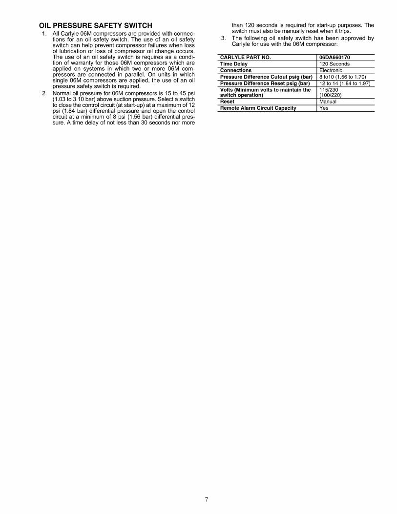
3. The following oil safety switch has been approved by Carlyle for use with the 06M compressor:
CARLYLE PART NO. 06DA660170Time Delay 120 SecondsConnections ElectronicPressure Difference Cutout psig (bar) 8 to10 (1.56 to 1.70)Pressure Difference Reset psig (bar) 12 to 14 (1.84 to 1.97)Volts (Minimum volts to maintain the switch operation)
115/230(100/220)
Reset ManualRemote Alarm Circuit Capacity Yes

CARLYLE COMPRESSOR DIVISION • © CARRIER CORPORATION P.O. Box 4808 • Syracuse, New York 13221Phone 1-800-532-5031 • Fax 1-315-432-3274In U.S. and Puerto Rico: 1-800-GO-CARLYLE (1-800-462-2759)In Canada: 1-800-258-1123In Mexico: 001-800-GO-CARLYLE (001-800-462-2759)
Manufacturer reserves the right to discontinue, or change at any time, specifications or designs and prices without notice and without incurring obligations.
Lit. No. 574-601 (08/12)
(Rev. 8/17)
ITC Classification, U.S. ECCN: EAR99