Installation Gas Dryer D E S IGN Instructions 03 - AJ Madison · personal injury. Always use new...
4
500A420P003 Pub.# 31-16139 Installation Instructions Gas Dryer If you have any questions, call 1-800-GECARES (US) or 1-800-361-3400 (Canada) or Visit our Web site at: www. GEAppliances.com BEFORE YOU BEGIN TOOLS YOU WILL NEED MATERIALS YOU WILL NEED FOR YOUR SAFETY: WARNING • Use only rigid metal or flexible metal 4-in. diameter ductwork for exhausting to the outdoors. Never use plastic or other combustible easy-to-puncture ductwork. • This appliance must be properly grounded and installed as described in these instructions. • Do not install or store appliance in an area where it will be exposed to water and/or weather. • The National Fuel Gas Code restricts installations of gas appliances in garages. They must be 18 in. off the ground and protected by a barrier from vehicles. • Install the dryer where the temperature is above 50ºF for satisfactory operation of the dryer control system. Read these instructions completely and carefully. • IMPORTANT - Save these instructions for local inspector's use. • IMPORTANT - Observe all governing codes and ordinances. • Note to Installer - Be sure to leave these instructions with the customer . • Note to Customer - Keep these instructions with your Use and Care Book for future reference. • This dryer must be exhausted to the outdoors. • Before the old dryer is removed from service or discarded, remove the dryer door . • Service Information and the wiring diagram are located in the control console. • D • Service of this dryer must be performed by a qualified installer,service agency, or the gas supplier. o not allow children on or in the appliance. Close supervision of children is necessary when the appliance is used near children. FLAT BLADE SCREWDRIVER SLIP JOINT PLIERS LEVEL 10" ADJUSTABLE WRENCHES (2) 8" PIPE WRENCH SOAP SOLUTION FOR LEAK DETECTION DUCT TAPE GLOVES SAFETY GLASSES DUCT CLAMPS (2) 4" DIA. METAL ELBOW 4" DIA. METAL DUCT (RECOMMENDED) 4" DIA. FLEXIBLE METAL DUCT (IF NEEDED) EXHAUST HOOD PIPE COMPOUND FLEXIBLE GAS LINE CONNECTOR Step 1 Verify Your Gas Installation (see section 2). Step 2 Prepare the Area and Exhaust for Installation of New Dryer (see section 1). Step 3 Check and Insure the Existing External Exhaust is Clean (see section 1) and Meets Attached Installation Specifications.(see section 6) Step 4 Remove the Foam Shipping Pads (see section 1). Step 5 Move the Dryer to the Desired Location. Step 6 Level Your Dryer (see section 8). Step 7 Connect the Gas Supply (see section 3) and check for leaks (see section 4). Step 8 Connect the External Exhaust (see section 7). Step 9 Connect the Power Supply (see section 5). Step 10 Check the Operation of the Power Supply, Gas Connections, and Venting. Step 11 Place the Owners Manual and the Installation Instructions in a Location Where They Will Be Noticed By the Owner. For Alcove or Closet Installation see section 9. For Bathroom or Bedroom Installation see section 10. For Mobile or Manufactured Home see section 11. In the state of Massachusetts Installation must be performed by a qualified or licensed contractor, plumber, or gasfitter qualified or licensed by the state. D E S I G N C E R T I F I E D 03
-
Upload
vuongxuyen -
Category
Documents
-
view
214 -
download
0
Transcript of Installation Gas Dryer D E S IGN Instructions 03 - AJ Madison · personal injury. Always use new...
500A420P003 Pub.# 31-16139
InstallationInstructions
Gas Dryer
If you have any questions, call 1-800-GECARES (US) or 1-800-361-3400 (Canada)or Visit our Web site at: www. GEAppliances.com
BEFORE YOU BEGIN
TOOLS YOU WILL NEED MATERIALS YOU WILL NEED
FOR YOUR SAFETY:
WARNING• Use only rigid metal or flexible metal 4-in. diameter ductwork for exhausting to the outdoors. Never use plastic or other combustible easy-to-puncture ductwork.• This appliance must be properly grounded and installed as described in these instructions.• Do not install or store appliance in an area where it will be exposed to water and/or weather.• The National Fuel Gas Code restricts installations of gas appliances in garages. They must be 18 in. off the ground and protected by a barrier from vehicles.• Install the dryer where the temperature is above 50ºF for satisfactory operation of the dryer control system.
Read these instructions completely and carefully.
• IMPORTANT - Save these instructions for local inspector's use.
• IMPORTANT - Observe all governing codes and ordinances.• Note to Installer - Be sure to leave these instructions with the customer. • Note to Customer - Keep these instructions with your Use and Care Book for future reference.• This dryer must be exhausted to the outdoors.• Before the old dryer is removed from service or discarded, remove the dryer door.• Service Information and the wiring diagram are located in the control console.
• D
• Service of this dryer must be performed by a qualified installer,service agency, or the gas supplier.
o not allow children on or in the appliance. Close supervision of children is necessary when the appliance is used near children.
FLAT BLADE SCREWDRIVER
SLIP JOINT PLIERS
LEVEL
10" ADJUSTABLE WRENCHES (2)
8" PIPE WRENCH
SOAP SOLUTIONFOR LEAK DETECTION
DUCT TAPEGLOVES SAFETY GLASSES
DUCTCLAMPS (2)
4" DIA. METAL ELBOW 4" DIA. METAL DUCT(RECOMMENDED)
4" DIA. FLEXIBLE METAL DUCT(IF NEEDED) EXHAUST HOOD
PIPE COMPOUND
FLEXIBLE GAS LINE CONNECTOR
Step 1 Verify Your Gas Installation (see section 2).Step 2 Prepare the Area and Exhaust for Installation of
New Dryer (see section 1).Step 3 Check and Insure the Existing External Exhaust is
Clean (see section 1) and Meets Attached InstallationSpecifications.(see section 6)
Step 4 Remove the Foam Shipping Pads (see section 1).Step 5 Move the Dryer to the Desired Location.Step 6 Level Your Dryer (see section 8).Step 7 Connect the Gas Supply (see section 3) and check
for leaks (see section 4).
Step 8 Connect the External Exhaust (see section 7).Step 9 Connect the Power Supply (see section 5).Step 10 Check the Operation of the Power Supply, Gas
Connections, and Venting.Step 11 Place the Owners Manual and the Installation
Instructions in a Location Where They Will BeNoticed By the Owner.
For Alcove or Closet Installation see section 9. For Bathroom or Bedroom Installation see section 10. For Mobile or Manufactured Home see section 11.
In the state of MassachusettsInstallation must be performed by a qualified or licensed contractor, plumber, or gasfitter qualified orlicensed by the state.
DESIGN
CERTIFIED03

Installation Instructions
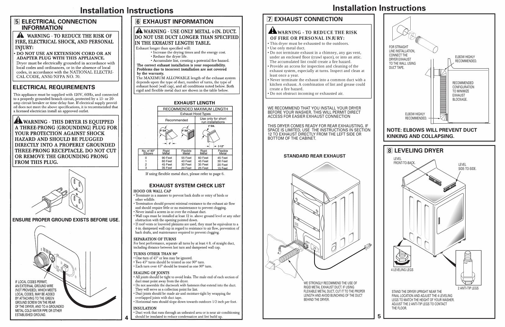
1 PREPARING FOR INSTALLATION OF NEW DRYER
Minimum Clearance Other Than Alcove or Closet InstallationMinimum clearance to combustible surfaces and for air opening are: 0 in. clearance both sides and 1 in. rear. Consideration must be given to provide adequate clearance for proper operation and service.
2 GAS REQUIREMENTS
EXTERNALDUCTOPENING
GASINLETPIPE
CSA (AGA) APPROVEDNEW FLEXIBLE GASLINE CONNECTOR
DUCTTAPE
DUCTTAPE
4" METAL DUCT
TIP: Install your dryer before installing your washer.This will allow better access when installing dryer exhaust.
DISCONNECTING GAS
TURN GASSHUT-OFFVALVE TO THEOFF POSITION.
DISCONNECT AND DISCARD OLDFLEXIBLE GAS CONNECTORAND OLD DUCTING MATERIAL.
The use of old flexible connectors can cause leaks and personal injury. Always use new flexible connectors when installing gas appliances.
WARNING
INTERNAL DUCTOPENING
WARNING - NEVER REUSE OLDFLEXIBLE CONNECTORS.
REMOVING LINT FROM WALLEXHAUST OPENING
CHECK THAT EXHAUSTHOOD DAMPER OPENSAND CLOSES FREELY.
WALL
2
TILT THE DRYER SIDEWAYSAND REMOVE THE FOAMSHIPPING PADS BYPULLING AT THE SIDES AND BREAKING THEMAWAY FROM THE DRYERLEGS. BE SURE TOREMOVE ALL OF THEFOAM PIECES AROUNDTHE LEGS.
• Installation must conform to local codes and ordinances, or in their absence, the NATIONAL FUEL GAS CODE, ANSI Z223.
• This gas dryer is equipped with a Valve & Burner Assem-bly for use only with natural gas. Using conversion kit WE25X0217, your local service organization can convert this dryer for use with propane (LP) gas. ALL CONVER-SIONS MUST BE MADE BY PROPERLY TRAINED AND QUALIFIED PERSONNEL AND IN AC-CORDANCE WITH LOCAL CODES AND ORDI-NANCE REQUIREMENTS.
• The dryer must be disconnected from the gas supplypiping system during any pressure testing of that system at a test pressure in excess of 0.5 PSI (3.4 KPa).
• The dryer must be isolated from the gas supply piping system by closing the equipment shut-off valve during any pressure testing of the gas supply piping of testpressure equal to or less than 0.5 PSI (3.4KPa).
WARNING
DRYER GAS SUPPLY CONNECTION
2"
2-5/8" 3/8" NPT MALE THREAD GAS SUPPLY
NOTE: Add to vertical dimensionthe distance between cabinetbottom to floor.
GAS SUPPLY• A 1/8-in. National Pipe Taper thread plugged tapping, ac-
cessible for test gauge connection, must be installed imme-diately upstream of the gas supply connection to the dryer. Contact your local gas utility should you have questions on the installation of the plugged tapping.
• Supply line is to be 1
• You must use with this dryer a flexible metal connector listed
/2-in. rigid pipe and equipped with an accessible shut-off within 6 ft. of, and in the same room
with, the dryer. • Use pipe thread sealer compound or Teflon tape
appropriate for natural or LP gas.
connector ANSI Z21.24 / CSA 6.10. The length of theconnect shall not exceed 3 ft.
• Connect flexible metal connector to dryer and gas supply.• Open shut-off valve.
6
9 ALCOVE OR CLOSET INSTALLATION
10 BATHROOM OR BEDROOMINSTALLATION
11 MOBILE OR MANUFACTUREDHOME INSTALLATION
Installation Instructions
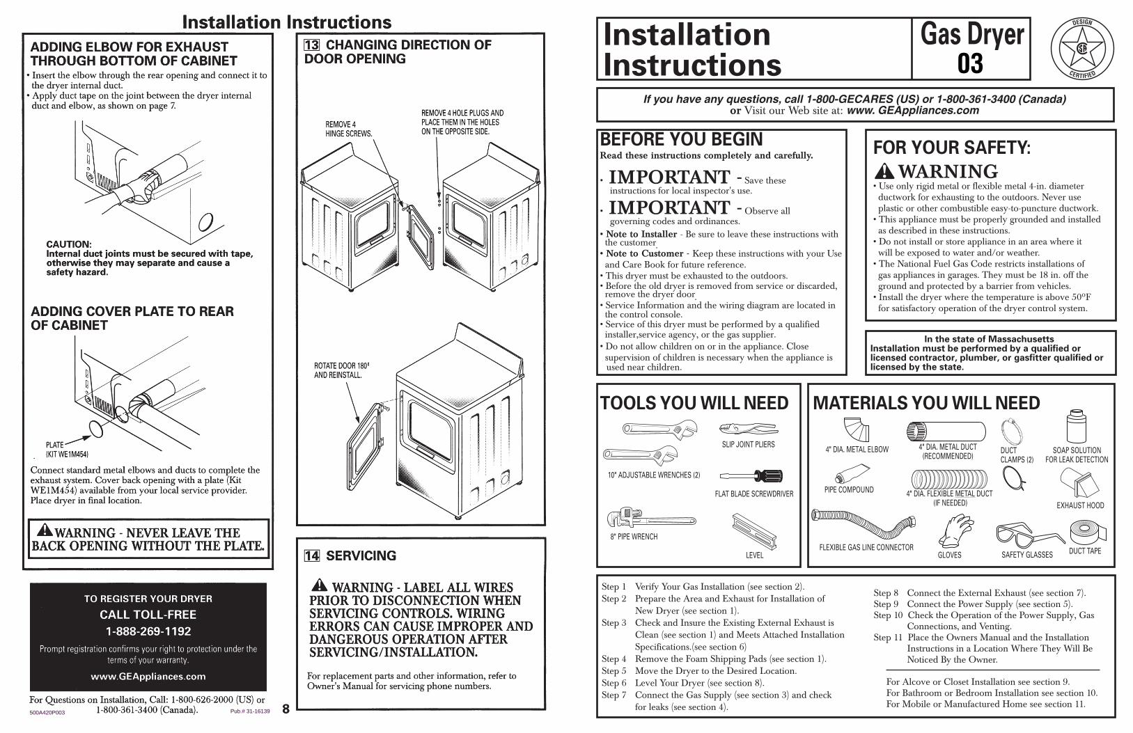
If rigid all-metal duct cannot be used, then flexible all-metal venting can be used, but it will reduce the maximum recommended duct length. In special installations when it is impossible to make connection with the above recommendations, then UL-listed clothes dryer transition duct may be used as transition venting between the dryer and wall connection only. The use of this ducting will affect dry time.
If flexible transition duct is necessary, the following directions must be followed.
• Use the Shortest Length Possible.• Stretch the Duct to Its Maximum Length.• Do Not Crush or Collapse.• Never Use Transition Duct Inside the Wall or Inside the Dryer.• Avoid Resting the Duct on Sharp Objects.• Venting Must Conform to Local Building Codes.
USING FLEXIBLE METAL DUCTS
ELBOWS HIGHLYRECOMMENDED
ELBOW HIGHLYRECOMMENDED
DO NOTSIT DRYERON FLEXIBLEEXHAUST.
DO NOT USEEXCESSIVEEXHAUSTLENGTH
DO NOTCRUSHFLEXIBLEEXHAUSTAGAINSTWALL.
• If your dryer is approved for installation in an alcove or closet, it will be stated on a label on the dryer back.• The dryer MUST be vented to the outdoors. See the EXHAUST INFORMATION section. • Minimum clearance between dryer cabinet and adjacent walls or other surfaces is:
0 in. either side3 in. front and rear
• Minimum vertical space from floor to overhead cabinets, ceiling, etc. is 52 in.• Closet doors must be louvered or otherwise ventilated and must contain a minimum of 60 sq. in. of open area equally distributed. If the closet contains both a washer and a dryer, doors must contain a minimum of 120 sq. in. of open area equally distributed.• The closet should be vented to the outdoors to prevent gas pocketing in case of a gas leak in the supply line.• No other fuel-burning appliance shall be installed in the same closet with the dryer.
• The dryer MUST be vented to the outdoors. See EXHAUST INFORMATION section 6.• The installation must conform with local codes or, in the absence of local codes, with the NATIONAL FUEL GAS CODE, ANSI Z223.
• Installation must conform to the MANUFACTURED HOME CONSTRUCTION & SAFETY STANDARD, TITLE 24, PART 32-80 or, when such standard is not applicable, with AMERICAN NATIONAL STANDARD FOR MOBILE HOME, NO. 501B.• The dryer MUST be vented to the outdoors with the termination securely fastened to the mobile home structure. (See EXHAUST INFORMATION section 6.)• The vent MUST NOT be terminated beneath a mobile or manufactured home.• The vent duct material MUST BE METAL.• KIT 14-D346-33 MUST be used to attach the dryer securely to the structure.• The vent MUST NOT be connected to any other duct, vent, or chimney.• Do not use sheet metal screws or other refastening devices which extend into the interior of the exhaust vent.• Provide an opening with a free area of at least 25 sq. in. for introduction of outside air into the dryer room.
DO
DON’T
3
4 LEAK TEST
Installation Instructions
3 RECONNECTING GAS
FLARE NPT
PIPE SIZE
Listed connector ANSI Z21.24 / CSA 6.10
Caution: Use adapters as shown. Connector nuts must not be connected directly to pipe threads.
Note: The connector and fittings are designed for use onlyon the original installation and are not to be reused foranother appliance or at another location. Keep flare end ofadaptor free of grease, oil and thread sealant.
1/8" NPT PIPEPLUG FORCHECKING GASINLET PRESSURE
PIPE SIZEAT LEAST 1/2"
3/8" NPT
TIGHTEN ALL CONNECTIONSUSING TWO ADJUSTABLE WRENCHES.DO NOT OVERTORQUE GAS CONNECTIONS!
TIGHTEN THE FLEXIBLEGAS LINE USING TWOADJUSTABLE WRENCHES.
5
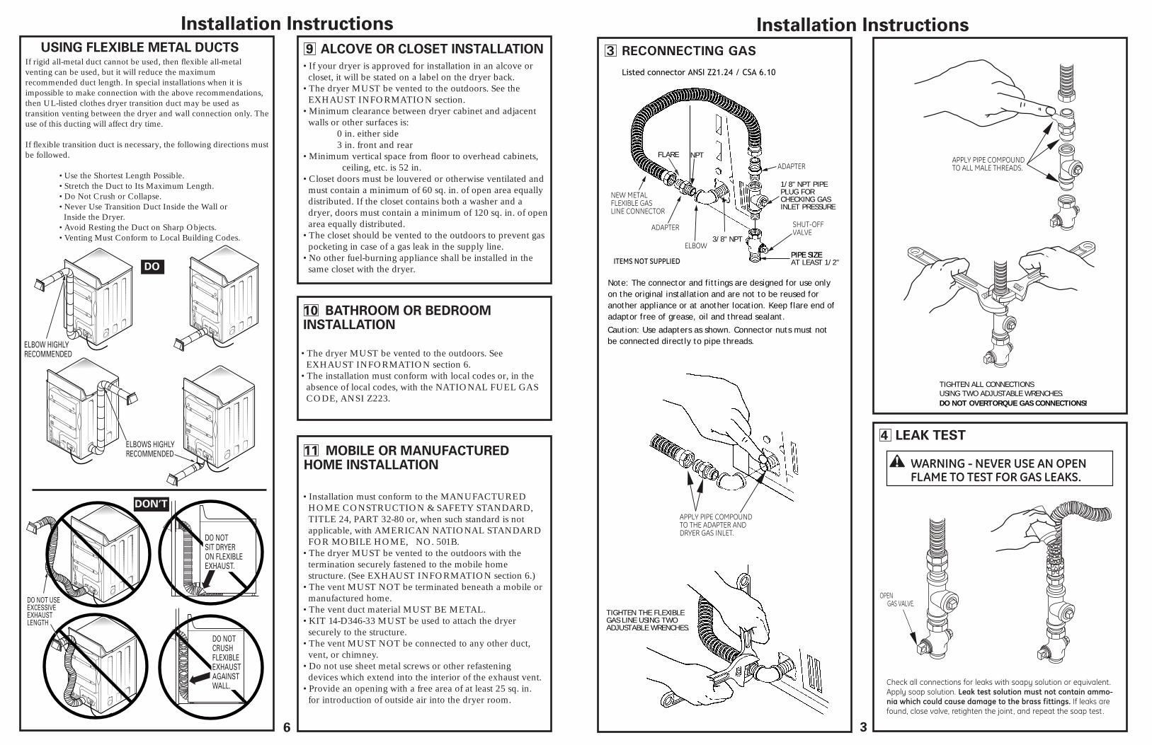
7 EXHAUST CONNECTION
8 LEVELING DRYER
Installation Instructions
WARNING - TO REDUCE THE RISKOF FIRE OR PERSONAL INJURY:
STANDARD REAR EXHAUST
• This dryer must be exhausted to the outdoors. • Use only metal duct.• Do not terminate exhaust in a chimney, any gas vent, under an enclosed floor (crawl space), or into an attic. The accumulated lint could create a fire hazard.• Provide an access for inspection and cleaning of the exhaust system, especially at turns. Inspect and clean at least once a year.• Never terminate the exhaust into a common duct with a kitchen exhaust. A combination of lint and grease could create a fire hazard.• Do not obstruct incoming or exhausted air.
THIS DRYER COMES READY FOR REAR EXHAUSTING. IFSPACE IS LIMITED, USE THE INSTRUCTIONS IN SECTION 12 TO EXHAUST DIRECTLY FROM THE LEFT SIDE ORBOTTOM OF THE CABINET.
WE RECOMMEND THAT YOU INSTALL YOUR DRYERBEFORE YOUR WASHER. THIS WILL PERMIT DIRECTACCESS FOR EASIER EXHAUST CONNECTION
WE STRONGLY RECOMMEND THE USE OFRIGID METAL EXHAUST DUCT. IF USINGFLEXABLE METAL DUCT, CUT IT TO THE PROPERLENGTH AND AVOID BUNCHING OF THE DUCTBEHIND THE DRYER.
FOR STRAIGHTLINE INSTALLATION,CONNECT THEDRYER EXHAUSTTO THE WALL USINGDUCT TAPE.
RECOMMENDEDCONFIGURATIONTO MINIMIZEEXHAUSTBLOCKAGE.
ELBOW HIGHLYRECOMMENDED.
ELBOW HIGHLYRECOMMENDED.
NOTE: ELBOWS WILL PREVENT DUCT
KINKING AND COLLAPSING.
LEVELSIDE-TO-SIDE.
4 LEVELING LEGS
2 ANTI-TIP LEGS
LEVELFRONT-TO-BACK.
STAND THE DRYER UPRIGHT NEAR THEFINAL LOCATION AND ADJUST THE 4 LEVELINGLEGS TO MATCH THE HEIGHT OF YOUR WASHER.ADJUST THE 2 ANTI-TIP LEGS TO CONTACTTHE FLOOR.