Installation and Operation Instructions - Aspen Systems€¦ · at least 2 cm away from the face of...
16
24 St. Martin Dr. Marlborough, MA 01752 Installation and Operation Instructions Liquid Chiller Module FP00039 Installations Notes Date of Purchase Date of Installation Installer Model Number Serial Number
Transcript of Installation and Operation Instructions - Aspen Systems€¦ · at least 2 cm away from the face of...

24 St. Martin Dr.
Marlborough, MA 01752
Installation and Operation Instructions
Liquid Chiller Module
FP00039
Installations Notes
Date of Purchase
Date of Installation
Installer
Model Number
Serial Number
OM00010 Rev A, FP00039 Operation Manual Page 2 of 7
Contents System Information ...................................................................................................................................... 2
Safety ............................................................................................................................................................ 3
General Operation ........................................................................................................................................ 3
Environmental ........................................................................................................................................... 3
Condenser Fan .......................................................................................................................................... 3
Fluid Connections ...................................................................................................................................... 3
Mounting................................................................................................................................................... 4
Power Supply ............................................................................................................................................ 4
Compressor Control .................................................................................................................................. 4
Performance ................................................................................................................................................. 5
Maintenance ................................................................................................................................................. 5
Customer Service .......................................................................................................................................... 6
Commercial Product Warranty ................................................................................................................. 6
Warranty Repairs ...................................................................................................................................... 6
Technical Support ..................................................................................................................................... 6
Aspen Contact Information ....................................................................................................................... 7
APPENDIX ...................................................................................................................................................... 7
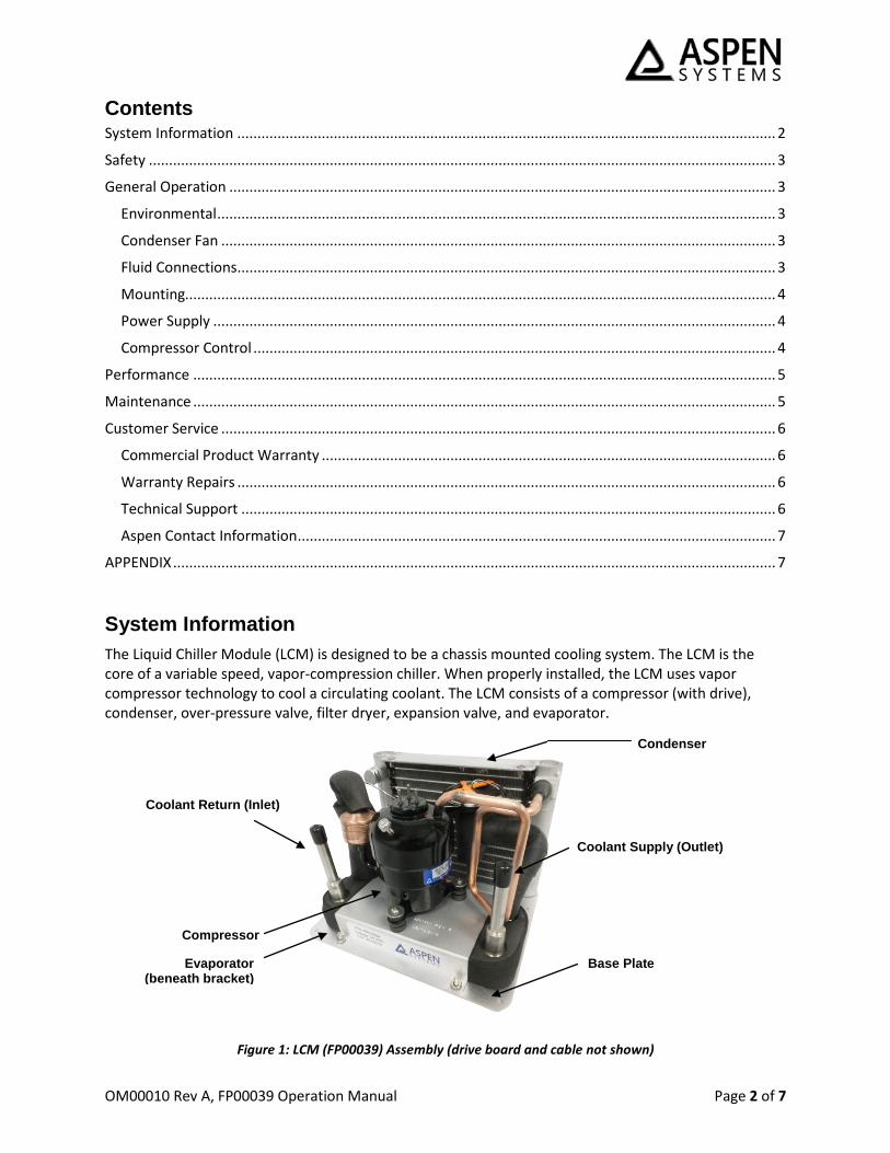
System Information The Liquid Chiller Module (LCM) is designed to be a chassis mounted cooling system. The LCM is the core of a variable speed, vapor-compression chiller. When properly installed, the LCM uses vapor compressor technology to cool a circulating coolant. The LCM consists of a compressor (with drive), condenser, over-pressure valve, filter dryer, expansion valve, and evaporator.
Figure 1: LCM (FP00039) Assembly (drive board and cable not shown)
Compressor
Condenser
Evaporator (beneath bracket)
Coolant Supply (Outlet)
Coolant Return (Inlet)
Base Plate
OM00010 Rev A, FP00039 Operation Manual Page 3 of 7
Safety The LCM contains Tetrafluoroethane (R-134a) as a refrigerant. R-134a is an approved long-term replacement for CFC-based refrigerants and an approved ozone depleting substance (ODS) alternative. In the event that the LCM is damaged, general work clothing, leather gloves, and eye protection should be worn to prevent exposure to refrigerants.
Precautions relating to the personnel hazards regarding contact with this substance should be outlined in training and technical manuals.
Disposal of R-134a must comply with federal, state, and local disposal or discharge laws.
General Operation Environmental
Coolant Water, Glycol/Water Mixtures (contact Aspen for use of other coolants)
Ambient (Operation) 0°C to 50°C (32°F – 122°F)
Ambient (Storage) -20°C to 50°C (-4°F – 122°F)
Weight 2.7 kg (6.0 lb)
Size 19.9 x 16.1 x 13.4 cm (7.8 x 6.3 x 5.3 in)
Condenser Fan
To operate properly, airflow must be provided to the condenser. A fan should be mounted on a plenum at least 2 cm away from the face of the condenser. Aspen recommends a 120 mm fan with at least 100 cfm of airflow. Smaller fans may require a larger plenum length to ensure proper airflow distribution.
Note: Aspen’s performance testing was conducted using: NMB-MAT: 4715KL-05W-B50
Fluid Connections
The LCM terminates with 3/8 inch stainless steel tubing. The user must adapt their cooling loop to these fittings. For low-to-moderate pressure applications (< 690 KPa [100 psi]), John Guest push-fit connectors may be used to interface with the LCM. The LCM can operate with a coolant pressure no greater than 2.07 MPa (300 psi).
Recommended Fitting: John Guest Superseal Speedfit: SI031212S
A coolant pump must be used to generate coolant flow across the evaporator. In order to achieve the maximum performance from the system, proper insulation of the coolant line is required.
CAUTION! When using a water-based coolant, care must be taken to avoid freezing the evaporator. The LCM is capable of freezing water within the evaporator in less than 1
minute if water flow stops or slows while the LCM continues to run. Freezing the evaporator could rupture the evaporator causing a water and/or refrigerant leak.
CAUTION! Skin contact with refrigerant may cause frostbite.
WARNING! R-134A is subject to U.S. Environmental Protection Agency Clean Air Act Regulations Section 608 in 40 CFR Part 82 regarding refrigerant recycling, therefore the
refrigerant must be evacuated from the ECU prior to disposal of the assembly.
OM00010 Rev A, FP00039 Operation Manual Page 4 of 7
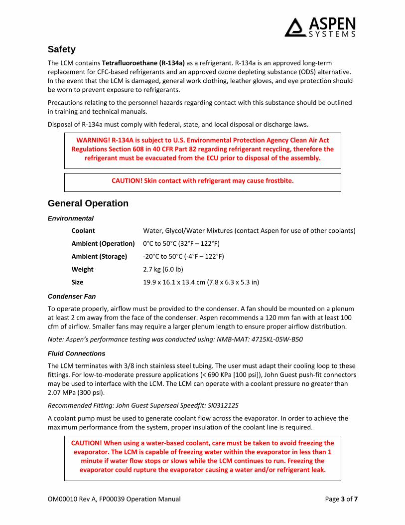
Mounting
The LCM is supplied on a base plate. There are four #6 clearance holes (0.15 inch diameter)) that can be used to hold down the LCM. There are two #6-32 nuts mounting the condenser and four #6-32 nuts mounting the evaporator bracket to the base plate. If the base plate is not required these nuts can be removed and the LCM can be mounted directly to the customer’s chassis. All six #6 clearance holes must be used in this mounting configuration. See drawing (Figure 2) for hole locations.
Figure 2: LCM Dimensional Drawing - Note all dimensions are in inches
Power Supply
The motor drive board shipped with the LCM is a 24 VDC unit. The operating voltage range is 22 VDC – 32 VDC. The LCM may draw up to 15 A of current during normal operation.
Compressor Control
Please refer to the Aspen Compressor High Capacity Drive manual (see appendix) for detailed wiring and functionality of the drive board.
The motor drive board is a variable speed drive. This allows the cooling capacity of the system to be adjusted by increasing or decreasing the compressor speed. The compressor drive board utilizes a user
CAUTION! Operating the LCM outside the voltage range will void the system warranty.
CAUTION! The LCM must be operated in the vertical orientation. Operation of the system at an orientation of >30° from vertical may result in reduced system capacity or
damage to the compressor.
OM00010 Rev A, FP00039 Operation Manual Page 5 of 7
supplied 0-5 VDC analog signal to set the compressor speed. The firmware has a minimum speed of 2200 RPM (0.7 VDC or lower) and a maximum speed of 6500 RPM (4.5 VDC or higher). The voltage to RPM relationship is linear between 0.7 and 4.5 V so the following equation can be used:
S = 1132 × V + 1408
Where S is compressor speed (RPM) and V is the control voltage (VDC).
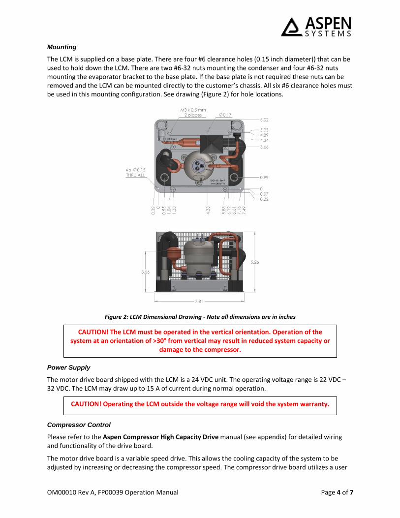
Performance The performance curve below (Figure 2) defines the performance of the LCM. The data shown below derived using 2 L/min water flow with 150 cfm airflow.
Figure 3: LCM Performance Map for Water
Maintenance The LCM is a sealed unit and does not require regular maintenance to operate. Depending on environmental conditions the condenser fins could become fouled with dust and debris. A fouled condenser will cause the LCM to operate inefficiently and potential shut down. To clean the condenser follow the steps below. All work should be performed while wearing safety glasses and ear protection with the LCM powered off.
1. Remove the plenum and any duct work covering the condenser. 2. Attach an air nozzle to a compressed air source regulated to between 50 and 100 psi. 3. Direct the air at the face of the condenser in the opposite direction the fan blows. Keep the
nozzle 2 to 4 inches from the face of the condenser. The air flow should be very close to perpendicular to the face of the coils.
4. Sweep the air flow back and forth across the face of the coil to remove and excess
contamination which would have built up during use until clean. 5. Reattach the plenum and any ducting.
CAUTION! Directing airflow at the condenser fins at an angle may result in bending/damage of the LCM fins, resulting in decreased condenser performance.

OM00010 Rev A, FP00039 Operation Manual Page 6 of 7
Customer Service Commercial Product Warranty
Aspen System Inc. (hereinafter referred to as “Aspen”), warrants to the original purchaser that products sold shall be free from defects in material and workmanship for the warranty period not to exceed one year from the date of shipment. If buyer claims that a product violates such warranty, Aspen, upon notice promptly given, will either examine the product at buyer’s site, or issue shipping instructions for return to Aspen at buyer’s expense, transportation charges prepaid.
Aspen’s sole obligation under its warranty shall be, at its option, to repair, replace or refund the price of any product thereof which is proved to violate such warranty. In no event, whether based on contract, indemnity, warranty, tort (including negligence), strict liability or otherwise, shall Aspen be liable to the buyer for special, indirect, incidental or consequential damages whatsoever including, without limitation, loss of profit or revenue.
The above warranty is buyer’s exclusive remedy and Aspen hereby expressly disclaims all other warranties, express or implied, including the implied warranty of merchantability and the implied warranty of fitness for a particular purpose. The foregoing shall constitute the sole remedy of the buyer and the sole liability of Aspen.
This Limited Warranty shall not apply to any product or component thereof which has been repaired or altered outside of Aspen’s factory in any manner so as, in Aspen’s sole judgment, to affect its serviceability, or to any product that has been subject to alteration, accident, misuse, abuse, neglect or normal wear. The Limited Warranty shall not apply to products which have been assembled or installed or used in a manner contrary to Aspen’s printed instructions, or due to failure to follow Aspen printed instructions for operation and maintenance. This product is designed and intended to be installed and operated in an enclosure that is sealed from the ambient environment. Exposure to water leakage into the enclosure and/or excessive condensation from exposure to humid ambient air during operation will void this warranty. Any technical assistance provided by Aspen’s personnel or representatives in system design is construed to be a proposal and not a recommendation. The responsibility for determining feasibility rests with the user and should be subject to test. Only the terms expressed in this Limited Warranty shall apply and no distributor, corporation or individual is authorized to amend, modify or extend this warranty in any way on resale.
Warranty Repairs
Any product returned and found to be under warranty will be repaired or replaced at the discretion of Aspen Systems, Inc. Depending on the circumstances of the problem, it may be deemed necessary to return the products to Aspen Systems, Inc. for repair. In order to return the product for repair, please contact Aspen Systems via email, telephone, or through the Aspen Systems’ website (see Contact Information)
Technical Support
Technical Support is available from Aspen Systems from 8:00 AM to 5:00 PM (EST) Monday through Friday via phone or email (see contact information). Technical support can also be requested on-line. To expedite assistance for problems, be able to provide the following information:
• Your name, phone number, company, division and city. • Product number, serial number and revision (located on the LCM evaporator bracket). • A detailed description of your problem.
OM00010 Rev A, FP00039 Operation Manual Page 7 of 7
Aspen Contact Information
Email: [email protected] Phone: 508-281-5322 Website: http://aspensystems.com/contact
APPENDIX
Sept, 2014 Rev. 11 1 of 9
ASPEN COMPRESSOR Appendix High Capacity Drive
Wiring & Operating Instructions
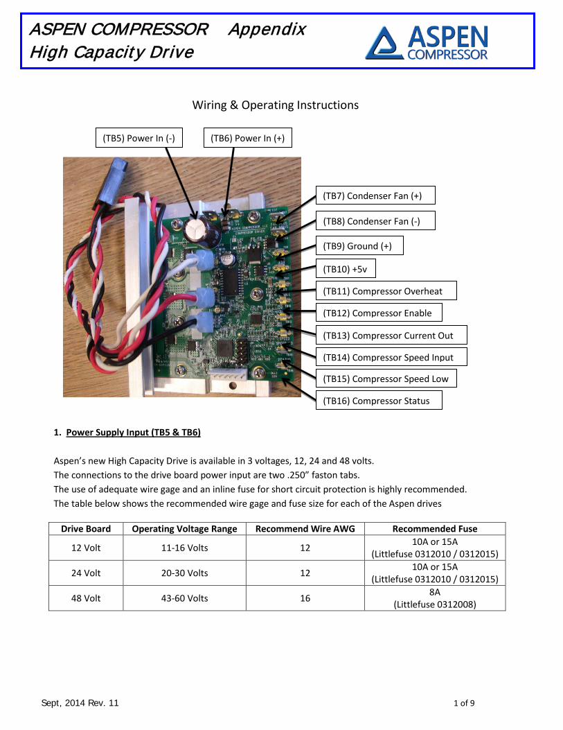
1. Power Supply Input (TB5 & TB6)
Aspen’s new High Capacity Drive is available in 3 voltages, 12, 24 and 48 volts. The connections to the drive board power input are two .250” faston tabs. The use of adequate wire gage and an inline fuse for short circuit protection is highly recommended. The table below shows the recommended wire gage and fuse size for each of the Aspen drives
Drive Board Operating Voltage Range Recommend Wire AWG Recommended Fuse
12 Volt 11-16 Volts 12 10A or 15A
(Littlefuse 0312010 / 0312015)
24 Volt 20-30 Volts 12 10A or 15A
(Littlefuse 0312010 / 0312015)
48 Volt 43-60 Volts 16 8A
(Littlefuse 0312008)
(TB7) Condenser Fan (+)
(TB5) Power In (-) (TB6) Power In (+)
(TB8) Condenser Fan (-)
(TB11) Compressor Overheat
(TB9) Ground (+)
(TB10) +5v
(TB12) Compressor Enable
(TB13) Compressor Current Out
(TB14) Compressor Speed Input
(TB15) Compressor Speed Low
(TB16) Compressor Status

Sept, 2014 Rev. 11 2 of 9
ASPEN COMPRESSOR Appendix High Capacity Drive
2. Condenser Fan Output (TB7 & TB8) An output has been provided for running condenser fan(s) from the Aspen drive. The voltage of this output will be equivalent to the DC input voltage provided to the board. The power to the condenser fan is enabled 10 seconds after the drive starts the compressor. Therefore, when the compressor is off, the power to the condenser fan(s) is off. When the compressor is signaled to run, the power to the condenser fan(s) will be enabled 10 seconds after the compressor has started running. This 10 second delay is intentional and is meant to reduce the total amount of inrush current when the compressor starts. The connections to the condenser fan outputs are two .250” faston tabs. The condenser fan output should be limited to a maximum of 5 amps on 12/24 volts boards and 3 amps on 48 volt boards.
3. Ground (TB9) The ground tab is for connecting both the compressor enable and compressor over temp connections to. Both the compressor enable and the compressor overheat connections must be connected to ground in order for the compressor to operate. The connection to the ground is a .187” faston tab.
4. +5V (TB10) The +5v tab is provided to give the user the ability to provide a low voltage speed signal input without the use of an additional power supply. The 5 volts can be wired directly to the speed input tab, which will cause the compressor to operate at full speed, or can be wired to a 20k potentiometer to allow the user to vary the voltage to the speed input tab and vary the speed of the compressor. The connection to the +5v is a .187” faston tab.
5. Compressor Overheat (TB11) In order for the compressor to operate, the overheat tab connection must either be connected directly to ground, or connected to an optional thermal safety switch, which is then connected to ground. When used in conjunction with the thermal switch, the drive will shut the compressor off when the thermal switch indicates that the compressor has overheated. Once this has occurred, the board will flash the red LED a sequence of 16 flashes to indicate that the compressor has overheated. To restart the compressor, the thermal switch must reset and the user must be either cycle the main power on the drive board or momentarily disconnect the enable wire from ground. The connection to the compressor overheat is a .187” faston tab.
6. Compressor Enable (TB12) In order for the compressor to operate, the compressor enable tab connection must be connected to ground. This connection can also be wired through a thermostat and then to ground to cycle the compressor on and off via a thermostat. The connection to the compressor enable is a .187” faston tab.
7. Compressor Current Out (TB13) The drive is equipped with a current out connection to allow the user to monitor the current consumption of the compressor. The current out connection puts out a voltage that correlates to the current being used by the compressor only and not the condenser fans if they are so attached. The correlation is .1 volts per amp, so if the compressor is using 5 amps of power, the voltage measure on the current out tab will be .5 volts. The connection to the compressor current out is a .187” faston tab.
Sept, 2014 Rev. 11 3 of 9
ASPEN COMPRESSOR Appendix High Capacity Drive
8. Compressor Speed Input (TB14) A voltage must be applied to the compressor speed input tab in order for the compressor to operate. The compressor speed input accepts a 0-5 vdc analog voltage signal and will regulate the speed of the compressor automatically with respect to this input voltage. The compressor will turn on once the input voltage has reached ~.8 volts and off once the input voltage has dropped below .6 volts. There will be a linear increase in speed from the turn on voltage of .8 volts (~2200 rpm) through the max speed voltage of 4.5 volts (~6500 rpm). There is no addition increase in speed between 4.5-5 volts. The connection to the compressor speed input is a .187” faston tab.
9. Compressor Speed Low (TB15) This tab should be used when a secondary power supply is being used to supply power for speed control and the user wants the secondary supply to be isolated from the power supply being used to power the drive. In this case the factory installed jumper should be removed. This will decouple the board ground reference and allow the secondary power supply source for speed control to be completely isolated. The secondary power supply for speed control can then be wired between the speed input and speed low connections to vary compressor speed. The connection to the compressor speed low is a .187” faston tab. See the jumper configuration table at the end of this section for details.
10. Compressor Status (TB16) This tab is available to the end user so that they can monitor the normal operation of the compressor. When speed signal is being sent to the drive and the compressor is operating normally, there will be no voltage on this connection. However, if a speed signal is present and the compressor enable is satisfied but the compressor is not running, 5 volts will be present on this tab. This 5v signal can be monitored to alert the end user that there is a problem with the system and that the compressor is not running.

Sept, 2014 Rev. 11 4 of 9
ASPEN COMPRESSOR Appendix High Capacity Drive
Additional Board Functions
1. Compressor Start Delay – The Aspen high capacity drive has the ability to delay the compressor start in situations where starting may be difficult due to an unbalanced system. The logic behind the delay is based on a minimum off time for the compressor and can be enabled by installing jumpers per the table at the end of this section. When activated the controller keeps track of how long the compressor has been turned off before trying to restart. If the compressor has been off for the minimum amount of time set by the jumpers when there is a call to restart, it will start immediately. If the minimum amount of time has not passed, the compressor will wait until the minimum time has been reached before attempting to start.
2. Board Overheat – The Aspen high capacity drive has an onboard thermistor that enables the drive to
prevent itself from overheating. When the board detects that it has overheated, the drive will stop the compressor and emit a series of 8 flashes on the red LED.
3. Automatic Current Limiting – The Aspen high capacity drive has the ability to regulate the amount of
current being used by the compressor. While the 48V drive has an 8 amp limit, the 12/24 drive has two limits for the current control. One is 15 amps and the other one is 10 amps and can be set by the jumpers in the table at the end of this section. The drive will automatically monitor the current consumption of the compressor. If the compressor begins to draw more than the maximum set current, the drive will automatically decrease the speed of the compressor in an effort to reduce the current being used. Once the speed of the compressor has been reduced below the minimum compressor speed, the drive will stop the compressor and flash the red LED continuously to allow the user to know that the compressor has stalled from excessive current draw or a lock rotor condition. It should be noted that the automatic current limit only reduces the current used by the compressor and does not account for any current that may be drawn by the use of the condenser fan output.
4. Lock Rotor Protection - The Aspen high capacity drive has the ability to detect if the compressor is not
running due to a lock rotor condition. After the drive has made several unsuccessful attempts to start the compressor, the drive will stop attempting to start the compressor and flash the red LED continuously to allow the user to know that the compressor has stalled from excessive current draw or a lock rotor condition.
5. Error Clearing – The drive can go in to error mode for several reasons in which case the compressor will
stop running. To clear the error and restart the compressor, the enable wire must be disconnected and then reconnected to ground. For a list of error conditions, see the error code table at the end of this section.

Sept, 2014 Rev. 11 5 of 9
ASPEN COMPRESSOR Appendix High Capacity Drive
Compressor Wiring – The Aspen high capacity drive is supplied with a cable to attach the drive to the compressor. All other wiring is to be supplied by the end user. It is important to wire the compressor to the drive with the colors coded in the order per the picture below. If the order of the wires is not correct, the compressor will not operate properly.
(TB3) White Wire
(TB2) Red Wire
(TB1) Black Wire

Sept, 2014 Rev. 11 6 of 9
ASPEN COMPRESSOR Appendix High Capacity Drive
Jumper Configuration – There 5 jumpers (4 user selectable) that can be adjusted to change the configuration of the drive. The tables below provide detailed information on how to configure the jumpers.
Start Delay Jumpers To Install Off None
30 sec Location 2 60 sec Location 3
120 sec Location 2 & 3
Jumper Position
Function Installed Not Installed
5 Speed Low Isolation
Not Isolated (Factory Default)
Isolated
4 Current Limit 10 Amps 15 Amps (Factory Default) See Application
Note Below 3 Start Delay See table See table 2 Start Delay See table See table 1 Voltage Setting Consult Factory Consult Factory
** Application Note ** When operating a new Q-Series type compressor, either the 10 amp or 15 amp setting may be used. When operating a standard compressor, only the 10 amp setting should be used or the compressor may not operate properly at high current levels.
Q Series Compressor Jumper 4 can be configured to 10 amps or 15 amps current limiting Factory default setting is 15 amps.
Standard Compressor Jumper #4 factory default setting is 15 amps and must be changed to 10 amps for operating this style compressor. Install jumper in position 4 whenever operating this type of compressor.
Sept, 2014 Rev. 11 7 of 9
ASPEN COMPRESSOR Appendix High Capacity Drive
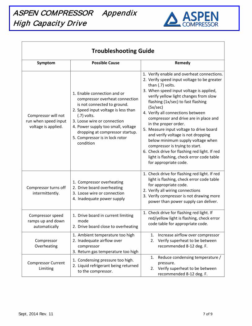
Troubleshooting Guide
Symptom Possible Cause
Remedy
Compressor will not run when speed input
voltage is applied.
1. Enable connection and or compressor overheat connection is not connected to ground.
2. Speed input voltage is less than (.7) volts.
3. Loose wire or connection 4. Power supply too small, voltage
dropping at compressor startup. 5. Compressor is in lock rotor
condition
1. Verify enable and overheat connections. 2. Verify speed input voltage to be greater
than (.7) volts. 3. When speed input voltage is applied,
verify yellow light changes from slow flashing (1x/sec) to fast flashing (5x/sec)
4. Verify all connections between compressor and drive are in place and in the proper order.
5. Measure input voltage to drive board and verify voltage is not dropping below minimum supply voltage when compressor is trying to start.
6. Check drive for flashing red light. If red light is flashing, check error code table for appropriate code.
Compressor turns off intermittently.
1. Compressor overheating 2. Drive board overheating 3. Loose wire or connection 4. Inadequate power supply
1. Check drive for flashing red light. If red light is flashing, check error code table for appropriate code.
2. Verify all wiring connections 3. Verify compressor is not drawing more
power than power supply can deliver.
Compressor speed ramps up and down
automatically
1. Drive board in current limiting mode
2. Drive board close to overheating
1. Check drive for flashing red light. If red/yellow light is flashing, check error code table for appropriate code.
Compressor Overheating
1. Ambient temperature too high 2. Inadequate airflow over
compressor 3. Return gas temperature too high
1. Increase airflow over compressor 2. Verify superheat to be between
recommended 8-12 deg. F.
Compressor Current Limiting
1. Condensing pressure too high. 2. Liquid refrigerant being returned
to the compressor.
1. Reduce condensing temperature / pressure.
2. Verify superheat to be between recommended 8-12 deg. F.

Sept, 2014 Rev. 11 8 of 9
ASPEN COMPRESSOR Appendix High Capacity Drive
Drive LED / Error Code Table Red LED Yellow LED Normal Operation (Compressor not running) Slow Flash ~ 1x/sec Normal Operation (Compressor Running) Fast Flash ~ 5x/sec Compressor stall / lock rotor 1 Flash Repeating Supply voltage too low 4 Flashes Repeating Board overheated 8 Flashes Repeating Compressor overheated 16 Flashes Repeating
Mounting Diagram
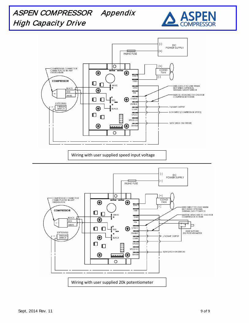
Typical Wiring Diagram
Sept, 2014 Rev. 11 9 of 9
ASPEN COMPRESSOR Appendix High Capacity Drive
_______________________________________________________________
Wiring with user supplied speed input voltage
Wiring with user supplied 20k potentiometer