INSTALLATION AND OPERATING INSTRUCTIONS GN2 Inst.pdf · INSTALLATION AND OPERATING INSTRUCTIONS GN2...
24
INSTALLATION AND OPERATING INSTRUCTIONS GN2 HIGH EFFICIENCY CAST IRON BOILER FOR LIQUID and/or GAS FUELS
Transcript of INSTALLATION AND OPERATING INSTRUCTIONS GN2 Inst.pdf · INSTALLATION AND OPERATING INSTRUCTIONS GN2...

INSTALLATION AND OPERATINGINSTRUCTIONS
GN2HIGH EFFICIENCY
CAST IRON BOILERFOR LIQUID and/or
GAS FUELS

2GN2
INDEX1. Technical information .............................................................................................................................. page 32. Dimensional and technical characteristics .............................................................................................. page 33. Packing and dispatch ........................... .................................................................................................. page 54. Boiler assembly ....................................................................................................................................... page 65. Shell assembly .............................................................................................................................. ......... page 116. Installation ............................................................................................................................................... page 197. Inspections and adjustments................................................................................................................... page 208. Maintenance............................................................................................................................................ page 219. Boiler parts .............................................................................................................................................. page 22
3GN2
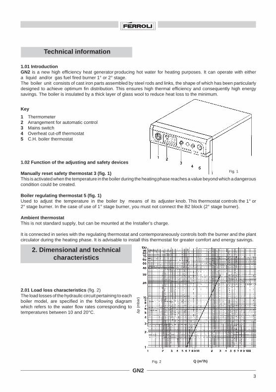
Q (m3/h)Fig. 2
Technical information
1.01 IntroductionGN2 is a new high efficiency heat generator producing hot water for heating purposes. It can operate with eithera liquid and/or gas fuel fired burner 1° or 2° stage.The boiler unit consists of cast iron parts assembled by steel rods and links, the shape of which has been particularlydesigned to achieve optimum fin distribution. This ensures high thermal efficiency and consequently high energysavings. The boiler is insulated by a thick layer of glass wool to reduce heat loss to the minimum.
Fig. 1
2. Dimensional and technicalcharacteristics
2.01 Load loss characteristics (fig. 2)The load losses of the hydraulic circuit pertaining to eachboiler model, are specified in the following diagramwhich refers to the water flow rates corresponding totemperatures between 10 and 20°C.
1.02 Function of the adjusting and safety devices
Manually reset safety thermostat 3 (fig. 1)This is activated when the temperature in the boiler during the heating phase reaches a value beyond which a dangerouscondition could be created.
Boiler regulating thermostat 5 (fig. 1)Used to adjust the temperature in the boiler by means of its adjuster knob. This thermostat controls the 1° or2° stage burner. In the case of use of 1° stage burner, you must not connect the B2 block (2° stage burner).
Ambient thermostatThis is not standard supply, but can be mounted at the Installer’s charge.
It is connected in series with the regulating thermostat and contemporaneously controls both the burner and the plantcirculator during the heating phase. It is advisable to install this thermostat for greater comfort and energy savings.
Key
1 Thermometer2 Arrangement for automatic control3 Mains switch4 Overheat cut-off thermostat5 C.H. boiler thermostat
∆p (
mba
r)
4GN2
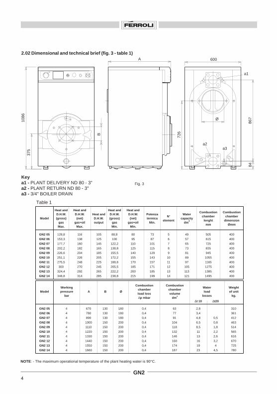
2.02 Dimensional and technical brief (fig. 3 - table 1)
NOTE: - The maximum operational temperature of the plant heating water is 90°C.
Table 1
Fig. 3
Keya1 - PLANT DELIVERY ND 80 - 3"a2 - PLANT RETURN ND 80 - 3"a3 - 3/4" BOILER DRAIN
A 600
1086
867
84
726
Ø
375
B
a1
a2a3
30
0 90
60
120
60
0
°C
4
4
4
4
4
4
4
4
4
4
Workingpressure
bar
670
780
890
1000
1110
1220
1330
1440
1550
1660
A
130
130
130
150
150
150
150
150
150
150
B
180
180
180
200
200
200
200
200
200
200
Ø
0,4
0,4
0,4
0,4
0,4
0,4
0,4
0,4
0,4
0,4
Combustionchamberload loss∆p mbar
63
77
91
104
118
132
146
160
174
187
Combustionchambervolume
dm3
Waterload
losses
0,5
0,8
1,8
2,2
2,6
3,2
4
4,5
∆t20
2,8
3,4
4,8
6,5
8,5
11
13
16
19
23
∆t 10
310
361
412
463
514
565
616
670
725
780
Weightof unit
kg.Model
GN2 05
GN2 06
GN2 07
GN2 08
GN2 09
GN2 10
GN2 11
GN2 12
GN2 13
GN2 14
Model
GN2 05
GN2 06
GN2 07
GN2 08
GN2 09
GN2 10
GN2 11
GN2 12
GN2 13
GN2 14
128,8
153,3
177,7
202,2
226,6
251,1
275,5
300
324,4
348,8
Heat andD.H.W.(gross)
gasMax.
116
138
160
182
204
226
248
270
292
314
Heat andD.H.W.(net)
gas+oilMax.
88,8
100
122,2
138,8
155,5
172,2
188,8
205,5
222,2
238,8
Heat andD.H.W.(gross)
gasMin.
80
95
110
125
140
155
170
185
200
215
Heat andD.H.W.(net)
gas+oilMin.
73
87
101
115
129
143
157
171
185
199
Potenzatermica
Min.
105
125
145
165
185
205
225
245
265
285
Heat andD.H.W.output
5
6
7
8
9
10
11
12
13
14
N°element
49
57
65
73
81
89
97
105
113
121
Watercapacity
dm3
505
615
725
835
945
1055
1165
1275
1385
1495
Combustionchamber
lenghtmm
400
400
400
400
400
400
400
400
400
400
Combustionchamber
dimensionØmm

5GN2
Fig. 4
1. Boiler unit
5. Accessory kit
2. Shell
3. Control panel
4. Elements
Boiler GN2 can be supplied in two versions, with theboiler unit either assembled or in parts.
Three packs will be dispatched in the first case:1. Boiler unit2. Shell3. Control panel
In the second case, there will be the following 4 packs:2. Shell3. Control panel4. Kit of parts forming the boiler unit5. Kit of accessories with which to mount the elements.
3. Packing and dispatch (fig. 4)
6GN2
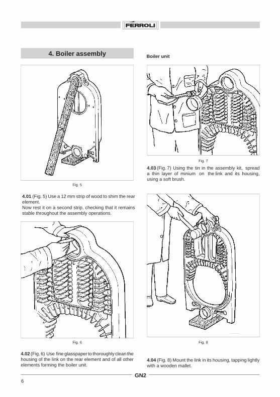
4.01 (Fig. 5) Use a 12 mm strip of wood to shim the rearelement.Now rest it on a second strip, checking that it remainsstable throughout the assembly operations.
4. Boiler assembly
Fig. 5
Fig. 6
Fig. 7
4.03 (Fig. 7) Using the tin in the assembly kit, spreada thin layer of minium on the link and its housing,using a soft brush.
Fig. 8
4.04 (Fig. 8) Mount the link in its housing, tapping lightlywith a wooden mallet.
4.02 (Fig. 6) Use fine glasspaper to thoroughly clean thehousing of the link on the rear element and of all otherelements forming the boiler unit.
Boiler unit
7GN2
Fig. 10
Fig. 11
Fig. 12
Fig. 9
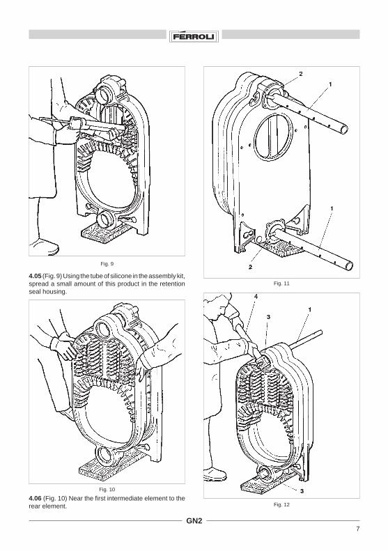
4.05 (Fig. 9) Using the tube of silicone in the assembly kit,spread a small amount of this product in the retentionseal housing.
4.06 (Fig. 10) Near the first intermediate element to therear element.

8GN2
ROD GN2 12 ELEM. LG. TOT. 1290
ROD GN2 12 ELEM. LG. TOT. 1290
ROD GN2 14 ELEM. LG. TOT. 1510
Fig. 16
Fig. 13
4.07 (Figs 11 - 12 - 13) Insert rod 1 between the twoelements, mount nut 3 on the threaded end, place stoppin 2 on the hole of the rod near the pair of elements thenclamp the unit together using a N° 4 wrench until thetwo elements have been perfectly joined together.
4.08 Proceed as described in the previous paragraphuntil all the elements forming the boiler unit have beenmounted.
Fig. 14
4.09 (Figs 14 - 15 - 16) Mount the four rods «1», theBelleville washers «2» as shown in fig. 15 and finallytorque nuts «3».
Fig. 15
Mounting the rods with the Belleville washers.NOTE: The Belleville washers must be mounted in anopposed way as shown in the diagram while the nutsmust be fixed in order to prevent them from beingcrushed.
For GN2 boilers with 12 - 13 - 14 elements, mount therods with sleeve part 1, remembering to fully tighten thesleeve thread on both sides.
9GN2
Fig. 17
Fig. 19
Fig. 20
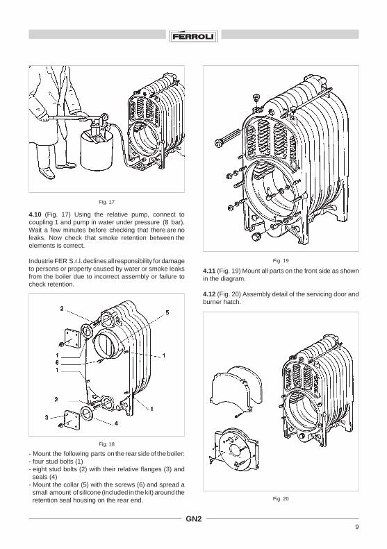
4.10 (Fig. 17) Using the relative pump, connect tocoupling 1 and pump in water under pressure (8 bar).Wait a few minutes before checking that there are noleaks. Now check that smoke retention between theelements is correct.
Industrie FER S.r.l. declines all responsibility for damageto persons or property caused by water or smoke leaksfrom the boiler due to incorrect assembly or failure tocheck retention.
Fig. 18
- Mount the following parts on the rear side of the boiler:- four stud bolts (1)- eight stud bolts (2) with their relative flanges (3) and
seals (4)- Mount the collar (5) with the screws (6) and spread a
small amount of silicone (included in the kit) around theretention seal housing on the rear end.
4.11 (Fig. 19) Mount all parts on the front side as shownin the diagram.
4.12 (Fig. 20) Assembly detail of the servicing door andburner hatch.

10GN2
1
4.13 (Fig. 21) Cover the boiler unit with the supplied mineral wool insulation.
4.14 (Fig. 22) The boiler unit can also be supplied already assembled. It will be sent straight from the factory on a pallet.Remove bolts 1 fixing the boiler to the pallet and place the boiler itself in its final installation position. Now proceed bymounting the various panels.
Fig. 21
Fig. 22

11GN2
2
1
4.15 (Fig. 23) When positioning the boiler unit, check that after burner assembly the front door is able to open withoutstriking against the wall or any other nearby boiler, i.e. leave a space of at least 100 mm as shown in the figure.
5. Shell assembly
Fig. 24
5.01 (Fig. 24) Mount rear panel 1 on stud bolts 2 without fixing it.
Fig. 23
12GN2
13÷14 el.
9÷12 el.5÷8 el.
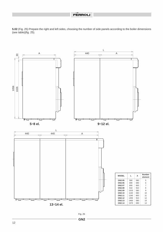
5.02 (Fig. 25) Prepare the right and left sides, choosing the number of side panels according to the boiler dimensions(see table)(fig. 25).
Fig. 25
A
1056
1026
30
A440L
A440L
440
GN2.05GN2.06GN2.07GN2.08GN2.09GN2.10GN2.11GN2.12GN2.13GN2.14
580690800910
102011301240135014601570
580690800910580690800910580690
56789
1011121314
MODEL L ANumberelement

13GN2
1
5.03 (Fig. 26) Connect the panels together using screws 1, washers 2 and nuts 3, reinforcing their lower part with strips4 fixed with screws 5.
Fig. 27
Fig. 26
5.04 (Fig. 27) Slacken nuts 1 on the right-hand side of the boiler.

14GN2
2
1
1
5.05 (Fig. 28) Insert the complete right side between rods1 and the boiler unit, checking that the machined slotsfit into their correct position. Now torque nuts 2.
5.06 (Fig. 29) Fix the right-hand side to the rear panelusing screws 1.
Fig. 28
Fig. 29

15GN2
2
1
5.09 (Fig. 31) Fix front lower panel 2 with the four self-threading screws 1.
Fig. 31
5.08 Now fix the left-hand side to the rear panel using screws 1 in the same way as right side assembly (fig. 29).
5.07 (Fig. 30) Slacken nuts 1 on the left-hand side ofthe boiler and mount the left-hand side part, checkingthat the machined slots fit into their correct position. Nowtorque nuts 1.
Fig. 30

16GN2
Fig. 32
5.10 Overturn the capillary tube of water gauge 6 (fig. 1) and screw its union to the relative sheath on the front partof the boiler unit (fig. 32).
Fig. 33
5.11 (Fig. 33) Fix the upper panel 1, according to thedimension of the boiler. Prepare the front lower pannel 2,fixing the grommet 3 for the cable of the burner. Fix angle4 on the both sides. Fix the safety wiring box 5 on upperangle.
17GN2
Fig. 35
Fig. 34
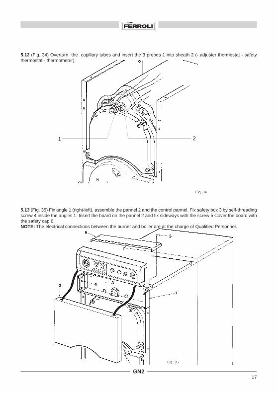
5.13 (Fig. 35) Fix angle 1 (right-left), assemble the pannel 2 and the control pannel. Fix safety box 3 by self-threadingscrew 4 inside the angles 1. Insert the board on the pannel 2 and fix sideways with the screw 5 Cover the board withthe safety cap 6.NOTE: The electrical connections between the burner and boiler are at the charge of Qualified Personnel.
5.12 (Fig. 34) Overturn the capillary tubes and insert the 3 probes 1 into sheath 2 (- adjuster thermostat - safetythermostat - thermometer).
1 2
18GN2
1
2
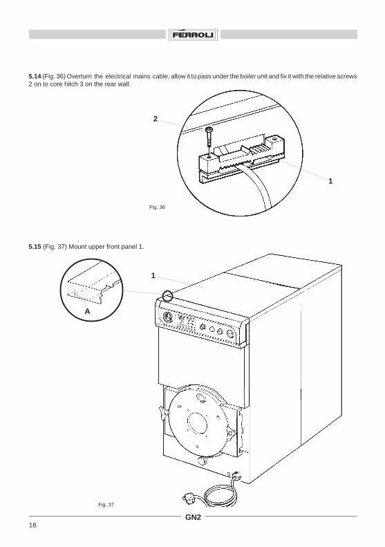
5.14 (Fig. 36) Overturn the electrical mains cable, allow it to pass under the boiler unit and fix it with the relative screws2 on to core hitch 3 on the rear wall.
Fig. 36
Fig. 37
5.15 (Fig. 37) Mount upper front panel 1.
1
A

19GN2
Key
Fig. 38
6. Installation
Boiler installation must only be carried out by Qualified Personnel in compliance with the Manufacturer’s instructionsand according to all laws and provisions in merit.You are particularly advised to comply with all safety regulations governing the construction and location of smokestacks.
6.01 Electrical connectionConnect the circulator, the burner and the ambient thermostat (if used) according to the indications applied to the relativecables and in compliance with the enclosed wiring diagram (fig. 38). Always install a bipolar circuit-breaker betweenthe mains socket and the appliance. The opening between the contacts of this circuit-breaker should be at least 3 mmand it should be equipped with fuses.
Always connect the appliance to a good grounding system. Industrie FERROLI S.p.A. declines all responsibilityfor damages to persons or property caused by failure to connect the appliance to a good grounding system.
230V 50Hz
L
B2B1
N
CA2ST
3 421
IL
5 6 7 8 9 10 11 12
N
B5
T8
T7
T6B4
T1 T2
S3
NL1
TS
11
TR2 1222
21
TR1
IL
230V50Hz
CA
1
L
TS
2
3
5
L1
T1
T2
N
T6
B5
B4
S3
B1
T8
T7B2
2ST
12
10 116
8
9
22
21
TR112
TR2
11
74
IL = Main switchCA = Contact auxiliary
TR1 = Boiler thermostat 1 stageTR2 = Boiler thermostat 2 stage
TS = Safety thermostatB1 = Burner 1 stageB2 = Burner 2 stage
2ST = Contact 2 stageRemove the line if roomthermostat is fitted

20GN2
6.02 Connection to the water mainConnect the appliance to the water main in compliance with the indications given near each coupling and accordingto those shown in figure 2 of this handbook.Connection must ensure that the pipes are free from tensions. It is essential to mount a safety valve on the heating circuitas near as possible to the boiler without any obstructions or on-off device between this and the valve itself.The appliance is not supplied with expansion tank. Connection to this device must therefore be carried out by theInstaller.
6.03 Connection to the smoke stackAlways connect the boiler to a good smoke stack built in compliance with the current provisions in merit. The ductbetween the boiler and the smoke stack must be made of a suitable material, i.e. able to withstand the temperaturesand rust resistant. Always check that all joints are well sealed and thermally insulate the entire duct between the boilerand stack in order to prevent condensation from forming.
7. Inspections and adjustments
7.01 Before initial ignitionBefore switching on for the first time, it is advisable to check that:a) the system has been filled at the correct pressure and is well vented;b) there are no water or fuel leaks;c) the electric power supply is correct;d) the entire smoke duct has been correctly made and that it hasnot been installed too near orthroughinflammable parts;e) that there are no inflammable substances near the appliance;f) that the burner is proportional to the boiler rating;g) that the water on-off valves are open.
7.02 Initial ignitionHaving carried out the preliminary inspections, proceed with the following ignition manoeuvres:1. Open the fuel on-off valve.2. Adjust thermostat 5 (fig. 1) to the required value.3. Close the switch upstream of the boiler and switch 4 (fig. 1) on the control panel.The burner will start and the boiler begin to operate.
7.03 After initial ignitionAfter having switched on the boiler for the first time, it is advisable to check that:a) the burner operates correctly. This inspection should be made with the relative instruments;b) the thermostats operate correctly;c) water circulates around the system;d) the fumes are completely disposed of through the stack.
7.04 Switching off the boilerFor short periods at a standstill, just use switch 4 (fig. 1) on the control panel.If the boiler is to remain inoperative for a long period, besides operating switch 4, it is also essential to shut the fuel on-off valve.When the boiler remains for long periods at a standstill during the winter period, prevent damage from freezing bypouring antifreeze fluid into the system or by completely emptying the boiler.
The boiler should only be serviced by Qualified Personnel.It is advisable to have the appliance checked at least once a year, before the winter season. Besides the state ofcleanliness of the boiler, this inspection should also include correct operation of all boiler control and safety devices plusthe burner.
21GN2
Cleaning brush
3
2
1
1
4
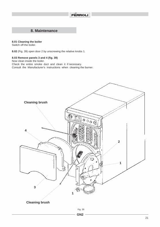
8.01 Cleaning the boilerSwitch off the boiler.
8.02 (Fig. 39) open door 2 by unscrewing the relative knobs 1.
8.03 Remove panels 3 and 4 (fig. 39)Now clean inside the boiler.Check the entire smoke duct and clean it if necessary.Consult the Manufacturer's instructions when cleaning the burner.
8. Maintenance
Fig. 39
Cleaning brush

22GN2
9.01 Boiler unit
9. Boiler parts
Key1 33004770 FRONT ELEMENT2 33004780 REAR ELEMENT3 33004790 INTERMEDIATE ELEMENT4 33004800 INTERMEDIATE ELEMENT PLUS FEET5 33100740 SMOKEBOX COLLAR6 33202141 UPPER SERVICING DOOR7 33202150 TELLTALE8a 33202170 BOILER BURNER DOOR8b 33202190 BOILER BURNER DOOR9 33400811 SHEATH 1"1/4x235 (5 BULBS)
10 34000610 HEX PLUG11 33601320 11/4 FE00 HEX PLUG12 38443650 FLANGE O. 160x160 THICKNESS 1613 34008930 PLUG M16 FOR DOOR HINGES14 34008940 PLUG 12x50 UNI 171315 34008950 BUSHING M16xM20 FOR SIDES16 34008960 NUT M20 H7 FOR SIDE FIXING17 34010230 PLUG M16x115 FOR HANDLE18 34205080 LINK ID 94.4 ED 100.22 LENGTH 45
19 34300220 CLENCHING SPRING ISO WIRE D. 0.820 34403470 ROD M12x50020 34403480 ROD M12x61020 34403490 ROD M12x72020 34403500 ROD M12x83020 34403510 ROD M12x94020 34403520 ROD M12x105020 34403530 ROD M12x118020 34403540 ROD M12x129020 34403550 ROD M12x140020 34403560 ROD M12x151021 35316450 BURNER DOOR INSULATION D. 392x4522 35316461 SERVICE DOOR INSULATION23 36901140 1/2" NPT CHECK VALVE FOR WATER GAUGE24 37511630 COMPLETE DOOR HANDLE25 34010670 HANDLE M1626a 38008670 COMPLETE BURNER DOOR26b 38008680 COMPLETE BURNER DOOR27 35100180 RUBBER SEAL ED 133 ID 90 THICKNESS 4

23GN2
9-02 Shell
49 37025840 COMPLETE LOWER FRONT PANEL50 36503630 DUAL CORE HITCH FERROLI TYPE51 31000210 MO/A3 PRONG COUPLING CLIP52 31207470 SIDE FIXING BRACKET53 35002420 DISK WITH GROUND SYMBOL54 34000640 FE00 COUPLING PRONG56 35003390 JIG FOR GEARCASE58 36401450 SAFETY KEY LS 541572 C. 1500 110 C59 36401880 C.H. BOILER THERMOSTAT61 36400790 THEMOMANOMETER62 36500200 RUBBER CORE HITCH ART. 302 QVA63 36501900 TERMINAL STRIP OK 432/12-500K/1264 36502651 TERMINAL 1-12 IND.PLATE65 36100290 MAIN SWITCH68 31135920 SPACER69 32911030 SAFETY WIRING BOX70 32911040 SAFETY WIRING CAP
Key
40 37025850 COMPLETE MODULAR SIDE PANEL41a 37029020 COMPLETE RIGHT FRONT SIDE PANEL N° 141b 37029030 COMPLETE RIGHT FRONT SIDE PANEL N° 241c 37029040 COMPLETE RIGHT FRONT SIDE PANEL N° 341d 37029050 COMPLETE RIGHT FRONT SIDE PANEL N° 442a 37028980 COMPLETE LEFT FRONT SIDE PANEL N° 142b 37028990 COMPLETE LEFT FRONT SIDE PANEL N° 242c 37029000 COMPLETE LEFT FRONT SIDE PANEL N° 342d 37029010 COMPLETE LEFT FRONT SIDE PANEL N° 443a 37029060 COMPLETE MODULAR COVER N° 143b 37029070 COMPLETE MODULAR COVER N° 243c 37029080 COMPLETE MODULAR COVER N° 343d 37029090 COMPLETE MODULAR COVER N° 444 37025980 COMPLETE MODULAR COVER N° 545 38509150 CONTROL PANEL WITH INSTRUMENTS46 35005420 BOILER INSTRUMENT PANEL47 37025820 COMPLETE REAR WALL48 37025830 COMPLETE UPPER FRONT PANEL

ALL SPECIFICATIONS SUBJECT TO CHANGE
Stockton Close, Minworth Industrial Park, Minworth, Sutton Coldfield, West Midlands B76 IDHSales: 021/3132030 • Service: 021/3131030 • Fax: 021/3132319
cod.
354
0732
/0
01/9
8