EE091-Digital Technique 4-Th-Inst.pdf
47
SRI LANKA INSTITUTE of ADVANCED TECHNOLOGICAL EDUCATION Training Unit Digital Technique 4 Theory No: EE 091 INDUSTRIETECHNIK INDUSTRIETECHNIK ELECTRICAL and ELECTRONIC ENGINEERING Instructor Manual
Transcript of EE091-Digital Technique 4-Th-Inst.pdf

SRI LANKA INSTITUTE of ADVANCED TECHNOLOGICAL EDUCATION
Training Unit
Digital Technique 4 Theory
No: EE 091
INDUSTRIETECHNIKINDUSTRIETECHNIK
ELECTRICAL and ELECTRONIC ENGINEERING
Instructor Manual

Training Unit
Digital Technique 4
Theoretical Part
No.: EE 091
Edition: 2008 All Rights Reserved Editor: MCE Industrietechnik Linz GmbH & Co Education and Training Systems, DM-1 Lunzerstrasse 64 P.O.Box 36, A 4031 Linz / Austria Tel. (+ 43 / 732) 6987 – 3475 Fax (+ 43 / 732) 6980 – 4271 Website: www.mcelinz.com

1
DIGITAL TECHNIQUE 4
CONTENTS Page
LEARNING OBJECTIVES...................................................................................................3
1 MEMORY .....................................................................................................................4
1.1 General ................................................................................................................4
1.2 RS flip flop with NAND gate (NAND latch) ...........................................................5
1.3 RS-flip flop with NOR gate ...................................................................................6
1.4 Dynamic triggering of memories ..........................................................................7
1.5 Edge- detector .....................................................................................................7
1.6 Edge detector with Preparatory Input Terminal....................................................9
1.7 The dynamic JK-flip flop.....................................................................................10
1.8 JK-Master-Slave-flip flop....................................................................................11
2 TIMING CIRCUITS.....................................................................................................13
2.1 General ..............................................................................................................13
2.2 Shortening of pulse width...................................................................................13
2.3 Lengthening of Pulse width................................................................................14
2.4 Delaying of pulses..............................................................................................14
2.5 Manufacturing systems ......................................................................................15
3 ELECTRONIC COUNTERS, DIVIDERS, REGISTERS .............................................16
3.1 General ..............................................................................................................16
3.2 Asynchronous counters .....................................................................................16
3.2.1 Asynchronous binary forward (count up) counter; modulo 8 (0-7) .................16
3.2.2 Asynchronous binaiv backward (count downt counter; modulo 8 (7-0)..........17
3.2.3 Asynchronous binary forward counter; modulo 5 (0-4) ..................................17
3.2.4 Asynchronous binary forward (count up) decade counter..............................18
3.3 Frequency dividers.............................................................................................18
3.4 Shift register.......................................................................................................18

2
4 CODES.......................................................................................................................20
4.1 General ..............................................................................................................20
4.2 Numeric code topes ...........................................................................................20
4.2.1 Binary code (BCD-code, 8-4-2-1. code).........................................................20
4.2.2 Excess-3-code (Stibitz code) .........................................................................21
4.2.3 Alken code .....................................................................................................21
4.2.4 Gray code.......................................................................................................21
4.2.5 2 out of 5 code (walking code) .......................................................................22
4.2.6 Survey of various codes.................................................................................22
4.3 Alphanumeric codes ..........................................................................................23
4.3.1 ASCII-code.....................................................................................................23
4.3.2 Hex-ASCII-code .............................................................................................24
4.3.3 Perforated paper tape code ...........................................................................24
4.4 Encoder, decoder, dode donverter ....................................................................26

3
DIGITAL TECHNIQUE 4
LEARNING OBJECTIVES
The trainee should...
explain the application of a memory
explain the dynamic triggering of memories
describe the functions of JK- and JK-MS-ff with the help of a truth table
name various generation techniques for Integrated circuits
enumerate types of electronic pulse counters
explain shift registers
explain the term "CODE"
explain the terms "TETRADE" and "PNEUDOTETRADE"
enumerate the different code types and give their characteristics
name three alphanumeric codes
convert decimal numbers into the different codes
decode perforated paper tapes in ISO code

4
DIGITAL TECHNIQUE 4
1 MEMORY
1.1 General
In digital technology, memories are circuits which are able to convert a shortly present
binary signal arbitrarily at the Input and whose contents can be interrogated. There are
several types of circuits whose basic principle is always a bistable device pair. They are
also known as "flip-flop".
1 memory can store 1 bit,
Switching characters and functioning of a memory:
For a short time, signal "1" on A1 Q1 leads "1" signal
Q2 leads "0" signal
For a short time, signal "1" on A2 Q2 leads "1" signal
Q1 leads "0" Signal
In digital technology, the memory Inputs are called "R" and “S".
R = reset - reset Input
S = set - set Input
The memory outputs are called "QR" and "QS".
QR reset output
QS output

5
1.2 RS flip flop with NAND gate (NAND latch)
NAND-Iatch
Truth table
R S QR OS
1 0 1 0
0 1 0 1
1 1 0
0 1
0 0 1 1
Change of signals:
"0" signal on R, "1" signal an S.
QS and B lead "1" signal. QR and A lead "0" signal.
Change of signals:
If "1" signal is on the inputs R and S then the previous condition remains stored.
Change of signals:
If the "0" signal is on inputs then the QR and QS outputs lead the "1" signal.
Operation:
"1" Signal on R causes “'0" signal on
QS.
S and B now have "0" signal.
Output QR leads "1" signal.
R and A have "1" signal -
therefore: output QS has "0" signal.

6
1.3 RS-flip flop with NOR gate
NOR-latch
Truth table
R S QR OS
0 1 0 1
0 1 0 1
0 0 1
1 0
1 1 0 0
Change of signals:
"1" signal on S, "0" signal on R.
QR and A lead "0" signal, therefore: Qs has "1" signal.
B and S lead "1" signal, therefore: QR has "0" signal.
Change of signals:
If a "0" signal is on both inputs, then the previous condition remains stored.
Change of signals:
If a "1" Signal is on both inputs, then the QR and Qs outputs lead the "0" signal.
Operation:
"1" Signal on R causes "0"
signal on QS
S and B also have the "0" signal
and output QR has "1" signal.

7
1.4 Dynamic triggering of memories
Because of the high operating speed of electronic systems and if a suitable design has
been made available, it is possible to set or reset binary storages already at the moment
of signal changes.
1.5 Edge- detector
These elements are connected in series with R-S memories. At the output they transmit a
short signal only if the input signal changes.
E.g.: 0-1 or 1-0
a) Symbol
means, that the circuit triggers when a positive-going
transition signal is applied to the Input signal change of 0-1
Signal diagram

8
b) Symbol
(old ) means that the circuit triggers when a
negative-going signal is applied to the Input (1-0)
Signal diagram

9
1.6 Edge detector with Preparatory Input Terminal
Symbol
Q is "1" when T Input signal changes from "1"
to "0" and V is already "1".
Signal diagram

10
1.7 The dynamic JK-flip flop
This is a special RS-ff where the undesired condition of QR and Qs = 1, and QR and Qs =
0 is prevented.
This is affected by an additional feedback from the output to the Input gates.
Circuit
Truth table
While during RS-NOR-ff in the R = S = 1 status the outputs QR and Qs have led the "0"
signal, the JK-ff changes into another state. This advantage is applied specially for
frequency dividers and counters. This circuit functions only when the Input Signal changes
are dynamic. The dynamic effect is obtained by RC components.
When the JK-ff is used as a flip flop which is supplied with clock pulses then a status
change can be obtained only when T has a "1" signal.
J = dynamic set Input
T = pulse Input
K = dynamic reset
11
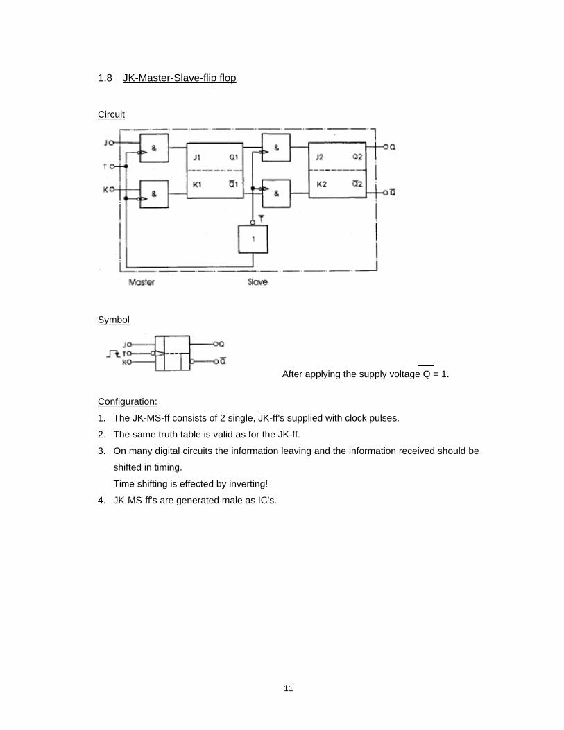
1.8 JK-Master-Slave-flip flop
Circuit
Symbol
After applying the supply voltage Q = 1.
Configuration:
1. The JK-MS-ff consists of 2 single, JK-ff's supplied with clock pulses.
2. The same truth table is valid as for the JK-ff.
3. On many digital circuits the information leaving and the information received should be
shifted in timing.
Time shifting is effected by inverting!
4. JK-MS-ff's are generated male as IC's.

12
Signal diagram
The output of the JK-MS-ff changes the state once in every clock pulse.
NOTE:
After 2 clock pulses the ff has returned to its original status.
Therefore, it is also called a binary counting element or 1:2 translator!

13
2 TIMING CIRCUITS
2.1 General
In digital technique, male monostable trigger elements are used as timing circuits. They
are also called monoflops.
Symbol:
The duration of the output pulse depends on an R-C combination which may be
connected either internally or externally.
A timing circuit can fulfil the following tasks:
2.2 Shortening of pulse width
Input pulses with different pulse widths are shortened so that the output pulses have the
same width.

14
2.3 Lengthening of Pulse width
Output pulses which are longer but which last for the same time are generated from short
input pulses.
2.4 Delaying of pulses
The output pulses should be delayed, but the delay time should always be the same.

15
2.5 Manufacturing systems
DTL-technology:
The IC is built from diodes and transistor = diodes - transistor - logic.
Circuits of this technology are particularly insensitive to faults.
TTL-technology:
Circuits can receive and supply relative big currents without getting particularly
hot = transistor - transistor - logic.
ECL-technology:
Shortest switching times and highest switching frequencies. The transistor emitters are
coupled with each other.
The IC consists of transistor and resistance = emitter-coupled logic.
Analogous IC:
They process continually changing signals (audio-frequency variations). Analogous IC's
are male with 3 to 6 amplifier stages.
Application:
Intermediate frequency amplifiers, radio and 1V sets, mixing stages, filter circuits,
operation amplifiers.
MOS-technology:
Logic modules built from MOS-FET in Integrated technology.
Very low control capacity, high packing density.
COS-MOS-technology:
Also CMOS technology, built from complementary MOS-FET's. Simplified circuit.

16
3 ELECTRONIC COUNTERS, DIVIDERS, REGISTERS
3.1 General
Binary pulses can be counted and displayed with flip flops by counters in any desired time
sequence.
Classification of counters according to
Clock pulses Mode of counting Modulo Code display
forward 3 binary
asynchronous backward 10 BCD
synchronous forward/backward 12 7-segments
pre-selection 16 1 out of 10
Counters, dividers, and registers consist of flip flops connected in series.
A counter is asynchronous when the trigger circuits trigger one after the other
(asynchronously).
The modulo-value indicates the possible counting steps a counter can do.
3.2 Asynchronous counters
The JK-flip flops are used as frequency dividers.
3.2.1 Asynchronous binary forward (count up) counter; modulo 8 (0-7)
The JK-flip flops are switched as clock flip flops (inputs J and K remain open) and operate
as binary counter elements (binary circuit).
For a maximum counting capacity up to 8 (0-7) a total of 3 flip flops are required.

17
3.2.2 Asynchronous binary backward (count down) counter; modulo 8 (7-0)
The flip flops are also switched as clock flip flops, except that Q is used for outputs.
3.2.3 Asynchronous binary forward counter; modulo 5 (0-4)
Since the used flip flops additionally have static reset inputs it is easy to reduce the
counting capacity as opposed to the maximum possible rate.
A binary counter which should count only to 5 also needs 3 flip flops but the counter
reading 5 must be eliminated through an AND gate.
5 = QA = 1, QB = 0, Qc = 1.
When this combination is present all flip flops must be immediately reset. Since this
happens within a very short time this state never occurs; it cancels itself. The counter
counts only to 4.

18
3.2.4 Asynchronous binary forward (count up) decade counter
A decade counter has a counting capacity of 10 (0-9). In digital technique, these, counters
are the ones which are most frequently used.
For a counting capacity of 10, 4 flip flops are needed.
3.3 Frequency dividers
Frequency dividers are a simple form of asynchronous counters. Here, the frequency
divider adds always a defined number of pulses and indicates when the total sum has
been reached,
It then flips back into the zero status.
3.4 Shift register
With the shift register, the entire stored word (number of binary characters) may be shifted
by one line, always per one clock pulse.
E.g.: 5-digit shift register:
(shifting towards the right)

19
Exercise:
Asynchronous forward counter; modulo 1000
- Prepare a logic circuit for an asynchronous forward counter from 0 - 999. The
counter must be resetable to zero at any desired count,
Circuit

20
4 CODES
4.1 General
The term "code" means symbols and their combination which are used for representing of
numbers, letters and words.
For coding of the decimals from 0 to 9 into the binary system, 4 bits are needed (one
tetrade) = 1001.
As 4 bits allow several and different possibilities while a combination of only 0 to 9 is
needed the numbers 10 to 15 will not be used.
These combinations are called pseudotetrads and may be used for the recognition of
errors.
4.2 Numeric code topes
4.2.1 Binary code (BCD-code, 8-4-2-1. code)
This code is based on the binary system. There are two ways of coding multi-digit decimal
numbers:
- straight binary coding:
Example: 243: 1 1 1 1 0 0 1 1
Advantage: simple to calculate
Disadvantage: very complex
- binary-coded-decimal code:
Here, each decimal digit is coded in binaries, and the decimal structure is maintained.
Example: 243: 0010 - 0100 - 0011
This is very easy to understand but is difficult for calculations.

21
4.2.2 Excess-3-code (Stibitz code)
This is a binary code displaced by 3.That means the zero of this code starts from 0011
which is 3 in dual system (see table 4.2.6) Where the combinations 0000, 1111 which can
appear during disturbances, are omitted. Here, they are pseudotetrads and may be used
to recognize errors.
4.2.3 Aiken code
Here, the pseudotetrads are in the centre. The presence of the words 0000 and 1111 is a
disadvantage.
4.2.4 Gray code
What is important in this code is that only one code position changes at the transition of
any two neighbouring code words. It is called a unit-distance- or cyclic code.
It is used for length and angle measuring, with so-called encode rulers and encode disks.
Code disk (angle encoder):

22
4.2.5 2 out of 5 code (walking code)
This is a 5-bit code where two bits are always"1" and three bits always "0".
A logic circuit can easily watch the bit figure (0,1) and can activate an alarm in case of
erroneous numbers.
4.2.6 Survey of various codes
Dec. Dual Excess 3 Aiken Gray 2 out of 5
0 0000 0011 0000 0000 00011
1 0001 0100 0001 0001 00101
2 0010 0101 0010 0011 00110
3 0011 0110 0011 0010 01010
4 0100 0111 0100 0110 01100
5 0101 1000 1011 0111 10100
6 0110 1001 1100 0101 11000
7 0111 1010 1101 0100 01001
8 1000 1011 1110 1100 10001
9 1001 1100 1111 1101 10010
23
4.3 Alphanumeric codes
These are codes whose character set comprises numbers, letters, and special characters.
Usually, they have 5 or 8 bit for each character.
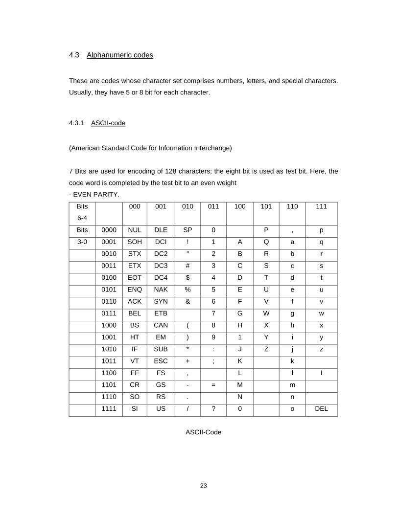
4.3.1 ASCII-code
(American Standard Code for Information Interchange)
7 Bits are used for encoding of 128 characters; the eight bit is used as test bit. Here, the
code word is completed by the test bit to an even weight
- EVEN PARITY.
Bits
6-4
000 001 010 011 100 101 110 111
Bits 0000 NUL DLE SP 0 P , p
3-0 0001 SOH DCI ! 1 A Q a q
0010 STX DC2 " 2 B R b r
0011 ETX DC3 # 3 C S c s
0100 EOT DC4 $ 4 D T d t
0101 ENQ NAK % 5 E U e u
0110 ACK SYN & 6 F V f v
0111 BEL ETB 7 G W g w
1000 BS CAN ( 8 H X h x
1001 HT EM ) 9 1 Y i y
1010 IF SUB * : J Z j z
1011 VT ESC + ; K k
1100 FF FS , L l I
1101 CR GS - = M m
1110 SO RS . N n
1111 SI US / ? 0 o DEL
ASCII-Code

24
4.3.2 Hex-ASCII-code
A hexadecimal character which is encoded in the ASCII code stands for each tetrad of the
dual word.
(hexadecimal system or sedecimal system = system of 16).
For the numbers 0 to 9, also the symbols 0 to 9 are used; from 10 to 15 the letters A to F
are used.
Dec.: 0 1 2 3 4 5 6 7 8 9 10 11 12 13 14 15
Hex. : 0 1 2 3 4 5 6 7 8 9 A B C D E F
Example: 1100 0100 - 8 bit data word
C 4 - hexadeclmal coding
1000011 0110100 - ASCII coding of the
hexadecimal representation
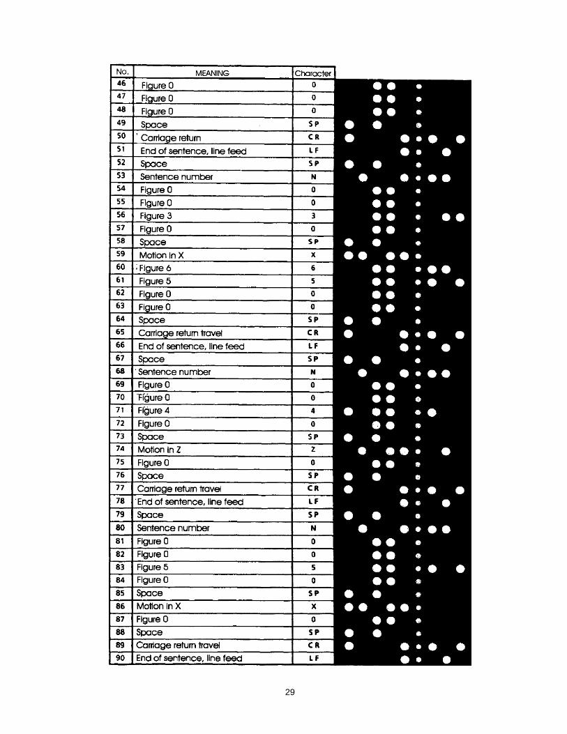
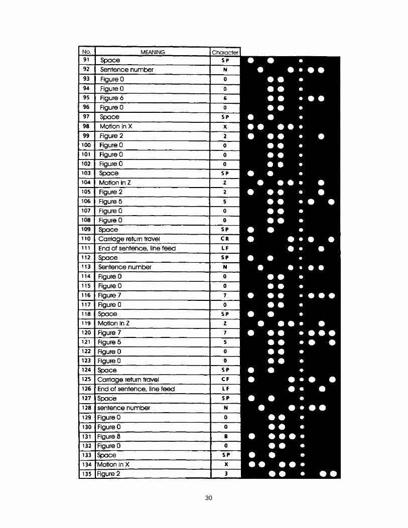
4.3.3 Perforated paper tape code
This is also a 7 bit code with a test bit - EVEN PARITY - and with a feed Crack. It is used
mainly for NC controls.
EVEN PARITY - even number of holes
FEED TRACK - feed track
ODD PARITY - odd number of holes.

25
Code table for perforated paper tape according to DIN and /or ISO:

26
4.4 Encoder, decoder, dode donverter
ENCODERS:
Encoders are logic circuits which convert numbers, letters or characters into any desired
code.
DECODERS:
Decoders are logic circuits which convert a certain code to numbers, letters or characters.
CODE CONVERTERS:
Code converters are logic circuits which convert a certain code to any other desired code.

27
Examples:
1.) Convert the decimal figure 8736 to the
BCD code: 1000 0111 0011 0110
Aiken code: 1110 1101 0011 1100
Excess-3 code 1011 1010 0110 1001
Gray code: 1100 0100 0010 0101
2 of 5 code 10001 01001 01010 11000
2,) Contour description of a workpiece:
- decode the perforated paper tape.
- complete the program.
- draw the contour description and compare the workshop drawing with the
contour description.
Workshop drawing:

28
Perforated paper tape
29
30

31

32

33
Program:
% CR IF
N9030 IF
N10 G94 IF
N20 G01 Z10000 F5000 IF
N30 X6500 IF
N40 ZO IF
N50 XO IF
N60 X2000 Z2500 IF
WO Z7500 IF
N80 X3000 IF
N90 X4500 Z5000 IF
N100 X3000 Z2500 IF
MM X2000 IF
N120 X0 Z0 IF
N130 M30 IF
Contour description:

34
EE 091
Digital Technique 4
Theoretical Test

35
DIGITAL TECHNIQUE 4
TEST 1
1. Draw an RS flip-flop with NOR gate, and prepare truth fable.
2. Draw the output signal Q of this edge -detector, with preparatory Input terminal.
3. Draw the symbol of a JK-MS-ff, which triggers at a positive going transition.
4. Name three tasks which can be fulfilled by monoflops.

36
5. Explain the term "C MOS-technique".
6. Write the classification of the counters.
7. Draw an asynchronous forward decade counter (count up) with reset.
8. An engineman must press a pushbutton at intervals of 60 seconds, in order to
maintain the driving order. If he omits to actuate the pushbutton, an optical signal will
appear for 10 seconds, if the pushbutton is still not actuated during this time, then the
control logic must supply an order to brake the train. (solenoid valve).
Design the appropriate logic circuit.
9. Write the number 8642 using the BCD code.
10. Explain the terms:
- EVEN PARITY.
- ODD PARITY.

37
DIGITAL TECHNIQUE 4
TEST 2
1. Draw the RS flip-flop with NAND gate, and prepare the truth fable.
2. 2 Lamps shall be switched on via two pushbuttons, and both switched off via a third
pushbutton.
Lamp No. 2 cannot be switched on unless lamp No. 1 has already been switched on.
Design a logic scheme.
3. Design a logic circuit for a rotation direction change over switch.
Pushbutton SO = stop, pushbutton S1 = motor anticlockwise rotation,
pushbutton S2 = motor clockwise rotation.
Switching over from anticlockwise to clockwise rotation or vice versa is permitted only
when the motor is at standstill. The run-out time is assumed to be 20 seconds,
38
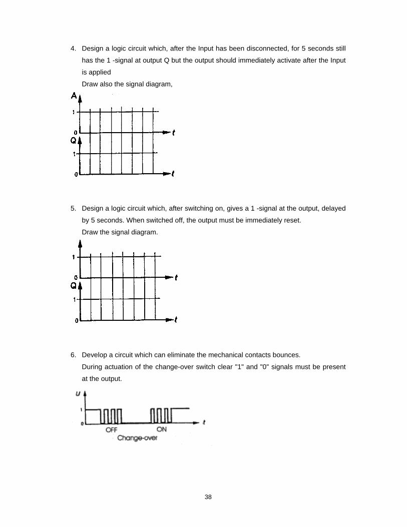
4. Design a logic circuit which, after the Input has been disconnected, for 5 seconds still
has the 1 -signal at output Q but the output should immediately activate after the Input
is applied
Draw also the signal diagram,
5. Design a logic circuit which, after switching on, gives a 1 -signal at the output, delayed
by 5 seconds. When switched off, the output must be immediately reset.
Draw the signal diagram.
6. Develop a circuit which can eliminate the mechanical contacts bounces.
During actuation of the change-over switch clear "1" and "0" signals must be present
at the output.

39
7. Develop a circuit which is able to filter out every fourth pulse.
Complete the truth table and the pulse diagram.
8. Draw an RS flip-flop with dominating setting, that is, resetting is possible only when a
0 signal is present at the setting Input.
9. Give 3 numerical codes and 2 alphanumerical codes.
10. Explain the terms “decoder, encoder, code converter”.

40
DIGITAL TECHNIQUE 4
TEST 1
(Solution)
1.
2.
3.

41
4. Shortening of pulses width
Extending of pulses width
Delaying of pulses
5. Integrated circuits constructed from complementary MOS-FET.
6. Clock pulse: synchronous, asynchronous
Counting mode: forward, backward, forward/backward, pre-selection
Modulo: 3, 5, 10, 16, …
Code display: binary, BCD, 7 segment, 1 out of 10 ....
7.
8.
9.
10. EVEN PARITY - even number of holes
ODD PARITY - odd number of holes
8 6 4 2
1000 0110 0100 0010

42
DIGITAL TECHNIQUE 4
TEST 2
(Solution)
1.
2.
3.

43
4.
5.
6.
7.

44
8.
9. Numerical codes: BCD, Excess 3, Gray, Aiken, …
Alphanumerical codes: ASCII, Hex ASCII, perforated paper tape…
10. Decoder: Converts codes into numbers, letters, and characters
Encoder: Converts numbers, letters and characters into codes
Code converter: Converts codes into other codes.
45
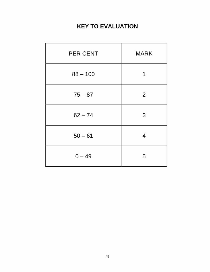
KEY TO EVALUATION
PER CENT
MARK
88 – 100
1
75 – 87
2
62 – 74
3
50 – 61
4
0 – 49
5