Installation and Configuration - Spectralink...
23
March 2012 Edition 1725-36120-001 Version H SpectraLink ® 6100 MCU Open Applications Interface (OAI) Gateway Installation and Configuration SpectraLink 6000 System
Transcript of Installation and Configuration - Spectralink...

March 2012 Edition 1725-36120-001 Version H
SpectraLink® 6100 MCU Open Applications Interface (OAI) Gateway
Installation and Configuration SpectraLink 6000 System
SpectraLink 6100 MCU: OAI Gateway: Installation and Configuration: SpectraLink 6000 System
PN: 1725-36120-001_H.doc 2
Patent Information The accompanying product is protected by one or more US and foreign patents and/or pending patent applications held by Polycom, Inc.
Copyright Notice © 1998 to 2012, Polycom, Inc. All rights reserved. POLYCOM®, the Polycom "Triangles" logo and the names and marks associated with Polycom's products are trademarks and/or service marks of Polycom, Inc. and are registered and/or common law marks in the United States and various other countries. All other trademarks are property of their respective owners. No portion hereof may be reproduced or transmitted in any form or by any means, for any purpose other than the recipient's personal use, without the express written permission of Polycom.
All rights reserved under the International and pan-American copyright Conventions.
No part of this manual, or the software described herein, may be reproduced or transmitted in any form or by any means, or translated into another language or format, in whole or in part, without the express written permission of Polycom, Inc.
Do not remove (or allow any third party to remove) any product identification, copyright or other notices.
Every effort has been made to ensure that the information in this document is accurate. Polycom, Inc. is not responsible for printing or clerical errors. Information in this document is subject to change without notice and does not represent a commitment on the part of Polycom, Inc.
Notice Polycom, Inc. has prepared this document for use by Polycom personnel and customers. The drawings and specifications contained herein are the property of Polycom and shall be neither reproduced in whole or in part without the prior written approval of Polycom, nor be implied to grant any license to make, use, or sell equipment manufactured in accordance herewith.
Polycom reserves the right to make changes in specifications and other information contained in this document without prior notice, and the reader should in all cases consult Polycom to determine whether any such changes have been made.
NO REPRESENTATION OR OTHER AFFIRMATION OF FACT CONTAINED IN THIS DOCUMENT INCLUDING BUT NOT LIMITED TO STATEMENTS REGARDING CAPACITY, RESPONSE-TIME PERFORMANCE, SUITABILITY FOR USE, OR PERFORMANCE OF PRODUCTS DESCRIBED HEREIN SHALL BE DEEMED TO BE A WARRANTY BY POLYCOM FOR ANY PURPOSE, OR GIVE RISE TO ANY LIABILITY OF POLYCOM WHATSOEVER.
Contact Information Please contact your Polycom Authorized Reseller for assistance.
Contact Information Please contact your Polycom Authorized Reseller for assistance.
Polycom, Inc. 4750 Willow Road, Pleasanton, CA 94588 http://www.polycom.com
PN: 1725-36120-001_H.doc 3
About this Guide SpectraLink’s Open Application Interface (OAI) enables third-party computer applications to communicate with SpectraLink Wireless Telephones. This document explains installation of the SpectraLink 6100 OAI Gateway (MOG 500) by Polycom. The installation process connects the OAI Gateway to an existing SpectraLink 6100 MCU.
Polycom Model Numbers This document covers the following registered model numbers:
SCA416, SCA408, SCA516, SCC408, SCC416, SCD408, SCD416, SCE408, SCE416, SCF4089, SCF416, SCI408, SCI416, SCJ408, SCJ416, SCK408, SCK416, SCL408, SCL416, SCM408, SCM416, SCN408, SCN416, SCO408, SCO416, SCS416, SCT416, SCX416 RCC400, RCO400, RCU100, RCU200, RCU201, MOG400
Related Documents SpectraLink 6100 MCU: Facility Preparation (1725-36096-001)
SpectraLink 6100 MCU: Installation and Operation (1725-36097-001)
SpectraLink 6100 MCU: Quick Reference (1725-36098-001)
Installing the Outdoor Base Station (1725-36127-001)
Available at http://www.polycom.com/support/voice/proprietary_wireless/index.html
LinkPlus Interface Guide (7125-361xx-001 where xx indicates a number corresponding to the type of PBX)
Available at http://www.polycom.com/support/voice/wi-fi/pbx_integration.html
SpectraLink 6100 MCU: OAI Gateway: Installation and Configuration: SpectraLink 6000 System
PN: 1725-36120-001_H.doc 4
Customer Support Polycom wants you to have a successful installation. If you have questions please contact the Customer Support Hotline at 1-888-POLYCOM (1-888-765-9266).
The hotline is open Monday through Friday, 6 a.m. to 6 p.m. Mountain time.
For Technical Support: [email protected]
For Knowledge Base: http://www.polycom.com/usa/en/support/voice/voice.html
For Return Material Authorization: [email protected]
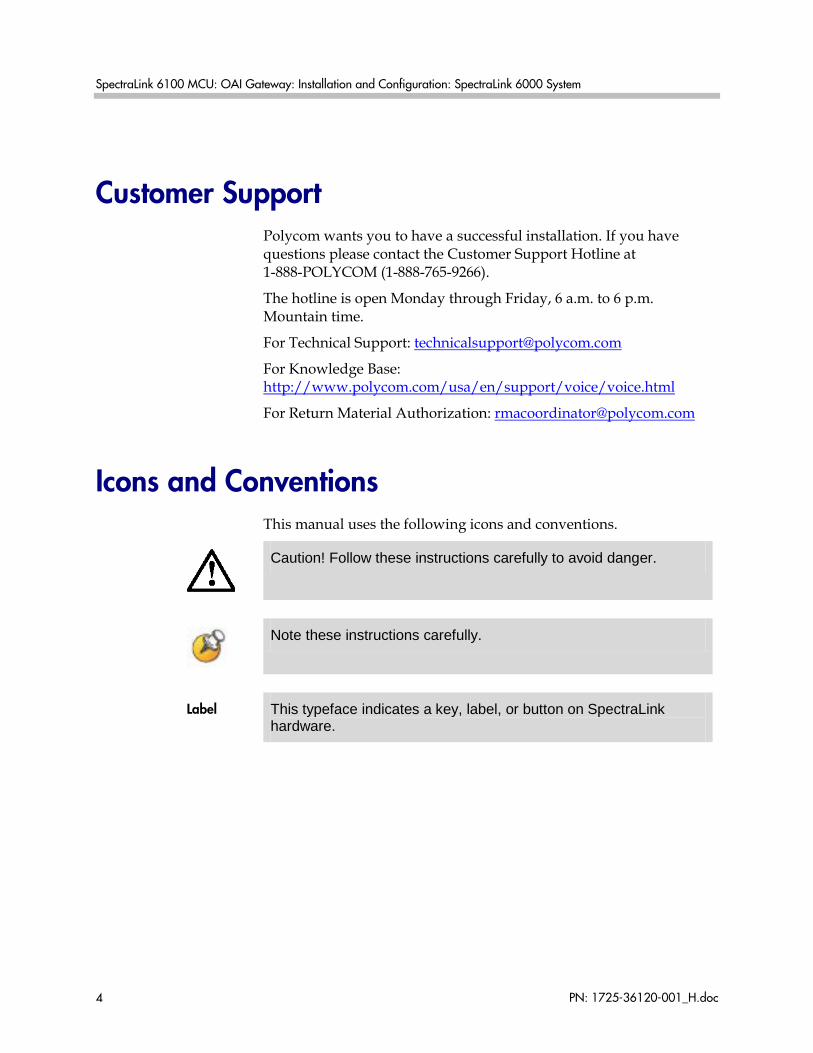
Icons and Conventions This manual uses the following icons and conventions.
Caution! Follow these instructions carefully to avoid danger.
Note these instructions carefully.
Label This typeface indicates a key, label, or button on SpectraLink
hardware.
PN: 1725-36120-001_H.doc 5
Contents
0 About this Guide ..................................................................... 3
Polycom Model Numbers ..................................................................3
Related Documents .............................................................................3
Customer Support ...............................................................................4
Icons and Conventions .......................................................................4
1 Installation Overview ............................................................... 7
2 OAI Overview ......................................................................... 9
System Diagram ..................................................................................9
The OAI Gateway’s Front Panel .....................................................10
3 Installing the OAI Gateway .................................................... 11
Mount OAI Gateway to Wall ..........................................................11
Conduct Power On Test ...................................................................13
Connect OAI Gateway to MCU ......................................................13
Connect OAI Gateway to Application Server ...............................15
4 Assign OAI Function Key ........................................................ 17
5 Certification Test .................................................................... 19
6 Troubleshooting ..................................................................... 21
7 Safety Notices ....................................................................... 23

PN: 1725-36120-001_H.doc 7
Installation Overview Installation has three phases. In some cases, a separate person is responsible for each phase. It is important to coordinate the activities among the persons involved.
1. Site Preparation: Done by the customer or a wire technician/contractor.
2. OAI Gateway Installation: Done by the customer or Polycom.
3. System Certification: Done after installation to confirm the system is working properly.
For more information about Link system architecture and components, please see SpectraLink 6100 MCU: Installation and Operation.
1


PN: 1725-36120-001_H.doc 9
OAI Overview The OAI Gateway (MOG 500) allows the SpectraLink 6100 MCU to interface with an application server as shown in the diagram below. This enables third-party applications to communicate directly with the SpectraLink 6100 MCU, allowing users to retrieve and respond to information using SpectraLink 6000 Wireless Telephones, or handsets. A single OAI Gateway is connected to a SpectraLink 6100 MCU using an inter-processor communication (IPC) cable (8-conductor cable with RJ-45 connectors).
System Diagram
2

SpectraLink 6100 MCU: OAI Gateway: Installation and Configuration: SpectraLink 6000 System
PN: 1725-36120-001_H.doc 10
The OAI Gateway’s Front Panel The OAI Gateway’s front panel has the following status indicators.
• ERROR: Indicates an internal error
• STATUS LEDS:
— LED 1: Future use
— LED 2: Future use
— LED 3/IPC: Indicates the status of the communication between the OAI Gateway and the other MCUs.
— LED 4/RD: Indicates the OAI Gateway is receiving data on the RS-232 port.
— LED 5/SD: Indicates the OAI Gateway is sending data on the RS-232 port.
— PWR: Indicates status of DC power connection.
PN: 1725-36120-001_H.doc 11
Installing the OAI Gateway If this is a new system installation, secure the OAI Gateway to the wall, power up and test the OAI Gateway when the MCUs are tested. Connect the OAI Gateway to the MCU after the Base Stations are installed.
If you are adding the OAI Gateway to an existing system, the system will need to be shut down and re-set after installation of the OAI Gateway. Notify users that the system will be out of service during the installation.
This unit must be installed by a service person familiar with the installation of electronic equipment.
Do not power up the unit before it has been properly grounded to a protective earth. See Grounding instructions below.
Polycom recommends an operational temperature range of 0º– 40º C (31º–104º F). Optimal temperature is 20º C (68º F). Humidity recommendation is 20%– 80% (non-condensing).
Mount OAI Gateway to Wall Like the MCU, the OAI Gateway is designed to be mounted on a backboard of 3/4” plywood, securely fastened to the wall. Mount the OAI Gateway vertically, adjacent to the last MCU. Do not stack the MCUs or OAI Gateway on top of one another.
To mount the OAI Gateway:
1. Using a 1/8” drill bit, drill four pilot holes, on 2” x 12.1” centers.
2. In each pilot hole, sandwich a star washer between the ESD bonding strap and the backboard, then insert the screw (#8 panhead wood screw, 3/4” long) and tighten it, leaving approximately 1/8” to 1/4” gap from the wall.
3. Slide the OAI Gateway over the screw until it drops in place.
4. Tighten screws fully.
3
SpectraLink 6100 MCU: OAI Gateway: Installation and Configuration: SpectraLink 6000 System
PN: 1725-36120-001_H.doc 12
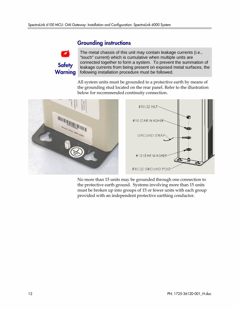
Grounding instructions
Safety Warning
The metal chassis of this unit may contain leakage currents (i.e., "touch" current) which is cumulative when multiple units are connected together to form a system. To prevent the summation of leakage currents from being present on exposed metal surfaces, the following installation procedure must be followed.
All system units must be grounded to a protective earth by means of the grounding stud located on the rear panel. Refer to the illustration below for recommended continuity connection.
No more than 15 units may be grounded through one connection to the protective earth ground. Systems involving more than 15 units must be broken up into groups of 15 or fewer units with each group provided with an independent protective earthing conductor.
Installing the OAI Gateway
PN: 1725-36120-001_H.doc
13
Conduct Power On Test
Use only the provided Class II AC Adapter with output 24Vdc, 1A, 24W.
Use an outlet strip with a built-in power switch to allow the MCU(s) and OAI Gateway to be turned on and off together.
1. Once the units have been properly grounded, connect the power plug from the OAI Gateway’s power adapter to the jack labeled PWR on the OAI Gateway box.
2. Plug the power adapter into an 110V AC outlet or outlet strip.
3. Apply power to the OAI Gateway. The PWR LED on the front panel should come on. All other LEDs should be off.
If the ERROR LED comes on at any time, there is a hardware problem. Note which other LEDs are on (if any) and contact Polycom Customer Service.
4. Verify that leakage current ("touch" current) is below 250 μA rms on exposed metal surfaces.
5. If leakage is excessive, power off the system and re-verify ground path continuity.
Connect OAI Gateway to MCU 1. The OAI Gateway must be connected as the last box in the MCU
chain. Connect the OAI Gateway to the OUT port on the MCU, using the IPC cable supplied.
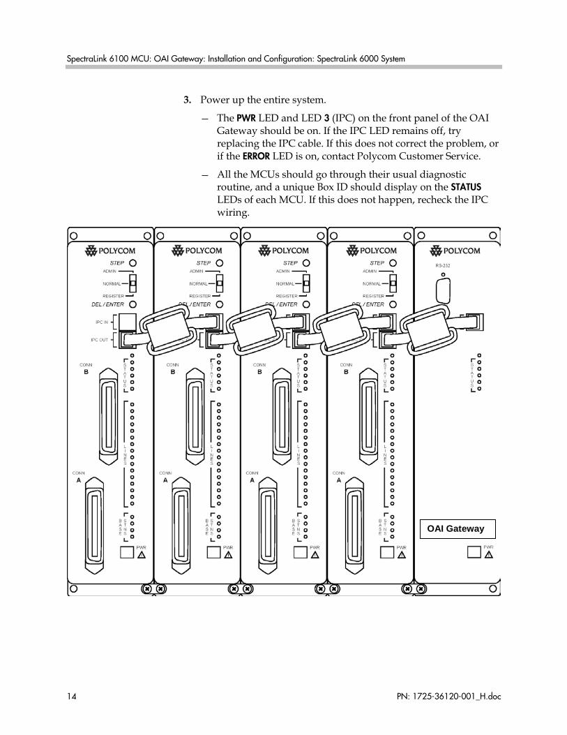
2. Double-check that the IN and OUT ports are correctly connected on all MCUs. The first MCU will have no connection to the IN port; the last MCU is connected to the OAI Gateway. The diagram below shows a chain of four MCUs and the OAI Gateway.
Do NOT stack the MCUs and OAI Gateway on top of each other. Units should be placed side by side physically touching the adjacent unit.
SpectraLink 6100 MCU: OAI Gateway: Installation and Configuration: SpectraLink 6000 System
PN: 1725-36120-001_H.doc 14
3. Power up the entire system.
— The PWR LED and LED 3 (IPC) on the front panel of the OAI Gateway should be on. If the IPC LED remains off, try replacing the IPC cable. If this does not correct the problem, or if the ERROR LED is on, contact Polycom Customer Service.
— All the MCUs should go through their usual diagnostic routine, and a unique Box ID should display on the STATUS LEDs of each MCU. If this does not happen, recheck the IPC wiring.
OAI Gateway
Installing the OAI Gateway
PN: 1725-36120-001_H.doc
15
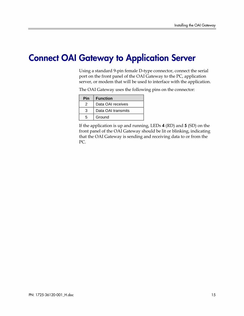
Connect OAI Gateway to Application Server Using a standard 9-pin female D-type connector, connect the serial port on the front panel of the OAI Gateway to the PC, application server, or modem that will be used to interface with the application.
The OAI Gateway uses the following pins on the connector:
Pin Function 2 Data OAI receives 3 Data OAI transmits 5 Ground
If the application is up and running, LEDs 4 (RD) and 5 (SD) on the front panel of the OAI Gateway should be lit or blinking, indicating that the OAI Gateway is sending and receiving data to or from the PC.

PN: 1725-36120-001_H.doc 17
Assign OAI Function Key To access the OAI application, the user presses the FCN key and an assigned number key. Follow these steps to assign a function key to initiate the OAI application.
1. Make sure a handset is registered to LINE 2. This is the only port with administration access.
2. With the system up and running and within range of a Base Station, move the mode switch on the MCU to the ADMIN position.
3. Press START on the handset registered to LINE 2. You should hear a steady tone.
4. Press the FCN key followed by the key you want to assign for OAI access.
5. Press ##555, then press END. This assigns OAI to the specified key.
6. Return the MCU mode switch to the NORMAL position.
The OAI macro can be programmed to more than one key sequence to support multiple OAI functions within the same application. The application must then be able to distinguish which key sequence is assigned to which function.
4

PN: 1725-36120-001_H.doc 19
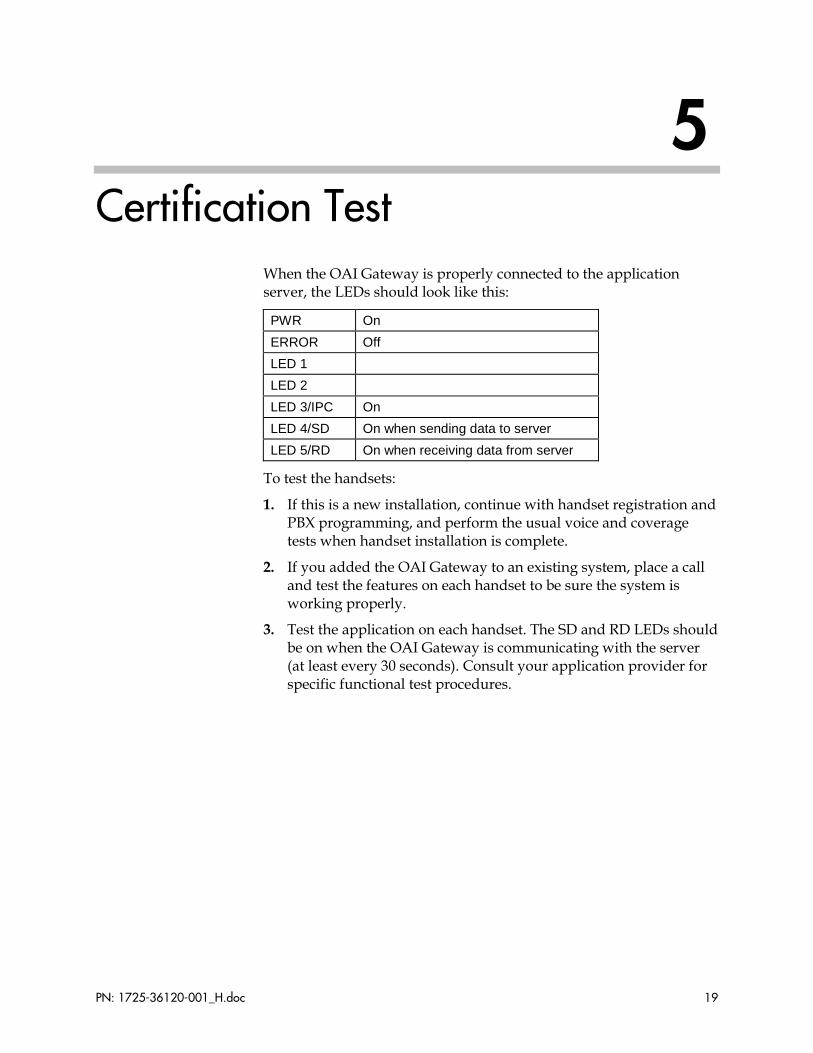
Certification Test When the OAI Gateway is properly connected to the application server, the LEDs should look like this:
PWR On ERROR Off LED 1 LED 2 LED 3/IPC On LED 4/SD On when sending data to server LED 5/RD On when receiving data from server
To test the handsets:
1. If this is a new installation, continue with handset registration and PBX programming, and perform the usual voice and coverage tests when handset installation is complete.
2. If you added the OAI Gateway to an existing system, place a call and test the features on each handset to be sure the system is working properly.
3. Test the application on each handset. The SD and RD LEDs should be on when the OAI Gateway is communicating with the server (at least every 30 seconds). Consult your application provider for specific functional test procedures.
5

PN: 1725-36120-001_H.doc 21
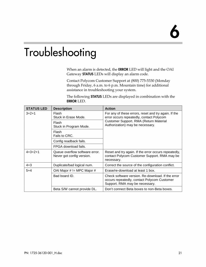
Troubleshooting When an alarm is detected, the ERROR LED will light and the OAI Gateway STATUS LEDs will display an alarm code.
Contact Polycom Customer Support at (800) 775-5330 (Monday through Friday, 6 a.m. to 6 p.m. Mountain time) for additional assistance in troubleshooting your system.
The following STATUS LEDs are displayed in combination with the ERROR LED.
STATUS LED Description Action 3+2+1 Flash
Stuck in Erase Mode. For any of these errors, reset and try again. If the error occurs repeatedly, contact Polycom Customer Support. RMA (Return Material Authorization) may be necessary.
Flash Stuck in Program Mode. Flash Fails to CRC. Config readback fails. FPGA download fails.
4+3+2+1 Queue overflow software error. Never got config version.
Reset and try again. If the error occurs repeatedly, contact Polycom Customer Support. RMA may be necessary.
4+3 Duplicate/bad logical num. Correct the source of the configuration conflict. 5+4 OAI Major # != MPC Major # Erase/re-download at least 1 box.
Bad board ID. Check software version. Re-download. If the error occurs repeatedly, contact Polycom Customer Support. RMA may be necessary.
Beta S/W cannot provide DL. Don’t connect Beta boxes to non-Beta boxes.
6

PN: 1725-36120-001_H.doc 23
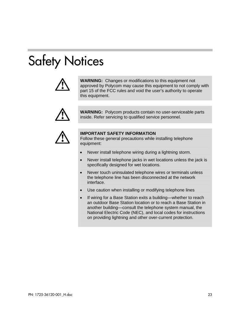
Safety Notices
WARNING: Changes or modifications to this equipment not approved by Polycom may cause this equipment to not comply with part 15 of the FCC rules and void the user’s authority to operate this equipment.
WARNING: Polycom products contain no user-serviceable parts inside. Refer servicing to qualified service personnel.
IMPORTANT SAFETY INFORMATION Follow these general precautions while installing telephone equipment:
• Never install telephone wiring during a lightning storm.
• Never install telephone jacks in wet locations unless the jack is specifically designed for wet locations.
• Never touch uninsulated telephone wires or terminals unless the telephone line has been disconnected at the network interface.
• Use caution when installing or modifying telephone lines
• If wiring for a Base Station exits a building—whether to reach an outdoor Base Station location or to reach a Base Station in another building—consult the telephone system manual, the National Electric Code (NEC), and local codes for instructions on providing lightning and other over-current protection.