
Inspur Server Mother oard Design Scheme rane Mountain Rev 0
21
Inspur Server Mother Board Design Scheme Crane Mountain Rev 0.1 Author: Inspur Crane Mountain Team
Transcript of Inspur Server Mother oard Design Scheme rane Mountain Rev 0

Inspur Server Mother Board Design Scheme
Crane Mountain
Rev 0.1
Author:
Inspur Crane Mountain Team

1. Revision History
Version Date Description
0.1 5/14/2019 Initial Release
Note: Because the product version upgrade or other reasons, the contents of this
document will not be updated on a regular basis. Unless otherwise agreed, this document
used only as a guide, in this document, all statements, information and advice does not
constitute any express or implied guarantees.

LICENSE Contributor (corporate name):
Inspur Electronic Information Industry Co. Ltd, and Intel Corporation ___________________________________________________________ Contributor (contact information):
[email protected] Email Address: ___________________________________________________________
47451 Fremont Blvd, Fremont, CA 94538 Mailing Address: ___________________________________________________________
BY SIGNING BELOW, I CERTIFY THAT I AM AUTHORIZED TO EXECUTE THE OPEN COMPUTE PROJECT LICENSE AGREEMENT ON BEHALF OF THE CONTRIBUTOR NAMED ABOVE, THAT THE CONTRIBUTOR ABOVE IS BOUND BY THE OPEN COMPUTE PROJECT LICENSE AGREEMENT, AND THAT ALL PROMISES MADE HEREIN RELATING TO THE CONTRIBUTIONS OR THE SPECIFICATIONS ARE COMMITMENTS OF THE CONTRIBUTOR.
Open Compute Project Contribution License Agreement
Form of Appendix
Name of Proposed Specification:
High Density Cloud Optimized Platform 2U4S (Crane Mountain) Contribution (e.g. Entire proposed Specification, or portion of proposed specification):
Entire proposed L6 specification for the first ever 4 socket platform – excluding Intel
Chipset IP
Contributor (corporate name): Inspur Electronic Information Industry Co. Ltd, and Intel Corporation
Contributor (contact information):
[email protected] Email Address: ___________________________________________________________
47451 Fremont Blvd, Fremont, CA 94538 Mailing Address: ___________________________________________________________
___________________________________________________________
BY SIGNING BELOW, I CERTIFY THAT I AM AUTHORIZED TO EXECUTE THE OPEN COMPUTE PROJECT LICENSE AGREEMENT ON BEHALF OF THE CONTRIBUTOR NAMED ABOVE, THAT THE CONTRIBUTION AND CONTRIBUTOR ABOVE ARE BOUND BY THE OPEN COMPUTE PROJECT LICENSE AGREEMENT, AND THAT ALL PROMISES MADE HEREIN RELATING TO THE CONTRIBUTION OR THE SPECIFICATION ARE COMMITMENTS OF THE CONTRIBUTOR.

Open Compute Project Contribution License Agreement
Appendix A-1
Name of Proposed Specification:
High Density Cloud Optimized Platform 2U4S (Crane Mountain) __________________________________________________________
Contribution (e.g. Entire proposed Specification, or portion of proposed specification):
Entire proposed L6 specification for the first ever 4 socket platform – excluding Intel Chipset IP ___________________________________________________________
Contributor (corporate name): Entire proposed L6 specification for the first ever 4 socket platform – excluding Intel Chipset IP
___________________________________________________________
Contributor (contact information):
Email Address:
[email protected] ___________________________________________________________
Mailing Address: 47451 Fremont Blvd, Fremont, CA 94538 ___________________________________________________________
BY SIGNING BELOW, I CERTIFY THAT I AM AUTHORIZED TO EXECUTE THE OPEN COMPUTE PROJECT LICENSE AGREEMENT ON BEHALF OF THE CONTRIBUTOR NAMED ABOVE, THAT THE CONTRIBUTION AND CONTRIBUTOR ABOVE ARE BOUND BY THE OPEN COMPUTE PROJECT LICENSE AGREEMENT, AND THAT ALL PROMISES MADE HEREIN RELATING TO THE CONTRIBUTION OR THE SPECIFICATION ARE COMMITMENTS OF THE CONTRIBUTOR.


Crane Mountain
7 May, 2019
2. Scope
This standard provides the reference board-specific information detailing the features and
functionality of a general purpose 4-socket server board for adoption by the Open Compute
Project community. The purpose of this document is to define four socket server board that is
capable of deployment in scale out data centers as well as traditional data centers with 19”
rack enclosures. In the creation of the Crane Mountain specification, considerations are made
for 4-socket server boards that were in production at time of specification release that would
fulfill these needs.
This document is not intended to be used solely as a basis for a procurement of OCP
compatible products. The OCP community may have additional requirements. These
incremental requirements can be captured in additional procurement documentation.
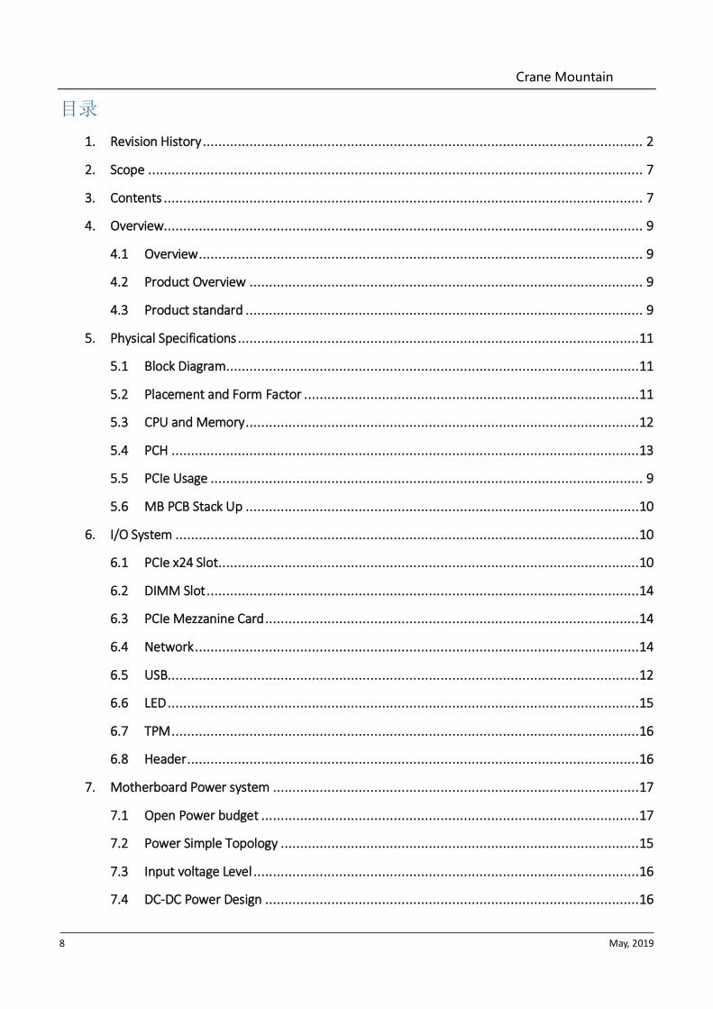
3. Contents
Crane Mountain
8 May, 2019
目录
1. Revision History ................................................................................................................. 2
2. Scope ............................................................................................................................... 7
3. Contents ........................................................................................................................... 7
4. Overview........................................................................................................................... 9
4.1 Overview .................................................................................................................. 9
4.2 Product Overview ..................................................................................................... 9
4.3 Product standard ...................................................................................................... 9
5. Physical Specifications .......................................................................................................11
5.1 Block Diagram ..........................................................................................................11
5.2 Placement and Form Factor ......................................................................................11
5.3 CPU and Memory .....................................................................................................12
5.4 PCH ........................................................................................................................13
5.5 PCIe Usage ............................................................................................................... 9
5.6 MB PCB Stack Up .....................................................................................................10
6. I/O System .......................................................................................................................10
6.1 PCIe x24 Slot ............................................................................................................10
6.2 DIMM Slot ...............................................................................................................14
6.3 PCIe Mezzanine Card ................................................................................................14
6.4 Network ..................................................................................................................14
6.5 USB.........................................................................................................................12
6.6 LED .........................................................................................................................15
6.7 TPM ........................................................................................................................16
6.8 Header ....................................................................................................................16
7. Motherboard Power system ..............................................................................................17
7.1 Open Power budget .................................................................................................17
7.2 Power Simple Topology ............................................................................................15
7.3 Input voltage Level ...................................................................................................16
7.4 DC-DC Power Design ................................................................................................16

Crane Mountain
9 May, 2019
8. BMC ................................................................................................................................17
8.1 Main Feature ..............................................................................................................17
8.2 Integrated BMC Hardware ............................................................................................18
9. Thermal Design Requirements ...........................................................................................19
9.1 Thermal kit requirements .........................................................................................19
9.2 Environmental and Regulations..................................................................................20
10. Labels and Markings ...........................................................................................................21
10.1 Labels .......................................................................................................................21
10.2 Markings ...................................................................................................................21
4. Overview
4.1 Overview
Crane Mountain is based on Intel® Cascade Lake-SP CPU architecture. The motherboard
supports up to 48 DIMMs. Crane Mountain is designed in the Q1 of 2019.
4.2 Product Overview
Crane Mountain is a completely independent research and development of server
products. Based on Intel® Cascade Lake-SP CPU architecture, using Lewisburg chipset.
Support four mainstream Intel Xeon Cascade Lake-SP 82xx/62xx/52xx series processors.
Support 48 DIMMs DDR4 memory, the biggest support to 2933 MHZ. PCI Express support
expansion slot X24. Supports OCP MEZZ connecter A, B and C.
4.3 Product standard (BOLD & Underline is MUST HAVE for Crane Mountain)
CPU
CPU type
Supports four Intel® Cascade Lake-SP
82xx/62xx/52xx series processors (TDP
205W)
Connecter Four Socket-P0 slots

Crane Mountain
10 May, 2019
Chipset
Chipset type Any Lewisburg PCH is acceptable
RAM
RAM type DDR4 ECC RDIMM/LRDIMM/3DS LRDIMM
RAM slot quantity 48
RAM total capacity Total capacity 6144GB(single 128GB)
I/O Connecter
USB Two rear USB 3.0 ports, one on board USB 3.0
port
VGA One rear VGA
UID One ID pilot lamp inlay
Network card
Network card controller Support OCP MEZZ connecter A, B and C.
Manager chipset
Manager chipset
Integrated one independent 1000 Mbps
network interface, specifically for remote
management of IPMI.
PCI Express slot
The motherboard to the system level must
support at least minimum (1) PCIe x16 from
each CPU
Power supply
PSU spec
The whole system adopts three specifications
of PSU, the power is 800/1300/1600W, and
the maximum configuration is 2 power
supplies. According to the system
configuration, the appropriate PSU and PSU
redundancy modes are selected to support
1+1 redundancy under certain configuration
conditions.
Input power The main specifications is 1600W PSU
AC-- 90-264V,NOM-- 100-240V
Crane Mountain
11 May, 2019
DC-- 190-310V, NOM-- 240V
Modular TPM Support MUST HAVE
5. Physical Specifications
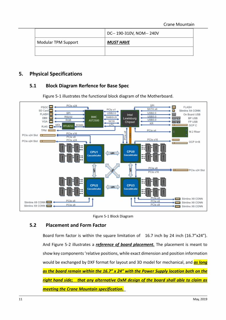
5.1 Block Diagram Rerfence for Base Spec
Figure 5-1 illustrates the functional block diagram of the Motherboard.
Figure 5-1 Block Diagram
5.2 Placement and Form Factor
Board form factor is within the square limitation of 16.7 inch by 24 inch (16.7”x24”).
And Figure 5-2 illustrates a reference of board placement. The placement is meant to
show key components ’relative positions, while exact dimension and position information
would be exchanged by DXF format for layout and 3D model for mechanical, and as long
as the board remain within the 16.7” x 24” with the Power Supply location both on the
right hand side; that any alternative OxM design of the board shall able to claim as
meeting the Crane Mountain specification.

Crane Mountain
12 May, 2019
Figure 5-2 Reference Placement
5.3 CPU and Memory
5.3.1 CPU
The motherboard supports all Intel® Cascade Lake -SP processors with TDP up to
205W.
⚫ Support four Cascade Lake-SP processors up to 205W TDP.
⚫ Three full-width Intel UPI links up to 10.4 GT/s/direction for Cascade Lake-SP
processor.
⚫ Up to 28 cores per CPU (up to 56 threads with Hyper-Threading Technology).
⚫ Single Processor mode and Two-CPU mode are both supported
5.3.2 DIMM
The motherboard has DIMM subsystem designed as below:
⚫ DDR4 direct attach memory support on CPU0, CPU1, CPU2 and CPU3.
⚫ 6x channels DDR4 registered memory interface on each CPU

Crane Mountain
13 May, 2019
⚫ 2x DDR4 slots on each Chanel (total 48x DIMMs)
⚫ Support DDR4 speeds up to 2933MT/s 1DCP, 2666MT/s 2DCP
⚫ Support RDIMMs, LRDIMMs , or 3DS LRDIMMs
⚫ Support SR, DR, QR and 8R DIMMs
⚫ Up to maximum 6144 GB with 128 GB DRAM DIMM
⚫ Follow updated JEDEC DDR4 specification with 288 pin DIMM socket
⚫ Memory support matrix for DDR4 is as Table 5-1
2 Slots Per Channel
1 DIMM Per Channel 2 DIMM per Channel
2933 MT/s 2666 MT/s
Table 5-1
5.3.3 DCPMM
Board and system design support Intel® Optane™ DC persistent memory with 128G,
256G and 512G. Max, 24 DCPMMs with ADR function.
5.4 PCH
The motherboard uses Intel® Lewisburg chipset, which supports following features:
⚫ 2x rear USB3.0 ports, 1x on board USB3.0 port;
⚫ 1x slimline x4 connector use for SATA 0-3;
⚫ 1x slimline x8 connector use for M.2 Riser Board(PCIe X4 Colay with SATA);
⚫ LPC interface, mux with BMC to enable BMC the capability to perform BIOS upgrade
and Recovery
⚫ LPC and SPI interface for TPM header
⚫ SMBUS interface (master & slave)
⚫ Intel® Server Platform Services (SPS) 4.0 Firmware with Intel® Node Manager
⚫ PECI access to CPU
⚫ SMLink0 connect to BMC
⚫ Intel® Manageability Engine (ME) obtain HSC PMBus related information directly.
⚫ Intel® ME SMLink1 connects to Hot swap controller PMBus interface by default.
⚫ BMC connected to HSC PMBus, so it masters HSC PMBus related feature flexibly.

Crane Mountain
14 May, 2019
⚫ Temperature sensors reading from BMC
⚫ PCH SKUs
⚫ Board design shall support all PCH SKUs in terms of power delivery and thermal
design.
5.5 DIMM Slot
Total 48 DIMMs, DIMM 1 are Black, DIMM0 are White.
CPU
Channel 3 D
IMM
0C
hannel 3 D
IMM
1
Channel 4 D
IMM
0
Channel 4 D
IMM
1
Channel 5 D
IMM
0C
hannel 5 D
IMM
1
Channel 0
DIM
M0
Channel 0
DIM
M1
Channel 1
DIM
M0
Channel 1
DIM
M1
Channel 2
DIM
M0
Channel 2
DIM
M1
Figure 6-2 DIMM Topology
5.6 PCIe Mezzanine Card
The motherboard support OCP A/C Mezz cards. OCP A card has both Connector A and
Connector B, support max PCIe 16x Mezz card.
Connector Pin definition follow the OCP Mezzanine Card 2.0 rev1.0
5.7 Network
5.7.1 Data network
Use Single or Dual Port OCP Mezz cards.
5.7.2 Management network
The motherboard has two options of management network interface for BMC’s
connection. Management network shares data network’s physical interface.
Management connection was independent from data traffic, and OS/driver condition.
a) One dedicated RJ45 port for Board management, driven by BMC through
RMII/NC-SI.
b) One OCP A shared-NIC, driven by BMC through NCSI
Crane Mountain
15 May, 2019
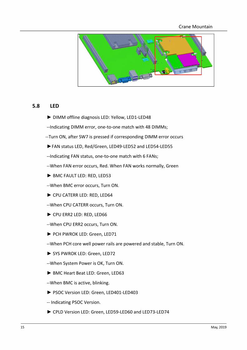
5.8 LED
► DIMM offline diagnosis LED: Yellow, LED1-LED48
--Indicating DIMM error, one-to-one match with 48 DIMMs;
--Turn ON, after SW7 is pressed if corresponding DIMM error occurs
►FAN status LED, Red/Green, LED49-LED52 and LED54-LED55
--Indicating FAN status, one-to-one match with 6 FANs;
--When FAN error occurs, Red. When FAN works normally, Green
► BMC FAULT LED: RED, LED53
--When BMC error occurs, Turn ON.
► CPU CATERR LED: RED, LED64
--When CPU CATERR occurs, Turn ON.
► CPU ERR2 LED: RED, LED66
--When CPU ERR2 occurs, Turn ON.
► PCH PWROK LED: Green, LED71
--When PCH core well power rails are powered and stable, Turn ON.
► SYS PWROK LED: Green, LED72
--When System Power is OK, Turn ON.
► BMC Heart Beat LED: Green, LED63
--When BMC is active, blinking.
► PSOC Version LED: Green, LED401-LED403
-- Indicating PSOC Version.
► CPLD Version LED: Green, LED59-LED60 and LED73-LED74
Crane Mountain
16 May, 2019
-- Indicating CPLD Version.
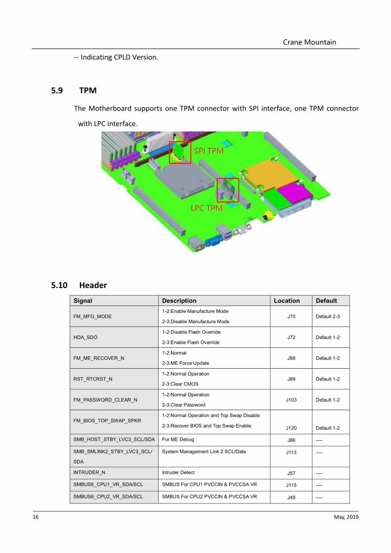
5.9 TPM
The Motherboard supports one TPM connector with SPI interface, one TPM connector
with LPC interface.
5.10 Header
Signal Description Location Default
FM_MFG_MODE 1-2:Enable Manufacture Mode
2-3:Disable Manufacture Mode J70 Default 2-3
HDA_SDO 1-2:Disable Flash Override
2-3:Enable Flash Override J72 Default 1-2
FM_ME_RECOVER_N 1-2:Normal
2-3:ME Force Update J88 Default 1-2
RST_RTCRST_N 1-2:Normal Operation
2-3:Clear CMOS J89 Default 1-2
FM_PASSWORD_CLEAR_N 1-2:Normal Operation
2-3:Clear Password J103 Default 1-2
FM_BIOS_TOP_SWAP_SPKR 1-2:Normal Operation and Top Swap Disable
2-3:Recover BIOS and Top Swap Enable
J120
Default 1-2
SMB_HOST_STBY_LVC3_SCL/SDA For ME Debug J86 ----
SMB_SMLINK2_STBY_LVC3_SCL/
SDA
System Management Link 2 SCL/Data J113 ----
INTRUDER_N Intruder Detect J57 ----
SMBUS6_CPU1_VR_SDA/SCL SMBUS For CPU1 PVCCIN & PVCCSA VR J115 ----
SMBUS6_CPU2_VR_SDA/SCL SMBUS For CPU2 PVCCIN & PVCCSA VR J49 ----
Crane Mountain
17 May, 2019
SMBUS6_CPU3_VR_SDA/SCL SMBUS For CPU3 PVCCIN & PVCCSA VR J65 ----
SMBUS6_CPU4_VR_SDA/SCL SMBUS For CPU4 PVCCIN & PVCCSA VR J114 ----
P5V_HDD_SDA/SCL SMBUS For P5V_HDD VR J52 ----
P3V3_SDA/SCL SMBUS For P3V3 VR J66 ----
6. Motherboard Power system
6.1 Open Power budget
Table 7-1 System Power Budget
7. BMC
BMC is an independent system of host server system. This independent system has its own
processor and memory; The host system can be managed by BMC system even if host hardware
or OS hang or went down.
8.1 Main Feature
⚫ Support IPMI 2.0, IPMI Interface include KCS, LAN, IPMB
⚫ Management Protocol,IPMI2.0, HTTPS, SNMP, Smash CLI
⚫ Web GUI
⚫ Redfish
⚫ Management Network Interface, Dedicated/NCSI
⚫ Console Redirection(KVM) and Virtual Media
⚫ Serial Over Lan(SOL)
⚫ Diagnostic Logs, System Event Log (SEL), Blackbox Log, Audit Log
⚫ Hardware watchdog timer, Fans will full speed when BMC no response in 4 mins
⚫ Intel® Intelligent Power Node Manager 4.0 support
Crane Mountain
18 May, 2019
⚫ Event Alert, SNMP Trap(v1/v2c/v3), Email Alert and Syslog
⚫ Dual BMC firmware image support
⚫ Storage, Monitor RAID Controller/HDD/Virtual HDD
⚫ Firmware update, BMC/BIOS/CPLD
⚫ Device State Monitor and Diagnostic
8.2 Integrated BMC Hardware
ASPEED AST2500 Baseboard Management Controller, at the center of the server management
subsystem is the ASPEED AST2500 integrated Baseboard Management Controller. This device
provides support for many platform functions including system video capabilities, legacy Super
I/O functions, hardware monitoring functions, and incorporates an ARM1176JZF-S 32-bit RISC
CPU microcontroller to host an IPMI 2.0 compliant server management firmware stack.
The following functionality is integrated into the component:
⚫ Baseboard Management Controller (BMC) with peripherals
⚫ Server class Super I/O (SIO)
⚫ Graphics controller
⚫ Remote KVM redirection, USB media redirection, and HW Encryption
The eSPI/LPC interface to the host is used for SIO and BMC communication. The eSPI/LPC Bus
interface provides IPMI Compliant KCS and BT interfaces.
The PCI Express interface is mainly used for the graphics controller interface to communicate
with the host. The graphics controller is a VGA-compliant controller with 2D hardware
acceleration and full bus master support. The graphics controller can support up to 1920x1200
resolution at high refresh rates. The PCI Express interface is also used for BMC messaging to
other system devices using MCTP protocol.
The USB 2.0 Hub interface is used for remote keyboard and mouse, and remote storage support.
BMC supports various storage devices such as CDROM, DVDROM, CDROM (ISO image), floppy
and USB flash disk. Any of the storage devices can be used as a boot device and the host can boot
from this remote media via redirection over the USB interface.
For the main capabilities of the BMC AST2500.BMC provide the 10/100/1000M local RJ45
management connector through RTL8211FD and enable the communication between BMC and
OCP A/PCH with NCSI BUS.

Crane Mountain
19 May, 2019
BMC
RTL8211FDRGMII MDI
RJ45
SWITCH
SWITCHLewisburg
OCP A
NCSI
NCSI
NCSI
Figure 8-1 BMC managerial network topology
8. Thermal Design Requirements
To meet thermal reliability requirement, the thermal and cooling solution should dissipate
heat from the components when system operating at its maximum thermal power. The
thermal solution should be found by setting a high power target for initial design in order to
avoid redesign of cooling solution; however, the final thermal solution of the system should be
most optimized and energy efficient under data center environmental conditions with the
lowest capital and operating costs. Thermal solution should not allow any overheating issue
for any components in system.
8.1 Thermal kit requirements
Heat Sink
The heat sink design should choose to be most optimized design with lowest cost. The
heat sink design should be reliable and the most energy efficient design that satisfies
all the conditions described above.
For normal config, system use 2U heatsink 4PCS; For GPU config, system use 2U
heatsink 2PCS and 1U heatsink 2PCS.

Crane Mountain
20 May, 2019
Figure 9-1 2U heatsink
Figure 9-2 1U heatsink
Thermal sensor
The maximum allowable tolerance of thermal sensors in the motherboard is ±3°C.
Using higher accuracy sensor is preferred.
9.2 Environmental and Regulations
9.2.1 Motherboard high altitude
Operational at 1500 meters above sea level
Non-Operational at 12192 meters above sea level
9.2.2 Motherboard relative humidity
Operating and Storage relative humidity: 10% to 90% (non-condensing)
9.2.3 Motherboard Temperature

Crane Mountain
21 May, 2019
Operating temperature range: -5°Cto +45°C
Storage temperature range: -40°C to +70°C
Transportation temperature range: -40°Cto +70°C (short-term storage)