Fractal Antennae and Coherence 1 Fractal Antennae and Coherence

Manual Version 4, for Axe-Fx III Firmware 12.x — April 2020

Inside Front Cover

i
Declaration of ConformityManufacturer’s Name: Fractal Audio Systems, LLC
Manufacturer’s Address: 4 Wilder Drive, Plaistow, NH 03865 USA
Declares that the product: Product name: Axe-Fx III Product option: None
Conforms to the following Product Specifications:
Safety: EN60065:2014EMC: EN55013:2013
EN55020:2007+A11:2011 EN55024:2010
EN61000-3-2:2014 EN61000-3-3:2013
Supplementary Information: The product herewith complies with the requirements of
the Low Voltage Directive 2006/95/EC and the EMC Directive 2004/108/EC.
Clifford ChasePresident / CEO
January 22, 2018
EMC/EMIThis equipment has been tested and found to comply with the limits for a Class B Digital device, pursuant to part 15 of the FCC rules. These limits are designed to provide reasonable protection against harmful interference in residential installations. This equipment generates, uses and can radiate radio frequency energy and, if not installed and used in accordance with the instructions, may cause harmful interference to radio communications. There is no guarantee that interference will not occur in a particular installation. If this equipment does cause harmful interference to radio or television reception, which can be determined by turning the equipment off and on, the user is encouraged to try to correct the interference by one or more of the following measures:
� Reorient or relocate the receiving antenna.
� Increase the separation between the equipment and receiver.
� Connect the equipment to an outlet on a circuit different from that to which the receiver is connected.
� Consult the dealer or an experienced radio/TV technician for help.

ii
TABLE OF CONTENTS1 INTRODUCTION . . . . . . . . . . . . . . . . . . . . . 1
Welcome to the Axe-Fx III . . . . . . . . . . . . . . 1
Feature Summary . . . . . . . . . . . . . . . . . . . . 2
The Setup menu . . . . . . . . . . . . . . . . . . . . . . 3
Quick Connect Guide . . . . . . . . . . . . . . . . . . 4
Setting Levels . . . . . . . . . . . . . . . . . . . . . . . 5
Humbuster™ Cables . . . . . . . . . . . . . . . . . . . 6
Mono vs. Stereo . . . . . . . . . . . . . . . . . . . . . 6
The Home Page: Presets . . . . . . . . . . . . . . . 7
Intro to the Layout Grid . . . . . . . . . . . . . . . . 8
Intro to Scenes and Channels . . . . . . . . . . . 9
Grid Editing: Quick start . . . . . . . . . . . . . . . 10
Block Editing: Quick start . . . . . . . . . . . . . 10
USB Overview . . . . . . . . . . . . . . . . . . . . . . 11
Fractal-Bot & Axe-Edit III . . . . . . . . . . . . . . 11
Connecting Pedals Directly . . . . . . . . . . . . 12
Global Expression Pedal Setup . . . . . . . . . 13
Global Volume Pedal Setup . . . . . . . . . . . . 13
2 HARDWARE OVERVIEW . . . . . . . . . . . . . . 14
The Front Panel . . . . . . . . . . . . . . . . . . . . . 14
The Rear Panel . . . . . . . . . . . . . . . . . . . . . 16
3 USB . . . . . . . . . . . . . . . . . . . . . . . . . . . . . 18
Computer Integration. . . . . . . . . . . . . . . . . 18
USB Inputs and Outputs. . . . . . . . . . . . . . . 19
Mac OS X System Audio . . . . . . . . . . . . . . 20
USB Re-Amping . . . . . . . . . . . . . . . . . . . . . 21
4 SETTING UP . . . . . . . . . . . . . . . . . . . . . . . 22
General Principles . . . . . . . . . . . . . . . . . . . 22
FRFR/Direct . . . . . . . . . . . . . . . . . . . . . . . . 23
FRFR monitor + FRFR to Front-of-House . . 24
Power Amp & Guitar Speakers . . . . . . . . . . 25
Power Amp & Cab + FRFR/Direct . . . . . . . 26
Four-Cable Method (“4CM”) . . . . . . . . . . . 27
FX Processor only (“Post”) . . . . . . . . . . . . 28
FX Processor only (“Pre”) . . . . . . . . . . . . . 29
Inserting Outboard Gear . . . . . . . . . . . . . . 30
Multi I/O Setups. . . . . . . . . . . . . . . . . . . . . 31
5 PRESETS . . . . . . . . . . . . . . . . . . . . . . . . . 32
Overview . . . . . . . . . . . . . . . . . . . . . . . . . . 32
The Layout Grid . . . . . . . . . . . . . . . . . . . . 33
Working with Blocks . . . . . . . . . . . . . . . . . 33
Connector Cables . . . . . . . . . . . . . . . . . . . 35
Block Inventory . . . . . . . . . . . . . . . . . . . . . 37
Example Preset Grids . . . . . . . . . . . . . . . . 38
Editing Effect Blocks . . . . . . . . . . . . . . . . . 39
Saving Changes . . . . . . . . . . . . . . . . . . . . . 40
Preset CPU Limits . . . . . . . . . . . . . . . . . . . 41
6 SCENES & CHANNELS . . . . . . . . . . . . . . . 42
Overview . . . . . . . . . . . . . . . . . . . . . . . . . . 42
Changing Channels . . . . . . . . . . . . . . . . . . 43
Setting Up Channels . . . . . . . . . . . . . . . . . 43
Selecting Scenes . . . . . . . . . . . . . . . . . . . . 44
The Default Scene . . . . . . . . . . . . . . . . . . . 44
Selecting Scenes & Channels Remotely . . 45
Program Change Mapping . . . . . . . . . . . . . 46
Sending MIDI with Scenes . . . . . . . . . . . . . 46
Scene levels . . . . . . . . . . . . . . . . . . . . . . . . 46
Scenes, Channels & Modifiers . . . . . . . . . . 47
Scene Revert . . . . . . . . . . . . . . . . . . . . . . . 47
7 LEVELING PRESETS . . . . . . . . . . . . . . . . . 48
A Method for Leveling . . . . . . . . . . . . . . . . 49
Block Bypass Levels . . . . . . . . . . . . . . . . . 50

iii
8 BLOCKS GUIDE . . . . . . . . . . . . . . . . . . . . . 51
The Fractal Audio Blocks Guide . . . . . . . . . 51
9 MODIFIERS . . . . . . . . . . . . . . . . . . . . . . . 52
Creating a Modifier . . . . . . . . . . . . . . . . . . 52
Modifier Tutorial: Wah Pedal . . . . . . . . . . . 53
Modifier Tips And Tricks . . . . . . . . . . . . . . 53
Modifier Sources Overview . . . . . . . . . . . . 54
Modifier Parameters . . . . . . . . . . . . . . . . . 55
Internal Controllers . . . . . . . . . . . . . . . . . . 58
Metronome . . . . . . . . . . . . . . . . . . . . . . . . 60
External Controllers . . . . . . . . . . . . . . . . . . 60
Modifiers List . . . . . . . . . . . . . . . . . . . . . . . 60
Tutorial: Scene Controllers . . . . . . . . . . . . 61
10 TEMPO . . . . . . . . . . . . . . . . . . . . . . . . . . 62
Synchronizing Sound Parameters . . . . . . . 63
11 THE TUNER . . . . . . . . . . . . . . . . . . . . . . 64
Advanced Tuner Functions . . . . . . . . . . . . 64
Mini Tuners . . . . . . . . . . . . . . . . . . . . . . . . 65
12 SETUP MENU . . . . . . . . . . . . . . . . . . . . . 66
The Foot Controllers Menu . . . . . . . . . . . . 66
The Global Settings Menu . . . . . . . . . . . . . 66
The I/O Menu . . . . . . . . . . . . . . . . . . . . . . . 69
The IR Capture Utility . . . . . . . . . . . . . . . . . 71
The MIDI/Remote Menu . . . . . . . . . . . . . . . 72
The Utilities Menu . . . . . . . . . . . . . . . . . . . 76
13 FC PROGRAMMING . . . . . . . . . . . . . . . . 77
14 IR CAPTURE . . . . . . . . . . . . . . . . . . . . . . 78
Setup 1: Mic Only . . . . . . . . . . . . . . . . . . . . 79
Setup 2: Mic + Di . . . . . . . . . . . . . . . . . . . . 80
Capturing Impulse Responses . . . . . . . . . . 81
15 ADDITIONAL TOPICS . . . . . . . . . . . . . . . 84
Fractal-Bot . . . . . . . . . . . . . . . . . . . . . . . . . 84
Backing Up & Restoring . . . . . . . . . . . . . . . 84
Firmware Updates . . . . . . . . . . . . . . . . . . . 85
Recovery . . . . . . . . . . . . . . . . . . . . . . . . . . 86
Getting Help . . . . . . . . . . . . . . . . . . . . . . . . 86
Global Blocks . . . . . . . . . . . . . . . . . . . . . . . 87
Performance Control Pages . . . . . . . . . . . 89
Loading User Cabs . . . . . . . . . . . . . . . . . . 91
Axe-Change . . . . . . . . . . . . . . . . . . . . . . . . 92
Shortcuts . . . . . . . . . . . . . . . . . . . . . . . . . . 93
Spillover . . . . . . . . . . . . . . . . . . . . . . . . . . . 94
Sending MIDI . . . . . . . . . . . . . . . . . . . . . . . 95
Frequently Asked Questions . . . . . . . . . . . 97
MIDI Reference Tables . . . . . . . . . . . . . . . . 99
16 SPECIFICATIONS . . . . . . . . . . . . . . . . . 102
MIDI Implementation . . . . . . . . . . . . . . . . 104
WARRANTY . . . . . . . . . . . . . . . . . . . . . . . 105
EULA . . . . . . . . . . . . . . . . . . . . . . . . . . . . 106

iv
Legal Notices Fractal Audio Systems Axe-Fx III Owner’s Manual. Contents Copyright © 2018. All Rights Reserved.
No part of this publication may be reproduced in any form without the express written permission of Fractal Audio Systems.
Fractal Audio, the Fractal Audio Systems logo, Axe-Fx, Humbuster, UltraRes, FASLINK are trademarks of Fractal Audio Systems. Manufacturer names and product names mentioned herein are trademarks or registered trademarks of their respective owners, which are in no way associated with or affiliated with Fractal Audio Systems, LLC. The names are used only to illustrate sonic and performance characteristics.
WARNING: To reduce the risk of fire or electric shock, do not expose this appliance to rain or moisture.
CAUTION: To reduce the risk of fire or electric shock, do not remove screws. There are no user serviceable parts inside. Refer servicing to qualified service personnel.
Important Safety Instructions
1. Obey all warnings on the Axe-Fx III chassis and in this User Guide.2. Keep away from sources of heat such as ducts, registers or appliances that produce heat.3. Connect only to a standard grounded AC outlet of 100–240V, 47–63 Hz.4. Keep the power cord in good condition. Do not kink, bend, or pinch. 5. If the cord becomes damaged, discard and replace it.6. If not using your Axe-Fx III for extended periods of time, disconnect from AC power.7. Protect the unit from rain and excessive moisture.8. Refer servicing to qualified personnel only.9. Stop operation of the unit and obtain service if:
- Liquids or excessive moisture enter the unit. - The unit operates incorrectly or performance is inconsistent or erratic. - The unit has been dropped and/or the enclosure damaged.
10. Prolonged exposure to high volume levels can cause hearing damage and/or loss. The use of hearing protection in high volume situations is recommended.
A Manual for Online and Print Use This manual is intended for use in desktop, tablet, and smart phone readers. It includes clickable links and bookmarks to make navigation and cross-reference easy. We generally recommend against printing, because firmware updates tend to make older manual versions out of date. That said, considerations have been taken for those who prefer paper. You are granted permission to print this PDF for personal use only. A copy center or online printer can print and bind a book for you from the PDF file. Hopefully those with screen readers can forgive the changes made herein to accommodate the print version: all links also include a page or section numbers, page spreads have extra margins towards the binding edge, and blank pages have been included to preserve page and chapter flow.

1
1 INTRODUCTION
The Axe-Fx III is the current flagship product in our long line of industry-leading guitar processors, and the world’s most powerful unit of its kind, with significantly more raw power than anything we’ve offered before. Our vision for this platform was to create a product that sounds better, does more, and is easier to use than ever before, with all of the best and room for more. It features the newest “Ares” amp modeling technology, UltraRes™ speaker cab simulations, our legendary effect algorithms, and much more.
Fractal Audio Systems is known for accurate amp models with the sound and feel of real tube amps. The Axe-Fx III carries this torch high. “Ares” (Axe-Fx III) picks up where “Quantum” (Axe-Fx II) left off, with improvements and upgrades to the accuracy, sound, and feel. Some may ask: “how can it still be getting better after all these years?” We maintain that there is always room for improvement and innovation and submit the Axe-Fx III as proof.
The hardware has been completely re-designed around a streamlined workflow. The centerpiece is a dazzling high-contrast full-color display with 30x the resolution of previous products. This display works alongside five endless-rotary push encoders (“push-knobs”). These do different things on different pages, with labels to show dynamic functions. The end result is a user experience that’s immediately more intuitive. The display also excels at animation for meters, modifiers, and more.
Power and resources are vastly expanded. Two 1-GHz “Keystone” DSPs benchmark at 2.8x the power of the Axe-Fx II, and there are two additional processors dedicated to graphics and USB. Peripherals include 4Gb of blazing fast PC1600 DDR3 memory, hundreds of Mb of FLASH memory, a proprietary FPGA and more. The number of inputs and outputs has more than doubled in comparison to previous products. Routing capabilities have also been upgraded with dedicated blocks for each Input and Output allowing for highly flexible preset and rig design. All 1/4" outputs feature our Humbuster™ technology to help reduce the noise caused by ground loops.
Better sound quality has been achieved through an audiophile-grade signal path. The difference is heard as a lower noise floor, pristine clarity, and USB audio performance that’s even better than most dedicated pro audio interfaces. As a 24-bit/48k 8×8 interface, the Axe-Fx III allows you to record multiple tracks of processed audio at the same time, plus a DI. You can playback computer backing tracks or process incoming signals from the computer. The re-amping workflow is improved with independent monitoring of backing tracks and re-processed guitar tones while you dial in a sound.
Physically, the Axe-Fx III combines extraordinary design with manufacturing quality rugged enough to withstand the rigors of life on the road. The unit is housed in a steel enclosure with a one-piece anodized aluminum faceplate/bezel featuring a glowing Axe-Fx III logo.
Axe-Edit™ III, a fully re-tooled version of our editor for Mac or PC, is packed with great new features including Quickbuild mode, a Scene Manager, and window scaling on monitors up to 5k and beyond.
Of course the unit features upgradeable firmware, meaning we can offer new features and fixes through free firmware updates—something that our customers greatly enjoy.
We hope you will enjoy using the Axe-Fx III as much as we’ve enjoyed creating (and playing) it.
WELCOME TO THE AXE-FX III
1 INTRODUCTION

2
1 INTRODUCTION
FEATURE SUMMARY � Rugged 3U steel chassis with a sleek anodized aluminum
front panel and illuminated “Axe-Fx III” logo. � Two 1-GHz “Keystone” DSPs benchmark
at 2.8x the power of the Axe-Fx II. � 4Gb blazing fast PC1600 DDR3 memory, hundreds
of Mb of FLASH memory, proprietary FPGA. � Dedicated processors for graphics and USB. � VALUE knob optical encoder lifespan
rated for 1,000,000+ rotations. � Audiophile-quality signal path yields superior sound quality
and a far lower noise floor and THD than previous products. � Auto-switching front/rear instrument
inputs, both with “Secret Sauce IV”. � Three stereo inputs: 1 with XLR/1/4" combo
jacks, two with balanced 1/4" inputs. � Four stereo outputs: one pair with XLR outs, one pair with
both XLR and 1/4" outs, and two pairs with 1/4" outs. � Humbuster technology on all 1/4" outputs
helps reduce ground loop noise. � Front panel headphones output. � Front panel LED meter bridge for instant visibility of levels. � Easy-to-use interface allows intuitive and efficient editing. � Stunning color display with 30x the
resolution of previous products. � Animated on-screen metering for every
block, input, output, and more. � 5 soft-knobs with on-screen labels
for turn and push functions. � 512 Preset memories, each an entire rig
with amp(s), cab(s) and effects. � 14×6 grid layout allows larger presets
than Axe-Fx II, AX8, FX8, and FM3. � New “Zoom” view shows the entire grid on one page. � 8 nameable “Scenes” per preset store
settings like “presets within a preset”. � Revolutionary new “Channels” concept for fast,
seamless switching of up to four channels per block. � Built-in tools to copy Channels and Scenes within a preset. � Hundreds of accurate amp models with real tube
amp sound and equally-important feel. � New Cabinet block features a “Cab-Lab” style
multichannel mixer to load up to four IRs at once. � 2,048 Factory cabs, 189 “Legacy” Cabs (from Axe-Fx
II), 2,048 User Cabs and 16 Scratchpad memories. � Factory IRs by Fractal Audio and the
best of 3rd party creators.
� Presets can now contain up to four instances of Compressor, Drive, and Delay blocks.
� New blocks: Plex Delay, Ten-Tap Delay, Multiplexer, Realtime Analyzer and more.
� Effect “Types” create classic sounds at the turn of a knob. Types include 40+ drives, 50+ reverbs, 30+ delays, and many more.
� New effect models include analog Tri-stereo Chorus, deep modeled Phaser and Flanger blocks.
� Improved Reverb is even richer and smoother than ever. � Improved Pitch block with faster detection and tracking. � New fully parametric “Input EQ” in Amp block. � Fully revamped 5.8 minute stereo Looper with undo. � Tone Matching to clone any tone, now in UltraRes. � Built-in IR Capture Utility allows you to
create your own speaker cab IRs. � New Input and Output blocks make
routing more flexible than ever. � Improved and faster Tuner featuring a new interface. � 8×8 USB Audio with better audio performance
than most dedicated pro audio interfaces. � Dedicated USB Input block for reamping/processing tracks. � MIDI-over-USB between Axe-Fx III and a computer is
10× faster than the same connection on Axe-Fx II. � MIDI IN, OUT and THRU ports. � Rich MIDI implementation allows extensive remote control. � The new “Scene MIDI” block enables each scene to
transmit up to 8 PC/CC messages when loaded. � Optional MIDI PC/Bank transmission
when a new preset is loaded. � Two on-board PEDAL jacks for expression
pedals like the Fractal Audio EV-1 and EV-2. � FASLINK 2 connector for connecting up to four of
our next-gen Foot Controllers, FC-6 and FC-12. � Daisy-chain FC series foot controllers for more pedal
board “real estate” or to allow player and tech to share switching responsibilities on “cloned” systems.
� Future proof: as ever, fully upgradeable firmware means the Axe-Fx III has the capability for free updates.
� Built-in backup firmware allows recovery in the event of complications during update.
� And much more.
3
1 INTRODUCTION
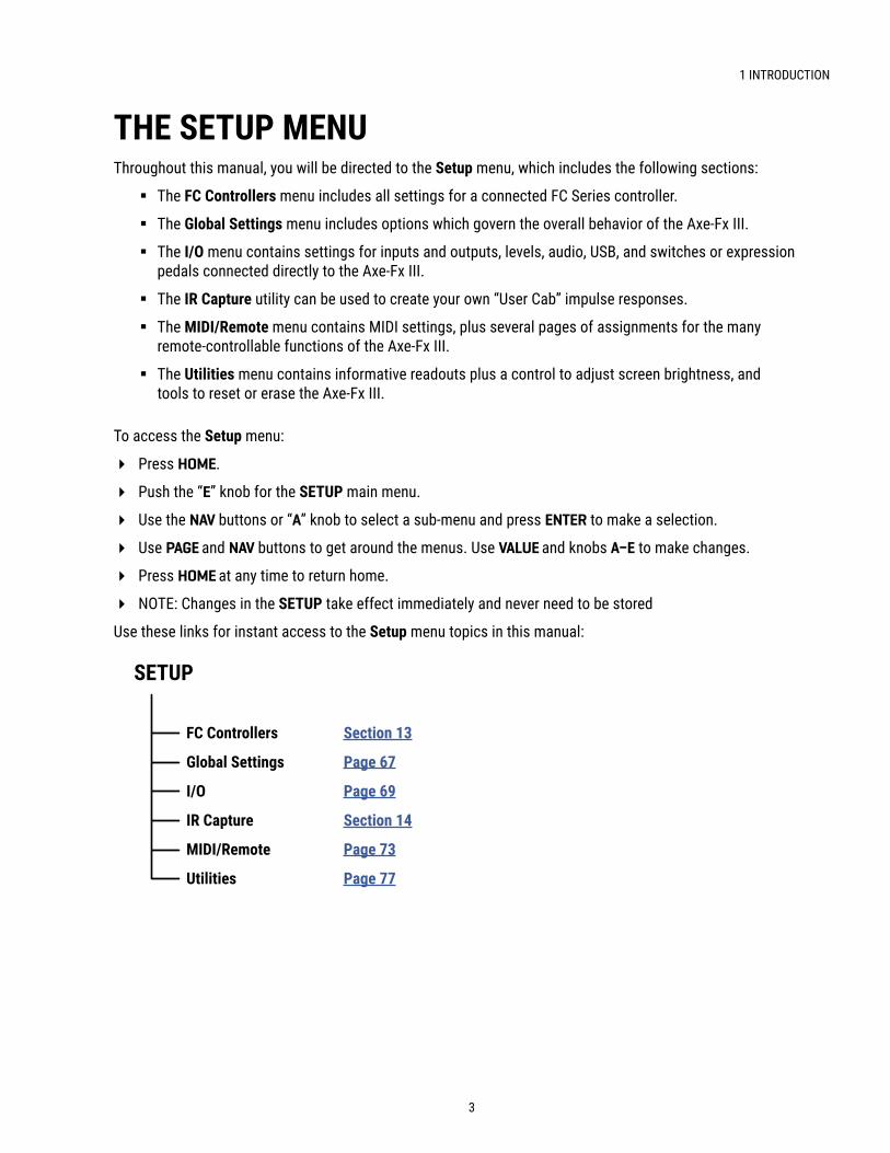
Throughout this manual, you will be directed to the Setup menu, which includes the following sections:
� The FC Controllers menu includes all settings for a connected FC Series controller.
� The Global Settings menu includes options which govern the overall behavior of the Axe-Fx III.
� The I/O menu contains settings for inputs and outputs, levels, audio, USB, and switches or expression pedals connected directly to the Axe-Fx III.
� The IR Capture utility can be used to create your own “User Cab” impulse responses.
� The MIDI/Remote menu contains MIDI settings, plus several pages of assignments for the many remote-controllable functions of the Axe-Fx III.
� The Utilities menu contains informative readouts plus a control to adjust screen brightness, and tools to reset or erase the Axe-Fx III.
To access the Setup menu:
� Press HOME.
� Push the “E” knob for the SETUP main menu.
� Use the NAV buttons or “A” knob to select a sub-menu and press ENTER to make a selection.
� Use PAGE and NAV buttons to get around the menus. Use VALUE and knobs A–E to make changes.
� Press HOME at any time to return home.
� NOTE: Changes in the SETUP take effect immediately and never need to be stored
Use these links for instant access to the Setup menu topics in this manual:
THE SETUP MENU
SETUP
FC Controllers Section 13
Global Settings Page 67
I/O Page 69
IR Capture Section 14
MIDI/Remote Page 73
Utilities Page 77

4
1 INTRODUCTION
INPUT1
OUTPUT1
UseOut 1 L
for Mono
FRFR speakers, Studio MonitorsAudio Interface or Mixer
AddOut 1 R
for Stereo
The most popular and flexible way to enjoy the Axe-Fx III is through a full-range system such as studio monitors, a high-quality PA, or full-range cabinets designed specifically for guitar. All of the factory presets are designed for this type of setup.
Of course you can use the unit in many other types of setups, including those which integrate with tube amps, USB recording, guitar speakers, 3rd-party outboard equipment, and more. You can find over ten examples in Section 4 of this manual.
Basic setup instructions for a typical direct/full-range rig appear below:
FAQ: WHY FULL RANGE?
A Full-Range Flat Response (“FRFR”) system aims to reproduce the entire audio spectrum without any tonal coloration. In comparison, most traditional guitar speakers are sonically limited, with tonal coloration and limited low and high response. Each speaker cabinet has its own effect on your sound, and a 1×12 open-back combo is never going to sound like a 4×12 stack. In comparison, full-range flat-response studio monitors, PA speakers, and FRFR speakers designed specifically for guitar are designed to reproduce anything you play through them. The output of a fully modeled signal path is in fact closer to what you’d hear in a finished mix or recording, so it sounds best when played through a system that is designed for full range. Of course, many other setup types exist, as demonstrated in the many examples shown in Section 4 of this manual.
q Begin with all level knobs turned down. Connect your guitar to the front or rear Instrument input (Input 1).
The Axe-Fx III is also perfect for bass and other instruments.
w Connect Output 1 to your mixer, studio monitors, audio interface, PA system, full-range speakers, power amp inputs, etc.
• For a mono rig, use Out 1 Left.
• For stereo, also connect Out 1 Right.
• Use XLR outputs to connect to balanced inputs, or use the 1/4" outputs when connecting to unbalanced inputs.
• Use Humbuster cables with 1/4" outputs to reduce hum from ground loops.
e Turn up the front panel OUT 1 knob and adjust the level on your monitors as desired.
Explore factory presets by turning the VALUE wheel.
Select Scenes within a preset by using NAV Up/Down.
QUICK CONNECT GUIDE

5
1 INTRODUCTION
Setting proper levels is critical but easy, with many meters to help you while you work.
INPUT LEVELSThe Axe-Fx III comes ready-to-use for the typical guitar or bass, but you should check that your guitar is not clipping the inputs.
Connect a guitar to the Instrument input. Choose your loudest pickup setting and set all the guitar controls to “wide open.” Play loudly to push the levels as you watch the front panel INPUT 1 meter LEDs. A red LED on the input meter indicates a level of -6dB, which is still safely below clipping. Adjust the input trim so your loudest playing “tickles the red.” It is of course also fine if a lower output guitar never hits the red. In general, you should set input levels as high as possible without clipping:
� Open SETUP : I/O : Input page. � Adjust Input 1/Instrument input levels using the A knob.
Inputs 2, 3 and 4 can be adjusted using the same method. Each has its own Input trim parameter on the Input page of the I/O menu under SETUP.
You can also monitor levels on the Meters page of the Home menu.
Except at the very lowest settings, Input level adjustments do not affect gain levels. As you adjust the input level to the A/D converter, the output is compensated accordingly, so what you hear is not affected by how you set these controls.
SETTING LEVELS
OUTPUT LEVELSOutput levels are very easy to monitor on the front panel meters, and easy to control using the four front panel LEVEL knobs. You can also monitor output levels in higher resolution by paging to the Meters page from the Home menu.
Outputs 1-2 are ready to be connected to consumer line inputs (-10 dbV). If you are connecting to professional-grade equipment operating at +4dBu, set the nominal output levels as follows:
� Page to SETUP : I/O : Audio.
� Adjust Output 1: Output Level or Output 2: Output Level to +4dBu.
Learn more about the I/O Menu on p. 69.
If you notice the Outputs clipping, this means your presets are too hot. Section 7 on p. 49 is dedicated to the important subject of adjusting preset levels.
The Meters page of the Home menu shows all I/O levels.
The Layout also has a Meters view showing block levels.

6
1 INTRODUCTION
HUMBUSTER™ CABLESMost FRFR setups use the XLR outputs of the Axe-Fx III into the balanced inputs of mixers, monitors, and other devices. For these applications, XLR cables or XLR-to-TRS cables are typical.
When connecting the 1/4” outputs of the Axe-Fx III to unbalanced 1/4" inputs on other devices, you can use standard 1/4" patch cables, but there is a better option. Humbuster™ technology on all 1/4" outputs of the Axe-Fx III can significantly reduce unwanted noise due to the common problem of a ground loop. For this to work, you must use a special Humbuster cable. This has one TRS end (like a balanced cable) and one TS end (like a guitar cable). The TRS end connects to the Axe-Fx III. The TS end connects to your other device or amp.
Humbuster cables are available from http:/www.fractalaudio.com/cables. You can make your own by following the diagram below. Be sure to use high-quality connectors and shielded cable.
The Axe-Fx III comes pre-configured for stereo but you can connect it in mono with no issues. In mono, however, you may find that certain presets or settings produce unexpected results. For example, a panner sounds like a tremolo when one channel is missing. A ping-pong delay may “ping” but never “pong”. Stereo enhancers or certain types of modulation may not be apparent at all. Even the tone can change if amps or cabs have been panned. Here is an overview of several scenarios, with recommended settings for each.
MONO VS . STEREO
� STEREO: No special settings required.
� HALF STEREO: Leaving the Axe-Fx III in its default stereo configuration but connecting only one (Left) output results in “half-stereo.” This setup works fine, aside from the exceptions mentioned above (ping-pong, panning, etc). No special settings required.
� MONO, COPY L>R: Sonically, this is identical to half-stereo, with the same limitations, except that mono signal is produced at both the left and right jacks so you can connect to two monitors. To switch to dual mono, open SETUP: I/O: Audio and set Mode for the desired output to “COPY L->R”.
� MONO, SUM L+R: In this setup, left and right channels are added together resulting in a mono signal at both left and right outputs of the Axe-Fx III. While this does not discard half of the channels like half-stereo does, summing has its own issues. For example, short delays or phase differences between channels can result in strange artifacts or cancellation. To switch to summed mono, open SETUP: I/O: Audio and set Mode for the desired output to “SUM L+R”.
On the Axe-Fx III, a flexible block-based I/O system makes it easy to use different outputs with different settings for different purposes. See Input and Output blocks in the “Blocks Guide”.
All options of the I/O menu under SETUP are detailed in Section 12.

7
1 INTRODUCTION
Once you have connected your Axe-Fx III you can begin to audition factory preset sounds. Remember that aside from a few templates, the factory presets are designed for use with full-range speakers, monitors, or headphones. See Section 4 for details on creating presets for other setups.
The Axe-Fx III contains 512 preset memories, each a fully independent rig with its own amps, cabs, effects, settings, controllers, and more. When you consider everything that is possible with Scenes and Channels, a single preset can easily cover an entire song, or even a whole show.
Here’s how to explore the factory presets:
� Press HOME to show the Home page, where you can switch presets.
� To change presets, turn the VALUE knob or use the NAV left/right buttons.
� Many factory presets contain extra Scenes. You can switch Scenes using NAV up/down or knob A. See p. 9 for an introduction to Scenes.
OTHER HOME MENU FUNCTIONS � The push functions of
the five knobs of the hme page provide access to other areas:
� Tuner (Page 65) � Layout grid (Page 8 and Page 34) � Controllers (Page 59) � FC Per Preset (See Section 13: FC Controllers). � Setup (Page 3 and Page 67).
� A mini-Tuner appears at the top of the Home page itself.
THE PRESETS DIRECTORY � You can also access a PRESETS directory:
� From the Home page, press PAGE RIGHT until the Presets page is shown. � Presets are shown in numerical order. To sort presets alphabetically by name, press the “Sort A–Z” button. � Use the VALUE wheel and NAV buttons to select any entry. � The ENTER key loads the selected preset and returns to the Home page
THE HOME PAGE: PRESETS
Previous Scene
Previous Preset
Next Preset
Next Scene

8
1 INTRODUCTION
In the world of traditional gear, our options are limited by budget, space, weight, and the limits of the gear itself. Building a rig means making hard choices. With the Axe-Fx III however, a limited selection of gear is instead replaced by a vast (ever-growing!) “inventory” of virtual amps, cabs, effects, and more. Every preset gives you the flexibility to design a totally new rig composed of whichever components you choose.
Let’s learn the vocabulary of preset creation. To create a preset, virtual pieces of gear are selected from the inventory and placed as blocks into the slots of the layout grid, a structure of rows and columns. Each block represents a different component like a wah pedal, amp, reverb, etc. Blocks are connected together using virtual cables, and you can create splits, merges or multiple parallel paths as needed. Passive shunts carry signal through empty grid spaces. Special input and output blocks connect to the various jacks and USB signals of the Axe-Fx III. The following graphic illustrates these concepts:
INTRO TO THE LAYOUT GRID
CABLECABLE
Let’s review what is happening above. Various blocks have been placed on the grid and connected with cables. Signal flow begins at the Input block on the left. It then goes to a Wah block. The wah connects to a shunt, which has no effect on the sound and is shown only to introduce the idea of how it carries signal from one location to another. The shunt is connected to an Amp block (we might set its type to “Plexi 100W High”), which in turn feeds a Cab (one of the many “4×12” options, perhaps). This is connected to a Reverb and then to an Output block. In this limited example, only a few blocks are shown on a partial grid. In reality the size of a preset is limited only by the grid structure, block inventory, and total processing power (“CPU”). You will find that you can create very large virtual rigs with multiple amps, cabs, and effects.
A new “ZOOM” feature shows the whole grid at once. Look for the ZOOM button on Layout menu pages.

9
1 INTRODUCTION
Imagine a rack system like those used by many guitar players over the past decades. In this system, various amps, pedals, and rack units are connected through a central switching system, which places components in or out of the signal path at will. Some componenets in a rig like this have their own settings that the switcher can control remotely—like the channels on an amp, or the different settings of a delay. Using the switcher, you set up different combinations gear and settings and then save a preset: Clean, Rhythm, Lead, etc. (Yes, this old rig does all this and weighs just a few hundred pounds!)
A single Axe-Fx III preset is comparable to an entire rig. Axe-Fx Scenes, are an innovation something like a switching system. A Scene stores whether each block is engaged or bypassed, and which of up to four “channels” it should be on. A Channel is like a preset within a block; each block has up to four channels, and every channel its own fully independent settings. For example, Channel A of a Drive block might be a “clean boost”, B could be a “screamer” , C a distortion, and D a fuzz. So, with channels, you get four different sounds from just one block! By switching blocks and channels for you, Scenes offer a way to select different sounds without changing presets.
Scenes offer many advantages. First, they eliminate “tap dancing” and make complex sound changes easy. Also, scene changes are fast and can even be perfectly seamless. Scenes are make it easy to set up delay and reverb for “spillover” so tails can ring out across changes. Scenes even have their own names, which is especially helpful as you step through them.
INTRO TO SCENES AND CHANNELS
IN 1 CMP 1A DRV 1
A AMP 1A CAB 1
A CHO 1A DLY 1
A OUT 1Here is our preset. The Input 1 block feeds a Compressor followed by a Drive, then into an Amp and Cab, followed by Chorus and a little Delay, ending up at the Output 1 block.
SCENE 1 – “Clean”: For scene 1, the Drive and Delay blocks are bypassed. We dial in the Compressor, Amp, Cab, and Chorus for a classic clean tone. Notice that the amp says “1A”. This means we are using Amp 1, set to channel A. Let’s imagine it as the “ODS-100 Clean” model. We name the scene “Clean”.
SCENE 2 – “Crunch”: To create scene 2, we bypass the Compressor, Chorus and Delay and engage the Drive. The Amp block is changed from channel A to channel B, which we dial in as a “Euro Blue” crunch model. Remember, each channel has a totally independent set of settings, so every amp parameter exactly as we wish for this scene: Drive, Treble, Mid, Bass, and many, many more. We then dial in Channel “A” of the drive block with a good “screamer” sound by selecting the “TS808 OD” type. Let’s name this scene “Crunch”.
SCENE 3 – “Lead”: Here’s our soaring lead. The Chorus is bypassed. We’ve changed the compressor to Channel “B” and dialed it in for sustain. The amp is the same as the “Crunch” scene but Drive changes to “B”, which we’ll make a “Fat Rat”. The Delay is on channel “B” dialed in with higher mix and feedback. We name the scene “Lead”.
Learn more in “Scenes & Channels” on p. 43
DRV 1A DLY 1
A
CMP 1A CHO 1
A DLY 1A
CHO 1A
SCENES AND CHANNELS: A VISUAL EXAMPLE
10
1 INTRODUCTION
GRID EDITING: QUICK STARTLearn more about working with the grid in Section 5. Meanwhile, here’s a very quick primer:
� From the Home page, press LAYOUT (knob B) or ENTER to show the “Edit” page of the Layout menu, commonly called the “grid”.
� Use the NAV buttons to move the cursor around the grid. � Turn the VALUE knob to cycle through the inventory of blocks at any grid location. When
you find the block you want, press ENTER to confirm. Press EXIT to cancel changes. � On the grid, “push” functions of the B, C, and D knobs allow you to toggle a block’s Bypass state,
Delete a block, or create/remove a connector Cable between any two blocks in adjacent columns. � To save any changes, press STORE, ENTER, ENTER.
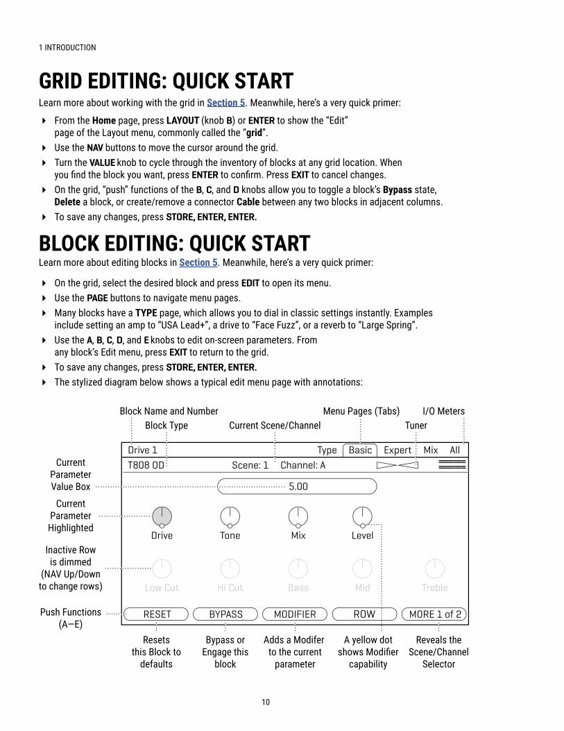
Block Name and Number Menu Pages (Tabs) I/O MetersBlock Type
CurrentParameterHighlighted
Inactive Rowis dimmed
(NAV Up/Downto change rows)
Push Functions(A—E)
CurrentParameterValue Box
TunerCurrent Scene/Channel
Resetsthis Block to
defaults
Bypass orEngage this
block
Adds a Modifer to the current
parameter
A yellow dotshows Modifier
capability
Reveals theScene/Channel
Selector
BLOCK EDITING: QUICK STARTLearn more about editing blocks in Section 5. Meanwhile, here’s a very quick primer:
� On the grid, select the desired block and press EDIT to open its menu. � Use the PAGE buttons to navigate menu pages. � Many blocks have a TYPE page, which allows you to dial in classic settings instantly. Examples
include setting an amp to “USA Lead+”, a drive to “Face Fuzz”, or a reverb to “Large Spring”. � Use the A, B, C, D, and E knobs to edit on-screen parameters. From
any block’s Edit menu, press EXIT to return to the grid. � To save any changes, press STORE, ENTER, ENTER. � The stylized diagram below shows a typical edit menu page with annotations:

11
1 INTRODUCTION
In addition to providing audio and MIDI capabilities, connecting the Axe-Fx III to a computer via USB allows you to use companion software applications Fractal-Bot and Axe-Edit III.
Fractal-Bot is a small, simple program used to update the Axe-Fx III when new firmware is released. It includes tools to backup or restore presets and other custom settings, and can be used to install downloaded presets or cabs.
Axe-Edit III is a full-featured software editor/librarian for the Axe-Fx III and FC Controllers. If you are comfortable with audio software or plug-ins, you will probably enjoy using this program to work with the Axe-Fx III. While the Axe-Fx III can certainly be operated from the unit’s front panel, Axe-Edit III brings a new level of convenience, including some “power-user” routines that aren’t possible on the unit itself (e.g. Block Library, Scene Swap, Performance Control pages, etc.). It also provides tools for managing presets and banks, installing Cab Packs, and more.
You can download Axe-Edit III for Mac or Windows at http://www.fractalaudio.com.
FRACTAL-BOT & AXE-EDIT III
USB OVERVIEWUSB provides the Axe-Fx III with a host of great features. A 16-core, 500 MHz microcontroller provides 16 channels of flawless 48kHz USB audio (8 in, 8 out) allowing the Axe-Fx III to be the center of your music workstation. The audiophile-grade signal path components and converters provide better audio performance than most dedicated USB audio interfaces. With 8×8 channels you can record multiple tracks of processed audio and DI signals, monitor backing tracks, audition stereo re-amps in real-time, and more. A USB audio sound source can even be placed on the grid for processing via the dedicated USB Input block.
USB is also required to use Axe-Edit and Fractal-Bot, the companion software products for the Axe-Fx III.
See Section 3: USB, on p. 19 for full details on the USB capabilities of the Axe-Fx III.

12
1 INTRODUCTION
Each of the two local Expression jacks of the Axe-Fx III allows you to connect one expression pedal or one external footswitch. A connected pedal or switch can change effect parameters, or operate any of a long list of global functions. Many factory presets are ready for use with one or more pedals.
TO CONNECT & CALIBRATE AN EXPRESSION PEDAL . . .Expression pedals for the Axe-Fx III should have a linear resistance taper and must have a maximum resistance in the range of 10–100kΩ. Expression pedals must be used with Tip-Ring-Sleeve (TRS) cables!
Connect your expression pedal to the desired jack with a TRS cable, then follow these instructions to calibrate:
� Page to the Pedal page of the I/O menu under SETUP.
� Ensure that Pedal Type is set to “CONTINUOUS”.
� Navigate to the Calibrate Pedal function and press the ENTER button.
� Follow the on-screen instructions to perform calibration.
TO CONNECT A SWITCH . . .Follow the instructions above and simply set Type to “MOMENTARY” or “LATCHING” based on what you’re connecting. (If you’re not sure, check with the switch manufacturer or try both settings to see which works better.) Calibration is not required. You can use a normal guitar cable (TS) for switches. Only ONE switch can be used at each pf the pedal jacks.
THE EV-SERIES EXPRESSION PEDALThe Fractal Audio Systems EV series of expression pedals are perfect for use with all Fractal Audio Systems products. The EV-1 is a full-sized expression pedal. The EV-2 is a compact version. These pedals feature rugged cast metal casings, a high quality 100kΩ potentiometer, and built-in analog volume pedal capability. Learn more at https://www.fractalaudio.com.
CONNECTING PEDALS DIRECTLY
WHAT IS TRS? “TRS” stands for TIP-RING-SLEEVE and describes the configuration of a 1/4" end plug or jack with three contacts. Normal guitar cables are “TS” (Tip-Sleeve) since they lack the “ring” used as a third contact. Expression pedals require TRS cables because voltage is transmitted to them on one contact (the tip), and returned on another (the ring), allowing the host device to sense pedal position. The third contact (sleeve) is connected to ground.
This section is for pedals connected to the local “Expression” jacks of the Axe-Fx III. For pedals connected to a MIDI or FC Series controller, see the next page.

13
1 INTRODUCTION
GLOBAL VOLUME PEDAL SETUPThe Axe-Fx III allows remote control of the volume at all inputs and outputs. If you have a second pedal, or if you want to use one pedal for global volume instead of expression, follow the instructions below:
The first step is to decide which volume you want to control. Adjusting Input volume affects gain/distortion and the behavior of level-dependent blocks like the compressor or gate. Adjusting Output volume does not affect level-dependent blocks, but scales everything you hear including effect tails. For all other volume options, you can insert a Volume block anywhere in your preset and control it with an “External Controller” as described above (See also “Modifiers” on p. 53.)
To set up a global volume pedal, first ensure that you have a pedal connected and ready to use. Then:
1. From the Home page, open SETUP: MIDI/Remote: Other.
2. NAV to the entry for the volume you want to control: Input 1, 2, 3, or 4, or Output 1, 2, 3, or 4.
3. Turn the “A“ or VALUE knob to assign a controller to your selected entry.
� Select “PEDAL 1 or PEDAL 2” for the onboard Expression jacks � Select “FC__ PEDAL __” for a pedal connected via an FC series controller. � Select a number if your pedal is transmitting a MIDI CC#. For example, by default, the Fractal Audio
Systems MFC-101 transmits CC#11 for XP1 and CC#16 for XP2.4. Test and EXIT when finished.
Learn about other options for global remote control in “The MIDI/Remote Menu” on p. 73.
GLOBAL EXPRESSION PEDAL SETUPPedals need to be assigned before they do anything. Once you have connected and calibrated a pedal according to the instructions on the previous page (or if you are using a MIDI or FC-connected pedal) you can globally assign it as “External 1”, which is used in many factory presets as a Wah controller.
To set “External 1” to respond to your connected pedal:
1. From the Home page, open SETUP: MIDI/Remote and change to the External page.
2. NAV to External Control 1.
3. Turn the “A” or VALUE knob to set this external controller to your pedal:
� Select “PEDAL 1” or “PEDAL 2” for the onboard Expression jacks. � Select “FC__ PEDAL __” for a pedal connected via an FC series controller. � Select a number if your pedal is transmitting a MIDI CC#. For example, by default, the Fractal Audio
Systems MFC-101 transmits CC#11 for XP1 and CC#16 for XP2.4. EXIT when finished. Most of the first 100 Factory Presets contain a Wah block you can test with.
Learn more about assigning pedals and switches to sound parameters in Section 9: Modifiers.

14
1 INTRODUCTION
This page is blank to preserve layouts when printing.

15
2 HARDWARE OVERVIEW
THE FRONT PANEL
q Chassis — The Axe-Fx III is housed in a rugged 3U steel chassis with a sleek anodized aluminum front panel. A pair of high-strength handles make the unit easy to manage.
wPower Switch — The front panel power switch turns the Axe-Fx III on or off with pop suppression.
eColor Display — A large 800×480 custom color display has 30x the resolution of previous models. The display has excellent brightness and contrast for high readability even in difficult conditions.
A, B, C, D, and E knobs — Five endless rotary push-encoders perform different functions on different menu pages. Most “Edit” menus show one or two rows of five knobs for easy 1:1 operation. On vertical menu pages, knob functions are indicated on-screen by labels (“A” through “E”). Push functions are shown on-screen as buttons.
HOME Button — This button shows the Home menu—a convenient starting point for loading or editing presets, and accessing the tuner, controllers, metering, and global setup options.
EDIT Button — This button opens the Edit menu for a block selected on the Layout grid. You can also tap EDIT sequentially to step through all blocks in the current preset (top-to-bottom, left-to-right). See “Presets” on p. 33 for more on editing presets.
STORE Button — Enters the Store menu where you can save presets and enter names for presets or scenes. See “Saving Changes” on p. 41.
TEMPO Button — Tap this button once to show the Tempo page of the Controllers menu, or tap 2+ times to set a new tempo. The tempo can also be entered using a footswitch or MIDI. After setting the tempo, press EXIT to go back to back to wherever you were. See “Tempo” on p. 63.
2 HARDWARE OVERVIEW

16
2 HARDWARE OVERVIEW
VALUE Knob — The VALUE knob performs different functions on different menu pages. In the Home menu, it selects presets. In Layout (grid) pages, it is used to add or modify blocks on the grid. In Edit menus, it changes parameter values, selects from lists, and more. A hidden “push” function enters the Layout (grid) of the current preset from other pages or menus.
aNAV Buttons — The four NAV buttons perform different functions on different menu pages. On the preset pages of the Home menu, they select and load Presets (Left/Right) and Scenes (Up/Down). In other menu pages, they select between on-screen parameters or options, moving the “focus” of the VALUE knob, as indicated by a blue highlight and brighter blue text.
sENTER and EXIT Buttons — The ENTER button executes commands, commits changes, accesses sub-menus, and more. EXIT works for cancel, escape, and various other functions.
dPAGE LEFT and PAGE RIGHT Buttons — These buttons step through menu pages, shown as “tabs” at the top of the display.
fMeter Bridge — Eight LED meters show the levels of every input and output on the Axe-Fx III. For inputs, the red LED lights at -6dB. Set input levels so your loudest playing “tickles the red” if possible (see p. 5). For outputs, the red LED indicates -1 dBFS and is therefore a more immediate indication of clipping. You can also find meters on the Meters pages of the Home and Layout menus.
gStatus LEDs — Three LEDs indicate important information. The Tempo LED flashes to show the current Tempo. The Edited LED lights whenever the current preset has been altered but not saved. The MIDI In LED lights while MIDI data is being received at the MIDI Input or via USB.
hOutput Level Knobs 1–4 — These knobs independently control the volumes at the corresponding rear panel outputs. The Output 1 knob simultaneously controls Output 1 XLR jacks and 1/4” jacks, and the headphones level. Outputs 3 and 4 are at unity gain when set fully clockwise.
jHeadphones Output — 1/4" Stereo Jack — Connect headphones here to monitor Output 1 (see above).
kFront Panel Instrument Input (mono) — (1) 1/4" Jack (unbalanced) — Plug your instrument into this jack intended specifically for use with electric, acoustic, and bass guitars. See Notes below for details about both front and rear instrument inputs.
NOTES ABOUT FRONT & REAR INSTRUMENT INPUTS
� The front Instrument input always overrides the rear instrument input. This allows you to build a rig using the rear input—with a wireless unit, for instance—and then change to the front input simply by plugging in a cable. There are no settings for this. The input switches automatically.
� Both front and rear Instrument inputs feature our “Secret Sauce IV” circuitry, which — among other things — lowers the noise floor using a proprietary technique and special analog input circuitry.
� The Input 1 block sets the impedance for Input 1 automatically, or can be manually overridden for “loading” effects on your pickups. See Input Blocks in the “Blocks Guide”.
� You can also connect guitars and other instruments to Inputs 2, 3 or 4. These are designated as LINE Level but accommodate high impedance sources so as not to load down guitar pickups.
� You can use traditional effect pedals in a loop, or between your guitar and the Axe-Fx III. You may need to trim the input when using a loud guitar or pedal. See “Setting Levels” on p. 5.

17
2 HARDWARE OVERVIEW
THE REAR PANEL
ANALOG INPUTSAxe-Fx III inputs are extremely flexible. Any input can be placed as a block on the grid for use in any number of scenarios. Example rig diagrams are provided in Section 4.
l Input 1 [Instrument] (mono) — (1) 1/4" Jack (unbalanced) — Plug your instrument into this jack intended specifically for use with electric, acoustic, and bass guitars. See Notes (previous page) for details.
; Input 2 L+R (stereo) — (2) XLR/1/4" Combo Jacks (balanced) — These combo jacks combine XLR female and 1/4" jacks in one, accepting either balanced or unbalanced line level signals.
2) Input 3 L+R (stereo) — (2) 1/4" Jacks (balanced) — Input balanced or unbalanced line level signals.
2! Input 4 L+R (stereo) — (2) 1/4" Jacks (balanced) — Input balanced or unbalanced line level signals.
Balanced audio connections are resistant to noise and interference. It is best to use XLR or TRS (3-conductor) cables when connecting Axe-Fx III inputs 2, 3 and 4 to the balanced outputs of other devices. Regular TS-type “patch” cables (2-conductor) are sufficient when connecting to unbalanced outputs.
ANALOG OUTPUTSLike inputs, outputs are typically used by placing blocks on the grid, though in this case the various XLR and 1/4" Humbuster jacks suggest different uses for different outputs. Example rig diagrams are provided in Section 4.
Humbuster technology on all 1/4" outputs can significantly reduce hum from ground loops. Humbuster Cables are available at http://shop.fractalaudio.com. Learn more on p. 6.
2@ Output 1 L+R (stereo) — (2) XLR-Male (balanced) and (2) 1/4" Jacks (Humbuster) Use the XLR jacks to connect Output 1 to balanced inputs, employing the provided ground lift switch if necessary to reduce 60-cycle hum. Use the 1/4" unbalanced Humbuster outputs to connect to unbalanced inputs, such as those on guitar power amps and other devices. Output 1 is utilized as the main output in all factory presets.

18
2 HARDWARE OVERVIEW
2# Output 2 L+R (Stereo) — (2) XLR-Male Jacks (balanced) — Use these XLR jacks to connect to balanced inputs. Use the ground lift switch if necessary to reduce unwanted 60-cycle hum.
2$ Output 3 L+R – (Stereo) — (2) 1/4" Jacks (Humbuster) — Use these 1/4" unbalanced outputs to connect to unbalanced inputs, such as those on guitar power amps or other devices.
2% Output 4 L+R – (Stereo) — (2) 1/4" Jacks (Humbuster) — Use these 1/4" unbalanced outputs to connect to unbalanced inputs, such as those on some guitar power amps or other devices.
Outputs 3 and 4 are designed for unity gain applications such as the popular “Four-Cable Method” and other setups using traditional guitar amps. Set the OUT 3 and OUT 4 Level knobs fully clockwise for unity gain. See the relevant rig diagrams in Section 4 for more information.
2^Digital Inputs and Outputs — This includes both S/PDIF and AES/EBU format input and output jacks. Only one or the other pair can be active at any time depending on the setting of the SPDIF/AES Select parameter found in SETUP: I/O: Audio. These jacks transmit and receive at a fixed rate of 48k. The Axe-Fx III defaults to using its internal clock but can also use Word Clock signals received at the digital input. Find descriptions of related parameters under “I/O: AUDIO Page” on p. 70.
2& Expression Inputs — (2) 1/4" Jack — These are used to connect an external expression pedal or switch to control various functions of the Axe-Fx III. See “Connecting Pedals Directly” on p. 12 for more information.
2*FASLINK II Connector — Connect Fractal Audio FC-6 or FC-12 foot controllers here. A standard XLR cable powers the FC without an external “wall wart” adapter, and carries 2-way communications.
NOTE: The FASLINK II port on the Axe-Fx III is designed for our “FC” series of foot controllers and is NOT compatible with the FASLINK port on our MFC-101 MIDI foot controller.
2( USB — This provides the Axe-Fx III with 8×8 USB audio and 2-way MIDI capabilities when connected to a compatible Mac or PC. Drivers are required for Windows. No driver is required for Mac OS X. See Section 3: USB, on p. 19 for more.
3) MIDI Ports — The MIDI IN port of the Axe-Fx III allows you to use a 3rd party MIDI controller or interface to control various functions including preset and scene selection, effect bypass, channel changes, parameter changes, and more. Messages received at the MIDI IN port are passed automatically to the MIDI THRU port. The MIDI OUT port transmits MIDI data generated by the Axe-Fx III to connected devices.
See “The MIDI/Remote Menu” on p. 73 for details on how to configure the MIDI Channel and other options. MIDI messages can also be transmitted by presets or by the Scene MIDI block. See
3!AC Power Receptacle — Insert the supplied power cable and connect the other end to a grounded AC power receptacle. The Axe-Fx III has a universal power supply, which means it can be used around the world without an adapter simply by changing the cable.

19
3 USB
COMPUTER INTEGRATION
3 USB
With a USB connection to a computer, the Axe-Fx III functions as an 8-in/8-out 24-bits 48kHz ultra-low latency audio interface for Mac and Windows computers. A driver is required for use under Windows. This extremely high-quality audio interface is powerful enough to be the centerpiece of a Digital Audio Workstation (DAW).
In addition, a computer connection provides high-speed “MIDI-over-USB” for remote control of the Axe-Fx III, backups, updates, editing, and more.
WINDOWS MINIMUM REQUIREMENTSOS: Windows 7 SP1 or newer (all versions compatible with x86 or x64).
CPU: Intel Core 2 @1.6 GHz or better, or AMD equivalent.
Memory: 1GB minimum.
USB: USB 2.0 support required.
Driver: The Axe-Fx III is fully class-compliant, but driver installation is still required for use under Windows.
The Windows driver can be downloaded at http://www.fractalaudio.com/support.
Step-by-step instructions are included with the installer.
MAC MINIMUM REQUIREMENTSOS: OS X 10.6.8 for MIDI-over-USB (Fractal-Bot, Axe-Edit III, Cab-Lab, etc.).
OS X 10.9 or later required for USB audio. An issue in older OS X versions causes audio pops.
CPU: Intel Processor.
Memory: 512MB minimum.
USB: USB 2.0 support required.
Driver: No driver is required for Mac OS. The Axe-Fx III is class-compliant.
Important: If you are using a USB-C to USB adapter on an Apple computer, always plug the USB-C end of the adapter into a USB-C or Thunderbolt 3 (USB-C) port on your Mac first, and then connect the USB cable of your Axe-Fx III to the adapter.
MIDI-OVER-USBThe USB connection also carries high-speed “MIDI-over-USB”. On the computer, the Axe-Fx III MIDI In port inputs MIDI data from the Axe-Fx III. The Axe-Fx III MIDI Out port transmits data from the computer to the Axe-Fx III.
MIDI-over-USB performs the same functions as regular 5-pin MIDI, only faster. For example, the Axe-Fx III will process an incoming MIDI Program Change message whether that message is transmitted through the unit’s own MIDI IN port, or via the Axe-Fx III MIDI Out port of a connected computer.

20
3 USB
COMPUTER INPUTS 1+2Source: The output of the OUT 1 block on the grid. Applications: Record the stereo processed output of the Axe-Fx III.
COMPUTER INPUTS 3+4Source: The output of the OUT 2 block on the grid. Applications: Record a second stereo processed signal.
Each of the 16 USB audio channels is “hard-wired” to a specific Axe-Fx III input or output. As with all USB Audio devices, inputs and outputs are defined with respect to the computer.
COMPUTER OUTPUTS 1+2Destination: The Output 1 D/A converter which feeds all Output 1 jacks, Headphones, and possibly SPDIF/AES. USB audio is added to the signal from the OUT 1 grid block (if any) and this mix is passed to the output converters. Applications: Play stereo audio from the computer through the Axe-Fx III.
COMPUTER OUTPUTS 3+4Destination: The Output 2 D/A converter which feeds the Output 2 jacks, and possibly SPDIF/AES. Applications: Play a second stereo signal through the Axe-Fx III. Ideal for backing tracks so they can be fully independent from processed guitar at Output 1.
COMPUTER OUTPUTS 5+6Destination: The input of the IN 1 block IF Input 1 Source is set to “USB”. See “Input 1 Source” on p. 70 and Input Blocks in the Blocks Guide Xx. Applications: Route tracks to the Axe-Fx III for processing. Ideal for re-amping a DI.
COMPUTER OUTPUTS 7+8Destination: The IN U (USB) grid block. Signal appearing here will be processed by the block’s noise gate, etc. Applications: Route additional DAW track(s) to the Axe-Fx III for processing without requiring changes to SETUP: I/O: Audio.
USB INPUTS AND OUTPUTS
INPUT 2, 3 or 4
OUTPUT 1
OUTPUT 2
IN 1/INSTR
grid block
grid block
grid block
grid block
COMPUTER INPUTS 5+6Source: The signal at the Input 1/Instrument jack (front or rear). Note: Input 1 is mono, so the same signal is fed to both Left and Right channels. Applications: Record a DI signal for re-amping.
COMPUTER INPUTS 7+8Source: The signal at your choice of input jacks, 2, 3 or 4. (Left = 7, Right= 8) Make this selection in SETUP : I/O : Audio (Default Input 2) Applications: Record a stereo source without processing.
Note: The above two pairs can be swapped, so that INs 1+2 go to Out 2 and INs 3+4 go to Out 1. Find the option USB OUTPUT MAPPING under SETUP : I/O : Audio .

21
3 USB
By default, Mac OS X system audio plays through USB Channels 1+2 of a connected device. If you are using a multi-channel audio application such as Logic or Mainstage, you can simply select the desired outputs on a track-by-track basis. This section applies only to system audio.
Audio from apps such as Apple Music or iTunes will normally be mixed in at output 1, which is also the destination for processed guitar signals in all factory presets.
If you want backing tracks and guitar signals to appear at different output jacks, you might think at first that you need to change every factory preset to use a different output for your guitar, but there are two other options.
The first option, covered in a note on the previous page it to remap USB Audio playback 1+2 to go to Out 2 L+R instead of Out 1 L+R. Find this option USB OUTPUT MAPPING under SETUP : I/O : Audio.
The second option is to use the “Configure Speakers” option in Mac OS. To change this setting:
1 . First ensure that the Axe-Fx III is selected as your output device.
� Connect the Axe-Fx III to your Mac as described on p. 19. � Open the Output pane of Sound preferences (Choose Apple menu > System Preferences, click Sound,
then click Output) and select the Axe-Fx III .2 . Open Audio MIDI Setup (find it in Utilities, inside your computer’s Applications folder).
3 . Select the Axe-Fx III device from the list, then click Configure Speakers.
4 . Make sure that the Configuration is set to “Stereo” and then select the desired left and right channels.
5 . Click Done to finish.
MAC OS X SYSTEM AUDIO

22
3 USB
USB RE-AMPINGThe Axe-Fx III USB Audio capabilities are perfect for “re-amping”, a method in which the raw un-processed DI output of a guitar is recorded and then re-processed later through the amp, cab, and effects of your choice. Re-amping has many benefits. First, it allows you to record when inspiration strikes, capturing a DI instead of obsessing over final tone. Later, you – or a mixing engineer – can redesign a sound as your track’s production advances. Also, punches and edits made on the DI track are essentially made inaudible by the re-amping process. In comparison to other products, the Axe-Fx III allows you to use the unit in the best and most effective re-amping workflows, including being able to dial in new tones while simultaneously listening to the track for context.NOTE: This method is for USB Re-Amping. For analog reamping, simply copy Input 1 to Output 3 or 4 (p. 71).This tutorial also assumes you are using default settings for the varioys parameters in Setup: I/O.
STEP 1: RECORDINGThe following tutorial assumes that the Axe-Fx III has been selected as the audio interface in your Digital Audio Workstation (DAW), and that you have connected Output 1 L/R to studio monitors, or that you are monitoring through the Axe-Fx III headphones jack. The details for each step below may vary slightly from one DAW to another, but this guide should be easy to adapt to your own environment.
1 . In your DAW, select Axe-Fx III as the main audio interface. Set the main outputs to Axe-Fx III Outputs 1+2. 2 . Create a new project in the DAW, and set its sample rate to 48kHz. Record or insert any backing tracks.3 . Connect your guitar to the Instrument input and select a preset well-suited to the material you’re recording.4 . For this tutorial, we will record both the processed output and the DI.
� Create a mono track. Name this track something like “Guitar DI”. Set its input to Input 5. This is the DI output of the Axe-Fx III. This will record the signal at the Input 1 Instrument jack with no processing.
� Create a stereo track. Name this track something like “Guitar Reference 1”. Set its inputs to Axe-Fx III Inputs 1+2. This will record the processed guitar signal sent on the grid to the OUT 1 block.
5 . Arm both of your guitar tracks for recording, making sure that Software/Input Monitoring is NOT enabled.6 . Hit RECORD and roll the track. You should see signal on both tracks. Be aware: while the processed track will
show “hot” levels, the signal level on a DI track will appear to be very low. This is NORMAL! You are recording the instrument level signal exactly as it comes out of your guitar with no pre-amplfication.
STEP 2: RE-AMPINGFor basic re-amping, we will temporarily change one setting on the Axe-Fx III. Press HOME and open SETUP. Navigate to the I/O menu, and change Input 1 Source to “USB (CHANNELS 5/6)”. Remember to change this back when you finish re-amping.
1 . MUTE the “Guitar Reference 1” track. 2 . Change the output of your “DI” track to Axe-Fx III Output 5/6 .3 . To demonstrate that re-amping is working, choose a totally different preset on your Axe-Fx III. Solo your DI
track, then rewind and hit PLAY. You should hear the DI being processed by your new Axe-Fx III preset.4 . Record the re-amp. Create a stereo track. Name this track something like “Guitar Re-Amp 1”. Set its inputs to
Axe-Fx III Inputs 1+2. 5 . Arm your re-amping track for recording, making sure that Software/Input Monitoring is NOT enabled.6 . Rewind, hit RECORD, and roll the track. The output of the preset is recorded.
Again, the method described here is basic, but it should serve as a guide to get you started. Review the previous page to inspire other workflow ideas.

23
4 SETTING UP
This section provides an overview of various ways to use the Axe-Fx III. These diagrams represent just a few of the many ways to use this flexible product, and even if you only intend to use a basic setup you can still learn from looking over this section.
4 SETTING UP
GENERAL PRINCIPLESPOWER & LEVELS
� When creating a new setup, begin with all level knobs turned down and all devices powered off. � The Axe-Fx III features pop suppression on startup, but speakers or
monitors should still be powered on last whenever possible. � Basic surge/spike protection is recommended but ot required.
AXE-FX III INPUTS � When connecting a guitar to the Axe-Fx III, the front or rear Input 1/Instrument jacks are preferable.
These feature “Secret Sauce IV” circuitry, which lowers the noise floor using a proprietary technique and special analog input circuitry. The front jack overrides the rear one, so you can connect in different ways without changing menu settings even when the rear jack is utilized in a rack system.
� You can also connect guitars and other instruments to Inputs 2, 3 or 4. These are designated as LINE level but accommodate high impedance sources so as not to load down guitar pickups.
� When connecting the outputs of other devices to inputs on the Axe-Fx III, use appropriate cables and connectors. For balanced signals use balanced connectors. Regular guitar cables are fine for unbalanced connections to the inputs of the Axe-Fx III.
� Setting Input Levels correctly is important. See “Setting Levels” on p. 5.
AXE-FX III OUTPUTS � Outputs 1 and 2 default to -10 dBV. You may wish to change these to +4 dBu when connecting
to to professional audio equipment. Find these settings on under SETUP: I/O: Audio � When connecting to a device with balanced inputs, it is best to use the XLR
outputs of the Axe-Fx III with XLR cables or XLR-to-TRS cables. � If a connected device has unbalanced inputs, use the unbalanced 1/4" outputs of the Axe-Fx III. Humbuster
cables are not required, but can help prevent the noise associated with ground loops. Purchase Humbuster cables at shop.fractalaudio.com or from your nearest Fractal Audio Systems dealer. (See p. 6.)
MONO/STEREO � Any setup can easily be adapted for mono or stereo with some simple changes to input and output settings. � See “Mono vs. Stereo” on p. 6 for an introduction, and “I/O: AUDIO
Page” on p. 70 for details on I/O parameters.
USING THE AMP BLOCK WITH TRADITIONAL GUITAR SPEAKERS � When using the Axe-Fx III amp block into traditional (not FRFR) guitar speakers, certain advanced
parameters warrant special consideration. On the “Speaker” page of the Amp block, set Speaker Drive to zero. You may also wish to zero Speaker Compression. Also consider matching LF Resonance Frequency to match the resonance of your connected cab — if you know it.

24
4 SETTING UP
CONNECTIONS � Connect your guitar to
Input 1 (Instrument) .
� Connect Output 1 to the input of your FRFR System.
� The presets used for this setup also work great with headphones.
FRFR/DIRECTGlobal Settings: Default Presets: Factory or Custom
This is by far the most popular type of setup, taking full advantage of the ability of the Axe-Fx III to every part of an “end-to-end” guitar chain, from stompboxes to amps, cabs, post effects, and more, for maximum versatility.
Output 1 is connected directly into full-range, flat response (“FRFR”) speakers such as those offered especially for guitar players by a number of manufacturers. Such systems are typically self-amplified (“active” or “powered”), but may consist of separate “passive” full-range speakers and a full-range power amp. Other suitable FRFR systems include high-quality PA speakers (including “Personal Monitor” wedges) or studio monitors.
In some cases, signal from the Axe-Fx III may pass through a mixer first. That’s fine, as long as you connect to LINE inputs. You do NOT need to use a mic preamp! Contact your mixer’s manufacturer if you have any questions.
All Global and I/O settings are at default values. All Axe-Fx III factory presets are designed for this setup.
Adjust overall levels using the front panel OUT 1 knob.
This is also the setup for a Digital Audio Workstation (DAW). Just add a computer connected via USB (don’t forget drivers if you’re running Windows) and the speakers connected to your Axe-Fx III become the main monitors for the DAW. Headphones can also be used.
INSTRIN
PERSONALFRFR
MONITORS
OUTPUT1L
OUTPUT1R
LINEINPUT
LINEINPUT
Optional for Stereo
Frontor Rear

25
4 SETTING UP
CONNECTIONS � Connect your guitar to
Input 1 (Instrument) .
� Connect Output 1 to the input of your FRFR System.
� In SETUP: I/O: Audio, set Output 2 Copy Output 1 to “ON” .
� Connect Output 2 to the front-of house system.
� This will presumably be a balanced connection, so use XLR cables if so.
� If you are working with a sound technician, be sure to tell them that you are outputting a hot LINE level input — NOT a microphone level signal. They should use a balanced line input without a preamp.
� Also tell them you are sending a fully processed “mix-ready” sound, and that — at least to start — they should initialize the channel with no EQ or processing.
FRFR MONITOR + FRFR TO FRONT-OF-HOUSEGlobal Settings: “Out 2 Copy Out 1” Turned ON Presets: Factory or Custom
This type of setup is similar to the previous FRFR/Direct setup except that it also sends signal to a mixer for front- of-house mixing (and possible band monitors). In this configuration, the Axe-Fx III creates a fully modeled end-to-end guitar signal path for the ultimate in tonal flexibility—stompboxes, amps, cabs, post effects, and more.
Output 1 is connected directly to your own monitors. Use full-range flat response (“FRFR”) monitor speakers such as those offered especially for guitar players by a number of manufacturers. These might be self-powered or passive, with an external power amp. High-end PA monitor wedges can also be fantastic for this purpose.
Output 2 is used as an independent copy of Output 1. For this example, this is accomplished with a Global settings change rather than inserting an Output 2 block in every preset. (See “Connections” below for details.)
In the event that your monitors are stereo but front-of-house wants mono, consider whether you want to send them half-stereo or summed stereo and change SETUP: I/O: OUTPUT 2 Mode (see “Mono vs. Stereo” on p. 6).
Adjust you own monitor level using the front panel OUT 1 knob.
Adjust your send level to front-of-house using the front panel OUT 2 knob. One advantage of this setup is that you can adjust stage levels and house levels independently.
INSTRIN
PERSONALFRFR MONITOR
FRONT-OF-HOUSEMIXER/PA
OUTPUT1L
OUTPUT2L
OUTPUT2R
OUTPUT1R
LINEINPUT
LINEINPUT
Optional for Stereo
Frontor Rear
Optionalfor Stereo
26
4 SETTING UP
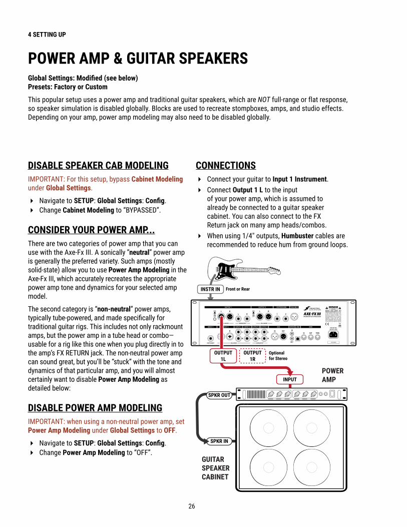
POWER AMP & GUITAR SPEAKERSGlobal Settings: Modified (see below) Presets: Factory or Custom
This popular setup uses a power amp and traditional guitar speakers, which are NOT full-range or flat response, so speaker simulation is disabled globally. Blocks are used to recreate stompboxes, amps, and studio effects. Depending on your amp, power amp modeling may also need to be disabled globally.
DISABLE SPEAKER CAB MODELINGIMPORTANT: For this setup, bypass Cabinet Modeling under Global Settings.
� Navigate to SETUP: Global Settings: Config. � Change Cabinet Modeling to “BYPASSED”.
CONSIDER YOUR POWER AMP . . .There are two categories of power amp that you can use with the Axe-Fx III. A sonically “neutral” power amp is generally the preferred variety. Such amps (mostly solid-state) allow you to use Power Amp Modeling in the Axe-Fx III, which accurately recreates the appropriate power amp tone and dynamics for your selected amp model.
The second category is “non-neutral” power amps, typically tube-powered, and made specifically for traditional guitar rigs. This includes not only rackmount amps, but the power amp in a tube head or combo—usable for a rig like this one when you plug directly in to the amp’s FX RETURN jack. The non-neutral power amp can sound great, but you’ll be “stuck” with the tone and dynamics of that particular amp, and you will almost certainly want to disable Power Amp Modeling as detailed below:
DISABLE POWER AMP MODELINGIMPORTANT: when using a non-neutral power amp, set Power Amp Modeling under Global Settings to OFF.
� Navigate to SETUP: Global Settings: Config. � Change Power Amp Modeling to “OFF”.
CONNECTIONS � Connect your guitar to Input 1 Instrument. � Connect Output 1 L to the input
of your power amp, which is assumed to already be connected to a guitar speaker cabinet. You can also connect to the FX Return jack on many amp heads/combos.
� When using 1/4" outputs, Humbuster cables are recommended to reduce hum from ground loops.
POWER AMP
GUITARSPEAKERCABINET
INSTR IN
OUTPUT1R
Optional for Stereo
Front or Rear
INPUT
OUTPUT1L
SPKR OUT
SPKR IN

27
4 SETTING UP
POWER AMP & CAB + FRFR/DIRECT Global Settings: Default, check I/O Mono/Stereo settings Presets: Custom
In this setup, custom presets simultaneously send two different signals—WITH speaker sims sent to a full-range front-of-house/monitors P.A. mix, and one WITHOUT speaker sims, sent to a “backline” rig consisting of a power amp and traditional guitar cab. For this example, we are assuming that the backline system uses a neutral power amp.
Output 1 connects to a full-range system—typically the house PA—sending a complete virtual rig tone, including simulated speakers. This provides all the benefits of going direct: versatile, consistent tone without “bleed” at very controllable volume levels for a better overall mix.
Output 2 sends a separate signal, almost identical to the first, but without speaker simulation—because it will be going to a power amp and traditional guitar speaker. This approach provides a very familiar “backline” experience—great natural sustain and feedback, “moving air,” and familiar stage volume and presence.
CONNECTIONS � Connect your guitar to Input 1 (Instrument).
� Connect Output 1 to the Front-of-House PA. Inform the sound technician that the Axe-Fx III outputs a direct LINE level signal which should initially not require any EQ or settings typically used on a mic’d guitar cabinet.
� Connect Output 2 to the input of your power amp. Again, we are assuming a neutral power amp is in use (see note, p. 26).
� If using the 1/4" outputs, Humbuster cables are recommended to reduce hum from ground loops.
Be sure to avoid using a microphonepreamp or channel settings that might undesirably color the sound.
FRONT-OF-HOUSEMIXER/PA
Frontor Rear
OUTPUT1L
LINEINPUT
OUTPUT1R
Optional for Stereo
OUTPUT2R
Optionalfor Stereo
INSTRIN
OUTPUT2L
SPKRIN
SPKROUT
GUITARSPEAKERCABINET
GUITARSPEAKERCABINET
POWERAMP
INPUT
IN1 WAH DRV AMP CHO DLY REV CAB OUT1
OUT2
This setup requires custom presets with both Output 1 and Output 2 blocks on the grid. Output 1 is at the end of the chain (where it appears in factory presets) and Output 2 taps the signal just before the cab block as shown below.
Note that the cab block has been moved to after the effects, which may collapse them to mono at Output 1. If a stereo signal is required at Output 1, the cab block must be modified for stereo use. Another solution would be to split the signal after the amp into separate chains of [Cab—Effects—Out 1] and [No-Cab—Duplicate Effects—Out 2].

28
4 SETTING UP
Global Settings: Default, but see “Tip” Below Presets: Custom
The Four-Cable Method (“4CM”) setup places the Axe-Fx III in two places at once with two separate processing chains. The first goes in front of your amp, where a chain of “pre” effects like wah and drive replace traditional stompboxes. The second placement is in the effects loop of the same amp, where a chain of “post” effects like delay and reverb appear. Although a head and separate cab are shown, many combo amps also offer an onboard effects loop and can be used as well.
4CM requires special presets with no Amp or Cab blocks. A stylized illustration appears below. Signal hits the Axe-Fx III first, where it is processed by pre effects. Output 3 feeds the front of the amplifier. A chain of post effects is run in the amp’s FX loop using Input 4 and Output 4. Note that the pre and post chains are not connected to each other at all on the grid. In fact, either chain can be as simple or as complex as desired.
FOUR-CABLE METHOD (“4CM”)
INSTR IN
GuitarAmp
INPUT4L
FX SEND
FXRETURN
Amplifier
Model 50
OUTPUT4L
OUTPUT4R
OUTPUT3L
MAININPUT
Optionalfor Stereo.
Front or Rear
Pre-FX Post-FX
IN1 WAH DRV OUT3 IN 4 DLY REV OUT4etc. etc.
CONNECTIONS � 4CM requires custom presets with no Amp or Cab
blocks (see above). A template is included (#382).
� Connect your guitar to Input 1 (Instrument) .
� Connect Output 3 L to the input of your amp. Set the front panel OUT 3 knob fully clockwise for unity gain operation. A Humbuster cable is recommended to reduce hum from ground loops.
� Connect your amp’s FX Send to Input 4 L on the Axe-Fx III. Input levels can be adjusted on the Input page of the I/O menu under SETUP. Set Input 4 Mode to “LEFT ONLY” on the Audio Page of the I/O menu under SETUP.
� Connect Output 4 L to the FX Return of your amp. Set the front panel OUT 4 knob as desired for appropriate volume. A Humbuster cable is recommended. To extend this configuration for optional stereo, connect Output 4 R to the FX Return of a second amplifier, bypassing that unit’s preamp altogether.
TIP: OPTIMIZE FOR LOW NOISEThe optional Boost/Pad functions on Outputs 3 and 4 are designed to run the D/A converters at boosted levels, padding their outputs for even lower noise. To find the right setting, adjust either of these settings as high as possible without clipping the outputs, as indicated by a red LED on the front panel meters. You’ll actually hear the noise floor drop as you increase Boost/Pad. Find these options on the Audio page of the I/O menu under SETUP.

29
4 SETTING UP
FX PROCESSOR ONLY (“POST”)Global Settings: check I/O Mono/Stereo settings, see “Tip” Below Presets: Custom
Although it was designed for complete rig replacement, the Axe-Fx III can also be put to superb use as a standalone FX processor, providing access to our industry leading effects for those who are not ready to make the switch to modeling.
This setup uses only three of the four cables used in the Four-Cable Method (p. 28) for operation in an amp’s FX loop, providing post- but no pre-effects. Output 3 and 4 are designed for unity gain applications—which may or may not be important in this case depending on your amp. Here we’ll use Output 3 and pair it with Input 3 for simplicity’s sake.
You will need to create custom presets without Amp or Cab blocks, containing only those effects that sound good to you after preamp distortion: typically chorus, EQs, delays, reverbs, certain types of pitch shift, etc.
AMP
SPEAKERCABINET
INPUT3L
FX SEND
FXRETURN
Amplifier
Model 50
OUTPUT3L
OUTPUT3R
Connect to FX RTN of a second amp foroptional stereo.
INSTRIN
CONNECTIONS � This setup requires custom presets
with no Amp or Cab blocks. � Connect your guitar to your amp’s
instrument input as usual. � Connect the FX Send of your amp
to Input 3 L. Input levels can be adjusted in SETUP : I/O : Input.
� In SETUP: I/O: Audio, set Input 3 Mode to “LEFT ONLY” .
� Connect Output 3 L to the FX Return of your amp. A Humbuster cable is recommended.
� Set the front panel OUT 3 knob as desired for appropriate volume levels. If unity gain is required, set the knob fully clockwise.
� To extend this configuration for optional stereo, you would typically connect Output 3 R to the FX Return of a second amplifier, bypassing that unit’s preamp altogether.
� Other types of stereo setup are of course possible, including using two totally different amps each connected on Left and Right sides of one I/O pair, or I/O 3 for one amp and I/O 4 for another. There are no limits except your imagination.
TIP: OPTIMIZE FOR LOW NOISEThe optional Boost/Pad functions on Outputs 3 and 4 are designed to run the D/A converters at boosted levels, padding their outputs for even lower noise. To find the right setting, adjust either of these settings as high as possible without clipping the outputs, as indicated by a red LED on the front panel meters. You’ll actually hear the noise floor drop as you increase boost/pad. Find these options on the Audio page of the I/O menu under SETUP.

30
4 SETTING UP
FX PROCESSOR ONLY (“PRE”)Global Settings: check I/O Mono/Stereo settings, see also “Tip” below Presets: Custom
Here, the Axe-Fx III is used as the ultimate virtual pedalboard, providing access to our vast collection of industry-leading effects between guitar and amp, where traditional pedals might be placed. As with all Axe-Fx III setups, you are not limited by the stock offerings but can combine effects in any configuration imaginable, creating totally new sounds using the layout grid and its modular block architecture. Custom presets contain no Amp or Cab blocks.
This setup uses only two of the four cables used in the Four-Cable Method (p. 28). Outputs 3 and 4 are designed for unity gain applications—which is important in this setup. Here we’ll use Output 3 and pair it with Input 3 for simplicity’s sake.
You will need to create custom presets without Amp or Cab blocks, and those presets should be created with an understanding of how effects sound in front of your amp’s preamp and the distortion it generates.
CONNECTIONS � This setup requires custom presets
with no Amp or Cab blocks.
� Connect your guitar to Input 1 Instrument on the Axe-Fx III. Adjust input levels if required as detailed on p. 5.
� Connect Output 3 L to the input of your amp. A Humbuster cable is recommended.
� Set the front panel OUT 3 knob fully clockwise for unity gain.
� To extend this configuration for optional stereo, connect Output 3 R to the input of a second amplifier.
� You might use the Axe-Fx III to select between two amps by changing Channels on the Output 3 block: - Channel A: Balance Center (Both Amps) - Channel B: Balance Left (Left Amp) - Channel C: Balance Right (Right Amp) - Channel D: (Not used) (See “Scenes & Channels” on p. 43 for more.)
TIP: OPTIMIZE FOR LOW NOISEThe optional Boost/Pad functions on Outputs 3 and 4 are designed to run the D/A converters at boosted levels, padding their outputs for even lower noise. To find the right setting, adjust either of these settings as high as possible without clipping the outputs, as indicated by a red LED on the front panel meters. You’ll actually hear the noise floor drop as you increase boost/pad. Find these options on the Audio page of the I/O menu under SETUP.
ComboCombo 50
GUITARAMP
INSTRIN
Optional forStereo
INPUT
OUTPUT3L
OUTPUT3R

31
4 SETTING UP
INSERTING OUTBOARD GEARGlobal Settings: As per your usual setup, check I/O Mono/Stereo Settings Presets: Custom
With the typical “direct” setup using only Input 1 and Output 1, the Axe-Fx III has enough I/O blocks left over for multiple “send-and-return” inserts of outboard gear. The simple example below imagines a 3rd-party device inserted using Output 3 (used as a “send”) and Input 3 (used as a “return”). This setup can also be used with stereo inserts, or expanded with multiple I/O pairs for multiple outboard devices. Insert devices can even be added to other types of setups using these same techniques.
Custom presets are required for this type of setup, with output and input blocks added for the send and return points (see example below). The Axe-Fx III has no “FX LOOP” blocks, so inputs and outputs are placed individually on the grid. In a send/return pair, the Output block is connected to the Input block (as shown below), allowing the Input block (return) to serve as a master bypass control for the send/return loop.
INSTR INFrontor Rear
MainOut
INPUT3L
OUTPUT
OUTPUT3L
INPUT3R
OUTPUT3R
INPUT
GAIN
B M
GAIN
M
VOLUME
VOLUME
BRIT
CORDS78 GAIN
B M
GAIN
M
VOLUME
VOLUME
MORE
CORDS78
VOL
DYN
OUTPUT1L
OUTPUT1R
Optional for Stereo
Optional for Stereo
OUTBOARD GEAR SUCH AS PREAMPS, PROCESSORS, PEDALS, ETC.
CONNECTIONS � Connect your guitar to
Input 1 (Instrument). � This example assumes Output 1
is connected to FRFR monitors. � Connect Output 3 L as a “send” to the
input of your outboard device. Adjust output levels using the front panel OUT 3 knob with the following considerations:
� Outputs 1 and 2 have options for –10 dbV and +4 dBu in SETUP: I/O: Audio.
� Outputs 3 and 4 provide unity gain when the knob is fully clockwise.
� You can also adjust the levels of an individual Output block.
� Connect the output of your outboard device to Input 3 L as a “return”. Adjust levels on your device or use the trim controls under SETUP: I/O: Input.
� Optionally connect the right channel inputs and outputs for stereo insert devices.
IN1 WAH DRV OUT3Serves as a SEND Serves as a RETURN
IN 3 DLY REV OUT1etc. etc.
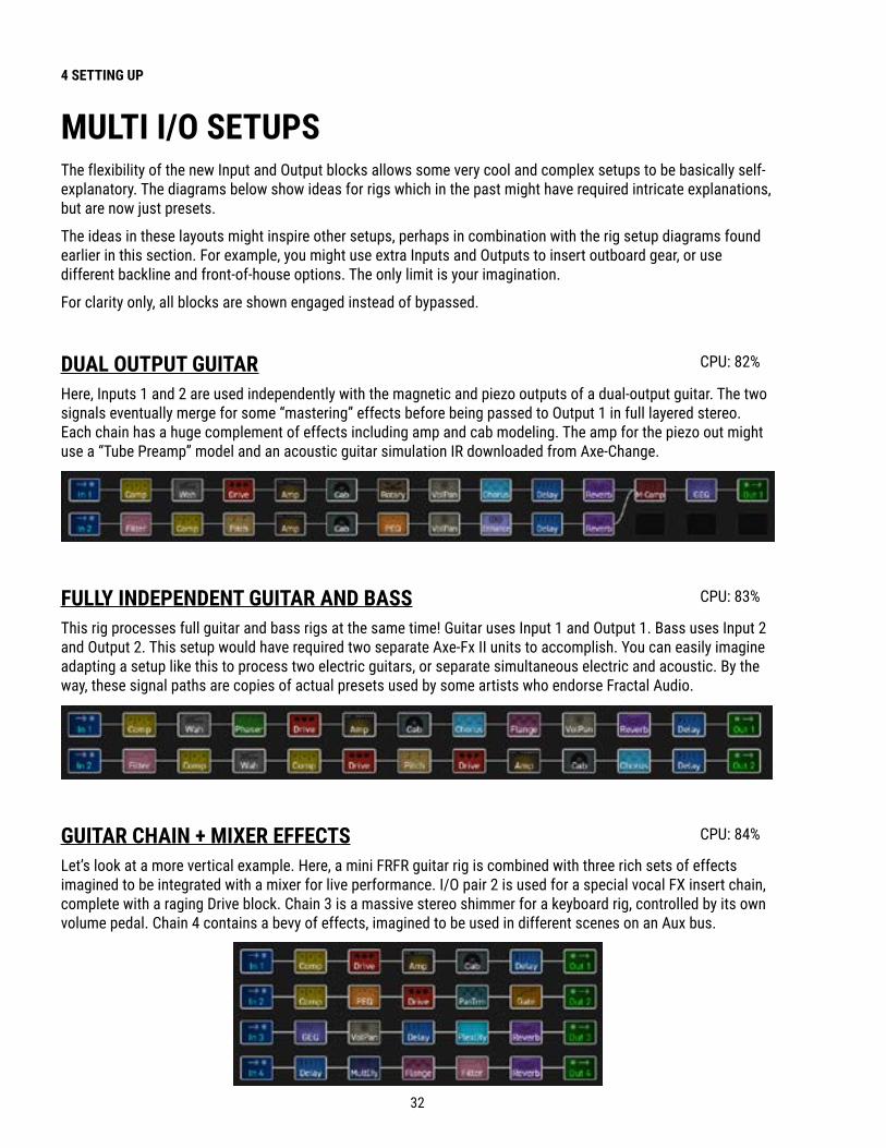
32
4 SETTING UP
MULTI I/O SETUPSThe flexibility of the new Input and Output blocks allows some very cool and complex setups to be basically self-explanatory. The diagrams below show ideas for rigs which in the past might have required intricate explanations, but are now just presets.
The ideas in these layouts might inspire other setups, perhaps in combination with the rig setup diagrams found earlier in this section. For example, you might use extra Inputs and Outputs to insert outboard gear, or use different backline and front-of-house options. The only limit is your imagination.
For clarity only, all blocks are shown engaged instead of bypassed.
DUAL OUTPUT GUITARHere, Inputs 1 and 2 are used independently with the magnetic and piezo outputs of a dual-output guitar. The two signals eventually merge for some “mastering” effects before being passed to Output 1 in full layered stereo. Each chain has a huge complement of effects including amp and cab modeling. The amp for the piezo out might use a “Tube Preamp” model and an acoustic guitar simulation IR downloaded from Axe-Change.
CPU: 82%
FULLY INDEPENDENT GUITAR AND BASSThis rig processes full guitar and bass rigs at the same time! Guitar uses Input 1 and Output 1. Bass uses Input 2 and Output 2. This setup would have required two separate Axe-Fx II units to accomplish. You can easily imagine adapting a setup like this to process two electric guitars, or separate simultaneous electric and acoustic. By the way, these signal paths are copies of actual presets used by some artists who endorse Fractal Audio.
CPU: 83%
GUITAR CHAIN + MIXER EFFECTSLet’s look at a more vertical example. Here, a mini FRFR guitar rig is combined with three rich sets of effects imagined to be integrated with a mixer for live performance. I/O pair 2 is used for a special vocal FX insert chain, complete with a raging Drive block. Chain 3 is a massive stereo shimmer for a keyboard rig, controlled by its own volume pedal. Chain 4 contains a bevy of effects, imagined to be used in different scenes on an Aux bus.
CPU: 84%
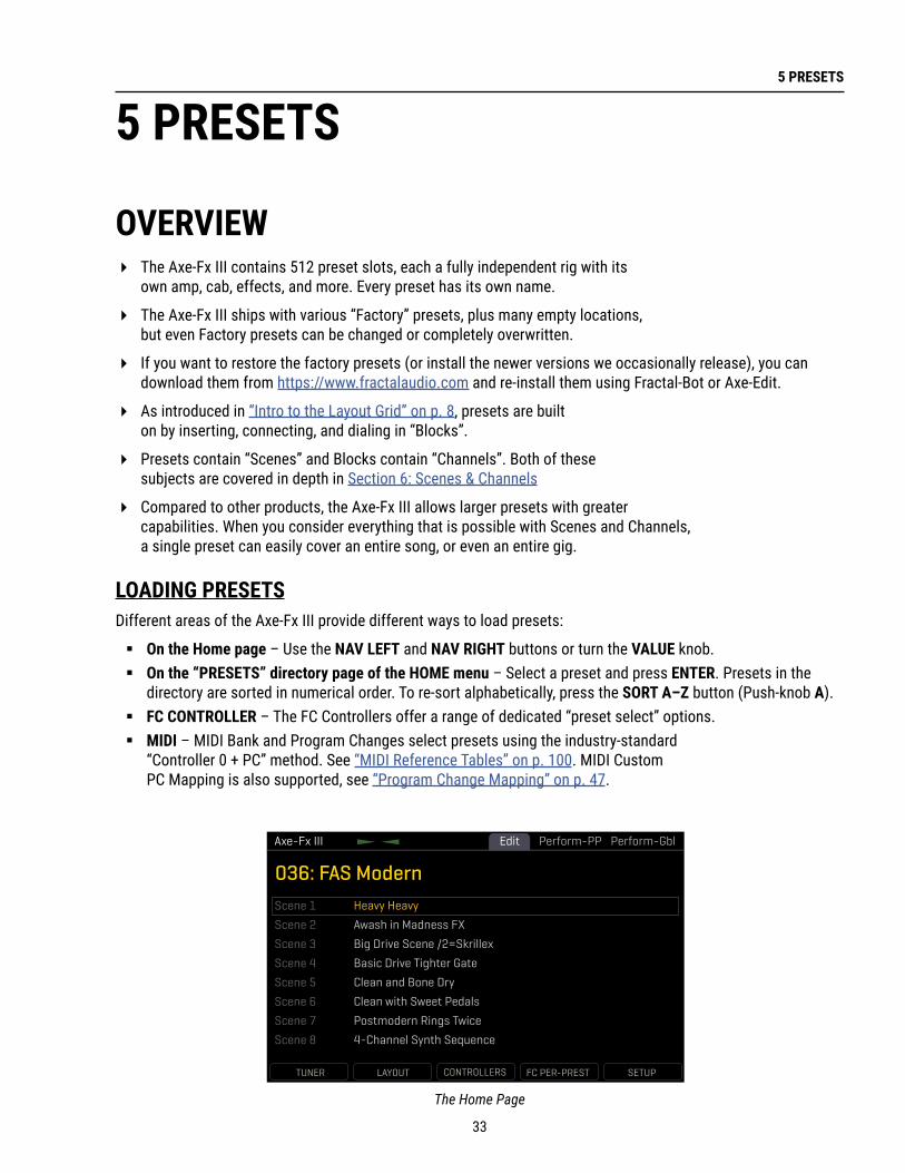
33
5 PRESETS
OVERVIEW � The Axe-Fx III contains 512 preset slots, each a fully independent rig with its
own amp, cab, effects, and more. Every preset has its own name.
� The Axe-Fx III ships with various “Factory” presets, plus many empty locations, but even Factory presets can be changed or completely overwritten.
� If you want to restore the factory presets (or install the newer versions we occasionally release), you can download them from https://www.fractalaudio.com and re-install them using Fractal-Bot or Axe-Edit.
� As introduced in “Intro to the Layout Grid” on p. 8, presets are built on by inserting, connecting, and dialing in “Blocks”.
� Presets contain “Scenes” and Blocks contain “Channels”. Both of these subjects are covered in depth in Section 6: Scenes & Channels
� Compared to other products, the Axe-Fx III allows larger presets with greater capabilities. When you consider everything that is possible with Scenes and Channels, a single preset can easily cover an entire song, or even an entire gig.
LOADING PRESETSDifferent areas of the Axe-Fx III provide different ways to load presets:
� On the Home page – Use the NAV LEFT and NAV RIGHT buttons or turn the VALUE knob. � On the “PRESETS” directory page of the HOME menu – Select a preset and press ENTER. Presets in the
directory are sorted in numerical order. To re-sort alphabetically, press the SORT A–Z button (Push-knob A). � FC CONTROLLER – The FC Controllers offer a range of dedicated “preset select” options. � MIDI – MIDI Bank and Program Changes select presets using the industry-standard
“Controller 0 + PC” method. See “MIDI Reference Tables” on p. 100. MIDI Custom PC Mapping is also supported, see “Program Change Mapping” on p. 47.
5 PRESETS
Perform-GblPerform-PPAxe-Fx III
036: FAS Modern
TUNER LAYOUT CONTROLLERS FC PER-PREST SETUP
Edit
Scene 1
Scene 2
Scene 3
Scene 4
Scene 5
Scene 6
Scene 7
Scene 8
Heavy Heavy
Awash in Madness FX
Big Drive Scene /2=Skrillex
Basic Drive Tighter Gate
Clean and Bone Dry
Clean with Sweet Pedals
Postmodern Rings Twice
4-Channel Synth Sequence
The Home Page

34
5 PRESETS
THE LAYOUT GRID The grid is a 14×6 framework used for building presets. The grid is made up of spaces or slots into which blocks are inserted to set up signal flow. Cables connect blocks. Grid spaces and cables are stereo, though not every block processes audio in stereo.
Access the grid from the Home page by pressing the ENTER button or the LAYOUT Push-knob.
In the default view, the Axe-Fx III display shows only a 6×6 section of the 14×6 grid. Navigate to off-screen areas using the D or E knobs, or the NAV buttons. A bottom scrollbar indicates where you are in the overall left-to-right layout. To show the entire grid at once, zoom out with the ZOOM button (Push-knob A).
WORKING WITH BLOCKSAs explained in “Intro to the Layout Grid” on p. 8, the Axe-Fx III grid must be populated with Blocks.These come from a large inventory of amps, cabs, stompboxes, studio effects, and more. To interact with the grid you must move the cursor — a yellow rectangle controlled by the D or E knobs, or the NAV buttons. For simplicity, we’ll refer simply to these controls as “NAV” going forward.
TO INSERT A BLOCK… � NAV to the desired grid location. � Turn the VALUE wheel to step through the list of blocks, including options for SHUNT (see below) and NONE. � Press ENTER to confirm or EXIT to cancel changes. � Every preset has its own complete inventory of blocks. Using a block in
one preset does not make it unavailble to other presets.
TO CHANGE OR REMOVE AN EXISTING BLOCK… � Select the block and turn VALUE to change it to the desired type. To REMOVE a block, select “NONE”. � Press ENTER to confirm or EXIT to cancel changes.
The grid normally shows six rows and six columns. You can scroll left or right with navigation controls.
Zoom out to show the entire grid at once. This also reveals VU meters for leveling scenes and presets.
ToolsMetersAxe-Fx III
ZOOM BYPASS DELETE CABLE CONTROLLERSScene: 1 Channel Block Level Row Column
Edit ToolsMetersLayout CPU
1L1R
4.0%
ZOOM BYPASS DELETE CABLE CONTROLLERSScene: 1 Channel Block Level Row Column
EditCPU 4.0%
1L1R
A shortcut makes it easy to remove an existing block or convert it to a shunt. Select the block and press the DELETE button (Push-knob C). A deleted block is replaced by a shunt. Delete any shunt to leave an empty space.

35
5 PRESETS
TO BYPASS OR ENGAGE A BLOCK… � Use NAV buttons to select the block. � Press the BYPASS button (Push-knob B). Bypassed blocks are grayed out (dimmed).
SHUNTS A shunt is a sonically transparent block—a mere tool which carries signal through otherwise empty grid locations. Your preset will be silent unless you make a complete connection from the Input block to the Output block, so place a shunt wherever you don’t use another block like an Amp, Cab, or effect. Like grid spaces, a shunt is stereo; you don’t need two for left/right. Shunts do use a small amount of CPU, so don’t overdo it.
TO INSERT A SHUNT… � NAV to the desired grid location and turn VALUE until “SHUNT” is displayed. � Press ENTER to confirm or EXIT to cancel changes.
INPUTS AND OUTPUTSInput and Output blocks are required to place input signals on the grid or pass signal to output jacks. All factory presets use Input 1 and Output 1. Other setups may require different Input and Output blocks. See “The Fractal Audio Blocks Guide” for additional information.
BLOCK DISPLAY TYPES The color display shows different grid block states as follows:
AMPIN 1 1A CABDRV 1
A OUT 11A
Bypassed Selected Normal Shunt OutputInput
GLOBAL BLOCKSGlobal Blocks allow settings for a given block instance to be automatically synchonized across multiple presets. For example, a global AMP block could be used in several presets. When any setting of that amp is changed on one, the others update automatically. See also “Global Blocks” on p. 88.

36
5 PRESETS
CONNECTOR CABLESJust like physical gear, the blocks in the Axe-Fx III need to be connected together for signal to flow. This is done using virtual cables, which run from one grid block to another. With even one connector missing, your preset may be totally silent! Like shunts, connectors are totally transparent.
TO CREATE A CONNECTOR CABLE… � On the grid, navigate to the block where you wish the cable to
BEGIN. You can’t start from an EMPTY grid space!
� Press the CABLE button (Push-knob D), or ENTER. The selected block and its neighbor to the right will alternatingly flash.
� NAV to the desired destination block, which must be in the next column to the right. � It is possible to select an empty location. A shunt will be added there if you complete the cable.
� Be sure to select a destination that is not already connected to the block you started from, or you will REMOVE that cable (see below).
� Press ENTER. To cancel without connecting, press EXIT instead.
TO REMOVE A CABLE CONNECTOR…Cables are removed in much the same way as they are created.
� On the grid, NAV to the block where the cable begins.
� Press the CABLE button (Push-knob D), or ENTER. The selected block and its neighbor to the right will alternatingly flash.
� NAV to select the “other end” of the cable you wish to remove. � Press ENTER. To cancel without removing, press EXIT instead.
SHORTCUT: To span multiple empty grid columns with a series of shunts and cables, select any block that is followed by a series of empty spaces, then press-and-hold the ENTER button. The intervening spaces will be automatically filled with shunts and connected with cables. Careful: any existing cables encountered along the way will be REMOVED!
MOVING BLOCKS, ROWS, AND COLUMNSThe Tools page of the Layout menu contains various utilities to MOVE individual blocks, rows, or columns UP, DOWN, LEFT, or RIGHT. When a block or a grid row/column is moved, it swaps places with the item in the space it is moved to. This may result in certain connector cables being modified or removed, so be sure to observe how the elements of your preset are interconnected before proceeding with a move operation.
� Open the Tools page of the Layout menu. � Select a function with the FUNCTION knob (A): Move Effect/Column/Row, Left/Right/Up/Down. � Use the NAV buttons to select the target Block, Row, or Column you wish to move. � Press ENTER to execute the move.
Remember, on the Axe-Fx III grid, each component is STEREO. Shunts, cables, and most blocks are stereo in/stereo out. The grid allows up to six full stereo paths, and you do NOT necessarily need to create parallel grid paths for stereo! Some blocks internally process audio in mono (such as Amp or Drive) but even these generally have Input Select and Output Balance parameters.

37
5 PRESETS
THE RULES OF AXE‑FX III CABLES � No cables = No sound. Even one missing link will break the chain.
� Signal flows from LEFT to RIGHT.
� A cable MUST originate from a BLOCK or a SHUNT. Empty locations are not viable origins.
� If you try to connect to an EMPTY location, a SHUNT will be created there.
� You can ONLY connect to blocks in the next column to the right.
The diagram below illustrates some of the ideas above:
� You may freely SPLIT or MERGE up to six ways at any point. This is sonically transparent and there is zero risk of signal degradation or phase problems. CROSSING is also possible. Here are some examples:
The represents the origin of a connector cable.
The shows valid possible destinations.
The symbol shows destinations that are illegal/unavailable.
Any columns farther left or right would also be illegal/unavailable.
If the were in a different ROW, every would still be in the same place.
Split Merge Cross Complex
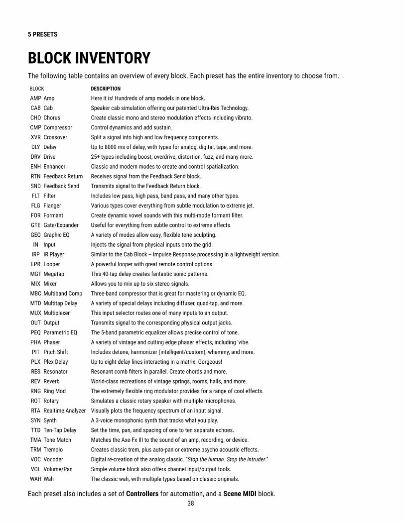
38
5 PRESETS
BLOCK DESCRIPTION
AMP Amp Here it is! Hundreds of amp models in one block.CAB Cab Speaker cab simulation offering our patented Ultra-Res Technology.CHO Chorus Create classic mono and stereo modulation effects including vibrato.CMP Compressor Control dynamics and add sustain.XVR Crossover Split a signal into high and low frequency components.DLY Delay Up to 8000 ms of delay, with types for analog, digital, tape, and more.DRV Drive 25+ types including boost, overdrive, distortion, fuzz, and many more.ENH Enhancer Classic and modern modes to create and control spatialization.RTN Feedback Return Receives signal from the Feedback Send block.SND Feedback Send Transmits signal to the Feedback Return block.FLT Filter Includes low pass, high pass, band pass, and many other types.FLG Flanger Various types cover everything from subtle modulation to extreme jet.FOR Formant Create dynamic vowel sounds with this multi-mode formant filter.GTE Gate/Expander Useful for everything from subtle control to extreme effects.GEQ Graphic EQ A variety of modes allow easy, flexible tone sculpting.IN Input Injects the signal from physical inputs onto the grid.
IRP IR Player Similar to the Cab Block -- Impulse Response processing in a lightweight version. LPR Looper A powerful looper with great remote control options.MGT Megatap This 40-tap delay creates fantastic sonic patterns.MIX Mixer Allows you to mix up to six stereo signals.MBC Multiband Comp Three-band compressor that is great for mastering or dynamic EQ.MTD Multitap Delay A variety of special delays including diffuser, quad-tap, and more.MUX Multiplexer This input selector routes one of many inputs to an output.OUT Output Transmits signal to the corresponding physical output jacks.PEQ Parametric EQ The 5-band parametric equalizer allows precise control of tone.PHA Phaser A variety of vintage and cutting edge phaser effects, including ‘vibe.PIT Pitch Shift Includes detune, harmonizer (intelligent/custom), whammy, and more.PLX Plex Delay Up to eight delay lines interacting in a matrix. Gorgeous!RES Resonator Resonant comb filters in parallel. Create chords and more.REV Reverb World-class recreations of vintage springs, rooms, halls, and more.RNG Ring Mod The extremely flexible ring modulator provides for a range of cool effects.ROT Rotary Simulates a classic rotary speaker with multiple microphones.RTA Realtime Analyzer Visually plots the frequency spectrum of an input signal.SYN Synth A 3-voice monophonic synth that tracks what you play.TTD Ten-Tap Delay Set the time, pan, and spacing of one to ten separate echoes.TMA Tone Match Matches the Axe-Fx III to the sound of an amp, recording, or device.TRM Tremolo Creates classic trem, plus auto-pan or extreme psycho acoustic effects.VOC Vocoder Digital re-creation of the analog classic. “Stop the human. Stop the intruder.”VOL Volume/Pan Simple volume block also offers channel input/output tools.WAH Wah The classic wah, with multiple types based on classic originals.
BLOCK INVENTORYThe following table contains an overview of every block. Each preset has the entire inventory to choose from.
Each preset also includes a set of Controllers for automation, and a Scene MIDI block.

39
5 PRESETS
EXAMPLE PRESET GRIDS
Ex 1: Sweet and Simple. Wah. Drive pedal. Amp and Cab. Delay and Reverb. Notice the In 1 and Out 1 blocks.
Several preset illustrations appear below, to explain how blocks are combined to form presets. These illustrations are screen-captures from Axe-Edit III, rather than representations of the small screen.
Ex 2: Here some more effects are added. Reverb is run in parallel to the delay for a different sound.
Ex 3: An entire parallel chain for a shimmery, filtered effect with a VOLUME block for its own "Send" control.
Ex 4: A complex preset with effects before and after two amps. A stereo cab feeds OUT 1 (Front of House), while Output 2 taps the signal with NO cab for use with a neutral power amp & real guitar speakers (on-stage backline).
Ex 5: A more complex preset with two amps, parallel paths, outboard gear, and 4 each of drive and delay blocks.
(This preset is the first on this page to show some blocks which are bypassed.)

40
5 PRESETS
EDITING EFFECT BLOCKSBlocks are fully programmable, meaning you can dial in every setting as desired and save the result. The Edit menu for every block contains one or more pages, each with multiple parameters to control various functions. Here’s a quick guide covering how to access and work with the different types of Edit menu pages.
OPENING AN EDIT MENU � On the Layout grid, select the desired block and press EDIT.
� OR... from anywhere, press EDIT to jump right to the Edit menu for the selected block (or the first block if none is selected).
TURNING PAGES � Some menus have multiple pages, shown as
“tabs” at the top of the menu (red arrows, right).
� Tap the PAGE buttons to page left or right.
EDITING “KNOB” PAGES � Some Edit menu pages show rows of
up to five virtual controls like knobs, switches or selectors. To make changes, use the five knobs below the display.
� You will hear all changes in real time.
� Switch between rows using NAV UP/DOWN.
EDITING “MENU” PAGES � Some pages have vertical lists of parameters.
� Use the NAV UP/DOWN buttons to step through the list or NAV LEFT/RIGHT buttons to jump.
� The A knob and the VALUE knob operate the selected parameter.
� B, C, D, and E knobs control other parameters in the list, as shown by labels on the list.
OTHER PAGE TYPES � Some pages are arranged in rows and
columns. Some include interactive meters or graphs. Use NAV and VALUE or A,B,C,D,E knobs to move around and make changes.
� For TYPE pages, such as Amp Type, just NAV through the list to make a selection. Selections take effect instantly.
Chorus 1Analog Stereo Scene: 1 Channel: A
50.0 %
RESET BYPASS MODIFIER ROW MORE 1 of 2
NumberVoices
Rate
Mix Level
Depth DelayTime
Type Basic Expert Mix
2
Tempo
2
Chorus 1Analog Stereo
Low CutHigh CutLFO PhaseLFO TypeAuto DepthPhase ReverseDriveWidthLFO2 RateLFO2 DepthStereo Spread
20.00 Hz8000 Hz90.0 degTRIANGLELOWNONE3.3350.0 %0.050 Hz0.0 %100.0 %
ABCDE
Scene: 1 Channel: A
RESET BYPASS MODIFIER ROW MORE 1 of 2
Type Basic Expert Mix
Multiband Compressor 1Scene: 1 Channel: A
RESET BYPASS MODIFIER ROW MORE 1 of 2
Config Mix
Nav Value Value Value
LOW MID HI
Low Mid HighCrossover FreqThresholdRatioAttackReleaseLevelDetectorMute
500.0 Hz-80 db1.000
10.00 ms10.00 ms
6.0 dBFast RMS
OFF
-20 db20.00
10.00 ms1000 ms-20.0 dB
Peak
10000 Hz-10 db2.000
10.00 ms500 ms
-6.00 dBRMS+Peak
--

41
5 PRESETS
SAVING CHANGESAfter making changes to a preset, you may want to save the results. Here’s how:
TO STORE A PRESET… � Press STORE to show the STORE page.
� Press ENTER to display “Do you want to overwrite the Preset?”
� Press ENTER again to confirm, or EXIT to cancel.
� The message “SAVED!” is shown when saving is complete.
Scene naming is a powerful new capability. Aside from stating what a specific scene is intended for, the names of un-used scenes can be used for short notes or reminders. Shorthand may help. For example, a “slash” could indicate expression capability on an “External” controller: “FB /1, Time /2” could show that Feedback is controlled by “External 1” and Mix by “External 2”.
What constitutes “making changes”? Obviously, parameter edits, but also changing the scene (see Section 6: Scenes & Channels), and sometimes, when new firmware requires changes to be made automatically, simply loading a preset can cause the edited light to turn on.
RESETTING A BLOCK/CHANNELUse RESET when you want a fresh start after making changes to a block.
� If it isn’t already open for editing, select the desired block on the grid and press EDIT. � Press the RESET button (Push-knob A). You are prompted to reset the current channel. � Press ENTER to confirm. You can reset other channels in a block as they are used.
Learn more about Channels in Section 6: Scenes & Channels.
TO CHANGE THE PRESET NAME OR LOCATION…The Axe-Fx III has 512 preset memory locations. You can edit the name of any preset while storing.
� Press STORE to show the STORE page.
� NAV down once to the PRESET line.
� Turn the B knob to move the cursor. � The C knob selects upper case letters. � The D knob selects lower case letters. � The E knob selects numbers. � The VALUE knob selects ALL characters, including symbols. � You can use up to 31 characters in a preset name.
� You can also NAV to any Scene name to edit it in the same way.
� Press ENTER to Store, then press ENTER again to confirm.
� The message “SAVED!” is displayed and the new location (if any) is loaded.

42
5 PRESETS
Each block you place in a preset contributes to the total CPU load for that preset. You can check the current load at any time by viewing the mini CPU meter at the top of the grid.
The maximum allowable load is about 80%, and if you manage to get much above that, audio performance may be compromised.
When inserting a new block would cause an overload, this is prevented and the message “INSUFFICIENT CPU” is displayed. It is assumed that a new block will be used to its limit when making this determination.
If you are prevented from inserting a block because of CPU limits, you can remove an unused or less important block. Adjusting certain parameters can also help. Beware of trying to set parameters back to higher values after inserting the desired block. At extremely high CPU usage levels, the Axe-Fx III may become unstable and/or Axe-Edit may stop responding.
Here are a few of the common block parameters whose settings have a measurable effect on CPU usage:
� Amp: Output Comp: Set to "0" for the least CPU usage. � Cab: Mute: The more IRs you use per block, the higher the CPU usage.
Cab Preamp and Room settings also affect CPU. � Reverb: Quality and Echo Density. Lower = less CPU. The “Spring” type uses the least CPU. � Compressor: Set Type to one of the "PEDAL" options to use less CPU. � Phaser: Stages. Lower = less CPU. � Filter: Order and Q. Lower = less CPU. � Multitap Delay: Type. Different types have different CPU requirements. � Modifiers also affect CPU usage. � Synth : More voices = more CPU.
The Fractal Audio Wiki keeps a list of CPU saving ideas. Find it at: https://wiki.fractalaudio.com/axefx2/index.php?title=Presets and_blocks.
CPU & USBWith its dedicated processor for USB, CPU usage is not increased when USB is connected.
PRESET CPU LIMITS

43
6 SCENES & CHANNELS
� Each Scene sets the Bypass state of every block in the current preset. � Each Scene sets the Channel of every block in the current preset. � Each Scene has its own levels via the Scene Level settings in every Output block. � Each scene has its own settings for four Scene Controllers (See p. 62). � Scenes can use the Scene MIDI block to send MIDI
messages. See “Sending MIDI” on p. 96 � Scenes interact with FC controller “Control Switches”
(See Section 13: FC Controllers). � Each Scene also has its own Name.
Before reading this section, please review “Intro to Scenes and Channels” on p. 9.
Every Axe-Fx III preset contains eight Scenes. Scenes don’t need to be added or created—they’re already there, ready to be used. Think of a Scene like a “preset within a preset.” Scenes control which blocks are on or off, which Channel each block is set to, and more.
There are many benefits to using Scenes. Selecting a Scene allows you to recall with one tap what would otherwise require “tap dancing” across foot switches. Scenes load instantly and changes can be gapless and seamless, and they offer the easiest way to ensure perfect “spillover” of time-based effects like delay and reverb.
The Channels feature is almost self explanatory. Most blocks have some number of channels (typically four), and for each channel you can set every parameter of that block to any setting. It’s like having multiple blocks in one.
WHAT SCENES DO NOT INCLUDE... In short? Everything else. Scenes only affect the items listed above. Scenes cannot change which blocks are placed on the grid, or change the grid routing. You cannot tweak effect parameters per Scene (except through Scene Controllers), but remember, you can switch Channels.
WHAT EACH CHANNEL INCLUDES . . . Each Channel stores its own settings for every parameter in the block. This gives you up to four independent sounds from a single block. Note that just like on a traditional pedal or processor, time-based blocks such as Delay and Reverb share one set of memory across different channels, so you may hear a “sweep” if you change time or size. To avoid this, just use different blocks from scene-to-scene.
OVERVIEW
WHAT SCENES INCLUDE...
WHY NOT JUST CHANGE PRESETS? Preset changes give you total flexibility. You can change anything and everything in every preset, but there are also
drawbacks. Synchronizing multiple presets is tedious, it takes care to get levels and spillover just right, and while preset changes are fast, Scene changes are even faster and can be seamless.
6 SCENES & CHANNELS

44
6 SCENES & CHANNELS
CHANGING CHANNELSDifferent areas of the Axe-Fx III provide different ways to change Channels:
� On the GRID – Select the desired block and turn the Channel knob (B). The current Channel is shown above the knob.
� While EDITING a BLOCK – Press the MORE button (Push-knob E) to show the Scene/Channel strip. Use the CHANNEL–/+ buttons (Push-knobs C & D) to select a channel. The current channel is shown near the top center of every page in the Edit menu.
� FC CONTROLLER – The FC Controllers offer a range of dedicated “Channel” functions. � MIDI – MIDI and other Global Controllers such as a connected external footswitch can be
used to select Channels. See “Selecting Scenes & Channels Remotely” on p. 46. � Of course, Axe-Edit can also be used to change channels.
SETTING UP CHANNELS Whenever you edit a block, you are already programming at least one Channel (usually Channel A). Programming additional channels is easy: simply select the desired channel as described above and use your usual methods to set the various parameters to their new values. Repeat for each Channel in the block and then save the preset.
TO COPY A CHANNEL…The Tools page of the Layout menu (“grid”) provides a utility to copy one Channel to another. This works within a single block only; you can’t copy a Channel from one block to another, or from one preset to another.
1 . Navigate to the Tools page of the Layout menu (grid).2 . Turn the VALUE wheel until “COPY CHANNEL” is shown on the display.3 . Use the D knob to select the scene you want to copy from. Channel letters are shown above the knobs.4 . Use the E knob to select the location you want to copy to. 5 . Press ENTER or the on-screen EXECUTE button (Push-knob C) to complete the copy.6 . Test your preset and remember to STORE to make the changes permanent.

45
6 SCENES & CHANNELS
SELECTING SCENESDifferent areas of the Axe-Fx III provide different ways to select a Scene.
� On the Home page – Use the NAV UP/DOWN buttons or turn Push-knob A. The current scene is highlighted. � On the GRID – Turn the Scene knob (Push-knob A). The current scene is shown above the knob. � While EDITING a BLOCK – Press the MORE button (Push-knob E) to show the Scene/Channel strip.
Use the SCENE –/+ buttons (Push-knobs A & B). The current scene is shown near the top center of every page in the Edit menu.
� FC CONTROLLER – The FC Controllers offer a range of dedicated “Scene Select” functions. � MIDI – MIDI and other Global Controllers such as a connected external footswitch can be
used to select scenes. See “Selecting Scenes & Channels Remotely” on p. 46. � Of course, Axe-Edit can also be used to select Scenes.
SETTING UP SCENES When you create or edit any preset, you are working with at least one Scene. To set up additional scenes, simply select the desired Scene and use the usual methods to turn effects ON or OFF and select channels, then save your changes. Here are step-by-step instructions:
TO SET UP A NEW SCENE OR EDIT AN EXISTING ONE…1 . Load the desired preset and select the desired Scene.2 . Bypass or engage each block as desired.
� On the Layout (grid) or while editing any block, use the BYPASS button (Push-knob B). � Or use any assigned footswitch or remote controller to bypass/engage the block.
3 . Set the Channel for each block as described on the previous page.4 . Test and save your preset. On the STORE page, NAV to your new scene and give it a name (see p. 41).
Always carefully test ALL scenes in your preset—even those you think you might not use. Ensure that there are no undesired volume jumps or other surprises waiting to happen.
TO COPY ONE SCENE TO ANOTHER…The Tools page of the Layout menu contains a tool to copy one scene to another. (not including the scene name). This works within a single preset; you can’t copy a scene from one preset to another.
1 . Navigate to the Tools page of the Layout menu (grid).2 . Turn the VALUE wheel until “COPY SCENE” is shown on the display.3 . Use the D knob to select the scene you want to copy from. Scene numbers are shown above the knob.4 . Use the E knob to select the location you want to copy to. You can also choose to copy one scene to “ALL”.5 . Press ENTER or the on-screen EXECUTE button (Push-knob C) and the copy operation is completed.6 . Test your preset and remember to STORE to make the changes permanent.Axe-Edit makes it even easier to set up and copy scenes, with useful tools and a dedicated “Scenes Manager .”
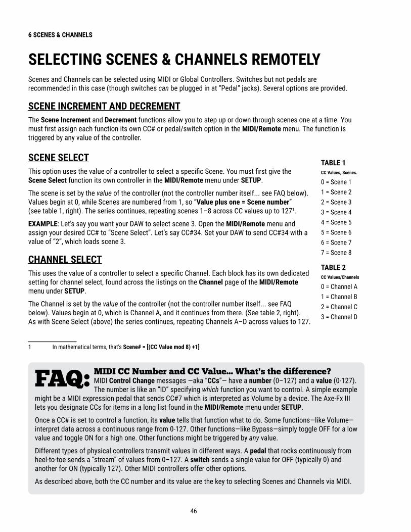
46
6 SCENES & CHANNELS
SELECTING SCENES & CHANNELS REMOTELYScenes and Channels can be selected using MIDI or Global Controllers. Switches but not pedals are recommended in this case (though switches can be plugged in at “Pedal” jacks). Several options are provided.
SCENE INCREMENT AND DECREMENTThe Scene Increment and Decrement functions allow you to step up or down through scenes one at a time. You must first assign each function its own CC# or pedal/switch option in the MIDI/Remote menu. The function is triggered by any value of the controller.
SCENE SELECTThis option uses the value of a controller to select a specific Scene. You must first give the Scene Select function its own controller in the MIDI/Remote menu under SETUP.
The scene is set by the value of the controller (not the controller number itself... see FAQ below). Values begin at 0, while Scenes are numbered from 1, so “Value plus one = Scene number” (see table 1, right). The series continues, repeating scenes 1–8 across CC values up to 1271.
EXAMPLE: Let’s say you want your DAW to select scene 3. Open the MIDI/Remote menu and assign your desired CC# to “Scene Select”. Let’s say CC#34. Set your DAW to send CC#34 with a value of “2”, which loads scene 3.
CHANNEL SELECTThis uses the value of a controller to select a specific Channel. Each block has its own dedicated setting for channel select, found across the listings on the Channel page of the MIDI/Remote menu under SETUP.
The Channel is set by the value of the controller (not the controller number itself... see FAQ below). Values begin at 0, which is Channel A, and it continues from there. (See table 2, right). As with Scene Select (above) the series continues, repeating Channels A–D across values to 127.
1 In mathematical terms, that’s Scene# = [(CC Value mod 8) +1]
MIDI CC Number and CC Value... What's the difference? MIDI Control Change messages —aka “CCs”— have a number (0–127) and a value (0-127). The number is like an “ID” specifying which function you want to control. A simple example
might be a MIDI expression pedal that sends CC#7 which is interpreted as Volume by a device. The Axe-Fx III lets you designate CCs for items in a long list found in the MIDI/Remote menu under SETUP.
Once a CC# is set to control a function, its value tells that function what to do. Some functions—like Volume— interpret data across a continuous range from 0-127. Other functions—like Bypass—simply toggle OFF for a low value and toggle ON for a high one. Other functions might be triggered by any value.
Different types of physical controllers transmit values in different ways. A pedal that rocks continuously from heel-to-toe sends a “stream” of values from 0–127. A switch sends a single value for OFF (typically 0) and another for ON (typically 127). Other MIDI controllers offer other options.
As described above, both the CC number and its value are the key to selecting Scenes and Channels via MIDI.
TABLE 1 CC Values, Scenes .
0 = Scene 11 = Scene 22 = Scene 33 = Scene 44 = Scene 55 = Scene 66 = Scene 77 = Scene 8
TABLE 2 CC Values/Channels
0 = Channel A1 = Channel B2 = Channel C3 = Channel D

47
6 SCENES & CHANNELS
PROGRAM CHANGE MAPPINGAnother way to select Scenes via MIDI is using Custom PC Mapping, which allows a single incoming MIDI Program Change (PC) message to select your choice of both Preset and Scene. This is a popular option in cases where a connected MIDI foot controller lacks the sophistication to transmit the MIDI messages required for scene selection.
The PC Mapping parameter on the General page of the MIDI/Remote menu under SETUP must be enabled for custom mapping to be in effect. With this option set to “ON”, an internal table re-maps each incoming MIDI Program Change message so it can load your choice of preset and scene. The map is limited to 128 entries so MIDI BANK SELECT messages are ignored while PC Mapping is enabled.
With PC Mapping option set to “OFF”, MIDI Program Changes load presets on a 1:1 basis and Bank Select commands are processed as usual as per “MIDI Reference Tables” on p. 100.
BUILDING THE MAPThe mapping table is on the Mapping page of the MIDI/Remote menu under SETUP.
To use it, follow this simple process:
1 . NAV to the row for whichever Program Change message you want to re-map.
2 . Use the B knob to set the desired value for Map to Preset. This is the preset that will load when the selected Program Change message is received.
3 . Use the C knob to set the desired value for Map to Scene. You can choose a scene by its number, or select “AS SAVED” to load the default scene saved in your preset. (see p. 45 for more on Default Scene).
4 . Repeat steps 2 through 4 for any remaining Program Change messages you wish to remap.
5 . EXIT when finished. You do not need to store settings in the SETUP menu.
The custom map parameters remain intact even if you switch PC Mapping Off.
SENDING MIDI WITH SCENESScenes can also transmit MIDI. See “Sending MIDI” on p. 96.
SCENE LEVELSEach of the Output blocks includes eight parameters that allow you to cut or boost the level for any scene. Using these adjustments is a quick way to balance or boost scene levels when other level options are not available.
THE DEFAULT SCENEWhen a new preset is loaded, it automatically starts on whichever Scene that was selected when that preset was last saved. To set the default scene for any preset, simply select the desired Scene and then save the preset.
You can also select a fixed “Default Scene” under Setup: Global Settings: Config. This overrides the last-saved scene and causes your selected scene to load first for all presets.

48
6 SCENES & CHANNELS
SCENES, CHANNELS & MODIFIERSThe Modifier system provides extensive automation and remote control of parameters on the Axe-Fx III.
Modifiers are detailed in Section 9 on p. 53 but here is a summary of important information about Scenes, Channels, and modifiers.
SCENE CONTROLLERS Block parameter values are the same in every Scene of a preset. Of course, you can change the Channel, which is great but not the same thing. The Scene Controller system, however, provides a way for individual parameters or groups of parameters to have different values in every scene.
See “Tutorial: Scene Controllers” on p. 62.
CHANNELS & MODIFIERSModifiers are shared across Channels, meaning that any modifier you create in one channel will be present on all channels of that block. This is a great convenience in most cases, avoiding the need to apply the same modifier multiple times as you change channels.
In some cases, you may notice that if you change an effect Type from one channel to the next, certain parameters are either not present at all, or appear with different names. For example, in the Delay block, the Mono Tape delay has a parameter called “Head 2 Ratio”, while this same parameter is called “L/R Time Ratio” in the Dual Delay. These differences are such that results should not be unpredictable.
Ex 1: SCENE REVERT OFF (default)1. You load SCENE 1. DRIVE 1 is OFF.
2. You turn DRIVE 1 ON with a Footswitch.
3. You change to SCENE 2.
4. You change BACK to SCENE 1.
5. Drive will be ON as you last left it.
Ex 2: SCENE REVERT ON1. You load SCENE 1. DRIVE 1 is OFF.
2. You turn DRIVE 1 ON with a Footswitch.
3. You change to SCENE 2.
4. You change BACK to SCENE 1.
5. Drive will be OFF as you last saved it.
SCENE REVERTScene changes you make from the Axe-Fx III front panel (or Axe-Edit III) remain in effect until you save them or discard them by loading a different preset without saving. Changes made via footswitches or MIDI, however, may work differently, depending on a Global setting called Scene Revert. With Scene Revert turned on, Scene changes are discarded as soon as you load a new Scene. Here are two examples so you can compare how Scene changes work in both modes:
TO ENABLE/DISABLE SCENE REVERT…1. Page to the General page of the MIDI/Remote menu under SETUP.
2. NAV to SCENE REVERT and set it “ON” or “OFF” as desired.
3. EXIT to finish. (You do not need to STORE changes in SETUP.)
49
7 LEVELING PRESETS
7 LEVELING PRESETS
This section is about balancing levels across Presets, Scenes and Channels. It is not about correctly setting overall input and output levels.
Balancing levels requires both knowledge and tools. The challenge of getting levels “right” is not unique to the Axe-Fx III. Guitar players and audio technicians face the same obstacles when using traditional equipment: our hearing, speakers, and surroundings are all variable. On a platform as powerful and flexible as the Axe-Fx III, the number of options that affect volume can be daunting, but fortunately there are some good rules of thumb, all backed by a number of precision controls and meters. This section aims to provide a method you can rely on to normalize the levels of Presets, Scenes and Channels.
GENERAL PRINCIPLES � Our ears deceive us. The “equal-loudness contour” or “Fletcher Munsen” effect causes
us to hear tonal balance differently as volume levels change. At lower volumes, low and high frequencies seem to be relatively quieter. Check your sounds at various levels, especially “gig” volume, and strive to learn more about this phenomenon.
� Different speaker systems have different frequency response, which affects our perceptions of tone and volume. Set levels on the same system you will perform through — ideally, the best and most accurate speakers you can attain. Be prepared to make adjustments on other systems, and this goes for your tone as well as your levels.
� Context, including other sounds and the environment itself, also change perceptions of loudness. Two different guitar sounds may seem to be equal in level when you audition them alone, but might then sound totally different when they are “competing” in a mix against other instruments such as bass and drums, or when played in a problematic performance space. Don’t be surprised if you work alone to level sounds and then find things sound different on stage.
THE RULE OF THUMBChallenges aside, it’s important that you know how to adjust levels on the Axe-Fx III.
� There are a lot of different ways to adjust level on the Axe-Fx III. A good rule of thumb is to use the Level parameter of the Amp block. See “The Method” on the next page for an a process that works across Presets, Scenes and Channels.
� Above all, use common sense. Rely on meters, but don’t set levels solely on how they look. USE YOUR EARS!
EXCEPTIONS TO THE RULE � When following the Amp block(s) with any level-dependent dynamic effects, such as a compressor
or gate, you will need to re-adjust those blocks after changing amp levels. A better option may be to “bend” the rule of thumb and adjust the output of the last dynamics block instead.
� This is also the case for any nonlinear effects such as drive which may in rare cases (such as Tape Saturation or Bitcrusher effects) be placed after the amp. Adjust Level for these blocks instead of the amp.
� If you have prominent Drive/Saturation in the Preamp simulation of the Cab block, adjust the Level of the Cab block instead.

50
7 LEVELING PRESETS
A METHOD FOR LEVELINGThe grid provides excellent tools for leveling presets, scenes, and channels. While the grid is zoomed out (press knob A) you will see VU meters for Outputs 1 and 2 at the top of the display. The scale of these meters is -20 to +10 dB with a red line at 0. (This is the internal level, NOT a dBu reading.) These meters are great for setting levels.If you page from the Edit page to the Meters page, input (blue) and output (green) meters on each individual block will help you spot any trouble or gain staging issues.
To set levels, play your guitar and watch the top VU meters. Remembering the rule of thumb (see previous page) navigate to the Amp block and adjust its level by turning the Block Level knob (C). The VU meter should hover around at the red line. Different types of playing and different amp models and settings will activate the meter in different ways. “Chugs” for instant, will usually hit the hardest. If you want to compare the levels of two presets/scenes/channels, play the same type of material while watching the meters. Remember the principles on the previous page; trust the meters, but use common sense.
TIP: When using two Amp blocks at the same time, you may find it easier to adjust levels in a single block which sums their outputs, such as a Cab, Mixer, or Volume.
The Layout view allows you to change Scenes (knob A) and Channels (knob B), so you can compare and adjust everything all within a single page.
LEADS AND LOUDER SOUNDSGiven a method established for normalizing the level across Presets, Scenes, and Channels, what if you specifically want some sounds to be louder or quieter than others? The best approach is to not boost the loudest sound but to make the others quieter. This helps prevent clipping that might happen if you make some sounds too loud. When using this method, use the meters and your ears. It is perfectly fine for some tones to appear very quiet; Fractal Audio products have an excellent signal to noise ratio and do not suffer internally from the same degree of problems as analog gear when operating at lower than ideal levels.
Make it easier to adjust levels by using the Looper block to “play” while you operate the level controls. Place the looper between the input and your first block.
ToolsMetersLayout CPU 47.5 %
ZOOM BYPASS DELETE CABLE CONTROLLERSScene: 1 Channel Block Level Row Column
EditToolsMetersLayout CPU
OUT1LOUT1R
-3.00 dB-3.00 dB
-30.0 dB-30.0 dB
OUT2LOUT2R
OUT1LOUT1R
OUT2LOUT2R
47.5%
ZOOM BYPASS DELETE CABLE CONTROLLERSScene: 1 Channel Block Level Row Column
Edit
IN 1 CMP WAH PHR DRV AMP CAB DLY CHO FLG ROT REV OUT 1
The zoomed out grid shows VU meters atop the screen. Page right to the Meters page for block meters.

51
7 LEVELING PRESETS
BLOCK BYPASS LEVELSNot just amps and cabs, but block effect settings also contribute to preset levels. Here are some tips to help dial in effects, so that levels can remain consistent as you bypass or engage blocks.
� Learn more about Bypass Modes in “The Fractal Audio Blocks Guide”
� Sometimes, effects are intended specifically to boost or cut levels. Other times, you want the volume to stay the same as an effect is dialed in. In either case, there’s an easy method you can use to make correct settings. First, with the effect engaged, dial in the Mix so the blend of wet and dry sounds is as desired. Then, with one hand on the block’s Level parameter and the other on its Bypass button (Push-knob B), switch the effect on and off, making level adjustments until the desired volume is achieved when the effect is engaged.
� Time-based effects like delay and reverb are usually best with their Bypass Mode set to “MUTE FX IN”. This ensures that dry levels remain consistent when you engage or bypass the block. Because this setting masks possible changes to your “dry” signal, you should use the Meters page of the Layout menu to ensure that the level is roughly the same before and after these effects when they are bypassed.
� Pitch effects require special consideration. Depending on their particular type and settings, you may wish to treat them like a time-based effect with the “MUTE FX IN” setting, or you may wish to set Bypass Mode to “THRU” and use the first method.

52
8 BLOCKS GUIDE
8 BLOCKS GUIDETHE FRACTAL AUDIO BLOCKS GUIDEThe FM3 is based on our flagship rackmount processor, the award-winning Axe-Fx III. Both the FM3 and the Axe-Fx III use presets built from blocks, and the blocks on both devices share many of the same parameters and settings. A separate manual covers these blocks in complete detail. More than a simple reference, it contains background information, tips, and extra material to help you make the most of your Axe-Fx or FM3.
The Fractal Audio Blocks Guide can be downloaded from https://www.fractalaudio.com/fas-bg
Blocks Guide

53
9 MODIFIERS
Modifiers allow sound parameters to be automated or remote controlled in real time. For example, you might use an expression pedal to operate a wah, use an LFO to oscillate a filter, or use MIDI to adjust a reverb. Modifiers are easy to use for common applications, but also have deep potential for extremely intricate creations.
CREATING A MODIFIERThe process of creating a modifier begins at the parameter you want to control. Parameters that can be controlled are marked with a circular symbol, shown below on a knob and a switch. When a modifier is already present, the circle will be solid yellow, like an LED that has been turned ON. You will see the same symbol whether the target parameter is on a knob page, on a text page, or any other type of menu.
The open circle means you can add a
modifier here.
The filled circle means a modifier is
already present.
Here, a switch instead of a knob allows a modifier.
This parameter has no option for a
modifier.
TO CREATE A MODIFIER . . . � Select any parameter that supports a modifier. � Press the ENTER button or press MODIFIER (Push-knob C) to show the Modifier menu. � This menu has two pages. The first is the Source page, which determines which control SOURCE should
affect the parameter. Select a Source, such as “External 1” or “LFO1”. (Learn more about Sources on p. 55.) � Press PAGE RIGHT to switch to the Modify page. This page contains all of the parameters related to the
interaction of the source and the parameter. Learn more about Modifier parameters on p. 56. At a minimum, check that MIN and MAX are set to the lowest and highest values desired. You can test at any time.
� Press EXIT to leave the modifier menu. � Test your modifier. Modifiers animate on-screen knobs, faders switches and graphs.
For text-only menu parameters, a bar graph shows the value of the source. � Modifier changes are saved when you STORE the preset.
TO EDIT OR REMOVE A MODIFIER… � To edit an existing modifier, use the same process as creating a modifier.
� To remove a modifier, change its SOURCE to “NONE”.
9 MODIFIERS
Level Bright
ON
Balance Treble

54
9 MODIFIERS
Here is a basic step-by-step tutorial on setting up a modifier for a classic Wah pedal.
For this example, we assume:
� A Wah block is already in your preset (if not, see � ou have an Expression pedal ready (see p. 12 for how to connect pedals directly to the Axe-Fx III, or
Here are the steps:
1. On the Grid, NAV to your Wah block and press EDIT to show its menu.
2. Turn to the Config page of the Wah block’s Edit menu.
3. Notice the yellow Modifier dot symbol beneath the on-screen Wah Control parameter.
4. NAV to select that parameter (or just give its knob a twiddle). It will be highlighted when selected.
5. Press ENTER or the MODIFIER Push-knob to show the Modifier menu.
6. On the Source page, change the SOURCE to your pedal. Depending on how your pedal is connected this might be “Pedal 1” (the on-board expression jack of the Axe-Fx III), or it might be one of the “External Controllers” (p. 61), or it might be one of the “FC” pedal options.
7. Test! The Wah should work when you move the pedal. You’ll also see the dot move on the graph. If it doesn’t work, check your source or make sure the pedal is properly connected and calibrated.
8. Save the preset by pressing STORE, ENTER, ENTER.
MODIFIER TIPS AND TRICKS � The same source can be assigned to multiple modifiers at the same time. For example, one
pedal can adjust Chorus Rate and Chorus Depth at the same time — even in different ways.
� The modifiers for a given block will normally be shared across all of its channels, but you can also limit a modifier so it applies only to any one channel—your choice. Change the “Channel” setting inside the modifier menu to do so.
� Modifiers use a very small amount of CPU power while you use them. Test any presets which seem close to the edge.
� All of the Internal Controllers (Tempo, LFOs, ADSRs, etc.) are part of a Controllers block. This block has four channels, so you can have up to four different sets of Controller values in one preset.
� The Axe-Fx III has a dedicated Bypass parameter in every block that can be bypassed, and this parameter allows you to assign a modifier. Bypass Mode is not used as it was on previous Fractal Audio products.
The Wah in this example is controlled by an expression pedal. An expression pedal can be used to control other parameters like whammy control, rotary rate, delay feedback, and many, many more.
There are also many different sources we could use instead of a pedal. Try an LFO for a modulating auto-wah, or an Envelope Follower for some funky Mu-Tron action. And MIDI opens up a world of controller options.
MODIFIER TUTORIAL: WAH PEDAL
WahControl

55
9 MODIFIERS
There are over 60 different choices to use as modifier sources.
INTERNAL CONTROLLERSInternal controllers are a part of every Axe-Fx III preset. You will find one Tempo, two LFOs (Low Frequency Oscillators), two ADSRs, a Sequencer, a Pitch Detector, an Envelope Follower, four Scene Controllers five Manual Controllers. (See p. 59).
To show the Controllers menu, press the CONTROLLERS button on the Home page (Push-knob C) or Layout menu (E), or press the TEMPO button once.
ONBOARD & FC PEDALS & SWITCHESThe Expression jacks of the Axe-Fx III and the Pedal or Switch jacks of a connected FC-6 or FC-12 can be assigned directly as modifier sources. In comparison to previous products, it is no longer necessary to assign these to an External Controller first (though this is still possible).
Control Switch functions allow the switches of a connected FC to be used directly as modifier sources.
EXTERNAL CONTROLLERSExternal controllers are modifier sources which in turn have their own global assignments to determine what controls them. The sixteen external controllers can each be indivudually assigned to your choice of:
� Any MIDI Control Change (CC#) message. � One of the onboard Expression (Pedal) jacks. � One of the Pedal or Switch jacks of a connected FC
series controller.
MODIFIER SOURCES OVERVIEW
LFO 1
Sequencer Pitch Envelope Scene Ctrl
LFO 2 ADSR 1 ADSR 2
Ext 1 Ext 2 Ext 3 Ext 4
Ext 5 Ext 6 Ext 7 Ext 8
Ext 9 Ext 10 Ext 11 Ext 12
Ext 13 Ext 14 Ext 15 Ext 16
External Controllers are a great choice for presets you might share, because different people will use different controllers in different setups.
For example: you send your friend a preset containing a Wah operated by External 1. On your system, External 1 is globally assigned to “PEDAL 1”— one of the onboard expression jacks. On your friend’s system, External 1 is assigned to “CC#16” because an older MIDI controller is being used. The Wah works perfectly on both rigs with no changes required!
Learn more about External controllers on p. 61.

56
9 MODIFIERS
MODIFIER PARAMETERSThe Modify page of the modifier menu contains parameters to determine the nature of the relationship between the source and the parameter. By default, a modifier is linear: the parameter value moves in direct proportion to the source. By changing this relationship, you can create a variety of desirable effects. For example, you might adjust the “taper” of the change, reverse its effect, or smooth the changes over time. Here is an overview of the additional parameters you can use to create these effects and many more.
Min and Max determine the range of parameter change. These are extremely important parameters.
EXAMPLE: The modifier for a pedal controlling Delay Feedback has Min at “10%” and Max at “50%”. The feedback sweeps only from 10% to 50 as the pedal is moved, even though this parameter’s actual range is from -100% to +100%.
Start, Mid, End, Slope, Scale, and Offset are used to create custom curves which re-map the source to the target. On the Modify page, a graph shows the relationship between the source (x-axis) and the parameter (y-axis). A dot on the graph tracks the source.
The default settings (first graph below) create a 1:1 linear relationship (the blue line) between source and parameter. As the source changes, the parameter tracks it directly.
The second two graphs below show just a few examples of the kinds of non-linear curves you can create using Slope, Scale, and Offset. The pages which follow contain more examples.
Attack and Release: These apply “damping” to slow the rate at which the target parameter value chases the source. Attack determines the rate of change as the source is increased, and Release controls the rate as it decreases. At low settings, these add just a little smoothing. Try settings of about 5 ms to “relax” a pedal or to ease the edges of a square LFO to eliminate clicks and pops, or use higher settings for slow, lazy changes.
Auto-Engage works with Off Value to create effects which turn ON or OFF automatically whenever the source controller is moved. This is typically used with a Wah pedal so you don’t need a toe switch. (Follow the example on p. 54 and set AUTO-ENGAGE to “SLOW POS” to try it out!) See also Auto-Engage on p. 58.
PC Reset sets the value for an external source when a preset first loads. This allows you to override the actual position of an external controller until it is moved or updated. To set the default value: after applying the modifier, exit to the Edit page. Notice that the value of that parameter can be edited as usual. If PC Reset is ON, the value you set and then save will be used from preset load until the source is changed (i.e. the pedal has been moved).
Update Rate controls how often the modifier is refreshed. The setting of slow is actually very fast, and fine for the vast majority of applications. The faster settings require additional CPU but provide even smoother sound performance when ultra fast changes are required (while using a fast LFO for instance). Check this setting if you think you hear “zipper noise” while a modifier is in use.
The Channel setting determines whether the modifier will be enabled on ALL channels or just on one channel (A,B,C or D). There are many creative uses for this, including effects which auto-engage only when set to a particular channel where their modifier is active.
Source
Para
met
er

57
9 MODIFIERS
Here is your basic “vanilla” volume pedal.
The pedal “start” (heel position) sets the volume to Min: 0.00; silent. The pedal “end” (toe down position) has the volume at Max: 10 or all the way up. As you rock the pedal forward, the dot follows the line. It moves up as it goes and the volume does too.
As we adjust Mid, the graph shows the curve. At 25%, the response is “tapered” so that with the pedal half way forward, Feedback is only 25% between Min and Max.
This type of curve provides gradual control of feedback across the lower end of the range, and then a more rapid change towards the top.
Now, something different: a “boost” pedal with Min set to 8 and Max still at 10. In the heel position, the volume will go only as low as 8, instead of 0 as in the previous example.
Here is a different twist: Min is at 10.0 — the loudest setting, while Max is at 0.0 — silent.
It looks the same, but this is a reverse volume pedal!
UNDERSTANDING MODIFIER MIN AND MAXMIN and MAX set the range of a modifier. This lets you fine-tune modifiers in very cool ways. In the example below, imagine a volume pedal with different settings. Using the principles on this page, you should be able to achieve a wide range of modifier control scenarios.
Mid: 50.0%
Start: 0.0%
End: 100.0%
Max: 10.0
Min: 0.0
Max: 10.0
Min: 8.0
Max: 0.0
Min: 10.0
USING “MID” TO CREATE BASIC CURVESLet’s imagine a modifier on the feedback of a delay to demonstrate changes to response curves. By now you should be familiar with the default settings, so let’s skip right to the curved version:
Max: 100%
Min: 0%
Mid: 25.0%
Start: 0.0%
End: 100.0%

58
9 MODIFIERS
START: 0.0%MID: 50%END: 100%SCALE: 2.0OFFSET: 100%
START: 0.0%MID: 50%END: 100%SCALE: 10.0OFFSET: 0%
START: 47.2%MID: 0%END: 60.6%SCALE: 10.0OFFSET: -100%
ADVANCED MODIFIER CURVES AND SHAPESYou can also adjust Start, End, and Slope (which introduces an “S” or “backwards S” shape). The numbers beneath each example below show the settings for Start, Mid, End and Slope. With a bit of experimentation, you will learn to achieve desired modifier effects quickly. Try dialing in the shapes below for practice:
Scale and Offset also re-map modifier response. Scale adds vertical exaggeration or compression, while Offset moves the entire curve up or down on the Y-axis. Segments outside the graph boundaries will be clipped and replaced by line segments. The examples below show some interesting possible applications.
AUTO-ENGAGE TURNS EFFECTS ON/OFF AUTOMATICALLYIf you have used a Wah pedal with no toe-switch, you will recognize “auto engage”. This type of Wah turns on automatically when you rock it forward it and then bypasses when you pull it back. Auto-Engage allows you to set up any effect like this: wah, whammy, or you name it.
Auto-Engage engages or bypasses a block when the Source of a modifier changes. Once you try it, we believe you will quickly find that this capability comfortably eliminates the need for an expression pedal “toe switch,”
Set up Auto-Enage using two parameters on the Modify page:
MODIFIERS AND CHANNELSRemember, a modifier is normally shared across all of the channels of the block where it exists. However, you can also limit it to operating on just a single channel—your choice—by using the Channel setting in the modifer menu.
Auto-Engage – Determines whether or not the block will automatically engage or bypass. FAST, MEDIUM and SLOW settings determine how quickly the effect turns ON/OFF once Auto-Engage is triggered. Use SLOW settings to “relax” auto-engage, so your effect doesn’t switch off too suddenly while you’re still using it.
� The three POSITION (“POS”) options trigger the effect based on OFF VALUE (see below). � The three SPEED (“SPD”) options engage the effect when the controller is moved quickly. � Set to “OFF” to disable Auto-Engage.
Off Value – Sets the position threshold that the source must cross for auto-engage to occur. When Off Value is set below 50%, the effect is bypassed when the controller goes below that value. If Off Value is set to 50% or higher, the effect is bypassed when the controller goes above that value.
For “heel down = bypassed”, set to 5%. For “toe down = bypassed”, try 95%.
0,75,100 50 100,50,0 50 0,100,0 50 0,50,100 0 0,50,100 100 0,25,100 10

59
9 MODIFIERS
INTERNAL CONTROLLERS
LFO1 + LFO2A Low Frequency Oscillator (“LFO”)generates control signals in the form of a variety of wave shapes. Examples of LFOs in use include the pulse of a tremolo, the back and forth sweep of a phaser, or the random filter in Ship Ahoy by Frank Zappa.
Type sets the shape. You can set the Rate or lock the LFO to the current Tempo. You can vary the overall Depth and Duty, or symmetry. The Run parameter starts and stops the LFO. This can be used to keep it from drifting out of time.
Each LFO outputs “A” and “B” signals, each of which is an independent modifier source on the list. You can change the Phase of output B with respect to A.
Quantize changes smooth waveforms into stepped ones. Try it on the “TRI” waveform for example.
TEMPO
SEQUENCER The Step-Sequencer generates control patterns by looping through 2–32 “stag-es.” You set the Value for each stage, the Number of stages, and the Rate or Tempo. The Run switch allows you to start or stop the sequence. Damping slurs the change between steps.
SCENE CONTROLLERSThe four Scene Controllers provide a way to change sound settings from one Scene to another. Think of each Scene Controller as a “virtual knob” whose setting can programmed with a different value in every Scene. By assigning this knob as a modifier source, you can create “per-scene” parameters.
For example, you might assign Scene Controller 1 to Input Drive in the Amp block with a value of 10% in Scene 1, 50% in Scene 2, 75% in Scene 3, and so on.
As with any source, a scene controller can be assigned to multiple parameters at the same time, each with its own modifier settings.
A Scene Controllers tutorial appears on p. 62. For more on Scenes, see Section 6 on p. 43.
PITCH DETECTORThe Pitch Detector analyzes the pitch of your playing and outputs a low value for low notes and a high value for high notes.
ADSR1 + ADSR2The two ADSR sources are envelope generators with Attack, Decay, Sustain and Release parameters (thus “ADSR”). The ADSR is triggered whenever the signal level exceeds its Threshold measured at the selected input (1 or 2). The envelope has three self-explanatory modes (Once, Loop, and Sustain) and can optionally be set to Retrigger every time the threshold is exceeded.
In comparison to the Envelope Follower, the ADSR envelope generator always creates the same control signal, but only triggers when you play hard enough.
ENVELOPE FOLLOWER This converts input level to a control signal, responding variably to your playing dynam-ics. The classic example is a touch-wah, where the frequency of the wah varies based on how hard you play. You can set Attack and Release times independently, set the trigger Threshold, and adjust the Gain at the trigger signal input, which can be set to Input 1 or Input 2.
Internal Controllers can be programmed per-preset for use as modifier sources. To access these parameters, push the CONTROLLERS button on the Home page (Push-knob D) or press TEMPO.
Tempo appears in the Controllers menu. For more information, see Section 10: Tempo.
The Internal Controllers menu offers four channels for four sets of independent settings for ALL of the items listed above: four tempos per preset, four sequencer settings, etc. When you change the channel, ALL of the controllers switch to the new channel and the new settings. Axe-Edit III provides a way to copy/paste Controller channels.

60
9 MODIFIERS
MANUAL CONTROLLERS The five Manual Controllers are virtual knobs with no function other than to serve as modifier sources. A Manu-al controller makes it possible, for instance, to create a “super control” where one knob operates multiple sound functions at the same time. For example, you might assign delay mix, reverb time and chorus depth parameters — all at the same time — to the “Manual 1” modifier source. Now, when you adjust Manual 1, all of the above parameters will change simultaneously as desired.
Another good use for Manual Controllers is to simulate an expression pedal when you do not have one handy.
Change the value of a Manual Knob in the Controllers menu, or, for a more accessible option, place on one of the Performance Control pages (see p. 90).
TUTORIAL: MANUAL CONTROLLERS In this tutorial, we will set up a Manual Controller to adjust the Feedback and Mix of a delay block. Load the factory preset “#022 Super Verb.”
1. The first step in using a Manual Controller is to assign it as a Modifier Source to the parameter of your choice. Enter the Layout grid of the preset, navigate to the Delay block, and press EDIT.
2. Use the PAGE buttons to locate the Config page of the Delay block.
3. NAV to the Feedback parameter and notice the open yellow modifier “ring” beneath the knob.
4. With the Feedback parameter highlighted, press ENTER to display the Modifier menu.
5. On the Source page, select Manual 1 .
6. Page right to the Modify page. Set Min to 0% and the Max to 50%
7. Press EXIT to return to the Delay menu. Notice that the open modifier symbol is now a solid yellow dot.
8. NAV downto the Mix parameter and press press ENTER to display the Modifier menu.
9. On the Source page, select Manual 1 .
10. Page right to the Modify page. Set Min to 5% and the Max to 75%
11. Now let’s try the Manual Controller. Press HOME to show the home page.
12. Press the CONTROLLERS button (Push-knob C).
13. Use the PAGE buttons to locate the Manual page of the Controllers menu.
14. Turn knob A to adjust Manual 1 and listen to your delay settings change. As the knob approaches 100%, the Delay mix increases (louder echoes) and the Feedback increases (more repeats).
15. Press STORE, ENTER, ENTER to save your work. Not only will all of the modifier settings be saved, but the position of the Manual knob as well.
16. EXTRA CREDIT: Use Axe-Edit to place your Manual 1 knob on the Per-Preset PERFORMANCE page and give it the name “Delay/Mix+FB” (See Chapter XX for more on the PERFORMANCE pages).

61
9 MODIFIERS
METRONOMEA metronome is included for convenience. The Metronome is not technically a controller, but its settings are accessed through the Tempo page of the Controllers menu. To enable the metronome press the Tempo button and adjust the level for the desired output(s). Note: the metronome levels persist across presets and are reset to OFF at power on.
EXTERNAL CONTROLLERSExternal Controllers are modifier sources that are in turn controlled themselves via external MIDI or a connected expression pedal or switch. For example, if the source of a modifier on a Wah effect is set to “External 1” and External 1 is set to “MIDI CC#16”; a connected MIDI expression pedal transmitting CC#16 then operates the Wah.
The global assignments for External Controllers are set on the External Control page of the MIDI/Remote menu under SETUP. You can assign a MIDI CC#, an on-board Expression pedal or switch, or a Pedal or Switch on a connected FC series controller. Choosing an External Controller as the source of your modifier is the same as assigning any other source (see “To Create a Modifier...” on p. 53). To change which CC# or pedal/switch operates an External Controller:
1. Open the MIDI/Remote menu in SETUP and page to External Ctrl.
2. Use NAV to select the External Controller you want to change (ex: “External Control 1”).
3. Use VALUE to change the assignment. You can also select “NONE” to disable the selected controller.
4. EXIT when finished.
EXTERNAL CONTROLLER INITIAL VALUESExternal Controllers assigned to MIDI are given a value of “0” until some MIDI data is received to change them. You can imagine how a missing or broken MIDI controller might therefore present a big problem...
The External Controller Initial Value parameters can change the startup value for a controller to 100%. Then, when the Axe-Fx III is powered on, any modifiers assigned to the missing controller will be all the way up instead of all the way down. To change the initial value for an External Controller:
� Page to the General page of the MIDI/Remote menu under SETUP.
� Use NAV to select to whichever controller you want to change (ex: “External Control 1”).
� Use VALUE to change the setting.
� EXIT when finished.
MODIFIERS LISTThe last page of the Controllers menu lists all of the modifiers in the current preset. You can jump to edit each modifier from this list by pressing ENTER.
As you’ll gather from looking at the list, the maximum number of modifiers per preset is 24.

62
9 MODIFIERS
TUTORIAL: SCENE CONTROLLERSIn this tutorial, we will set up a Scene Controller to adjust the Input Drive of an Amp block. While it is easy enough to achieve different amp sounds within a preset simply by switching the channel, this example provides an excellent and easy way to understand how Scene Controllers work.
We will begin with the Wrecker Rocket preset (#030), though any preset with an amp block could be used. For this example, we chose an amp model where the Drive parameter setting will be more pronounced, and no pre-existing scenes are set up.
1. Load the factory preset “#030 Wrecker Rocket.”
2. The first step in using a Scene Controller is to assign it as a Modifier Source to the parameter of your choice. Enter the Layout grid of the preset, navigate to the Amp block, and press EDIT.
3. Use the PAGE buttons to locate the Tone page of the Amp block.
4. NAV to the Input Drive parameter and notice the open yellow modifier “ring” beneath the knob.
5. With the Input Drive parameter highlighted, press ENTER to display the Modifier menu.
6. On the Source page, select Scene Controller 1 . We don’t need any custom settings on the Modify page.
7. Press EXIT to return to the Amp menu. Notice that the open yellow modifier symbol is now a solid yellow dot.
8. Now let’s set the values for our Scene Controller. Press HOME to show the home page.
9. Press the CONTROLLERS button (Push-knob D).
10. Use the PAGE buttons to locate the Scene Ctrl page of the Controllers menu.
11. Reading down, the Controller 1 column shows eight different values. These will set the value for our target parameter in each of the eight scenes.
12. We’ll want to change scenes as we dial in these values, so press the MORE 1 of 2 button (Push-knob E) to show the Scene/Channel selectors on the “MORE 2 of 2” strip.
13. Notice the that the current scene is shown at the top of the page. If not, use the scene buttons to select it now.
14. Dial in the Scene Controller 1 value for Scene 1. Let’s set it to about 20% for a “cleanish breakup” type of sound. Use your ears!
15. Use the Scene + button (Push-knob B) to switch to Scene 2.
16 . NAV Down to select the Scene 2 row in the Controller 1 column. Turn VALUE to set the value for Scene 2. Let’s set it to about 45% for a nice crunch. Again, use your ears.
17. Using the process in the previous step, set the value for Scene 3 to 75% and Scene 4 to 100% (or as desired).
18. Press HOME to return to the Home page. Test your first four scenes using the NAV UP/DOWN buttons.
19. Press STORE, ENTER, ENTER to save your work. If desired, enter Scene Names as outlined in “Saving Changes” on p. 41.
20. Feel free to assign other Scene Controllers to other parameters in your preset as desired.

63
10 TEMPO
Tempo is used in electronic music for synchronizing different rates and times, whether inside one machine or across several. Tempo on the Axe-Fx III allows for both internal and external synchronization, providing effects with a central BPM clock that can either run autonomously or follow the tempo of a connected device outputting MIDI Beat Clock. The Axe-Fx III does not transmit MIDI Clock itself. The Tempo can be set to any whole number value in the range 20–250 BPM. The Axe-Fx III flashes its current tempo on a front-panel LED.
THE GLOBAL TEMPOThe Global Tempo value is a system setting outside of any presets, scenes or channels. You can change it in any of several ways:
1. Tap two or more times on the front panel TEMPO button. NOTE: By default, the tempo averages across ten taps, but you can set it to use only two taps with an option found under SETUP: Global: Config: Tap Tempo.
2. Tap the TEMPO button once and use the Tempo knob (B).
3. Use an external MIDI device to transmit MIDI Clock to the MIDI IN port of the Axe-Fx III.
4. Use a MIDI CC# or external switch assigned to Tempo Tap, located on the Other page of the MIDI/Remote menu under SETUP. (See NOTE under #1 above).
Be aware that whenever you change the Global Tempo, you are also changing the current Preset Tempo, which will be saved if you store the current preset (see below). Be on guard that you don’t accidentally over-write saved tempos!
PRESET TEMPO A given preset can ignore the Global Tempo and use its own saved Preset Tempo instead. In fact, this is the default setting. Notice that a preset’s Tempo page contains two parameters: one is an actual Tempo (BPM) value, and the other is a setting called Tempo To Use, which determines what will happen when that preset is loaded.
When you load a preset whose Tempo To Use is “PRESET,” the saved Preset Tempo takes over: the tempo LED flashes accordingly and all tempo-dependent time/rate parameters are re-calculated. In fact the Global Tempo has not changed; it remains in the background and will be used when you load a different preset with Tempo to Use set to “GLOBAL”.
Be aware that whenever you alter a preset’s own Tempo, you are also updating the Global Tempo.
Remember that each of the four channels of the Controllers menu has its own settings for both Tempo (BPM) and Tempo to Use. You can use this to have some Scenes or Channels change the tempo while others do not.
TO SET “TEMPO TO USE” . . .1. Load the preset.
2. Tap once on the TEMPO button.
3. Change TEMPO TO USE as desired to either “GLOBAL” or “PRESET”.
4. STORE the preset.
10 TEMPO

64
10 TEMPO
SYNCHRONIZING SOUND PARAMETERSRates and times in a preset can be made to sync rhythmically to the Tempo by setting their corresponding Tempo parameters. This is done by selecting from a list of values, ranging from 1/64-note-triplets to double whole notes, with 76+ options in all. For example, to set the Time of a Mono Delay block to follow the quarter note pulse of the tempo, find the Tempo parameter on the Config page of the Delay block’s Edit menu and set this value to “1/4.”
The moment you assign a value for Tempo (other than “NONE”), its associated rate or time parameter is overridden and may not be changed manually — as indicated by its appearance in parentheses. To regain control of an overridden parameter, set its corresponding Tempo parameter back to “NONE”.
Almost every LFO rate and delay time parameter on the Axe-Fx III can be synced to the tempo.
TO SYNCHRONIZE A DELAY TO THE TEMPO . . . � Navigate to any type of Delay block and press EDIT to show its Edit menu.
� Find the Tempo parameter and set it to “1/4". Feel free to choose/explore other options. “1/8th dot” is also very useful and popular.
� STORE the preset.
Remember that once a Tempo has been set, you will be unable to adjust Time manually or with a Modifier.
TO SYNCHRONIZE A TREMOLO OR OTHER RATE TO THE TEMPO . . . � Navigate to the effect and press EDIT to show its Edit menu.
� Find the Tempo parameter and set it as desired. A typical value here might be “1/8th” or “1/16th”. Feel free to choose/explore other options.
� STORE the preset.
Remember that once a Tempo has been set, you will be unable to adjust Rate manually or with a Modifier.
Note that syncing an LFO to the tempo does not align the phase of that LFO to the Tempo LED, to MIDI song position pointer, or to other synchronized LFOs. You can synchronize various LFOs together by setting their RATE knobs fully counterclockwise to “LFO1 SYNC” and then syncing the LFO1 Controller to the Tempo (p. 59).

65
11 THE TUNER
The Axe-Fx III has a built-in Tuner—essential for the performing or recording musician. The tuner is easy to use and has high-resolution automatic pitch detection, a calibration control, offsets for modified tuning schemes, and the option to mute audio while tuning. Find the Tuner on the Home page by pressing TUNER (Push-knob B).
The tuner features a note name display, a “zero-center” meter, a spinning “strobe” type display and triangular indicators for sharp and flat.
ADVANCED TUNER FUNCTIONSThe actual tuner is on the Tune page of the Tuner menu. The Config and Offsets pages provide options for advanced tuner functions.
OFFSET PARAMETERSPARAMETER DescriptionE1, B2, G3, D4, A5, E6
+/- 25.00 Cts
Offsets allow the tuner to be calibrated so individual notes diverge from standard concert tuning by a defined amount. Use this for example for Buzz Feiten tuning.
11 THE TUNER
Configuration Parameters
PARAMETER Description.Source Selects which physical input the tuner should listen at.Mute
OFF/INPUT/OUTPUT
Determines how the tuner mute function works. � OFF: No mute. All signal is passed as usual when the tuner is engaged. � OUTPUT: The signal is muted at the output. Tails are silenced. � INPUT: The signal is muted at the noise gate. Tails ring out.
Display Mode
MIXED/ALL FLATS/ALL SHARPS
Determines whether the tuner shows note names for accidentals as Sharps, Flats, or a mix of both.
Calibration
430.0 – 450.0 Hz
Calibrates the tuner by setting the frequency of A4 (in the octave above middle C).
The tuner defaults to A440. Downtune
0 – 4 Semitones
The Downtune control allows for simplified tuning when tuning down one to four semitones. The Tuner display will read the non-downtuned equivalent note, i.e. if tuning down two semitones, the D will still show E. While Downtune is set to any value other than None, any blocks that utilize pitch information will also be transposed accordingly.
Use Offsets
OFF/ON
Determines whether the Offset settings (see below) are applied or ignored.

66
11 THE TUNER
MINI TUNERSFor convenience, mini-tuners appear throughout the Axe-Fx III. These consist of two green triangles to indicate when a note is flat (left lit), sharp (right lit) or in tune (both lit).

67
12 SETUP MENU
THE GLOBAL SETTINGS MENU Reminder: You do not need to store settings in the SETUP menu. EXIT twice when finished.
GLOBAL SETTINGS: CONFIG PAGE PARAMETER DescriptionPower Amp Modeling
ON/OFF
This parameter globally enables or disables power amp simulation in all Amp blocks in all presets. This capability is provided for cases when the Axe-Fx III is used with a guitar-oriented/tube power amp that contributes significantly to tone and dynamics. Having these characteristics applied twice to the sound—once in the virtual power amp and once in the real power amp—would result in an over-processed sound. All those Amp block parameters that are NOT part of the virtual power amp continue to work normally while Power Amp Modeling is turned off. Presence and Depth are disabled, and Master Volume becomes a simple volume control. Remember that like a real amp, the Axe-Fx III has separate preamp and power amp sections. When you disable Power Amp Modeling, the Amp block still models the preamp, which includes distortion, the tone stack, and more.
Cabinet Modeling ON/OFF
This parameter conveniently enables or disables Cab block processing in all presets. The Cab block will not physically appear to be bypassed, but acts exactly as if it had been replaced a shunt. Use this when you are using the Axe-Fx III with an amp powering a traditional guitar speaker cabinet, or the sound will be muffled, muddy, and boomy.
Tone Control Display
AUTHENTIC/IDEAL
This parameter governs the "Tone" page of the amp block. When set to Authentic (default) only those controls present on the actual amp are displayed. When set to Ideal all tone controls are displayed. Also, when set to Authentic, the Bass, Mid and Treble controls are reset to default values when changing models to ensure accuracy for models that may not have these controls.
Update Pre-11 .x Presets Spkr Imp Upon Load
YES, NO
This causes older presets to automatically update the Speaker Impedance Curve parameter to an appropriate value when loaded. NOTE: Setting this to YES will also cause the EDITED LED to light indicating the preset has been modified but not saved. See the "The Fractal Audio Blocks Guide" for more on Speaker Impedance Curve parameter in the Amp block.
12 SETUP MENUOpen the menu by pressing the SETUP button (Push-knob E) on the Home page. The current Firmware Version is shown at the top of the page. To enter a menu, select it with NAV and press ENTER. All changes take effect immediately without needing to be stored. The settings for Setup parameters are included in a backup of the System (see "Backing Up & Restoring" on p. 85).
THE FOOT CONTROLLERS MENUThe Foot Controllers menu is covered in its own Section on p. 78.

68
12 SETUP MENU
PARAMETER DescriptionSpillover
OFF/DELAY/REVERB/BOTH
Allows delay and reverb “tails” to ring out or spill over across Preset changes. You can select whether “DELAY”, “REVERB”, or “BOTH” effects will spill over. Setting to “OFF” causes effect tails to be cleared upon preset change. Spillover when switching Scenes or using “IA” Switches is not affected by this parameter.
See also "Spillover" on p. 95.Reverb Mix
+/- 50%
This boosts or cuts the MIX for ALL Reverb blocks in all presets. Note that this offset is NOT reflected in the value shown for the actual Reverb block MIX parameter. This feature is provided because certain dead or lively performance spaces may require more or less reverb across all presets.
Remember that MIX generally applies only to Reverb blocks which are wired in series. (Parallel reverbs typically run with MIX at 100%.)
Effects Mix
+/- 50%
Boosts or cuts the MIX of all blocks for which the GLOBAL MIX parameter is set to “ON”. This switch must be enabled on a per-block/per-preset basis and is available on the Mix page of the Edit menu for these block types:ChorusDelayFlanger
FormantMultitap DelayPhaser
PitchPlex DelayReverb
Ring ModRotaryTen-Tap Delay
This feature is provided because certain performance spaces may require more or less of certain effects across all presets.
Noisegate Offset
+/- 40.00 dB
Globally raises or lowers the THRESHOLD of the Noise Gate for all Input blocks. If the THRESHOLD for a given preset is set to “OFF”, the global Offset will have no effect. Learn more about the Noise Gate in "The Fractal Audio Blocks Guide"
Prompt on Edited Preset Change
When set to ON the unit will prompt before changing presets if the current preset has been edited. This spares you from accidentally losing your edits. NOTE: Be sure to change this to OFF before performing!
Display Offset
0, 1
(Also appears in the MIDI/Remote menu) Causes presets numbers to begin at 001 instead of 000. This only offsets the display, meaning that it does not change which preset is actually loaded by a given footswitch or MIDI message.
Default Scene
AS SAVED, SCENES 1–8
When set to “As Saved” the scene selected when recalling a preset is the scene that was active when the preset was last saved. When set to a particular scene value that scene will always be selected when any preset is recalled.
Tap Tempo
AVERAGE, LAST TWO
Determines how the tempo changes when tapping the front panel TEMPO button or an external tap tempo controller (see p. 76). “AVERAGE” sets the tempo based on the average of ten taps, meaning taps are more forgiving but changes are more gradual. “LAST TWO” considers only the time interval between the last two taps, which means taps must be more precise but changes occur more quickly.
Value Knob Push Function By default, pushing the main “VALUE” knob shows the layout grid. To disable this feature, change the setting of this parameter to “NONE”.
AC Line Frequency The Noise Gate in the Input Block uses smart EMI filtering to reduce hum and buzz. For this to work correctly, you must set this parameter to match the power line frequency of your country (i.e. 60 Hz for North America, 50 Hz for EU, etc.).

69
12 SETUP MENU
GLOBAL SETTINGS: OUT 1 EQ & OUT 2 EQ PAGES Two separate pages for OUT 1 and OUT 2 each provide a 10-band graphic EQ, plus a master GAIN adjustment control. Use these to make global adjustments to the tone or level of ALL presets. This is convenient when you need to compensate for using a different amp or speakers, or if a particular performance space seems overly bright or boomy. The master GAIN fader should be used with care as it can cause clipping, and lowering it can affect the signal-to-noise ratio. These EQs affect ONLY the Analog outputs. AES/SPDIF/USB are not affected.
Output 1 Global EQ settings apply to all instances of the Output 1 mix signal, including the Output 1 balanced jacks, unbalanced jacks, headphones jack, and signal which might be routed to USB or digital outs.
Output 2 Global EQ settings apply to all instances of the Output 2 mix signal, including the Output 2 balanced jacks, and signal which might be routed to USB or digital outs. When Output 2 | Copy Output 1 is enabled, Output 1 Global EQ settings are NOT applied to signals at Out 2. Instead, the Output 2 Global EQ settings apply as usual.
GLOBAL SETTINGS: CUSTOM SCALES PAGEThe Scales page is used to configure scales for the Custom Shifter type in the Pitch block. Learn more in "The Fractal Audio Blocks Guide"
Note that as of firmware 12, global scales can also be edited, exported, and imported using Axe-Edit.
PARAMETER DescriptionCustom Scale Number
1–32
Selects from among the 32 global custom scales available to edit using the 12 parameters which follow.
___ SHIFT (+/- 24) These 12 parameters are used to set the shift amount for each of the 12 steps of the chromatic scale. Range is +/-24 semitones (+/- two octaves). To set up a custom scale, select its number in the field above and then set each of the 12 pitch values as desired. Changes take effect immediately, with no need to STORE. Soft-buttons provide options to reset a selected value or all values in the current scale to the default value of +/- 0 semitones.

70
12 SETUP MENU
THE I/O MENU Reminder: You do not need to store settings in the SETUP menu. EXIT twice when finished.
I/O: INPUT PAGE The Input page of the I/O menu contains four parameters that scale the input to the A/D converters: Input 1/Instrument Level, Input 2 Level, Input 3 Level, Input 4 Level .
Remember that, except at very low settings (5% or less), input level adjustments do not affect gain levels or what you hear. This is because as you adjust the level to the input of the A/D converter, the output of the converter compensates accordingly, so your guitar signal level remains exactly the same when it reaches the grid and any virtual amps or effects.
I/O: AUDIO PAGE
PARAMETER DescriptionInput 1 Source
ANALOG USB [CHANNELS 5/6] SPDIF/AES
This selects which signal source should be routed through the Input 1 block on the grid. “ANALOG” selects the front or rear Input 1 Instrument input jack. When “USB (CHANNELS 5/6)” is selected, the Axe-Fx III will process signals sent from Axe-Fx III Outputs 5 and 6 of a connected computer—perfect for re-amping without custom presets. When “SPDIF/AES” is selected, signal from the currently selected digital input will be used (see SPDIF/AES Select, below).
Word Clock
INTERNAL SPDIF/AES IN
This selects the clock source for the A/D and D/A converters as follows:
“INTERNAL”: uses the internal clock.
“SPDIF/AES IN”: uses the clock recovered from the current digital input. A valid 48 kHz data stream must be present at the AES or SPDIF port for the Axe-Fx III to operate properly.
SPDIF/AES Select
SPDIF, AES
This switch selects whether the SPDIF or AES digital inputs and outputs are active. Only one format may be active at any time.
SPDIF/AES Source
Output 1 or 2, Input 1 or 2
This allows you to specify which signal should be transmitted at the SPDIF or AES digital output. Options include Output 1, Output 2, Input 1 or Input 2.
USB Buffer Size
8–256
Set this to lower values for less latency with USB Audio, set to higher values if you are experiencing distorted audio. Stop USB audio streaming when changing this value so as to allow the buffer to reset properly. Streaming can be stopped by closing the application sending data to the Axe-Fx III or by disconnecting the USB cable.
Input 2 Mode Input 3 Mode Input 4 Mode
LEFT ONLY L+R SUM STEREO
For each of the three stereo input pairs, this setting determines globally how the Axe-Fx III handles signals received at the corresponding input jacks, determining whether they should be processed in stereo or mono—and, if mono, whether “LEFT”, “RIGHT”, or “SUM L+R” should be used. The outputs of the connected device and the nature of the source material will determine which setting is best.
It is critical that you choose the setting which corresponds to your actual physical connections. Setting an input to “STEREO” and then not connecting one of the two jacks will result in reduced levels!

71
12 SETUP MENU
PARAMETER DescriptionOutput 1 Mode Output 2 Mode Output 3 Mode Output 4 Mode
STEREO, SUM L+R COPY L>R
These four parameters determine how signals at the corresponding output ports will be processed. This control makes it easy to use the same presets in a variety of stereo and mono performance or recording environments. The decision between the mono options “SUM L+R” or “COPY L>R” should be based on the source material.
See "Mono vs. Stereo" on p. 6 for more information on these options.
USB Audio goes directly to the converters and is NOT affected by this setting. Output 1 Level Output 2 Level
-10dBV +4 dBu
These two parameters set the nominal levels of their respective outputs.
Use “-10 dBV” for consumer-grade equipment including many guitar products.
Use “+4 dBu“ with professional audio equipment.
The product manual for your connected device should indicate whether it operates at +4 dBu or -10 dBV (Default). (Some devices are switchable.)
USB Audio levels ARE affected by this setting. Output 1 Phase Output 2 Phase Output 3 Phase Output 4 Phase
NORMAL, INVERT
These four parameters determine whether signal at the corresponding output ports will be normal or phase-inverted relative to its state at the output of the grid. This lets you compensate for unwanted inversions elsewhere in the signal chain.
USB Audio signals ARE affected by this setting. Output 2 | Copy Output 1 OFF/ON
Enabling this option creates a copy of the Output 1 signal at Output 2. Use this for the convenience of having an extra copy of the Output 1 mix with separate front panel level control—without the need to insert an additional output block.
This setting works only when the Output 2 block is NOT present on the grid for the current preset!
Output 3 | Copy Input 1 Output 4 | Copy Input 1
OFF/ON
Enabling either of these options creates a copy of the Input 1 signal at Output(s) 3 or 4. Use this for the convenience of having an extra copy of the Input 1 signal (for all-analog re-amping, for instance) without the need to insert additional output block(s) on the grid.
This setting works only when the corresponding output block is NOT present on the grid for the current preset! For example, Output 3 | Copy Input 1 will NOT copy Input 1 when the Output 3 block is on the grid.
Output 3 Boost/Pad Output 4 Boost/Pad
0/6/12/18 dB
These settings engage a boost/pad which can help lower the noise floor of Output 3 or 4. This may be useful when outputting to a tube amp or modeler or with the Four-Cable Method.
Boost/Pad helps optimize D/A performance without affecting levels, since a boost at the converter’s input is paired with a corresponding cut at its output. Be watchful, however, as boosting makes it easier to clip the converters. Watch the meters and if clipping occurs, reduce levels within your preset or turn this setting down.

72
12 SETUP MENU
I/O: USB/AES PAGEThe USB/AES page of the I/O menu contains parameters to adjust the levels of USB and AES inputs.
USB 1/2, 3/4, 5/6, 7/8 – These parameters adjust USB Input levels from -40 to +20 dB. Remember that from the perspective of the Axe-Fx, a “USB Input” is used for computer playback; audio is routed from the computer to a USB input of the Axe-Fx, and levels can be cut or boosted here. Be careful not to boost overall levels to the point of output clipping.
AES/SPDIF – This scales the levels of signals from the AES and SPDIF inputs. Recognize that this scaling occurs at the output of the input; that is, after the input itself but prior to any processing on the grid.
I/O: PEDAL PAGEThe Pedal page of the I/O menu contains parameters to set up and use an expression pedal or a switch through the Pedal jacks on the rear panel of the Axe-Fx III. Expression pedals should have a linear resistance taper and max resistance of 10kΩ to 100kΩ. The Fractal Audio Systems EV-1 and EV-2 expression pedals are recommended. Expression pedals must be used with Tip-Ring-Sleeve (TRS) cables.
An external switch may also be used, as long as its contacts make and break the connection between tip and sleeve. A regular 1/4" guitar cable can be used with switches.
PARAMETER DescriptionPedal 1 Type Pedal 2 Type
CONTINUOUS LATCHING MOMENTARY
Set this according to the physical type of the pedal or switch that is connected. Use “CONTINUOUS” for expression pedals and “MOMENTARY” or “LATCHING” for switches.
Calibrate PEDAL 1 Calibrate PEDAL 2
Calibrate expression pedals connected to an on-board Pedal jack.
First select this menu choice, then:
� Press ENTER.
� Move the pedal through its full range of motion several times.
� Press ENTER again when finished.
Switches, unlike pedals, do not need to be calibrated.
THE IR CAPTURE UTILITYThe IR Capture utility is covered in Section 14.
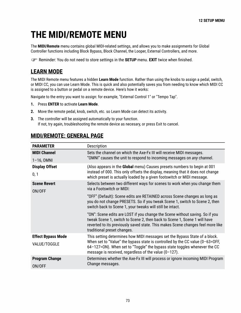
73
12 SETUP MENU
THE MIDI/REMOTE MENUThe MIDI/Remote menu contains global MIDI-related settings, and allows you to make assignments for Global Controller functions including Block Bypass, Block Channel, the Looper, External Controllers, and more.
Reminder: You do not need to store settings in the SETUP menu. EXIT twice when finished.
LEARN MODEThe MIDI Remote menu features a hidden Learn Mode function. Rather than using the knobs to assign a pedal, switch, or MIDI CC, you can use Learn Mode. This is quick and also potentially saves you from needing to know which MIDI CC is assigned to a button or pedal on a remote device. Here's how it works:
Navigate to the entry you want to assign: for example, "External Control 1" or "Tempo Tap".
1 . Press ENTER to activate Learn Mode.
2 . Move the remote pedal, knob, switch, etc. so Learn Mode can detect its activity.
3 . The controller will be assigned automatically to your function. If not, try again, troubleshooting the remote device as necesary, or press Exit to cancel.
MIDI/REMOTE: GENERAL PAGEPARAMETER DescriptionMIDI Channel
1–16, OMNI
Sets the channel on which the Axe-Fx III will receive MIDI messages. “OMNI” causes the unit to respond to incoming messages on any channel.
Display Offset
0, 1
(Also appears in the Global menu) Causes presets numbers to begin at 001 instead of 000. This only offsets the display, meaning that it does not change which preset is actually loaded by a given footswitch or MIDI message.
Scene Revert
ON/OFF
Selects between two different ways for scenes to work when you change them via a Footswitch or MIDI:
“OFF” (Default): Scene edits are RETAINED across Scene changes as long as you do not change PRESETS. So if you tweak Scene 1, switch to Scene 2, then switch back to Scene 1, your tweaks will still be intact.
“ON”: Scene edits are LOST if you change the Scene without saving. So if you tweak Scene 1, switch to Scene 2, then back to Scene 1, Scene 1 will have reverted to its previously saved state. This makes Scene changes feel more like traditional preset changes.
Effect Bypass Mode
VALUE/TOGGLE
This setting determines how MIDI messages set the Bypass State of a block.When set to “Value” the bypass state is controlled by the CC value (0–63=OFF, 64–127=ON). When set to “Toggle” the bypass state toggles whenever the CC message is received, regardless of the value (0–127).
Program Change
ON/OFF
Determines whether the Axe-Fx III will process or ignore incoming MIDI Program Change messages.

74
12 SETUP MENU
PARAMETER DescriptionIgnore Redundant PC
ON/OFF
This setting determines whether the Axe-Fx III should re-process or ignore a Program Change message that corresponding to the current preset. With this setting “OFF”, a preset will be reloaded—all changes discarded—when it is selected again via PC. This allows you, for instance, to load a preset, use various “Instant Access” switches to bypass effects, and then stomp the footswitch that originally selected the preset to have it revert to its saved state. With this setting “ON”, redundant PC messages are ignored. When PC mapping is used, if the current Scene has changed, the preset will not reload but the Scene will still revert to that set in the map.
Send MIDI PC
1–16 OMNI OFF
Determines whether or not the Axe-Fx III will automatically transmit a MIDI Program Change message at its MIDI OUT port when a new preset is loaded.
This is the easiest way for most people to operate a single connected MIDI device while changing presets on the Axe-Fx III. Any custom MIDI mapping is left to the downstream device. To use this feature you simply select which channel you want the message to be transmitted on. The “OMNI” setting transmits the message on all channels.
MIDI PC Offset Adds a specified value to all incoming MIDI Program Change requests before they are processed. This makes it possible, for instance, to address alternate presets in different “registers”. You might use the same MIDI messages to access presets 1–16 for a gig with one guitar, and —by specifying an offset of +16— use presets 17–32 for a different guitar without re-programming your controller.
PC Mapping PC Mapping determines whether incoming MIDI Program Change messages load presets 1-for-1, or load other presets and scenes instead. With PC Mapping turned “OFF”, presets are loaded 1:1 based on incoming MIDI bank Select and Program Change messages. With custom PC Mapping enabled, incoming Program Change messages are re-mapped according to the values in the table on the Custom page of the MIDI/Remote menu (see below).
INITIAL VALUE: External Control 1–16
These sixteen parameters specify the initial value to be used for each of the 16 External Controllers (p. 61) when the Axe-Fx III is powered on. This value persists until data is received from the MIDI controller. This is especially useful when an external MIDI controller is absent. For example, if you normally use an expression pedal to control the volume in your presets, a missing pedal might make the preset get “stuck” in a muted position. Setting an initial value of 100% for the External Controller mapped to that pedal would ensure that when the pedal is not connected, the volume will stay at 100% instead of 0%. This setting is only for controllers with a MIDI CC# assignment. It does not apply to local or FC pedals or switches.

75
12 SETUP MENU
MIDI/REMOTE: MAPPING PAGEWith PC Mapping enabled (see above), incoming Program Change messages are re-mapped according to the values in the table in this section.
PARAMETER DescriptionMap to Preset Map to Scene
When PC Mapping (above) is turned “ON”, the parameters in this table specify which preset and scene are loaded for each incoming MIDI PC message. See p. 47 for additional info on PC Mapping.
MIDI/REMOTE: BYPASS PAGEThe Bypass page of the MIDI menu allows you to map MIDI CC messages—or connected pedals and switches— to bypass or engage blocks. CC messages can be sent by a MIDI controller or computer connected to the MIDI IN jack, or via the USB connection of the Axe-Fx III. Each of these settings is global. In every case, the method for mapping a controller to one of these functions is the same:
1. Use the NAV knob to select the desired function. 2. Use the VALUE knob to assign a controller to the function:
� 1—127 to assign a MIDI CC#. � PEDAL 1 or PEDAL 2 to assign a pedal connected to the on-board expression jacks of the Axe-Fx III. � FC__ PEDAL 1–4 to assign a pedal connected to the corresponding pedal jack of the designated FC controller. � FC__ SW 1–4 to assign a switch connected to the corresponding switch jack of the designated FC controller. � NONE to remove all assignments from the selected item.
MIDI/REMOTE: CHANNEL PAGEThe Channel page works exactly like the Bypass page except the entries are used to set the Channel of each block instead of its bypass state. The value of the CC message sets the channel as follows:
0 = Channel A 1 = Channel B 2 = Channel C 3 = Channel D
The series continues, repeating A, B, C, D for values up to 127 (D). For additional information, see "Channel Select" on p. 46.
MIDI/REMOTE: EXTERNAL PAGEController assignments for the sixteen External Controllers used in Modifiers (See Section 9: Modifiers).
MIDI/REMOTE: LOOPER PAGEController assignments for the functions of the Looper.

76
12 SETUP MENU
MIDI/REMOTE: OTHER PAGEController assignments for various other functions of the Axe-Fx III.
PARAMETER DescriptionTempo Tap Provides the ability to tap the tempo using an external controller. Remember that
tempo is calculated using either the last two taps OR an average, as set in the global Tempo configuration (p. 63). Learn more about Tempo in Section 10.
Tuner Provides a way to remotely enter or exit the Tuner (Section 11).Preset Inc/Dec Preset Inc/Dec Start/Stop
These allow you to step up or down through a sequence of presets with pre-defined start and end/wrap points. Preset mapping and offsets are ignored.
Scene Select Selects specific Scenes. The controller value (NOT the CC number) determines which Scene is loaded:
0 = Scene 1 2 = Scene 3 4 = Scene 5 6 = Scene 7 1 = Scene 2 3 = Scene 4 5 = Scene 6 7 = Scene 8
The series continues, cycling through scenes 1–8 for values up to 127 (Scene 8).
For more, see "Scene Select" on p. 46 or "CC Value to Scene" on p. 102Scene Increment Scene Decrement
The Scene Increment and Decrement functions allow you to step up or down through scenes. These functions are triggered by CC data values above 63.
Input 1,2,3,4 Volume Output 1,2,3,4 Volume
Eight individual parameters allow you to globally control the levels of the corresponding Input or Output blocks.
Output 1 Volume Increment, Output 1 Volume Decrement, Output 2 Volume Increment, Output 3 Volume Decrement
These options provide a convenient way to permanently increase or decrease the MAIN output volume for the Out 1 or Out 2 Blocks in the currently loaded preset. Each time Volume Increment is triggered, the MAIN is increased by 1.0 dB and the preset is saved. This is the same for Volume Decrement, except it decreases volume.
IMPORTANT! Any unsaved changes such as altered effect parameters or bypass states will also be stored when either of these functions is triggered!
These functions are designed for use with momentary footswitches set up to send a CC# value of 127 for “ON” and 0 for “OFF”. Do not use an expression pedal or you could inadvertently increase levels to +20 dB with a single sweep!

77
12 SETUP MENU
THE UTILITIES MENUUTILITY: DISPLAY PAGEProvides a slider to adjust contrast/viewing angle for the built-in LCD display.
UTILITY: ADC LEVELSShows Analog-to-Digital Converter levels for the four front panel Level knobs and rear panel Expression jacks for troubleshooting. You can set the output level here at an exact percentage.
UTILITY: RESET PAGEThis page provides a tool to set parameters in the SETUP menu back to factory default values. Reset system parameters is one of the first steps of troubleshooting. It never deletes or modifies your presets. You will be prompted to press ENTER to confirm.
Be very careful with this option . Resetting system parameters is irreversible!
A second utility provides the ability to Clear all Presets . You will be prompted to press ENTER to confirm.
Be very careful with this option . Erasing presets is irreversible!
UTILITY: USB PAGEThis page meters the USB input and output FIFO buffers. Ideally these will be at around 50%. If the buffer overflows or underflows, USB Buffer Size (p. 70) should be increased. Remember that you need to quit all audio applications or remove and reconnect the USB cable to reset the buffer.
UTILITY: FIRMWARE PAGE This page indicates which firmware version the Axe-Fx III is running.
USB and FPGA firmware versions are also shown.
For more information, see "Tap Tempo" on p. 68.

78
13 FC CONTROLLERS
The Fractal Audio FC-6 and FC-12 foot controllers are designed for use with the Axe-Fx III and other Fractal Audio products. Every FC offers an impressive suite of features and capabilities, incorporating years of innovation and customer feedback. They look great too, making an awesome addition to your stage or studio.
All aspects of the FC are set up through the Axe-Fx III under SETUP: FC Controllers (p. 67).
The FC has its own Owner’s Manual available from http://fractalaudio.com/fcm
The Fractal Audio Footswitch Functions Guide covers additional details. Find it at https://www.fractalaudio.com/fas-ffg
13 FC CONTROLLERS

79
14 IR CAPTURE
This section details the use of a built-in tool that allows you to capture you own Impulse Responses using the Axe-Fx III and some additional equipment.
Whether part of a combo or housed in its own cabinet, the speaker is a major part of the sound of any guitar or bass amp. When you hear great tone on a recording or at a live show, this means someone somewhere has done a great job of selecting and placing mics (even if the player is already using a Fractal Audio product!).
The Axe-Fx III uses Impulse Responses (“IRs”) to faithfully reproduce the sound of a mic’d speaker, with over 2,048 Factory Cabs provided, and 2,048 more memory slots for User Cabs. Our store offers many professionally produced Cab Packs, but you can also create your own IRs using the IR Capture utility in the Axe-Fx III. The process is easy and requires only some common pro-audio gear.
Learn more about Impulse Responses in the Cab Block section of “The Fractal Audio Blocks Guide”
DECIDE ON A CAPTURE METHODThere are two different methods of IR capture. Both methods require microphone(s) and preamp(s), and both methods produce excellent results.
Method 1 requires a flat, neutral, full-range power amp. This will typically be a solid-state amp designed for pro-audio applications (e.g. not a guitar-oriented amp, which would add tonal coloration).
Method 2 adds a speaker-level DI box — such as the Fractal Audio X-Load LB-2 — to “factor out” the power amp, so you can use any amp—even a regular guitar amp.
MONITOR YOUR AXE-FX IIIWhen creating IRs, you’ll probably want to test-drive the results right away. Connect your guitar to your Axe-Fx III and set up whatever you’d normally use for direct, full-range monitoring (headphones, studio monitors, powered FRFR speakers, etc.). The capture process uses OUTPUT 2 LEFT, so please ensure that Output 2 | Copy Output 1 is set to “OFF” on the Audio page of the I/O menu under SETUP.
MIC THE SPEAKER � Before you can mic a speaker, you’ll need to play through it. You can plug right in to the actual guitar amp
itself as you normally would, or you can use an Axe-Fx preset (with the Cab block bypassed or circumvented) into a neutral power amp, into the speaker. One advantage of the latter method is that once you capture the IR, you can use the same exact amp for testing, which should produce results remarkably close to the original.
� Once you’ve got a good guitar tone coming through the speaker, it is time to set up the mic(s). Recording studios have control rooms isolated from the “live room”, making it easy to hear what the microphone is picking up without interference from a loud amp. Having an assistant or robot to adjust the mic is convenient. If this option isn’t available to you, try using headphones to let you focus on the mic’d tone. It might be loud, so take care not to damage your hearing.1 You can also record the amp and listen back to make sure you are satisfied with the tone.
1 https://www.osha.gov/SLTC/noisehearingconservation/
14 IR CAPTURE

80
14 IR CAPTURE
� The tone you get from a mic’d speaker depends on the type(s) and position(s) of the microphone(s). Select a mic that is well-suited for guitar cab recording and position it according to your preference. Information is widely available about mic placement, distance, angle, etc., but don’t be afraid to experiment.
� Each mic needs to be connected to a preamp to bring the signal up to line level for processing. The preamp also contributes to the tone, so a high-quality preamp (like an API or Neve) is generally preferred, but even an inexpensive mixer can produce excellent results. Don’t allow the mic preamp to distort.
� With an optional mixer, you can combine multiple microphones to capture a blend. � EQ is OK, but dynamics processign such as compression can cause the IR to misrepresent the source. � If the cab is loaded with multiple speakers, you should listen to each one to see how they compare.
SETUP 1: MIC ONLYMethod 1 (“MIC ONLY”) requires a microphone, a preamp, and a flat, neutral power amp.
� Set up a preset with your preferred Amp block, and set its Cab block to “SCRATCHPAD 1” for instant auditioning. � Connect the mic to the input of the preamp. � Connect the output of the preamp (or mixer) to INPUT 2 LEFT of the Axe-Fx III. � Connect OUTPUT 2 LEFT of the Axe-Fx III to the input of your power amp. � Connect the power amp’s speaker out to your speaker. � Open the Config page of the IR Capture Utility under SETUP and set Capture Method to MIC ONLY. � Follow the Capture Instructions on p. 82
Spkr. Input
Amp Sp kr. Out
MICPRE
POWER AMP
SPEAKER
MIC
Mic In
Line Out
IN 2 L OUT 2 L
Amp Input
NOTE: IRs created using this method will include any tonal coloration imparted by the power amp. Cab-Lab can remove this effect using a separate “Reference IR” of just the power amp created using a speaker-level to line-level DI, but if you have this DI-box at the time of capture you might as well use “Mic + DI” (next page).

81
14 IR CAPTURE
SETUP 2: MIC + DIMethod two requires a microphone, a preamp, and a DI Box with the special capability to convert speaker level to line level. This method has an advantage in that it “factors out” the tonal Influence of the power amp, allowing almost any amp to be used. A neutral power amp is still preferrable, but even a regular guitar amp can produce excellent results, as the Axe-Fx is able to remove distortion, completely separate the speaker response, and produce a pure and accurate IR.
� Connect the mic to the input of the preamp.
� Connect the output of the preamp to the IN 2 Left of the Axe-Fx.
� Connect Out 2 Left of the Axe-Fx to the FX Return of your guitar amp. If your amp doesn’t have an FX return, use the guitar input. Set the amp to as clean a setting as possible.
� Connect the amplifier’s speaker out to the speaker level input of the DI box. Be sure to use a DI box that is specifically designed to work with speaker level signals and one that does NOT have any on-board cabinet emulation. You can also use a DI output on your amp if it has one, as long as it is NOT a speaker emulated output.
� Connect the Speaker Out or Thru jack of the DI box to the input of your speaker.
� Connect the Line Level Output of the DI box to IN 2 Right of the Axe-Fx.
� Open the Config page of the IR Capture Utility under SETUP and set Capture Method to MIC + DI.
� Open the Audio page of SETUP: I/O and ensure that INPUT 2 MODE is set to “STEREO”.
� Follow the Capture Instructions on p. 82
MICPRE SPEAKER
LEVELDI BOX
SPEAKER
MIC
Mic Pre Line Out
Mic Pre In
Speaker ThruSpeaker In .
Amp Speaker Out
Speaker In
IN 2 L IN 2 R OUT 2 L
D.I. Line Out
GUITAR AMP(or any power amp)
To Amp Inputor FX Return

82
14 IR CAPTURE
CAPTURING IMPULSE RESPONSESUSING AXE-EDIT OR CAB LABAxe-Edit now includes a free IR Capture Utility which serves to control for the Axe-Fx III during IR capture.
Cab-Lab is an IR Mixer and Toolbox, available at https://www.fractalaudio.com/cab-lab-3. It is strongly recommended that you use Cab-Lab to capture IRs. The interface is easier to use, and you will also be able to save the raw IR data to your computer for later remixing or re-processing.
FROM THE AXE-FX III FRONT PANELThis section covers capturing from the Axe-Fx III front panel:
1. Make the connections for your chosen setup as detailed on the previous pages of this section.
2. In the Axe-Fx III, create a preset with an Amp block set to an appropriate model and a Cab block with Cab 1 set to Bank: “SCRATCHPAD”, Number: “1”. In that same Cab block, set Cabs 2, 3 and 4 to “MUTED”. IRs are automatically sent to this special location upon capture for instant auditioning.
3. Open SETUP, NAV to the IR Capture menu, and press ENTER.
4. On the Config page, you will typically want Capture Mode set to “ULTRA-RES”, though “STANDARD” resolution is also available. Capture Method should be set to “MIC ONLY” or “MIC+DI” depending on which setup you are using.
5. On the Config page of the IR Capture utility, select a Bank and a Slot where you want the finished IR to be saved. Enter a Name using the functions on the B,C, D and E knobs.
6. On the Config page, consider the following optional parameters as well:
� Deconvolution: In low-noise environments the conventional technique can provide slightly better bandwidth and magnitude accuracy. In a higher-noise environment the reverse filter technique can provide better results.
� IR Processing: This selects between “Minimum-Phase” which transforms the IR into a minimum-phase version, “Auto-Trim” which removes the leading silence, and “None” which applies no processing at all.
� Delay Compensation: This allows compensating for excessive delays due to extreme mixer latency or far-field mic distances. To use the compensation refer to the graph on the Capture page. Press E to select “Graph (Time) and do a test sweep. Note the waveform delay and dial in the desired amount of compensation. Note that the speed of sound is roughly 1 ft/ms so a mic that is 10 ft from the speaker would incur roughly 10 ms of delay. Note that IR Capture Utility will automatically compensate for delays up to approximately 20 ms (1K samples). Correction is only required for delays greater than 20 ms.

83
14 IR CAPTURE
7. Press the TEST button (Push-knob A) to generate a test sweep for setting levels.
8. The OUTPUT LEVEL 2 knob on the front of the Axe-Fx III sets the level of the sweep signals sent to the power amp. Turn it — and your power amp — up until you hear the test through the speaker. It should be loud enough to push the speaker to “optimal” levels and eliminate background noise interference, but not loud enough to be uncomfortable or cause distortion.
9. The front panel INPUT 2 LED meter of the Axe-Fx III indicates the signal level coming back to the Axe-Fx III from the mic and preamp or mixer. Adjust the preamp output levels and use INPUT 2 level on the Input page of the I/O menu to ensure that the signal is nice and hot without clipping. It is OK to “tickle the red” LED, as this indicates a level of -6 dB, below actual clipping.
10. Once levels are set correctly, it is time to capture. Press the on-screen CAPTURE button (Push-knob B) and wait quietly for the capture to complete (two sweeps, ~5 seconds).
11. If you set up the test preset in Step 2 correctly, you should hear the IR automatically and be able to audition it at once.
12. Press SAVE to store your capture to the location you selected in Step 5.
13. Be sure to select a new location and name before performing any additional captures with the same setup.

84
14 IR CAPTURE

85
15 ADDITIONAL TOPICS
FRACTAL-BOTFractal-Bot is required for Backing up and Restoring sounds and settings (below), Updating Firmware (p. 86) and can be used for Transmitting Presets, or Installing User Cabs (p. 92).
The program is self-explanatory and has instructions built in.
To be able to use Fractal-Bot, Windows users will need to install a driver to enable communication between the computer and the Axe-Fx III. The Windows driver is available at https://www.fractalaudio.com/axe-fx-iii-downloads.
Computers running OS X do not require a driver to communicate with the Axe-Fx III.
Download and install Fractal-Bot from our web site at http://fractalaudio.com/fractal-bot.php.
15 ADDITIONAL TOPICS
BACKING UP & RESTORINGOnce Fractal-Bot is installed, you can use it for backing up or restoring or installing files.
BACKING UPFractal-Bot automates the backup process. Select the RECEIVE tab and follow the built-in instructions. Here are some things to consider when using Fractal-Bot:
� The Axe-Fx III doesn’t emphasize this distinction, but its Presets are actually divided into banks of 128. To backup all of your presets, backup all of the banks: A (0–127), B (128-255), C (265–383) and D (384–511).
� A backup of the SYSTEM includes all of the custom settings in the Setup menu: Global, I/O, MIDI/Remote, and Tuner settings.
� User Cabs are backed up in two individual banks.
� In Fractal-Bot, you will need to specify a location for the backup files. It is wise to prepare this in advance. Many pros we work with use a consistent naming system for their backup folders: “yymmdd - Axe-Fx III” (two digit year, two digit month, two digit day). In addition to the backup files, create a text file to remind you what firmware version was installed when the files were created.
RESTORINGFractal-Bot is also used to restore backup files to your Axe-Fx III. In this case, the process is less automated but still very easy. You will need to send over all of the files from your backup set individually. Once the first file completes, send the next file over, and so on, until they are all finished. Remember to reboot the Axe-Fx III immediately if a System file has been transmitted to it! (Fractal-Bot will remind you.)
You can use the same process to install presets or cab files you download.
MIDIOn the Axe-Fx III, backup and dumping are not supported over 5-pin MIDI. You can transmit backup files to the unit this way, but because the transfer rate is so slow, this can take a LONG time and is advised against.
86
15 ADDITIONAL TOPICS
FIRMWARE UPDATESOur products are upgradeable, and we are committed to continual improvement. These highly antipated updates add new amps, cabs, effects and features, fix issues, and more. We recommend keeping the firmware in your Axe-Fx III up to date as new versions are released. Firmware is technically software — the “operating system” of your Axe-Fx III — tracked using version numbers: 1.00, 1.01, 2.00, etc. Every Axe-Fx III is shipped from the factory with the latest version installed. You can check your version any time by pressing the SETUP button (Push-knob E) on the Home page. The version is displayed at the top left of the Setup menu.
UPDATINGUpdating is safe, easy, and quick with Fractal-Bot (see previous page). Before you begin, please QUIT any other applications which might interfere, including Axe-Edit and any DAW software or audio/MIDI applications.
1 . Download the latest firmware for your Axe-Fx III from https://www.fractalaudio.com/axe-fx-iii-downloads.2 . Unzip the download file. The archive may contain various documents in addition to the actual firmware file,
which is a MIDI System Exclusive or “SysEx” file. Extract the .syx file to a location you can easily find when required. Do not double‑click the .syx file. Fractal-Bot will prompt you for its location when it is needed.
3 . Please read the Release Notes included with the firmware download. They’ll let you know what’s new and alert you to anything you may need to be aware of before updating to the new version.
4 . Before performing a major firmware update, it is not unwise to back up your Axe-Fx III (see previous page).5 . Launch Fractal-Bot and proceed through three self-explanatory steps. 6 . Firmware updates will occasionally be accompanied by new versions of the Axe-Fx III Factory Presets. These
will be available on our web site support page and can also be installed using Fractal-Bot.
FIRMWARE Q&A: Q How do I know the upgrade worked?: A Check your firmware version anytime by pressing the SETUP button (Push-knob E)
on the Home page. The version is displayed at the top of the Setup menu.
: Q Can I skip versions to go from a very old firmware version to a much newer one?: A You can upgrade from any version to any other version. When you skip versions it is recommended that you
also read the Release Notes for all interim versions, all of which are included with every firmware release.
: Q Will updating my firmware erase, modify or “upgrade” my factory presets?: A Firmware updates do not erase customized presets. However, firmware updates may
alter the sound of existing presets. Always read Release Notes before updating. Saving presets after a firmware update can render them incompatible with previous versions. It is always wise to create a full back up using Fractal-Bot before a major update.
Firmware updates do not upgrade Factory Presets. Updated Factory Presets, when offered, are released as a separate update on our web site support page. Fractal-Bot can be used to transmit this update in the same way it is used to update firmware.
: Q The firmware update failed mysteriously. What should I do?: A If the Axe-Fx still boots normally, just try the update again. If successive failures occur, please delete and
re-download the update file before trying again. Trying a different USB port or cable can also solve issues.
: Q After updating, my Axe-Fx will no longer boot normally.: A See “Recovery” on the next page.

87
15 ADDITIONAL TOPICS
RECOVERYPROBLEMS DURING/AFTER FIRMWARE UPDATEThe Axe-Fx III has a built-in recovery system known as the “Emergency Boot Loader” to protect you against mishaps during firmware update. To boot from the emergency boot loader:
1. Power down the unit and wait five seconds.2. Power on holding both PAGE LEFT and PAGE RIGHT buttons until the Emergency Utility page appears.3. Update as normal using Fractal-Bot.
PROBLEMS WITH A SINGLE PRESETIf your Axe-Fx III will not boot normally, the problem may just be the current preset. You can force the unit to load an empty initialized preset as follows:
4. Power down the unit and wait five seconds.5. Power on holding HOME until the boot-up progress bar first appears.
The Axe-Fx III will boot with an empty initialized preset in location “000”. You can STORE this to any other location to overwrite a problematic preset.
PROBLEMS WITH GLOBAL SETTINGS OR PARAMETERSIn the very unlikely event that a problematic system parameter prevents the Axe-Fx III from booting normally, you may use the following procedure to recover:
1. Power down the unit and wait five seconds.2. Power on holding EDIT until the boot-up progress bar first appears.3. Enter SETUP, open the Utilities menu, and page to Reset .4. Execute Reset System Parameters as indicated on-screen (Push-knob A followed by ENTER).
WARNING! Do NOT accidentally perform CLEAR ALL PRESETS!!!5. Follow the on-screen instructions to execute. Press HOME when finished.
You can in fact hold both HOME and EDIT at once to reset the current preset and prevent the loading of global settings and parameters.
GETTING HELPOur forum is a source of great help ranging from product Q&A to tutorials and more. Fractal Audio staff participate in the conversation, and response times can be very fast. Find it at https://forum.fractalaudio.com.
Our wiki, maintained by members of the Fractal Audio community, is also an excellent resource: https://wiki.fractalaudio.com.
You can get support directly from Fractal Audio Systems at: https://support.fractalaudio.com or internationally via our dealers listed at https://www.fractalaudio.com/international-ordering.

88
15 ADDITIONAL TOPICS
GLOBAL BLOCKSGlobal Blocks provide a convenient way to synchronize parameter changes across multiple presets.
If you use multiple presets and want to keep certain sound settings the same in all of them, you might imagine needing to repeat those changes into every preset, one by one. Another idea might be to use Axe-Edit to copy/paste the desired blocks from one preset to another. Global Blocks eliminate these the need for such tedious, repetitive tasks. Any change to any Global Block in one preset is made automatically across all other presets where that Global Block is used.
Each block type that supports Global Blocks is backed with eight Global Blocks of its own. For example, there are eight DIFFERENT Global “Amp 1” blocks and an additional eight DIFFERENT Global “Amp 2” blocks. Global blocks are stored outside the preset area in “System Memory.” All parameters in all channels can be governed by Global Blocks. All modifiers, however are stored in the preset itself and are NOT part of the Global Block.
GLOBAL BLOCKS SUPPORTMost of the 40+ block types support the use of global blocks. (The following are NOT included: Crossover, FB Send/Return, IR Player, Looper, Megatap, MIDI, Mixer, Multiband Comp, Multiplexer, RTA, Resonator, Synth, 10-tap delay, Vocoder.)
GLOBAL BLOCKS EXAMPLEImagine a set of five different presets used for a live rig. Each of them has one amp block (AMP 1) with the same settings, but this amp is surrounded by totally different effect chains. Now, depending on the venue, your guitar, the backing band, the audience, the weather, you name it... You may want to make changes to your amp block, just as you would any physical amp. Turn up the treble. Turn down the gain. Adjust the Graphic EQ. Using the simple operations described on the next page, it becomes easy to link the amp blocks in these presets together, so modifying any one of them changes all of them.
First, you would open one of the presets where the amp is dialed in nicely. Now, save that Amp’s settings as a Global Block by selecting Amp 1 and choosing LINK TO GLOBAL BLOCK. Let’s say we choose “Global Block 1”. Don’t forget to save the preset!
Now, open each of the remaining presets, select AMP 1, and choose LINK TO AND LOAD FROM GLOBAL BLOCK, selecting “Global Block 1”. The settings from Amp 1: Global Block 1 appear automatically, and the link is created. Don’t forget to save the preset! Repeat as needed for other presets.
Other applications for Global Blocks include using them to change gate threshold settings as you change from an active guitar or bass to a passive one, globally adjusting the level of a volume block used as a “boost”, dialing in individual effects that are used with different amps in different presets, and much more.

89
15 ADDITIONAL TOPICS
Global Block OperationsFour different operations enable presets to interact with Global Blocks. You can find these operations on the Tools page of the Layout menu (from the Grid, page right to “Tools”). To execute a function, select the desired grid block using the NAV buttons, use the VALUE wheel to choose the desired Global Block function, turning the E knob if indicated to select the desired Global Block number, and press ENTER or the “Execute” button (Push-knob C).
Using Axe-Edit makes working with Global Blocks even easier, and also provides a high level view of where they are used in your preset.
LINK TO GLOBAL BLOCKThe Link to Global Block function “creates” a Global Block from a block in your preset, and then creates a link between the two. This is always the first step when you want to begin using Global Blocks. Any existing settings in the selected Global Block is over-written with the settings from the block in your preset. After a link is created, any time you save changes, the Global Block is updated. Any time another linked preset is changed and saved, this preset will be updated.
Always save your preset immediately after creating a link to a Global Block.
LOAD FROM AND LINK TO GLOBAL BLOCKThe Load from and Link to Global Block function loads existing Global Block data into the selected block in your preset, and then creates a link between the two. You would normally use this function to link a set of presets to a Global Block that you first created using the Link to Global Block function (above). After a link is created, any time you save changes, the Global Block is updated. Any time another linked preset is changed and saved, this preset will be updated.
Again, always save your preset immediately after creating a link to a Global Block!
LOAD FROM GLOBAL BLOCKThe Load from Global Block function loads existing Global Block data into the selected block in your preset, but does NOT create a link between the two. This allows you to use Global Block data as a “template” for populating local block settings without the usual link.
UNLINK FROM GLOBAL BLOCKThis operation totally disconnects the selected block from any Global Blocks.
UNLINK ALL BLOCKS FROM GLOBALThis operation unlinks all blocks in the current preset from Global blocks to which they may be linked.

90
15 ADDITIONAL TOPICS
PERFORMANCE CONTROL PAGESINTRODUCTIONThe two Performance Control pages of the Axe-Fx III provide a way for you to design and build your own custom front panel menu pages, each with your choice of any ten knobs, switches, or parameters from any block. Performance Control pages eliminate the need for menu-diving to find the controls for your favorite settings. The ten on-screen knobs map directly to the front panel A, B, C, D, and E knobs of the Axe-Fx III. This creates an experience very much like using a traditional amp or pedal where what what you see is what you get.
One of the Performance Control pages is “Global” meaning that the 10 parameters you place there remain the same even as you change presets. The values of these controls change — for instance, if you place AMP 1/TREBLE, you will see the Treble setting change from say, 6, to 3 to 10 as you switch presets, but the AMP 1/TREBLE knob itself will always appear in the same place on the Global Performance Control page. Meanwhile, the “Per Preset” Performance Control page allows you to choose up to ten different parameters in each and every preset. One preset might show ten Amp controls, while the next shows ten effect controls, while the next shows a mix of both. Each parameter on the page shows a 2-line text label. By default, these show the block name/number, and the parameter name, but you can change these to custom values.
The two Performance Control pages are located in the HOME menu of the Axe-Fx III. Press HOME, then PAGE to either Per-Preset (“Perform-PP”) or Global (“Perform-Gbl”) tabs. Use the NAV buttons to switch between the controls. Use the A,B,C,D or E knobs or VALUE to make changes. Because these pages are designed for use during a performance, the Axe-Fx III will not leave them if you change presets or scenes.
In summary, Performance Control pages represent a powerful way to design the perfect setup for quick changes, such as during a soundcheck, or even (gasp) in the middle of a solo.
Axe-Fx III
025: My Rig Preset Scene: 2
TUNER LAYOUT CONTROLLERS AMP 1 AMP 2
AMP1Input Drive
AMP1Presence
Delay 1Time
Delay 1Mix
Reverb 1Mix
In 1Threshold
AMP1Mid
AMP1Bass
AMP1Treble
AMP1Level
Home Perform-PP Perform-Gbl
4.98
A Sample Performance Control Page, showing a mix of Amp and Effect Controls

91
15 ADDITIONAL TOPICS
PLACING CONTROLS ON PERFORMANCE PAGES Performance Pages must be set up using Axe-Edit, the companion editor/librarian software for the Axe-Fx III. In the following tutorial, we will set up a few examples.
1. Decide whether you want to set up the Global page or the Per Preset page. Remember: parameters placed on the global page stay there as you change presets. Those on the Per-Preset page will be different from one preset to another. The Global Page might contain your top ten “go to” parameters. Many players will place the basic knobs of the AMP 1 block here: Drive, Bass, Mid, Treble, Presence, Depth, Master Volume, Level, etc. Let’s get started with this in our tutorial.
2. Connect your Axe-Fx III over USB to a compatible Mac or Windows computer. You will need a driver if you are running Windows. See Chapter X.
3. Install and Launch Axe-Edit III. Learn more about Axe-Edit on p. X.
4. To add Amp 1 controls to the Global Performance Control page, we need to begin in a preset containing the Amp 1 block. Click the PRESETS button in Axe-Edit, then click the preset of your choice: 008: Plexi 50W for example.
5. On the grid, click the AMP 1 block. Change the “Authentic” tab if it isn’t already selected.
6. Switch to the Performance Control editor by clicking the Perform button above the grid.
7. Drag and Drop the Input Drive parameter by its label to the first slot of the Global Performance Controls. IMPORTANT: You must drag controls by their LABEL! If you drag on the knob, you will change its value. Don’t panic if this happens, just UNDO by pressing Command + Z (Mac) / Control + Z (Win).
8. Continue drag-and-drop of parameters to desired locations. You can in fact drag ANY parameter from anywhere in any block. You are limited to ten, and you don’t need to fill all of the slots. TIP: You do not need to exit the Performance Control editor to change blocks... use the shortcut menu found to the left of the large block icon in Axe-Edit. It lists every block in the current preset.
9. You can use drag-and-drop to rearrange controls in Axe-Edit. To remove any control, select it and press Delete/Backspace on your keyboard.
10. You can change the label for any control by double-clicking on the existing name. Type your desired text and then press Enter/Return on your keyboard to confirm.
11. Since we are setting up the Global Performance Controls, there is no need to save. When working with Per-Preset Performance Controls, however, you must save the preset after you finish drag-and-drop.
12. Check your work on the Axe-Fx III. Press HOME and then page to the Perform-Gbl tab.
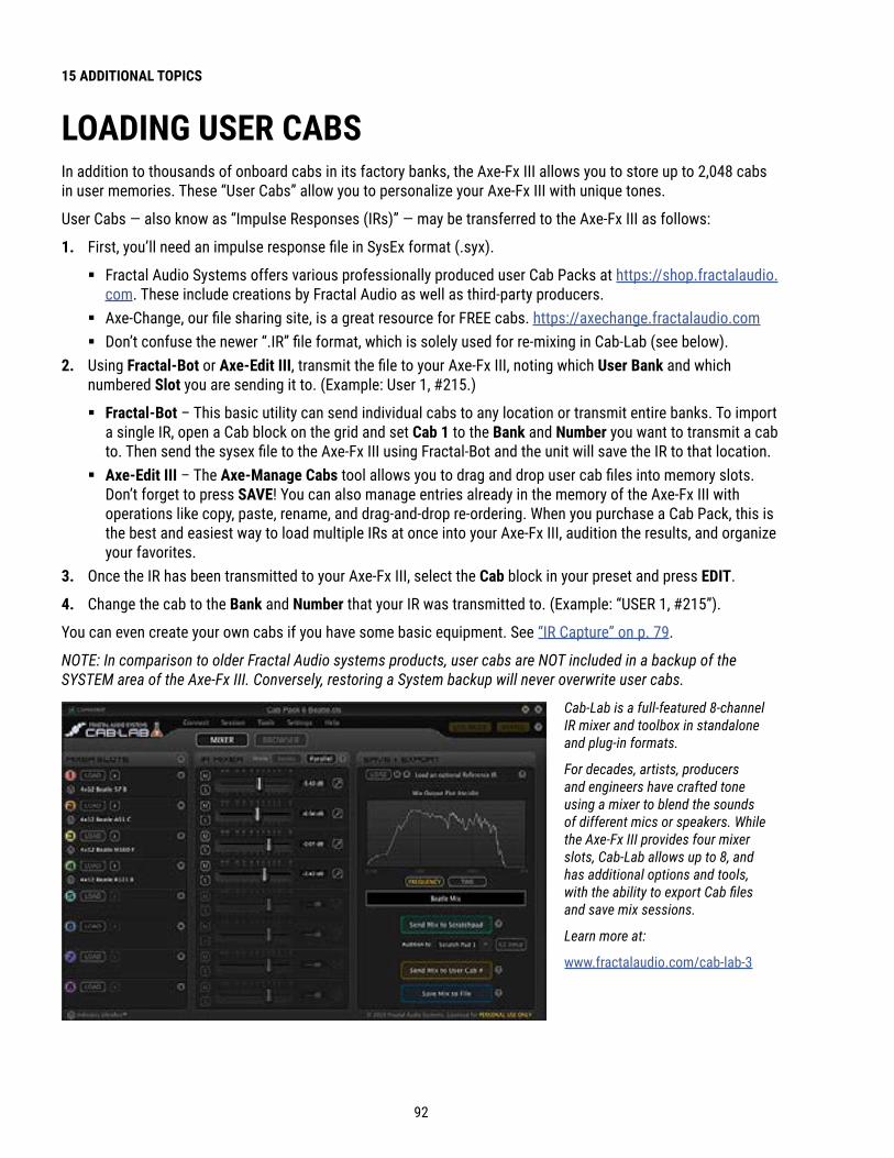
92
15 ADDITIONAL TOPICS
LOADING USER CABSIn addition to thousands of onboard cabs in its factory banks, the Axe-Fx III allows you to store up to 2,048 cabs in user memories. These “User Cabs” allow you to personalize your Axe-Fx III with unique tones.
User Cabs — also know as “Impulse Responses (IRs)” — may be transferred to the Axe-Fx III as follows:
1 . First, you’ll need an impulse response file in SysEx format (.syx).
� Fractal Audio Systems offers various professionally produced user Cab Packs at https://shop.fractalaudio.com. These include creations by Fractal Audio as well as third-party producers.
� Axe-Change, our file sharing site, is a great resource for FREE cabs. https://axechange.fractalaudio.com � Don’t confuse the newer “.IR” file format, which is solely used for re-mixing in Cab-Lab (see below).
2 . Using Fractal-Bot or Axe-Edit III, transmit the file to your Axe-Fx III, noting which User Bank and which numbered Slot you are sending it to. (Example: User 1, #215.)
� Fractal-Bot – This basic utility can send individual cabs to any location or transmit entire banks. To import a single IR, open a Cab block on the grid and set Cab 1 to the Bank and Number you want to transmit a cab to. Then send the sysex file to the Axe-Fx III using Fractal-Bot and the unit will save the IR to that location.
� Axe-Edit III – The Axe-Manage Cabs tool allows you to drag and drop user cab files into memory slots. Don’t forget to press SAVE! You can also manage entries already in the memory of the Axe-Fx III with operations like copy, paste, rename, and drag-and-drop re-ordering. When you purchase a Cab Pack, this is the best and easiest way to load multiple IRs at once into your Axe-Fx III, audition the results, and organize your favorites.
3 . Once the IR has been transmitted to your Axe-Fx III, select the Cab block in your preset and press EDIT.
4 . Change the cab to the Bank and Number that your IR was transmitted to. (Example: “USER 1, #215”).
You can even create your own cabs if you have some basic equipment. See “IR Capture” on p. 79.
NOTE: In comparison to older Fractal Audio systems products, user cabs are NOT included in a backup of the SYSTEM area of the Axe-Fx III. Conversely, restoring a System backup will never overwrite user cabs.
Cab-Lab is a full-featured 8-channel IR mixer and toolbox in standalone and plug-in formats.
For decades, artists, producers and engineers have crafted tone using a mixer to blend the sounds of different mics or speakers. While the Axe-Fx III provides four mixer slots, Cab-Lab allows up to 8, and has additional options and tools, with the ability to export Cab files and save mix sessions.
Learn more at:
www.fractalaudio.com/cab-lab-3

93
15 ADDITIONAL TOPICS
AXE-CHANGEAxe-Change is the official source for sharing Preset and Cab files for your Axe-Fx III and other Fractal Audio Systems products. You can upload your own creations or browse what others have contributed including some high profile artists (though regrettably many artists treat their Axe-Fx presets as guarded secrets).
Find Axe-Change at https://axechange.fractalaudio.com.

94
15 ADDITIONAL TOPICS
SHORTCUTSThe Axe-Fx III has several shortcuts and hidden features. These are summarized below.
IN GENERAL � To show the Layout Grid for the current preset, push the VALUE wheel.
� Press EDIT to jump to the Edit menu for the currently selected block.
ON THE HOME PAGE � Press ENTER to show the Layout Grid for the current preset.
� Use NAV LEFT/RIGHT to select presets and press NAV UP/DOWN or turn knob A to select scenes.
� Press Push-knob A to jump to the Edit menu of the AMP 1 block.
IN THE AMP BLOCK � On the Output EQ page, press ENTER to flatten the EQ.
� On the Output EQ page, press NAV UP/DOWN to change the number of bands.
IN THE CAB BLOCK � NAV to the Cab Number field and press ENTER to enter the Cab Picker for the selected.
ON THE GRID � With any block selected, press-and-hold ENTER to create a series of shunts and cables to bridge
empty space to the right. This will also CLEAR existing connectors between a series of blocks.
IN THE EDIT MENU OF ANY BLOCK � Press EDIT to skip to the Edit menu of the next block, or multiple times to step through all blocks.
TO OPEN THE CONTROLLERS MENU � Press the TEMPO button once.
ON THE SEQUENCER PAGE OF THE CONTROLLERS MENU � With any Stage selected, press ENTER to randomize the values of all stages.
95
15 ADDITIONAL TOPICS
SPILLOVERSpillover allows delay and reverb tails to “ring out” when an effect is bypassed or when you change channels, scenes, or presets. This section covers how to set up spillover in different scenarios.
WHEN BYPASSING A BLOCK (“IA” SWITCHES) . . .Block spillover is easy and requires only a particular setting in the block. For tails to ring out when an individual block is bypassed, set that block’s Bypass Mode to “MUTE FX IN”. If an effect is running in parallel, use “MUTE IN” instead. Be aware that different channels share effect memory, so changes to time, size, etc, may cause a “sweep” in the tail.
WHEN SWITCHING SCENES . . .Switching Scenes provides one of the best ways for sound changes to have perfect spillover. Since Scenes simply bypass or engage blocks one-by-one or in groups, just refer to the instructions above for all blocks in your preset.
WHEN CHANGING PRESETS . . .Spillover across different presets is a bit more involved. The first step is to open the Settings page of the Global menu under SETUP and set the Spillover parameter to determine whether “DELAY”, “REVERB”, or “BOTH” will spill over when you change presets.
You must also ensure that the exact same Delay or Reverb blocks exist in each of them. These need to be the same block and the same number (i.e. Delay 1 spills over only through Delay 1, Delay 2 through Delay 2, etc.).
For spillover to work perfectly, the pair(s) of blocks in both “starting” and “landing” presets must have similar settings and placement on the grid. The moment you change to a new preset, the parameter settings for its blocks will “take over” the duties of processing any tails. So, for example, if you change from a preset where Delay 1 has a time of 500 ms to one where the same value is 100 ms, the tails will suddenly be heard as 100 ms echoes instead. You would likewise hear quite a sudden difference in the tail, for instance, if a delay were placed after a clean amp block in one preset, and before an overdriven amp block in another! Bypass states and Bypass Mode settings must also be considered.
For a simple preset spillover experiment, create a preset, then save an exact copy to a new location and test spillover. Then begin making changes as needed to settings outside of those blocks that you want to spill over. Axe-Edit III also makes it easy to copy and paste a block from one preset to another.

96
15 ADDITIONAL TOPICS
SENDING MIDIMIDI Messages are transmitted at the MIDI OUT/THRU port of the Axe-Fx III. Connect a 5-pin MIDI cable from the MIDI Out to the MIDI In of your other device.
SEND MIDI PCThe simplest MIDI capability of the Axe-Fx III is transmitting a single MIDI program change message (“PC”) each time a new Preset is loaded—whether via the front panel, using an FC Footswitch, or in any other way. To enable this, open the SETUP | MIDI/Remote menu and page to the “General” tab. Set Send MIDI PC to the desired MIDI channel.
THE SCENE MIDI BLOCKA more sophisticated MIDI tool is the Scene MIDI Block. Once you place this block on the grid, it transmits MIDI messages automatically whenever a new scene is loaded—whether via the front panel, with a footswitch, or by any other means. The Scene MIDI block can transmit up to eight total custom PC or CC messages. Remember that a “default scene” loads automatically when you select a new preset, so any footswitch that selects a new Preset or a new Scene can also cause the Axe-Fx III to send a burst of MIDI messages. See the “The Fractal Audio Blocks Guide” for more on the Scene MIDI Block.
CONTROL SWITCH MIDIAnother way the Axe-Fx III can transmit MIDI messages is using Control Switches set up on an external Fractal Audio FC-6 or FC-12 Controller. The primary function of a Control Switch is to operate as a Modifier source to control sound parameters. Beyond this, however, each of the six Control Switches has the capability to transmit a custom “payload” of MIDI data every time the switch is turned on ON or OFF. Because this isn’t tied to another event such as a Preset or Scene change, Control Switch MIDI is more flexible and dynamic.
Because Control Switches can be momentary or latching (and even mutually exclusive), the CS MIDI system is very versatile. You might change a connected MIDI-controlled amp, manually operate a remote processor, sequencer, lighting system, and more.
Here is a summary of the MIDI Capabilities of a Control Switch:
� Control Switches are placed into an FC Layouts as functions.
� Control Switches 1–6 appear in the list of Modifier sources on the Axe-Fx. The role of a switch as a modifier source is not compromised if you also use it to transmit MIDI. The same switch can simultaneously control the Axe-Fx and a connected device. See Section 9: Modifiers to learn more.
� Each Control Switch has its own global MIDI Payload containing up to four Program Change (“PC”) or Control Change (“CC) messages on any MIDI Channels, with custom values from 0–127, or disabled (“--”) for both the ON and OFF states of the switch.
� Each MIDI Payload also has a “master switch” allowing it to be enabled or disabled.

97
15 ADDITIONAL TOPICS
SETTING UP THE MIDI PAYLOAD FOR A CONTROL SWITCH: � Open the SETUP | FC Controllers menu and page to the “CS MIDI” tab.
� Use NAV buttons and the VALUE wheel to get around the page.
� Select the desired control switch at the top of the menu. (CS1, CS2, etc.)
� Make sure ENABLED is set to “YES” if you want the switch to send MIDI.
� NAV through the table and create your desired MIDI Payload of up to four commands, with different values for ON and OFF
� For each command, selecting whether you want a Program Change (PC) or Control Change (CC) message. � Set the MIDI Channel for that command as desired from 1–16. � If you chose a CC Command, set the CC Number. � Set the desired Values for when the switch is ON and when it is OFF. � You can select values from 0–127, or “--” which means “send nothing.”
� There is no need to save CS MIDI settings. They take effect immediately.
Remember, Control Switches can be switched manually using a footswitch, or automatically by Scenes. See your FC Owner’s Manual and Footswitch Functions Guide for more on Control Switches.
98
15 ADDITIONAL TOPICS
FREQUENTLY ASKED QUESTIONS: Q Why all the technical terminology?: A The language of the Axe-Fx III is for the most part the universal language of professional audio.
This allows the Axe-Fx III to serve very diverse communities from casual to pro players, to producers, engineers, and beyond. The terminology and concepts you will use and learn are not unique to the Axe-Fx III either. Understanding them will help you to master the craft of sound and to communicate with other pros. At the same time, the Axe-Fx III is easier than ever, with dedicated controls and a clear interface that doesn’t distract or disrupt the creative flow.
: Q What is “FRFR”?: A FRFR stands for “full-range, flat response.” This acronym is used to describe a “neutral”
speaker or speaker system that is designed to reproduce the entire audible spectrum of 20 Hz – 20kHz without emphasis. Examples of FRFR systems would include high-quality studio monitors and properly designed PA systems or monitors. Many manufacturers are also now offering FRFR systems designed specifically for direct guitar applications.
: Q How do I upgrade the firmware of my Axe-Fx III?: A Use Fractal-Bot, available from www.fractalaudio.com.
: Q Can I load my presets from the Axe-Fx II, AX8, or FX8 into the Axe-Fx III (or vice versa)?: A No, presets are not cross-compatible, but you can generally transfer parameter settings by hand
without unexpected results. As of this writing, all of the same amp models are present, and “factory” speaker cabs of the Axe-Fx II are present in the “Legacy” bank on the Axe-Fx III.
: Q My expression pedal isn’t working. What should I do?: A Expression pedals need to be calibrated and assigned to a parameter, controller or
remote function. See “Connecting Pedals Directly” on p. 12 for a basic overview. Are you using a TRS cable? Is it connected to the correct port on the Axe-Fx III? Is it actually an expression pedal? Did you set up a Modifier as described in Section 9?
: Q My Axe-Fx III seems much quieter than my Axe-Fx II with similar settings.: A By default, analog outputs 1 and 2 are now se t to -10dBV. To change these to +4dBu, use the Output
Level parameters for Out 1 and Out 2 on the Audio page of the I/O menu under SETUP. (See p. 71.)
: Q My Axe-Fx III won’t start up correctly.: A Please see “Recovery” on p. 87.
: Q Can I use a computer or external MIDI controller to remote control the Axe-Fx III?: A Yes. The Axe-Fx III has a rich MIDI spec which allows it to be remote controlled. Using a computer, you
can use the built-in USB connection for “MIDI-over-USB”, rather than relying on a third-party MIDI interface. See “The MIDI/Remote Menu” on p. 73 and “MIDI Implementation” on p. 105 for more on this.

99
15 ADDITIONAL TOPICS
: Q I’m hearing click and pops.: A First, check all cables. You’d be surprised by how often a short can be found in a brand new or trusted cable.
Then, check to see whether you are clipping the Axe-Fx III inputs or outputs (p. 5). Excessive CPU usage may also be to blame. Is the CPU meter above 80%? If so, you may have overloaded the current preset. Try removing one block and review “Preset CPU Limits” on p. 42 for useful tips.
: Q One or more of my presets produces no sound. : A This might be any one (or several) of a number of things. Is every other component in your rig working
correctly? Most of the time, the problem is a faulty or disconnected cable. Checking the Axe-Fx III with headphones can help rule this possibility out. Using the DELETE button (Push-knob C), try changing each block to a SHUNT, ending with the Amp and Cab blocks. Do some presets work? If so, have you double-checked to ensure that each has a complete path from the input to the output? Does every preset begin and end with Input and Output blocks corresponding to inputs and outputs connected to other equipment? Is there a Modifier assigned to a volume or level control while the pedal or external switch is not present? You may simply need to change the INITIAL VALUE for an external controller from 0% to 100% (see p. 74). Does the preset require a USER CAB which is not loaded? Try changing the Cab block to a Factory cab.See also http://wiki.fractalaudio.com/axefx2/index.php?title=No_sound.
: Q Why would I place a certain effect before or after an Amp and Cab? : A Sonically speaking, the main reason to care about effect placement is that a given
effect will sound different when placed before or after distortion.
How does this difference sound? If you’ve ever switched the sequence of traditional drive and wah pedals, you’ve heard an excellent example. In the case of wah before overdrive, the resonant filter of the wah “excites” the overdrive in a cool way while still retaining a natural overall tone. When the wah follows distortion, you might hear a more dramatic sweep that almost sounds synth-like and might be considered less “classic.” It’s not surprising then that wah would traditionally be a run as a “pre” effect between guitar and amp. The amp’s distortion follows the wah. Many other effects fall in this same category.A different example is found in overdrive with reverb or delay. In the natural world, reverb and echo occur because of open spaces around your guitar amp – like a club or concert hall. These effects would therefore NOT be heard before a distorted amp, but after it. Recording studios often add these kinds of effects “post”, i.e. at the console—after the mic has picked up the distorted sound from the guitar amp. If you wanted to simulate this natural sounding reverb or delay these effects would likely be run “post.” This is not to say that delay or reverb before distortion is a “no-no.” Many “legendary” tones came from echo units in front of an amp—but this effect is very different from “post” delay—not only tonally, but also in terms of dynamics.The good news is that the Axe-Fx III allows you to experiment easily and find what combinations of pre- and post-effects work best for you. Creativity begins where conformity ends.

100
15 ADDITIONAL TOPICS
MIDI REFERENCE TABLES
0, 0 = 00, 1 = 10, 2 = 20, 3 = 30, 4 = 40, 5 = 50, 6 = 60, 7 = 70, 8 = 80, 9 = 90, 10 = 100, 11 = 110, 12 = 120, 13 = 130, 14 = 140, 15 = 150, 16 = 160, 17 = 170, 18 = 180, 19 = 190, 20 = 200, 21 = 210, 22 = 220, 23 = 230, 24 = 240, 25 = 250, 26 = 260, 27 = 270, 28 = 280, 29 = 290, 30 = 300, 31 = 310, 32 = 320, 33 = 330, 34 = 340, 35 = 350, 36 = 360, 37 = 370, 38 = 380, 39 = 390, 40 = 400, 41 = 41
0, 42 = 420, 43 = 430, 44 = 440, 45 = 450, 46 = 460, 47 = 470, 48 = 480, 49 = 490, 50 = 500, 51 = 510, 52 = 520, 53 = 530, 54 = 540, 55 = 550, 56 = 560, 57 = 570, 58 = 580, 59 = 590, 60 = 600, 61 = 610, 62 = 620, 63 = 630, 64 = 640, 65 = 650, 66 = 660, 67 = 670, 68 = 680, 69 = 690, 70 = 700, 71 = 710, 72 = 720, 73 = 730, 74 = 740, 75 = 750, 76 = 760, 77 = 770, 78 = 780, 79 = 790, 80 = 800, 81 = 810, 82 = 820, 83 = 83
0, 84 = 840, 85 = 850, 86 = 860, 87 = 870, 88 = 880, 89 = 890, 90 = 900, 91 = 910, 92 = 920, 93 = 930, 94 = 940, 95 = 950, 96 = 960, 97 = 970, 98 = 980, 99 = 990, 100 = 1000, 101 = 1010, 102 = 1020, 103 = 1030, 104 = 1040, 105 = 1050, 106 = 1060, 107 = 1070, 108 = 1080, 109 = 1090, 110 = 1100, 111 = 1110, 112 = 1120, 113 = 1130, 114 = 1140, 115 = 1150, 116 = 1160, 117 = 1170, 118 = 1180, 119 = 1190, 120 = 1200, 121 = 1210, 122 = 1220, 123 = 1230, 124 = 1240, 125 = 125
0, 126 = 1260, 127 = 1271, 0 = 1281, 1 = 1291, 2 = 1301, 3 = 1311, 4 = 1321, 5 = 1331, 6 = 1341, 7 = 1351, 8 = 1361, 9 = 1371, 10 = 1381, 11 = 1391, 12 = 1401, 13 = 1411, 14 = 1421, 15 = 1431, 16 = 1441, 17 = 1451, 18 = 1461, 19 = 1471, 20 = 1481, 21 = 1491, 22 = 1501, 23 = 1511, 24 = 1521, 25 = 1531, 26 = 1541, 27 = 1551, 28 = 1561, 29 = 1571, 30 = 1581, 31 = 1591, 32 = 1601, 33 = 1611, 34 = 1621, 35 = 1631, 36 = 1641, 37 = 1651, 38 = 1661, 39 = 167
1, 40 = 1681, 41 = 1691, 42 = 1701, 43 = 1711, 44 = 1721, 45 = 1731, 46 = 1741, 47 = 1751, 48 = 1761, 49 = 1771, 50 = 1781, 51 = 1791, 52 = 1801, 53 = 1811, 54 = 1821, 55 = 1831, 56 = 1841, 57 = 1851, 58 = 1861, 59 = 1871, 60 = 1881, 61 = 1891, 62 = 1901, 63 = 1911, 64 = 1921, 65 = 1931, 66 = 1941, 67 = 1951, 68 = 1961, 69 = 1971, 70 = 1981, 71 = 1991, 72 = 2001, 73 = 2011, 74 = 2021, 75 = 2031, 76 = 2041, 77 = 2051, 78 = 2061, 79 = 2071, 80 = 2081, 81 = 209
MIDI BANK & PROGRAM CHANGEThe following table lists the MIDI Bank and Program Change messages required to select Axe-Fx III presets.MIDI Bank Select (CC#0) Value , Midi Program Change = Axe-Fx III Preset Number.

101
15 ADDITIONAL TOPICS
1, 82 = 2101, 83 = 2111, 84 = 2121, 85 = 2131, 86 = 2141, 87 = 2151, 88 = 2161, 89 = 2171, 90 = 2181, 91 = 2191, 92 = 2201, 93 = 2211, 94 = 2221, 95 = 2231, 96 = 2241, 97 = 2251, 98 = 2261, 99 = 2271, 100 = 2281, 101 = 2291, 102 = 2301, 103 = 2311, 104 = 2321, 105 = 2331, 106 = 2341, 107 = 2351, 108 = 2361, 109 = 2371, 110 = 2381, 111 = 2391, 112 = 2401, 113 = 2411, 114 = 2421, 115 = 2431, 116 = 2441, 117 = 2451, 118 = 2461, 119 = 2471, 120 = 2481, 121 = 2491, 122 = 2501, 123 = 2511, 124 = 2521, 125 = 2531, 126 = 2541, 127 = 2552, 0 = 2562, 1 = 2572, 2 = 2582, 3 = 2592, 4 = 2602, 5 = 261
2, 6 = 2622, 7 = 2632, 8 = 2642, 9 = 2652, 10 = 2662, 11 = 2672, 12 = 2682, 13 = 2692, 14 = 2702, 15 = 2712, 16 = 2722, 17 = 2732, 18 = 2742, 19 = 2752, 20 = 2762, 21 = 2772, 22 = 2782, 23 = 2792, 24 = 2802, 25 = 2812, 26 = 2822, 27 = 2832, 28 = 2842, 29 = 2852, 30 = 2862, 31 = 2872, 32 = 2882, 33 = 2892, 34 = 2902, 35 = 2912, 36 = 2922, 37 = 2932, 38 = 2942, 39 = 2952, 40 = 2962, 41 = 2972, 42 = 2982, 43 = 2992, 44 = 3002, 45 = 3012, 46 = 3022, 47 = 3032, 48 = 3042, 49 = 3052, 50 = 3062, 51 = 3072, 52 = 3082, 53 = 3092, 54 = 3102, 55 = 3112, 56 = 3122, 57 = 313
2, 58 = 3142, 59 = 3152, 60 = 3162, 61 = 3172, 62 = 3182, 63 = 3192, 64 = 3202, 65 = 3212, 66 = 3222, 67 = 3232, 68 = 3242, 69 = 3252, 70 = 3262, 71 = 3272, 72 = 3282, 73 = 3292, 74 = 3302, 75 = 3312, 76 = 3322, 77 = 3332, 78 = 3342, 79 = 3352, 80 = 3362, 81 = 3372, 82 = 3382, 83 = 3392, 84 = 3402, 85 = 3412, 86 = 3422, 87 = 3432, 88 = 3442, 89 = 3452, 90 = 3462, 91 = 3472, 92 = 3482, 93 = 3492, 94 = 3502, 95 = 3512, 96 = 3522, 97 = 3532, 98 = 3542, 99 = 3552, 100 = 3562, 101 = 3572, 102 = 3582, 103 = 3592, 104 = 3602, 105 = 3612, 106 = 3622, 107 = 3632, 108 = 3642, 109 = 365
2, 110 = 3662, 111 = 3672, 112 = 3682, 113 = 3692, 114 = 3702, 115 = 3712, 116 = 3722, 117 = 3732, 118 = 3742, 119 = 3752, 120 = 3762, 121 = 3772, 122 = 3782, 123 = 3792, 124 = 3802, 125 = 3812, 126 = 3822, 127 = 3833, 0 = 3843, 1 = 3853, 2 = 3863, 3 = 3873, 4 = 3883, 5 = 3893, 6 = 3903, 7 = 3913, 8 = 3923, 9 = 3933, 10 = 3943, 11 = 3953, 12 = 3963, 13 = 3973, 14 = 3983, 15 = 3993, 16 = 4003, 17 = 4013, 18 = 4023, 19 = 4033, 20 = 4043, 21 = 4053, 22 = 4063, 23 = 4073, 24 = 4083, 25 = 4093, 26 = 4103, 27 = 4113, 28 = 4123, 29 = 4133, 30 = 4143, 31 = 4153, 32 = 4163, 33 = 417
3, 34 = 4183, 35 = 4193, 36 = 4203, 37 = 4213, 38 = 4223, 39 = 4233, 40 = 4243, 41 = 4253, 42 = 4263, 43 = 4273, 44 = 4283, 45 = 4293, 46 = 4303, 47 = 4313, 48 = 4323, 49 = 4333, 50 = 4343, 51 = 4353, 52 = 4363, 53 = 4373, 54 = 4383, 55 = 4393, 56 = 4403, 57 = 4413, 58 = 4423, 59 = 4433, 60 = 4443, 61 = 4453, 62 = 4463, 63 = 4473, 64 = 4483, 65 = 4493, 66 = 4503, 67 = 4513, 68 = 4523, 69 = 4533, 70 = 4543, 71 = 4553, 72 = 4563, 73 = 4573, 74 = 4583, 75 = 4593, 76 = 4603, 77 = 4613, 78 = 4623, 79 = 4633, 80 = 4643, 81 = 4653, 82 = 4663, 83 = 4673, 84 = 4683, 85 = 469
3, 86 = 4703, 87 = 4713, 88 = 4723, 89 = 4733, 90 = 4743, 91 = 4753, 92 = 4763, 93 = 4773, 94 = 4783, 95 = 4793, 96 = 4803, 97 = 4813, 98 = 4823, 99 = 4833, 100 = 4843, 101 = 4853, 102 = 4863, 103 = 4873, 104 = 4883, 105 = 4893, 106 = 4903, 107 = 4913, 108 = 4923, 109 = 4933, 110 = 4943, 111 = 4953, 112 = 4963, 113 = 4973, 114 = 4983, 115 = 4993, 116 = 5003, 117 = 5013, 118 = 5023, 119 = 5033, 120 = 5043, 121 = 5053, 122 = 5063, 123 = 5073, 124 = 5083, 125 = 5093, 126 = 5103, 127 = 511

102
15 ADDITIONAL TOPICS
0. . . . . . . .11. . . . . . . .22. . . . . . . .33. . . . . . . .44. . . . . . . .55. . . . . . . .66. . . . . . . .77. . . . . . . .88. . . . . . . .19. . . . . . . .210. . . . . . .311. . . . . . .412. . . . . . .513. . . . . . .614. . . . . . .715. . . . . . .8
16. . . . . . .117. . . . . . .218. . . . . . .319. . . . . . .420. . . . . . .521. . . . . . .622. . . . . . .723. . . . . . .824. . . . . . .125. . . . . . .226. . . . . . .327. . . . . . .428. . . . . . .529. . . . . . .630. . . . . . .731. . . . . . .8
32. . . . . . .133. . . . . . .234. . . . . . .335. . . . . . .436. . . . . . .537. . . . . . .638. . . . . . .739. . . . . . .840. . . . . . .141. . . . . . .242. . . . . . .343. . . . . . .444. . . . . . .545. . . . . . .646. . . . . . .747. . . . . . .8
48. . . . . . .149. . . . . . .250. . . . . . .351. . . . . . .452. . . . . . .553. . . . . . .654. . . . . . .755. . . . . . .856. . . . . . .157. . . . . . .258. . . . . . .359. . . . . . .460. . . . . . .561. . . . . . .662. . . . . . .763. . . . . . .8
64. . . . . . .165. . . . . . .266. . . . . . .367. . . . . . .468. . . . . . .569. . . . . . .670. . . . . . .771. . . . . . .872. . . . . . .173. . . . . . .274. . . . . . .375. . . . . . .476. . . . . . .577. . . . . . .678. . . . . . .779. . . . . . .8
80. . . . . . .181. . . . . . .282. . . . . . .383. . . . . . .484. . . . . . .585. . . . . . .686. . . . . . .787. . . . . . .888. . . . . . .189. . . . . . .290. . . . . . .391. . . . . . .492. . . . . . .593. . . . . . .694. . . . . . .795. . . . . . .8
96. . . . . . .197. . . . . . .298. . . . . . .399. . . . . . .4100. . . . . .5101. . . . . .6102. . . . . .7103. . . . . .8104. . . . . .1105. . . . . .2106. . . . . .3107. . . . . .4108. . . . . .5109. . . . . .6110. . . . . .7111. . . . . .8
112. . . . . .1113. . . . . .2114. . . . . .3115. . . . . .4116. . . . . .5117. . . . . .6118. . . . . .7119. . . . . .8120. . . . . .1121. . . . . .2122. . . . . .3123. . . . . .4124. . . . . .5125. . . . . .6126. . . . . .7127. . . . . .8
0. . . . . . . .A1. . . . . . . .B2. . . . . . . .C3. . . . . . . .D4. . . . . . . .A5. . . . . . . .B6. . . . . . . .C7. . . . . . . .D8. . . . . . . .A9. . . . . . . .B10. . . . . . .C11. . . . . . .D12. . . . . . .A13. . . . . . .B14. . . . . . .C15. . . . . . .D
16. . . . . . .A17. . . . . . .B18. . . . . . .C19. . . . . . .D20. . . . . . .A21. . . . . . .B22. . . . . . .C23. . . . . . .D24. . . . . . .A25. . . . . . .B26. . . . . . .C27. . . . . . .D28. . . . . . .A29. . . . . . .B30. . . . . . .C31. . . . . . .D
32. . . . . . .A33. . . . . . .B34. . . . . . .C35. . . . . . .D36. . . . . . .A37. . . . . . .B38. . . . . . .C39. . . . . . .D40. . . . . . .A41. . . . . . .B42. . . . . . .C43. . . . . . .D44. . . . . . .A45. . . . . . .B46. . . . . . .C47. . . . . . .D
48. . . . . . .A49. . . . . . .B50. . . . . . .C51. . . . . . .D52. . . . . . .A53. . . . . . .B54. . . . . . .C55. . . . . . .D56. . . . . . .A57. . . . . . .B58. . . . . . .C59. . . . . . .D60. . . . . . .A61. . . . . . .B62. . . . . . .C63. . . . . . .D
64. . . . . . .A65. . . . . . .B66. . . . . . .C67. . . . . . .D68. . . . . . .A69. . . . . . .B70. . . . . . .C71. . . . . . .D72. . . . . . .A73. . . . . . .B74. . . . . . .C75. . . . . . .D76. . . . . . .A77. . . . . . .B78. . . . . . .C79. . . . . . .D
80. . . . . . .A81. . . . . . .B82. . . . . . .C83. . . . . . .D84. . . . . . .A85. . . . . . .B86. . . . . . .C87. . . . . . .D88. . . . . . .A89. . . . . . .B90. . . . . . .C91. . . . . . .D92. . . . . . .A93. . . . . . .B94. . . . . . .C95. . . . . . .D
96. . . . . . .A97. . . . . . .B98. . . . . . .C99. . . . . . .D100. . . . . .A101. . . . . .B102. . . . . .C103. . . . . .D104. . . . . .A105. . . . . .B106. . . . . .C107. . . . . .D108. . . . . .A109. . . . . .B110. . . . . .C111. . . . . .D
112. . . . . .A113. . . . . .B114. . . . . .C115. . . . . .D116. . . . . .A117. . . . . .B118. . . . . .C119. . . . . .D120. . . . . .A121. . . . . .B122. . . . . .C123. . . . . .D124. . . . . .A125. . . . . .B126. . . . . .C127. . . . . .D
CC VALUE TO SCENEWhen selecting Scenes using the global options found on the Other page of the MIDI/Remote menu under SETUP, the value of the designated CC# determines the Scene:
CC VALUE TO CHANNELWhen changing Channels using the global options found on the Channel page of the MIDI/Remote menu under SETUP, the value of the designated CC# determines the Channel:

103
16 SPECIFICATIONS
INSTRUMENT INPUTSConnectors: Front and rear 1/4" phone jacks, unbalanced (front automatically overrides rear)Impedance: 1 MΩ (less if “Auto-Z” is active)Max. Input Level: +16 dBuANALOG INPUT 2Connectors: (2) XLR-F + 1/4" phone “combo jack” balancedImpedance: 1 MΩMax. Input Level: +20 dBuANALOG INPUT 3Connectors: (2) 1/4" phone jack balanced (TRS)Impedance: 1 MΩMax. Input Level: +20 dBuANALOG INPUT 4Connectors: (2) 1/4" phone jack balanced (TRS)Impedance: 1 MΩMax. Input Level: +20 dBuA/D CONVERSIONBit Depth: 24 bitsSample Rate: 48 kHzDynamic Range: 114 dBFrequency Response: 20 – 20kHz, +0 / -1 dBCrosstalk: < -60 dB over full bandwidthANALOG OUTPUT 1Connectors: (2) XLR balanced with Ground Lift (2) 1/4" phone jack unbalanced (hum-canceling) Selectable between -10 dBV and +4 dBu in softwareImpedance: 600 ΩMax Output Level: +20 dBuANALOG OUTPUT 2Connectors: (2) XLR-M balanced with Ground Lift Selectable between -10 dBV and +4 dBu in softwareImpedance: 600 ΩMax Output Level: +20 dBuANALOG OUTPUT 3Connectors: (2) 1/4" phone jack unbalanced (hum-canceling)Impedance: 600 ΩMax Output Level: +20 dBuANALOG OUTPUT 4Connectors: (2) 1/4" phone jack unbalanced (hum-canceling)Impedance: 600 ΩMax Output Level: +20 dBuHEADPHONE OUTPUTConnector: 1/4" stereo phone jack Impedance: 35 Ω
16 SPECIFICATIONS

104
16 SPECIFICATIONS
D/A CONVERSIONDynamic Range: 114 dBFrequency Response: 20 – 20kHz, +0 / -1 dBDIGITAL I/OConnectors: RCA Coaxial Type for S/PDIF, XLR for AES (selectable in software)Format: Uncompressed PCMSample Rate: 48 kHz fixedUSB AUDIOFormat: USB 2.0 Class compliantChannels: 16 (8 in, 8 out, each mapped to a specific source or connector)USB Audio Clock: 48 kHz fixedMIDI INTERFACEInput Connector: (1) 5-pin DINOutput Connector: (1) 5-pin DINThru Connector: (1) 5-pin DINPEDAL INTERFACEConnectors: (2) 1/4" TRS phone jackFormat: Pedal: 10–100 kΩ max Switch: make/break; momentary or latchingFASLINK II INTERFACEConnectors: (1) XLR-FWARNING: Connect ONLY to the FASLINK II connector on a Fractal Audio FC Series controllerGENERALFinish: Powder coated steel chassis with anodized aluminum faceplateControls: 12 buttons, 10 knobs (6 with additional “push” functions)Display: 800×480 high contrast color LCDDimensions: 19.00” W. × 5.16” H. × 11.53” D. 482.6mm W. × 131.1mm H. × 292.87mm D. (including front handles and rear jacks)Weight: 15 lbs 2.4 oz (6.87 kg)Input Voltage: 90–264 VAC, 47 – 63 Hz (universal input)Power Consumption: <40 WBackup Battery Life: >10 yearsBackup Battery Type: CR-2032 ENVIRONMENTALOperating Temperature: 32 to 122 °F (0 to 50 °C)Storage Temperature: -22 to 167 °F (-30 to 70 °C)Humidity: Max. non-condensing

105
16 SPECIFICATIONS
MIDI IMPLEMENTATIONThe Axe-Fx III features a robust MIDI implementation detailed below.
Function Tx Rx RemarksBasic Channel Default
Changed1
1-161
1-16Note Number True Voice X XVelocity Note ON
Note OFFXX
XX
After Touch KeysChannels
XX
XX
Pitch Bend X XControl Change X O Receivable CCs are globally soft-assigned to
functions via the MIDI/Remote menu under SETUP. These include Input and Output volumes, Tap Tempo, Tuner, 16 “External Controllers” (assignable as modifiers to one or more parameters on a per-preset basis), some Scene functions, all Looper functions, and all block BYPASS and CHANNEL switches.
Program Change True NumberBank Select
OX
OO
The Axe-Fx III can transmit CC and PC messages.
System Exclusive Fractal AudioReal timeNon-Real time
OOX
OXX
SysEx is used extensively for Axe-Edit III.
System Common Song PositionSong SelectTune Request
XXX
XXX
System Real time ClockCommands
XX
OX
Axe-Fx III Global Tempo syncs automatically to MIDI Beat Clock. Axe-Fx III does not transmit MIDI clock.
Auxiliary Messages Local ON/OFFAll Notes OFF Active SenseReset
XXXX
XXXX

106
WARRANTY
WARRANTYFractal Audio Systems warrants that your new Fractal Audio Systems product shall be free of defects in materials and workmanship for a period of one (1) year from the original date of purchase.
During the warranty period, Fractal Audio Systems shall, at its sole option, either repair or replace any product that proves to be defective upon inspection by Fractal Audio Systems.
Fractal Audio Systems reserves the right to update any unit returned for repair and to change or improve the design of the product at any time without notice. Fractal Audio Systems reserves the right to use reconditioned parts and assemblies as warranty replacements for authorized repairs. This warranty is extended to the original retail purchaser for units purchased directly from Fractal Audio Systems or one of its authorized distributors or resellers.
This is your sole warranty. Fractal Audio Systems does not authorize any third party, including any dealer or sales representative, to assume any liability on behalf of Fractal Audio Systems or to make any warranty for Fractal Audio Systems. Fractal Audio Systems may, at its option, require proof of original purchase date in the form of a dated copy of original authorized dealer’s invoice or sales receipt. Service and repairs of Fractal Audio Systems products are to be performed only at the Fractal Audio Systems factory or a Fractal Audio Systems authorized service center. Fractal Audio Systems may require advanced authorization of repairs to authorized service centers. Unauthorized service, repair or modification will void this warranty.
DISCLAIMER AND LIMITATION OF WARRANTY
THE FOREGOING WARRANTY IS THE ONLY WARRANTY GIVEN BY FRACTAL AUDIO SYSTEMS AND IS IN LIEU OF ALL OTHER WARRANTIES. ALL IMPLIED WARRANTIES, INCLUDING WARRANTIES OF MERCHANTABILITY AND FITNESS FOR ANY PARTICULAR PURPOSE, EXCEEDING THE SPECIFIC PROVISIONS OF THIS WARRANTY ARE HEREBY DISCLAIMED AND EXCLUDED FROM THIS WARRANTY. UPON EXPIRATION OF THE APPLICABLE EXPRESS WARRANTY PERIOD (1 YEAR), FRACTAL AUDIO SYSTEMS SHALL HAVE NO FURTHER WARRANTY OBLIGATION OF ANY KIND, EXPRESS OR IMPLIED. FRACTAL AUDIO SYSTEMS SHALL IN NO EVENT BE LIABLE FOR ANY SPECIAL, INCIDENTAL OR CONSEQUENTIAL DAMAGES SUFFERED BY THE PURCHASER OR ANY THIRD PARTY, INCLUDING WITHOUT LIMITATION, DAMAGES FOR LOSS OF PROFITS OR BUSINESS, OR DAMAGES RESULTING FROM USE OR PERFORMANCE OF THE PRODUCT, WHETHER IN CONTRACT OR IN TORT. FRACTAL AUDIO SYSTEMS SHALL NOT BE LIABLE FOR ANY EXPENSES, CLAIMS, OR SUITS ARISING OUT OF OR RELATING TO ANY OF THE FOREGOING. Some states do not allow the exclusion or limitation of implied warranties so some of the above limitations and exclusions may not apply to you. This warranty gives you specific legal rights, and you may also have other rights, which vary, from state to state. This warranty only applies to products sold and used in the USA and Canada. Fractal Audio Systems shall not be liable for damages or loss resulting from the negligent or intentional acts of the shipper or its contracted affiliates. You should contact the shipper for proper claims procedures in the event of damage or loss resulting from shipment.

107
EULA
EULABY ACCEPTING, INSTALLING OR USING ANY PART OF THIS PRODUCT YOU ARE CONSENTING TO ALL OF THE TERMS AND CONDITIONS OF THIS ENTIRE END USER LICENSE AGREEMENT (“EULA”). IF YOU DO NOT AGREE TO ALL THE TERMS AND CONDITIONS OF THIS ENTIRE AGREEMENT, ARE UNABLE OR UNWILLING COMPLY WITH THESE TERMS AND CONDITIONS, YOU MUST DISCONTINUE USE OF THE PRODUCT IMMEDIATELY AS YOU HAVE NO AUTHORITY OR LICENSE TO USE THE PRODUCT.
TERMS AND CONDITIONS
1) GRANT OF LICENSE FOR PRE INSTALLED OR USER UPGRADED FIRMWARE (“THE SOFTWARE”)
Subject to the terms and conditions set forth herein, Fractal Audio Systems, (“FAS”) grants you an individual, personal, non-sub licensable, nonexclusive license to use this product in accordance with the applicable end user documentation, if any (the “License”). The user will not, directly or indirectly, reverse engineer, decompile, disassemble or otherwise attempt to discover the source code or underlying ideas or algorithms of the Software; modify, translate, or create derivative works based on the Software; or copy (except for archival purposes), rent, lease, distribute, assign, or otherwise transfer rights to the Software (except as expressly authorized by this Agreement); remove any proprietary notices, comments, terms and conditions and or labels on or in the Software. As between the parties, you acknowledge that FAS and its licensors retain their respective ownership of the Software, any portions or copies thereof, and all rights therein throughout the world. Upon termination of this Agreement for any reason, the License and all rights granted to you under this Agreement will terminate and you will cease to use the Software. You may permanently transfer the limited rights of use of the Software granted to you under this Agreement only as part of a permanent sale or transfer of the hardware device containing the software, and only if the recipient agrees to be bound by the terms and conditions of this Agreement. You acknowledge that you have no rights in or to, and may not transfer or otherwise authorize the use of, any “beta” or “preview” software of FAS and its licensors. THIS LIMITED LICENSE TO USE AND TRANSFER THE SOFTWARE IS PROVIDED AS-IS AND IS SUBJECT TO THE RESTRICTIONS, INDEMNITY AND WARRANTY DISCLAIMERS AND LIMITATIONS OF LIABILITY SET FORTH BELOW.
2) RESTRICTIONS, WARRANTY DISCLAIMERS AND INDEMNITY OBLIGATION AGREED TO BY YOU IN EXCHANGE FOR LIMITED GRANT OF LICENSE.
YOU WILL ONLY USE THE SOFTWARE FOR LAWFUL PURPOSES AND IN COMPLIANCE WITH ALL APPLICABLE LAWS. YOU HEREBY AGREE TO DEFEND AND INDEMNIFY FAS AND ITS LICENSORS AGAINST ANY CLAIM OR ACTION THAT ARISES FROM YOUR USE OF THE SOFTWARE IN AN UNLAWFUL MANNER (INCLUDING, WITHOUT LIMITATION, ANY CLAIM OR ACTION ALLEGING INFRINGEMENT OF ANY PATENT, COPYRIGHT, TRADEMARK, TRADE SECRET, OR OTHER INTELLECTUAL PROPERTY; UNFAIR COMPETITION; VIOLATION OF GENERAL BUSINESS LAWS; OR VIOLATION OF ANY OTHER LAWS OR RIGHTS) OR ANY OTHER USE OF THE SOFTWARE NOT EXPRESSLY AUTHORIZED PURSUANT TO THIS AGREEMENT.
3) IMPULSE RESPONSE EXPORT FOR COMMERCIAL USE
Offering for sale any Impulse Response data (e.g. “Tone Match Export/Save/Dump”, “User Cab Export/Save/Dump”) created, converted or modified using Fractal Audio Systems hardware and/or software requires a commercial use license. Recording studios, consultants, and other commercial entities may use these features in conjunction with work performed for their commercial customers, but the resulting data files created may not be offered for sale or gifted to their commercial customers or other third parties without a commercial license from FAS and its licensors where applicable. Contact [email protected] to obtain a commercial license.
4) IMPULSE RESPONSE DATA EXPORT FOR NON-COMMERCIAL USE
You are free to export Impulse Response data for non-commercial use. This includes producing, converting, or modifying Impulse Response data for yourself, or offering/distributing such data at no charge to third parties. Files created without a commercial license cannot be included for free with another product or package that is offered for sale. Contact [email protected] to obtain a commercial license.
5) SUPPORT
Subject to the terms hereof, FAS will provide you with e-mail support services for the Software. Under no circumstances will FAS have any obligation to provide you with hard-copy documentation, upgrades, enhancements, modifications, or telephone support for the Software.
6) TERMINATION
This Agreement is effective until terminated. Either party may terminate this Agreement upon written notice to the other party. FAS may also terminate this Agreement immediately, without prior notice or liability, if you breach any of the terms or conditions of this Agreement. All sections of this Agreement which by their nature should survive termination will survive termination, including, without limitation, warranty disclaimers and limitations of liability and limitations of use and transfer of the Software.
7) WARRANTY DISCLAIMER
The software is provided as is without warranty of any kind. FAS disclaim all warranties, expressed or implied, including but not limited to implied warranties, fitness for a particular purpose, and non-infringement. Some states do not allow limitations on how long an implied warranty lasts, so the above limitation may not apply to you.
8) LIMITATION OF LIABILITY
NOTWITHSTANDING ANYTHING CONTAINED IN THIS AGREEMENT OR OTHERWISE, YOU AGREE THAT FAS AND ITS LICENSORS WILL NOT BE LIABLE WITH RESPECT TO THE SUBJECT MATTER OF THIS AGREEMENT UNDER ANY CONTRACT, NEGLIGENCE, STRICT LIABILITY, INFRINGEMENT OR OTHER LEGAL OR EQUITABLE THEORY FOR ANY INCIDENTAL, CONSEQUENTIAL, EXEMPLARY OR PUNITIVE DAMAGES OF ANY KIND. SOME STATES DO NOT ALLOW THE EXCLUSION OR LIMITATION OF INCIDENTAL OR CONSEQUENTIAL DAMAGES, SO THE ABOVE MAY NOT APPLY TO YOU.
9) EXPORT RESTRICTIONS
You acknowledge that the Software, or any part thereof, or any process or service that is the direct product of the Software (the foregoing collectively referred to as the “Restricted Components”) are of U.S. origin. You agree to comply with all applicable international and national laws that apply to these products, including the U.S. Export Administration Regulations, as well as end-user, end-use and destination restrictions issued by U.S. and other governments.
10) MISCELLANEOUS
The failure of either party to exercise in any respect any right provided for herein will not be deemed a waiver of any further rights hereunder of FAS and or its licensors. If any provision of this Agreement is found to be unenforceable or invalid, that provision will be limited or eliminated to the minimum extent necessary so that this Agreement will otherwise remain in full force and effect and enforceable. This Agreement will be governed by and construed in accordance with the laws of the state of New Hampshire without regard to the conflict of laws provisions thereof. You agree that this Agreement is the complete and exclusive statement of the mutual understanding of the parties and supersedes and cancels all previous written and oral agreements, communications and other understandings relating to the subject matter of this Agreement, and that all modifications to this EULA, or any commercial license that you may have obtained from FAS and or its licensors must be in a writing signed by you, FAS and or its licensors, where applicable, except as otherwise provided herein. No agency, partnership, joint venture, or employment is created as a result of this Agreement and you do not have any authority of any kind to bind FAS and or its licensors in any respect whatsoever. In any action or proceeding to enforce rights under this Agreement, the prevailing party will be entitled to recover costs and attorneys’ fees. All notices under this Agreement will be in writing and will be deemed to have been duly given when received, if personally delivered; when receipt is electronically confirmed, if transmitted by facsimile or e-mail; the day after it is sent, if sent for next day delivery by recognized overnight delivery service; and upon receipt, if sent by certified or registered mail, return receipt requested.