Insertion of Vertically Aligned Nanowires into Living ...
12
www.MaterialsViews.com 1 © 2016 Wiley-VCH Verlag GmbH & Co. KGaA, Weinheim www.small-journal.com Insertion of Vertically Aligned Nanowires into Living Cells by Inkjet Printing of Cells Donggyu Lee, Daehee Lee, Yulim Won, Hyeonaug Hong, Yongjae Kim, Hyunwoo Song, Jae-Chul Pyun, Yong Soo Cho, Wonhyoung Ryu,* and Jooho Moon* 1. Introduction 1D systems such as nanowires (NWs) and nanopillars have attracted much attention in bioengineering as highly effec- tive means to gain direct access to a cell’s interior. [1,2] In particular, vertically aligned NWs have been demonstrated to be ideal tools to access the cell interior because of their size compatibility with a diverse range of living cells, mechan- ical strength for membrane penetration, and electrical con- ductivity that enables them to be used as probes and to DOI: 10.1002/smll.201502510 Effective insertion of vertically aligned nanowires (NWs) into cells is critical for bioelectrical and biochemical devices, biological delivery systems, and photosynthetic bioenergy harvesting. However, accurate insertion of NWs into living cells using scalable processes has not yet been achieved. Here, NWs are inserted into living Chlamydomonas reinhardtii cells (Chlamy cells) via inkjet printing of the Chlamy cells, representing a low-cost and large-scale method for inserting NWs into living cells. Jetting conditions and printable bioink composed of living Chlamy cells are optimized to achieve stable jetting and precise ink deposition of bioink for indentation of NWs into Chlamy cells. Fluorescence confocal microscopy is used to verify the viability of Chlamy cells after inkjet printing. Simple mechanical considerations of the cell membrane and droplet kinetics are developed to control the jetting force to allow penetration of the NWs into cells. The results suggest that inkjet printing is an effective, controllable tool for stable insertion of NWs into cells with economic and scale-related advantages. Bio-inks D. Lee, Dr. D. Lee, Y. Won, H. Song, Prof. J.-C. Pyun, Prof. Y. S. Cho, Prof. J. Moon Department of Materials Science and Engineering Yonsei University Seoul 03722, Republic of Korea E-mail: [email protected] H. Hong, Y. Kim, Prof. W. Ryu Department of Mechanical Engineering Yonsei University Seoul 03722, Republic of Korea E-mail: [email protected] manipulate biological processes. [3–8] An electronic circuit platform with conductive NWs allowed for transportation of electrons generated by biological processes throughout fixed neuronal cells. [9–11] Ryu et al. used this platform to extract photosynthetic electrons from living plant and algal cells via insertion of the conductive tip of atomic force microscope (AFM) into a cell, representing a novel light-harvesting bio- electrochemical system. [12] The methodology they used for cell insertion allowed direct access of bioelectrochemical pro- cesses without random penetration of NWs into the cell inte- rior. The superior efficiency of electron extraction via direct extracellular electron transfer without an electron mediator suggested that photosynthetic electrons can potentially be used as an energy source. Despite the possibility of energy harvesting by direct insertion of NWs into cells, mechanical models of penetration mechanisms are required to develop scalable processes that will enable practical implementation of bioelectrochemical energy systems. The mechanical interaction between NWs and the cell membrane has generally been investigated using a con- tinuum elastic model. [13,14] In a continuum elastic model, tension applied to the cell membrane by indentation of small 2016, DOI: 10.1002/smll.201502510
Transcript of Insertion of Vertically Aligned Nanowires into Living ...
www.MaterialsViews.com
1© 2016 Wiley-VCH Verlag GmbH & Co. KGaA, Weinheim www.small-journal.com
Insertion of Vertically Aligned Nanowires into Living Cells by Inkjet Printing of Cells
Donggyu Lee , Daehee Lee , Yulim Won , Hyeonaug Hong , Yongjae Kim , Hyunwoo Song , Jae-Chul Pyun , Yong Soo Cho , Wonhyoung Ryu , * and Jooho Moon *
1. Introduction
1D systems such as nanowires (NWs) and nanopillars have attracted much attention in bioengineering as highly effective means to gain direct access to a cell’s interior. [ 1,2 ] In particular, vertically aligned NWs have been demonstrated to be ideal tools to access the cell interior because of their size compatibility with a diverse range of living cells, mechanical strength for membrane penetration, and electrical conductivity that enables them to be used as probes and to
DOI: 10.1002/smll.201502510
Effective insertion of vertically aligned nanowires (NWs) into cells is critical for bioelectrical and biochemical devices, biological delivery systems, and photosynthetic bioenergy harvesting. However, accurate insertion of NWs into living cells using scalable processes has not yet been achieved. Here, NWs are inserted into living Chlamydomonas reinhardtii cells (Chlamy cells) via inkjet printing of the Chlamy cells, representing a low-cost and large-scale method for inserting NWs into living cells. Jetting conditions and printable bioink composed of living Chlamy cells are optimized to achieve stable jetting and precise ink deposition of bioink for indentation of NWs into Chlamy cells. Fluorescence confocal microscopy is used to verify the viability of Chlamy cells after inkjet printing. Simple mechanical considerations of the cell membrane and droplet kinetics are developed to control the jetting force to allow penetration of the NWs into cells. The results suggest that inkjet printing is an effective, controllable tool for stable insertion of NWs into cells with economic and scale-related advantages.
Bio-inks
D. Lee, Dr. D. Lee, Y. Won, H. Song, Prof. J.-C. Pyun, Prof. Y. S. Cho, Prof. J. Moon Department of Materials Science and Engineering Yonsei University Seoul 03722 , Republic of Korea E-mail: [email protected]
H. Hong, Y. Kim, Prof. W. Ryu Department of Mechanical Engineering Yonsei University Seoul 03722 , Republic of Korea E-mail: [email protected]
manipulate biological processes. [ 3–8 ] An electronic circuit platform with conductive NWs allowed for transportation of electrons generated by biological processes throughout fi xed neuronal cells. [ 9–11 ] Ryu et al. used this platform to extract photosynthetic electrons from living plant and algal cells via insertion of the conductive tip of atomic force microscope (AFM) into a cell, representing a novel lightharvesting bioelectrochemical system. [ 12 ] The methodology they used for cell insertion allowed direct access of bioelectrochemical processes without random penetration of NWs into the cell interior. The superior effi ciency of electron extraction via direct extracellular electron transfer without an electron mediator suggested that photosynthetic electrons can potentially be used as an energy source. Despite the possibility of energy harvesting by direct insertion of NWs into cells, mechanical models of penetration mechanisms are required to develop scalable processes that will enable practical implementation of bioelectrochemical energy systems.
The mechanical interaction between NWs and the cell membrane has generally been investigated using a continuum elastic model. [ 13,14 ] In a continuum elastic model, tension applied to the cell membrane by indentation of
small 2016, DOI: 10.1002/smll.201502510

full paperswww.MaterialsViews.com
2 www.small-journal.com © 2016 Wiley-VCH Verlag GmbH & Co. KGaA, Weinheim
NWs results in deformation of the membrane due to the hydrostatic pressure inside the cell. The tension is assumed to be uniform throughout the membrane and to determine whether the membrane will rupture or not. This model provides the critical tension for penetration of NWs by which the magnitude of the external force inducing the tension can be approximated. Therefore, the elastic modulus of the cell membrane, which is conceived of as a single isotropic elastic sheet, is a pivotal factor that determines the penetration of NWs. In this regard, Young’s modulus of the cell membrane has been carefully measured using AFM tips; the modulus varies widely between 1 and 200 MPa.[15–20] The wide range of Young’s modulus values is due to the measurement of this parameter in diverse cell types with different lipid bilayer and cytoskeletal components and structures. Because Young’s modulus of metallic or inorganic NWs has a value on the GPa scale, the external force required for penetration of NWs should be calculated carefully to ensure cell viability. To employ NWs with diameters of a few hundred nanometers, the typical gravitational force exerted on a cell is on the order of a few nanonewtons. In the previous studies, a single NW was inserted manually into an individual cell for intracellular probing, or cells were cultured directly on vertically aligned NWs, which often resulted in partial or incomplete cell penetration; both of these methods are time consuming and inefficient.[2–11,21–23] Insertion of a NW array into the living cell interior is essential to establish an efficient bioelectrochemical energyharvesting system.
Here, we successfully demonstrate the fixation of a NW array into living algae cells for a lightharvesting bioelectrochemical system by inkjet printing as depicted in Scheme 1. Inkjet printing is one of the most promising alternatives for
lowcost and largearea patterning. This method enables deposition of a precise quantity of bioink in the form of droplets on the scale of picoliters by application of a piezoelectrically induced pressure pulse through a nozzle that is typically 20–50 μm in diameter.[24–26] The ability to print living cells, biomaterials, and other biological molecules has been reported to be crucial to the success of tissue engineering and has opened up new possibilities in drug screening and toxicology.[27–38] In this study, we formulated a bioink composed of dispersed Chlamydomonas reinhardtii (denoted “Chlamy cells”) and a surface tension modifier. The jetting stability of the bioink was investigated in terms of ink composition and jetting conditions. Surface tension modifiers can potentially chemically attack living cells. Cells contained in a bioink could be also harmed by the piezoelectrically induced pressure during ejection; we therefore evaluated the viability of the printed cells by a fluorescent test. Using our optimized ink formulation, the force applied to cells within each ejected droplet was controlled for successful insertion of NWs. We established a mechanical model for a single cell to ensure that the penetration force required for stable penetration of the printed cells by the nanowire arrays was appropriate. We confirmed successful penetration of NWs into the printed cells by statistical analyses of printed cells using our single cell mechanical model.
2. Results and Discussion
2.1. Printability and Cell Viability
Our bioink contained Chlamy cells, which are one of the most widely utilized algal cell types in photosynthesis
related investigations because of their wellknown photosynthetic properties and high durability.[12,21,22,39,40] Cultivated Chlamy cells were centrifuged to prepare the bioink, in which the cell concentration was kept nearly constant by use of a hemocytometer, as shown in Figure S1 (Supporting Information). Detailed procedure of bioink preparation is described in the Experimental Section. Chlamy cells were suspended in trisacetatephosphate (TAP) medium for at least 3 h without aggregation, which allowed sufficient time to perform inkjet printing. However, the aqueous TAP solution had too high a surface tension to generate stable spherical droplets for inkjet printing. Although the viscosity of bioink rarely changes, its high surface tension gives rise to a small Ohnesorge number (Oh), which is a dimensionless number that relates viscous forces to inertial and surface tension forces. Fluids with a high value of the inverse (Z) of the Ohnesorge number (above 10) are not suitable for inkjet printing because their high surface tension hinders the formation of a single droplet without
small 2016, DOI: 10.1002/smll.201502510
Scheme 1. Schematic of NW fixation into cells via inkjet printing of the cells in bioink.
www.MaterialsViews.com
3© 2016 Wiley-VCH Verlag GmbH & Co. KGaA, Weinheim www.small-journal.com
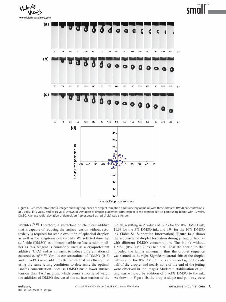
satellites. [ 24,41 ] Therefore, a surfactant or chemical additive that is capable of reducing the surface tension without cytotoxicity is required for stable evolution of spherical droplets as well as for longterm cell viability. We selected dimethyl sulfoxide (DMSO) as a biocompatible surface tension modifi er as this reagent is commonly used as a cryoprotectant additive (CPA) and as an agent to induce differentiation of cultured cells. [ 42–44 ] Various concentrations of DMSO (0, 5, and 10 vol%) were added to the bioink that was then jetted using the same jetting conditions to determine the optimal DMSO concentration. Because DMSO has a lower surface tension than TAP medium, which consists mostly of water, the addition of DMSO decreased the surface tension of the
bioink, resulting in Z values of 12.73 for the 0% DMSO ink, 11.33 for the 5% DMSO ink, and 9.94 for the 10% DMSO ink (Table S1, Supporting Information). Figure 1 a–c shows the sequences of droplet formation during jetting of bioinks with different DMSO concentrations. The bioink without DMSO (0% DMSO ink) had a tail near the nozzle tip that impeded the falling movement, thus the droplet sequence was slanted to the right. Signifi cant lateral shift of the droplet pathway for the 0% DMSO ink is shown in Figure 1 a; only half of the droplet and nearly none of the end of the jetting were observed in the images. Moderate stabilization of jetting was achieved by addition of 5 vol% DMSO to the ink. As shown in Figure 1 b, the droplet shape and pathway were
small 2016, DOI: 10.1002/smll.201502510
Figure 1. Representative photo-images showing sequences of droplet formation and trajectory of bioink with three different DMSO concentrations: a) 0 vol%, b) 5 vol%, and c) 10 vol% DMSO. d) Deviation of droplet placement with respect to the targeted lattice point using bioink with 10 vol% DMSO. Average radial deviation of deposition (represented as red circle) was 6.98 μm.

full paperswww.MaterialsViews.com
4 www.small-journal.com © 2016 Wiley-VCH Verlag GmbH & Co. KGaA, Weinheim
stable; however, lateral shift of the droplet during its fall still occurred as evidenced by the rightshifted position of the droplets in the images. In contrast, the bioink with 10 vol% DMSO exhibited stable jetting behavior; droplets were ejected perpendicularly without wandering or satellite formation. As aforementioned, the desired Z value for stable jetting is below 10; therefore, our observation that stable jetting was achieved only by tuning the Z value to 9.94 by addition of 10 vol% DMSO is consistent with previous reports. Addition of more than 10 vol% DMSO resulted in the aggregation of Chlamy cells due to the slight toxicity of DMSO, as shown in Figure S2 (Supporting Information); therefore, the optimal DMSO concentration was determined to be 10 vol% of the TAP solution.[45–47]
The targeting accuracy of the jetted bioink was evaluated by confocal microscopy to investigate the possibility of insertion of a NW array, as shown in Figure 1d. Bioink was printed on a substrate in a 10 × 10 dot pattern with a spacing between dots of 200 μm. Except for superposed dots, the landing position of each dot is indicated with respect to the lattice point of the input pattern, and the deviation of droplet from the aimed lattice points was calculated as the distance between the dot position and the target lattice point. The average radial deviation was 6.98 μm for the bioink with 10 vol% DMSO. Comparing the size of droplet and the pitch of the NWs, this extent of deviation would not hinder the fixation of Chlamy cells by inkjet printing. We therefore anticipated that our optimized bioink could result in precise inkjet printing of Chlamy cells with reasonably good targeting accuracy to a NW array.
The effects of the surface tension modifier and piezoelectricinduced stress on cell viability were evaluated by
fluorescence confocal microscopy to confirm the survival of Chlamy cells after inkjet printing, as shown in Figure 2. Viable cell counts for each sample and original optical images of fluorescent tests are shown in Figure S3 (Supporting Information). Figure 2a,b shows the autofluorescent responses of asprepared Chlamy cell inks at emission wavelengths of 640–802 nm. A living algal cell exhibits the strong autofluorescence signals due to the chlorophyll while a dead cell loses the red autofluorescence spectrum, which has been employed in the viability assay by autofluorescence observation.[48–50] On the other hand, the nonspecific green autofluorescence is observed in green algae cells regardless of their viability.[50] Chlamy cells in the ink with 10 vol% N,Ndimethylformamide (DMF) stored for 12 h only exhibited a green autofluorescent signal at emission wavelengths of 490–555 nm, as shown in Figure 2c,d. Cell shrinkage and wrinkled surface were also observed due to apoptosis or osmosis upon cell death (Figure S3, Supporting Information). In contrast, Chlamy cells in 10 vol% DMSO ink showed clear red autofluorescence signals even after 12 h of culture, as shown in Figure 2e,f. This confirms that DMSO had no significant adverse effect on the cell viability. Subsequent inkjet printing did not induce any changes in the fluorescent signals, as shown in Figure 2g,h. Thus, we concluded that the piezoelectricinduced pressure wave had no influence on the viability of the Chlamy cells.
2.2. Mechanical Modeling
Insertion of NWs into nonadherent cells has been mechanically modeled using a continuum model in which uniform
small 2016, DOI: 10.1002/smll.201502510
Figure 2. Fluorescence confocal microscopy images of Chlamy cells. a,c,e,g) Unspecific green autofluorescence at emission wavelengths of 490–555 nm. b,d,f,h) Red autofluorescence due to chlorophyll at emission wavelengths of 640–802 nm. Only bioink with 10 vol% DMF c,d) exhibited the reduced intensities of red autofluorescence accompanying shrinkage of the average cell size upon death of the cells. Shrinkage and wrinkled surfaces of dead cells can be seen more clearly in Figure S3 (Supporting Information). All scale bars represent 30 μm.

www.MaterialsViews.com
5© 2016 Wiley-VCH Verlag GmbH & Co. KGaA, Weinheim www.small-journal.com
tension is exerted on a single elastic membrane, including the lipid bilayer and cytoskeleton, by external forces such as a gravitational force and fl uid fl ow. Exact derivation of the external force resulting in penetration of the membrane is a key piece of information that is required to manipulate the insertion process. During jetting of bioinks onto NWs array, single cells will experience a gravitational force and an impulse on collision. If the force applied to a cell is insuffi cient for penetration, it could bounce and fl oat without stable fi xation. Meanwhile, excessive applied force could damage the cell and result in its bursting. Through simple mechanical consideration of a damping droplet impinged on the NWs, we derived a basic kinetic formula to calculate the optimal jetting velocity for cell membrane penetration. All sequences of inkjet printing can be expressed as the free fall of a spherical single cell at the center of a spherical droplet with an initial velocity of v 0 . We assumed that each droplet contained a single cell at its center because the average cell concentration of cells in the bioinks was around 1.3 cells per droplet, and the hydrostatic pressure in a spherical droplet can be regarded to be uniform throughout the droplet. When the droplet bumped a NW, we assumed that most of the kinetic energy became a driving force to penetrate the cell membrane. First, we considered a single cell free falling on a NW with v 0 , exerting an impulsive force on the cell. The general formula of the impulse ( I 0 ) on the freefalling cell is given by
= + 20 0
2I m v gh
(1)
where m , v 0 , g , and h are the mass of the cell, initial velocity of the cell and droplet, gravitational acceleration, and height of the nozzle from the substrate (standoff distance = 2 mm), respectively. The impulsive force ( F 0 ) applied to the cell can be derived by differentiating the impulse with respect to time ( t ), but a simple division is allowed when the force is constant over time
= = + 20
002F I
tmt v gh
(2)
When a falling cell is stopped by a NW, an inelastic collision may happen at the tip of the NW. The collision time can be expressed as the time during which the NW travels inside the cell after a collision with the velocity of v 0 . In this NW insertion model, we assumed that the penetration of the NW ended at the center of cell, so that the radius of cell could be approximated as the penetration distance
= =+ 2
cell cell
02
t rv
rv gh
(3)
The mass of a cell can be approximately calculated from the radius of the cell ( r cell ) and density ( ρ ) of the cell, which we regarded to be that of the waterbased TAP medium because the general cellular biomass dry weight of Chlamy cells is in the range of picograms [ 51 ]
ρ πρ= = 4
3 cell3m V r
(4)
By substituting Equations ( 3) and ( 4) into Equation ( 2) , the driving force for penetrating cell membrane can be written in terms of initial velocity, v 0
43 20
02
cell02F I
tr
v ghπρ ( )= = +
(5)
Based on this impulse model, we subsequently considered the motion of liquid medium when the NW hit the droplet. The interaction between the NW and liquid droplet can be described in terms of viscous drag force. The drag force induced by drag reaction of a fl uid can act on the NW when it travels through a fully enclosing fl uid, i.e., a droplet; the drag force may therefore impede the penetration of a cell by a NW. [ 52 ] It is reasonable to assume drag motion of the NW against the fl uid reservoir because the radius of a NW is much smaller than the droplet size (≈60 μm). The general equation for the drag force generated when a NW is dragged by fl uid can then be expressed as
12
12 2d d
2d 0
2tip2F c v A c v gh rρ ρ π( )= = +
(6)
where c d and r tip denote the drag coeffi cient and the tip radius of the NW, respectively. The drag coeffi cient is commonly related to the NW’s geometry and Reynolds number. We used a drag coeffi cient of 2.5 to calculate the drag force in our model, which is a reasonable value for a fl uid with a low Reynolds number (below 40). [ 53,54 ] The speed of the NW relative to the fl uid can be written as the speed of a droplet ( v ). Because the viscous drag force acts on the NW in the opposite direction of the impulsive force, the 1D force balance of exerted forces on a cell can be written as follows
πρ ( ) ( )= − = − +1
6 8 3 2*0 d cell
2d tip
202F F F r c r v gh
(7)
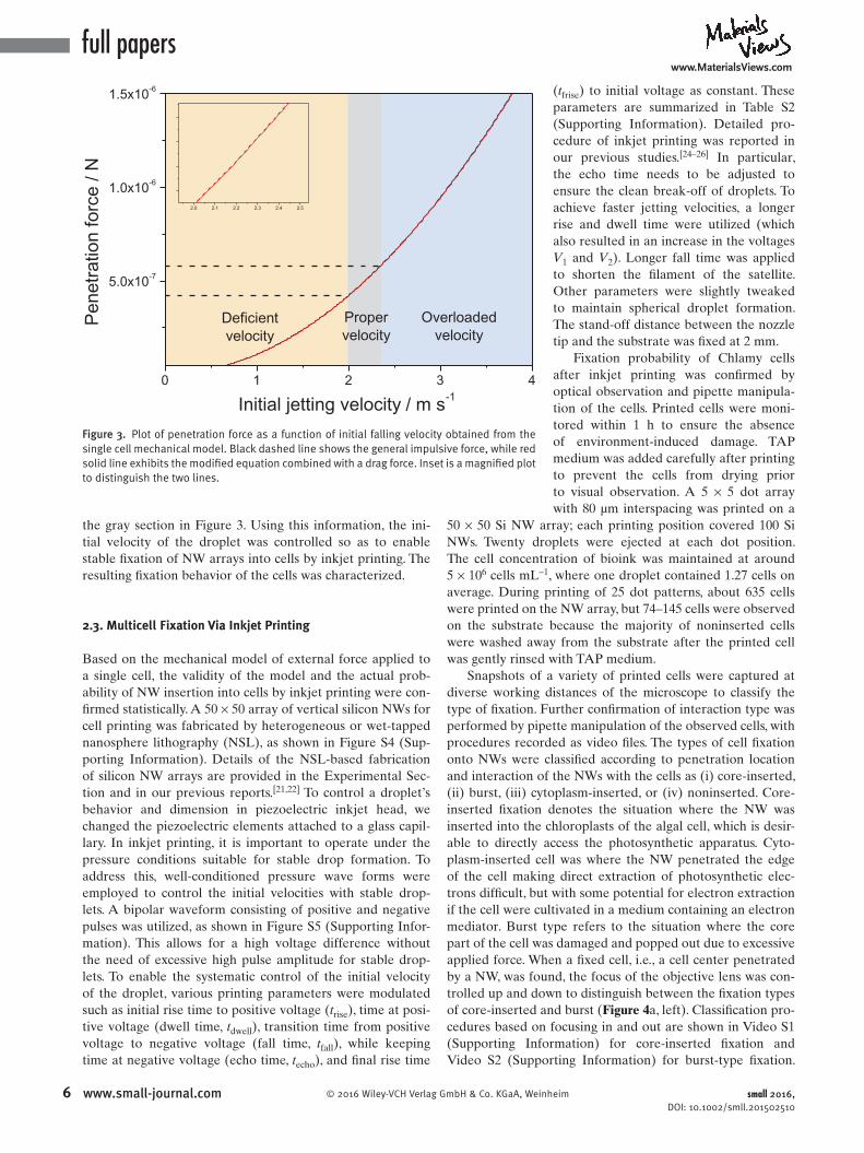
In this force balance model, the external force applied to a cell is determined by the initial velocity of the droplet; other variables are fi xed as constants. External force was plotted as a function of initial velocity, v 0 ( Figure 3 ). It should be noted that the infl uence of drag force was too small to affect the penetration behavior, resulting in little difference between plots of impulsive force (black dashed) and drag forcemodifi ed force (red solid). The infi nitesimal infl uence of drag force on the net force can be inferred from Equation ( 7) , in which the weighing constant of the initial velocity for drag force is much smaller than that for the impulsive force, because the diameter of the cell was approximated to 10 μm, while that of the tip was 600 nm. To estimate the required velocity for penetration, the force required to penetrate the cell membrane was determined experimentally using an AFM cantilever. By measuring the bending of the cantilever contacting the cell membrane when penetration occurred, we measured the force exerted on the cantilever. [ 14,17–20 ] The force required to penetrate the cell membrane was estimated to range from 396 to 566 nN for the NWs used in this experiment. [ 55 ] Based on the measured penetration force, the desired velocity was estimated to be between 1.95 and 2.34 m s −1 , as marked by
small 2016, DOI: 10.1002/smll.201502510
full paperswww.MaterialsViews.com
6 www.small-journal.com © 2016 Wiley-VCH Verlag GmbH & Co. KGaA, Weinheim
the gray section in Figure 3. Using this information, the initial velocity of the droplet was controlled so as to enable stable fixation of NW arrays into cells by inkjet printing. The resulting fixation behavior of the cells was characterized.
2.3. Multicell Fixation Via Inkjet Printing
Based on the mechanical model of external force applied to a single cell, the validity of the model and the actual probability of NW insertion into cells by inkjet printing were confirmed statistically. A 50 × 50 array of vertical silicon NWs for cell printing was fabricated by heterogeneous or wettapped nanosphere lithography (NSL), as shown in Figure S4 (Supporting Information). Details of the NSLbased fabrication of silicon NW arrays are provided in the Experimental Section and in our previous reports.[21,22] To control a droplet’s behavior and dimension in piezoelectric inkjet head, we changed the piezoelectric elements attached to a glass capillary. In inkjet printing, it is important to operate under the pressure conditions suitable for stable drop formation. To address this, wellconditioned pressure wave forms were employed to control the initial velocities with stable droplets. A bipolar waveform consisting of positive and negative pulses was utilized, as shown in Figure S5 (Supporting Information). This allows for a high voltage difference without the need of excessive high pulse amplitude for stable droplets. To enable the systematic control of the initial velocity of the droplet, various printing parameters were modulated such as initial rise time to positive voltage (trise), time at positive voltage (dwell time, tdwell), transition time from positive voltage to negative voltage (fall time, tfall), while keeping time at negative voltage (echo time, techo), and final rise time
(tfrise) to initial voltage as constant. These parameters are summarized in Table S2 (Supporting Information). Detailed procedure of inkjet printing was reported in our previous studies.[24–26] In particular, the echo time needs to be adjusted to ensure the clean breakoff of droplets. To achieve faster jetting velocities, a longer rise and dwell time were utilized (which also resulted in an increase in the voltages V1 and V2). Longer fall time was applied to shorten the filament of the satellite. Other parameters were slightly tweaked to maintain spherical droplet formation. The standoff distance between the nozzle tip and the substrate was fixed at 2 mm.
Fixation probability of Chlamy cells after inkjet printing was confirmed by optical observation and pipette manipulation of the cells. Printed cells were monitored within 1 h to ensure the absence of environmentinduced damage. TAP medium was added carefully after printing to prevent the cells from drying prior to visual observation. A 5 × 5 dot array with 80 μm interspacing was printed on a
50 × 50 Si NW array; each printing position covered 100 Si NWs. Twenty droplets were ejected at each dot position. The cell concentration of bioink was maintained at around 5 × 10⁶ cells mL−1, where one droplet contained 1.27 cells on average. During printing of 25 dot patterns, about 635 cells were printed on the NW array, but 74–145 cells were observed on the substrate because the majority of noninserted cells were washed away from the substrate after the printed cell was gently rinsed with TAP medium.
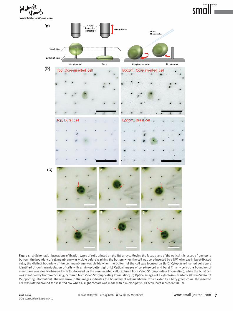
Snapshots of a variety of printed cells were captured at diverse working distances of the microscope to classify the type of fixation. Further confirmation of interaction type was performed by pipette manipulation of the observed cells, with procedures recorded as video files. The types of cell fixation onto NWs were classified according to penetration location and interaction of the NWs with the cells as (i) coreinserted, (ii) burst, (iii) cytoplasminserted, or (iv) noninserted. Coreinserted fixation denotes the situation where the NW was inserted into the chloroplasts of the algal cell, which is desirable to directly access the photosynthetic apparatus. Cytoplasminserted cell was where the NW penetrated the edge of the cell making direct extraction of photosynthetic electrons difficult, but with some potential for electron extraction if the cell were cultivated in a medium containing an electron mediator. Burst type refers to the situation where the core part of the cell was damaged and popped out due to excessive applied force. When a fixed cell, i.e., a cell center penetrated by a NW, was found, the focus of the objective lens was controlled up and down to distinguish between the fixation types of coreinserted and burst (Figure 4a, left). Classification procedures based on focusing in and out are shown in Video S1 (Supporting Information) for coreinserted fixation and Video S2 (Supporting Information) for bursttype fixation.
small 2016, DOI: 10.1002/smll.201502510
0 1 2 3 4
5.0x10⁻⁷
1.0x10⁻⁶
1.5x10⁻⁶
Overloadedvelocity
Propervelocity
2.0 2.1 2.2 2.3 2.4 2.5
P
enet
ratio
n fo
rce
/ N
Initial jetting velocity / m s-1
Deficientvelocity
Figure 3. Plot of penetration force as a function of initial falling velocity obtained from the single cell mechanical model. Black dashed line shows the general impulsive force, while red solid line exhibits the modified equation combined with a drag force. Inset is a magnified plot to distinguish the two lines.
www.MaterialsViews.com
7© 2016 Wiley-VCH Verlag GmbH & Co. KGaA, Weinheim www.small-journal.comsmall 2016, DOI: 10.1002/smll.201502510
Figure 4. a) Schematic illustrations of fi xation types of cells printed on the NW arrays. Moving the focus plane of the optical microscope from top to bottom, the boundary of cell membrane was visible before reaching the bottom when the cell was core-inserted by a NW, whereas in burst-fi xated cells, the distinct boundary of the cell membrane was visible when the bottom of the cell was focused on (left). Cytoplasm-inserted cells were identifi ed through manipulation of cells with a micropipette (right). b) Optical images of core-inserted and burst Chlamy cells; the boundary of membrane was clearly observed with top-focused for the core-inserted cell, captured from Video S1 (Supporting Information), while the burst cell was identifi ed by bottom-focusing, captured from Video S2 (Supporting Information). c) Optical images of a cytoplasm-inserted cell from Video S3 (Supporting Information). The red arrow in the images indicates the boundary of cell membrane, which exhibits a hazy green color. The inserted cell was rotated around the inserted NW when a slight contact was made with a micropipette. All scale bars represent 10 μm.
full paperswww.MaterialsViews.com
8 www.small-journal.com © 2016 Wiley-VCH Verlag GmbH & Co. KGaA, Weinheim
The other types of fixation were identified with the aid of the manipulated tip of a glass micropipette (inner diameter of 2 μm). Delicate probing with a glass pipette allowed us to move the cell around the NW by either direct contact or air pressure to confirm whether the cell was penetrated by the NW or was just adhered onto the NW, as shown in Figure 4a (right). Noninserted cells adhered to either the substrate or NW could be distinguished because they were blown away by the hydraulic pressure from the pipette tip, whereas cytoplasminserted cells could be easily recognized as they noticeably rotated around the axis of NW with a small stimulus, as shown in Video S3 (Supporting Information).
Actual images of fixation classification procedures are displayed in Figure 4b,c. For coreinserted cells, the distinct boundary of the cell membrane was visible when the lens was focused on the top of the NW, whereas the boundary was apparent in a burst cell when the bottom region was focused on (Figure 4b, captured from Videos S1 and S2 (Supporting Information)). Coreinserted cell was center positioned on the NW and the cell shape was maintained without rupture or shrinkage for up to 3 h although there was a little leakage of cytoplasm, as evidenced by the shrinkage of the cell after 3 h. Coreinserted cell fixation refers to multilayer penetration of the cell membrane and chloroplast membrane; the penetrated cell barely moved or rotated when pressure was applied with a micropipette. In contrast, when a slight contact was made by a micropipette to a cell inserted by a NW, the cell
rotated around the NW as shown in Figure 4c and Video S3 (Supporting Information). The NW was inserted in the cytoplasm between chloroplast and cell wall. Elastic deformation of the cell membrane when the cell was pushed was observed. In case of algal cells attached to the side of NWs (without penetration into cell membrane) are easily removed even with a slight contact of a micropipette. When the micropipette touching the cell was removed, the cytoplasminserted cell returned to its original position because of its interaction with the NW (Figure 4c, captured from Video S3 (Supporting Information)). These detailed verifications allowed us to confirm that living Chlamy cells were fixed onto NW arrays by inkjet printing, and that coreinserted cell fixation did occur.
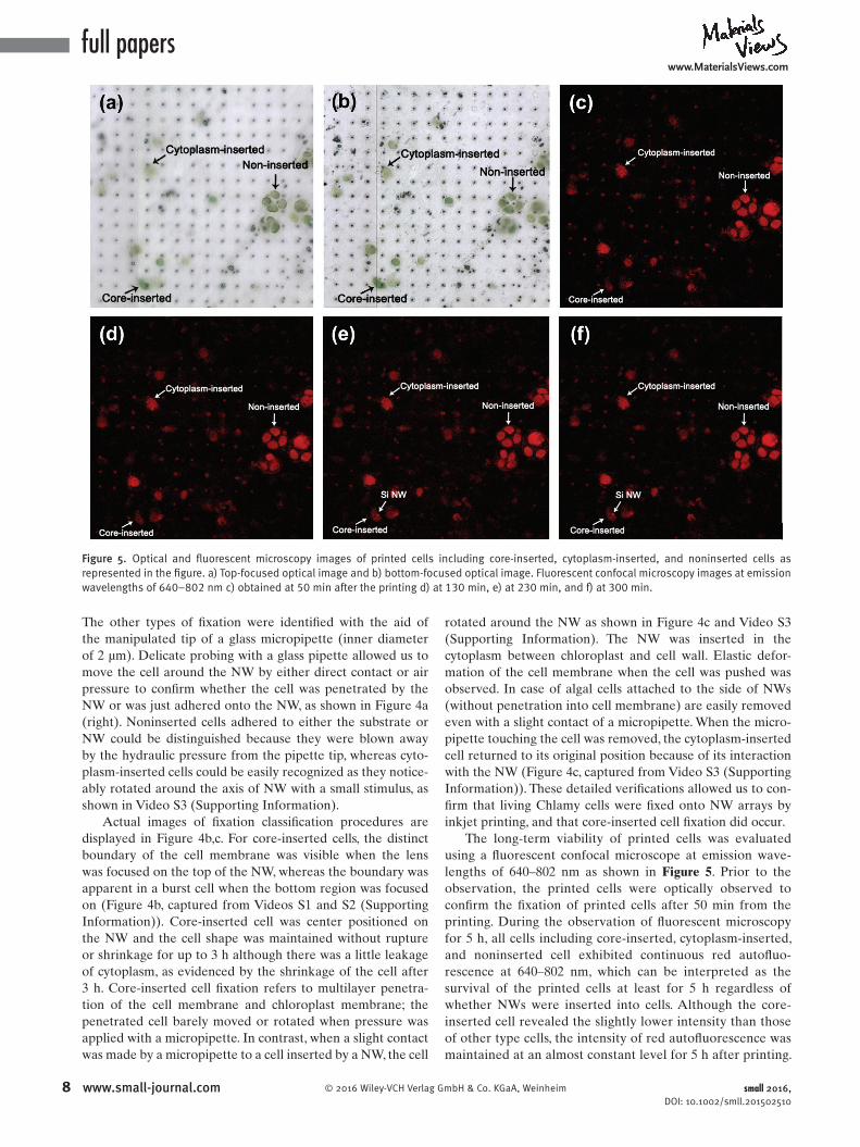
The longterm viability of printed cells was evaluated using a fluorescent confocal microscope at emission wavelengths of 640–802 nm as shown in Figure 5. Prior to the observation, the printed cells were optically observed to confirm the fixation of printed cells after 50 min from the printing. During the observation of fluorescent microscopy for 5 h, all cells including coreinserted, cytoplasminserted, and noninserted cell exhibited continuous red autofluorescence at 640–802 nm, which can be interpreted as the survival of the printed cells at least for 5 h regardless of whether NWs were inserted into cells. Although the coreinserted cell revealed the slightly lower intensity than those of other type cells, the intensity of red autofluorescence was maintained at an almost constant level for 5 h after printing.
small 2016, DOI: 10.1002/smll.201502510
Figure 5. Optical and fluorescent microscopy images of printed cells including core-inserted, cytoplasm-inserted, and noninserted cells as represented in the figure. a) Top-focused optical image and b) bottom-focused optical image. Fluorescent confocal microscopy images at emission wavelengths of 640–802 nm c) obtained at 50 min after the printing d) at 130 min, e) at 230 min, and f) at 300 min.
www.MaterialsViews.com
9© 2016 Wiley-VCH Verlag GmbH & Co. KGaA, Weinheim www.small-journal.comsmall 2016, DOI: 10.1002/smll.201502510
It is noteworthy that Si NWs showed red autofl uorescent signals because of low bandgap of Si about 1.1 eV, by which the array of Si NWs can be clearly seen in the fl uorescent microscopy. After 230 min of observation, the top of the NW inserted in the core part of the cell was detected as indicated in Figure 5 e,f. This observation indicates the complete penetration of the NW throughout the cell by continuously exerted gravitational pressure, which can be an evidence of the direct access of NW into the cell interior. In this regard, it can be concluded that the NW had been inserted into the cell interior, rather than indented the cell membrane. These types of insertion into the core part or cytoplasm of the cell do not seem to cause the apoptosis of cells at least for 5 h.
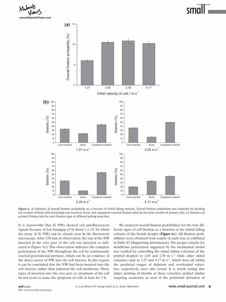
We analyzed overall fi xation probabilities for the four different types of cell fi xation as a function of the initial falling velocity of the bioink droplet ( Figure 6 a). All fi xation probabilities were obtained from counts of each case as exhibited in Table S3 (Supporting Information). The proper velocity for membrane penetration suggested by the mechanical model was verifi ed by controlling the initial falling velocities of the printed droplets to 2.05 and 2.39 m s −1 while other initial velocities such as 1.27 and 4.17 m s −1 , which were all within the predicted ranges of defi cient and overloaded velocities, respectively, were also tested. It is worth noting that inkjet printing of bioinks at these velocities yielded similar targeting accuracies as seen in the positional deviation of
1.27 2.05 2.39 4.170
5
10
15
Ove
rall
fixat
ion
prob
abili
ty (
%)
Initial velocity of cell / m s-1
Core-inserted Burst Cytoplasm-inserted0
10
20
30
40
50
60
70
80
90
100
Sta
tistic
(%
)
1.27 m s-1
Core-inserted Burst Cytoplasm-inserted0
10
20
30
40
50
60
70
80
90
100
Sta
tistic
(%
)
2.05 m s-1
Core-inserted Burst Cytoplasm-inserted0
10
20
30
40
50
60
70
80
90
100
Sta
tistic
(%
)
2.39 m s-1
Core-inserted Burst Cytoplasm-inserted0
10
20
30
40
50
60
70
80
90
100
Sta
tistic
(%
)
4.17 m s-1
(a)
(b)
Figure 6. a) Statistics of overall fi xation probability as a function of initial falling velocity. Overall fi xation probability was obtained by dividing the number of fi xed cells (including core-inserted, burst, and cytoplasm-inserted fi xated cells) by the total number of printed cells. b) Statistics of printed Chlamy cells for each fi xation type at different jetting velocities.

full paperswww.MaterialsViews.com
10 www.small-journal.com © 2016 Wiley-VCH Verlag GmbH & Co. KGaA, Weinheim small 2016, DOI: 10.1002/smll.201502510
droplets (Figure S6, Supporting Information). These observations allowed us to characterize the fixation types solely as a function of applied force by modulating the initial falling velocity of the ink droplet. Overall fixation probabilities were nearly constant at around 10% when the initial falling velocity exceeded the value of 2.05 m s−1. The probabilities of fixation for inks printed at velocities of 2.05 and 2.39 m s−1 were 10.59% and 10.9%, respectively, while that at 4.17 m s−1 was 10.29%. In contrast, only 6.04% of printed cells were fixed to NWs when the initial falling velocity was set to 1.27 m s−1. These findings demonstrated that ink falling at a theoretically deficient velocity only had a weak penetration force, resulting in a reduction in overall fixation probability. Fixation behavior was quite different for other velocities examined, especially the overloaded velocity, as shown in Figure 6b. Printing at proper and deficient velocities resulted in a minimum burst probability and a maximum cytoplasminserted probability. Coreinsertion fixation probability, which is desirable for energy harvesting, was 36.11% at the initial falling velocity of 2.05 m s−1, while it was 33.33% and 34.48% for velocities of 1.27 and 2.39 m s−1, respectively. The reason that cytoplasminserted fixation had a higher probability than coreinsertion, i.e., 50.00% for 2.05 m s−1, 55.17% for 2.37 m s−1, and 44.44% for 1.27 m s−1, is likely due to the smaller area of the core part of the cell relative to the overall cell dimensions. Printing at a deficient velocity resulted in a higher probability of burst fixation despite the low overall fixation probability. This is likely due to statistical error caused by the small number of countable printed cells for the deficient velocity than the higher velocities. The deficient and proper velocities suggested by our simple model similarly gave rise to the least probability of burst fixation. Burst fixation probability increased dramatically from 10.34% to 34.29% as the initial falling velocity increased from 2.39 to 4.17 m s−1. This difference in burst fixation probability between the overloaded velocity and other velocities implies that burst fixation occurred differently; the tip inserted into the core part of the cell resulted in leakage of stroma through the ruptured chloroplast membrane, leading to successive bursting when deficient and proper velocities were employed, while bursting occurred when the tip penetrated the membrane due to overexerted forces at the overloaded velocity. Our experimental observations clearly show that our mechanical model predicted the proper velocities for required forces to penetrate the cell membrane without damage to the cell fairly accurately. Although overall fixation probability was low compared with that of other fixation methods, our results demonstrate that the scalable and facile inkjet printing process can be employed to fix cells on NW arrays with reasonable accuracy, which could provide practical platforms for novel energyharvesting systems.
3. Conclusions
We demonstrated effective and stable insertion of NWs into Chlamy cells via scalable inkjet printing of the cells onto the NWs. To optimize bioink composed of living Chlamy cells, 10 vol% DMSO was employed as surface tension
modifier, resulting in stable droplet generation without satellite formation and accurate deposition. By optimizing the formulation of the ink and comprehensively studying jetting parameters, the average deviation relative to targeting point was minimized to 6.98 μm, indicating excellent positioning accuracy of the bioink. Fluorescence confocal microscopy confirmed that the viability of printed Chlamy cells was not influenced by DMSO addition or the printing procedures. We successfully fixated printed Chlamy cells onto vertically aligned NW arrays via inkjet printing of bioink. Simple mechanical considerations of the force applied to the cell membrane during printing allowed us to control the jetting force to ensure penetration of the cells by the NWs. Statistical analyses revealed that the overall fixation probability of NWs into Chlamy cells varied with the applied force as predicted by our mechanical model. The highest overall fixation probability of 10.9% and the desirable coreinserted probability of 34.48% among all cells fixed to NWs were observed when the bioink was printed at the initial falling velocity of 2.39 m s−1, which was in a good agreement with the predicted proper velocity range. In contrast, printing at a deficient velocity resulted in a lower overall fixation probability due to insufficient indentation force, while the appearance of burst cells increased dramatically when they were printed at an overloaded velocity. Our methodologies for fixation of NWs into cells via scalable inkjet printing of the cells represent an effective tool to harness biological energy and exploit new opportunities for lightharvesting bioelectrochemical systems.
4. Experimental Section
Bioink Preparation: Chlamy cells (CC-4348, Chlamydomonas resource center) were cultured at room temperature in TAP medium. The average diameter of Chlamy cells was 5–10 μm. The cell solution was centrifuged at 3000 rpm for 5 min and the pre-cipitates were repeatedly washed with 20 mL of TAP solution to remove impurities such as cell aggregates and organic materials. Top portion of the redispersed cell solution was decanted to pre-pare a bioink. DMSO (99.9%, Sigma-Aldrich, USA) was added at concentrations of 0, 5, and 10 vol% to the bioink to control the surface tension. The surface tension of bioink was measured by a contact angle analyzer (Phoenix Alpha, Seo Co., Korea). Cell con-centrations of bioink were maintained in the range of 1 × 10⁶ to 1 × 10⁷ cells mL−1 as determined by C-chip disposable hemocy-tometers (DHC-N01, Incyto Co., Korea).
Si NW Substrate Preparation: Monodispersed silica particles of the same size (1 μm) were sonicated for 10 min and the dispersion were then dispensed on prepatterned photoresist (PR) templates using a micropipette. Particles were physically forced into cavities by tapping the dispersion using a polyurethane (PU) swab (N4.PFB601, Daihan Scientific Co., Korea). Excessive particles on top of the templates were removed by a PU swab soaked with water. After particle loading, PR templates were etched to obtain array-pat-terned particles attached to Si substrates. Si NWs of high aspect ratios were fabricated by deep reactive-ion etching (DRIE, Multiplex ICP, STS, UK). An additional reactive-ion etching (RIE, E5, EDD, Inc., Korea) process was performed to control the size of the silica parti-cles. After both RIE and DRIE processes were completed, the silica

www.MaterialsViews.com
11© 2016 Wiley-VCH Verlag GmbH & Co. KGaA, Weinheim www.small-journal.comsmall 2016, DOI: 10.1002/smll.201502510
nanoparticles at the tip of the Si NWs were selectively etched by a buffered oxide etch (BOE) solution for 30 min followed by a rinsing with DI water. Si NW arrays with a diameter of 600 nm and length of 4.8 μm at the separation spacing of 10 μm were examined by fi eld emission scanning electron microscopy (JSM-6010LV, JEOL Ltd., Japan).
Cell Printing : An inkjet printing unit (UJ 200, Unijet Co., Korea) was equipped with a piezoelectric nozzle with an orifi ce diam-eter of 50 μm from Micro-fab technology and a charge-coupled device (CCD) camera for visual inspection of droplet formation. The nozzle was cleaned with isopropyl alcohol (IPA, anhydrous, 99.5%, Sigma-Aldrich, USA) and TAP medium to remove any microsize dust. All time parameters were set from 5 to 100 μs. The voltage V 0 was normally set to zero. The dwell voltage ( V 1 ) was set from 0 to 100 V when the echo voltage ( V 2 ) had the opposite sign ( V 1 = – V 2 ). To evaluate the positional accuracy of the bioink droplets, the radial distance deviation between the droplet-landed position and the target position was measured with a confocal laser scanning microscope (OLS3000, Olympus, Japan). During inkjet printing, the radius of the jetted droplets was maintained between 73.2 and 78.2 μm, so that the average cell number contained in one droplet was calculated from the droplet volumes and the cell con-centration of bioink; there were estimated to be 1.13–1.38 cells per droplet.
Cell Viability : Cells can be damaged by chemical or physical means. Three different cell solutions were examined: as-prepared bioink without additive, bioink with 10 vol% DMF (anhydrous, 99.8%, Sigma-Aldrich, USA) added, and bioink with 10 vol% DMSO added. Cell viability was evaluated after 12 h of aging. Using a micropipette, 10 μL of each solution was dropped on a glass slide. Cells after inkjet printing using as-prepared bioink without additive were also examined. All samples were monitored using confocal laser scanning microscopy (LSM 700, Carl Zeiss, Germany). For red autofl uorescence imaging, the excitation laser with wavelength of 639 nm and a dichroic fi lter (LP640, Molecular Devices, USA) were employed to observe the fl uorescence at wavelengths of 640–802 nm. The excitation with 488 nm laser and a dichroic fi lter (BP490, Molecular Devices, USA) were utilized for the emission of green autofl uorescence at wavelengths of 490–555 nm. The cells exhibiting the red autofl uorescence were identifi ed as live cells while the cells only showing the green autofl uorescence were regarded as dead cells. All cells in each sample were counted. Cell viability was calculated by dividing the number of live cells by the total number of cells.
Optical Observation of Cells Printed onto Nanowires : After inkjet printing, 4 mL of TAP medium was added to prevent the cells from drying prior to observation. Cells printed onto NWs were visualized by an optical cell probing system consisting of a bio-logical microscope (BX51WI, Olympus, Japan), a micro injector (IM-9B, Narishige, Japan), a motor-drive micromanipulator (MM-89, Narishige, Japan), and a three-axis hanging joystick oil hydraulic microholder (MMO-202ND, Narishige, Japan). [ 21,22 ] Cells were observed through a water immersion microscopic lens to investi-gate whether NWs were inserted into Chlamy cells. By controlling the focus of the objective lens up and down, core-inserted and burst cells were identifi ed by the distinct boundary of the cell membrane. Using the micromanipulator, not-inserted cells were examined by directly contacting or applying positive pressure to the cell using a glass micropipette (TIP2TW1, WPI Inc., USA). All
images were captured as snapshots or video fi les with TSView 7 (Tucsen Inc., China). All cell insertion behaviors were individually counted for each sample using the captured images. Insertion statistics were obtained by dividing the number of inserted cells (including cytoplasm-inserted, burst, and core-inserted cells) by the total number of printed cells.
Supporting Information
Supporting Information is available from the Wiley Online Library or from the author.
Acknowledgements
D.L. and D.L. contributed equally to this work. The authors received fi nancial support from grants from the National Research Founda-tion of Korea (NRF) funded by the Korean government (MSIP) (Nos. 2012R1A3A2026417 and 2011-002-0285).
[1] X. Chen , A. Kis , A. Zettl , C. R. Bertozzi , Proc. Natl. Acad. Sci. USA 2007 , 104 , 8218 .
[2] W. Kim , J. K. Ng , M. E. Kunitake , B. R. Conklin , P. Yang , J. Am. Chem. Soc. 2007 , 129 , 7228 .
[3] A. K. Shalek , J. T. Gaublomme , L. Wang , N. Yosef , N. Chevrier , M. S. Anderson , J. T. Robinson , N. Pochet , D. Neuberg , R. S. Gertner , I. Amit , J. R. Brown , N. Hacohen , A. Regev , C. J. Wu , H. Park , Nano Lett. 2012 , 12 , 6498 .
[4] X. Xie , A. M. Xu , S. Leal-Ortiz , Y. Cao , C. C. Garner , N. A. Melosh , ACS Nano 2013 , 7 , 4351 .
[5] C. Xie , L. Hanson , Y. Cui , B. Cui , Proc. Natl. Acad. Sci. USA 2011 , 108 , 3894 .
[6] Y.-R. Na , S. Y. Kim , J. T. Gaublomme , A. K. Shalek , M. Jorgolli , H. Park , E. G. Yang , Nano Lett. 2013 , 13 , 153 .
[7] N. Yosef , A. K. Shalek , J. T. Gaublomme , H. Jin , Y. Lee , A. Awasthi , C. Wu , K. Karwacz , S. Xiao , M. Jorgolli , D. Gennert , R. Satija , A. Shakya , D. Y. Lu , J. J. Trombetta , M. R. Pillai , P. J. Ratcliffe , M. L. Coleman , M. Bix , D. Tantin , H. Park , V. K. Kuchroo , A. Regev , Nature 2013 , 496 , 461 .
[8] T. Berthing , S. Bonde , C. B. Sørensen , P. Utko , J. Nygård , K. L. Martinez , Small 2011 , 7 , 640 .
[9] A. K. Shalek , J. T. Robinson , E. S. Karp , J. S. Lee , D.-R. Ahn , M.-H. Yoon , A. Sutton , M. Jorgolli , R. S. Gertner , T. S. Gujral , G. MacBeath , E. G. Yang , H. Park , Proc. Natl. Acad. Sci. USA 2010 , 107 , 1870 .
[10] J. T. Robinson , M. Jorgolli , A. K. Shalek , M.-H. Yoon , R. S. Gertner , H. Park , Nat. Nanotechnol. 2012 , 7 , 180 .
[11] C. Xie , Z. Lin , L. Hanson , Y. Cui , B. Cui , Nat. Nanotechnol. 2012 , 7 , 185 .
[12] W. Ryu , S.-J. Bai , J. S. Park , Z. Huang , J. Moseley , T. Fabian , R. J. Fasching , A. R. Grossman , F. B. Prinz , Nano Lett. 2010 , 10 , 1137 .
[13] P. Verma , I. Y. Wong , N. A. Melosh , Biointerphases 2010 , 5 , 37 .
[14] X. Xie , A. M. Xu , M. R. Angle , N. Tayebi , P. Verma , N. A. Melosh , Nano Lett. 2013 , 13 , 6002 .
[15] E. A. Evans , Biophys. J. 1973 , 13 , 926 . [16] E. A. Evans , R. Waugh , L. Melnik , Biophys. J. 1976 , 16 , 585 . [17] A. Hategan , R. Law , S. Kahn , D. E. Discher , Biophys. J. 2003 , 85 ,
2746 .
full paperswww.MaterialsViews.com
12 www.small-journal.com © 2016 Wiley-VCH Verlag GmbH & Co. KGaA, Weinheim small 2016, DOI: 10.1002/smll.201502510
[18] S. Sen, S. Subramanian, D. E. Discher, Biophys. J. 2005, 89, 3203.[19] E.-Y. Kwon, Y.-T. Kim, D.-E. Kim, J. Mech. Sci. Technol. 2009, 23,
1932.[20] V. Lulevich, C. C. Zimmer, H.-S. Hong, L.-W. Jin, G.-Y. Liu, Proc.
Natl. Acad. Sci. USA 2010, 107, 13872.[21] Y. H. Seo, L. H. Kim, Y.-B. Kim, W. Ryu, Nanoscale 2013, 5, 7809.[22] Y. H. Seo, L. H. Kim, F. B. Prinz, W. Ryu, RSC Adv. 2014, 4,
16655.[23] L. Hanson, Z. C. Lin, C. Xie, Y. Cui, B. Cui, Nano Lett. 2012, 12,
5815.[24] D. Jang, D. Kim, J. Moon, Langmuir 2009, 25, 2629.[25] Y. Kim, K. Woo, J. Kim, J. Moon, Ceram. Int. 2013, 39, 4961.[26] K. Woo, D. Jang, Y. Kim, J. Moon, Ceram. Int. 2013, 39, 7015.[27] C. J. Ferris, K. J. Gilmore, S. Beirne, D. McCallum, G. G. Wallace,
M. in het Panhuis, Biomater. Sci. 2013, 1, 224.[28] X. Cui, D. Dean, Z. M. Ruggeri, T. Boland, Biotechnol. Bioeng.
2010, 106, 963.[29] R. D. Boehm, P. R. Miller, J. Daniels, S. Stafslien, R. J. Narayan,
Mater. Today 2014, 17, 247.[30] J. Jia, D. J. Richards, S. Pollard, Y. Tan, J. Rodriquez, R. P. Visconti,
T. C. Trusk, M. J. Yost, H. Yao, R. R. Markwald, Y. Mei, Acta Bio-mater. 2014, 10, 4323.
[31] Q. Zheng, J. Lu, H. Chen, L. Huang, J. Cai, Z. Xu, Anal. Biochem. 2011, 410, 171.
[32] J. H. Y. Chung, S. Naficy, Z. Yue, R. Kapsa, A. Quigley, S. E. Moulton, G. G. Wallace, Biomater. Sci. 2013, 1, 763.
[33] T. Xu, J. Jin, C. Gregory, J. J. Hickman, T. Boland, Biomaterials 2005, 26, 93.
[34] T. Xu, C. A. Gregory, P. Molnar, X. Cui, S. Jalota, S. B. Bhaduri, T. Boland, Biomaterials 2006, 27, 3580.
[35] B. Lorber, W.-K. Hsiao, I. M. Hutchings, K. R. Martin, Biofabrication 2014, 6, 015001.
[36] R. E. Saunders, J. E. Gough, B. Derby, Biomaterials 2008, 29, 193.[37] C. Xu, M. Zhang, Y. Huang, A. Ogale, J. Fu, R. R. Markwald, Lang-
muir 2014, 30, 9130.
[38] S. Yamaguchi, A. Ueno, Y. Akiyama, K. Morishima, Biofabrication 2012, 4, 045005.
[39] S. V. Kumar, R. W. Misquitta, V. S. Reddy, B. J. Rao, M. V. Rajam, Plant Sci. 2004, 166, 731.
[40] B. A. Rasala, S.-S. Chao, M. Pier, D. J. Barrera, S. P. Mayfield, PLoS One 2014, 9, e94028.
[41] B. Derby, Ann. Rev. Mater. Res. 2010, 40, 395.[42] P. Huang, A. Dong, W. S. Caughey, J. Pharm. Sci. 1995, 84, 387.[43] J. O. M. Karlsson, E. A. Szurek, A. Z. Higgins, S. R. Lee, A. Eroglu,
Cryobiology 2014, 68, 18.[44] J. Paquin, B. A. Danalache, M. Jankowshi, S. M. McCann,
J. Gutkowska, Proc. Natl. Acad. Sci. USA 2002, 99, 9550.[45] G. D. Violante, N. Zerrouk, I. Richard, G. Provot, J. C. Chaumeil,
P. Arnaud, Biol. Pharm. Bull. 2002, 25, 1600.[46] R. Notman, M. Noro, B. O’Malley, J. Anwar, J. Am. Chem. Soc.
2006, 128, 13982.[47] J. Galvao, B. Davis, M. Tilley, E. Normando, M. R. Duchen,
M. F. Cordeiro, FASEB J. 2014, 28, 1317.[48] G. Agati, Pure Appl. Opt. 1998, 7, 797.[49] M. Sato, Y. Murata, M. Mizusawa, H. Iwahashi, S. Oka, Microbiol.
Cult. Coll. Dec. 2004, 20, 53.[50] K. Schulze, D. A. López, U. M. Tillich, M. Frohme, BMC Biotech.
2011, 11, 118.[51] M. Chioccioli, B. Hankamer, I. L. Ross, PLoS One 2014, 9,
e97269.[52] H. Oprins, B. Vandevelde, M. Baelmans, Micromachines 2012, 3,
150.[53] B. Huner, R. G. Hussey, Phys. Fluids 1977, 20, 1211.[54] B. Ren, W. Zhong, B. Jin, Y. Lu, X. Chen, R. Xiao, Ind. Eng. Chem.
Res. 2011, 50, 7593.[55] H. Hong, Y. Kim, W. Ryu, unpublished.
Received: August 20, 2015Revised: December 5, 2015Published online: