INOX99 - VISUAL PLUS CORPORATION · UK Mounting FR Montage ITA Installazione ESP Montaje Montage...
12
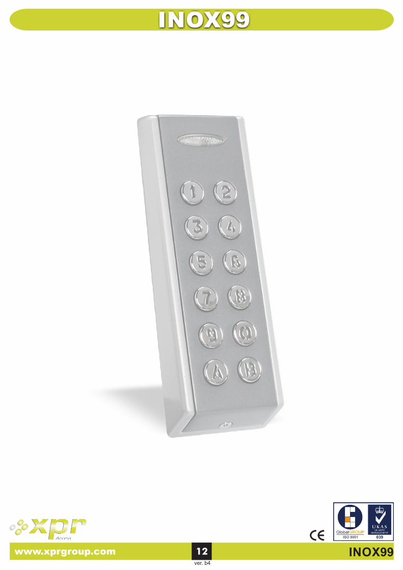
Features Caractéristiques Caratteristiche Características Merkmale UK FR ITA ESP D INOX99 : Standalone vandal resistant keypad : Mullion keypad for doorframe mounting : Backlit metallic keys : Potted aluminium cast keypad with 11-core cable : Operates on 12/24V AC/DC : Photoelectric sensor automatically adjusts the illumination level : 99 User memory (codes up to 8 digits long) : 2 outputs that operate in pulse (01 … 99 sec) or latch mode (00) : 1 Exit button : 30 sec lockout after 8 consecutive invalid codes : Dipswitch to regain default settings : Visual and audible feedback : Tamper switch for higher security : EEPROM prevents data loss during power failure : Peripherals connected via bi-directional CODIX bus : Dustproof and waterproof (IP67) : Built-in REED switch and tamper : Magnet holder provided : Current Consumption Standby: 20mA, Maximum: 70mA : Clavier autonome anti-vandale : Le clavier etroit peut être intallé sur un montant de porte : Touches rétro-éclairées : Clavier en aluminium moulé dans la résine avec un câble de 11 fils : Alimentation 12/24V CA/CC : Cellule photo-électrique ajuste automatiquement l'éclairage en fonction de la luminosité ambiante : Mémoire pour 99 Utilisateurs (codes jusqu'à 8 digits de long) : 2 sorties, en mode Impulsionnel (01…99 sec) ou en mode Marche/Arrêt (00) : 1 bouton-poussoir de sortie : Après 8 codes consécutifs erronés blocage du système pendant 30 secondes : Dipswitch pour réinitialiser la programmation d’usine : Signaux visuels et sonores : Switch d'auto-protection pour une plus grande sécurité : Mémoire EEPROM stocke les données en cas de coupure de courant : Périphériques connectés par un bus CODIX bi-directionnel : Résistant aux poussières et à l'eau (IP67) : REED switch et switch d'autoprotection incorporés : Support de l'aimant fourni : Consommation Au repos: 20 mA, Max.: 70 mA : Teclado autónomo antivandálico : Teclado estrecho para montaje en el marco de una puerta : Teclas metálicas retroiluminadas : Teclado moldeado en aluminio y encapsulado en resina, con cable de 11 hilos : Funciona con 12/24V CA/CC : Sensor fotoeléctrico que ajusta automáticamente el nivel de iluminación : 99 códigos en memoria (hasta 8 dígitos de longitud) : 2 salidas que operan en modo impulsional (01 … 99 seg.) o modo conmutación (00) : 1 Botón de salida : 30 segundos de bloqueo tras 8 códigos inválidos consecutivos : Interruptor DIP para restauración de valores por defecto : Respuesta audible y visual : Interruptor Tamper para seguridad antisabotaje : La EEPROM evita la pérdida de datos : Periféricos conectados a través de un bus CODIX bidireccional : A prueba de polvo y resistente al agua (IP67) : Interruptores reed y antisabotaje incorporados : Soporte del imán, suministrado : Consumo de corriente Reposo: 20 mA, Máx.: 70 mA : Tastiera autonoma anti-vandalica : Tastiera adatta all'installazione su profili porte : Tasti metallici retro-illuminati : Tastiera in getto d fuso con cavo ’alluminio a 11 poli : Funzionamento a 12/24V c.a./c.c. : Livello di illuminazione regolato automaticamente da un sensore fotoelettrico : Memoria da 99 codici (ciascuno lungo al massimo 8 caratteri) : 2 uscite: ad impulso (da 01 a 99 sec) o bi-stabile (00) : 1 tasto Uscita : Blocco di funzionamento per 30 sec dopo 8 tentativi di inserimento codice errato : Dipswitch per riottenere le impostazioni di default : Feedback acustico e visivo : Interruttore antimanomissione per una maggior sicurezza : EEPROM per evitare la perdita dei dati : Periferiche collegate mediante bus bidirezionale CODIX : A tenuta di polvere e stagna (IP67) : Incorporato REED Interruttore e antimanomissione : Supporto del magnete fornito : Consumo di corrente Stanby: 20 mA, Massimo: 70 mA : Vandalismussichere Standalone Tastatur : Tastatur zur Montage im Türrahmen : Metalltasten mit Hintergrundbeleuchtung : Kunstharzvergossene Tastatur mit Gehäuse aus Aluminiumdruckguss und 11-adrigem Kabel : Versorgungsspannung 12/24 AC/DC : Ein photoelektrischer Sensor passt die Hintergrundbeleuchtung automatisch an : Speicher für 99 Benutzer (PIN-Code bis zu 8 Ziffern) : 2 Ausgänge, Impuls- (01 … 99 sec) oder Schaltmodus (00) einstellbar : 1 Austrittstaster : 30 Sek. Tastatursperre bei 8 Mal in Folge eingegebenem ungültigen Code : DIP-Schalter für das Zurücksetzen auf die Werkseinstellungen : Akustisches und optisches Bestätigungssignal : Sabotageschalter für erhöhte Sicherheit : EEPROM zur Datenspeicherung, gesichert gegen Stromausfall : Peripheriegeräte können über einen bi-direktionalen CODIX-Bus angeschlossen werden : Staub- und Wasserfest (Ip67) : Integrierter Reed- und Sabotageschalter : Integrierter Magnet : Stromaufnahme im Standby 10 mA; max. 60 mA Eigenschappen NL : Standalone vandaalbestendig keypad : Smal keypad voor deurpost montage : Verlichte metalen toetsen : Gesloten alluminium keypad met 11-aderige kabel : Werkt op 12/24V AC/DC : Photoelektrische sensor stelt automatisch verlichtings niveau : 99 gebruikercodes (0 tot 8 karakters) : 2 uitgangen welke in pulsmode werken (01….99 sec) of houd mode (00) : 1 Exit drukknop : 30 sec blokkering na ingeven van 8 onjuiste codes : Dipswitch voor laden fabrieksinstellingen : Visuele en hoorbare terugkoppeling : Sabotage schakelaar voor hogere veiligheid : EEPROM voorkomt data verlies gedurende spanningsuitval : Randapparatuur kan aangesloten worden op de bi-directionele CODIX bus : Stof- en waterdicht (IP67) : Ingebouwde Reedcontact en sabotage : Magneethouder bijgeleverd : Stroomopname in rust: 20mA, Maximaal: 70mA www.xprgroup.com 1 INOX99 User Manual UK FR IT ES DE NL
Transcript of INOX99 - VISUAL PLUS CORPORATION · UK Mounting FR Montage ITA Installazione ESP Montaje Montage...
Features Caractéristiques Caratteristiche
Características Merkmale
UK FR ITA
ESP D
INOX99
: Standalone vandal resistant keypad: Mullion keypad for doorframe mounting: Backlit metallic keys: Potted aluminium cast keypad with 11-core cable: Operates on 12/24V AC/DC: Photoelectric sensor automatically adjusts the illumination level: 99 User memory (codes up to 8 digits long): 2 outputs that operate in pulse (01 … 99 sec) or latch mode (00): 1 Exit button: 30 sec lockout after 8 consecutive invalid codes: Dipswitch to regain default settings: Visual and audible feedback: Tamper switch for higher security: EEPROM prevents data loss during power failure: Peripherals connected via bi-directional CODIX bus: Dustproof and waterproof (IP67) : Built-in REED switch and tamper: Magnet holder provided: Current Consumption Standby: 20mA, Maximum: 70mA
: Clavier autonome anti-vandale : Le clavier etroit peut être intallé sur un montant de porte : Touches rétro-éclairées : Clavier en aluminium moulé dans la résine avec un câble de 11 fils : Alimentation 12/24V CA/CC : Cellule photo-électrique ajuste automatiquement l'éclairage en fonction de la luminosité ambiante : Mémoire pour 99 Utilisateurs (codes jusqu'à 8 digits de long) : 2 sorties, en mode Impulsionnel (01…99 sec) ou en mode Marche/Arrêt (00) : 1 bouton-poussoir de sortie : Après 8 codes consécutifs erronés blocage du système pendant 30 secondes : Dipswitch pour réinitialiser la programmation d’usine : Signaux visuels et sonores : Switch d'auto-protection pour une plus grande sécurité : Mémoire EEPROM stocke les données en cas de coupure de courant : Périphériques connectés par un bus CODIX bi-directionnel : Résistant aux poussières et à l'eau (IP67) : REED switch et switch d'autoprotection incorporés : Support de l'aimant fourni : Consommation Au repos: 20 mA, Max.: 70 mA
: Teclado autónomo antivandálico: Teclado estrecho para montaje en el marco de una puerta: Teclas metálicas retroiluminadas: Teclado moldeado en aluminio y encapsulado en resina, con cable de 11 hilos: Funciona con 12/24V CA/CC: Sensor fotoeléctrico que ajusta automáticamente el nivel de iluminación: 99 códigos en memoria (hasta 8 dígitos de longitud): 2 salidas que operan en modo impulsional (01 … 99 seg.) o modo conmutación (00): 1 Botón de salida: 30 segundos de bloqueo tras 8 códigos inválidos consecutivos: Interruptor DIP para restauración de valores por defecto: Respuesta audible y visual: Interruptor Tamper para seguridad antisabotaje: La EEPROM evita la pérdida de datos: Periféricos conectados a través de un bus CODIX bidireccional: A prueba de polvo y resistente al agua (IP67): Interruptores reed y antisabotaje incorporados: Soporte del imán, suministrado: Consumo de corriente Reposo: 20 mA, Máx.: 70 mA
: Tastiera autonoma anti-vandalica: Tastiera adatta all'installazione su profili porte: Tasti metallici retro-illuminati: Tastiera in getto d fuso con cavo ’alluminio a 11 poli: Funzionamento a 12/24V c.a./c.c.: Livello di illuminazione regolato automaticamente da un sensore fotoelettrico: Memoria da 99 codici (ciascuno lungo al massimo 8 caratteri): 2 uscite: ad impulso (da 01 a 99 sec) o bi-stabile (00): 1 tasto Uscita: Blocco di funzionamento per 30 sec dopo 8 tentativi di inserimento codice errato: Dipswitch per riottenere le impostazioni di default: Feedback acustico e visivo: Interruttore antimanomissione per una maggior sicurezza: EEPROM per evitare la perdita dei dati: Periferiche collegate mediante bus bidirezionale CODIX: A tenuta di polvere e stagna (IP67): Incorporato REED Interruttore e antimanomissione : Supporto del magnete fornito: Consumo di corrente Stanby: 20 mA, Massimo: 70 mA
: Vandalismussichere Standalone Tastatur: Tastatur zur Montage im Türrahmen: Metalltasten mit Hintergrundbeleuchtung: Kunstharzvergossene Tastatur mit Gehäuse aus Aluminiumdruckguss und 11-adrigem Kabel: Versorgungsspannung 12/24 AC/DC: Ein photoelektrischer Sensor passt die Hintergrundbeleuchtung automatisch an: Speicher für 99 Benutzer (PIN-Code bis zu 8 Ziffern): 2 Ausgänge, Impuls- (01 … 99 sec) oder Schaltmodus (00) einstellbar: 1 Austrittstaster: 30 Sek. Tastatursperre bei 8 Mal in Folge eingegebenem ungültigen Code: DIP-Schalter für das Zurücksetzen auf die Werkseinstellungen: Akustisches und optisches Bestätigungssignal: Sabotageschalter für erhöhte Sicherheit: EEPROM zur Datenspeicherung, gesichert gegen Stromausfall: Peripheriegeräte können über einen bi-direktionalen CODIX-Bus angeschlossen werden: Staub- und Wasserfest (Ip67): Integrierter Reed- und Sabotageschalter: Integrierter Magnet : Stromaufnahme im Standby 10 mA; max. 60 mA
EigenschappenNL
: Standalone vandaalbestendig keypad: Smal keypad voor deurpost montage: Verlichte metalen toetsen: Gesloten alluminium keypad met 11-aderige kabel: Werkt op 12/24V AC/DC: Photoelektrische sensor stelt automatisch verlichtings niveau: 99 gebruikercodes (0 tot 8 karakters): 2 uitgangen welke in pulsmode werken (01….99 sec) of houd mode (00): 1 Exit drukknop: 30 sec blokkering na ingeven van 8 onjuiste codes: Dipswitch voor laden fabrieksinstellingen: Visuele en hoorbare terugkoppeling: Sabotage schakelaar voor hogere veiligheid: EEPROM voorkomt data verlies gedurende spanningsuitval: Randapparatuur kan aangesloten worden op de bi-directionele CODIX bus: Stof- en waterdicht (IP67): Ingebouwde Reedcontact en sabotage: Magneethouder bijgeleverd: Stroomopname in rust: 20mA, Maximaal: 70mA
www.xprgroup.com 1 INOX99
User Manual UK FR IT ES DE NL
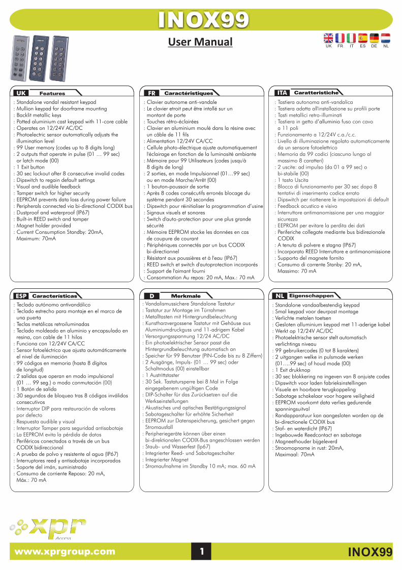
Mounting Installazione Montage Montaje Montage Montage UK FR ITA ESP D
UK FR ITA ESP D Wiring Cablaggio Câblage Cableado Verdrahtung Aansluiting
G DATA +
GND DATA +9V
Colour/ Couleur/ Colore/ Color/ Farbe/ KleurConnection/ Connexion/Connessione/ Conexión/ Anschlüsse/ Aansluiting
Tamper
Relay
Mandatory/ Obligatoire/ Obbligatorio/
Obligatorio/ Vorschrift/ Mandataris
12/24V
AC/DC
Exit
NO
C
NC
Transistor
G
NO
NC
Do not apply any voltage to the CODIX BUS.N'appliquer aucune tension au bus CODIX.Non applicare alcuna tensione al bus CODIX.No aplique ninguna tensión al bus CODIX.Keine Spannung auf den CODIX Bus zuführen.Sluit geen spanningsbron aan op de CODIX bus.
Option/ Option/ Opzione/ Opción/ optional/ Optie: 3-Wire/ 3-fil/ 3-fili/ 3-hilos/ 3-Draht/ 3-aderige CODIX bus
Red/ Rouge/ Rosso/ Rojo/ Rot/ Rood
Black/ Noir/ Nero/ Negro/ Schwarz/ Zwart
White/ Blanc/ Bianco/ Blanco/ Weiß/ Wit
Yellow/ Jaune/ Giallo/ Amarillo/ Gelb/ Geel
Grey/ Gris/ Grigio/ Gris/ Grau/ Grijs
Green/ Vert/ Verde/ Verde/ Grün/ Greon
Blue/ Bleu/ Blu/ Azul/ Blau/ Blauw
Orange/ Orange/ Arancione/ Naranja/ Orange/ Oranje
Brown/ Brun/ Bruno/ Marr n/ Braun/ Bruinó
Violet/ Violet/ Violetto/ Morado/ Violett/ Paars
Pink/ Rose/ Rosa/ Rosado/ Rosa/ Roze
Grey/ Gris/
Grigio/ Gris/
Grau/ Grijs
Violet/ Violet/
Violetto/ Morado/
Violett/ Paars
4.
1. 3.
5.
3 (M3 x 30mm CSK Philips)
6.
1 (M3 x 6mm)
2.
Magnet holder/ Support d'aimant/Supporto del magnete/ Soporte del imán/ Magnethalter/ Magneet houder
2 (M3 x 30mm CSK Philips)
Flat surface/ Surface plane/Superficie piana/Superficie llana/Flach Oberfläche/ Plat oppervlak
INOX/ MINI/ VKP/ VPROX/ LCS/MTPX
DipswitchDipswitchDipswitch
Conmutador DIPDip-Schalter
Dipswitch
DG
/WS/
00
02
IS
-01
12/24V(AC/DC)(CA/CC)
Black/ Noir/
Nero/ Negro/
Schwarz/ Zwart
NL
NL
www.xprgroup.com 2 INOX99
UK FR ITA
ESP D
INOX99
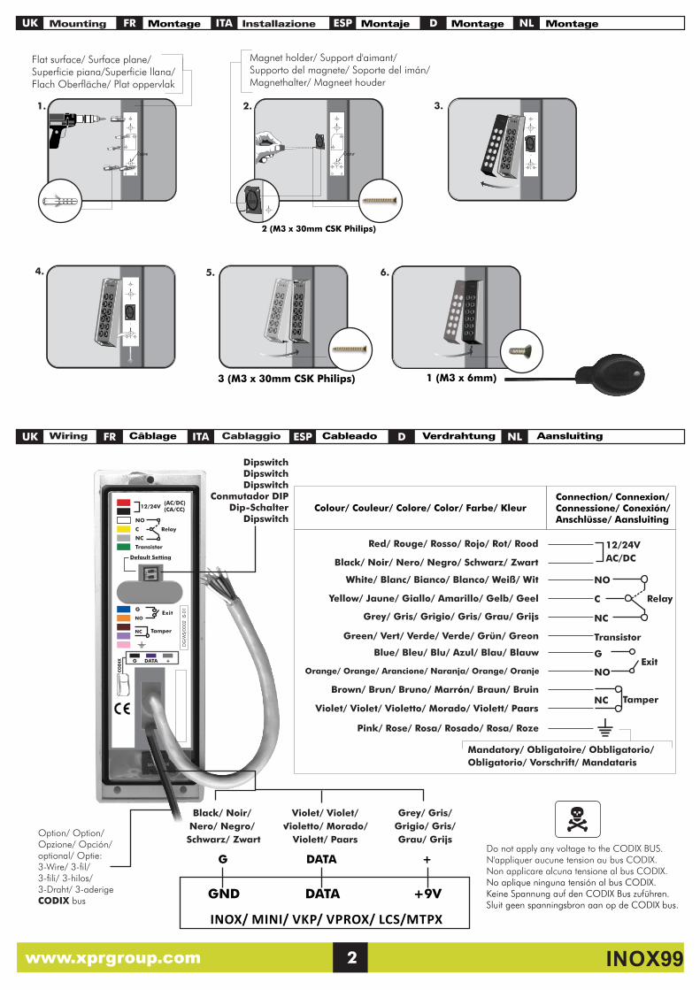
DC (CC) AC (CA) Normally open Normalement ouvert Normalmente aperto Normalmente abierto Arbeitskontakt Open Normaal
Strike Gâche
InnescoCerraduraTüröffner
Slot
Common Commun Comune Común Wechselkontakt Gemeenschappelijk
Connecting the transistor Raccorder le transistor Collegamento transistor
Conexión del transistor Transistor anschließen Aansluiten van de transistor
UK FR ITA
ESP D
Transistor: Ptot=250 mW (Vce x Ic), Vceo max = 30V, Ic max. (DC (CC) = 100 mA
White/ Blanc/
Bianco/ Blanco/
Weiß/ Wit
Yellow/ Jaune/
Giallo/ Amarillo/
Gelb/ Geel
Grey/ Gris/
Grigio/ Gris/
Grau/ Grijs
INOX99
White/ Blanc/
Bianco/ Blanco/
Weiß/ Wit
Yellow/ Jaune/
Giallo/ Amarillo/
Gelb/ Geel
Grey/ Gris/
Grigio/ Gris/
Grau/ Grijs
UK FR
ITA
ESP D
Green LED indicates activation of relay output whereas Red LED indicates activation of transistor output.
La Led verte indique l'activation du relais de sortie, alors que la Led rouge indique l'activation du transistor de sortie.
Il LED verde indica l'attivazione dell'uscita relè, mentre il LED rosso indica l'attivazione dell'uscita transistor.
El LED verde indica activación de la salida de relé mientras que el LED rojo indica activación de la salida transistor.
Die grüne LED zeigt die Aktivierung des Relaisausgangs, die rote LED die Aktivierung des Transistorausgangs an
Exit button Pulsante uscita Bouton de sortie Botón de salida Austrittstaster UK ITA ESPFR D
Exit button (NO) automatically activates relay output.Le bouton-poussoir (NO) active automatiquement le relais de sortie.Il bottone per l'uscita (NO) attiva automaticamente l'uscita relè. El pulsador (NO) activa automáticamente la salida de relé.Durch den Austrittstaster (NO) wird der Relaisausgang automatisch aktiviert.Exit drukknop (NO) activeert automatisch de relais uitgang.
Blue/ Bleu/
Blu/ Azul/
Blau/ BlauwPB
INOX99
Orange/ Orange/
Arancione/ Naranja/
Orange/ Oranje
Connecting strike to the relay Connexion d'une gâche au relais Collegamento innesco ai relè
Conexión de una cerradura al relé Türöffner mit Relais verbinden Aansluiten sloten op de relais
Relay/ Relais/ Relè/ Relé/ Relais/ Relais: 2A
INOX99
Normally closed Normalement fermé Normalmente chiuso Normalmente cerrado Ruhekontakt Normaal gesloten
Green/ Vert/
Verde/ Verde/
Grün/ GroenT Output 2
NL
NL
NL
Groene LED geeft aan dat het relais bekrachtigd is en de rode LED geeft de transistoruitgang weer
Exit drukknopNL
Green and Red LEDs for output status Leds rouge et verte pour l'état de sortie
LED verde e rosso per la segnalazione dello stato di funzionamento
LEDs rojo y verde para mostrar el estado de las salidas Grüne und rote LED zur Statusanzeige
Groene en Rode LEDs voor uitgang status
www.xprgroup.com 3 INOX99
Note: The transistor output can be only used when the device is powered with DC Voltage 12 -24 Vdc.Note: La sortie transistorisée peut être seulement utilisé quand l'appareil est alimenté en 12/24 VDC.Nota: L'uscita transistor puo essere soltanto utilizzata quando l'apparrechiatura è alimentata in 12/24 VDC Nota: La salida transistorizada sólo puede ser usada cuando el aparato este alimentado en 12/24VDC.Bitte beachten: Der Transistorausgang kann nur verwendet werden, wenn das Gerät mit 12/24VDC betrieben wirdOpmerking: De transistor uitgang kan alleen gebruikt worden wanneer het apparaat is ingeschakeld met 12/24 VDC.
NO
COM
NC
NO
COM
NC
- +
+
+
-
DC Diode1N4007-
Capacitor + Resistor Condensateur + Résistance Condensatore + Resistenza Condensador + ResistenciaKondensator + WiderstandCondensator + Weerstand
10K 1/2W
AC
470nF~
~
~ ~
NC:
COM:
NO:
UK FR ITA
ESP D
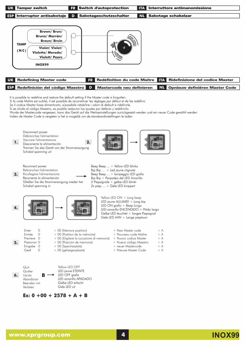
Redefining Master code Redéfinition du code Maître Ridefinizione del codice Master
Redefinición del código Maestro Mastercode neu definieren Opnieuw definiëren Master Code
It is possible to redefine and restore the default setting if the Master code is forgotten.
.
Si le code Ma tre est oublié, il est possible de reconstituer les réglages par défaut et de les redéfinir.î
Si se olvida el código Maestro, es posible restaurar los ajustes por defecto y redefinirlo.
Se il codice Master fosse dimenticato, e'possibile ristabilire i valori di default e ridefinirle.
Wurde der Mastercode vergessen, kann das Gerät auf die Werkseinstellungen zurückgesetzt werden und ein neuer Code gewählt werdenIndien de Master Code is vergeten is het is mogelijk om de standaardinstellingen te laden
Tamper switch Switch d'autoprotection Interruttore antimanomissione
Interruptor antisabotaje Sabotageschutzschalter Sabotage schakelaar
UK ITA
ESP
FR
D
TAMP
( N C )
INOX99
Brown/ Brun/
Bruno/ Marr n/ ó
Braun/ Bruin
Violet/ Violet/
Violetto/ Morado/
Violett/ Paars
1.
3.
5.
4.
6. B
Ex: 0 +00 + 2578 + A + B
Disconnect power Débranchez l'alimentation Staccare l'alimentazioneDesconecte la alimentaciónTrennen Sie das Gerät von der StromversorgungSchakel spanning uit
Reconnect powerRebranchez l'alimentation Ricollegare l'alimentazione Reconecte la alimentación SStellen Sie die Stromversorgung wieder herSchakel spanning in
Yellow LED OFFLED jaune ETEINTELED OFF gialloLED amarillo APAGADOGelbe LED erlischtGele LED uit
Beep Beep ... + Yellow LED blinksBip Bip ... + Led jaune clignoteBeep Beep ... + lampeggio LED gialloBip Bip + Parpadeo del LED Amarillo2 Piepsignale + gelbe LED blinkt2x piep…. + Gele LED knippert
Yellow LED ON + Long beepLED jaune ALLUMEE + Long bipLED ON giallo + Beep lungoLED amarillo ENCENDIDO + Pitido largoGelbe LED leuchtet + langes PiepsignalGele LED AAN + Lange pieptoon
QuitQuitter UscitaAbandonarBeenden mit Verlaten
2.
Enter 0 + 00 (Memory position) + New Master code + AEntrée 0 + 00 (Position de la mémoire) + Nouveau code Maître + APremere 0 + 00 (Digitare la Locazione di memoria) + Nuovo codice Master + A Presionar 0 + 00 (Posición de memoria) + Nuevo código Maestro + AEingabe 0 + 00 (Speicherplatz) + neuer Mastercode + A Geef 0 + 00 (geheigenplaats) + Nieuwe Master Code + A
NL
NL
www.xprgroup.com 4 INOX99
UK
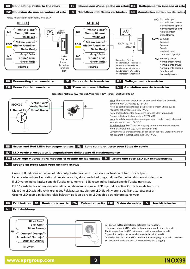
Validate by pressing (B)
Validation OK?NO
YES
Start
Enter “Master Code” OR “000” (if first time use)
Multiple small beeps +
Yellow LED blinks rapidly
1 small beep + 1 long beep + Yellow LED is ‘ON’
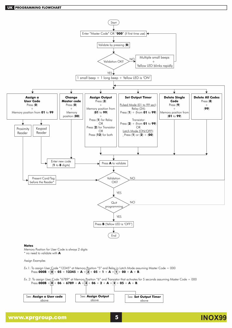
NotesMemory Position for User Code is always 2 digits * no need to validate with A
Assign Examples
Ex.1: To assign User Code “12345” at Memory Position “5” and Relay in Latch Mode assuming Master Code = 000 Press 000B + 0 + 05 + 12345 + A + 3 + 05 + 1 + A + 1 + 00 + A + B.
Ex. 2: To assign User Code “6789” at Memory Position “6” and Transistor that activates for 5 seconds assuming Master Code = 000 Press 000B + 0 + 06 + 6789 + A + 3 + 06 + 2 + A + 2 + 05 + A + B.
See: Assign a User code above
See: Assign Outputabove
See: Set Output Timerabove
Press A to validate
Assign a User Code
Press (0)+
Memory position from 01 to 99
Assign OutputPress (3)
+Memory position from
(01 to 99)+
Press (1) for Relay OR
Press (2) for TransistorOR
Press (12) for both
Set Output Timer
Pulsed Mode (01 to 99 sec): Relay (2A):
Press (1) + (from 01 to 99)
Transistor:Press (2) + (from 01 to 99)
ORLatch Mode (ON/OFF): Press (1) or (2) + (00)
Delete Single Code
Press (9)+
Memory position from(01 to 99)
Enter new code(1 to 8 digits)
Delete All CodesPress (8)
+(99)
KeypadReader
Proximity Reader
Change Master code
Press (0)+
Memory position (00)
PROGRAMMING FLOWCHART
Press B (Yellow LED is ‘OFF’)
NO
YES
End
Validation OK?
Present Card/Tag before the Reader*
Quit programming
YES
NO
www.xprgroup.com 5 INOX99
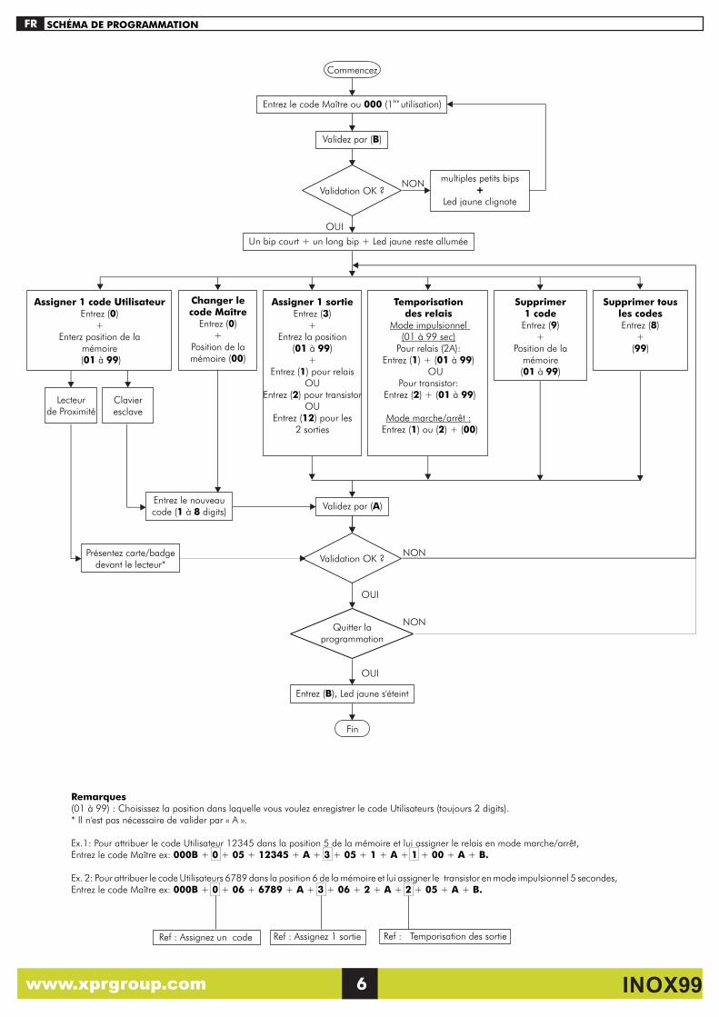
SCHÉMA DE PROGRAMMATIONFR
Validez par (B)
Validation OK ?NON
OUI
Commencez
ère Entrez le code Maître ou 000 (1 utilisation)
multiples petits bips+
Led jaune clignote
Un bip court + un long bip + Led jaune reste allumée
Validez par (A)
Assigner 1 code UtilisateurEntrez (0)
+Enterz position de la
mémoire (01 à 99)
Assigner 1 sortie Entrez (3)
+Entrez la position
(01 à 99)+
Entrez (1) pour relais OU
Entrez (2) pour transistorOU
Entrez (12) pour les 2 sorties
Temporisation des relais
Mode impulsionnel (01 à 99 sec)
Pour relais (2A):Entrez (1) + (01 à 99)
OUPour transistor:
Entrez (2) + (01 à 99)
Mode marche/arrêt : Entrez (1) ou (2) + (00)
Supprimer 1 code
Entrez (9)+
Position de la mémoire(01 à 99)
Entrez le nouveau code (1 à 8 digits)
Supprimer tous les codes Entrez (8)
+(99)
Remarques(01 à 99) : Choisissez la position dans laquelle vous voulez enregistrer le code Utilisateurs (toujours 2 digits).* Il n'est pas nécessaire de valider par « A ».
Ex.1: Pour attribuer le code Utilisateur 12345 dans la position 5 de la mémoire et lui assigner le relais en mode marche/arrêt, Entrez le code Maître ex: 000B + 0 + 05 + 12345 + A + 3 + 05 + 1 + A + 1 + 00 + A + B.
Ex. 2: Pour attribuer le code Utilisateurs 6789 dans la position 6 de la mémoire et lui assigner le transistor en mode impulsionnel 5 secondes, Entrez le code Maître ex: 000B + 0 + 06 + 6789 + A + 3 + 06 + 2 + A + 2 + 05 + A + B.
Ref : Assignez un code Ref : Assignez 1 sortie Ref : Temporisation des sortie
Clavier esclave
Lecteur de Proximité
Changer le code Maître
Entrez (0) +
Position de la mémoire (00)
NONPrésentez carte/badgedevant le lecteur*
Validation OK ?
Entrez (B), Led jaune s'éteint
NON
OUI
Fin
Quitter la programmation
OUI
www.xprgroup.com 6 INOX99
PROGRAMMAZIONE
Convalidare con B
Convalida OK ?NO
SI
Inizio
Inserire il Codice Master oppure 000 (primo utilizzo)
Ripetuti brevi Beeps + l
ampeggio LED giallo
Un brevi Beep + un lungo Beep + LED Giallo Acceso
Convalidare con (A)
Memorizzare un codice Utente
Premere (0)+
Digitare la Locazione di memoria (01 … 99)
Assegnare un relè ad un utente
Premere (3) +
Digitare la locazione di memoria (01 ... 99)
+Premere (1) per relè
OPPUREPremere (2) per transistor
OPPUREPremere (12) per entrambi i relè
Settare lo stato del relèModo impulsivo
(da 01 a 99 secondi):Per relè (2 A):
Premere 1 + (01 a 99) OPPURE
Per transistor:Premere 2 + (01 a 99)
Modo bi-stabile (ON/OFF):Premere 1 OPP. 2 + (00)
Cancellare un coidce Utente
Premere (9)+
Digitare la locazione
di memoria(01 ... 99)
Premere nuovo codice (da 1 a 8 cifre)
Per cancellare TUTTI i
codici utentePremere (8)
+ (99)
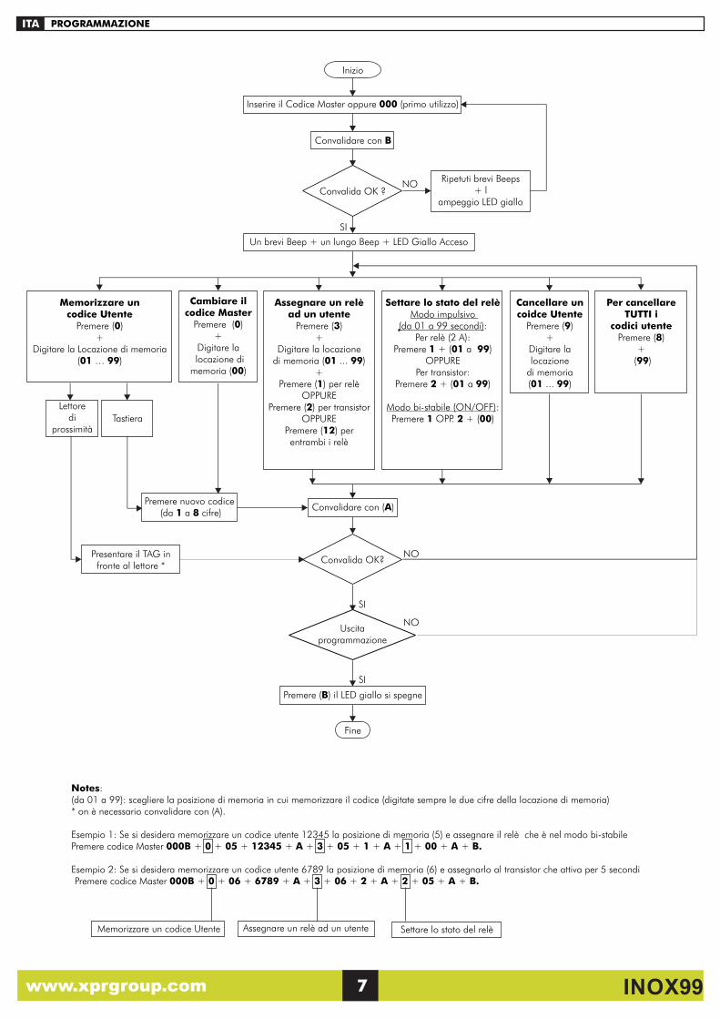
Notes:(da 01 a 99): scegliere la posizione di memoria in cui memorizzare il codice (digitate sempre le due cifre della locazione di memoria)* on è necessario convalidare con (A).
Esempio 1: Se si desidera memorizzare un codice utente 12345 la posizione di memoria (5) e assegnare il relè che è nel modo bi-stabile Premere codice Master 000B + 0 + 05 + 12345 + A + 3 + 05 + 1 + A + 1 + 00 + A + B.
Esempio 2: Se si desidera memorizzare un codice utente 6789 la posizione di memoria (6) e assegnarlo al transistor che attiva per 5 secondi Premere codice Master 000B + 0 + 06 + 6789 + A + 3 + 06 + 2 + A + 2 + 05 + A + B.
Memorizzare un codice Utente Assegnare un relè ad un utente Settare lo stato del relè
Tastiera
Lettore di
prossimità
Cambiare il codice Master
Premere (0)+
Digitare la locazione di memoria (00)
ITA
NO
SI
Presentare il TAG in fronte al lettore *
Convalida OK?
Premere (B) il LED giallo si spegne
NO
SI
Fine
Uscita programmazione
www.xprgroup.com 7 INOX99
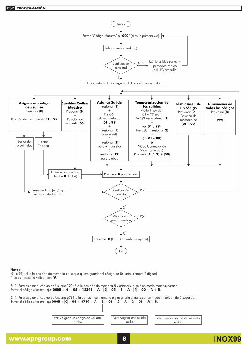
Validar presionando (B)
¿Validación correcta?
NO
SÍ
Inicio
Entrar “Código Maestro” ó “000” (si es la primera vez)
Múltiples bips cortos +
parpadeo r pido ádel LED amarillo
1 bip corto + 1 bip largo + LED amarillo encendido
Presionar A para validar
Asignar un código de usuario Presionar (0)
+ Posición de memoria de 01 a 99
Asignar Salida Presionar (3)
+ Posición
de memoria de (01 a 99)
+ Presionar (1) para el relé
ó Presionar (2)
para el transistor ó
Presionar (12) para ambos
Temporarización de los salidas
Modo Impulsión (01 a 99 seg.):
Relé (2 A): Presionar (1) +
(de 01 a 99). Transistor :Presionar (2)
+ (de 01 a 99)
ó Modo Conmutación (Marcha/Parada):
Presionar (1) ó (2) + (00)
Eliminación de un código
Presionar (9) + Posición de memoria de (01 a 99)
Entrar nuevo código de (1 a 8 dígitos)
Eliminación de todos los códigos
Presionar (8) +
(99)
Notas:(01 a 99): elija la posición de memoria en la que quiere guardar el código de Usuario (siempre 2 dígitos)* No es necesario validar con “A”
Ej. 1: Para asignar el código de Usuario 12345 a la posición de memoria 5 y asignarle el relé en modo marcha/parada. Entrar el código Maestro ej.: 000B + 0 + 05 + 12345 + A + 3 + 05 + 1 + A + 1 + 00 + A + B.
Ej. 1: Para asignar el código de Usuario 6789 a la posición de memoria 6 y asignarle el transistor en modo impulsión de 5 segundos. Entrar el código Maestro ej.: 000B + 0 + 06 + 6789 + A + 3 + 06 + 2 + A + 2 + 05 + A + B.
LectorTeclado
Lector de
proximidad
PROGRAMACIÓN
Cambiar Código Maestro
Presionar (0) +
Posición de memoria (00)
ESP
Ver: Asignar un código de Usuarioarriba
Ver: Temporización de los relésarriba
Ver: Asignar una salidaarriba
NO
SÍ
Presentar la tarjeta/tag en frente del Lector
¿Validación correcta?
Presionar B (El LED amarillo se apaga)
NO
SÍ
Fin
Abandonar programación
www.xprgroup.com 8 INOX99
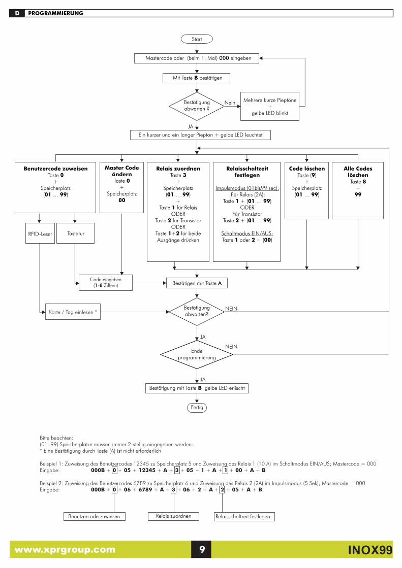
PROGRAMMIERUNG
Mit Taste B bestätigen
Bestätigung abwarten ?
Nein
JA
Start
Mastercode oder (beim 1. Mal) 000 eingeben
Mehrere kurze Pieptöne+
gelbe LED blinkt
Ein kurzer und ein langer Piepton + gelbe LED leuchtet
Bestätigen mit Taste A
Benutzercode zuweisenTaste 0
+Speicherplatz (01 … 99)
Relais zuordnenTaste 3
+Speicherplatz(01 … 99)
+Taste 1 für Relais
ODERTaste 2 für Transistor
ODERTaste 1+2 für beide Ausgänge drücken
Relaisschaltzeit festlegen
Impulsmodus (01bis99 sec): Für Relais (2A):
Taste 1 + (01 … 99)ODER
Für Transistor:Taste 2 + (01 … 99)
Schaltmodus EIN/AUS:Taste 1 oder 2 + (00)
Code löschenTaste (9)
+Speicherplatz (01 … 99)
Code eingeben (1-8 Ziffern)
Alle Codes löschenTaste 8
+99
Bitte beachten:(01..99) Speicherplätze müssen immer 2-stellig eingegeben werden.* Eine Bestätigung durch Taste (A) ist nicht erforderlich
Beispiel 1: Zuweisung des Benutzercodes 12345 zu Speicherplatz 5 und Zuweisung des Relais 1 (10 A) im Schaltmodus EIN/AUS; Mastercode = 000 Eingabe: 000B + 0 + 05 + 12345 + A + 3 + 05 + 1 + A + 1 + 00 + A + B
Beispiel 2: Zuweisung des Benutzercodes 6789 zu Speicherplatz 6 und Zuweisung des Relais 2 (2A) im Impulsmodus (5 Sek); Mastercode = 000 Eingabe: 000B + 0 + 06 + 6789 + A + 3 + 06 + 2 + A + 2 + 05 + A + B.
Benutzercode zuweisen Relais zuordnen
TastaturRFID-Leser
Master Code ändernTaste 0
+Speicherplatz
00
D
Relaisschaltzeit festlegen
NEIN
JA
Karte / Tag einlesen *Bestätigung abwarten?
Bestätigung mit Taste B gelbe LED erlischt
NEIN
JA
Fertig
Ende programmierung
www.xprgroup.com 9 INOX99
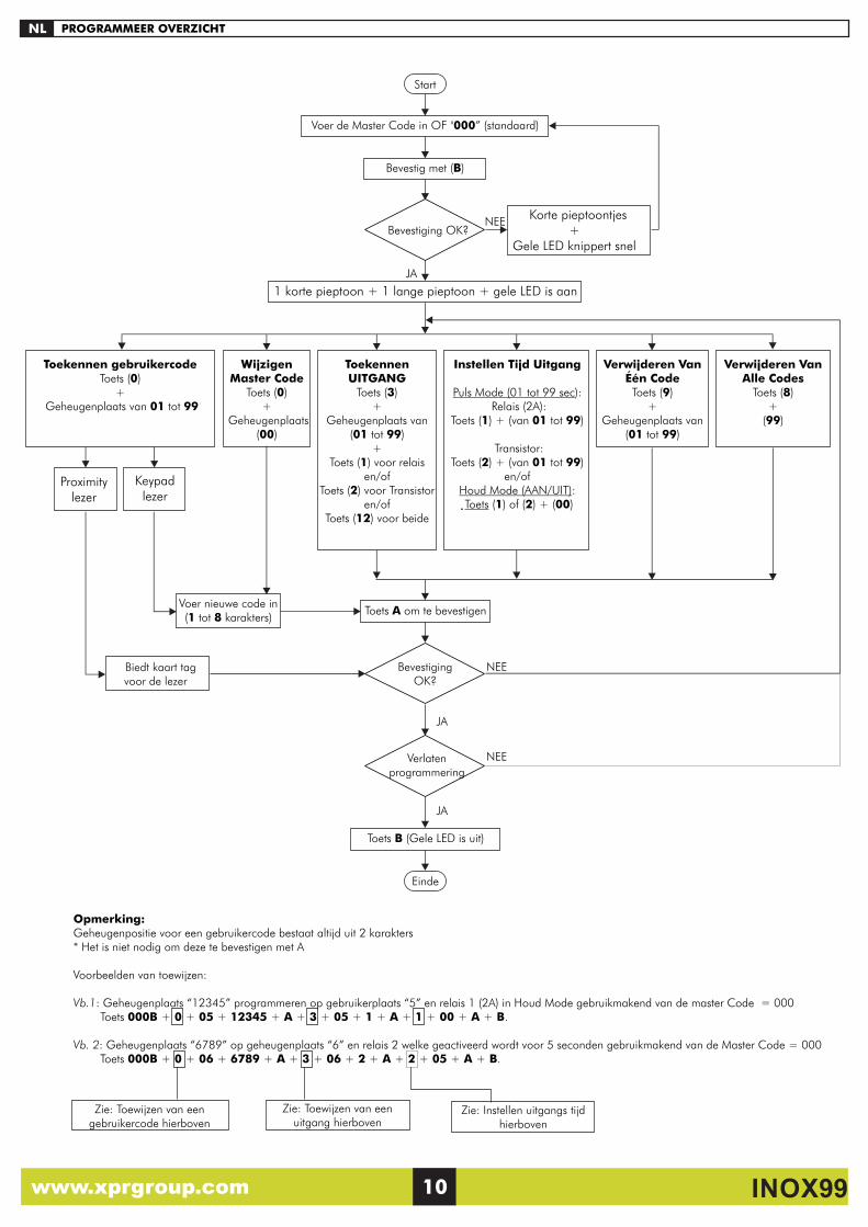
NL
Bevestig met (B)
Bevestiging OK?NEE
JA
Start
Voer de Master Code in OF "000” (standaard)
Korte pieptoontjes +
Gele LED knippert snel
1 korte pieptoon + 1 lange pieptoon + gele LED is aan
Opmerking: Geheugenpositie voor een gebruikercode bestaat altijd uit 2 karakters * Het is niet nodig om deze te bevestigen met A
Voorbeelden van toewijzen:
Vb.1: Geheugenplaats “12345” programmeren op gebruikerplaats “5” en relais 1 (2A) in Houd Mode gebruikmakend van de master Code = 000 Toets 000B + 0 + 05 + 12345 + A + 3 + 05 + 1 + A + 1 + 00 + A + B.
Vb. 2: Geheugenplaats “6789” op geheugenplaats “6” en relais 2 welke geactiveerd wordt voor 5 seconden gebruikmakend van de Master Code = 000 Toets 000B + 0 + 06 + 6789 + A + 3 + 06 + 2 + A + 2 + 05 + A + B.
Zie: Toewijzen van een gebruikercode hierboven
Zie: Toewijzen van een uitgang hierboven
Zie: Instellen uitgangs tijd hierboven
Toets A om te bevestigen
Toekennen gebruikercodeToets (0)
+ Geheugenplaats van 01 tot 99
Toekennen UITGANG
Toets (3)+
Geheugenplaats van(01 tot 99)
+Toets (1) voor relais
en/of Toets (2) voor Transistor
en/of Toets (12) voor beide
Instellen Tijd Uitgang
Puls Mode (01 tot 99 sec): Relais (2A):
Toets (1) + (van 01 tot 99)
Transistor:Toets (2) + (van 01 tot 99)
en/ofHoud Mode (AAN/UIT): Toets (1) of (2) + (00)
Verwijderen Van Één CodeToets (9)
+Geheugenplaats van
(01 tot 99)
Voer nieuwe code in (1 tot 8 karakters)
Verwijderen Van Alle Codes
Toets (8)+
(99)
Keypadlezer
Proximity lezer
Wijzigen Master Code
Toets (0)+
Geheugenplaats(00)
PROGRAMMEER OVERZICHT
Toets B (Gele LED is uit)
NEE
JA
Einde
Bevestiging OK?
Biedt kaart tag voor de lezer
Verlaten programmering
JA
NEE
www.xprgroup.com 10 INOX99
www.xprgroup.com 11 INOX99
Warranty: VPC warrants its products to be free from defects in material and workmanship for 24 months from the date of shipment. The product is to be installed in accordance with VPC's instructions and the unit should not be modified or tampered with. VPC does not assume any responsibility for damages arising from misuse of the product. VPC's sole responsibility is limited to the repair or replacement when the product is sent to VPC’s facility.Drève Richelle 161, Bâtiment G, WOP - Bte 34, 1410 Waterloo - Belgium
Garantie: VPC garantit ses produits au regard des défauts matériels et ce pendant 24 mois à compter de la date d'expédition. Le produit doit être installé conformément aux instructions de VPC et l'unité ne doit pas être modifiée ou manipulée. VPC n'endosse aucune responsabilité pour les dommages résultant d'une mauvaise utilisation du produit. La responsabilité de VPC se limite à la réparation ou à son remplacement, le produit ayant été retourné à VPC.Drève Richelle 161, Bâtiment G, WOP - Bte 34, 1410 Waterloo - Belgium
Garanzia: VPC garantisce che i suoi prodotti sono esenti da difetti dei materiali e di fabbricazione per 24 mesi dalla data di consegna. Il prodotto deve essere installato secondo le istruzioni fornite da VPC e l'unità non deve essere modificata o manomessa. VPC non si assume alcuna responsabilità per danni derivanti da un utilizzo errato del prodotto. La responsabilità di VPC si limita alla riparazione o alla sostituzione del prodotto, previo l'invio di quest'ultimo allo stabilimento VPC.Drève Richelle 161, Bâtiment G, WOP - Bte 34, 1410 Waterloo - Belgium
Garantía: VPC garantiza que sus productos carecen de defectos de materiales y mano de obra durante 24 meses a partir de la fecha de expedición. El producto debe instalarse de acuerdo con las instrucciones de VPC y no debe modificarse ni manipularse indebidamente la unidad. VPC no asume ninguna responsabilidad por daños surgidos por el mal uso del producto. La única responsabilidad de VPC se limita a la reparación o sustitución, si se envía el producto a las instalaciones de VPC.Drève Richelle 161, Bâtiment G, WOP - Bte 34, 1410 Waterloo - Belgium
Garantie: VPC garantiert für die Dauer von 24 Monaten ab Lieferdatum, dass die Produkte keine Material- und Verarbeitungsfehler aufweisen. Das Produkt ist gemäß den Anweisungen von VPC zu installieren. Änderungen oder andere Eingriffe sind untersagt. VPC übernimmt keine Haftung für Schäden, die infolge einer unsachgemäßen Verwendung des Produkts entstanden sind. Die Gewährleistung beschränkt sich ausschließlich auf die Reparatur oder den Austausch des Produktes, sofern dieses an die Betriebsstätte von VPC eingesandt wurde.Drève Richelle 161, Bâtiment G, WOP - Bte 34, 1410 Waterloo - Belgium
UK
ITA
ESP
D
Garantievoorwaarden: VPC garandeert dat de producten vrij zijn van materiaal- en of productiefouten gedurende de tijd van 24 maanden na verzending. Het product dient volgens de gelden normen en installatievoorschriften, opgesteld door VPC, te worden behandeld en gemonteerd. Bij modificatie van het product vervalt per direct de garantie. VPC neemt geen verantwoordelijkheid voor schade voortvloeiende uit onechtgebruik van het product. De verantwoording van VPC beperkt zich tot het repareren en of vervangen van het product mits deze geretourneerd zijn naar VPC.Drève Richelle 161, Bâtiment G, WOP - Bte 34, 1410 Waterloo - Belgium
NL
FR
UK This product herewith complies with requirements of EMC directive 2014/30/EU. In addition it complies with RoHS directive EN50581:2012
ITA Il presente prodotto è conforme ai requisiti della direttiva EMC 2014/30/UE. È, inoltre, conforme alla direttiva RoHS EN50581:2012
D
NL
Le produit décrit en cela est conforme aux exigences de la directive CEM 2014/30/EU. En outre, il est conforme à la directive RoHS EN50581:2012FR
ESP Este producto cumple con los requisitos de la directiva EMC 2014/30/UE. Además cumple con la normativa RoHS, directiva EN50581:2012
Dieses Produkt erfüllt die Anforderungen der EMV Richtlinie 2014/30/EU, sowie die RoHS Richtlinie EN50581:2012.
Dit product voldoet hierbij aan de vereisten van EMC-richtlijn 2014/30/EU. Het voldoet ook aan RoHS-richtlijn EN50581:2012
www.xprgroup.com 12 INOX99
INOX99
ver. b4