Innovative installation with SMISSLINE Plug-in protection ... · 2 Incoming terminal block with a...
28
Innovative installation with SMISSLINE Plug-in protection devices
Transcript of Innovative installation with SMISSLINE Plug-in protection ... · 2 Incoming terminal block with a...

Innovative installation with SMISSLINEPlug-in protection devices

2 Plug-in protection devices | Innovative installation with SMISSLINE
Where safety and adaptability are paramount, planners, building owners, and users alike choose SMISSLINE by ABB.
Because quality-conscious professionals know: adaptability and modularity are the nuts and bolts of electrical distribution systems, both in the planning phase and during implementation.
Building services engineering is characterised by increasing auto mation. This has a huge impact on electrical distribution systems and safety systems: They must keep up with the ever increasing demands and complexity. SMISSLINE, the plug-in system from ABB with integrated bus-bars, simplifies the planning, set up and maintenance of electrical systems.
SMISSLINE Pluggable-SystemFor flexible, modular Installation
Innovative installation with SMISSLINE | Plug-in protection devices 3
Contents
Plan exactly what you want! 4 System overview 6Socket, additional socket and busbars 8Varied options for individual customer requirements 10This is how it’s done: SMISSLINE assembly 12Power supply for the plug-in socket system 14Power supply via incoming terminal block or an incoming terminal component 16Power supply via protection devices 18Back-up protection with the High Performance circuit breaker S800 19SMISSLINE protection devices and accessories 20Overload and short-circuit protection 22Customer benefits offered by the vertical construction with SMISSLINE 24Combination of devices 25Successful in any location 26

4 Plug-in protection devices | Innovative installation with SMISSLINE
Plan exactly what you want!
The idea SMISSLINE protection devices are simply snapped into a plug-in socket system. The arduous task of power supply and connection is done. In addition to savings in time and money, another advantage of the system is the quick and easy exchangeability of the devices. If the corresponding spare capacity is planned, subsequent expansion consists merely of plugging in and connecting additional devices.
Avoid uneven loadsThe phase connection can be identified without removing the devices.
Collective alarm, signallingSignal and auxiliary contacts are available for all devices. These can be powered directly by the two auxiliary busbars in the socket.
A collective alarm can easily be implemented using the signal contact SK400 SA. A very good space-saving arrangement is created when the signal contact is mounted to the left or right of the miniature circuit breaker.
Vertical designA vertical design will save you even more space, as no terminal blocks are required. The outgoing cables are connected directly to the devices.
Time-saving assemblySMISSLINE simplifies planning and speeds up the set-up and assembly of power distribution systems. Components are replaced in seconds, making expansion much easier.

Innovative installation with SMISSLINE | Plug-in protection devices 5
Flexibility up to the last minuteSMISSLINE makes it possible to press ahead with planning, even before all the details of a system are known. Loads can be easily reassigned. Even if the usage of an entire installation is completely changed, the effort involved remains small.
Motor starter units or external devicesYou can create various combinations of devices using a combi module. For example, a motor protection switch, together with a contactor can be combined to form one single unit and plugged in as a whole. External devices can be integrated into the system via universal adapters.
Freedom to design and arrangeSMISSLINE gives you freedom of choice: Mixed-pole arrangement of all devices next to each other are possible.
Plugs in directlySMISSLINE devices can be snapped directly into the plug-in socket system. The input wiring is integrated within the device.

6 Plug-in protection devices | Innovative installation with SMISSLINE
System overview
Supply terminal1 Incoming terminal block with a max. current rating 2 of 160 A 50 mm2 (2 x 25 mm2) + 2 x 10 mm2 (LA, LB)Surge arrester OVR4043 Manual motor starter4 Device latch5 Miniature circuit breaker S400 M6 MDRC DIN Rail product7 Cover for busbar8 Busbar isolator9
RCBO FS40310 RCBO FS40111 Residual-current circuit breaker F40212 Residual-current circuit breaker F40413 Busbar L3 or DC +, –14 Busbar L2 or DC +, –15 Busbar L1 or DC +, –16 Busbar N17 Sockets, 8-module and 6-module18 Auxiliary busbar LA19 Auxiliary busbar LB20 Busbar N, external21 Busbar PE, external22 Additional socket23 N and PE terminals 32 A 1 mm24 2 to 10 mm2, 63 A 16 mm2 to 50 mm2 and 100 A 16 mm2 to 95 mm2, red and orange terminals for DCIncoming block 63 A25
1415161719201821
2223
9 10 11 12 136 7 854
3
21
2425

Innovative installation with SMISSLINE | Plug-in protection devices 7
29
8
24
21
23
30
18
2 26 9
27
2829
31
24
30
20
519
2017
1615
14
924
Incoming terminal component, centre power supply 26 200 A, maximum 95 mm2
DIN adapter27 Universal adapter with a current rating of 32 A and 63 A28 Combi module with a current rating of 32 A29 Socket end piece on left and right30 Dummy block and 18 mm cover with DIN top for the 31 additional socket

8 Plug-in protection devices | Innovative installation with SMISSLINE
Socket, additional socket and busbars
SocketThe socket with integrated busbars incorporates both mechanical and electrical connection to the mains supply for plug-in devices.
Socket – technical dataRated voltage: 690 V~ −Rated current: Busbars: 100 A − Centre power supply: 200 A Auxiliary busbars: 40 ASocket lengths: 6 modules (108 mm) − 8 modules (144 mm)
Socket componentsThe sockets are easy to mount. They can either be screwed onto a mounting plate or snapped onto a 35 mm DIN rail. The latch of the snap mounting makes installation par ticularly easy. It ensures the sockets can be moved laterally or re-moved before defining the final mounting position.
In order to determine the required socket length, the space necessary for
the required devices −the incoming terminal block and −any spare slots must be specified. −

Innovative installation with SMISSLINE | Plug-in protection devices 9
Snap mountingUsing a screwdriver, pull down the slide until it latches in position (socket is adjustable)
Pressure applied from the front: Lock position (sockets fixed)
Socket selection table
Modules Socket Number
length of sockets
incl. end 8 6
piece module module
in mm
6 148 – 1
8 186 1 –
12 256 – 2
14 292 1 1
16 328 2 –
18 364 – 3
20 401 1 2
22 437 2 1
24 473 3 –
26 509 1 3
28 545 2 2
30 581 3 1
32 617 4 –
34 653 2 3
36 689 3 2
38 725 4 1
40 761 5 –
42 797 3 3
Modules Socket Number
length of sockets
incl. end 8 6
piece module module
in mm
44 883 4 2
46 869 5 1
48 905 6 –
50 941 4 3
52 977 5 2
54 1013 6 1
56 1049 7 –
58 1085 5 3
60 1122 6 2
62 1158 7 1
64 1194 8 –
66 1230 6 3
68 1266 7 2
70 1302 8 1
72 1338 9 –
74 1374 7 3
76 1410 8 2
Modules Socket Number
length of sockets
incl. end 8 6
piece module module
in mm
78 1446 9 1
80 1482 10 –
82 1518 8 3
84 1554 9 2
86 1590 10 1
88 1626 11 –
90 1662 9 3
92 1698 10 2
94 1734 11 1
96 1770 12 –
98 1806 10 3
100 1843 11 2
102 1879 12 1
104 1915 13 –
106 1951 11 3
108 1943 12 2
110 2031 13 1
Additional socketThe additional socket can be simply plugged in to the socket and serves the purpose of accepting the external N and/or PE busbars. It can also be snapped onto a top-hat rail. Ad-ditional sockets can either be equipped with an N busbar or a PE busbar. Each socket can be expanded with an additional socket.

NL1L2L3
PEN
LALB
10 Plug-in protection devices | Innovative installation with SMISSLINE
Varied options for individual requirements
Socket end piece (with screw mounting)On one hand, this end piece is used for fixing the plug-in socket system to the mounting rail (particularly important for vertical assembly). On the other hand, it is also used for fixing the busbars in the socket as well as providing a shock-proof covering at the front end of the socket. Total width of the socket end piece: 2 x 21 mm.
BusbarsThe busbars with a dimension of 10 x 3 mm carry currents of up to 100 A. They are galvanically-coated. This ensures per- fect connection of the devices. The maximum delivery length of the busbar is 1979 mm. The same busbar is used for mounting in the socket (L1, L2, L3, N) as with assembly in the additional sockets (N, PE). The busbars are inserted in the socket from the front.
Auxiliary busbars LA, LBThe 5 x 2 mm auxiliary busbars are used to supply power to the auxiliary and signal contacts.
They are also galvanically-coated and their maximum delivery length is 1979 mm. In the same way as the main busbars, the auxiliary busbars are fitted from the front in the LA and LB fixtures. Of course, it is also possible to fit only one auxiliary busbar.
Threaded bolt for cover (customer-side assembly)

Z200
336.
eps
Z20
286.
eps
Z20
287
Z20
0310
.eps
Innovative installation with SMISSLINE | Plug-in protection devices 11
Busbar isolatorIf there are several isolated residual current protected device groups within a distribution system, the busbar system must be divided into the corresponding number of segments. The clearly visible dark grey busbar isolator serves as a spacial and electrical insulator for the busbars.
Busbar coverThe busbars can be shock-protected where spare slots or modules are currently not used. The 4-part covers for the socket are broken off in the required number and snapped onto the socket. Their holes allow the voltage on the bus-bars to be measured, without having to remove the cover. An 18 mm wide cover is available for the additional socket. Longer busbar sections can be protected with a cable duct cover.
N and PE terminalsThe additional socket can be equipped with plug-in terminals. These are mounted by simply plugging in, in line with the SMISSLINE philosophy.
Park position of neutral conductor terminal e.g. for insulation measuring

Device latch
12 Plug-in protection devices | Innovative installation with SMISSLINE
This is how it’s done
1. The individual sockets are butt-mounted in the desired length on the mounting rails of the distribution cabinet. The sockets can, however, also be butt-mounted on a work bench, for example, equipped with busbars and mounted in the distribution cabinet as a complete unit.
2. The busbars and any auxiliary busbars can be cut into
lengths and snapped in place.
3. In doing so, any necessary splits in the busbars must
be bridged with the busbar isolator.
4. The incoming terminal block is plugged in and the feeder cables are connected.
5. The devices are plugged in ...
6. ... and the outgoing cables are connected. Finished!

Innovative installation with SMISSLINE | Plug-in protection devices 13
7. Disconnect the devices by pressing on the front on the device latch
The starter pack makes it easyThe starter pack contains sockets, equipped with 3 or 4 busbars as required. These are already connected and ready for use. There is therefore no need to assemble the individual components.
Solutions available Type name Solutions available Type name
Startpackage 20PLE ZLS204E20-3L Startpackage 44PLE ZLS204E44-3L
Startpackage 20PLE ZLS204E20-3LN Startpackage 44PLE ZLS204E44-3LN
Startpackage 22PLE ZLS204E22-3L Startpackage 46PLE ZLS204E46-3L
Startpackage 22PLE ZLS204E22-3LN Startpackage 46PLE ZLS204E46-3LN
Startpackage 24PLE ZLS204E24-3L Startpackage 48PLE ZLS204E48-3L
Startpackage 24PLE ZLS204E24-3LN Startpackage 48PLE ZLS204E48-3LN
Startpackage 26PLE ZLS204E26-3L Startpackage 52PLE ZLS204E52-3L
Startpackage 26PLE ZLS204E26-3LN Startpackage 52PLE ZLS204E52-3LN
Startpackage 30PLE ZLS204E30-3L Startpackage 58PLE ZLS204E58-3L
Startpackage 30PLE ZLS204E30-3LN Startpackage 58PLE ZLS204E58-3LN
Startpackage 32PLE ZLS204E32-3L Startpackage 62PLE ZLS204E62-3L
Startpackage 32PLE ZLS204E32-3LN Startpackage 62PLE ZLS204E62-3LN
Startpackage 34PLE ZLS204E34-3L Startpackage 64PLE ZLS204E64-3L
Startpackage 34PLE ZLS204E34-3LN Startpackage 64PLE ZLS204E64-3LN
Startpackage 36PLE ZLS204E36-3L Startpackage 72PLE ZLS204E72-3L
Startpackage 36PLE ZLS204E36-3LN Startpackage 72PLE ZLS204E72-3LN
Startpackage 38PLE ZLS204E38-3L Startpackage 80PLE ZLS204E80-3L
Startpackage 38PLE ZLS204E38-3LN Startpackage 80PLE ZLS204E80-3LN
Startpackage 40PLE ZLS204E40-3L
Startpackage 40PLE ZLS204E40-3LN
AdvantagesOnly one order number and one price −Pre-assembled −Simple solution −Easy handling −Low storage requirements −
14 Plug-in protection devices | Innovative installation with SMISSLINE
Power supply for the busbar system
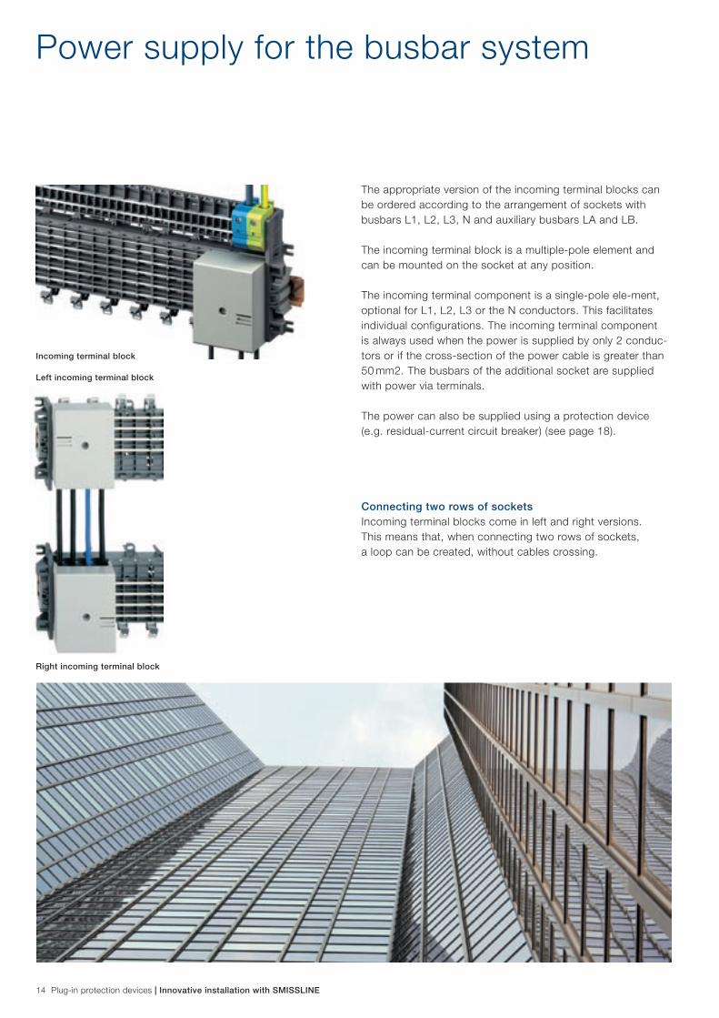
The appropriate version of the incoming terminal blocks can be ordered according to the arrangement of sockets with busbars L1, L2, L3, N and auxiliary busbars LA and LB.
The incoming terminal block is a multiple-pole element and can be mounted on the socket at any position.
The incoming terminal component is a single-pole ele-ment, optional for L1, L2, L3 or the N conductors. This facilitates individual configurations. The incoming terminal component is always used when the power is supplied by only 2 conduc-tors or if the cross-section of the power cable is greater than 50 mm2. The busbars of the additional socket are supplied with power via terminals.
The power can also be supplied using a protection device (e.g. residual-current circuit breaker) (see page 18).
Connecting two rows of socketsIncoming terminal blocks come in left and right versions. This means that, when connecting two rows of sockets, a loop can be created, without cables crossing.
Left incoming terminal block
Right incoming terminal block
Incoming terminal block

Innovative installation with SMISSLINE | Plug-in protection devices 15
Technical data for the incoming terminal blockIncoming terminal block
Rated voltage: 400/690 V −Rated current: 160 A −Space required: 4 modules − (3 PN + LA, LB)Main terminals: 50 mm − 2 cable, 35 mm2 stranded wireAuxiliary terminals: 10 mm − 2 cable, 6 mm2 stranded wire
Technical data for the incoming terminal componentIncoming terminal component
Rated voltage: 400/690 V −Rated current: 200 A −Space required: 2 modules per pole −Main terminals: 95 mm − 2 stranded wireAuxiliary terminals: not possible −
Power supply to the auxiliary busbars LA and LBBoth auxiliary busbars of the socket can be supplied with power via the incoming terminal block. The two auxiliary terminals are simply plugged into the available openings in the incoming terminal block as required. Both auxiliary busbars can carry a load of up to 40 A. In this way, auxiliary and signal contacts can be supplied with power via the auxiliary bus- bars LA and LB.
Looping the feeder cables via the incoming terminal blockThe feeder cables can be connected to the incoming terminal block from the right, the left, from below and provided that no auxiliary busbars LA and LB are required from above. The upper sections of the main terminals are detach-able to facilitate the connecting of looped conductors.

Output circuits ∑ IN: any
Power supply using an incoming terminal block (external or centre)
Upstream overcurrent protection device, current rating of 100 A
16 Plug-in protection devices | Innovative installation with SMISSLINE
Power supply for higher currents
The following points must be observed: 1. Correct configuration of the power supply 2. Correct rating of the upstream overcurrent protection
device
The maximum current rating of the upstream overcurrent protection device is 100 A
Upstream overcurrent protection device 100 A current rating 160 A, f = diversity factor
Output circuits IN: any
IN x f 100 A IN x f 100 A
Power supply using an incoming
terminal componentCentre
Output circuits IN x f 100 A
Output circuits IN x f 100 A
Together IN: max. 200 A
Power supply with centre
incoming terminal component
Innovative installation with SMISSLINE | Plug-in protection devices 17
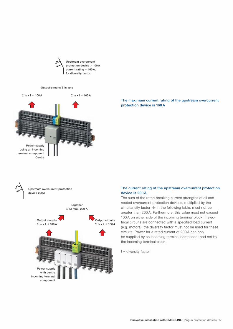
The maximum current rating of the upstream overcurrent protection device is 160 A
The current rating of the upstream overcurrent protection device is 200 AThe sum of the rated breaking current strengths of all con-nected overcurrent protection devices, multiplied by the simultaneity factor «f» in the following table, must not be greater than 200 A. Furthermore, this value must not exceed 100 A on either side of the incoming terminal block. If elec-trical circuits are connected with a specified load current (e.g. motors), the diversity factor must not be used for these circuits. Power for a rated current of 200 A can only be supplied by an incoming terminal component and not by the incoming terminal block.
f = diversity factor
Upstream overcurrent protection device 200 A

f = diversity factor
I max. 63 A = IN x f
I max. 63 A = IN x fdownstream devices
18 Plug-in protection devices | Innovative installation with SMISSLINE
Power supply via protection devices
Direct power supply from below via a residual-current circuit breaker, switch disconnector or surge arresterThe feeder cable is connected to the same side of the device as the strand wires of the plug contacts. Particular care must be taken to ensure that the sum of the current ratings of all downstream protection devices does not exceed the current rating of 63 ampere taking account of the diversity factor f.
Power supply from above via a residual-current circuit breaker or switch disconnectorThe feeder cable is connected to the opposite side of the stranded wires for the plug contacts via a residual-current circuit breaker or switch disconnector. In this configuration the busbars and thus all subsequent devices are residual current protected (when power is supplied via a residual-current circuit breaker). If several residual current groups are used, the dark grey busbar isolator should be used to separate the busbars. For this purpose, it is necessary to conform with the standards relating to overcurrent protection of residual-current circuit breakers.
Number Diversity
of electrical circuits factor (f)
2 and 3 0,8
4 to 6 0,7
7 to 9 0,6
10 and more 0,5
Table from EN 60439-3

S800
S400
Innovative installation with SMISSLINE | Plug-in protection devices 19
Back-up protection with S800
E. S800S B, C, D, K
L. Icu [kA] 50In [A] 25 32 40 50 63 80 100 125
50 0.5…2 50 50 50 50 50 50 50 5025 3...20 50 50 50 50 50 50 50 50
S400M
S450MC, K 15
25 50 50 50 50 50 5032 50 50 50 50 5040 50 50 50 5050 50 50 5063 50 50
S800S – S400M/S450M (SMISSLINE) @ 230/400 V
E. S800S B, C, D, K
L. Icu [kA] 50In [A] 25 32 40 50 63 80 100 125
S400MS450M
B, D
Icn [kA] 4*…16 50 50 50 50 50 50 50 50
10
20 50 50 50 50 50 50 5025 50 50 50 50 50 5032 50 50 50 50 5040 50 50 50 5050 50 50 5063 50 50
* applies only to B characteristic
Example for the back-up protection coordination between miniature circuit breakers and the heavy duty circuit breaker S800S at 230/400 V. Further coordination tables can be found in the technical catalogue.
The High Performance circuit breaker S800 can provide backup protection for the SMISSLINE system. The High Performance MCB S800 is directly snapped onto the top-hat rail. Power is supplied to the plug-in socket system via a short power line and an incoming terminal block.

20 Plug-in protection devices | Innovative installation with SMISSLINE
Devices and accessories
Miniature circuit breaker S4001-, 2-, 3- and 4-pole devices with a current rating between −0.5 A and 63 A Characteristics B, C, D, K, UC-Z, UC-C −Snap on auxiliary and signal contacts on the left and right −Snap on neutral disconnector with double deck terminal on −the right
Technical data in accordance with EN 60898-1S400E, M B, C, D
Rated voltage Un~: 230/400 V AC
Rated voltage Un=: 60 V = 1-pole
125 V = 2-polig
Rated frequency fn: 50/60 Hz
Rated switching capacity Icn: 6 kA (E) und 10 kA (M)
Number of poles: 1, 2, 3, 4 (3 P + N)
Approvals (without UC): S+, VDE
CCC only for 10 kA C
characteristics DNV, GL
Technical data in accordance with EN 60947-2S400M C, K
Rated voltage Un~: max. 254/400 V AC
Rated voltage Un=: 60 V = 1-pole
125 V = 2-pole
Rated frequency fn: 50/60 Hz
Rated switching capacity Icu: 50 kA 0.5 A 2 A
at 230/400 V 25 kA 2 A 20 A
15 kA 25 A
(S400 M-K 10 kA)
Number of poles: 1, 2, 3, 4 (3 P + N)
Approvals (without UC): S+, VDE (only C characteristics)
CCC, DNV, GL
Residual current device F402, F4042-pole residual-current circuit breaker 25 A to 40 A, −10, 30, 100 mA4-pole residual-current circuit breaker 25 A to 63 A, −30, 100, 300 mAShort time delay type FIK (does not react to discharge −currents)Selective residual-current circuit breaker type − S (selective to FI or FIK)
Technical data in accordance with EN 61008-1Type F402 F404
Rated voltage Un: 230 V AC 230/400 V AC
Current rating In=: 25–40 A 25–63 A
Rated tripping currents: 10, 30, 100, 300 mA 30, 100, 300 mA
Short time delayed, selective: K K and S
Approvals: S+, VDE, DNV, S+, VDE, DNV,
GL, CCC GL, CCC

Innovative installation with SMISSLINE | Plug-in protection devices 21
Combined RCBO FS401, FS403Rated breaking capacity up to 10 kA −Snap-on auxiliary and signal contacts on the left −Short time delayed versions FIK −(does not react to discharge currents)
Technical data in accordance with EN 61009-1Type FS401 FS403
Rated voltage Un: 230 V AC 230/400 V
Current rating In: 10 A up to 32 A 10 A up to 25 A
Rated breaking capacity Icn: 10 kA up to and with 16 A 10 kA up to 16 A
6 kA from 20 A 6 kA
20 A and 25 A
Rated tripping current: 10 mA and 30 mA 30 mA
Short time delayed version available
Surge arrester 404 OVR4-pole protection device, type 2 −Potential-free signal contact integrated in the device −Rated discharge surge current I − sn 15 kA
Technical data in accordance with EN 61643-11Rated voltage Un: 230/400 V AC
Max. back-up fuse: 160 A gL/gG 25 kA
Protection device: Typ 2 (IEC 61643-1)
Rated discharge surge current IS: (8/20μs) 15 kA
Max. rated discharge surge current ISmax: (8/20μs) 30 kA
Protection level: 1,5kV
Power motor protection circuit breaker MS325Power motor protection circuit breaker MS325 Un 690 V, In 0.1 to 25 A, breaking capacity 100/50 kA, with phase failure protection, temperature compensation and slide-in under-voltage release.
Switch disconnector IS404SMISSLINE switch disconnector, directly pluggable with a maximum current rating of In 63 A.
Auxiliary and signal contactsThe plug-in socket system gives you the option of signalling via auxiliary busbars. The auxiliary busbars LA and LB can be contacted directly via contacting parts. The contacting parts can be easily changed from LA to LB by replugging them, or they can be removed completely. A collective alarm is pos-sible using the innovative collective alarm signal contact. To do this, contact is made parallel with the auxiliary busbars.

LALBNL1L2L3
LALBNL1L2L3
22 Plug-in protection devices | Innovative installation with SMISSLINE
Overload and short-circuit protection
Protection of the socket system without an upstream overcurrent protection deviceAn important factor for the protection of the busbar system (sockets, incoming terminal block, incoming terminal compo-nent, adapter, combi module or terminals) is the size of the rated surge current Ipk. This is 17 kA. The busbar system can withstand a prospective rated short circuit current of up to 12 kA (measured according to EN 60439-1).
Protection of the plug-in socket system with an upstream overcurrent protection deviceIf, on the power supply side, a circuit breaker of the type Sace Tmax 200 A, a High Performance MCB S800 or a NH fuse is positioned upstream of the busbar system, then due to the short-circuit current limiting effect of this protection device, a large prospective short-circuit current of up to 50 kA for the plug-in socket system is permissible.

Innovative installation with SMISSLINE | Plug-in protection devices 23
Overload and short-circuit protection for miniature circuit breakersIf the prospective short-circuit current at the installation loca-tion of a miniature circuit breaker is not greater than its rated breaking capacity, no back-up protection via an upstream overcurrent protection device is necessary.
If the prospective short-circuit current at the installation loca-tion of the miniature circuit breaker is greater than its rated breaking capacity, the current ratings of the upstream over-current protection device must not exceed the table values in the back-up protection tables (see SMISSLINE technical catalogue).
Overload and short-circuit protection of residual-current circuit breakersA back-up fuse with max. 100 A gL/gG or a high performance circuit breaker S800 100 A is required for short-circuit protec-tion upstream or downstream. A back-up fuse is not required up to the level of the internal short-circuit withstand rating. Thermal protection can be ensured by means of downstream miniature circuit breakers, but only if the rated currents do not exceed the value of the current rating of the residual- current circuit breaker in consideration of a utilisation factor.
Overload and short-circuit protection of the surge arresterAn upstream overcurrent protection device with max. 160 A is necessary for short-circuit protection (in the case of non- independent interruptions of the secondary current).
Overcurrent protection of devices with a universal adapterIn principle, the same conditions as with directly plugged-in devices apply.

S800
24 Plug-in protection devices | Innovative installation with SMISSLINE
Customer benefits by vertical construction
Conventional mounting rail assembly compared to vertical constructionIn the conventional horizontal construction, the wiring of the devices is routed individually to the outgoing terminals. The terminal compartment in the control cabinet is optionally ar-ranged at the top or bottom.
Advantages of vertical construction compared to conventional layoutsLarger assemblies are arranged vertically. The power for the plug-in socket system is supplied via an incoming terminal block. Fewer cables are required for the cross connections in the control cabinet. The input wiring is integrated in the plug-in socket system. The N and PE termi-nals are directly assigned to the devices. The outgoing cables are connected directly to the devices. This results in an overall clear arrangement. Expansion is easy thanks to the plug-in technology.
Conventional horizontal arrangement with devices on a mounting rail
SMISSLINE with vertical arrangement
S800
field
cab
le g
rid
S800
OVR
FI 4
Innovative installation with SMISSLINE | Plug-in protection devices 25
Combination with vertical assembly
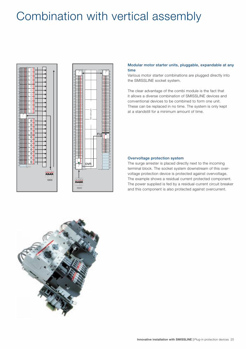
Modular motor starter units, pluggable, expandable at any timeVarious motor starter combinations are plugged directly into the SMISSLINE socket system.
The clear advantage of the combi module is the fact that it allows a diverse combination of SMISSLINE devices and conventional devices to be combined to form one unit. These can be replaced in no time. The system is only kept at a standstill for a minimum amount of time.
Overvoltage protection systemThe surge arrester is placed directly next to the incoming terminal block. The socket system downstream of this over-voltage protection device is protected against overvoltage. The example shows a residual current protected component. The power supplied is fed by a residual-current circuit breaker and this component is also protected against overcurrent.

26 Plug-in protection devices | Innovative installation with SMISSLINE
Successful in any location
Shopping centresQuick change configuration − Clearly arranged residual current protection structure − Multiple-pole devices can be placed in any position −
Industrial buildingsHigh availability − Combi module as complete motor starter unit − Clearly arranged devices and terminals −
EDP and radio installationsCentral installation monitoring −Flexible adaptation to building requirements −Permanent current available −
Office buildingsFlexibility in lighting and air-conditioning systems −Expansion options − Flexibility for system modifications −

Innovative installation with SMISSLINE | Plug-in protection devices 27
Hospitals, clinicsHigh degree of safety during maintenance and servicing −Short reaction times −Permanent current availability −
AirportsHigh degree of availability −Short reaction times −Cost effective adaptations −
TelecommunicationsInterchangeability of devices −Overvoltage-protected systems −Specifically targeted device and circuit protection −
Banks, insurance companiesQuick execution during changes in application −Various power supply options −Distribution of residual current protection −is clear and well arranged
TransportationShort time delayed residual current circuit-breakers −for long cablesOvervoltage-protection system −Fast replacement of combi module as complete motor −starter unit

Contact us
2CC
C45
1033
C02
02AustraliaABB Australia Pty Limited601 Blackburn RoadNotting Hill VIC 3168AustraliaTelephone +61 (0) 3 8544 0000Telefax +61 (0) 3 8544 0001
www.au.abb.com
BelgiumABB ELECTRO n.v.Hoge Wei, 271930 ZaventemBelgiumTelephone +32 (0) 27 18 63 11Telefax +32 (0) 27 18 66 66
www.abb.be
BrasilABB LtdaAv. dos Autonomistas, 149606020-902-Osasco-SPBrasilTelephone +55 (0) 80 00 14 91 11Telefax +55 (11) 36 88 99 77
www.abb.com.br
Czech RepublicABB s.r.o.Herspická 1361900 BrnoCzech RepublicTelephone +420 54 31 45 50 3Telefax +420 54 32 43 48 9
www.abb.cz/elsynn
DenmarkABB ASMeterbuen 332740 SkovlundeDenmarkTelephone +45 44 50 44 50Telefax +45 44 50 44 60
www.abb.dk
FinlandABB OYDomestic SalesP.O. Box 18200381 HelsinkiFinlandTelephone +358 10 22 20 00Telefax +358 10 22 22 91 3
www.abb.fi
FranceABB EntrelecDivision Commercial France300 rue des Prés SeigneursZA La Boisse – BP 9014501124 Montluel CedexFranceTelephone +33 (0) 825 38 63 55Telefax +33 (0) 825 87 09 26
www.abb.fr
Great BritainABB LimitedTower CourtFoleshill Enterprise ParkCourtaulds WayCoventryCV6 5NXEnglandTelephone +44 (0) 24 76 36 85 00Telefax +44 (0) 24 76 36 44 99
www.abb.com/lowvoltage
IrelandAsea Brown Boveri Ltd.Belgrad Road, TallaghtDublin 24IrelandTelephone +35 31 40 57 30 0Telefax +35 31 40 57 33 2
www.abb.com/lowvoltage
ItalyABB SACE S.p.A.Line Protection DevicesViale dell‘Industria, 1820010 Vittuone (MI) ItalyTelephone +39 02 90 34 1Telefax +39 02 90 34 76 09
www.abb.it
NetherlandABB b.v.Automation ProductsMarten Meesweg 53068 AV RotterdamPostbus 3013000 AH RotterdamNetherlandTelephone +31 (0) 10 40 78 91 1Telefax +31 (0) 10 40 78 09 0
www.abb.nl
NorwayABB AS Automation TechnologyProducts DivisionP.O. Box 797 Brakeroya3002 DrammenNorwayTelephone +47 32 24 80 00Telefax +47 32 24 79 34
www.abb.no
PolandABB Sp. z o.o. Automation Productsul. Zeganska 104-713 WarszawaPolandTelephone +48 22 51 64 441Telefax +48 22 51 64 444
www.abb.pl
P.R. ChinaABB (China) LtdUniversal Plaza, 10 Jiuxianqiao LuChaoyang District100016 BeijingP.R. ChinaTelephone +86 10 8456 6688Telefax +86 10 8456 9907
www.abb.com.cn
Russian FederationABB Industrial & Building Systems Ltd.30/1, bld. 2, Obrucheva St.117861 Moscow, RussiaTelephone +7 495 960 2200Telefax +7 495 960 2220
www.abb.ru/ibs
SingaporeABB Industry Pte Ltd2 Ayer Rajah CrescentSingapore 139935Telephone +65 6776 5711Telefax +65 6778 0222
www.abb.com.sg
SpainABB Automation Products, S.A.c/Torrent de l’Olla 22008012 BarcelonaSpainTelephone +34 93 48 42 21Telefax +34 93 48 42 190
www.abb.es
SwedenABB AutomationTechnologies Cewe ControlMuturgräd 2072161 VästerasSwedenTelephone +46 (0) 21 32 07 00Telefax +46 (0) 21 12 60 01
www.abb.se
SwitzerlandABB Switzerland Ltd.CMC Low Voltage ProductsFulachstrasse 150CH-8201 SchaffhausenTel. +41 58 586 41 11 Fax +41 58 586 42 22E-mail: [email protected]
www.abb.ch
UkraineABB Ltd, UkraineAutomation Products Low Voltage4, Ivana Lepse Blvd.Kiev 67, 03680UkraineTelephone +380 44 495 22 11Telefax +380 44 495 22 10
www.abb.ua
United Arab EmiratesABB Industries (L.L.C)P.O. Box 11070DubaiUnited Arab EmiratesTelephone +971 4 314 7500Telefax +971 4 340 1771
www.mena.abb.com