INFOGR: Graphics Practicals 1: XNA Tutorial · This tutorial is based on the XNA 3D Series 1...
54
2014/2015, 4th quarter INFOGR: Graphics Practicals 1: XNA Tutorial Author: Emiel Bon Based on a tutorial by Riemer Grootjans http://www.riemers.net/eng/Tutorials/XNA/Csharp/series1.php The assignment: The purpose of this assignment is to do a tutorial that takes you through the basics of 3D programming. We expect you to work through this tutorial and familiarize yourself with all the concepts and implementations provided here. The idea is to get to know 3D computer graphics from programmer’s perspective, i.e., to see how a modern 3D API works and to familiarize yourself with the anatomy of an interactive 3D graphics application. You will need to use what you learn here for the second and third practical assignment, which will be more challenging than this one. In practice this comes down to the following: When doing the tutorial, you will create an example program that performs basic 3D rendering. You should hand in your end result after working through the tutorial. This means all your source code and project files and a readme (see the Deliverables section below). Please note that this assignment is a tutorial, simply completing this tutorial will practically give you a good grade for free. This tutorial is not representative of the difficulty of the other practica. The other practica will be significantly harder and require more personal effort. Correspondingly, the weighing of your grade for this tutorial is also lower than that of the other practica. The reason for this is that there are a lot of students in this course, where some might not have much programming experience with C# and XNA yet. They should have a fair chance to catch up with the more experienced students. The more experienced students are encouraged to finish this assignment early and start working on the second assignment as soon as it becomes available. The following rules for submission apply: Your code has to compile and run on the machines in BBL 112/106/109/103/175, so if you work on other computers make sure to do a quick check there before you submit it. If this requirement isn't met, your work cannot be graded and your grade will default to 0. Please clean your solution before submitting (i.e. remove all the compiled files and intermediate output), see Appendix 1A of the Tutorial for more information. After this you can zip the solution directory and send it over. If your zip-file is multiple mega-bytes in size, then probably something went wrong (not cleaned properly). When grading, we want to get the impression that you really understand what is happening in your code, so your source files should also contain comments to explain what you think is happening. (Besides, every good program should be properly documented!) Finally, we also want to see a consistent and well readable coding style. Use indentation to indicate structure in the code for example. Don't worry about this too much, if it is readable and consistent throughout the whole project, you should be fine.
Transcript of INFOGR: Graphics Practicals 1: XNA Tutorial · This tutorial is based on the XNA 3D Series 1...

2014/2015, 4th quarter
INFOGR: Graphics
Practicals 1: XNA Tutorial Author: Emiel Bon Based on a tutorial by Riemer Grootjans http://www.riemers.net/eng/Tutorials/XNA/Csharp/series1.php
The assignment:
The purpose of this assignment is to do a tutorial that takes you through the basics of 3D programming. We expect you to work through this tutorial and familiarize yourself with all the concepts and implementations provided here. The idea is to get to know 3D computer graphics from programmer’s perspective, i.e., to see how a modern 3D API works and to familiarize yourself with the anatomy of an interactive 3D graphics application. You will need to use what you learn here for the second and third practical assignment, which will be more challenging than this one.
In practice this comes down to the following: When doing the tutorial, you will create an example program that performs basic 3D rendering. You should hand in your end result after working through the tutorial. This means all your source code and project files and a readme (see the Deliverables section below).
Please note that this assignment is a tutorial, simply completing this tutorial will practically give you a good grade for free. This tutorial is not representative of the difficulty of the other practica. The other practica will be significantly harder and require more personal effort. Correspondingly, the weighing of your grade for this tutorial is also lower than that of the other practica.
The reason for this is that there are a lot of students in this course, where some might not have much programming experience with C# and XNA yet. They should have a fair chance to catch up with the more experienced students. The more experienced students are encouraged to finish this assignment early and start working on the second assignment as soon as it becomes available.
The following rules for submission apply:
Your code has to compile and run on the machines in BBL 112/106/109/103/175, so if you work on other computers make sure to do a quick check there before you submit it. If this requirement isn't met, your work cannot be graded and your grade will default to 0.
Please clean your solution before submitting (i.e. remove all the compiled files and intermediate output), see Appendix 1A of the Tutorial for more information. After this you can zip the solution directory and send it over. If your zip-file is multiple mega-bytes in size, then probably something went wrong (not cleaned properly).
When grading, we want to get the impression that you really understand what is happening in your code, so your source files should also contain comments to explain what you think is happening. (Besides, every good program should be properly documented!)
Finally, we also want to see a consistent and well readable coding style. Use indentation to indicate structure in the code for example. Don't worry about this too much, if it is readable and consistent throughout the whole project, you should be fine.

Grading:
If you do all the above properly, you get an 8. You can also earn one extra point for each of two bonus assignments to get the perfect grade 10. The bonus assignments are:
Add some nice color to the terrain, based on values that you have present, like the height for instance.
Create a more elaborate camera system that lets you move and rotate the camera through the 3D world. For example, how about a nice implementation that uses the mouse to look around?
Deliverables:
A ZIP-file containing:
1. The contents of your (cleaned) solution directory
(see Appendix A for how to “clean your solution”)
2. The read-me (in the .txt file format)
The contents of your solution directory should contain:
(a) Your solution file (GraphicsPractical1.sln)
(b) All your source code
(c) All your project and content files
The readme file should contain:
(a) The names and student IDs of your team members.
[2-3 students; penalties for submitting with less or more team members will apply]
(b) A statement about what bonus assignments you have implemented (if any) and related information that is needed to grade them, including detailed information on your implementation.
[We will not make any wild guesses about what you might have implemented nor will we spend long times searching for special features in your code. If we can’t find and understand them easily, they will not be graded, so make sure your description and/or comments are clear.]
Just to make sure, the contents of the zip file should look like this:
/GraphicsPractical1.sln /GraphicsPractical1 /GraphicsPractical1 /GraphicsPractical1Content /readme.txt

So put the contents of your solution directory and the read-me file (in the .txt file format) directly in the root of the zip file. Note that any violation to these rules can have consequences for your grade. Also notice that the readme file should be well readable. It is part of the program that you are producing, so the rules about “consistent and clear coding style” apply to it as well.
Mode of submission:
Upload your zip file before the deadline via the SUBMIT system at http://www.cs.uu.nl/docs/submit/
Make sure to upload it to the correct entry, i.e. not the ones for late delivery if you are submitting on time (otherwise, grade deductions will still apply).
Note that we only grade the latest submitted version of your assignment, so if you upload to the late delivery entries your earlier submission will be discarded.
Deadline:
Wednesday, May 6, 2015, 23:59h
If you miss this deadline, there will be a second entry in the submit system to upload your solutions. It is open 12h longer, i.e. till May 7, 2015, 12:00 (noon). Uploading to this entry will result in a deduction of 0.5 in your grading (attention: the deduction still applies if you upload to this entry earlier!).
If you miss the second deadline as well, there will be a third entry in the submit system to upload your solutions. It is open 24h longer, i.e. till May 7, 2015, 23:59. Uploading to this entry will result in a deduction of 1.0 in your grading (attention: the deduction still applies if you upload to this entry earlier!).
If you the miss third deadline as well, contact the instructor of the course as soon as possible. Based on your reasons for the delay, he will decide if you get further reductions or if your assignment will be graded with a 0.

INFOGR 2014-2015 – Tutorial assignment © 2015 Emiel Bon, Wolfgang Huerst, Tom Rijnbeek, Jacco Bikker
Page 4 of 54
XNA Tutorial Overview
Chapter 1: Introduction
1.1 Starting an XNA 4.0 project
1.2 The Graphics Device
1.3 Performance measure
1.4 Effects
Chapter 2: Drawing
2.1 The first triangle
Chapter 3: 3D Coordinate System
3.1 World Space Coordinates
3.2 Creating the camera
3.3 Using the camera
Chapter 4: Transformations
4.1 Rotations and translations
Chapter 5: User interaction
5.1 Rotate your camera using the keyboard
Chapter 6: Example: Terrain Rendering
6.1 Terrain creation basics
6.2 Terrain creation from file
Chapter 7: Adding some depth: Lighting basics
7.1 Experimenting with Lights
7.2 The Vertex Declaration
7.3 Adding normals to our Terrain Part 1: Naive approach
Chapter 8: Optimizations using indices
8.1 Recycling vertices using indices
8.2 Adding normals to our Terrain Part 2: Better approach
8.3 Improving performance by using VertexBuffers and IndexBuffers
Bonus Assignments
Appendix

INFOGR 2014-2015 – Tutorial assignment © 2015 Emiel Bon, Wolfgang Huerst, Tom Rijnbeek, Jacco Bikker
Page 5 of 54
Chapter 1: Introduction
This tutorial is based on the XNA 3D Series 1 Tutorial by Riemer Grootjans. Its goal is to teach some of the basics of computer graphics programming. It is aimed at students who have some programming experience, preferably in an object-oriented programming language like C# or Java. The programming language used in this tutorial is C# and the computer graphics framework we use is called XNA, which is a free graphics framework built around DirectX. XNA is a wrapper for DirectX, one of the two most common low-level graphics interfaces (OpenGL and DirectX, the latter is specific to Microsoft platforms; OpenGL is very similar in its basic structure, but uses a procedural interface targeting at a wider range of platforms). Because all these products are made and provided by Microsoft, we will also use Visual Studio 2010 as the development environment on the Windows 7 platform, because it has native support for C# and XNA. Please consider this a case study; on a structural level, the things you will learn here will be very similar in most other platforms and environments (we just have to make a choice for one specific example to work with).
1.1 Starting an XNA 4.0 project
Assuming that you have Visual Studio 2010 and XNA installed, the first thing on the list is to start a project in Visual Studio. Start up Visual Studio 2010, open the File menu, hover over New and in the menu that appears select Project. In the next dialog, you choose the project template. For this tutorial, we need the Windows Game (4.0) template. This template will generate some needed code and settings for us. The code and settings will be explained shortly.
Set the project name to “GraphicsPractical1”. The name of the solution (the set of projects) will automatically be given the same name as the project, although it is possible to change it. Let's just keep the solution name and the project name the same. Leave the Create directory for solution box checked and press OK.
Visual Studio has created two small XNA projects for you, one called “GraphicsPractical1” and another called “GraphicsPractical1Content”. The former is where you place your C# code and the latter is where you place all your resources, like images and 3D models.
Before we start looking into the code, right-click on the GraphicsPractical1 project in Solution Explorer (not on the solution with the same name and not on the GraphicsPractical1Content project) and select Properties. In the XNA Game Studio tab, you can choose a Game profile: Reach or HiDef. In the room reserved for the practica, computers are equipped with DirectX 10 compatible graphics cards and can thus use the HiDef profile. On computers without support for DirectX 10 (or newer versions), the Reach profile can be used. Both provide under-the-hood optimizations for either newer or older graphics hardware, though the Reach profile has some limitations to ensure that your program works on older graphics hardware, the most apparent being that it doesn't support Shader Model 3, which you are going to use in the other practical assignments.

INFOGR 2014-2015 – Tutorial assignment © 2015 Emiel Bon, Wolfgang Huerst, Tom Rijnbeek, Jacco Bikker
Page 6 of 54
Next, in the Application tab, set the Output type from Windows Application to Console Application. This way, you get a console to which you can print (debug) messages using Console.WriteLine() alongside your main window, should you feel the need to.
All set! Let's look at the code that Visual Studio generated for us. Two C# source files were created, namely Program.cs and Game1.cs. You can find them using the Solution Explorer on the left side of your window. Program.cs is where our application starts, it uses the Main() method to create an instance of Game1, and that's all it does. The code in this file does not need to be changed. Next is Game1.cs, where, under a thick layer of comments (which are best removed once read), the structure of an XNA application can be seen:
The constructor method Game1() is called once at start up. It is used to load some variables needed by the XNA framework.
The Initialize() method is also called once on start up. This is the method where we should put our initialization code.
The LoadContent() method is used for importing media (such as images, objects and audio) as well as data related to the graphics card.
The UnloadContent() method is where you should do some cleanup before the application is terminated, although not strictly necessary.
The Update() method by default is called exactly 60 times per second. Here we will put the code that needs to be updated throughout the lifetime of our program, such as the code that reads the keyboard and updates the geometry of our scene.
As often as your computer (and especially your graphics card) allows, the Draw() method is called. This is where we should put the code that actually draws our 3D scene to the screen.
There is no code to open a window, this is done automatically. Also, you do not need any code to keep the application running. When you press F5 to enter debug mode and run this code, you will see a window with a nice blue background.
Before we go any further, let's discuss the structure that our application is going to have in the end. We will implement classes that represent a camera, a height map, a terrain and a struct (see Appendix 2A) called VertexPositionColorNormal. Also, included in the assignment files is a FrameRateCounter class, which keeps track of how many frames your application draws per second. This can be used as a crude but effective tool to measure the performance of your application and using this, you can clearly see the benefit of certain techniques used in this tutorial.
One last word of advice, if you want to know more about the built in classes that XNA provides (for instance, what namespace you need to use before you can use it!), you should look them up on Microsoft's information database MSDN. Just type something like “XNA <class name or method name> MSDN” in Google and you should find exactly what you need.
1.2 The Graphics Device
Let's get started.
One very important (if not the most important) thing when doing graphics programming is the graphics card. XNA provides an object that gives you direct access to the graphics hardware in your computer. This object is called GraphicsDevice. The Microsoft.Xna.Framework.Game class, which is the super class of our Game1 class, has a property (see Appendix 2B) to access the GraphicsDevice,

INFOGR 2014-2015 – Tutorial assignment © 2015 Emiel Bon, Wolfgang Huerst, Tom Rijnbeek, Jacco Bikker
Page 7 of 54
conveniently called GraphicsDevice.
We will do some initialization, and where better to do that then in the Initialize() method. We will set some properties for the window, and end with the call to base.Initialize():
this.graphics.PreferredBackBufferWidth = 800;
this.graphics.PreferredBackBufferHeight = 600;
this.graphics.IsFullScreen = false;
this.graphics.SynchronizeWithVerticalRetrace = false;
this.graphics.ApplyChanges();
this.IsFixedTimeStep = false;
The back buffer contains what will be drawn on the screen. All the instructions you give your XNA program to draw something on the screen, actually draw to this hidden canvas first. When all the instructions are processed, the content of the window is replaced by this canvas, which makes it visible on the screen. This is called double buffering, and it is used to prevent flickering of the screen.
The window will automatically adjust to the size of the back buffer. Also we set that we don't want the window to fill the whole screen.
Note: Some books use the term frame buffer instead of back buffer, but this term is used by both DirectX and OpenGL to describe different things. For this tutorial, you can consider the terms back buffer and frame buffer interchangeable.
The SynchronizeWithVerticalRetrace property, when set to true, forces the Game class to synchronize the calls to the Draw method with the refresh rate of the monitor (this is probably a left-over from CRT times…). We set it to false, we want the Draw method to be called as often as possible, so we can clearly see the impact on performance of things we draw. The changes have to be committed to the hardware and this is not done automatically, so we call the this.graphics.ApplyChanges() method to do this explicitly, so the graphics card knows that we made some changes.
Finally, we set a very tricky property, called IsFixedTimeStep, to false. If set to true, the following happens: the Update() method by default gets called exactly 60 times per second (you can also change this to 120 times for instance). After that, XNA immediately does a call to Draw(). If Update() + Draw() take less than 1/60 of a second, the game remains idle until it is time for another call to Update(). If it takes more than 1/60 of a second, Draw() isn't called until the game catches up with itself. Bottom line, the Draw() method gets called as often as the Update() method, or less.
When we set this property to false, the Game class does nothing this elaborate for us and just calls Update() as often as possible, always followed by a call to Draw(). For the above mentioned reason

INFOGR 2014-2015 – Tutorial assignment © 2015 Emiel Bon, Wolfgang Huerst, Tom Rijnbeek, Jacco Bikker
Page 8 of 54
of measuring performance, this is more desirable.
When you compile and run this code, the result should look like this:
1.3 Performance measure
During the development of our application, we want to keep track of the performance. As said earlier, a crude but effective way to measure this is using the number frames that are drawn in each second. A very simple way to display this is by updating the title of the window with this information. Included in the assignment's files is a class called FrameRateCounter that does this for you. Add it to your GraphicsPractical1 project by right-clicking on the project, hover over Add and choose Existing Item. Browse for the FrameRateCounter.cs file and press the Add button.
Now lets put it to work. First add this variable to the top of your Game1 class:
private FrameRateCounter frameRateCounter;
Fill this variable in the constructor method of the Game1 class:
this.frameRateCounter = new FrameRateCounter(this);
this.Components.Add(this.frameRateCounter);
The FrameRateCounter wants a Game class as a parameter. The second line adds the

INFOGR 2014-2015 – Tutorial assignment © 2015 Emiel Bon, Wolfgang Huerst, Tom Rijnbeek, Jacco Bikker
Page 9 of 54
FrameRateCounter to this Game's list of components, which means that at the end of the Initialize(), Update() and Draw() method, the corresponding method is also called on all it's components, which is very convenient for a frame rate counter. Finally, add this line to the Update() method of the Game1 class:
this.Window.Title = "Graphics Tutorial | FPS: " + this.frameRateCounter.FrameRate;
This line updates the window's title, so it shows the text “Graphics Tutorial”, a vertical line, the word “FPS: ” (abbreviation for Frames Per Second) and finally the current frame rate, obtained from the frame rate counter. The result should look something like this:
1.4 Effects
The way XNA lets you interact with the graphics hardware looks very similar to the DirectX 9 API. However, one of the main differences between DirectX 9 and XNA is that we need an effect for everything we draw. So what exactly is an effect?
In 3D programming, all objects are represented using simple primitives, i.e. basic geometric objects. In general, these are just triangles. Even spheres can be represented (more precisely, approximated) using triangles, if you use enough of them. An effect is a piece of code that instructs your hardware (the graphics card) how it should display these triangles. The sequence of operations that is done to put these triangles on the screen is generally referred to as the graphics pipeline or rendering pipeline.

INFOGR 2014-2015 – Tutorial assignment © 2015 Emiel Bon, Wolfgang Huerst, Tom Rijnbeek, Jacco Bikker
Page 10 of 54
Back in the old days, graphics were processed by the so called fixed-function pipeline. Here you would pass some descriptions of 3D triangles in one end of the “pipeline”, and at the other end they would come out, rasterized to the screen, with appropriate shading (surface colors varying due to lighting) applied. The influence of the programmer in the way triangles were processed was limited to selecting from a number of fixed shading models and setting up a few parameters for those.
At present, programmers can exert much more influence, by use of the programmable rendering pipeline. A set of software instructions, called a shader, written by the programmer can be used to program the Graphics Processing Unit (GPU), which is a processor on the graphics card – pretty much like a CPU, but optimized for processing and displaying 3D graphics. XNA does not use shaders directly like DirectX, but uses a so called effect, which is basically a bundle of shaders combined with state. You don't need to worry about what they are right now, just remember that effects enable you to use shaders more easily.
We will not write shaders/effects ourselves just yet. Instead, we will use a default XNA effect called BasicEffect, which emulates the simple way of processing of the fixed-function pipeline. We have to explicitly use an effect, because even if we want to draw only one very simple triangle, XNA needs to be told how it should do this exactly.
Let us create this effect by first defining a variable for it. Add this line at the top of your Game1 class:
private BasicEffect effect;
Next we fill this variable in the LoadContent() method:
this.effect = new BasicEffect(this.GraphicsDevice);
With all the necessary variables loaded, we can concentrate on the Draw() method. You’ll notice the first line starts with a Clear command. This line clears the back buffer of our window to a specified color. Let’s set this to DarkSlateBlue, just for fun:
this.GraphicsDevice.Clear(Color.DarkSlateBlue);
XNA uses a back buffer to draw to, instead of drawing directly to the window. This is called double buffering. At the end of the Draw() method, the contents of the back buffer are drawn on the screen in one time. This way, the screen will not flicker as it would when we would draw each separate part of our scene directly to the screen.
Running this code will already give you the image you see below, but we should first add some additional code. An effect has one or more techniques, and when using a custom effect (e.g. one you have written yourself), we need to specify which technique we want to use for rendering. BasicEffect

INFOGR 2014-2015 – Tutorial assignment © 2015 Emiel Bon, Wolfgang Huerst, Tom Rijnbeek, Jacco Bikker
Page 11 of 54
however, has only one technique and automatically decides for us that we want to use this technique for rendering, so we won't have to tell it which technique to use explicitly. We will immediately activate our effect, so next chapter we are ready to render something to the screen!
A technique can be made up of one or multiple passes, so we need to iterate through them. The idea behind multiple passes is that you would want for instance to draw something using certain settings (specified in the shader) in the first pass, and in a subsequent pass apply to that result some sort of post-processing effect with another shader. Another possibility is that you would want to first draw something, then another thing and blend these two things together.
Add this code to the Draw() method, below the code you just entered:
foreach (EffectPass pass in this.effect.CurrentTechnique.Passes)
{
pass.Apply();
}
All your drawing code must be put after your call to pass.Apply().
Finally, we’re through the initialization part! If you’re not yet 100% clear on effects and techniques, there’s no need to worry. With all of this code set up, we’re finally ready to start drawing things on the screen, which is what we will do in next chapter.

INFOGR 2014-2015 – Tutorial assignment © 2015 Emiel Bon, Wolfgang Huerst, Tom Rijnbeek, Jacco Bikker
Page 12 of 54
Chapter 2: Drawing
This chapter will cover the basics of drawing.
2.1 The first triangle
First a few things you should know about. Every object drawn in 3D is drawn using triangles. Surprisingly enough, a triangle is defined by 3 points. Every point is defined by a vector, specifying the x-, y- and z-coordinates of the point. However, just knowing the coordinates of a point might not be enough. For example, you might want to define a color for the given point as well. This is where a vertex (pl. vertices) comes in: it is the list of properties of a given point, including the position, color and so on.
XNA has a structure that fits perfectly to hold our vertex information: the VertexPositionColor struct. A vertex of the VertexPositionColor type can hold a position and a color, which is perfect to begin with. To define a triangle, we’ll need 3 of those vertices, which we will store in an array. So let’s declare this variable at the top of our Game1 class:
private VertexPositionColor[] vertices;
Next, we will add a small method to our code, setupVertices(), which will fill this array with 3 vertices:
private void setupVertices()
{
this.vertices = new VertexPositionColor[3];
this.vertices[0].Position = new Vector3(-0.5f, -0.5f, 0f);
this.vertices[0].Color = Color.Red;
this.vertices[1].Position = new Vector3(0f, 0.5f, 0f);
this.vertices[1].Color = Color.Yellow;
this.vertices[2].Position = new Vector3(0.5f, -0.5f, 0f);
this.vertices[2].Color = Color.Green;
}
The array is initialized to hold 3 vertices, after which it is filled. For now, we’re using coordinates in screen-space, i.e coordinates that are relative to the screen: the (0, 0) point is defined in XNA as the middle of our screen, the (-1, -1) point is bottom-left and the (1, 1) point top-right. The z-coordinate has no meaning in screen-space, so we set it to 0. So in the example above, the first point is halfway to the bottom left of the window, and the second point is halfway to the top in the middle of our screen. As they are not really 3D coordinates, they don’t need to be transformed to 2D coordinates.
The 'f' behind some of the numbers indicates the values are floats, the format of preference when

INFOGR 2014-2015 – Tutorial assignment © 2015 Emiel Bon, Wolfgang Huerst, Tom Rijnbeek, Jacco Bikker
Page 13 of 54
working with XNA. We set each of the vertices to different colors. We still need to call this setupVertices() method, do this at the end of the LoadContent() method:
this.setupVertices();
All we have to do now is tell the device to draw the triangle! Go to our Draw() method, where we should draw the triangle after the call to pass.Apply():
this.GraphicsDevice.DrawUserPrimitives(PrimitiveType.TriangleList, this.vertices, 0, 1,
VertexPositionColor.VertexDeclaration);
This line actually tells our graphics card to draw the triangle: we want to draw 1 triangle from the vertices array, starting at vertex 0. TriangleList means that our vertices array contains a list of triangles (in our case, a list of only 1 triangle). The TriangleList takes every subsequent group of three vertices from the array and considers this to be a triangle. If you would want to draw 4 triangles, you would need an array of 12 vertices. Another possibility is to use a TriangleStrip, which takes every group of four vertices from the array and makes two joined triangles that share the second and third vertex. For non-indexed drawing (which is what we have been doing so far), the TriangleStrip can perform a lot faster, but is only useful to draw triangles that are connected to each other in a very specific way. Later in this tutorial we switch to indexed drawing. The last argument specifies the vertex declaration, which is quite important. We have stored the position and color data for 3 vertices inside an array. When we instruct XNA to render a triangle based on this data, XNA will put all this data in a byte stream and send it over to the graphics card. Our graphics card receives the byte stream, but doesn’t know what’s in there! That’s where the vertex declaration comes in: this object tells the graphics device what kind of vertices it can expect. The vertex declaration is very important, as you will always need it before you can render any triangle to the screen. By specifying the VertexPositionColor.VertexDeclaration, we inform the graphics card that there are vertices coming its way that contain position and color data. We’ll see how we can create our own vertex types later on in this tutorial.
One last thing. By default, the BasicEffect does nothing with the Color data in the VertexPositionColor struct, so running the application now would show a blue window with a white triangle. To use colors, we add the following code to LoadContent():
this.effect.VertexColorEnabled = true;
Running this code should give you this result:

INFOGR 2014-2015 – Tutorial assignment © 2015 Emiel Bon, Wolfgang Huerst, Tom Rijnbeek, Jacco Bikker
Page 14 of 54

INFOGR 2014-2015 – Tutorial assignment © 2015 Emiel Bon, Wolfgang Huerst, Tom Rijnbeek, Jacco Bikker
Page 15 of 54
Chapter 3: 3D Coordinate System
3.1 World Space Coordinates
Last chapter we drew a triangle, using pre-transformed coordinates. These coordinates allow you to directly specify their position on the screen. However, you will usually use the untransformed coordinates, the so called world space coordinates, which we specify in 3D coordinates. These allow you to create a whole scene using 3D coordinates that are used like coordinates in the real world, and, also very important, to position a camera through which the user will look at the scene. Let’s start by redefining our triangle coordinates in 3D World space. Replace the code in our setupVertices() method with this code:
private void setupVertices()
{
this.vertices = new VertexPositionColor[3];
this.vertices[0].Position = new Vector3(0f, 0f, 0f);
this.vertices[0].Color = Color.Red;
this.vertices[1].Position = new Vector3(10f, 10f, 0f);
this.vertices[1].Color = Color.Yellow;
this.vertices[2].Position = new Vector3(10f, 0f, -5f);
this.vertices[2].Color = Color.Green;
}
As you can see, from here on we’ll be using the z-coordinate as well. Let's run this code. Very nice, our triangle has disappeared. Why's that? Easy, because we are no longer using pre-transformed screen coordinates (where the x and y coordinate should be in the [-1, 1] region) and because we haven't told XNA yet where to position the camera in the 3D World, and where to look at!
3.2 Creating the camera
We will first create a new class that will represent our camera. Right-click the GraphicsPractical1 project, hover over Add and click New Item, or simply press Ctrl+Shift+A, and select Class. In the field called Name, write “Camera” (without the quotes) and press the Add button. The file Camera.cs should be created and opened in the Code window, if not, double-click Camera.cs in Solution Explorer.
To position our camera, we need to define some matrices. Stop!! matrices?!?
First a small word about matrices. We define our points in 3D space. Because our screen is 2D, it is only logical that our 3D points somehow need to be “transformed” to 2D space. This is done by

INFOGR 2014-2015 – Tutorial assignment © 2015 Emiel Bon, Wolfgang Huerst, Tom Rijnbeek, Jacco Bikker
Page 16 of 54
multiplying our 3D positions with a matrix. So in short, you should see a matrix simply as a mathematical element (a black box for now) that holds a certain transformation. If you multiply a 3D (or world-space) position with such a matrix, you get the transformed (or screen-space) position. You will learn all about matrices in the lectures.
Because there are a lot of properties that need to be defined when transforming our points from 3D world-space to our 2D screen, this transformation is split in 2 steps, so we get 2 matrices. First add these variables to the top of your Camera class:
private Matrix viewMatrix;
private Matrix projectionMatrix;
You may have to write using Microsoft.Xna.Framework; to be able to use the Matrix class. The view matrix will be created from three vectors, called the up-, eye-, and focus vector respectively. For more information on those, see Chapter 7 on Viewing of the Fundamentals of Computer Graphics book. So add the following variables to the top of the class as well:
private Vector3 up;
private Vector3 eye;
private Vector3 focus;
These variables are useless to us if we don't fill them with something useful, so let's do that in the constructor method.
public Camera(Vector3 camEye, Vector3 camFocus, Vector3 camUp, float aspectRatio = 4.0f / 3.0f)
{
this.up = camUp;
this.eye = camEye;
this.focus = camFocus;
}
The first argument passed to the constructor will represent the camera's eye, i.e. the point from which it is looking. The second argument, focus, is the point the camera is looking at. The final argument is the view aspect ratio, the ratio between the width and height of our window. In our case of a 800x600 window this will roughly be equal to 1.3333, but this will be different for other resolutions, so we let the user of our Camera class choose this by adding a fourth parameter to the constructor.

INFOGR 2014-2015 – Tutorial assignment © 2015 Emiel Bon, Wolfgang Huerst, Tom Rijnbeek, Jacco Bikker
Page 17 of 54
The next step is to use these parameters to create the right matrices. As we are going to have the recalculate the view matrix on several occasions, let’s add a method for that first:
private void updateViewMatrix()
{
this.viewMatrix = Matrix.CreateLookAt(this.eye, this.focus, this.up);
}
This method creates the view matrix, a matrix that stores the position and orientation of the camera, through which we look at the scene. The first argument defines the position of the camera. The next parameter sets the target point the camera is looking at. At this point, we have defined the viewing axis, also called the gaze vector of our camera, but we can still rotate our camera around this axis. So we still need to define which vector will be considered as “up”.
The other matrix will just be calculated once, so we can go ahead and add the following lines to the constructor of the Camera class.
this.updateViewMatrix();
this.projectionMatrix = Matrix.CreatePerspectiveFieldOfView(MathHelper.PiOver4,
aspectRatio, 1.0f, 300.0f);
The first line calls the method we made before, which calculates the view matrix. The second line creates the projection matrix, a matrix which stores how the camera looks at the scene, much like defining the lens if you will. More formally, it is the matrix that describes how the points from the 3D world, after having been transformed to camera coordinates, should be projected onto the view plane. The lectures will cover all of this, but if you want more information now, read Chapter 7 on Viewing in the Fundamentals of Computer Graphics book.
The first argument sets the view angle, 45 degrees in our case. Then we set the aspect ratio which we have discussed before. The last parameters for the projection matrix define the view range. Any object closer to the camera than 1.0f will not be drawn. Any object further away than 300.0f won't be drawn either. These distances are called the near- and the far clipping planes, since all objects not between these planes will be clipped (= not drawn). While we're at it, let's add some properties for the matrices:
public Matrix ViewMatrix
{
get { return this.viewMatrix; }
}
public Matrix ProjectionMatrix
{

INFOGR 2014-2015 – Tutorial assignment © 2015 Emiel Bon, Wolfgang Huerst, Tom Rijnbeek, Jacco Bikker
Page 18 of 54
get { return this.projectionMatrix; }
}
These matrices have no set-function, because the projection matrix, once set, probably never has to be changed and the view matrix only depends on the eye and focus vector, so it makes more sense to adjust the view matrix by changing those properties. However, the view matrix has to be recalculated each time the eye- or focus vector changes, and that is where the properties come in handy. Let's create properties for the eye and focus vector, so they will be easy to access from outside the Camera class:
public Vector3 Eye
{
get { return this.eye; }
set { this.eye = value; this.updateViewMatrix(); }
}
public Vector3 Focus
{
get { return this.focus; }
set { this.focus = value; this.updateViewMatrix(); }
}
Now, each time the eye- or focus vector changes, the view matrix will be updated accordingly.
3.3 Using the camera
Reopen Game1.cs in the Code window. Create a variable called “camera” of type Camera at the top of the Game1 class:
private Camera camera;
Fill this variable in the LoadContent() method, let the camera's eye be positioned 50 units along the positive z-axis and let it look at the 3D-origin (0,0,0). In our case, we choose the positive y-axis as the up vector (the up vector doesn't necessarily have to be perpendicular to the gaze vector, as long as it's not aligned with it). You can leave the aspect ratio argument out, because the default value is the aspect ratio we want for our 800x600 window.

INFOGR 2014-2015 – Tutorial assignment © 2015 Emiel Bon, Wolfgang Huerst, Tom Rijnbeek, Jacco Bikker
Page 19 of 54
this.camera = new Camera(new Vector3(0, 0, 50), new Vector3(0, 0, 0),
new Vector3(0, 1, 0));
Now that we have these camera matrices, we need to pass it to our effect, where they will be combined. This is done by the next lines of code, which we need to add to our Draw() method, just above the foreach loop:
this.effect.Projection = this.camera.ProjectionMatrix;
this.effect.View = this.camera.ViewMatrix;
this.effect.World = Matrix.Identity;
The third line sets another parameter, which is discussed in the next chapter. The assigned value of that parameter is called the identity matrix or unit matrix.
Remark: the identity matrix is a special matrix, with the property that when you multiply this by another matrix or vector, nothing happens. So 𝐴 ∙ 𝐼 = 𝐴 and 𝐼 ∙ 𝐴 = 𝐴, where 𝐼 is the identity matrix and 𝐴 is some other matrix or vector.
Now run the code. You should see the image below: a triangle, of which the bottom-right corner is not exactly below the top-right corner. This is because you have assigned the bottom-right corner a negative Z coordinate, positioning it a bit further away from the camera than the other corners.

INFOGR 2014-2015 – Tutorial assignment © 2015 Emiel Bon, Wolfgang Huerst, Tom Rijnbeek, Jacco Bikker
Page 20 of 54
One important thing you should notice before you start experimenting: you'll see the green corner of the triangle is on the right side of the window, which seems normal because you defined it on the positive x-axis. So, if you would position your camera on the negative z-axis:
this.camera = new Camera(new Vector3(0, 0, -50), new Vector3(0, 0, 0),
new Vector3(0, 1, 0));
you would expect to see the green point in the left half of the window. Try to run this now. This might not be exactly what you expected. Something very important has happened. XNA only draws triangles that are facing the camera. XNA by default specifies that the positions of the vertices of triangles facing the camera should be defined clockwise relative to the camera. If you position the camera on the negative z-axis, the corner points of the triangle in our vertices array will be defined counter-clockwise relative to the camera, and thus will not be drawn! The triangle will be designated as a back facing triangle, and removal of these triangles is called back face culling. Culling can greatly improve performance, as it can reduce the number of triangles drawn. However, when designing an application, it’s better to turn culling off by putting these lines of code in the beginning of your Draw() method:
this.GraphicsDevice.RasterizerState = new RasterizerState
{
CullMode = CullMode.None
};
This piece of code uses a special C# inline notation used to directly assign values to accessible variables in a class, as if it were done by its constructor method. It is equivalent to, but obviously much shorter and more readable than the following:
RasterizerState rs = new RasterizerState();
rs.CullMode = CullMode.None;
this.GraphicsDevice.RasterizerState = rs;
This rasterizer state will simply draw all triangles, even those not facing the camera. You should note that this should never be done in a final product, because it slows down the drawing process, as all triangles will be drawn, even those not facing the camera (except for some cases where you intend to achieve this effect). Now put the camera back to the positive part of the z-axis.

INFOGR 2014-2015 – Tutorial assignment © 2015 Emiel Bon, Wolfgang Huerst, Tom Rijnbeek, Jacco Bikker
Page 21 of 54
Chapter 4: Transformations
4.1 Rotations and translations
In this chapter we will make our triangle spin round. Since we are using world space coordinates, this is very easy to do. Let's first add a variable angle to our class to store the current rotation angle. Just add this one to your variables.
private float angle;
Now, we want to increase the angle over time. The Update() method is an excellent place to put this code. We could increase the angle by 0.05 every frame like this:
this.angle += 0.05f;
However, because we said the Update() method should be called as often as possible, we do not know exactly how often it is called per second, but we do know that it is quite a lot. We want our triangle to rotate with a constant speed, independent of the amount of update calls per second, so that is why we are going to use the GameTime parameter of the Update() method. The GameTime object has a property that contains how much time has passed since the previous call to Update(). We will use this property to our advantage. At the beginning of the Update() method, write the following line that will extract the amount of seconds passed since the last update call:
float timeStep = (float) gameTime.ElapsedGameTime.TotalSeconds;
Now, instead of adding a fixed value every frame, we increment the angle depending on the amount of passed time. To do this, we add this line in the Update() method after the line that calculates the timestep:
this.angle += timeStep * 3.0f;
With our angle increasing automatically, all we have to do is to rotate the world coordinates. This is done using transformation matrices. Luckily, all you have to do is specify the rotation axis and the rotation angle. All the rest is done by XNA!
The rotation is stored in what is called the World matrix. In your Draw() method, replace the line where you set your effect's World property with this code:

INFOGR 2014-2015 – Tutorial assignment © 2015 Emiel Bon, Wolfgang Huerst, Tom Rijnbeek, Jacco Bikker
Page 22 of 54
Matrix rotation = Matrix.CreateRotationY(this.angle);
this.effect.World = rotation;
The first line creates our rotation matrix, which holds a rotation around the y-axis. The second line passes this to the effect as the World matrix, which it needs to perform its job. From now on, everything we draw will be rotated along the y-axis by the amount currently stored in angle.
When you run the application now, you will see that your triangle is spinning with a constant speed around the 3D origin (0,0,0). This is of course because the y-axis runs through this point, so the (0,0,0) point is the only point of our triangle that remains the same. Now imagine we would like to spin it through the center of the triangle. One possibility is to redefine the triangle so the (0,0,0) would be in the center of our triangle. The better solution would be to first move (= translate) the triangle a bit to the left and down, and then rotate it. To do this, simply first multiply your World matrix with a translation matrix:
Matrix translation = Matrix.CreateTranslation(-20.0f / 3.0f, -10.0f / 3.0f, 0);
Matrix rotation = Matrix.CreateRotationY(this.angle);
this.effect.World = translation * rotation;
This will move the triangle so its center point is in the (0,0,0) 3D world origin. Next, our triangle is rotated around this point, along the y-axis, giving us the desired result.
Note the order of transformations. Go ahead and place the translation AFTER the rotation. You will see a triangle rotating around one point, moved to the left and below. This is because in matrix multiplications 𝐴 ∙ 𝐵 is NOT the same as 𝐵 ∙ 𝐴.
You can easily change the code to make the triangle rotate around the x- or z-axis. Remember that one point of our triangle has a z-coordinate of -5, which explains why the triangle seems to rotate asymmetrically sometimes. A bit more complex is the Matrix.CreateFromAxisAngle() method, where you can specify your own custom rotation axis :
Vector3 rotAxis = new Vector3(3 * this.angle, this.angle, 2 * this.angle);
rotAxis.Normalize();
Matrix translation = Matrix.CreateTranslation(-20.0f / 3.0f, -10.0f / 3.0f, 0);
Matrix rotation = Matrix.CreateFromAxisAngle(rotAxis, this.angle);
this.effect.World = translation * rotation;

INFOGR 2014-2015 – Tutorial assignment © 2015 Emiel Bon, Wolfgang Huerst, Tom Rijnbeek, Jacco Bikker
Page 23 of 54
This will make our triangle spin around an ever changing axis. The first line defines this axis, which is changed every frame as it depends on the angle variable. The second line normalizes this axis, which is needed to make CreateFromAxisAngle() work properly. Normalize() changes the coordinates of the vector, so the distance between the vector and the (0, 0, 0) point is exactly 1, or in other words, the length of the vector is equal to 1.

INFOGR 2014-2015 – Tutorial assignment © 2015 Emiel Bon, Wolfgang Huerst, Tom Rijnbeek, Jacco Bikker
Page 24 of 54
Chapter 5: User Interaction
5.1 Rotate your camera using the keyboard
Using XNA, it is very easy to read in the current state of your keyboard. The correct libraries, Microsoft.Xna.Framework.Input, are already linked to by default when you’ve started your XNA project, so we can immediately move on to the code that reads in the keyboard input.
First set the World matrix back to the identity matrix, and remove all the other transformation code:
this.effect.Projection = this.camera.ProjectionMatrix;
this.effect.View = this.camera.ViewMatrix;
this.effect.World = Matrix.Identity;
Replace the line that updates your angle with the following piece of code in your Update() method:
float deltaAngle = 0;
KeyboardState kbState = Keyboard.GetState();
if (kbState.IsKeyDown(Keys.Left))
deltaAngle += -3 * timeStep;
if (kbState.IsKeyDown(Keys.Right))
deltaAngle += 3 * timeStep;
if (deltaAngle != 0)
this.camera.Eye = Vector3.Transform(this.camera.Eye, Matrix.CreateRotationY(deltaAn-gle));
Here you put the current state of the keyboard in a variable kbState. Using this variable, you can immediately read out which keys are currently being pressed. When the user presses the left or right key, the value of the deltaAngle variable will be adjusted.
We use the value of deltaAngle to transform (rotate around the y-axis) the eye position of our camera by a small amount (or not at all, if no key is pressed) around the 3D origin. Notice though that this approach in its current state only works when the focus point is (0,0,0). We do the check for deltaAngle's value being unequal to 0, so that the view matrix won't be unnecessarily recalculated.
When you run the code, you can rotate your camera simply by pressing the left and right buttons!

INFOGR 2014-2015 – Tutorial assignment © 2015 Emiel Bon, Wolfgang Huerst, Tom Rijnbeek, Jacco Bikker
Page 25 of 54
Chapter 6: Example: Terrain Rendering
In this chapter, we will create a more complex model, namely: a terrain model. It will consist of more triangles than we have dealt with so far. Initially, we will implement this model using the most naive approach. Then we will give the terrain some depth by doing lighting calculations on it. Coincidentally, the naive way of creating a terrain model is very suitable for demonstrating a simple but suboptimal way of doing lighting calculations. In the chapter after that, we will optimize our model by using so called indices (more on those later) and this method, as it turns out, is very good for demonstrating a better way of lighting the terrain.
6.1 Terrain creation basics
Before we start on the terrain, we should do a little cleanup. Remove the setupVertices() method from the Game1 class, as well as the vertices member variable. They will return somewhere else later, so we don't need them here anymore. We will need something new, called height data, which will describe our terrain. Add the following line to the top of the Game1 class:
private float[,] heightData;
For now, use this method to fill the array :
private void loadHeightData()
{
this.heightData = new float[4, 3];
this.heightData[0, 0] = 0;
this.heightData[1, 0] = 0;
this.heightData[2, 0] = 0;
this.heightData[3, 0] = 0;
this.heightData[0, 1] = 0.5f;
this.heightData[1, 1] = 0;
this.heightData[2, 1] = -1.0f;
this.heightData[3, 1] = 0.2f;
this.heightData[0, 2] = 1.0f;
this.heightData[1, 2] = 1.2f;
this.heightData[2, 2] = 0.8f;
this.heightData[3, 2] = 0;
}

INFOGR 2014-2015 – Tutorial assignment © 2015 Emiel Bon, Wolfgang Huerst, Tom Rijnbeek, Jacco Bikker
Page 26 of 54
Don’t forget to call it from within our LoadContent() method. Also set one more property for the rasterizer state in the Draw() method of the Game1 class:
this.GraphicsDevice.RasterizerState = new RasterizerState
{
CullMode = CullMode.None,
FillMode = FillMode.WireFrame
};
This tells the graphics card to only draw the wireframes of the triangles.
Now let's work on the terrain. Let’s start small, by connecting 4x3 specified points. We will make our engine dynamic, so that in the next chapter we can easily load a much larger number of points. Let's put all the stuff related to the terrain in a separate class. Create a new class and name it “Terrain”. First add the following variables to the top of the class:
private int width;
private int height;
private VertexPositionColor[] vertices;
You will have to write using using Microsoft.Xna.Framework.Graphics; to be able to use VertexPositionColor here. Add properties with only a get function for the width and height, we want to use them from outside this class, but not be able to change them because the size should depend on the data:
public int Width
{
get { return this.width; }
}
public int Height
{
get { return this.height; }
}

INFOGR 2014-2015 – Tutorial assignment © 2015 Emiel Bon, Wolfgang Huerst, Tom Rijnbeek, Jacco Bikker
Page 27 of 54
Now we will set up a method that sets up the vertices for us. We will assume the points are equidistant. So the only thing we don't know about our points is the height, or the y-coordinate. Let’s assume the y-coordinate is 0 for now and put the following method in your Terrain class.
private VertexPositionColor[] loadVertices()
{
VertexPositionColor[] vertices = new VertexPositionColor[this.width * this.height];
for (int x = 0; x < this.width; x++)
for (int y = 0; y < this.height; y++)
{
int v = x + y * this.width;
vertices[v].Position = new Vector3(x, 0, -y);
vertices[v].Color = Color.White;
}
return vertices;
}
Nothing magical is going on here, you simply define your 12 points, give them a white color and put them in an array, and at the end you return this array of points. Note that the terrain will grow into the positive X direction (right) and into the negative Z direction (forward).

INFOGR 2014-2015 – Tutorial assignment © 2015 Emiel Bon, Wolfgang Huerst, Tom Rijnbeek, Jacco Bikker
Page 28 of 54
Now follows a more difficult part: defining the triangles to connect the 12 vertices. The best way to
do this is by creating two sets of vertices that form a triangle for each square:
We'll start by defining the set of triangles drawn in solid lines. To do this, add the method setupVertices() method to the Terrain class like this:
private void setupVertices(VertexPositionColor[] heightDataVertices)
{
this.vertices = new VertexPositionColor[(this.width - 1) * (this.height - 1) * 3];
int counter = 0;
for (int x = 0; x < this.width - 1; x++)
for (int y = 0; y < this.height - 1; y++)
{
int lowerLeft = x + y * this.width;
int lowerRight = (x + 1) + y * this.width;
int topLeft = x + (y + 1) * this.width;
int topRight = (x + 1) + (y + 1) * this.width;
this.vertices[counter++] = heightDataVertices[topLeft];
this.vertices[counter++] = heightDataVertices[lowerRight];
this.vertices[counter++] = heightDataVertices[lowerLeft];
}
}
Remember that width and height are the horizontal and vertical number of vertices in the terrain. The first line creates an array that is capable of storing exactly enough vertices to create a triangle for every square in our heightmap.
INFOGR 2014-2015 – Tutorial assignment © 2015 Emiel Bon, Wolfgang Huerst, Tom Rijnbeek, Jacco Bikker
Page 29 of 54
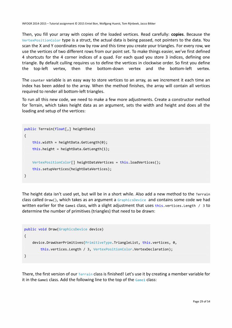
Then, you fill your array with copies of the loaded vertices. Read carefully: copies. Because the VertexPositionColor type is a struct, the actual data is being passed, not pointers to the data. You scan the X and Y coordinates row by row and this time you create your triangles. For every row, we use the vertices of two different rows from our point set. To make things easier, we’ve first defined 4 shortcuts for the 4 corner indices of a quad. For each quad you store 3 indices, defining one triangle. By default culling requires us to define the vertices in clockwise order. So first you define the top-left vertex, then the bottom-down vertex and the bottom-left vertex. The counter variable is an easy way to store vertices to an array, as we increment it each time an index has been added to the array. When the method finishes, the array will contain all vertices required to render all bottom-left triangles.
To run all this new code, we need to make a few more adjustments. Create a constructor method for Terrain, which takes height data as an argument, sets the width and height and does all the loading and setup of the vertices:
public Terrain(float[,] heightData)
{
this.width = heightData.GetLength(0);
this.height = heightData.GetLength(1);
VertexPositionColor[] heightDataVertices = this.loadVertices();
this.setupVertices(heightDataVertices);
}
The height data isn't used yet, but will be in a short while. Also add a new method to the Terrain class called Draw(), which takes as an argument a GraphicsDevice and contains some code we had written earlier for the Game1 class, with a slight adjustment that uses this.vertices.Length / 3 to determine the number of primitives (triangles) that need to be drawn:
public void Draw(GraphicsDevice device)
{
device.DrawUserPrimitives(PrimitiveType.TriangleList, this.vertices, 0,
this.vertices.Length / 3, VertexPositionColor.VertexDeclaration);
}
There, the first version of our Terrain class is finished! Let's use it by creating a member variable for it in the Game1 class. Add the following line to the top of the Game1 class:

INFOGR 2014-2015 – Tutorial assignment © 2015 Emiel Bon, Wolfgang Huerst, Tom Rijnbeek, Jacco Bikker
Page 30 of 54
private Terrain terrain;
Fill this variable in the LoadContent() method, after the call to loadHeightData():
this.terrain = new Terrain(this.heightData);
And replace the this.GraphicsDevice.DrawUserPrimitives() line in the Draw() method of Game1 with:
this.terrain.Draw(this.GraphicsDevice);
If we would run the code now, we wouldn't see anything. That's because our camera isn't positioned correctly. The vertices all lie flat on the x,z-plane, so we want to look at them from directly above, which is from the positive y-axis. When we do this, we have to adjust the up vector as well, because that can't be aligned with the gaze vector (the vector from the eye to the focus point). We now choose the negative z-axis as our up vector. Go to the LoadContent() method and change the camera to match these values:
this.camera = new Camera(new Vector3(0, 10, 0), new Vector3(0, 0, 0),
new Vector3(0, 0, -1));

INFOGR 2014-2015 – Tutorial assignment © 2015 Emiel Bon, Wolfgang Huerst, Tom Rijnbeek, Jacco Bikker
Page 31 of 54
Now you can run your code. You should see 6 triangles in the right half of your window, every point of every triangle at the same y-coordinate.
The next step is to change the height of our points according to our heightData array. Change the loadVertices() method in Terrain to take the height data as an argument:
private VertexPositionColor[] loadVertices(float[,] heightData)
Of course also pass on the height data to the to the loadVertices() method in the constructor. Now let the method use the height data for the previously unused y-coordinate of the vertices in the loadVertices() method:
vertices[v].Position = new Vector3(x, heightData[x, y], -y);
When running this, you will notice the triangles are no longer positioned in the same plane.
Remember you’re still rendering only the bottom-left triangles. So when you would render the triangles with their solid colors instead of only their wire frames, 50% of your grid would not be covered. To fix this, let’s define some more indices to render the top-right triangles also. We need the same vertices, so the only thing we have to change is the setupVertices() method in the Terrain class:
private void setupVertices(VertexPositionColor[] heightDataVertices)
{

INFOGR 2014-2015 – Tutorial assignment © 2015 Emiel Bon, Wolfgang Huerst, Tom Rijnbeek, Jacco Bikker
Page 32 of 54
this.vertices = new VertexPositionColor[(this.width - 1) * (this.height - 1) * 6];
int counter = 0;
for (int x = 0; x < this.width - 1; x++)
for (int y = 0; y < this.height - 1; y++)
{
int lowerLeft = x + y * this.width;
int lowerRight = (x + 1) + y * this.width;
int topLeft = x + (y + 1) * this.width;
int topRight = (x + 1) + (y + 1) * this.width;
this.vertices[counter++] = heightDataVertices[topLeft];
this.vertices[counter++] = heightDataVertices[lowerRight];
this.vertices[counter++] = heightDataVertices[lowerLeft];
this.vertices[counter++] = heightDataVertices[topLeft];
this.vertices[counter++] = heightDataVertices[topRight];
this.vertices[counter++] = heightDataVertices[lowerRight];
}
}
We will be drawing twice as much vertices now, that's why the *3 has been replaced by *6. You see the second set of triangles also has been drawn clockwise relative to the camera: first the top-left corner, then the top-right and finally the bottom-right.

INFOGR 2014-2015 – Tutorial assignment © 2015 Emiel Bon, Wolfgang Huerst, Tom Rijnbeek, Jacco Bikker
Page 33 of 54
Running this code will give you a better 3-dimensional view. We've especially taken care only to use the variables width and height, so these are the only things we need change to increase the size of our map, together with the contents of the heightData array. It would be nice to find a mechanism to fill this last one automatically, which we'll do in the next chapter.
6.2 Terrain creation from file
It's time to finally create a nice looking landscape. Instead of manually entering the data into our heightData array, we are going to fill it from a file. To do this, we are going to load a grayscale image of 128x128 pixels. We are going to use the intensity value of every pixel as the height coordinate for the corresponding pixel! An example file called heightmap.bmp to use for this process was included in the assignment. You should add this file to your project. You can do this by right-clicking the Content project, hover over Add and select Existing Item. Browse for the file and press the Add button. You can also do this by selecting the file in Windows Explorer, and dragging it onto the Content entry of your XNA Project. If everything is OK, you should see the heightmap.bmp file added in your Content entry.
The image file should be loaded in the LoadContent() method of our Game1 class. An image should be loaded into a Texture2D variable:
Texture2D map = Content.Load<Texture2D>("heightmap");
By using the default Content Pipeline, it doesn’t matter whether you’re using a .bmp, .jpg or .pgn file.
Let's create a new class named HeightMap, which does everything you would expect from a height map. I am sure by now you know how to create a new class. Add these variables to the top of the new HeightMap class:

INFOGR 2014-2015 – Tutorial assignment © 2015 Emiel Bon, Wolfgang Huerst, Tom Rijnbeek, Jacco Bikker
Page 34 of 54
private int width;
private int height;
private byte[,] heightData;
The constructor should take an image as an argument, so let's use Texture2D for that. Furthermore, it should use this image to fill the heightData with. The constructor should look like this:
public HeightMap(Texture2D heightMap)
{
this.width = heightMap.Width;
this.height = heightMap.Height;
this.loadHeightData(heightMap);
}
Instead of using a predefined width and height for our terrain, we should use the resolution of our image. The first 2 lines read the width and height of the image, and store them as width and height for the rest of our program. This will make it easier in the rest of our code to automatically generate enough vertices and indices, and to render enough triangles.
As you can see, this class does the loading of height data now, so we can remove it from the Game1 class where it was before. The new loadHeightData() method in the HeightMap class should look like this:
private void loadHeightData(Texture2D heightMap)
{
this.heightData = new byte[this.width, this.height];
Color[] colorData = new Color[this.width * this.height];
heightMap.GetData(colorData);
for (int x = 0; x < this.width; x++)
for (int y = 0; y < this.height; y++)
this.heightData[x, y] = colorData[x + y * this.width].R;
}
This method receives the image as argument. Because you want to access the color values of the pixels of the image, you create an array of Color objects, into which you store the color of each pixel

INFOGR 2014-2015 – Tutorial assignment © 2015 Emiel Bon, Wolfgang Huerst, Tom Rijnbeek, Jacco Bikker
Page 35 of 54
of the image. This is done in 2 easy lines. We use byte (i.e. 8-bit unsigned integer) values for this, because each color component (red, green and blue) ranges from 0 to 255 and can thus be described using 8 bits, and since we only once one component (red) we can use an array of bytes to store them in. As said earlier, a byte in C# is unsigned, so it ranges from 0 to 2^8-1 = 255.
Our next task would be to reshape this 1D array of Colors into a 2D array of bytes. First we create a 2D matrix capable of storing just enough bytes. Next, we browse through all colors and select the red value, which is a value between 0 (no red) and 255 (fully red). You could also use the blue or green components of the color data, but that doesn't matter. For grayscale images, all three values are the same.
When using the HeightMap class, it would be nice to be able to access the 2D height data that is stored in instance of this class like you would an array, writing heightMap[4,6] for the height data on location (4,6) in the height map. C# makes this possible with a special way of operator overloading, that let's you use the square brackets on any class. Let's add this special property to our HeightMap class:
public byte this[int x, int y]
{
get { return this.heightData[x, y]; }
set { this.heightData[x, y] = value; }
}
Finally, we create some get-only properties for the width and height variables:
public int Width
{
get { return this.width; }
}
public int Height
{
get { return this.height; }
}
At this point, we have a 2D array containing the height data for each point in our terrain. Now we should adapt our Terrain class so it uses our new HeightMap class. Change the constructor method's arguments to be as follows:

INFOGR 2014-2015 – Tutorial assignment © 2015 Emiel Bon, Wolfgang Huerst, Tom Rijnbeek, Jacco Bikker
Page 36 of 54
public Terrain(HeightMap heightMap, float heightScale)
The first argument is one of our new HeightMaps, the second argument will be explained below. Also change the body of the constructor so that it gets its width and height values from the height map:
this.width = heightMap.Width;
this.height = heightMap.Height;
Since the heightMap (and also the heightScale argument) should be used by the loadVertices() method, we change the arguments of that method in the same way as we did for the constructor:
private VertexPositionColor[] loadVertices(HeightMap heightMap, float heightScale)
And change a part of the body of that method so it uses the height data:
for (int x = 0; x < this.width; ++x)
for (int y = 0; y < this.height; ++y)
{
int v = x + y * this.width;
float h = heightMap[x, y] * heightScale;
vertices[v].Position = new Vector3(x, h, -y);
vertices[v].Color = Color.White;
}
The heightScale argument is to scale the height data so the terrain is a little less steep. The values for the height data are color intensities, that range from 0 to 255, but that is quite disproportionate with respect to the distance between the vertices in the x- and z-directions, because they lie only 1 unit apart. So we scale the height data down so it is nicely proportionate to the other distances. A value of 0.2 should give the desired effect.
Our loadVertices() method will generate a vertex for each point of the array. Our setupVertices() method will generate 3 vertices for each triangle that needs to be drawn to completely cover the terrain. Finally, our Draw() method will render as many triangles as your vertices array allows.
Now let's go to the Game1 class and put all these great new classes to use. Make sure you load the Texture2D heightMap first, and then fill the terrain variable, like this:

INFOGR 2014-2015 – Tutorial assignment © 2015 Emiel Bon, Wolfgang Huerst, Tom Rijnbeek, Jacco Bikker
Page 37 of 54
Texture2D map = Content.Load<Texture2D>("heightmap");
this.terrain = new Terrain(new HeightMap(map), 0.2f);
When you run this code, you should see your terrain. Once again bad luck, but again the solution is simple. This corner of the terrain is positioned above your camera. So if you would increase the height of your camera to 40, you should see your terrain.
When you run the program, you will only see one corner of a huge terrain. You want to move your terrain, so its center is shifted to the (0, 0, 0) 3D origin point. This can be done in the Draw() method of the Game1 class:
Matrix translation = Matrix.CreateTranslation(-0.5f * this.terrain.Width, 0,
0.5f * this.terrain.Width);
this.effect.World = translation;
This will bring your terrain to the center of your screen. As the camera is still looking straight on the terrain, we’ll get a nicer look by repositioning the camera a bit, and changing the up vector back to (0, 1, 0):
this.camera = new Camera(new Vector3(60, 80, -80), new Vector3(0, 0, 0),
new Vector3(0, 1, 0));
When you set your clearing color to Color.Black, you should get the image shown below.
Use the left and right key to look around!

INFOGR 2014-2015 – Tutorial assignment © 2015 Emiel Bon, Wolfgang Huerst, Tom Rijnbeek, Jacco Bikker
Page 38 of 54

INFOGR 2014-2015 – Tutorial assignment © 2015 Emiel Bon, Wolfgang Huerst, Tom Rijnbeek, Jacco Bikker
Page 39 of 54
Chapter 7: Adding some depth: Lighting basics
7.1 Experimenting with Lights
When using only colors, your terrain seems to miss depth detail. By adding some lighting, it will look much better. Set the FillMode of the renderstate back to FillMode.Solid, and set the color of the terrain (you can do that in the LoadVertices method) to Color.Green.
In this chapter, we will be using a directional light. Imagine this as the sunlight: the light will travel in one particular direction. To calculate the effect of light hitting a triangle, XNA needs another input: the surface normal in every vertex. Consider the next figure:
If you have a light source a), and you shine it on the shown 3 surfaces, how is XNA supposed to know that surface 1 should be lit more intensely than surface 3? If you look at the thin red lines in figure b), you'll notice that their length is a nice indication of how much light you would want to be reflected (and thus seen) on every surface. So how can we calculate the length of these lines? Actually, BasicEffect does the job for us. All we have to do is give the blue arrow perpendicular (with an angle of 90 degrees, the thin blue lines) to every surface and BasicEffect does the rest (a simple cosine projection) for us! This is why we need to add normals (the perpendicular blue lines) to our vertex data.
7.2 The Vertex Declaration
The VertexPositionColor struct will no longer do as it does not allow us to store a normal for each vertex, and unfortunately, XNA does not offer a structure that can contain a position, a color and a normal. But that’s no problem. Let's create our own struct for this purpose, in a new file called “VertexPositionColorNormal.cs”. Create that file now (just choose the Class template, and change the word “class” to “struct” in the file).

INFOGR 2014-2015 – Tutorial assignment © 2015 Emiel Bon, Wolfgang Huerst, Tom Rijnbeek, Jacco Bikker
Page 40 of 54
struct VertexPositionColorNormal : IVertexType
{
public Vector3 Position;
public Color Color;
public Vector3 Normal;
public VertexPositionColorNormal(Vector3 position, Color color, Vector3 normal)
{
this.Position = position;
this.Color = color;
this.Normal = normal;
}
public static VertexElement[] VertexElements =
{
new VertexElement(0, VertexElementFormat.Vector3, VertexElementUsage.Position, 0),
new VertexElement(sizeof (float) * 3, VertexElementFormat.Color, VertexElemen-tUsage.Color, 0),
new VertexElement(sizeof (float) * 3 + 4, VertexElementFormat.Vector3, VertexEle-mentUsage.Normal, 0),
};
public static readonly VertexDeclaration VertexDeclaration =
new VertexDeclaration(VertexPositionColorNormal.VertexElements);
VertexDeclaration IVertexType.VertexDeclaration
{
get { return VertexPositionColorNormal.VertexDeclaration; }
}
}
This might look complicated, but I’m sure you understand the first 3 lines: this new struct can hold a postion, a color and a normal; exactly what we need! The next bit of code is a constructor method, should be familiar as well. The bottom of the struct is a bit more complex. You can think of it as a manual for the graphics card to understand what kind of data is contained inside each vertex. The most important part is the VertexDeclaration. A vertex declaration consists of a list of vertex elements, which describe what kind of data is in the vertex, what it is used for, in what order they appear in the struct and what size each element has. The reason that the VertexDeclaration is public, readonly and static is to comply with the IVertexType interface defined by XNA, to which also the predefined XNA vertex structs comply. The benefit of doing this is that we can use our new struct in the exact same way as the predefined structs.

INFOGR 2014-2015 – Tutorial assignment © 2015 Emiel Bon, Wolfgang Huerst, Tom Rijnbeek, Jacco Bikker
Page 41 of 54
We can now change our vertex variable declaration in the Terrain class:
private VertexPositionColorNormal[] vertices;
And change every other occurrence of VertexPositionColor in that file to VertexPositionColorNormal. The observant reader may have noticed that the DrawUserPrimitives() method can even do without the vertex declaration parameter! Not really actually, but from the type of the data in the vertices array, and because our struct complies with the IVertexType interface, it can deduct the VertexDeclaration, which is a pretty neat feature of C#.
Now we could start defining triangles with normals. But first, let’s have a look at the next picture, where the arrows at the top represent the direction of the light and the color bar below the drawing represents the color of every pixel along our surface (look closely):
If we simply define the perpendicular vectors, it is easy to see there will be an 'edge' in the lighting (see the bar directly above the ‘a’)). This is because the right surface is lit more than the left surface. So it will be easy to see the surface is made of separate triangles. However, if we place in the shared top vertex a 'normal' as shown in figure b), XNA automatically interpolates the lighting in every point of our surface. This will give a much smoother effect, as you can see in the bar above the b). This vector is the average of the 2 top vectors of a). As always, the average of 2 vectors can be found by summing them and by dividing them by two. We will use some properties of our BasicEffect to help us with the lighting, set them in the LoadContent() method, below the effect's color property you set earlier:
this.effect.LightingEnabled = true;
this.effect.DirectionalLight0.Enabled = true;
this.effect.DirectionalLight0.DiffuseColor = Color.White.ToVector3();

INFOGR 2014-2015 – Tutorial assignment © 2015 Emiel Bon, Wolfgang Huerst, Tom Rijnbeek, Jacco Bikker
Page 42 of 54
this.effect.DirectionalLight0.Direction = new Vector3(0, -1, 0);
this.effect.AmbientLightColor = new Vector3(0.3f);
This instructs our effect to enable lighting calculations (now the technique needs the normals), we enable one of the default directional lights, and we set its direction to the negative y-axis, so it shines straight down on our terrain, and we set its color to white. Note again that the light's direction needs to be of unit length, i.e. its length has to be one (otherwise the length of this vector influences the strength of the shading, while you want the shading to depend solely on the direction of the incoming light). If you are unsure, normalize it.
The last line sets the ambient light color. Ambient light is light that is always present. It doesn't have a direction or a point of origin. In real life, at any given point there is almost always some light, even when that point is completely occluded from the light source. This is because light bounces of all surfaces, so some light gets to the point indirectly. Calculating the exact amount of light that gets to a point indirectly is very costly, so the ambient light serves as a very cheap approximation. The Vector3 value that is assigned to it, is interpreted as the color RGB(0.1, 0.1, 0.1), which is a dark gray color, where a black color would mean the complete absence of light.
Change the background color to Color.CornflowerBlue. Running this code will give you a nice sky-ish blue screen with something white in the middle, which is our terrain. No normals have been defined yet, and when BasicEffect can't find normals of unit length, it does something random (in the image below, it made them white). We will define the normals first in a naive way, just give every vertex the surface normal of the triangle that the vertex is part of, and later, when we will have optimized the terrain, we do the better way of adding normals (which becomes much simpler then).
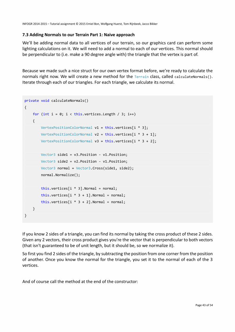
INFOGR 2014-2015 – Tutorial assignment © 2015 Emiel Bon, Wolfgang Huerst, Tom Rijnbeek, Jacco Bikker
Page 43 of 54
7.3 Adding Normals to our Terrain Part 1: Naive approach
We’ll be adding normal data to all vertices of our terrain, so our graphics card can perform some lighting calculations on it. We will need to add a normal to each of our vertices. This normal should be perpendicular to (i.e. make a 90 degree angle with) the triangle that the vertex is part of.
Because we made such a nice struct for our own vertex format before, we’re ready to calculate the normals right now. We will create a new method for the Terrain class, called calculateNormals(). Iterate through each of our triangles. For each triangle, we calculate its normal.
private void calculateNormals()
{
for (int i = 0; i < this.vertices.Length / 3; i++)
{
VertexPositionColorNormal v1 = this.vertices[i * 3];
VertexPositionColorNormal v2 = this.vertices[i * 3 + 1];
VertexPositionColorNormal v3 = this.vertices[i * 3 + 2];
Vector3 side1 = v3.Position - v1.Position;
Vector3 side2 = v2.Position - v1.Position;
Vector3 normal = Vector3.Cross(side1, side2);
normal.Normalize();
this.vertices[i * 3].Normal = normal;
this.vertices[i * 3 + 1].Normal = normal;
this.vertices[i * 3 + 2].Normal = normal;
}
}
If you know 2 sides of a triangle, you can find its normal by taking the cross product of these 2 sides. Given any 2 vectors, their cross product gives you’re the vector that is perpendicular to both vectors (that isn't guaranteed to be of unit length, but it should be, so we normalize it).
So first you find 2 sides of the triangle, by subtracting the position from one corner from the position of another. Once you know the normal for the triangle, you set it to the normal of each of the 3 vertices.
And of course call the method at the end of the constructor:

INFOGR 2014-2015 – Tutorial assignment © 2015 Emiel Bon, Wolfgang Huerst, Tom Rijnbeek, Jacco Bikker
Page 44 of 54
this.calculateNormals();
Please note that when we assign values from the vertices array to the v1, v2 and v3 variables, the complete object gets copied into that variable. Thus, if we make a change to the vertex stored in that variable (e.g. set its normal), nothing changes in the same vertex which is stored in the array of vertices. That is why we don't use the shortcuts when setting the normal in the last tree lines. If the VertexPositionColorNormal was a class, we could have used the shortcut for the last three lines, because the variables v1, v2 and v3 would contain pointers to the objects.
Now run this code and you'll see what I mean with edged lighting: you can clearly see the difference between the triangles! This is what was shown in the left part of the example image above.

INFOGR 2014-2015 – Tutorial assignment © 2015 Emiel Bon, Wolfgang Huerst, Tom Rijnbeek, Jacco Bikker
Page 45 of 54
Chapter 8: Optimizations using indices
8.1 Recycling vertices using indices
Now that you have this much larger number of triangles to render, you have undoubtedly noticed the decrease in FPS with respect to the small amount we rendered in the first few chapters. Depending on what kind of computer you work, the decrease can vary, but it is obvious the process can be optimized. Consider next example:
Only 4 out of 6 vertices are unique. So the other 2 are simply a waste of bandwidth to your graphics card! It would be better to define the 4 vertices in an array from 0 to 3, and to define triangle 1 as vertices 1,2 and 3 and triangle 2 as vertices 2,3 and 4. This way, the complex vertex data is not duplicated. This is exactly the idea behind indices. Suppose we would like to draw these 2 triangles :
Normally we would have to define 6 vertices, with indices, we would define only 5.
As discussed above, the indices refer to individual vertices in our array of vertices. The indices define the triangles, so for 2 triangles we will need to define 6 indices. Indices are integer numbers, and for the HiDef profile, you would define the indices as an array of 32-bit integers. However, the Reach profile ensures compatibility with DirectX 9 hardware, and due to hardware limitations they use so called shorts as indices. A short is almost the same as an int, but where ints are 32-bit numbers, shorts are only 16-bit. So, as long as you keep your number of indices below 216, there is no reason

INFOGR 2014-2015 – Tutorial assignment © 2015 Emiel Bon, Wolfgang Huerst, Tom Rijnbeek, Jacco Bikker
Page 46 of 54
not to use shorts and you will be able to run your project on new as well as older hardware. We will now use indices to improve the efficiency of our terrain. Add the following line to the top of your Terrain class:
private short[] indices;
What we want now is an improved version of our setupVertices() method, so that it doesn't generate a huge number of vertices from the loaded vertices. What we will do is let loadVertices() load the vertices from the height map only once, and we let the array of short indices, which are much smaller than vertices, reference the vertices that have been loaded, instead of copying them over. Rename the method setupVertices() to setupIndices(), remove the parameter and make the following adjustments:
private void setupIndices()
{
this.indices = new short[(this.width - 1) * (this.height - 1) * 6];
int counter = 0;
for (int x = 0; x < this.width - 1; x++)
for (int y = 0; y < this.height - 1; y++)
{
int lowerLeft = x + y * this.width;
int lowerRight = (x + 1) + y * this.width;
int topLeft = x + (y + 1) * this.width;
int topRight = (x + 1) + (y + 1) * this.width;
this.indices[counter++] = (short) topLeft;
this.indices[counter++] = (short) lowerRight;
this.indices[counter++] = (short) lowerLeft;
this.indices[counter++] = (short) topLeft;
this.indices[counter++] = (short) topRight;
this.indices[counter++] = (short) lowerRight;
}
}

INFOGR 2014-2015 – Tutorial assignment © 2015 Emiel Bon, Wolfgang Huerst, Tom Rijnbeek, Jacco Bikker
Page 47 of 54
As you can see, it looks very similar to what we did before with just the vertices. Only now, it only stores the index in the array of vertices, instead of copying the whole vertex over.
Now that the vertices array in the Terrain class is no longer supposed to be filled with a huge number of vertices, we should store the vertices we obtained from the height map there. Remove the old lines in the constructor related to the vertices and replace them by:
this.vertices = this.loadVertices(heightMap, heightScale);
this.setupIndices();
All that's left for this chapter is to draw the triangles using the index data in conjunction with the vertex data. Change the following line in the Draw() method of your Terrain class:
device.DrawUserIndexedPrimitives(PrimitiveType.TriangleList, this.vertices, 0,
this.vertices.Length, this.indices, 0, this.indices.Length / 3);
Instead of using the DrawUserPrimitives() method, this time we call the DrawUserIndexedPrimitives() method. This allows us to specify both an array of vertices and an array of indices. The last argument specifies how many triangles are defined by the indices. Since one triangle is defined by 3 indices, we specify the number of indices divided by 3. Notice also that we left the VertexDeclaration argument out.
If we run the code now however, our lighting is completely wrong, because it depends on the old way of storing vertices to do its lighting calculations. So hurry on to the next chapter, where we will introduce the new way of lighting that looks much more realistic!
8.2 Adding Normals to our Terrain Part 2: Better approach
In cases where the vertex is shared among multiple triangles (as in our terrain), you should find the normal of all triangles that use the vertex, and store the average of those normals in the vertex. In this case we can make good use of the indices. Change the CalculateNormals() method so it looks like this:
private void calculateNormals()
{
for (int i = 0; i < this.indices.Length / 3; i++)
{
short i1 = this.indices[i * 3];
short i2 = this.indices[i * 3 + 1];

INFOGR 2014-2015 – Tutorial assignment © 2015 Emiel Bon, Wolfgang Huerst, Tom Rijnbeek, Jacco Bikker
Page 48 of 54
short i3 = this.indices[i * 3 + 2];
Vector3 side1 = this.vertices[i3].Position - this.vertices[i1].Position;
Vector3 side2 = this.vertices[i2].Position - this.vertices[i1].Position;
Vector3 normal = Vector3.Cross(side1, side2);
normal.Normalize();
this.vertices[i1].Normal += normal;
this.vertices[i2].Normal += normal;
this.vertices[i3].Normal += normal;
}
for (int i = 0; i < this.vertices.Length; i++)
this.vertices[i].Normal.Normalize();
}
You look up the indices for the 3 vertices of the triangle. You calculate the normal as you did before, only now you add it to the normal of the vertex. After the first loop, all vertices contain huge normal vectors, while they need to be of unit length. So end by normalizing all of them, which is the same as averaging them, because each normal you added, had unit length to begin with. That’s it for the normal. When you run this code, you should see the image below (notice the much higher frame rate with respect to your implementation without indices):

INFOGR 2014-2015 – Tutorial assignment © 2015 Emiel Bon, Wolfgang Huerst, Tom Rijnbeek, Jacco Bikker
Page 49 of 54
8.3 Improving performance by using VertexBuffers and IndexBuffers
Each frame, all vertices and indices are being sent over to our graphics card. This means each frame we are sending over exactly the same data. Obviously, this could be optimized. We want to send the data over to the graphics card only once, after which the graphics card should store it in its own super-fast memory. This can be done by storing our vertices in a VertexBuffer, and our indices in an IndexBuffer. Start by declaring these 2 variables at the top of your Terrain class:
private VertexBuffer vertexBuffer;
private IndexBuffer indexBuffer;
We will initialize and fill the VertexBuffer and IndexBuffer in a new method: copyToBuffers(). This code does the trick for the VertexBuffer:
private void copyToBuffers(GraphicsDevice device)
{
this.vertexBuffer = new VertexBuffer(device, VertexPositionColorNormal.VertexDeclaration,
this.vertices.Length, BufferUsage.WriteOnly);
this.vertexBuffer.SetData(this.vertices);
}
The first line creates the VertexBuffer, which comes down to allocating a piece of memory on the graphics card that is large enough to store all our vertices. Therefore, you need to specify how many bytes we need. This is done by specifying the number of vertices in our array, as well as the VertexDeclaration (which contains the size in bytes for one vertex).
The second line actually copies the data from our local vertices array into the memory on our graphics card. We need to do the same for our indices, so put this code at the end of the method:
this.indexBuffer = new IndexBuffer(device, typeof(short), this.indices.Length,
BufferUsage.WriteOnly);
this.indexBuffer.SetData(this.indices);
To find out how many bytes to allocate, we pass in the type of each index as well as how many of them we want to store. The second line copies the indices over to the graphics card. Next we need to let your graphics card know it should read from the buffers stored in its own memory:

INFOGR 2014-2015 – Tutorial assignment © 2015 Emiel Bon, Wolfgang Huerst, Tom Rijnbeek, Jacco Bikker
Page 50 of 54
device.Indices = this.indexBuffer;
device.SetVertexBuffer(this.vertexBuffer);
We want to call this method at the end of our constructor method:
this.copyToBuffers(device);
But for that we need the GraphicsDevice the data is going to be copied to. Let's add that as a parameter to the constructor and don’t forget to pass it from the Game1 as well.
public Terrain(HeightMap heightMap, float heightScale, GraphicsDevice device)
With that done, you only need to instruct your graphics card to fetch the vertex and index data from its own memory using the DrawIndexedPrimitives() method instead of the DrawUserIndexedPrimitives() method. Change it in the Draw() method of the Terrain class:
device.DrawIndexedPrimitives(PrimitiveType.TriangleList, 0, 0, this.vertices.Length, 0,
this.indices.Length / 3);
We indicate where the graphics card should get its indices and vertices from and render the triangles. Running this code will give you the same result as in last chapter. This time however, all vertex and index data is transferred only once to your graphics card! Notice the big increase in FPS!

INFOGR 2014-2015 – Tutorial assignment © 2015 Emiel Bon, Wolfgang Huerst, Tom Rijnbeek, Jacco Bikker
Page 51 of 54

INFOGR 2014-2015 – Tutorial assignment © 2015 Emiel Bon, Wolfgang Huerst, Tom Rijnbeek, Jacco Bikker
Page 52 of 54
Bonus assignments
If you have done everything correct so far (including proper commenting and the readme as specified!) you should be able to get an 8. If you want some extra credit to get the perfect grade 10, you can do the following bonus assignments:
Terrain coloring bonus
Add some nice color to the terrain, based on values that you have present, like the height for instance. Your solution is graded on documentation, aesthetic look and complexity.
For some inspiration, have a look here:
https://www.shadertoy.com/view/4slGD4
This demo calculates terrain color procedurally, based on slope and height.
Elaborate camera bonus
Create a more elaborate camera system that lets you move and rotate the camera through the 3D world. For example, how about a nice implementation that uses the mouse to look around (First Person Shooter camera)? Your solution is graded on documentation, functionality, ease of use and robustness (e.g. does your system deal with the error that occurs when the gaze vector aligns with the up vector?).
An alternative interesting camera could be one that follows a spline path (Catmull-Rom splines are great for this, and relatively easy to implement).
Free style bonus
Feel free to come up with creative ideas to further improve the application using any means you see fit. Perhaps something that involves interaction with the landscape, or additional meshes to improve the visuals, or a skydome.

INFOGR 2014-2015 – Tutorial assignment © 2015 Emiel Bon, Wolfgang Huerst, Tom Rijnbeek, Jacco Bikker
Page 53 of 54
Appendix
1. Visual Studio 2010
A. Cleaning your solution
For submitting your assignment implementation, you have to remove all the compiled files from your solution directory. When you press the Start Debugging button in Visual Studio, your source code gets compiled into an executable file, some files get copied over to the executable's directory and some other files are created. These are the files that you have to remove. You can either manually remove the bin and obj folders from your main and content projects in your solution directory on your hard drive, or you can let Visual Studio do it for you automatically. You can do this by opening the Build menu at the top of the Visual Studio window and select Clean Solution. After this your implementation is ready to be submitted.
Note: If you are using the Visual C# Express edition for your project, the Clean solution option may not be available. In that case you have to use the manual method described above to clean your solution. Remember to remove the folders from both your main project and your content project.
2. C#
A. Structs
If you have a Java background, you might not know what structs are and if you have a C or C++ background, you may have the wrong idea of a struct in C#. In C#, structs are exactly like classes, they have state and behavior (i.e. methods). The only difference is, when creating an instance of a class using the new keyword, the actual object is created on the so called heap, and what you get is a pointer to that object. We say that the object is passed by reference, i.e. only a pointer to the object is passed to the programmer, not the object itself. Structs are created on the stack and are passed by value, so when creating a struct with the new keyword, what you get is the actual object, much like an int or a floating point number. Pay very close attention to whether you are working with either classes or structs, there are subtle differences that can result in programming errors that are very hard to detect!
Example:
Number x = new Number(5);
Number y = x;
y.Value = 3;
If Number is a class, at the end of this code, x.Value equals 3. If Number is a struct, at the end of this code x.Value equals 5. Why? Let's go through it line by line:
1. After the first line, if Number is a class, x contains a pointer to a Number object with value 5. When Number is a struct, x contains the actual Number object with value 5.
2. In the second line, if Number is a class, the variable y gets the same value as the variable x. Because x is a pointer to an object, after this line y also contains a pointer to that same object, i.e. both x and y reference the same object on the heap. The memory usage of this

INFOGR 2014-2015 – Tutorial assignment © 2015 Emiel Bon, Wolfgang Huerst, Tom Rijnbeek, Jacco Bikker
Page 54 of 54
construction is one time the size of the object (on the heap), and two times the size of a pointer to that object (the values of x and y). If Number is a struct, the whole Number object in x gets copied over to y (i.e. gets passed by value), so y now contains a copy of x! This works exactly the same as with ints. In this case, the memory usage is thus two times the size of the object (the values of x and y).
3. Finally, if Number is a class, the last line changes the value of the Number object that y (and also x) point to. If Number is a struct, it only changes the value of the object in y, and does nothing with the object in x.
B. Properties:
Properties are something relatively new in modern programming languages. A property looks exactly like a variable, but is in fact a parameter-less function in disguise. It consists of either a get function or a set function, or both. When requesting the value of the property, the get function is executed, and when changing the value of the property, the set function is executed.
Example:
class Vector2D
{
public float X, Y;
public float Length
{
get { return Math.Sqrt(X * X + Y * Y); }
}
}
You can now access a Vector2D object's length by writing vector.Length, just as you would if Length were a normal variable. The returned value is calculated as a result of the values of X and Y, instead of having to be manually changed when X and Y change. As you can see this allows for less programming errors, because transitive (i.e. indirect) properties of an object can be calculated without explicit use of a function. Because no set function was specified here, you cannot change the value of the Length property (which also makes a lot of sense in this case, another benefit over using a regular variable).
Note: C, C++ and Java do not support properties, C# does.
3. Version Management
You are highly encouraged to use a version management system. A version management system helps manage cases were several people have to work in the same files, as is often the case with programming assignments. It also helps to synchronize and merge the changes that were made.
A very commonly used version management system is Subversion or SVN. A very intuitive Subversion implementation for Windows is Tortoise-SVN, which integrates with Windows Explorer. You can download Tortoise-SVN at http://tortoisesvn.net/downloads.html. A comprehensive (but very extensive) tutorial can be found at http://tortoisesvn.net/support.html.