Influence of EBG Structures on the Far-Field Pattern of ... · Influence of EBG Structures on the...
7
RADIOENGINEERING, VOL. 18, NO. 2, JUNE 2009 223 Influence of EBG Structures on the Far-Field Pattern of Patch Antennas Jiří HORÁK, Zbyněk RAIDA Dept. of Radio Electronics, Brno University of Technology, Purkyňova 118, 612 00 Brno, Czech Republic [email protected], [email protected] Abstract. In this paper, the influence of the EBG structu- res on the far-field pattern of patch antennas is investiga- ted. As a reference model, a conventional rectangular patch antenna on a high-permittivity substrate is used. The reference model is consequently equipped by an EBG substrate (instead of the conventional one), and by an EBG cover (so called EBG superstrate). The changes in the far- field radiation patterns are discussed. In the second part of the paper, the substrate is perturbed by two different EBG structures designed for the coverage of two operation bands. Keywords Patch antenna, EBG substrate, far-field radiation pat- tern, double-band antenna, superstrate. 1. Introduction In recent years, different types of antennas have been used in wireless services. Very popular planar antennas (e.g. patch ones) excel in a low cost, a low profile and a simple mass production. On the other hand, patch anten- nas exhibit a narrow bandwidth and low gain. Moreover, surface waves can be excited in the substrate, which de- creases the antenna efficiency [1]. Propagation of the surface waves can be suppressed by using periodic structures called Electromagnetic Band Gap (EBG) ones. EBG structures can be implemented as metallic-dielectric ones (elements of the periodic layout are etched to the electroplated substrate) and purely dielectric ones (typically, holes are drilled into the dielectric me- dium). Exploitation of both the types of periodic structures was described in several papers. The metallic-dielectric structures were applied to single-band patch antennas and double-band ones positively influencing their radiation patterns and gain [2] – [5]. The purely dielectric EBG structures were applied both in the substrate [6], [7] and in the superstrate of the patch antenna focusing the main beam and increased gain [8]. Nevertheless, all the publis- hed papers presented purely dielectric EBG structures for the single-band exploitation only; or for the operation in two closely neighboring bands. In the open literature, we have not found any paper describing a fully-dielectric EBG structure designed for the coverage of two distant operation bands. The double-band EBG structure proposed in this submission is therefore considered to be the original contribution of the paper. 2. Design of the EBG Structures In the paper, a purely dielectric EBG structure is used to suppress surface waves. The EBG structure is formed by holes drilled into the dielectric material Arlon AR1000 with the dielectric constant 9.8, dissipation factor 0.003, and thickness 3.125 mm. Arlon AR1000 is chosen due to the higher excitation of surface waves. The dimensions of the EBG structure are obtained from an atlas of gap maps [9] through the approximate values of ratios r/a, and f a/c. Here, r is the radius of holes, a is the lattice constant, f denotes frequency and c is the velocity of light. The dimensions r and a are designed so that the band gap for covering the operation band of the antenna can appear between the higher excited modes in the substrate. The investigations are focused on the band gaps between transversally magnetic modes (TM) only since the central frequency of the higher operation band (7.0 GHz) is lower than the cut off frequency of the TE 1 mode (8.0 GHz). The cut off frequency can be calculated using [10]: 1 4 0 0 c − = r r h n f μ ε μ ε , (1) where h is the thickness of the substrate, ε 0 and μ 0 are per- mitivity and permeability of the vacuum, ε r and μ r are relative permitivity and permeability of the dielectric ma- terial, n = 0, 2, 4, … for TM modes and n = 1, 3, 5, … for TE modes. The main parameters of the EBG structure can be accurately computed by the program MIT Photonic Band Package [11]. We obtained a = 42.1 mm and r = 20.95 mm for the lower operation band with the central frequency 5.175 GHz (the bandwidth is 1.1%), and a = 31.2 mm and
Transcript of Influence of EBG Structures on the Far-Field Pattern of ... · Influence of EBG Structures on the...

RADIOENGINEERING, VOL. 18, NO. 2, JUNE 2009 223
Influence of EBG Structures on the Far-Field Pattern of Patch Antennas
Jiří HORÁK, Zbyněk RAIDA
Dept. of Radio Electronics, Brno University of Technology, Purkyňova 118, 612 00 Brno, Czech Republic
[email protected], [email protected]
Abstract. In this paper, the influence of the EBG structu-res on the far-field pattern of patch antennas is investiga-ted. As a reference model, a conventional rectangular patch antenna on a high-permittivity substrate is used. The reference model is consequently equipped by an EBG substrate (instead of the conventional one), and by an EBG cover (so called EBG superstrate). The changes in the far-field radiation patterns are discussed.
In the second part of the paper, the substrate is perturbed by two different EBG structures designed for the coverage of two operation bands.
Keywords Patch antenna, EBG substrate, far-field radiation pat-tern, double-band antenna, superstrate.
1. Introduction In recent years, different types of antennas have been
used in wireless services. Very popular planar antennas (e.g. patch ones) excel in a low cost, a low profile and a simple mass production. On the other hand, patch anten-nas exhibit a narrow bandwidth and low gain. Moreover, surface waves can be excited in the substrate, which de-creases the antenna efficiency [1].
Propagation of the surface waves can be suppressed by using periodic structures called Electromagnetic Band Gap (EBG) ones. EBG structures can be implemented as metallic-dielectric ones (elements of the periodic layout are etched to the electroplated substrate) and purely dielectric ones (typically, holes are drilled into the dielectric me-dium).
Exploitation of both the types of periodic structures was described in several papers. The metallic-dielectric structures were applied to single-band patch antennas and double-band ones positively influencing their radiation patterns and gain [2] – [5]. The purely dielectric EBG structures were applied both in the substrate [6], [7] and in the superstrate of the patch antenna focusing the main beam and increased gain [8]. Nevertheless, all the publis-hed papers presented purely dielectric EBG structures for
the single-band exploitation only; or for the operation in two closely neighboring bands.
In the open literature, we have not found any paper describing a fully-dielectric EBG structure designed for the coverage of two distant operation bands. The double-band EBG structure proposed in this submission is therefore considered to be the original contribution of the paper.
2. Design of the EBG Structures In the paper, a purely dielectric EBG structure is used
to suppress surface waves. The EBG structure is formed by holes drilled into the dielectric material Arlon AR1000 with the dielectric constant 9.8, dissipation factor 0.003, and thickness 3.125 mm. Arlon AR1000 is chosen due to the higher excitation of surface waves.
The dimensions of the EBG structure are obtained from an atlas of gap maps [9] through the approximate values of ratios r/a, and f a/c. Here, r is the radius of holes, a is the lattice constant, f denotes frequency and c is the velocity of light. The dimensions r and a are designed so that the band gap for covering the operation band of the antenna can appear between the higher excited modes in the substrate. The investigations are focused on the band gaps between transversally magnetic modes (TM) only since the central frequency of the higher operation band (7.0 GHz) is lower than the cut off frequency of the TE1 mode (8.0 GHz).
The cut off frequency can be calculated using [10]:
14 00
c −=
rrhnf
μεμε , (1)
where h is the thickness of the substrate, ε0 and μ0 are per-mitivity and permeability of the vacuum, εr and μr are relative permitivity and permeability of the dielectric ma-terial, n = 0, 2, 4, … for TM modes and n = 1, 3, 5, … for TE modes.
The main parameters of the EBG structure can be accurately computed by the program MIT Photonic Band Package [11]. We obtained a = 42.1 mm and r = 20.95 mm for the lower operation band with the central frequency 5.175 GHz (the bandwidth is 1.1%), and a = 31.2 mm and

224 J. HORÁK, Z. RAIDA, INFLUENCE OF THE EBG STRUCTURES ON THE FAR-FIELD PATTERN OF THE PATCH ANTENNAS
r = 15.5 mm for the higher operation band with the central frequency 7.000 GHz (the bandwidth is again 1.1%).
3. Design and Simulations of Patch Antennas
3.1 Antenna on Conventional Substrate First, a simple patch antenna on a conventional sub-
strate is modeled and simulated to obtain far-field patterns. The rectangular patch is designed to operate at the frequen-cy 7.000 GHz. The dimensions of the antenna are depicted in Fig. 1. The antenna is fed by a coaxial probe situated in the distance 1.55 mm from the center of the patch. The total size of the antenna is set with regard to the computed parameters of the EBG structure.
Fig. 1. Dimensions of the antenna in millimeters.
The antenna was modeled and simulated in CST Microwa-ve Studio (MWS). The computed impedance matching and directivity patterns of the antenna for frequency 7.000 GHz are depicted in Fig. 2 and Fig. 3. Obviously, the patch an-tenna is matched well at the desired frequency, and does not radiate perpendicularly to the plane of the substrate. In order to verify obtained results, the antenna was computed in Ansoft HFSS also (frequency domain finite elements versus time domain finite differences).
-25
-20
-15
-10
-5
06,5 6,6 6,7 6,8 6,9 7 7,1 7,2 7,3 7,4 7,5
f [GHz]
S11
[dB
]
MWS HFSS
Fig. 2. Frequency response of the reflection coefficient of the patch antenna on the conventional substrate.
-30
-25
-20
-15
-10
-5
0
5-180 -150 -120 -90 -60 -30 0 30 60 90 120 150 180
Theta [°]
G [d
B]
MWS HFSS
-30
-25
-20
-15
-10
-5
0-180 -150 -120 -90 -60 -30 0 30 60 90 120 150 180
Theta [°]
G [d
B]
MWS HFSS Fig. 3. Directivity patterns of the patch antenna on the
conventional substrate in E plane (top) and H plane (bottom). The angle Theta = 0 is perpendicular to the plane of the antenna.
Fig. 4. Distribution of the Ez component (perpendicular) of
the antenna on the conventional substrate.
3.2 Antenna on EBG Substrate In order to enhance the antenna radiation in the per-
pendicular direction, the EBG structure replaces the conventional substrate (three rows of holes are drilled around the patch). The length of the patch is changed to 12.6 mm. Fig. 5 and Fig. 6 show that the antenna is well matched again but the radiation pattern does not change

RADIOENGINEERING, VOL. 18, NO. 2, JUNE 2009 225
significantly. Only some side lobes are unified and the gain is increased slightly in the main lobe direction.
-30
-25
-20
-15
-10
-5
06,5 6,6 6,7 6,8 6,9 7 7,1 7,2 7,3 7,4 7,5
f [GHz]
S11
[dB
]
MWS HFSS Fig. 5. Frequency response of the reflection coefficient of the
patch antenna on the EBG substrate.
-30
-25
-20
-15
-10
-5
0
5
10-180 -150 -120 -90 -60 -30 0 30 60 90 120 150 180
Theta [°]
G [d
B]
MWS HFSS
-30
-25
-20
-15
-10
-5
0
5-180 -150 -120 -90 -60 -30 0 30 60 90 120 150 180
Theta [°]
G [d
B]
MWS HFSS Fig. 6. Directivity patterns of the patch antenna on the EBG
substrate in E plane (top) and H plane (bottom). The angle Theta = 0 is perpendicular to the plane of the antenna.
The EBG substrate did not significantly influence the directivity pattern since the main direction of the patch radiation was not directly oriented to the plane of the substrate but was deflected by 10° over the plane of the substrate approximately.
3.3 Antenna on EBG Substrate Covered by EBG Superstrate In order to improve the perpendicular radiation, an
EBG superstrate of the same parameters like the substrate is added to the antenna with zero distance from the top of the substrate. Hence, the patch is drowned now in the dielectric material of total thickness 6.25 mm.
Fig. 7. Distribution of the Ez component (perpendicular) of
the antenna on the EBG substrate.
In order to keep the antenna well matched, the length and the width of the patch are changed to 13.32 mm and 8.00 mm. The coaxial excitation is moved to 2.00 mm.
-20
-18
-16
-14
-12
-10
-8
-6
-4
-2
06,5 6,6 6,7 6,8 6,9 7 7,1 7,2 7,3 7,4 7,5
f [GHz]
S11
[dB
]
MWS HFSS Fig. 8. Frequency response of the reflection coefficient of the
patch antenna on EBG substrate with EBG superstrate. The model of the antenna on the EBG substrate is depicted in the corner.
Obviously, the nearly perpendicular radiation is achieved (Fig. 9), and the gain is increased by 4 dB approximately.
226 J. HORÁK, Z. RAIDA, INFLUENCE OF THE EBG STRUCTURES ON THE FAR-FIELD PATTERN OF THE PATCH ANTENNAS
-40
-30
-20
-10
0
10
20-180 -150 -120 -90 -60 -30 0 30 60 90 120 150 180
Theta [°]
G [d
B]
MWS HFSS
-40
-30
-20
-10
0
10
20-180 -150 -120 -90 -60 -30 0 30 60 90 120 150 180
Theta [°]
G [d
B]
MWS HFSS Fig. 9. Directivity patterns of the patch antenna on the EBG
substrate with EBG superstrate in E plane (top) and H plane (bottom). The angle Theta = 0 is perpendicular to the plane of the antenna.
Fig. 10. Three-dimensional directivity pattern of the patch anten-
na on the EBG substrate with the EBG superstrate.
Fig. 10 shows that most energy is radiated in the nearly perpendicular direction.
3.4 Antenna for Lower Band In final, two different EBG structures for two diffe-
rent frequency bands are placed around the patch to sup-
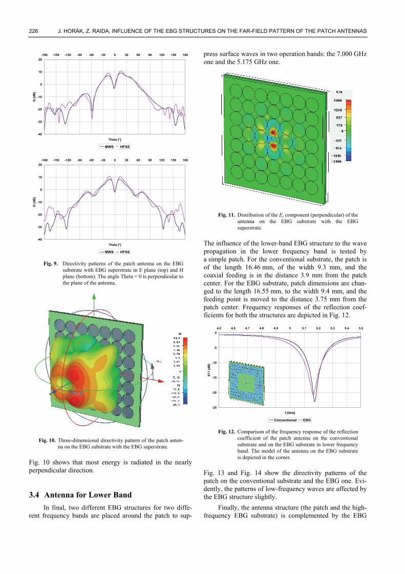
press surface waves in two operation bands: the 7.000 GHz one and the 5.175 GHz one.
Fig. 11. Distribution of the Ez component (perpendicular) of the
antenna on the EBG substrate with the EBG superstrate.
The influence of the lower-band EBG structure to the wave propagation in the lower frequency band is tested by a simple patch. For the conventional substrate, the patch is of the length 16.46 mm, of the width 9.3 mm, and the coaxial feeding is in the distance 3.9 mm from the patch center. For the EBG substrate, patch dimensions are chan-ged to the length 16.55 mm, to the width 9.4 mm, and the feeding point is moved to the distance 3.75 mm from the patch center. Frequency responses of the reflection coef-ficients for both the structures are depicted in Fig. 12.
-25
-20
-15
-10
-5
04,5 4,6 4,7 4,8 4,9 5 5,1 5,2 5,3 5,4 5,5
f [GHz]
S11
[dB
]
Conventional EBG Fig. 12. Comparison of the frequency response of the reflection
coefficient of the patch antenna on the conventional substrate and on the EBG substrate in lower frequency band. The model of the antenna on the EBG substrate is depicted in the corner.
Fig. 13 and Fig. 14 show the directivity patterns of the patch on the conventional substrate and the EBG one. Evi-dently, the patterns of low-frequency waves are affected by the EBG structure slightly.
Finally, the antenna structure (the patch and the high-frequency EBG substrate) is complemented by the EBG

RADIOENGINEERING, VOL. 18, NO. 2, JUNE 2009 227
structure for the low-frequency band (holes of a larger ra-dius around the high-frequency EBG). Moreover, the an-tenna is covered by the EBG superstrate, which is identical with the substrate. The thickness of the final structure is 6.25 mm. The size of the whole antenna is 540 mm × 540 mm. The final model of the antenna is depicted in Fig. 15.
-35
-30
-25
-20
-15
-10
-5
0
5
10-180 -150 -120 -90 -60 -30 0 30 60 90 120 150 180
Theta [°]
G [d
B]
Conventional EBG Fig. 13. Comparison of the directivity patterns of the patch
antenna on the conventional substrate and on the EBG substrate in lower frequency band for E plane.
-35
-30
-25
-20
-15
-10
-5
0-180 -150 -120 -90 -60 -30 0 30 60 90 120 150 180
Theta [°]
G [d
B]
Conventional EBG Fig. 14. Comparison of the directivity patterns of the patch an-
tenna on the conventional substrate and on the EBG substrate in lower frequency band for H plane.
Fig. 15. Top view on the model of the antenna with the dual-
band EBG superstrate and the identical EBG substrate.
-30
-25
-20
-15
-10
-5
04,5 4,6 4,7 4,8 4,9 5 5,1 5,2 5,3 5,4 5,5
f [GHz]
S11
[dB
]
-20
-18
-16
-14
-12
-10
-8
-6
-4
-2
06,5 6,6 6,7 6,8 6,9 7 7,1 7,2 7,3 7,4 7,5
f [GHz]
S11
[dB
]
Fig. 16. Frequency response of the reflection coefficient of the
patch antenna on the dual-band EBG substrate com-pleted by the dual-band EBG superstrate in the lower frequency band (top) and the higher frequency band (bottom).
-50
-40
-30
-20
-10
0
10-180 -150 -120 -90 -60 -30 0 30 60 90 120 150 180
Theta [°]
G [d
B]
E-plane H-plane
-50
-40
-30
-20
-10
0
10-180 -150 -120 -90 -60 -30 0 30 60 90 120 150 180
Theta [°]
G [d
B]
E plane H plane Fig. 17. Directivity patterns of the patch antenna on the dual-
band EBG substrate completed by the dual-band EBG superstrate in the lower frequency band (top) and the higher frequency band (bottom).

228 J. HORÁK, Z. RAIDA, INFLUENCE OF THE EBG STRUCTURES ON THE FAR-FIELD PATTERN OF THE PATCH ANTENNAS
Numerical simulations of the patch antennas on the dual-band EBG substrate completed by the dual-band superstrate show a good impedance matching at the operation frequencies (Fig. 16): s11 < –25 dB at the lower frequency, and s11 < –18 dB at the higher one.
Directivity patterns of the antennas in both the fre-quency bands are depicted in Fig. 17: the influence of the high-frequency EBG structure to the low-frequency radi-ation is weak, and vice versa.
Three-dimensional radiation patterns of the EBG an-tennas for both the frequency bands are depicted in Fig. 18, and the distribution of the perpendicular Ez component is given in Fig. 19.
Fig. 18. The three-dimensional directivity pattern of the patch
antenna on the dual-band EBG substrate completed by the dual-band EBG superstrate in the lower frequency band (top) and the higher frequency band (bottom).
Both Fig. 18 and Fig. 19 show that the antenna radiation in the lower frequency band is not influenced by the high-frequency EBG structure, and vice versa.
4. Conclusion In the paper, the EBG concept was applied to the
design of two simple patch antennas with different fre-quency bands in order to suppress the surface wave pro-pagation in the dielectric substrate (an EBG substrate) and improve the radiation in the perpendicular direction (an EBG superstrate). Both the substrate and the superstrate were of the same geometry.
The EBG structures were conceived as an inner EBG region and an outer one. The inner EBG region suppressed the propagation of high-frequency waves, and did not in-fluenced low-frequency waves. The outer EBG region sup-pressed the low-frequency waves, which passed through the inner EBG region.
Fig. 19. Distribution of the Ez component (perpendicular) of the patch antenna on the dual-band EBG substrate completed by the dual-band EBG superstrate in the lower frequency band (top) and the higher frequency band (bottom).

RADIOENGINEERING, VOL. 18, NO. 2, JUNE 2009 229
Properties of the dual-band EBG structure were tested by computer simulations in CST Microwave Studio and Ansoft HFSS. Both the programs provided comparable results proving a good impedance matching, satisfactory surface wave suppression, and an improved radiation in both the investigated frequency bands.
Properties of the designed antenna are going to be verified by an experiment in a near future.
Acknowledgements The research described in this contribution was
financially supported by the Czech Grant Agency under the grant no. 102/07/0688, and by the research program MSM 0021630513: Advanced Communication Systems and Technologies. The research is a part of the COST project IC0603 ASSIST supported by the Czech Ministry of Education under grant no. OC08027.
References [1] ITTIPIBOON, A., GARG, R., BAHL, I., BHARTIA, P. Microstrip
Antenna Design Handbook. Norwood: Artech House, 2000.
[2] CHANG, C. C., QIAN, Y., ITOH, T. Analysis and applications of uniplanar compact photonic bandgap structures. In Progress on Electromagnetics Research Symposium PIERS 41, 2003, p. 211 to 235.
[3] LLOMBART, N., NETO, A., GERINI, G., DE MAAGT, P. Planar circularly symmetric EBG structures for reducing surface waves in printing antennas. IEEE Transactions on Antennas and Propagation, 2005, vol. 53, no. 10, p. 3210–3218.
[4] KERN, D. J., WERNER, D. H., MONORCHIO, A., LANUZZA, L., WILHELM, L. J. The design synthesis of multiband artificial magnetic conductors using high impedance frequency selective surfaces. IEEE Transactions on Antennas and Propagation, 2005, vol. 53, no. 1, p. 8–17.
[5] YANG, L., FAN, M., CHEN, F., SHE, J., FENG, Z. A novel com-pact electromagnetic-bandgap (EBG) structure and its applications for microwave circuits. IEEE Transactions on Microwave Theory and Techniques, 2005, vol. 53, no. 1, p. 183–190.
[6] GONZALO, R., DE MAAGT, P., SOROLLA, M. Enhanced patch-antenna performance by suppressing surface waves using
photonic-bandgap substrates. IEEE Transactions on Microwave Theory and Techniques, 1999, vol. 47, no. 11, p. 2131–2138.
[7] AGI, K., MOJAHEDI, M., MINHAS, B., SCHAMILOGLU, E., MALLOY, K. J. The effects of an electromagnetic crystal substrate on a microstrip patch antenna. IEEE Transactions on Antennas and Propagation, 2002, vol. 50, no. 4, p. 451–456.
[8] LIN, Q., ZHU, F., HE, S. A new photonic bandgap cover for a patch antenna with a photonic bandgap substrates. Journal of Zhejiang University, 2004, no. 5, p. 269–273.
[9] ALLEN, M. Gap maps for photonic crystals [online]. Helsinki University of Technology, 2003. Available at> http://www.hut.fi/~mallen/pbg_band_gaps.ps
[10] WATERHOUSE, R. B. Microstrip Patch Antennas: A Designer’s Guide. Norwell: Kluwer Academic Publishers, 2003.
[11] MIT Photonic Bands [online]. Available at: http://abinitio.mit.edu/wiki/index.php/MIT_Photonic_Bands
About Authors... Jiří HORÁK was born in 1981. He received Ing (M.Sc.) degrees from the Brno University of Technology (BUT) in 2005. Now, he has been working towards the PhD at the Dept. of Radio Electronics, BUT. His research interests are focused on the design of planar antennas with advanced substrates and superstrates.
Zbyněk RAIDA received Ing. (M.Sc.) and Dr. (Ph.D.) degrees from the Brno University of Technology in 1991 and 1994, respectively. Since 1993, he has been with the Dept. of Radio Electronics, FEEC BUT as assistant profes-sor (1993 to 1998), associate professor (1999 to 2003), and professor (since 2004). In 1997, he spent 6 months at the Laboratoire de Hyperfrequences, Universite Catholique de Louvain, Belgium as independent researcher. Prof. Raida has authored or coautored more than 100 papers in scien-tific journals and conference proceedings. His research is focused on numerical modeling and optimization of elec-tromagnetic structures, application of neural networks to modeling and design of microwave structures, and on adaptive antennas. Prof. Raida is a member of the IEEE Microwave Theory and Techniques Society and since 2003 Senior Member of IEEE. He chaired the MTT/AP/ED joint section of the Czech-Slovak chapter of IEEE (2001-2003).