Inertial measurement techniques for human joints' movement ...
9
Inertial measurement techniques for human joints' movement analysis NWAIZU, Harriet, SAATCHI, Reza <http://orcid.org/0000-0002-2266-0187> and BURKE, Derek Available from Sheffield Hallam University Research Archive (SHURA) at: http://shura.shu.ac.uk/16791/ This document is the author deposited version. You are advised to consult the publisher's version if you wish to cite from it. Published version NWAIZU, Harriet, SAATCHI, Reza and BURKE, Derek (2017). Inertial measurement techniques for human joints' movement analysis. In: CUDD, Peter and DEWITTE, Luc, (eds.) Harnessing the power of technology to improve lives. Studies in Health Technology and Informatics (242). IOS Press, 717-724. Copyright and re-use policy See http://shura.shu.ac.uk/information.html Sheffield Hallam University Research Archive http://shura.shu.ac.uk
Transcript of Inertial measurement techniques for human joints' movement ...
Inertial measurement techniques for human joints' movement analysis
NWAIZU, Harriet, SAATCHI, Reza <http://orcid.org/0000-0002-2266-0187> and BURKE, Derek
Available from Sheffield Hallam University Research Archive (SHURA) at:
http://shura.shu.ac.uk/16791/
This document is the author deposited version. You are advised to consult the publisher's version if you wish to cite from it.
Published version
NWAIZU, Harriet, SAATCHI, Reza and BURKE, Derek (2017). Inertial measurement techniques for human joints' movement analysis. In: CUDD, Peter and DEWITTE, Luc, (eds.) Harnessing the power of technology to improve lives. Studies in Health Technology and Informatics (242). IOS Press, 717-724.
Copyright and re-use policy
See http://shura.shu.ac.uk/information.html
Sheffield Hallam University Research Archivehttp://shura.shu.ac.uk

Inertia Measurement Techniques for
Human Joints' Movement Analysis
Harriet NWAIZU a , Reza SAATCHI
a,1 and Derek BURKE
b
a Materials and Engineering Research Institute, Sheffield Hallam University, Sheffield,
UK. b
Sheffield Children's Hospital, Sheffield, UK.
Abstract. Development and assessment of techniques that allow inertia measurement units
consisting of an accelerometer and a gyroscope to be used for monitoring human joints' movements are presented. A new wavelet packet decomposition technique was developed
that denoised the accelerometer signals. Investigations on the use of accelerometers to
analyse legs’ movements are described.
Keywords. joints’ movement analysis, accelerometry, wavelet analysis, gait analysis
1. Introduction
Assessment of human joints' movements has been of great interest to many researchers
and medical practitioners due to its importance for diagnosing and monitoring several
medical conditions [1][2]. Movement analysis is important in assessing disabilities
such as those affecting balance that increase the likelihood of fall and associated
injuries. Many of these conditions are directly related to mobility-impaired or mobility
reducing disorders such as arthritis, obesity, stroke, chronic pulmonary disease,
multiple sclerosis and Parkinson’s disease [2].
The gold standard for movement analysis utilises a complex camera (vision) based
aparatus. Although the method can be accurate, it has shortcomings that include its
high cost, its restriction to being available primarily at some specialised gait
laboratories and its complex procedures for data recording and analysis [3]. Recent
technological developments in areas of nano and microprocessor technologies,
computing and digital signal processing have resulted in major technological advances
for measuring, monitoring and quantifying human movements [4] using
Microelectromechanical Systems (MEMS) based on powerful integrated circuits called
Inertia Measurement Units (IMUs). A typical IMU consists of a three-axis
accelerometer, a three-axis gyroscope and a three-axis magnetometer and can be used
to measure acceleration, angular rate of rotation and magnetic field vector respectively
in their three-dimensional local coordinate systems [5].
In theory, the movements’ measurements obtained using IMUs once processed
using suitably designed algorithms can estimate important information such as rotation,
acceleration, orientation and distance. There are however some challenges in deploying
IMUs for measuring and analysing patterns of human movements in practical scenarios.
The data obtained from the IMUs are prone to various errors that reduce their accuracy
1 Corresponding Author, Department of Engineering and Mathematics, Sheffield Hallam University,
City Campus, Sheaf Building, Howard Street, Sheffield S1 1WB, UK, E-mail: [email protected].

of analysis. Also, interpreting and relating the outputs from an IMU (accelerometer,
gyroscope and magnetometer) to actual movement patterns require carefully designed
models. In some studies, to improve the IMUs' effectiveness, the movement related
information is estimated by combining (for fusing) the signals from an accelerometer
and a gyroscope using a variety of algorithms such as the Kalman and complementary
filters so that they complement each other’s abilities [6].
Accelerometers have been reported to be very effective in posture and motion
analysis, for detecting cyclical movements and conditions of daily living [7].
Accelerometer data were used to develop an efficient system for assessing static and
dynamic balance and postural sway [8]. Mayagoitia et al. [9] used a tri-axial
accelerometer to measure and monitor human balance. Luinge and Veltink [10]
attached 3D accelerometers to the back of the trunk at the T4/T5 level and the pelvis to
estimate the inclination of the body segments for monitoring daily life tasks, focusing
on lifting and stacking objects. Kavanagh and Menz [11] reviewed the literature that
used this technique for quantifying human movement and concluded that accelerometry
techniques are accurate and reliable for providing information related to walking and
gait patterns.
A gyroscope indicates the rate a body's rotation and so to obtain the actual angle of
rotation, the gyroscope’s signal needs to be integrated. Therefore an initial offset in the
gyroscope's output results in a gradually increasing amplitude drift that obscures the
movement information. An accelerometer on the other hand suffers from noise during a
movement's initiation or when there is a sudden change in the movement's direction.
By combining the outputs from the gyroscope and accelerometer, these two
shortcomings can to an extent be resolved. A number of approaches for combining the
gyroscope and accelerometer signals were reported. Hong [12] developed a fuzzy logic
based complementary filter for determining attitude reference. Shen et al. [13] took this
research further and designed an SPSA (simultaneous stochastic approximation
algorithm) based on fuzzy complementary filter. Calusdian et al. [14] designed an
adaptive-gain quaternion-based complementary filter algorithm that could accurately
track orientation during dynamic and slow motion for tracking foot orientation during
standing and swing phase. Tseng et.al [15] proposed a method to combine passive
complementary filter and observer estimation methods to improve attitude estimation.
Tian et al. [16] proposed an adaptive-gain complementary filter.
However, despite extensive progress in utlising IMUs for movement analysis,
there remain significant challenges in applying them for practical problem solving
situations. For example in real-time clinical assessments and monitoring activities of
daily living, problems such as heavy computational demands need careful
consideration. Hence, there is a need for further research and development to enhance
ways IMUs are employed and their data are processed and interpreted.
In this study, a novel wavelet packet decomposition based technique to denoise
accelerometer signals using the gyroscope as a guide was developed and its
effectiveness was compared with the well-known complementary filter method. The
study also includes an investigation of accelerometer based techniques to measure the
legs’ movement angle, velocity, acceleration and displacement to assist in clinical
diagnosis and rehabilitation purposes.

2. Methods
In this section initially a method devised to denoise accelerometer signals is described
then accelerometer based experiments to analyse legs' movements are explained.
2.1. Wavelet packet based method to denoise accelerometer signals
A technique based on wavelet packet decomposition (a generalisation of wavelet
decomposition) was developed to denoise accelerometer signal using the gyroscope
signal as a guide. This part of the study was based on simulated accelerometer and
gyroscope signals (Figure 1) to facilitate an evaluation of the effectiveness of the
methods. The simulated accelerometer signal shown in Figure 1 (top figure) represents
a leg's movements in a simplified form. Gaussian noise was added to this signal to
represent the effect of measurement noise (shown in Figure 1, middle). The simulated
gyroscope signal (shown in Figure 1, bottom) had an amplitude drift that increases with
time.
Figure 1. Simulated accelerometer signal (top), noisy accelerometer signal (middle) and gyroscope
signal with drift (bottom).
In wavelet packet, a signal is successively decomposed by suitably chosen lowpass
and highpass filters and at each stage of decomposition, the resulting signals are down
sampled by a factor of 2. The outputs of the lowpass filter and highpass filters represent
the coarse and detail information of the signal respectively. The decomposition is
successively repeated in the similar manner for the required number of stages (called
levels). The noisy accelerometer and drifting gyroscope signals were both decomposed
separately using Matlab©
to 8 levels using the Daubechies 20 wavelet family (filter).
The coefficients of the terminal nodes were expressed as nodes 255 to 510. The values
of these nodes for both the decomposed noisy accelerometer and drifting gyroscope
signals were compared for similarity by performing correlation. Two nodes with the
largest correlation magnitude (i.e. closest similarity) were chosen and the values of the
nodes that were not selected were set to zero. The accelerometer signal was then
reconstructed based on the new wavelet packet coefficients for the noisy accelerometer.
The reconstructed accelerometer signal obtained using the above method was
compared with the complementary filter approach for combining the noisy
accelerometer and drifting gyroscope signals. The movement angle from the
complementary filter was obtained from Eq. (1) as
𝜃𝑐𝑢𝑟𝑟𝑒𝑛𝑡 = 𝛼(𝜃𝑝𝑟𝑒𝑣𝑖𝑜𝑢𝑠 + ∆𝑡𝜃𝑔) + (1 − 𝛼)𝜃𝑎 (1)

The complementary filter algorithm was designed using the filter parameter α=
0.98, making the design rely more heavily on the gyroscope's based angle (𝜃𝑔) than the
accelerometer angle (𝜃𝑎). The sampling interval ∆𝑡= 0.018 seconds (corresponding to
sample rate of 55 samples per second).
2.2. Accelerometry techniques for measuring legs' movements
In this part of the study, four tri-axial accelerometer boards (ADXL335 from Sparkfun)
with dimensions 4 mm × 4 mm × 1.45 mm were used for the experiments. The
ADXL335 measures a minimum full-scale range of ±3 g [17] [18]. These boards were
connected to an Arduino Mega 2560 microcontroller board, that in turn was connected
up to a computer via a USB cable. The microcontroller board digitised the analogue x,
y and z accelerometer signals for display, storage and processing by the computer. The
data recording sample rate was 244 samples/second [18], which was sufficient to avoid
aliasing. The accelerometers were attached to the left and right thighs and shanks of a
healthy adult subject as he performed the following movements:
Sleeping on his back on the floor and fully stretched one of his legs to touch the
floor and then bent it fully toward his chest, repeating 30 times. This was repeated
for the other leg.
Walking normally the length of a long (about 20 m) corridor.
The movement angles were calculated from the accelerometer signals using [18]
𝛼𝑡ℎ𝑖𝑔ℎ = 𝑡𝑎𝑛−1 𝑎𝑥1
𝑎𝑧1 (2)
𝛽𝑠ℎ𝑎𝑛𝑘 = 𝑡𝑎𝑛−1 𝑎𝑥2
𝑎𝑧2 (3)
∅𝑗𝑜𝑖𝑛𝑡 = 𝑎𝑡ℎ𝑖𝑔ℎ + 𝛽𝑠ℎ𝑎𝑛𝑘 (4)
Where αthigh, βshank and Øjoint are the tilt angles of the thigh and shank, and the relative
joint angle respectively; αx1 and αz1 are the acceleration measures for the x and z axes of
the accelerometer attached to the thigh and αx2 and αz2 are the acceleration measures for
the x and z axes of the accelerometer attached to the shank. Once the legs' joint angle
was determined, the angular velocity (v), angular acceleration (a) total angular
displacement (d) were obtained from it using [18]
( )
( )d
v tdt
(5)
( )( )
d va t
dt (6)
0
( )t T
td v t
(7)
where T is the signal recording duration.

3. Results and discussion
3.1. Wavelet packet based method to denoise accelerometer signal
The correlation between the terminal nodes of the wavelet packet for the noisy
accelerometer and time drifting gyroscope signals indicated that the nodes with the two
highest similarities were nodes 255 and 258 (Figure 2). These nodes were then selected
with the values of the remaining nodes set to zero to re-construct the accelerometer
signal as shown in Figure 3.
Figure 3 shows the original simulated accelerometer signal, the denoised
accelerometer signal obtained using the wavelet packet decomposition technique and
the signal obtained from the complementary filter. The denoised accelerometer signal
obtained using the wavelet packet method is significantly more similar to the original
signal as compared with the signal obtained using the complementary filter. Wavelet
packet processes a signal at different frequency bands and thus can be more effective in
representing the characteristics of the signal and noise than the complementary filter.
The method is thus valuable in denoising accelerometer signals.
3.2. Accelerometry techniques for measuring legs' movements
The accelerometer derived information data obtained from the legs while the subject
slept on his back and moved his legs in turn from fully stretched on the ground to fully
bent close to the chest are shown in Figures 4 and 5 and the related data are
summarised in Table 1. Table 2 shows the angular velocity, acceleration and total
displacement results for the legs' movements when the subject slept on his back. The
results indicate that the right leg moved faster than the left leg and had a total
displacement of 89.2 radians (over the duration of the recording) as compared with the
left leg that had total a total displacement of 79.2 radians.
Figure 2. Wavelet packet correlation plot.
Figure 3. The original accelerometer signal
(blue), those from the complementary filter (black) and the wavelet packet (red).

In the walking scenario shown (results summarized in Tables 3 and 4 and shown
in Figures 6 and 7), the angular range of movement was wider for the left leg than the
right leg. The angular velocity, acceleration and total displacement values were also
higher for the left than the right leg. The largest peaks present in the magnitude
frequency spectrum of the legs' angular movements were at 0.77 Hz, 1.55 Hz and 2.33
Hz with the dominant frequency appearing at 1.55Hz.
Table 1. Legs' movement range and frequency when subject slept on his back
Leg Movement Range
(degrees)
Movement Frequency
(Hz)
Left 52.9 - 167.9 0.26
Right 43.9 - 163.1 0.26
Table 2. Legs' movement angular velocity, acceleration and total displacement when subject slept on his
back
Leg
Angular Velocity
(rad/s)
Acceleration
(rad/s2)
Total Displacement
(rad)
Left 2.85 27.09 79.15
Right 3.50 38.34 85.19
Table 3. Legs' movement range and frequency when the subject walked
Legs Movement
Range(degree)
Frequency (Hz)
associated with the three
largest peaks in the
magnitude spectrum
Left leg 101.7 - 274.5 0.77, 1.55, 2.33
Right leg 115.2 - 284.1 0.77, 1.55, 2.33
Table 4. Velocity, acceleration and total displacement when the subject walked
Leg Angular Velocity
(rad/s)
Acceleration
(rad/s2)
Total Displacement
(radians)
Left 24.63 436 216.4
Right 23.75 411 196.3
Figure 4. Angle measurement for the left leg
while subject slept on his back.
Figure 5. Angle measurement for the right leg while subject slept on his back.
while subject slept on his back
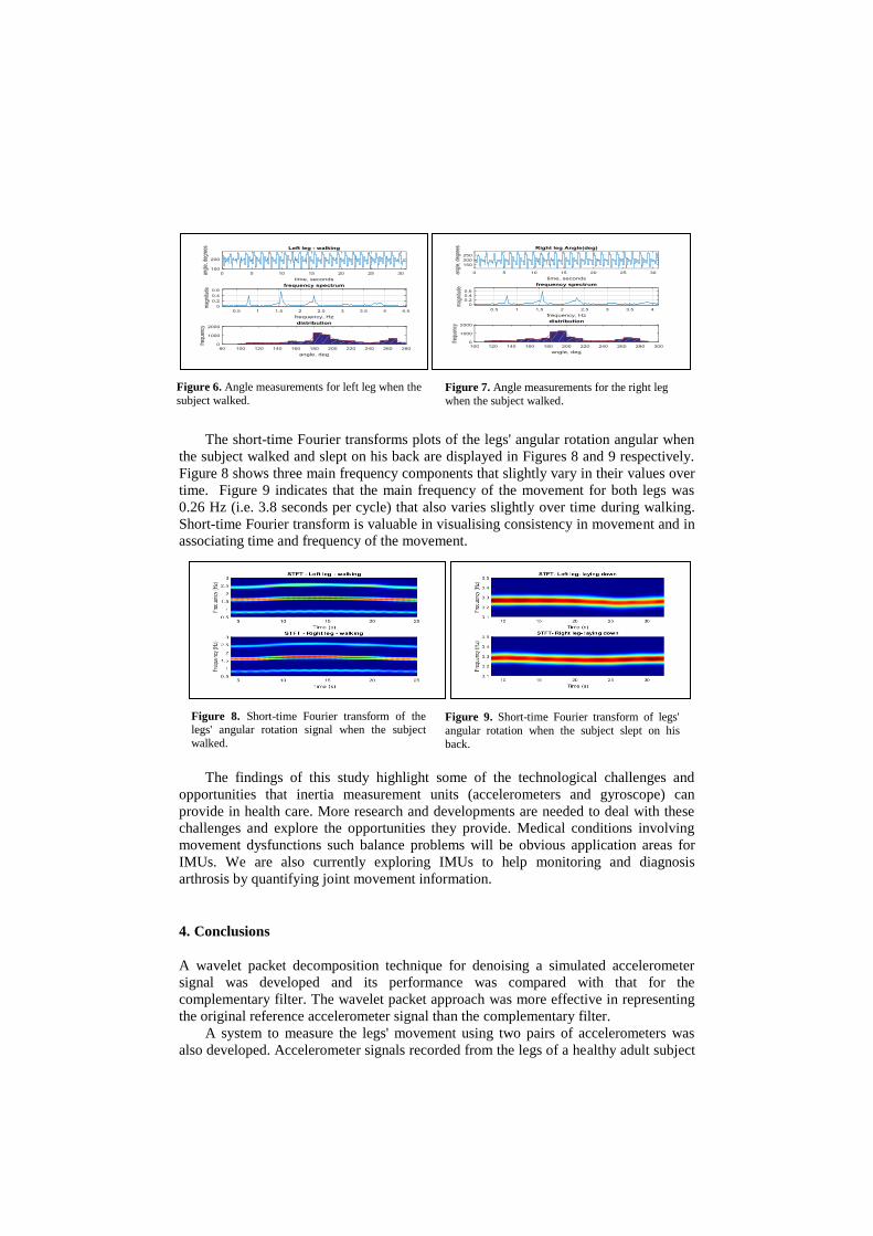
The short-time Fourier transforms plots of the legs' angular rotation angular when
the subject walked and slept on his back are displayed in Figures 8 and 9 respectively.
Figure 8 shows three main frequency components that slightly vary in their values over
time. Figure 9 indicates that the main frequency of the movement for both legs was
0.26 Hz (i.e. 3.8 seconds per cycle) that also varies slightly over time during walking.
Short-time Fourier transform is valuable in visualising consistency in movement and in
associating time and frequency of the movement.
The findings of this study highlight some of the technological challenges and
opportunities that inertia measurement units (accelerometers and gyroscope) can
provide in health care. More research and developments are needed to deal with these
challenges and explore the opportunities they provide. Medical conditions involving
movement dysfunctions such balance problems will be obvious application areas for
IMUs. We are also currently exploring IMUs to help monitoring and diagnosis
arthrosis by quantifying joint movement information.
4. Conclusions
A wavelet packet decomposition technique for denoising a simulated accelerometer
signal was developed and its performance was compared with that for the
complementary filter. The wavelet packet approach was more effective in representing
the original reference accelerometer signal than the complementary filter.
A system to measure the legs' movement using two pairs of accelerometers was
also developed. Accelerometer signals recorded from the legs of a healthy adult subject
Figure 6. Angle measurements for left leg when the
subject walked.
Figure 7. Angle measurements for the right leg
when the subject walked.
Figure 8. Short-time Fourier transform of the legs' angular rotation signal when the subject
walked.
Figure 9. Short-time Fourier transform of legs'
angular rotation when the subject slept on his
back.

who slept on his back and moved his legs in turn from fully stretched on the ground to
fully bent close to his chest and while he walked were analysed. The results obtained
indicated differences between angular rotation, angular velocity, angular velocity and
total angular displacement for the legs for the related scenarios. The approaches can be
valuable for investigating movement related disorders.
References
[1] H. Zeng and Y. Zhao, Sensing movement: microsensors for body motion measurement, Sensors, 11 (2011), 636-660.
[2] A. Godfrey, R. Conway, D. Meagher, and G. ÓLaighin, Direct measurement of human movement by
accelerometry, . Medical Engineering & Physics, 30(10) (2008), 1364-1386. [3] A.I. Cuesta-Vargas, Galàn-Mercant and J.W. Williams, The use of inertial sensors system for human
motion analysis. Physical Therapy Reviews, 15(6) (2010), 462-473. doi:10.1179/1743288X11Y.0000000006.
[4] D. Rodriguez-Martin, C. Perez-Lopez, A. Sama, J. Cabestany, and A. Catala (2013), A wearable inertial
measurement unit for long-term monitoring in the dependency care area, Sensors, 13(10) (2013), 14104. doi:10.3390/s131014079.
[5] T. Seel, J. Raisch and T. Schauer, IMU-based joint angle measurement for gait analysis, Sensors (Basel,
Switzerland), 14(4) (2014). 6891-6909. doi:10.3390/s140406891. [6] J.Z. Sasiadek, Sensor fusion. Annual Reviews in Control, 26(2) (2014), 203-228.
[7] P.H. Veltink, H.B.J. Bussman, F. Koelma, H.M. Franken, W.L.J. Martens and R.C. Lummel, The
feasibility of posture and movement detection by accelerometry, in the 5th Annual International Conference of the IEEE Engineering in Medicine and Biology Society, (1993), October 28-31, San
Diego, CA, 1230-1231.
[8] G. Kamen, C. Patten, C.D. Du, and S. Sison, An accelerometry-based system for the assessment of balance and postural sway. Gerontology, 44(1) (1988) 40-45. doi:ger44040 [pii].
[9] R.E. Mayagoitia, J.C. Lötters, P.H. Veltink and H. Hermens, Standing balance evaluation using a triaxial
accelerometer. Gait & Posture, 16(1) (2002), 55-59. [10] H.J. Luinge and P.H. Veltink, Inclination measurement of human movement using a 3-D
accelerometer with autocalibration. IEEE Transactions on Neural Systems and Rehabilitation
Engineering, 12(1) (2004), 112-121. [11] J.J. Kavanagh and H.B. Menz, Accelerometry: A technique for quantifying movement patterns during
walking, Gait & Posture, 28(1) (2008), 1-15.
[12] S.K. Hong, Fuzzy logic based closed-loop strapdown attitude system for unmanned aerial vehicle (UAV). Sensors and Actuators A: Physical, 107(2) (2003), 109-118.
doi:http://dx.doi.org.lcproxy.shu.ac.uk/10.1016/S0924-4247(03)00353-4.
[13] X. Shen, M. Yao, W. Jia and D. Yuan, Adaptive complementary filter using fuzzy logic and
simultaneous perturbation stochastic approximation algorithm. Measurement, 45(5) (2012), 1257-
1265. doi:10.1016/j.measurement.2012.01.011.
[14] J. Calusdian, X. Yun, and E. Bachmann, Adaptive-gain complementary filter of inertial and magnetic data for orientation estimation, Robotics and Automation (ICRA), (2011), IEEE International
Conference on, 1916-1922. doi:10.1109/ICRA.2011.5979957.
[15] S.P. Tseng, L. Wen-Lung, S. Chih-Yang, H Jia-Wei and C. Chin-Sheng, Motion and attitude estimation using inertial measurements with complementary filter. IEEE Explore, Proceedings off 2011 8th Asian
Control Conference (ASCC), Kaohsiung, Taiwan, May 15-18, (2011), 863-868.
[16] Y. Tian, H. Wei, and J. Tan, An adaptive-gain complementary filter for real-time human motion tracking with MARG sensors in free-living environments, IEEE Transactions on Neural Systems and
Rehabilitation Engineering, 21(2) (2013), 254-264. doi:10.1109/TNSRE.2012.2205706.
[17] Analog Devices, Small, low power, 3-Axis±3 g accelerometer. ADXL335, (2009), https://www.sparkfun.com/datasheets/Components/SMD/adxl335.pdf .
[18] H. Nwaizu, R. Saatchi, and D. Burke, Accelerometer based human joints' range of movement
measurement, IEEE Explor, (2016), 10th International Symposium on Communication Systems, Networks and Digital Signal Processing (CSNDSP).


![Reliability of 3D Lower Extremity Movement Analysis by ... · the lower limb joints’ (i.e., hip, knee, and ankle) kinematics measured by an inertial sensor system [7–9]. Cloete](https://static.fdocuments.us/doc/165x107/5f5094dec861c41e5762582c/reliability-of-3d-lower-extremity-movement-analysis-by-the-lower-limb-jointsa.jpg)